Shear Strength of Soils
|
|
|
- Austin Butler
- 5 years ago
- Views:
Transcription

1 Shear Strength of Soils
2 Shear failure Soils generally fail in shear strip footing embankment failure surface mobilised shear resistance At failure, shear stress along the failure surface reaches the shear strength. th


3 Shear failure failure surface The soil grains slide over each other along the failure surface. No crushing of individual grains. SIVA Copyright 2001
4 Shear failure At failure, shear stress along the failure surface () reaches the shear strength th ( f ). SIVA Copyright 2001
5 Mohr-Coulomb Failure Criterion f c tan cohesion c f friction angle SIVA Copyright 2001 f is the maximum shear stress the soil can take without failure, under normal stress of.
6 Mohr-Coulomb Failure Criterion Shear strength consists of two components: cohesive and frictional. f c f tan c f c f tan frictional component f SIVA Copyright 2001


7 cand are measures of shear strength. Higher the values, higher the shear strength.
8 Mohr Circles & Failure Envelope Y X Soil elements at X Y different locations X ~ failure Y ~stable
9 Mohr Circles & Failure Envelope The soil element does not fail if the Mohr circle is contained within the envelope c GL Y c c c + Initially, Mohr circle is a point
10 Mohr Circles & Failure Envelope As loading progresses, Mohr circle becomes larger c GL Y c c.. and finally failure occurs when Mohr circle touches the envelope
11 Orientation of Failure Plane Y Failure plane oriented at 45 + /2 to horizontal c GL 45 + / /2 Y c c c + 90+
12 Mohr circles in terms of & v v u h X = X h + X u effective stresses total stresses h v h u v
13 Envelopes in terms of & Identical specimens initially subjected to different isotropic stresses ( c ) and then loaded axially to failure c c f Initially c Failure c u f At failure, c, in terms of 3 = c ; 1 = c + f c, 3 = 3 u f ; 1 = 1 -u f in terms of
14 1-3 Relation at Failure 1 X 3 X soil element at failure 3 1 c 1 3 tan 2 (45 / 2) 2 tan(45 / 2) c 3 1 tan 2 (45 / 2) 2c tan(45 / 2)


15 2001 Brooks/ /Cole, a division of Thomson Le earning, Inc. Thomson Learning is a trademark used herein und der license. Figure 11.3 Mohr s circle and failure envelope SIVA Copyright 2001
16 Soil strength Soils are essentially frictional materials the strength depends on the applied stress Strength is controlled by effective stresses water pressures are required Soil strength depends on drainage different strengths will be measured for a given soil that (a) deforms at constant volume (undrained) and (b) deforms without developing excess pore pressures (drained)
17 Mohr-Coulomb failure criterion n The limiting shear stress (soil strength) is given by = c + n tan where c = cohesion (apparent) = friction angle
18 Mohr-Coulomb failure criterion The parameters c, are in general not soil constants. They depend on the initial state of the soil (OCR or I d ) the type of loading (drained or undrained) The Mohr-Coulomb criterion is an empirical criterion, and the failure locus is only locally linear. Extrapolation outside the range of normal stresses for which h it has been determined d is likely to be unreliable.
19 Effective stress failure criterion If the soil is at failure the effective stress failure criterion i will always be satisfied. c' tan ' n c and are known as the effective (or drained) strength parameters.
20 Effective stress failure criterion If the soil is at failure the effective stress failure criterion i will always be satisfied. c' tan ' n c and are known as the effective (or drained) strength parameters. Soil behaviour is controlled by effective stresses, and the Soil behaviour is controlled by effective stresses, and the effective strength parameters are the fundamental strength parameters. But they are not necessarily soil constants.
21 Total stress failure criterion If the soil is taken to failure at constant volume (undrained) then the failure criterion can be written in terms of total stress as c u n tan u c u and u are known as the undrained strength parameters
22 Total stress failure criterion If the soil is taken to failure at constant volume (undrained) then the failure criterion can be written in terms of total stress as c u n tan u c u and u are known as the undrained strength parameters These parameters are not soil constants, they depend strongly on the moisture content of the soil.
23 Total stress failure criterion If the soil is taken to failure at constant volume (undrained) then the failure criterion can be written in terms of total stress as c u n tan u c u and u are known as the undrained strength parameters These parameters are not soil constants, they depend strongly on the moisture content of the soil. The undrained strength is only relevant in practice to clayey soils that in the short term remain undrained. Note that as the pore pressures are unknown for undrained loading the effective stress failure criterion cannot be used.
24 1. Shear Box Test Tests to measure soil strength Motor drive Top platen Normal load Soil Load cell to measure Shear Force Porous plates Rollers Measure relative horizontal displacement, dx vertical displacement of top platen, dy
25
26 Shear box test Usually only relatively slow drained tests are performed in shear box apparatus. For clays rate of shearing must be chosen to prevent excess pore pressures building up. For sands and gravels tests can be performed quickly Tests on sands and gravels are usually performed dry. Water does not significantly affect the (drained) strength. If there are no excess pore pressures and as the pore pressure is approximately zero the total and effective stresses will be identical. The failure stresses thus define an effective stress failure envelope from which the effective (drained) strength parameters c, can be determined.
27 Typical drained shear box results Shear Load (F) Normal load increasing Horizontal displacement (dx)
28 Typical drained shear box results = F/A Peak Ultimate N 1 N 2 = N/A


29 Figure 11.6 Plot of shear stress and change in height of specimen against shear displacement for loose and dense dry sand (direct shear test) 2001 Bro ooks/cole, a division of Thomso on Learning, Inc. Thomson Learn ning is a trademark used herein n under license.
30 Interpretation of shear box tests A peak and an ultimate failure locus can be obtained from the results each with different c and values. All soils are essentially frictional and continued shearing results in them approaching a purely frictional state where c = 0. Normally consolidated clays (OCR=1) and loose sands do not show separate peak and ultimate failure loci, and for soils in these states c = 0. Overconsolidated clays and dense sands have peak strengths with c > 0. Note that dense sands do not possess any true cohesion (bonds), the apparent cohesion results from the tendency of soil to expand when sheared.
31 Shear box test - advantages Easy and quick test for sands and gravels Large deformations can be achieved by reversing shear direction. This is useful for determining the residual strength of a soil Large samples may be tested in large shear boxes. Small samples may give misleading results due to imperfections (fractures and fissures) or the lack of them. Samples may be sheared along predetermined planes. This is useful when the shear strengths along fissures or other selected planes are required.
32 Shear box test - disadvantages Non-uniform deformations and stresses in the specimen. The stress-strain behaviour cannot be determined. The estimated stresses may not be those acting on the shear plane. There is no means of estimating pore pressures so effective stresses cannot be determined from undrained tests Undrained strengths are unreliable because it is impossible to prevent localised drainage without high shearing rates In practice shear box tests are used to get quick and crude estimates of failure parameters
33 2. The Triaxial Test Tests to measure soil strength Deviator load Cell water O-ring seals Cell pressure Soil Confining cylinder Rubber membrane Porous filter disc Pore pressure and volume change
34
35 Triaxial Test Apparatus piston (to apply deviatoric stress) failure plane O-ring soil sample at failure perspex cell impervious membrane porous stone water cell pressure back pressure pedestal pore pressure or volume change
36 Types of Triaxial Tests deviatoric stress () Under all-around Shearing (loading) cell pressure c Is the drainage valve open? Is the drainage valve open? yes no yes no Consolidated U D i d Undrained sample Unconsolidated sample Drained loading loading
37 Types of Triaxial Tests Depending on whether drainage is allowed or not during initial isotropic cell pressure application, and shearing, there are three special types of triaxial tests that have practical significances. They are: Consolidated Drained (CD) test Consolidated Undrained (CU) test Unconsolidated Undrained (UU) test


38 For unconsolidated undrained test, in terms of total stresses, u = 0 Granular soils have no cohesion. c = 0 & c = 0 For normally consolidated clays, c = 0 & c = 0.
39 CD, CU and UU Triaxial Tests Consolidated Drained (CD) Test no excess pore pressure throughout the test very slow shearing to avoid build-up of pore pressure gives c and Can be days! not desirable Use c and for analysing fully drained Use c and for analysing fully drained situations (e.g., long term stability, very slow loading)
40 CD, CU and UU Triaxial Tests Consolidated Undrained (CU) Test pore pressure develops during shear Measure gives c and faster than CD (preferred way to find c and )
41 CD, CU and UU Triaxial Tests Unconsolidated Undrained (UU) Test pore pressure develops during shear very quick test Not measured unknown analyse in terms of gives c u and u Use c u and u for analysing undrained situations (e.g., short term stability, quick loading) = 0; i.e., failure envelope is horizontal
42 1-3 Relation at Failure 1 X 3 X soil element at failure 3 1 c 1 3 tan 2 (45 / 2) 2 tan(45 / 2) c 3 1 tan 2 (45 / 2) 2c tan(45 / 2)
43 Stress Point v h X stress point q stress point ( v - h )/2 h ( v + h )/2 v h p 2 v q v h 2 p or p
44 Stress Path During loading q Stress path is the locus of stress points Stress path Stress path is a convenient way to keep track of the progress in loading with respect to failure envelope. p or p
45 Failure Envelopes q failur e tan -1 (sin ) c ccos cos stress path p During loading (shearing).
46 Pore Pressure Parameters A simple way to estimate the pore pressure change in undrained loading, in terms of total stress changes ~ after Skempton (1954) 1 u B A Y 3 ( ) u =? Skempton s pore pressure parameters A and B
47 B = u / σ 3 If soil is saturated B=1, therefore Therefore, u = σ 3 + A ( σ 1 - σ 3 ) If σ 3 = 0, then A = u / (σ 1 - σ 3 )
48 Pore Pressure Parameters B-parameter B = f (saturation,..) For saturated soils, B 1. A-parameter at failure (A f ) A f = f(ocr) For normally consolidated clays A f 1. For heavily overconsolidated clays A f is negative.
49 Stresses in triaxial specimens r F = Deviator load r r = Radial stress (cell pressure) a = Axial stress
50 Stresses in triaxial specimens r F = Deviator load r r = Radial stress (cell pressure) a = Axial stress From equilibrium i we have a r F A
51 Stresses in triaxial specimens F/A is known as the deviator stress, and is given the symbol q q a r ( ) ( ) 1 3 The axial and radial stresses are principal stresses If q = 0 increasing cell pressure will result in volumetric compression if the soil is free to drain. The effective stresses will increase and so will the strength increasing pore water pressure if soil volume is constant (that is, undrained). As the effective stresses cannot change it follows that t u = r Increasing q is required to cause failure
52 Strains in triaxial specimens From the measurements of change in height, dh, and change in volume dv we can determine Axial strain dh a h 0 Volume strain V dv V V 0 where h 0 is the initial height and V 0 is the initial volume
53 Strains in triaxial specimens From the measurements of change in height, dh, and change in volume dv we can determine Axial strain dh a h 0 Volume strain V dv V V 0 where h 0 is the initial height and V 0 is the initial volume It is assumed that the specimens deform as right circular cylinders. The cross-sectional area, A, can then be determined from A = A o 1 + dv V0 1 + dh h 0 = A o 1 - v 1 - a
54 Advantages of the triaxial test Specimens are subjected to (approximately) uniform stresses and strains The complete stress-strain-strength behaviour can be investigated Drained and undrained tests can be performed Pore water pressures can be measured in undrained tests, allowing effective stresses to be determined Different combinations of cell pressure and axial stress can be Different combinations of cell pressure and axial stress can be applied
55 Typical triaxial results q Increasing cell pressure a
56 Interpretation of Laboratory results 1. Drained shear loading In laboratory tests the loading rate is chosen so that no excess water pressures will be generated, and the specimens are free to drain. Effective stresses can be determined from the applied total stresses and the known pore water pressure. Only the effective strength parameters c and have any relevance to drained tests. It is possible to construct a series of total stress Mohr circles but the inferred total stress (undrained) strength parameters are meaningless.
57 Interpretation of Laboratory results Effective strength parameters are generally used to check the long term stability (that is when all excess pore pressures have dissipated) of soil constructions. For sands and gravels pore pressures dissipate rapidly and the effective strength parameters can also be used to check the short term stability. In principle the effective strength parameters can be used to In principle the effective strength parameters can be used to check the stability at any time for any soil type. However, to do this the pore pressures in the ground must be known and in general they are only known in the long term.
58 2. Undrained loading Interpretation of Laboratory results In undrained laboratory tests no drainage from the sample must occur, nor should there be moisture redistribution within the sample. In the shear box this requires fast shear rates. In triaxial tests slower loading rates are possible because conditions are uniform and drainage from the sample is easily prevented. In a triaxial test with pore pressure measurement the effective In a triaxial test with pore pressure measurement the effective stresses can be determined and the effective strength parameters c, evaluated. These can be used as discussed previously to evaluate long term stability.
59 Interpretation of Laboratory results The undrained tests can also be used to determine the total (or undrained) strength parameters c u, u. If these parameters are to be relevant to the ground the moisture content must be the same. This can be achieved either by yperforming UU tests or by using CIU tests and consolidating to the in-situ stresses. The total (undrained) strength parameters are used to assess the short term stability of soil constructions. ctions It is important that no drainage should occur if this approach is to be valid. For example, a total stress analysis would not be appropriate for sands and gravels. For clayey soils a total stress analysis is the only simple way to assess stability N t th t d i d t th b d t i d f il b t th Note that undrained strengths can be determined for any soil, but they may not be relevant in practice
60 Relation between effective and total stress criteria Three identical saturated soil samples are sheared to failure in UU Three identical saturated soil samples are sheared to failure in UU triaxial tests. Each sample is subjected to a different cell pressure. No water can drain at any stage.
61 Relation between effective and total stress criteria Three identical saturated soil samples are sheared to failure in UU triaxial tests. Each sample is subjected to a different cell pressure. No water can drain at any stage. At failure the Mohr circles are found to be as shown 3 1
62 Relation between effective and total stress criteria Three identical saturated soil samples are sheared to failure in UU triaxial tests. Each sample is subjected to a different cell pressure. No water can drain at any stage. At failure the Mohr circles are found to be as shown 3 1 We find that all the total stress Mohr circles are the same size, and therefore u = 0 and = s u = c u = constant
63 Relation between effective and total stress criteria Because each sample is at failure, the fundamental effective stress failure condition must also be satisfied. As all the circles have the same size there must be only one effective stress Mohr circle c' n tan '
64 Relation between effective and total stress criteria Because each sample is at failure, the fundamental effective stress failure condition must also be satisfied. As all the circles have the same size there must be only one effective stress Mohr circle c' n tan ' We have the following relations c u = N + 2 c N 1 3
65 Relation between effective and total stress criteria The different total stress Mohr circles with a single effective stress Mohr circle indicate that the pore pressure is different for each sample. As discussed previously increasing the cell pressure without allowing drainage has the effect of increasing the pore pressure by the same amount (u = r ) with no change in effective stress. The change in pore pressure during shearing is a function of the initial effective stress and the moisture content. As these are identical for the three samples an identical strength is obtained.
66 Significance of undrained strength parameters It is often found that a series of undrained tests from a particular site give a value of u that is not zero (c u not constant). If this happens either the samples are not saturated, or the samples have different moisture contents If the samples are not saturated analyses based on undrained behaviour will not be correct The undrained strength c u is not a fundamental soil property. If the moisture content changes so will the undrained strength.
67 Example In an unconsolidated undrained triaxial test the undrained strength is measured as 17.5 kpa. Determine the cell pressure used in the test if the effective strength parameters are c = 0, = 26 o and the pore pressure at failure is 43 kpa.
68 Example In an unconsolidated undrained triaxial test the undrained strength is measured as 17.5 kpa. Determine the cell pressure used in the test if the effective strength parameters are c = 0, = 26 o and the pore pressure at failure is 43 kpa. Analytical solution = = Undrained strength
69 Example In an unconsolidated undrained triaxial test the undrained strength is measured as 17.5 kpa. Determine the cell pressure used in the test if the effective strength parameters are c = 0, = 26 o and the pore pressure at failure is 43 kpa. Analytical solution = = Undrained strength Failure criterion = N + 2 c N 1 3
70 Example In an unconsolidated undrained triaxial test the undrained strength is measured as 17.5 kpa. Determine the cell pressure used in the test if the effective strength parameters are c = 0, = 26 o and the pore pressure at failure is 43 kpa. Analytical solution = = Undrained strength Failure criterion = N + 2 c N 1 3 Hence = 57.4 kpa, = 22.4 kpa and cell pressure (total stress) = + u = 65.4 kpa
71 Graphical solution
72 Graphical solution
73 Graphical solution
74
75
76
77
78
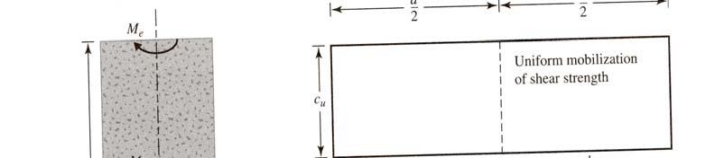
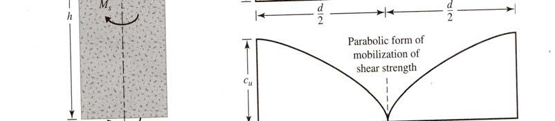
79 T = M s + M e + M e M s = (πdh)c u x d/2 T = πc u [( d 2 h/2) +(βd 3 /4)] β = ½ for triangular mobilization of undrained shear strength β = 2/3 for uniform mobilization of undrained d shear strength β = 3/5 for parabolic mobilization of undrained shear strength
EAT 212 SOIL MECHANICS
 EAT 212 SOIL MECHANICS Chapter 4: SHEAR STRENGTH OF SOIL PREPARED BY SHAMILAH ANUDAI@ANUAR CONTENT Shear failure in soil Drained and Undrained condition Mohr-coulomb failure Shear strength of saturated
This document downloaded from vulcanhammer.net vulcanhammer.info Chet Aero Marine
 This document downloaded from vulcanhammer.net vulcanhammer.info Chet Aero Marine Don t forget to visit our companion site http://www.vulcanhammer.org Use subject to the terms and conditions of the respective
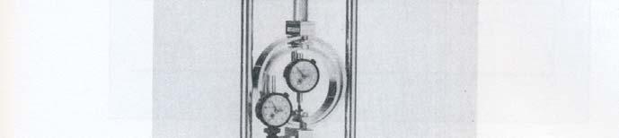
Laboratory Tests to Determine Shear Strength of Soils
 Triaxial Testing Laboratory Tests to Determine Shear Strength of Soils Geotechnical Engineering II (ENGI 6723) Presented by Rodney P. McAffee, Ph.D., P.Eng. Laboratory Tests to Determine Shear Lecture
Compressibility and One Dimensional Consolidation of Soil
 Compressibility and One Dimensional Consolidation of Soil ONE DIMENSIONAL SETTLEMENT BEHAVIOUR Initial condition U= u0 u0 is hydrostatic pore water pressure Effective stress, σo' Undrained loading U =
EFFECT OF COMPACTION ON THE UNSATURATED SHEAR STRENGTH OF A COMPACTED TILL
 EFFECT OF COMPACTION ON THE UNSATURATED SHEAR STRENGTH OF A COMPACTED TILL Vanapalli, S.K., Pufahl, D.E., and Fredlund, D.G. (University of Saskatchewan, Saskatoon, SK., Canada, S7N 5A9) Abstract An experimental
CHAPTER 8 SLOPE STABILITY ANALYSIS
 TM 5-818-1 / AFM 88-3. Chap. 7 CHAPTER 8 SLOPE STABILITY ANALYSIS 8-1. General. This chapter is concerned with characteristics and critical aspects of the stability of excavation slopes; methods of designing
Unsaturated Shear Strength Behavior under Unconsolidated Undrained Tests
 Unsaturated Shear Strength Behavior under Unconsolidated Undrained Tests Majid Sokhanvar 1, Ir. Dr. Azman Kassim 2 1: Master of Engineering (Civil- Geotechnics), Faculty of Civil Engineering, Universiti
Global Journal of Engineering Science and Research Management
 ANALYSIS OF SOIL EFFECTIVE SHEAR STRENGTH PARAMETERS CONSIDERING DIFFERENT SPECIMEN DIAMETERS IN TRIAXIAL TESTS Fernando Feitosa Monteiro*, Yago Machado Pereira de Matos, Mariana Campos Fontenelle, Beatriz
COMPARISON OF SHEAR STRENGTH PARAMETERS OF BLACK COTTON SOIL WITH EFFECT OF RELATIVE COMPACTION
 Vol-2 Issue-4 16 COMPARISON OF SHEAR STRENGTH PARAMETERS OF BLACK COTTON SOIL WITH EFFECT OF RELATIVE COMPACTION Prof. Usha k. Patel Assistant Professor, LDCE Prof. M. G. Vanza Associate Professor, LDCE
ISO/TS TECHNICAL SPECIFICATION
 TECHNICAL SPECIFICATION ISO/TS 17892-8 First edition 2004-10-15 Geotechnical investigation and testing Laboratory testing of soil Part 8: Unconsolidated undrained triaxial test Reconnaissance et essais
ScienceDirect. The Undrained Shear Strength of Overconsolidated Clays
 Available online at www.sciencedirect.com ScienceDirect Procedia Engineering 91 (2014 ) 317 321 XXIII R-S-P seminar, Theoretical Foundation of Civil Engineering (23RSP) (TFoCE 2014) The Undrained Shear
Problems with Testing Peat for Stability Analysis
 Problems with Testing Peat for Stability Analysis Dick Gosling & Peter Keeton Scottish Executive Document Published December 2006 Includes requirement for slope stability analysis using infinite slope
Consolidation Stress Effect On Strength Of Lime Stabilized Soil
 RESEARCH ARTICLE OPEN ACCESS Consolidation Stress Effect On Strength Of Stabilized Soil K. Saranya*, Dr. M. Muttharam** *(Department of Civil Engineering, Research Scholar, Anna University, Chennai-25)
An Experimental Study on Variation of Shear Strength for Layered Soils
 An Experimental Study on Variation of Shear Strength for Layered Soils Mr. Hemantkumar Ronad 1 DCE, M.Tech in Geotechnical Engg. Department of Civil Engineering 1, Basaveshwar Engineering College, Bagalkot-587102.
Undrained shear strength in the assessment of slope stability of water defenses
 Undrained shear strength in the assessment of slope stability of water defenses Geotechnical Lectures Evening - TU Delft Context New safety standards and assessment rules for water defenses (WBI 2017)
Slope stability assessment
 Engineering manual No. 25 Updated: 03/2018 Slope stability assessment Program: FEM File: Demo_manual_25.gmk The objective of this manual is to analyse the slope stability degree (factor of safety) using
Bearing Capacity Theory. Bearing Capacity
 Bearing Capacity Theory Bearing Capacity 1 Bearing Capacity Failure a) General Shear Failure Most common type of shear failure; occurs in strong soils and rocks b) Local Shear Failure Intermediate between
Prof. B V S Viswanadham, Department of Civil Engineering, IIT Bombay
 22 Module 5: Lecture -4 on Stability of Slopes Sudden drawdown Determination of most critical slip surface Criteria for most critical slip surface = Minimum factor of safety Trial and error approach involves
Mechanical Behavior of Soil Geotextile Composites: Effect of Soil Type
 Mechanical Behavior of Geotextile Composites: Effect of Type A.I. Droudakis and I.N. Markou Department of Civil Engineering, Democritus University of Thrace, Greece 12 Vas. Sofias str., GR-671 Xanthi,
Finite Element Methods against Limit Equilibrium Approaches for Slope Stability Analysis
 Finite Element Methods against Limit Equilibrium Approaches for Slope Stability Analysis H. Khabbaz 1, B. Fatahi 1, C. Nucifora 1 1 Centre for Built Infrastructure Research, School of Civil and Environmental
LABORATORY STUDY ON THE CONSOLIDATION SETTLEMENT OF CLAY-FILLED GEOTEXTILE TUBE AND BAGS
 Journal of GeoEngineering, Vol. 6, No. 1, pp. Chew 41-45, et al.: April Laboratory 2011 Study on the Consolidation Settlement of Clay-Filled Geotextile Tube and Bags 41 LABORATORY STUDY ON THE CONSOLIDATION
Shear strength features of unsaturated clayey sand by lab test
 Innov. Infrastruct. Solut. (2) 1:24 DOI 1.17/s42--3-y ORIGINAL PAPER Shear strength features of unsaturated clayey sand by lab test Qingyan Tian 1 Nigui Qian 2 Jiantong Zhang 3 Received: 29 May 2 / Accepted:
Numerical Analysis of the Bearing Capacity of Strip Footing Adjacent to Slope
 International Journal of Science and Engineering Investigations vol. 4, issue 46, November 25 ISSN: 225-8843 Numerical Analysis of the Bearing Capacity of Strip Footing Adjacent to Slope Mohammadreza Hamzehpour
PILE FOUNDATIONS CONTENTS: 1.0 Introduction. 1.1 Choice of pile type Driven (displacement) piles Bored (replacement) piles. 2.
 piles Bored (replacement) piles. 2.") PILE FOUNDATIONS CONTENTS: 1.0 Introduction 1.1 Choice of pile type 1.1.1 Driven (displacement) piles 1.1.2 Bored (replacement) piles 2.0 Analysis 2.0.1 Driving formulae 2.0.2 Soil mechanics 2.1 Piles
PILE FOUNDATIONS CONTENTS: 1.0 Introduction 1.1 Choice of pile type 1.1.1 Driven (displacement) piles 1.1.2 Bored (replacement) piles 2.0 Analysis 2.0.1 Driving formulae 2.0.2 Soil mechanics 2.1 Piles
Fine Coal Refuse 25 Years of Field and Laboratory Testing Data and Correlations
 Fine Coal Refuse 25 Years of Field and Laboratory Testing Data and Correlations October 1, 2018 Blaise E. Genes Gonzalo Castro, Ph.D., P.E. Thomas O. Keller, P. E. Fatma Ciloglu, Ph.D., P. E. Presentation
The University of Iowa Department of Civil & Environmental Engineering SOIL MECHANICS 53:030 Final Examination 2 Hours, 200 points
 The University of Iowa epartment of Civil & Environmental Engineering SOIL MECHNICS 53:030 Final Examination 2 Hours, 200 points Fall 1998 Instructor: C.C. Swan Problem #1: (25 points) a. In a sentence
Compaction. Compaction purposes and processes. Compaction as a construction process
 Compaction Compaction purposes and processes Specification and quality control Moisture condition value Compaction is a process that brings about an increase in soil density or unit weight, accompanied
Effect of pile sleeve opening and length below seabed on the bearing capacity of offshore jacket mudmats
 NGM 2016 Reykjavik Proceedings of the 17 th Nordic Geotechnical Meeting Challenges in Nordic Geotechnic 25 th 28 th of May Effect of pile sleeve opening and length below seabed on the bearing capacity
PULLOUT CAPACITY OF HORIZONTAL AND INCLINED PLATE ANCHORS IN CLAYEY SOILS
 PULLOUT CAPACITY OF HORIZONTAL AND INCLINED PLATE ANCHORS IN CLAYEY SOILS BALESHWAR SINGH Associate Professor Department of Civil Engineering Indian Institute of Technology Guwahati Guwahati 78139, India
Soil-Structure Interaction of a Piled Raft Foundation in Clay a 3D Numerical Study
 388 J. Eng. Technol. Sci., Vol. 48, No. 4, 2016, 388-407 Soil-Structure Interaction of a Piled Raft Foundation in Clay a 3D Numerical Study Endra Susila 1,* & Nita Anggraini 2 1 Geotechnical Engineering
GEOSYNTHETICS ENGINEERING: IN THEORY AND PRACTICE
 GEOSYNTHETICS ENGINEERING: IN THEORY AND PRACTICE Prof. J. N. Mandal Department of Civil Engineering, IIT Bombay, Powai, Mumbai 400076, India. Tel.022-25767328 email: cejnm@civil.iitb.ac.in Module - 8
ISO/TS TECHNICAL SPECIFICATION. Geotechnical investigation and testing Laboratory testing of soil Part 10: Direct shear tests
 TECHNICAL SPECIFICATION ISO/TS 17892-10 First edition 2004-10-15 Geotechnical investigation and testing Laboratory testing of soil Part 10: Direct shear tests Reconnaissance et essais géotechniques Essais
Backfill Stress and Strain Information within a Centrifuge Geosynthetic-Reinforced Slope Model under Working Stress and Large Soil Strain Conditions
 GeoCongress 2012 ASCE 2012 461 Yang, K-H., Zornberg, J.G., Liu, C-N. and Lin, H-D. (2012). Backfill Stress and Strain Information within a Centrifuge Geosynthetic-Reinforced Slope under Working Stress
APPENDIX D. Slope Stability Analysis Results for Soil and Overburden Storage Mounds
 Geotechnical Assessment Report APPENDIX D Slope Stability Analysis Results for Soil and Overburden Storage Mounds DABGeot/09059GA/Final Geotechnical Assessment Report STABILITY OF SOIL AND OVERBURDEN STORAGE
Strength of Materials for Embankment Dams
 United States Society on Dams Strength of Materials for Embankment Dams February 2007 A White Paper prepared by the USSD Committee on Materials for Embankment Dams U.S. Society on Dams Vision To be the
Undrained shear strength determination and correlations on Søvind Marl Grønbech, Gitte Lyng; Nielsen, Benjaminn Nordahl
 Aalborg Universitet Undrained shear strength determination and correlations on Søvind Marl Grønbech, Gitte Lyng; Nielsen, Benjaminn Nordahl Published in: NGM 2016 Proceedings Publication date: 2016 Document
Analysis of Pullout Resistance of Soil-Nailing in Lateritic Soil
 Analysis of Pullout Resistance of Soil-Nailing in Lateritic Soil B,L.A. Isaka 1, B.C. Madushanka 1 and N.H. Priyankara 1 1 Department of Civil and Environmental Engineering Faculty of Engineering University
DRAFT ONONDAGA LAKE CAPPING AND DREDGE AREA AND DEPTH INITIAL DESIGN SUBMITTAL H.3 STATIC SLOPE STABILITY ANALYSES
 DRAFT ONONDAGA LAKE CAPPING AND DREDGE AREA AND DEPTH INITIAL DESIGN SUBMITTAL H.3 STATIC SLOPE STABILITY ANALYSES Parsons P:\Honeywell -SYR\444576 2008 Capping\09 Reports\9.3 December 2009_Capping and
Darcy's law 16 Deformation 23-32, 53, 98-99, ; elastic 19-20, 148-
 INDEX Aeration estimation 210-213; modeling 216-217 Aggregate breakup 20, 53-56 Aggregate bulk density 13 Aggregate size distribution 109 Aggregate stability 60-70, 83-86, 89, 90, 93, 224, 231, 240; rate
THE ULTIMATE SKIN RESISTANCE OF CONCRETE PILE IN PARTIALLY SATURATED COHESIVE SOIL BY MODIFIED Β METHOD
 International Journal of Civil Engineering and Technology (IJCIET) Volume 9, Issue 10, October 2018, pp. 1882 1891, Article ID: IJCIET_09_10_187 Available online at http://www.iaeme.com/ijciet/issues.asp?jtype=ijciet&vtype=9&itype=10
EFFECT OF RELICT JOINTS IN RAIN INDUCED SLOPE FAILURES IN RESIDUAL SOIL
 EFFECT OF RELICT JOINTS IN RAIN INDUCED SLOPE FAILURES IN RESIDUAL SOIL Neethimappiriya Tharmalingam, Student (Email: neethi_26@yahoo.com) N.W.H. Lakshamana, Student (Email: hansaka8888@yahoo.com) R.D.T.B.
Experimental investigation and theoretical modelling of soft soils from mining deposits
 International Symposium on Deformation Characteristics of Geomaterials, September 3,, Seoul, Korea Experimental investigation and theoretical modelling of soft soils from mining deposits Herle, Ivo Institute
SOIL SLOPE STABILITY ANALYSIS. Analyses of slopes can be divided into two categories: 6,Chapter 13 J. MICHAEL DUNCAN
 6,Chapter 13 J. MICHAEL DUNCAN SOIL SLOPE STABILITY ANALYSIS Analyses of slopes can be divided into two categories: those used to evaluate the stability of slopes and those used to estimate slope movement.
A DETAILED ANALYSIS OF SLOPE STABILITY USING FINITE ELEMENT METHOD (FEM)
") A DETAILED ANALYSIS OF SLOPE STABILITY USING FINITE ELEMENT METHOD (FEM) S. Halder 1*, M. O. Imam 2 & M. S. Basir 1 1 Department of Civil & Water Resources Engineering, Chittagong University of Engineering
A DETAILED ANALYSIS OF SLOPE STABILITY USING FINITE ELEMENT METHOD (FEM) S. Halder 1*, M. O. Imam 2 & M. S. Basir 1 1 Department of Civil & Water Resources Engineering, Chittagong University of Engineering
4 Slope Stabilization Using EPS Geofoam at Route 23A
 Slope Stabilization Using EPS Geofoam at Route 23A 4.1 Introduction Geofoam introduced in recent years has provided solutions to a number of engineering problems. One of these problems is the slope stability
Stress-Strain and Strength Behavior of Undrained Organic Soil in Kupondol, Kathmandu
 TUTA/IOE/PCU Journal of the Institute of Engineering, Vol. 8, No. 1, pp. 113 118 TUTA/IOE/PCU All rights reserved. Printed in Nepal Fax: 977-1-5525830 Stress-Strain and Strength Behavior of Undrained Organic
THREE DIMENSIONAL SLOPE STABILITY
 THREE DIMENSIONAL SLOPE STABILITY Timothy D. Stark, Ph.D, PE Associate Professor of Civil and Environmental Engineering University of Illinois at Urbana-Champaign 205 N. Mathews Ave. Urbana, IL 61801 (217)
Triaxial testing of overconsolidated, low plasticity clay till
 NGM 2016 Reykjavik Proceedings of the 17 th Nordic Geotechnical Meeting Challenges in Nordic Geotechnic 25 th 28 th of May Triaxial testing of overconsolidated, low plasticity clay till A. H. Augustesen
Triaxial testing of overconsolidated, low plasticity clay till
 NGM 2016 Reykjavik Proceedings of the 17 th Nordic Geotechnical Meeting Challenges in Nordic Geotechnic 25 th 28 th of May Triaxial testing of overconsolidated, low plasticity clay till A. H. Augustesen
Identification of key parameters on Soil Water Characteristic Curve
 Identification of key parameters on Soil Water Characteristic Curve A.A. Heshmati 1, M.R. Motahari 2,* 1, 2 School of Civil Engineering, Iran University of Science and Technology P.O. Box 16765-163, Narmak,
Available online at ScienceDirect. Procedia Engineering 125 (2015 )
") Available online at www.sciencedirect.com ScienceDirect Procedia Engineering 125 (2015 ) 331 337 The 5th International Conference of Euro Asia Civil Engineering Forum (EACEF-5) Effect of Area Development
Available online at www.sciencedirect.com ScienceDirect Procedia Engineering 125 (2015 ) 331 337 The 5th International Conference of Euro Asia Civil Engineering Forum (EACEF-5) Effect of Area Development
Reinforcement with Geosynthetics
 Reinforcement with Geosynthetics GEO-SLOPE International Ltd. www.geo-slope.com 1200, 700-6th Ave SW, Calgary, AB, Canada T2P 0T8 Main: +1 403 269 2002 Fax: +1 888 463 2239 Introduction Reinforced earth
Triaxial Behaviour of Stabilized Soil by Quarry Dust
 Triaxial Behaviour of Stabilized Soil by Quarry Dust S. K. Vigneshwar 1, G.Vigneswaran 2, S.Gobinath 3, R. Thirumalai 4, Dr. S. Suresh Babu 5 UG Scholar, Dept. of Civil Engineering, Adhiyamaan College
Advanced Foundation Engineering. Introduction
 Shahrood University of Technology Department of Geotechnical Engineering Advanced Foundation Engineering Introduction Mohsen Keramati, Ph.D. Assistant Professor 1 - Detailed Course Plan Introduction (Geotechnical
GEOSYNTHETICS ENGINEERING: IN THEORY AND PRACTICE
 GEOSYNTHETICS ENGINEERING: IN THEORY AND PRACTICE Prof. J. N. Mandal Department of civil engineering, IIT Bombay, Powai, Mumbai 400076, India. Tel.022-25767328 email: cejnm@civil.iitb.ac.in Module - 7
[Gupta* et al., 5(7): July, 2016] ISSN: IC Value: 3.00 Impact Factor: 4.116
![[Gupta* et al., 5(7): July, 2016] ISSN: IC Value: 3.00 Impact Factor: 4.116](/thumbs/90/102184431.jpg "[Gupta* et al., 5(7): July, 2016] ISSN: IC Value: 3.00 Impact Factor: 4.116") [Gupta* et al., 5(7): July, 6] ISSN: 77-9655 IC Value: 3. Impact Factor: 4.6 IJESRT INTERNATIONAL JOURNAL OF ENGINEERING SCIENCES & RESEARCH TECHNOLOGY EFFECT OF DENSITY AND MOISTURE ON THE SLOPE STABILITY
[Gupta* et al., 5(7): July, 6] ISSN: 77-9655 IC Value: 3. Impact Factor: 4.6 IJESRT INTERNATIONAL JOURNAL OF ENGINEERING SCIENCES & RESEARCH TECHNOLOGY EFFECT OF DENSITY AND MOISTURE ON THE SLOPE STABILITY
Full Scale Model Test of Soil Reinforcement on Soft Soil Deposition with Inclined Timber Pile
 Full Scale Model Test of Soil Reinforcement on Soft Soil Deposition with Inclined Timber Pile Suheriyatna 1, L. Samang 2, M. W. Tjaronge 3 and T. Harianto 4 1 Doctoral Student, Department of Civil Engineering,
The Effect of Soil Suction on Slope Stability at Notch Hill
 The Effect of Soil Suction on Slope Stability at Notch Hill J. KRAHN EBA Engineering Consultants, Calgary, Alberta, Canada D.G. FREDLUND University of Saskatchewan, Saskatoon, Saskatchewan, Canada M.J.
LARGE-SCALE SHEAR TESTS ON INTERFACE SHEAR PERFORMANCE OF LANDFILL LINER SYSTEMS
 Proceeding of the 4 th Asian Regional Conference on Geosynthetics June 17-2, 28 Shanghai, China LARGE-SCALE SHEAR TESTS ON INTERFACE SHEAR PERFORMANCE OF LANDFILL LINER SYSTEMS M. Kamon 1, S. Mariappan
Stability of Inclined Strip Anchors in Purely Cohesive Soil
 Stability of Inclined Strip Anchors in Purely Cohesive Soil R. S. Merifield 1 ; A. V. Lyamin 2 ; and S. W. Sloan 3 Abstract: Soil anchors are commonly used as foundation systems for structures requiring
Rapid Drawdown with Multi-Stage
 1 Introduction Rapid Drawdown with Multi-Stage Stability analysis during rapid drawdown is an important consideration in the design of embankment dams. During rapid drawdown, the stabilizing effect of
Introduction. A soil is an earth concrete. Composition of a soil
 Introduction Soil is the result of the transformation of the underlying rock under the influence of a range of physical, chemical and biological processes related to biological and climatic conditions
EFFECTIVE STRESS RESPONSE OF CLAY TO UNDRAINED CYCLIC LOADING
 EFFECTIVE STRESS RESPONSE OF CLAY TO UNDRAINED CYCLIC LOADING by MUSTAPHA ZERGOUN B.A.Sc. Laval University, 1976 M.A.Sc, The University of British Columbia, 1983 A THESIS SUBMITTED IN PARTIAL FULFILMENT
Cavity expansion model to estimate undrained shear strength in soft clay from Dilatometer
 Cavity expansion model to estimate undrained shear strength in soft clay from Dilatometer Alan J. Lutenegger University of Massachusetts, Amherst, Massachusetts, USA Keywords: Dilatometer, clays, undrained
TECHNICAL REPORT STANDARD PAGE 2. Government Accession No. 3. Recipient's Catalog No.
 1. Report No. FHWA/LA.03/373 4. Title and Subtitle TECHNICAL REPORT STANDARD PAGE 2. Government Accession No. 3. Recipient's Catalog No. 5. Report Date Evaluation of the Effect of Synthetic Fibers and
Advanced Foundation Engineering. Soil Exploration
 Shahrood University of Technology Department of Geotechnical Engineering Advanced Foundation Engineering Soil Exploration Mohsen Keramati, Ph.D. Assistant Professor 1 - Introduction The field and laboratory
Keywords: slope stability, numerical analysis, rainfall, infiltration. Yu. Ando 1, Kentaro. Suda 2, Shinji. Konishi 3 and Hirokazu.
 Proceedings of Slope 25, September 27-3 th 25 SLOPE STABLITY ANALYSIS REGARDING RAINFALL-INDUCED LANDSLIDES BY COUPLING SATURATED-UNSATURATED SEEPAGE ANALYSIS AND RIGID PLASTIC FINITE ELEMENT METHOD Yu.
CHAPTER 1: INTRODUCTION. Road transport is an only means of transport that offers itself to the whole community
 1 CHAPTER 1: INTRODUCTION 1.1 General Road transport is an only means of transport that offers itself to the whole community alike. It is accepted fact that of all the modes the transportation, road transport
Dam Construction by Stages
 Dam Construction by Stages 1 Introduction This simple example demonstrates the simulation of staged embankment construction on soft ground. The primary objective of this example is to demonstrate the use
Evaluation of undrained shear strength of soft New Orleans clay using piezocone
 Evaluation of undrained shear strength of soft New Orleans clay using piezocone L. Wei & R. Pant HNTB Corporation, Baton Rouge, LA, USA M.T. Tumay Louisiana State University, Baton Rouge, LA, USA and Bogazici
GLOSSARY OF GROUND IMPROVEMENT VOCABULARY
 GLOSSARY OF GROUND IMPROVEMENT VOCABULARY Accelerator Agitator tank Atterberg limits Batch Blaine fineness Bleed Colonne ballastée Compaction grout Compaction crater Consolidation CPT CUU shear test A
1 Introduction. 2 General Pile Analysis Features. 2.1 Pile Internal Forces and Displacements
 RSPile version 1.0 RSPile is a general pile analysis software for analyzing driven pile installation, axially loaded piles and laterally loaded piles. It is capable of computing the axial capacity for
Undrained Shear Strength of Saturated Clay
 5 Figure 5. Typical failure criteria plot from direct shear box test results.
NUMERICAL STUDY ON STABILITY OF PLATE ANCHOR IN SLOPING GROUND
 Proceedings of the 4 th International Conference on Civil Engineering for Sustainable Development (ICCESD 2018), 9~11 February 2018, KUET, Khulna, Bangladesh (ISBN-978-984-34-3502-6) NUMERICAL STUDY ON
LOAD TRANSFER MECHANISM IN PULL-OUT TESTS
 Technical Paper by I.M. Alobaidi, D.J. Hoare and G.S. Ghataora LOAD TRANSFER MECHANISM IN PULL-OUT TESTS ABSTRACT: This paper presents a numerical method to predict soil-geotextile interface friction parameters.
Sea to Sky Geotechnique 2006
 INTERFACE SHEAR-STRENGTH PROPERTIES OF TEXTURED POLYETHYLENE GEOMEMBRANES Eric Blond, CTT Group / SAGEOS, Quebec, Canada Guy Elie, Solmax International, Quebec, Canada ABSTRACT In order to better characterize
GEOTEXTILE REINFORCED TWO LAYER SOIL SYSTEM WITH KUTTANAD CLAY OVERLAIN BY LATERITE SOIL
 GEOTEXTILE REINFORCED TWO LAYER SOIL SYSTEM WITH KUTTANAD CLAY OVERLAIN BY LATERITE SOIL Selma James 1, Rakendu R 2 1P.G. Student, Department of Civil Engineering, Saintgits College of Engineering, Kerala,
Attachment D. Ring Shear Testing Report (Dr. Timothy Stark)
") Attachment D Ring Shear Testing Report (Dr. Timothy Stark) PORT OF ANCHORAGE INTERMODAL EXPANSION: Bootlegger Cove Clay Analysis and Testing Anchorage, Alaska (Figure by CH2M-HILL) Prepared for: CH2M
Attachment D Ring Shear Testing Report (Dr. Timothy Stark) PORT OF ANCHORAGE INTERMODAL EXPANSION: Bootlegger Cove Clay Analysis and Testing Anchorage, Alaska (Figure by CH2M-HILL) Prepared for: CH2M
Soil Strength and Slope Stability
 Soil Strength and Slope Stability J. Michael Duncan Stephen G. Wright @ WILEY JOHN WILEY & SONS, INC. CONTENTS Preface ix CHAPTER 1 INTRODUCTION 1 C HAPTER 2 EXAMPLES AND CAUSES OF SLOPE FAILURE 5 Examples
Lightweight aggregates in Civil Engineering applications. Arnstein Watn Senior Scientist, SINTEF
 Lightweight aggregates in Civil Engineering applications Arnstein Watn Senior Scientist, SINTEF SINTEF Independent Multiscience Research Institute About 1800 employees Closely linked to the Universities
BITUMINOUS DIGITRAC AUTO STABILITY PRESS MARSHALL AUTOMATIC DIGITAL TESTER MARSHALL TESTING MACHINE W/ RECORDER MODELS
 18 BITUMINOUS DIGITRAC AUTO STABILITY PRESS The DigiTrac stability press for the Marshall method allows the operator to initially set up the platen and then the load and flow values are digitally tracked
Prof. B V S Viswanadham, Department of Civil Engineering, IIT Bombay
 08 Soil Compaction -1 Activity (After Bell, 1993) Swell-Shrinkage response of clay = f (Period, magnitude of precipitation and evapotranspiration) Kaolinite Smallest swelling capacity Illite May swell
Experimental tests for geosynthetics anchorage trenches
 Experimental tests for geosynthetics anchorage trenches Girard H. Cemagref, Bordeaux, France Briançon L Cnam, Paris, France Rey E. Cnam, Paris, France Keywords: geosynthetics, anchorage trench, full-scale
SOIL STABILIZATION USING NATURAL FIBER COIR
 SOIL STABILIZATION USING NATURAL FIBER COIR Pooja Upadhyay 1, Yatendra Singh 2 1M.Tech student, Department of Civil Engineering, IEC Group of Institutions, U.P, India 2Assistant Professor, Department of
2.2 Soils 3 DIRECT SHEAR TEST
 507 c) GT TS 50: Nonwoven needle-punched, continuous filament, polypropylene geotextile, with mass per unit area of 200 g/m 2 and thickness of 1.9mm. d) Smooth HDPE geomembrane (GM) with average thickness
Strength Parameter Selection in Stability Analysis of Residual Soil Nailed Walls
 Strength Parameter Selection in Stability Analysis of Soil Nailed Walls Author Asoudeh, Atefeh, Oh, Erwin Published 2014 Journal Title International Journal of GEOMATE Copyright Statement 2014 GEOMATE
A comparison of numerical algorithms in the analysis of pile reinforced slopes
 175 A comparison of numerical algorithms in the analysis of pile reinforced slopes D. V. Griffiths 1, F. ASCE, Hang Lin 2 and Ping Cao 3 1 Division of Engineering, Colorado School of Mines, Golden, Colorado,
Load-Carrying Capacity of Stone Column Encased with Geotextile. Anil Kumar Sahu 1 and Ishan Shankar 2
 Load-Carrying Capacity of Stone Column Encased with Geotextile Anil Kumar Sahu 1 and Ishan Shankar 2 1 Professor, Department of Civil Engineering, Delhi Technological University, Delhi, India (sahuanilkr@yahoo.co.in)
Texas Transportation Institute The Texas A&M University System College Station, Texas
 . Report No. FHWA/TX-3/-P. Government Accession No. 3. Recipient's Catalog No. 4. Title and Subtitle ESTIMATING STRENGTH VERSUS LOCATION AND TIME IN HIGH-PLASTICITY CLAYS 5. Report Date February 3 Technical
Piles subject to excavation-induced soil movement in clay
 Piles subject to -induced soil movement in clay Des foundations soumis au mouvement du sol du a l' dans l'argile D.E.L. Ong, C.F. Leung & Y.K. Chow Centre for Soft Ground Engineering, National University
Behaviour of Black Cotton Soil Reinforced with Sisal Fibre
 10th National Conference on Technological Trends (NCTT09) 6-7 Nov 2009 Behaviour of Black Cotton Soil Reinforced with Sisal Fibre Santhi Krishna K. M Tech Student Department of Civil Engineering College
Study on Effect of Water on Stability or Instability of the Earth Slopes
 International Research Journal of Applied and Basic Sciences 2014 Available online at www.irjabs.com ISSN 2251-838X / Vol, 8 (9): 1482-1487 Science Explorer Publications Study on Effect of Water on Stability
GEOTEXTILE DEFORMATION ANALYSIS OF GEOSYNTHETIC CLAY LINERS WITH FEM
 Geotextile deformation analysis of Geosynthetic Clay Liners under high hydraulic heads with Finite Element Method VII International Conference on Textile Composites and Inflatable Structures STRUCTURAL
Design of Unpaved Roads A Geotechnical Perspective
 - CGTR 217 - NERIST Design of Unpaved Roads A Geotechnical Perspective Arindam Dey Assistant Professor Department of Civil Engineering Geotechnical Engineering Division IIT Guwahati 2 Introduction Road
Base resistance of individual piles in pile group
 th WSEAS Int. Conf. on ENVIRONMENT, ECOSYSTEMS and DEVELOPMENT, Tenerife, Spain, December 14-16, 27 111 Base resistance of individual piles in pile group MOHAMED M. SHAHIN Department of Civil Engineering
EFFECT OF CENTRAL PILE IN INCREASING THE BEARING CAPACITY OF BORED PILE GROUPS
 EFFECT OF CENTRAL PILE IN INCREASING THE BEARING CAPACITY OF BORED PILE GROUPS Mohamed M. Shahin Department of Civil Engineering, 7 th October University, Misurata,, Libya, E-mail: Mohamed_zubi@yahoo.com
APPLICATIONS IN FILTRATION AND DRAINAGE & EROSION CONTROL
 Lecture 36 APPLICATIONS IN FILTRATION AND DRAINAGE & EROSION CONTROL Prof. G L Sivakumar Babu Department of Civil Engineering Indian Institute of Science Bangalore 560012 Geotextile filter requirements:
FINAL COVER VENEER STABILITY ANALYSES FOR SCA DESIGN
 DRAFT ONONDAGA LAKE SEDIMENT CONSOLIDATION AREA CIVIL & GEOTECHNICAL FINAL DESIGN 12B12BAPPENDIX L FINAL COVER VENEER STABILITY ANALYSES FOR SCA DESIGN p:\honeywell -syr\444853 - lake detail design\09
Stability analysis of slopes with surcharge by LEM and FEM
 International Journal of Advanced Structures and Geotechnical Engineering ISSN 2319-5347, Vol. 04, No. 04, October 2015 Stability analysis of slopes with surcharge by LEM and FEM MD. MONIRUZZAMAN MONI,
This document downloaded from vulcanhammer.net vulcanhammer.info Chet Aero Marine
 This document downloaded from vulcanhammer.net vulcanhammer.info Chet Aero Marine Don t forget to visit our companion site http://www.vulcanhammer.org Use subject to the terms and conditions of the respective