Practical Guidance on Specifying GCL Overlaps to Account for Shrinkage i
|
|
|
- Jennifer Hensley
- 5 years ago
- Views:
Transcription
1 Practical Guidance on Specifying GCL Overlaps to Account for Shrinkage i Richard Thiel 1, Ken Criley 2, and Jakub Bryk 3 1 Richard Thiel, President of Thiel Engineering, and Vice President of Engineering for Vector Engineering, 143E Spring Hill Dr, Grass Valley, CA 95945, phone , fax , richard@rthiel.com 2 Ken Criley, Laboratory Manager for Vector Engineering, 143E Spring Hill Dr, Grass Valley, CA 95945, phone , fax , criley@vectoreng.com 3 Jakub Bryk, Staff Engineer for Vector Engineering, 143E Spring Hill Dr, Grass Valley, CA 95945, phone , fax , bryk@vectoreng.com This article provides preliminary recommendations for developing project-specific specifications related to the amount of GCL overlap required to compensate for potential panel shrinkage. These recommendations are based on an ongoing laboratory investigation that has been developed to replicate observed field conditions where GCL shrinkage has occurred. Although these results are preliminary, it was felt that publishing these recommendations at this time is appropriate given the seriousness of the concern. Background Although shrinkage of unreinforced GCL panels in the field has been acknowledged and managed for many years, the awareness of panel shrinkage of reinforced GCL products is very recent. The first published acknowledgement of this issue for reinforced products was by Thiel and Richardson (2005) which mentioned five incidences of GCL panel shrinkage that had been discovered in the fast few years. All the cases involved reinforced GCLs that had initially been overlapped 6 inches, and then were covered with a geomembrane which was left exposed for extended periods of time on the order of two months to five years. For various reasons, the owners of these facilities had to cut open or remove parts of the geomembrane, at which time they discovered that the GCL panels had shrunk in the widthwise direction anywhere from 10 inches up to 3 or more feet. Gaps existed between the GCL panels where there had initially been overlaps. A photograph of one such example is shown in Photo 1. Thiel and Richardson (2005) surmised several possible reasons why the shrinkage could occur, without attributing the cause to any particular hypothesis. In April 2005 the Geosynthetics Institute (GSI) published a white paper (Koerner and Koerner, 2005), describing their research and conclusions regarding the GCL shrinkage issue. This paper was later published in the June 2005 issue of GFR. They narrowed the plausible mechanisms that would lead to gaps on the GCL to three: (1) Shrinkage perhaps accompanied by cyclic wetting and drying ; (2) longitudinal steep-slope tensioning; and (3) contraction on relatively flat surfaces. The white paper strongly emphasized the steep-slope tension-necking as the leading causative mechanism leading to GCL panel separation. For the one case in South America that experienced very large amounts of separation on a regular basis on relatively flat slopes, they conjectured that GCL panel contraction was caused by expansion and contraction of the overlying textured geomembrane, which may have gathered the GCL and caused it to bunch up.
2 Their recommendations for designers were as follows [notes in italics by current authors]: 1. Cover exposed GM/GCL installations with at least 12 in. of soil in a timely manner. 2. Do not use GCLs with needlepunched nonwoven geotextiles on both sides unless one of the geotextiles is scrim reinforced. 3. Increase the GCL overlap to compensate for the potential panel separation. With the exception of one California case, an increase of 4-12 inches [above the standard 6 inches] would have been adequate in the other cases. [Actually, two out of the five cases experienced shrinkage gaps up to 3 feet.] 4. Protect the exposed GM/GCL composite during its exposure time by using thermal blankets, geofoam, or other insulation techniques. [The use of white-surfaced geomembrane is a very practical technique to help accomplish this.] 5. Develop a NDT Method to Detect GCL Panel Separation. 6. Create full-scale field test sites to study the conditions under which GCL panel separation occurs. [The authors are aware of two such ongoing field studies. Useful data from those studies may be available within the next year.] Wet-Dry Cycling During the panel discussion at the GRI-Geofrontiers conference in February 2005, Greg Richardson stated his belief that the most likely cause of the GCL shrinkage phenomenon was due to cyclic hydration and drying of the GCL panels. For very-high moisture content (w initial = 70%) non-reinforced GCLs, shrinkage by drying is not a new or surprising phenomenon. The authors firm has experienced this while performing CQA on projects with these types of materials, where dramatic shrinkage would occur from the beginning of the day to the end, with complete loss of overlaps. This phenomenon was mention by Mackey (1997). Cautions also exist in the manufacturer s literature for these products, and thus shrinkage-by-drying for these types of products was previously recognized. For reinforced GCLs, however, one drying cycle has not been observed to create such a problem. Certainly it has been verified by the current investigators, as well as the Geosynthetic Institute, that one cycle of drying, in both field and laboratory studies, would not result in shrinkage levels that are comparable to the case histories. Our laboratory studies indicate a maximum shrinkage of approximately 2% with one drying cycle, whereas the field-observed shrinkage was up to 10 times this amount. By the same token, it is not so critical whether or not the GCL picked up additional moisture through humidity or some other cause before installation. Again, one cycle does not make a large impact on shrinkage. Cyclic wetting and drying, however, can have a profound impact on GCL shrinkage, as demonstrated by the laboratory testing described later in this paper, and could fully account for the observed field case histories. How could the GCL go through wetting and drying cycles in the field? This is very plausible. Remember that the situation we are
3 discussing is a GM/GCL installation that is left exposed with no soil cover. During the daytime, the exposed geomembrane will increase in temperature due to the sun. This increase in temperature has been measured up to nearly 70 C on black geomembranes (Wellington and Daniel, 1995; Cadwallader et al., 1993), and would be the driving force for drying the GCL and underlying subgrade during the day. During the evening, when temperatures cool down and there is no sun, the vaporized moisture that is trapped below the geomembrane will condense into droplets. If there is an appreciable slope, the moisture may run downhill and gather at the toe, forming a water pillow. If there is only a slight slope, then the water would be available to go back into the GCL. At the same time that this is occuring, the natural matric-suction of the bentonite in the GCL will always have a tendency to draw moisture from the subgrade. The rate at which a GCL will draw moisture from the subgrade will be site specific, and depend on the subgrade moisture conditions and matric-suction characteristics of the soils. Thus, we have a mechanism for hydration/drying cycles of exposed GM/GCL installations. The magnitude of wetting and drying would be expected to vary substantially at different sites, different exposures (e.g. south vs north facing slope), from day-to-day, week-toweek, and season-to-season. Tension-Necking As mentioned previously, the GSI white paper strongly emphasized tension-necking as the leading causative mechanism to explain the observed GCL panel separation. While this mechanism does not apply to the case on the relatively flat slope, the GSI authors postulate that this could be a large contributing factor to situations on slopes. The GSI laboratory testing certainly indicates that any tension induced in the products will exacerbate potential necking problems. They also found that the amount of necking will vary between different products. While the necking phenomenon caused by tension is certainly a real and measurable cause and effect, at least two of the five cases were not suspected to have tension in the GCL. On the other hand, tension-necking was surmised to be the leading causative mechanism for panel separation at the Badlands project in California which had very steep slopes, approaching 1.5[H]:1[V]. The authors have also observed some downdrag of an unrestrained GCL on a 2:1 slope that appeared to be caused by the diurnal expansion and contraction of the overlying textured geomembrane, which suggests that this could be a potential mechanism for creating tension had the GCL been anchored at the top. There were some direct field measurements and observations made by the CQA monitor in the Virginia case described by Thiel and Richardson (2005) that suggest tensionnecking was not a factor for that project. In that case, which was on a 3:1 slope, we can first of all take note that the whole reason that the GCL panel separation was discovered was because the geomembrane had to be replaced due to the lack of Velcro effect. The type of geomembrane that was supplied for that project had a low-profile calendared texturization that did not provide sufficient grip and interface strength. The result was that the geomembrane would slide over the GCL as soil was being placed up the slope, and this slippage was a construction problem. Indeed, the lead author s experience in the
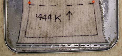
4 field with deployment of this type of textured geomembrane above a GCL is that there is so little of the Velcro -effect that a slip-sheet is not needed. Typically the lead author requires a slip sheet as a mandatory accessory during deployment of coextruded-textured geomembrane above geotextile-based products to avoid snagging of the fibers (as well as concomitant dulling of the texturing). Not so in the case of this type of textured geomembrane. Furthermore, the CQA monitor provided a photograph (Photo 2) of a location where an orange stripe had been painted across the intended tie-in of the new and old geomembranes and the underlying new GCL. The photograph clearly indicates that no movement of the unrestrained GCL had occurred in the 4-months that the disposition of the new geomembrane was being negotiated on that project. Movement of the new geomembrane was evident. In the words of the CQA monitor: HDPE definitely moved downhill (it had pulled out of the anchor trench), but the GCL did not seem to have moved at all. Thus, at least for the Virginia case, tension-necking does not seem like a plausible mechanism that would have caused GCL gaps to occur on a regular basis from panel-topanel. This case history, combined with the extensive shrinkage observed in the flatslope case, suggests that tension-necking may not be the leading mechanism that causes GCL panel separation. Nonetheless, the GSI white paper study is still valuable for showing the propensity for necking in the presence of tension, and how much more susceptible the double-nonwoven product with no scrim fabric was to necking compared to the other products. The same type of product was also found to be much more sensitive to shrinkage from wet-dry cycling than the other products. Current Laboratory Test Program Following up on the comments made by Greg Richardson, the lead author organized a laboratory testing program to evaluate the effects of cyclic hydration/drying on GCLs and geotextiles. The results were able to dependably reproduce the magnitude of shrinkage found in the field. The laboratory testing program, and some of the results, are described briefly here, with a more complete and detailed description being prepared for the upcoming international conference that will be held in Yokohama, Japan next year. The GCL and geotextile samples were cut to a dimension of 24 inches (MD) by 12 inches (XD). The samples were placed on aluminum baking pans with their as-received moisture content, and the two ends were clamped using a continuous bar-clamp screwed to the pan. The samples were in a relaxed, stress-free state when they were initially clamped. Photo No. 3 shows the initial sample setup. Two marks were precisely located near the mid-point edges of the samples, and the initial width between those marks were measured to the nearest 0.01 inch. The samples were then placed in an oven at 60 C and left to dry. This temperature was selected as representative of the temperature that black geomembrane will achieve when left exposed to the sun. After approximately 15 hours of drying, the samples were removed from the oven, allowed to cool to room temperature, and the width to the marks was measured and recorded. Approximately 500
5 ml of water was next evenly applied over the surface of the samples, and the samples were left to cure with the water at room temperature for approximately 8 hours. At the end of the 8 hours, the width to the marks was again measured and recorded, and then the samples were placed back in the oven to dry for another cycle. Each sequence of drying and wetting was considered one cycle, and so far up to 40 cycles have been performed for selected samples. Photo No. 4 shows how one of the samples looked after 20 cycles. Note the mid-point shrinkage-necking. Since the samples were clamped at their ends, shrinkage in the longitudinal direction would also have resulted in tension in the sample, which might further exacerbate the transverse necking. The root cause of the shrinkage, necking and tension in these experiments, though, was the wet-dry cycling. One area open for more investigation would be to perform tests on specimens with different length:width aspect ratios. The length:width ratio in these tests was approximately 2. In field installations ratios of 7-10 might be more common. The results for one GCL sample are plotted in Figure 1, which shows the percent change in width at the mid-point of the sample for each wet-dry portion of each cycle. The graph indicates that shrinkage occurs with each dry-side of the cycle, some recovery of the shrinkage upon re-wetting, but never complete recovery. For the sample shown, after 20 cycles there was approximately 10% of irrecoverable shrinkage on the wet-side of the cycle, and 20% shrinkage on the dry-side of the cycle. If the original panel width had been 15 feet, then these results would represent 1.5 to 3 feet of shrinkage, which is towards the upper end of what has actually been observed in the field. To date our laboratory testing program has been performed on 5 different fabric-encased GCL products, one geomembrane-backed GCL, one product was performed with two different amounts of water being added, and 5 different geotexiles. The range of response for the fabric-encased GCLs is about a factor of two, as shown in Figure 2. The geomembranebacked GCL did not shrink. We have observed a slower rate of shrinkage-per-cycle when less water is added, as illustrated in Figure 3. The geotextiles by themselves exhibited very little shrinkage. Testing of additional products and matrix variables is ongoing. Admittedly, the results depicted in Figures 1-3 represent worst-case conditions. It is unlikely that most installations would receive as much water as was added during the test, and then be dried to the extent performed in the test on a regular basis. A more likely scenario is that the magnitude of wetting and drying would be smaller on a day-to-day basis. On a seasonal basis, however, it is plausible that there may be extended periods of cool, overcast weather that would allow a fairly complete hydration of the GCL. Conversely, there may be extended periods of hot sunny weather that substantially dry the GCL. Thus, there may be small daily cycles superimposed on more significant seasonal cycles. This area definitely needs more research. A critical area that may experience the extremes simulated in the testing is at the toes of slopes, as described below. How Much Overlap is Needed?
6 Although the data from this study is preliminary, the authors believe it is appropriate to publish at this time to help designers and manufacturers get a handle on the answer to the question: How much overlap is needed? Although we cannot answer this question explicitly at this time, we can point to the following variables that would influence the answer: The amount of shrinkage/necking is likely related to the number of days that the liner system is left exposed without soil cover. We are assuming that shrinkage only occurs when a GM/GCL installation is exposed, and that it is not an issue when the installation is covered with a minimum of 12 inches of soil. The amount of shrinkage/necking is likely related to the moisture conditions of the subgrade and exposure to direct sun. The amount of shrinkage/necking is likely related to the steepness of the slope and Velcro-effect of the overlying geomembrane. The amount of shrinkage/necking is product-specific, with double-nonwoven products containing no woven geotextile being the most susceptible to shrinkage from both wet-dry cycling and tension-necking. At this point the authors are recommending greater than 6-inch overlaps on most projects, and considering 12 inches overlap as a standard basis for design. Allowing or requiring less or more overlap than 12 inches would be considered in light of the project-specific variables described above. Where Do We Go From Here? The following laboratory testing approach is being considered to develop project-specific overlap requirements for GCLs: 1. Select the GCL product to be tested. If more than one product is being considered for a specific project, run separate tests for each product. Make sure the product is truly representative of what may be used for the project, including the types of geotextiles, amount of bentonite per unit area, initial moisture content, and degree of needle-punching (as determined by a peel test). 2. Determine the maximum time duration that the GM/GCL installation will remain exposed with no soil cover for the specific project. Presume that every day represents one cycle. Admittedly this will be conservative, but at this time the authors do not see another rational choice for the selection of the number of cycles. It is reasonable that the maximum allowable exposure time is one of the specified project requirements. 3. Estimate the maximum daily temperature that the exposed geomembrane will experience. This could be a function of site location, season, geomembrane color, and whether or not the geomembrane is covered with another fabric or tarp. Data for the temperatures achieved on white- and black-surfaced geomembranes have been published by Wellington and Daniel (1995), and by Cadwallader et al. (1993). In general, it would be reasonable, and probably conservative, to assume that exposed black-surface geomembranes would achieve 60 C, and white-surface
7 geomembranes would achieve 40 C. These temperatures would be used during the drying stages of the laboratory test. 4. Estimate the amount of water to add for each cycle. This is the most difficult parameter to estimate. Assuming that the geomembrane installation is wellperformed and sealed around the perimeter, there are only two sources for water to hydrated the GCL: (1) the initial water that was supplied within the GCL, and (2) moisture from the subgrade soils. If the GCL is polymer-coated on its bottom side, or installed encapsulated between two geomembranes, then the variable of subgrade moisture is removed, and only the amount of water that evaporates out of the GCL during the drying cycle would be available for re-wetting the GCL. If an uncoated GCL is installed against a soil subgrade, then an estimate needs to be made about how much moisture from the subgrade might be available for rehydrating the GCL. This will be very project-specific. The engineer may wish to estimate or measure the moisture content of the site soils, and depending if it is a sand, silt, or clay, use the amount of water contained in the upper 3-12 inches as a starting point for determining how much water to add back for every laboratory cycle. Note that in the field this water would be withdrawn from the subgrade due to both the temperature gradient imposed by the sun during the daytime, and by the matric-suction difference between the GCL and the subgrade soils. Special situation: toe of slope. It should be noted that there is at least one situation that could result in significantly more hydration water available than predicted by the above method, and that is at the toe of a slope. If a water pillow forms at the toe of a slope, which is very common even for GCL installations (the authors have seen this on several CQA projects), then there will be a small zone immediately above the water pillow that will have access to a vitually unlimited supply of water (through matric suction), but will also be susceptible to desiccation during exposure to the sun. These zones might deserve special attention, such as extra overlap, or be tested more severely during the laboratory program. With the above four variables defined for a given project, the laboratory testing program can be run using the selected GCL materials. The engineer would specify the number of cycles, maximum temperature for the drying, and the amount of water to add back for each cycle. The percent-shrinkage could then be measured on the dry-side of the cycle at the end of the testing procedure, multiplied by the width of the GCL product, and 6 inches added to represent the desired amount of overlap after all shrinkage has occurred. This would form the basis for a project-specific overlap requirement. On steep-slope applications (e.g. 2:1 or steeper) additional overlap might be needed for tension-necking considerations. Because of the implications of GCL shrinkage, and the observed differences in results for different GCL products and different testing conditions, the authors believe that it may be appropriate to develop a standard ASTM test method entitled something like Dimensional Stability of GCL Materials Subjected to Cyclic Hydration and Drying. We believe that the work performed for the current study might provide a good starting
8 point for developing such a standard. The next ASTM meeting for committee D35 on geosynthetics is scheduled for February 9-10, 2006 in New Orleans, where we plan to bring this up. Anyone interested in attending this meeting is welcome, and could get more information regarding the ASTM meetings by visiting References Cadwallader, M., Cranston, M., and Pegg, I. (1993) White-Surfaced HDPE Geomembranes: Assessing Their Significance to Liner Design and Installation, Proceedings to Geosynthetics 93, IFAI, Roseville, MN, pp Koerner, R.M. and Koerner, G.R. (2005) GRI White Paper #5 - In-Situ Separation of GCL Panels Beneath Exposed Geomembranes, Geosynthetic Institute, Folsom, PA, April 15, Mackey, R. (1997) Geosynthetic clay liners, part five: Design, permitting and installation concerns, Geotechnical Fabrics Report, January-February 1997, pp Thiel, R. and Richardson, G. (2005) Concern for GCL Shrinkage When Installed on Slopes, Proc. GRI-18 at GeoFrontiers, Paper 2.31, GII Publ., Folsom, PA, 6 pgs. Wellington, J., and Daniel, D.E. (1995) "Desiccation of Compacted Clay Covered with White-and Black-Surfaced Geomembranes" University of Texas at Austin M.S. Thesis, Austin Texas 68 pp.


9 Photo 1 - Observed Field Separation of GCL Overlaps Photo 2 Paint Marks Showing Relative Movement of Geomembrane and GCL Over 4-Month Period. (Note that free edge of GCL is 2 feet upwards of top of photo, beneath the pre-existing fixed geomembrane, illustrating zero movement of unrestrained GCL over the 4-month period. The new geomembrane, toward bottom of photo, has clearly moved.)


10 Photos 3 and 4: Shrinkage Study Sample Before and During Test Cycles
11 Figure 1: Shrinkage of Sample Direction During Test Cycles: in Cross-Machine GCL 1 - Woven/Non-woven % Change From Original Dimension in XMD, In the Middle of Sample Values After Drying Values After Hydration -25 Cycle Number Figure 2: Comparison of Dry-Cycle Shrinkage Results of 5 Different Products % Change From Original Dimension in XMD, In the Middle of Sample, During Test Cycles a) double nonwoven with no scrim and initial moisture content of 15.2% b) double nonwoven with a scrim, initial moisture content 8.9% c) nonwoven/woven initial moisture content 20.9% (not burnished) d) nonwoven/woven burnished initial moisture content 11.8% e) nonwoven/woven initial moisture content 7.2% with polypropylene coating on scrim side Cycle Number
12 Figure 3: Comparison of Shrinkage Results with Two Different Amounts of Water Addition on One Product GCL 2 - Double nonwoven with a scrim, initial moisture content 8.9% % Change From Original Dimension in XMD, In the Middle of Sample Hydrated with 300 ml of water Hydrated with 500 ml of water -25 Cycle Number i To be presented at and published in the proc. of the 8 th International Conference on Geosynthetics, Yokohama, Japan, Sept
GEOSYNTHETIC CLAY LINER (GCL) PANEL SEPARATION UNDER EXPOSED GEOMEMBRANES: AN UPDATE FOR DESIGNERS OF LINING SYSTEMS
 PANEL SEPARATION UNDER EXPOSED GEOMEMBRANES: AN UPDATE FOR DESIGNERS OF LINING SYSTEMS") GEOSYNTHETIC CLAY LINER (GCL) PANEL SEPARATION UNDER EXPOSED GEOMEMBRANES: AN UPDATE FOR DESIGNERS OF LINING SYSTEMS PETER DAVIES Kaytech Engineered Fabrics, South Africa peter@kaytech.co.za SUMMARY Geosynthetic
GEOSYNTHETIC CLAY LINER (GCL) PANEL SEPARATION UNDER EXPOSED GEOMEMBRANES: AN UPDATE FOR DESIGNERS OF LINING SYSTEMS PETER DAVIES Kaytech Engineered Fabrics, South Africa peter@kaytech.co.za SUMMARY Geosynthetic
Performance and design features to improve and sustain geomembrane performance. R. Kerry Rowe. at Queen s-rmc
 Performance and design features to improve and sustain geomembrane performance R. Kerry Rowe at Queen s-rmc Observations To minimize leakage you need a composite liner Data shows that composite liners
GRI White Paper #8. - on - Construction Quality Assurance-Inspectors Certification Program (CQA-ICP)
") Geosynthetic Certification Institute 475 Kedron Avenue Folsom, PA 19033-1208 USA TEL (610) 522-8440 FAX (610) 522-8441 GEI GRI GSI GAI GCI GII GRI White Paper #8 - on - Construction Quality Assurance-Inspectors
Geosynthetic Certification Institute 475 Kedron Avenue Folsom, PA 19033-1208 USA TEL (610) 522-8440 FAX (610) 522-8441 GEI GRI GSI GAI GCI GII GRI White Paper #8 - on - Construction Quality Assurance-Inspectors
Lessons Learned From the Failure of a GCL/Geomembrane Barrier on a Side Slope Landfill Cover
 Lessons Learned From the Failure of a GCL/Geomembrane Barrier on a Side Slope Landfill Cover by G. N. Richardson, R. S. Thiel and W. A. Marr ABSTRACT: A sliding failure which occurred during construction
Leak Location Geosynthetic Materials in Base Liner Systems. NY Federation SWANA. May, 2014
 Leak Location Geosynthetic Materials in Base Liner Systems NY Federation SWANA May, 2014 Different ELI Surveys A. Covered Electrical Liner Integrity (ELI) Survey Dipole Method Suitable for water or soil
CalTrans tackles The Merge
 February March 2007 Volume 25 Number 1 CalTrans tackles The Merge Geogrid reinforcement is key for huge Interstate widening project Tour the world's largest PVC membrane installation Designer's Forum:
GEOTEXTILE DEFORMATION ANALYSIS OF GEOSYNTHETIC CLAY LINERS WITH FEM
 Geotextile deformation analysis of Geosynthetic Clay Liners under high hydraulic heads with Finite Element Method VII International Conference on Textile Composites and Inflatable Structures STRUCTURAL
Liner Construction & Testing Guidance Overview
 Liner Construction & Testing Guidance Overview Ruben Meza, Jr., P.E. Waste Permits Division Municipal Solid Waste Permits Section 2017: TCEQ Environmental Trade Fair Agenda Summary of Revised Guidance
GSI White Paper #28. Cold Temperature and Free-Thaw Cycling Behavior of Geomembranes and Their Seams
 Geosynthetic Institute 475 Kedron Avenue Folsom, PA 19033-1208 USA TEL (610) 522-8440 FAX (610) 522-8441 GEI EI GAI GRI GSI GCI GII GSI White Paper #28 Cold Temperature and Free-Thaw Cycling Behavior of
GSI. Director Geosynthetic Institute. GSI White Paper #30. In-Situ Repairs of Geomembrane Bubbles, Whales and Hippos GRI
 Geosynthetic Institute 475 Kedron Avenue Folsom, PA 19033-1208 USA TEL (610) 522-8440 FAX (610) 522-8441 GEI EI GAI GRI GSI GCI GII GSI White Paper #30 In-Situ Repairs of Geomembrane Bubbles, Whales and
Adhesion from supplemental bentonite placed at GCL overlaps
 Adhesion from supplemental bentonite placed at GCL overlaps Richard W.I. Brachman GeoEngineering Centre at Queen s RMC, Queen s University, Kingston, Ontario, Canada Simon Gudina Stantec Consulting Ltd.,
2.2 Soils 3 DIRECT SHEAR TEST
 507 c) GT TS 50: Nonwoven needle-punched, continuous filament, polypropylene geotextile, with mass per unit area of 200 g/m 2 and thickness of 1.9mm. d) Smooth HDPE geomembrane (GM) with average thickness
GRI White Paper #14. Modification to the GRI-Method for the RF CR -Factor Used in the Design of Geotextiles for Puncture Protection of Geomembranes
 Geosynthetic Institute 475 Kedron Avenue Folsom, PA 19033-1208 USA TEL (610) 522-8440 FAX (610) 522-8441 GEI GRI GSI GAI GCI GII GRI White Paper #14 Modification to the GRI-Method for the RF CR -Factor
SHEAR STRENGTH CHARACTERISTICS OF PVC GEOMEMBRANE-GEOSYNTHETIC INTERFACES
 Technical Paper by R.P. Hillman and T.D. Stark SHEAR STRENGTH CHARACTERISTICS OF PVC GEOMEMBRANE-GEOSYNTHETIC INTERFACES ABSTRACT: Torsional ring shear and large-scale direct shear tests were conducted
Improvement of Granular Subgrade Soil by Using Geotextile and Jute Fiber
 International Journal of Science, Technology and Society 2015; 3(5): 230-235 Published online August 3, 2015 (http://www.sciencepublishinggroup.com/j/ijsts) doi: 10.11648/j.ijsts.20150305.12 ISSN: 2330-7412
Evaluating Tubular Drainage Geocomposites for use in Lined Landfill Leachate Collection Systems
 Geo-Environmental Engineering 2015 Concordia University Montreal, Canada May 21-22, 2015 Evaluating Tubular Drainage Geocomposites for use in Lined Landfill Leachate Collection Systems Eric Steinhauser
The use of geosynthetics in the installation of ballast layers
 The use of geosynthetics in the installation of ballast layers C. Cilliers, Jones & Wagener (Pty) Ltd, South Africa, cilliers@jaws.co.za ABSTRACT The ballast layer is an essential element of any landfill
Leakage through Liners under High Hydraulic Heads. PH (512) ; FAX (512) ;
 ; FAX (512) ;") Weber, C.T., and Zornberg, J.G. (2005). Leakage through Liners under High Hydraulic Heads." Geosynthetics Research and Development in Progress, Eighteenth Geosynthetic Research Institute Conference (GRI-18),
Weber, C.T., and Zornberg, J.G. (2005). Leakage through Liners under High Hydraulic Heads." Geosynthetics Research and Development in Progress, Eighteenth Geosynthetic Research Institute Conference (GRI-18),
Experimental tests for geosynthetics anchorage trenches
 Experimental tests for geosynthetics anchorage trenches Girard H. Cemagref, Bordeaux, France Briançon L Cnam, Paris, France Rey E. Cnam, Paris, France Keywords: geosynthetics, anchorage trench, full-scale
TRANSMISSIVITY BEHAVIOR OF SHREDDED SCRAP TIRE DRAINAGE LAYER IN LANDFILL COVER SYSTEM *
 TRANSMISSIVITY BEHAVIOR OF SHREDDED SCRAP TIRE DRAINAGE LAYER IN LANDFILL COVER SYSTEM * Krishna R. Reddy, Aravind Marella and Prasanth Ala University of Illinois at Chicago, Department of Civil and Materials
The Mercer Lecture
 The Mercer Lecture 2005-2006 Sponsored by Tensar International with the endorsement of the International Society for Soil Mechanics and Geotechnical Engineering and the International Geosynthetics Society
Assessment of Geotextile Reinforced Embankment on Soft Clay Soil
 Assessment of Geotextile Reinforced Embankment on Soft Clay Soil M. Siavoshnia*, F. Kalantari and A. Shakiba Corresponding author: Civil Engineering Faculty, Neyaiesh Complex, Tehran Central Branch, Islamic
Exposed geomembrane covers: Part 1 - geomembrane stresses
 Exposed geomembrane covers: Part 1 - geomembrane stresses By Gregory N. Richardson, Ph.D. P.E., principal of GN Richardson and Assoc. During the late 1980s and early 1990s, many mixed-waste disposal areas
SUBGRADE IMPROVEMENT OF CLAYEY SOIL WITH THE USE OF GEOTEXTILES
 SUBGRADE IMPROVEMENT OF CLAYEY SOIL WITH THE USE OF GEOTEXTILES 1 Soma Prashanth Kumar, 2 Mohammed Asif T L, 3 Mane S R Rohith 1 Assistant Professor, Department of Civil Engineering, JBIET, Moinabad, (India)
Acronyms. TRI TRI Environmental, Inc. Table of Contents. iii
 Table of Contents Acronyms AEG American Environmental Group, Ltd. AMEC American Environmental & Infrastructure, Inc. CAT I Category I CES ARCADIS Construction and Environmental Services Group CQA Construction
Basic Geosynthetics: A Guide to Best Practices in Forest Engineering
 Basic Geosynthetics: A Guide to Best Practices in Forest Engineering Jonathan Fannin Ph.D., P. Eng., Forest Resources Management and Civil Engineering, University of British Columbia, Canada. ABSTRACT
Geosynthetic opportunities in shale gas fracking (revisited)
") Geosynthetic opportunities in shale gas fracking (revisited) April 1, 2015 By Robert M. Koerner, George R. Koerner, and Archie Filshill Introduction Energy is clearly the driver of almost every activity
Geosynthetic opportunities in shale gas fracking (revisited) April 1, 2015 By Robert M. Koerner, George R. Koerner, and Archie Filshill Introduction Energy is clearly the driver of almost every activity
GEOSYNTHETICS ENGINEERING: IN THEORY AND PRACTICE
 GEOSYNTHETICS ENGINEERING: IN THEORY AND PRACTICE Prof. J. N. Mandal Department of Civil Engineering, IIT Bombay, Powai, Mumbai 400076, India. Tel.022-25767328 email: cejnm@civil.iitb.ac.in Module - 2
Drop-In Specifications INTEGRATED DRAINAGE SYSTEM GEOMEMBRANE
 Drop-In Specifications INTEGRATED DRAINAGE SYSTEM GEOMEMBRANE The following specification is a sample guideline to be customized by the engineer for preparing site specific specification. This information
Evaluation of the Development of Capillary Barriers at the Interface between Fine-grained Soils and Nonwoven Geotextiles
 Zornberg, J.G., Azevedo, M.M., and Pickles, C.B. (2016). Evaluation of the Development of Capillary Barriers at the Interface between Fine-grained Soils and Nonwoven Geotextiles, Geotechnical Special Publication
HEAP LEACH PAD DESIGN AND CONSTRUCTION PRACTICES IN THE 21 ST CENTURY
 HEAP LEACH PAD DESIGN AND CONSTRUCTION PRACTICES IN THE 21 ST CENTURY By Allan J. Breitenbach, P.E., SME Member Vector Colorado LLC INTRODUCTION The mining industry has been using geomembrane liners for
GRI White Paper #3. - on - Providing Flexibility in Destructive Seam Sampling/Testing. Robert M. Koerner and George R. Koerner
 Geosynthetic Institute 475 Kedron Avenue Folsom, PA 19033-1208 USA TEL (610) 522-8440 FAX (610) 522-8441 GEI GRI GSI GAI GCI GII GRI White Paper #3 - on - Providing Flexibility in Destructive Seam Sampling/Testing
MODULUS CHARACTERISTICS OF GEOSYNTHETICS USED IN ROADWAY CONSTRUCTION
 MODULUS CHARACTERISTICS OF GEOSYNTHETICS USED IN ROADWAY CONSTRUCTION Prepared by: TenCate TM Geosynthetics North America 365 South Holland Drive Pendergrass, GA 30567 Tel 706 693 2226 Fax 706 693 4400
EFFECT OF COMPACTION ON THE UNSATURATED SHEAR STRENGTH OF A COMPACTED TILL
 EFFECT OF COMPACTION ON THE UNSATURATED SHEAR STRENGTH OF A COMPACTED TILL Vanapalli, S.K., Pufahl, D.E., and Fredlund, D.G. (University of Saskatchewan, Saskatoon, SK., Canada, S7N 5A9) Abstract An experimental
Moisture Content Effect on Sliding Shear Test Parameters in Woven Geotextile Reinforced Pilani Soil
 International Journal of Engineering Science Invention ISSN (Online): 2319 6734, ISSN (Print): 2319 6726 Volume 2 Issue 8 ǁ August 2013 ǁ PP.10-15 Moisture Content Effect on Sliding Shear Test Parameters
V. EROSION CONTROL. -Drainage swales separation -Under rip-rap protected -Under rip-rap unprotected
 V. EROSION CONTROL This section describes three different types of erosion control applications where geotextiles can be used in conjunction with some form of stone or other energy dissipating material
Mechanical Behavior of Soil Geotextile Composites: Effect of Soil Type
 Mechanical Behavior of Geotextile Composites: Effect of Type A.I. Droudakis and I.N. Markou Department of Civil Engineering, Democritus University of Thrace, Greece 12 Vas. Sofias str., GR-671 Xanthi,
PVC aquaculture liners stand the test of time
 Volume 19, Number7 PVC aquaculture liners stand the test of time After three decades of performance, exhumed geomembrane retains strength and flexibility. By Erik Newman, Fred P. Rohe, and Timothy D. Stark
PRACTICAL GUIDANCE RELATED TO GEOSYNTHETIC INTERFACE SHEAR AND FRICTIONAL PERFORMANCE
 TECHNICAL NOTE PRACTICAL GUIDANCE RELATED TO GEOSYNTHETIC INTERFACE SHEAR AND FRICTIONAL PERFORMANCE Geosynthetic materials are extremely useful and should be a common part of every geotechnical engineer
Geosynthetic Institute GSI GRI GT13(b) ISO Version
 ISO Version") Geosynthetic Institute 475 Kedron Avenue Folsom, PA 19033-1208 USA TEL (610) 522-8440 FAX (610) 522-8441 GEI GRI GSI GAI GCI GII Revision 1: December 19, 2012 Revision Schedule on pg. 9 GRI GT13(b) ISO
Geosynthetic Institute 475 Kedron Avenue Folsom, PA 19033-1208 USA TEL (610) 522-8440 FAX (610) 522-8441 GEI GRI GSI GAI GCI GII Revision 1: December 19, 2012 Revision Schedule on pg. 9 GRI GT13(b) ISO
Assessments of Long-Term Drainage Performance of Geotextiles
 57ième CONGRÈS CANADIEN DE GÉOTECHNIQUE 5ième CONGRÈS CONJOINT SCG/AIH-CNN 57TH CANADIAN GEOTECHNICAL CONFERENCE 5TH JOINT CGS/IAH-CNC CONFERENCE Assessments of Long-Term Drainage Performance of Han-Yong
THE ROLE OF SUCTION IN THE PERFORMANCE OF CLAY FILL RONALD F. REED, P.E. 1 KUNDAN K. PANDEY, P.E. 2
 THE ROLE OF SUCTION IN THE PERFORMANCE OF CLAY FILL RONALD F. REED, P.E. 1 KUNDAN K. PANDEY, P.E. 2 Abstract Plastic clay is commonly used as fill. Proper placement is the key to the performance of the
GRI White Paper #12. The Development of a Benefit/Cost Ratio Matrix for Optimal Selection of a Geosynthetic Material
 GRI White Paper # The Development of a Benefit/Cost Ratio Matrix for Optimal Selection of a Geosynthetic Material by Robert M. Koerner and George R. Koerner Geosynthetic Institute 7 Kedron Avenue Folsom,
UNIFIED FACILITIES GUIDE SPECIFICATION
 USACE / NAVFAC / AFCESA / NASA UFGS-31 05 19 (August 2008) --------------------------- Preparing Activity: USACE Superseding UFGS-31 05 19 (April 2006) UNIFIED FACILITIES GUIDE SPECIFICATION References
Geosynthetics for Erosion Control and Reinforcement
 Geosynthetics for Erosion Control and Reinforcement Stan Boyle, Ph.D., P.E. Shannon & Wilson, Inc. What are Geosynthetics? Geosynthetics are (generally) polymeric products used in civil engineering applications.
D DAVID PUBLISHING. 1. Introduction. Dr. Vivek Ganesh Bhartu
 Journal of Geological Resource and Engineering 4 (15) 173-184 doi:10.17265/2328-2193/15.04.002 D DAVID PUBLISHING Degradation of Mechanical Properties of Geotextiles and Geomembranes Exposed to Outdoor
Geosynthetics for the Management, Containment and Closure of Coal Combustion Residual Disposal Facilities
 2013 World of Coal Ash (WOCA) Conference - April 22-25, 2013 in Lexington, KY http://www.flyash.info/ Geosynthetics for the Management, Containment and Closure of Coal Combustion Residual Disposal Facilities
Geosynthetics and Their Applications
 GEOSYNTHETICS AND REINFORCED SOIL STRUCTURES Different Types of Geosynthetics and Their Applications K. Rajagopal, Professor Department of Civil Engineering IIT Madras, Chennai e-mail: gopalkr@iitm.ac.inac
Load-Carrying Capacity of Stone Column Encased with Geotextile. Anil Kumar Sahu 1 and Ishan Shankar 2
 Load-Carrying Capacity of Stone Column Encased with Geotextile Anil Kumar Sahu 1 and Ishan Shankar 2 1 Professor, Department of Civil Engineering, Delhi Technological University, Delhi, India (sahuanilkr@yahoo.co.in)
Performance of Geosynthetics in the Filtration of High Water Content Waste Material
 INDIAN GEOTECHNICAL SOCIETY CHENNAI CHAPTER Performance of Geosynthetics in the Filtration of High Water Content Waste Material T. Arun 1 and K. Ilamparuthi 2 ABSTRACT: Filtration mould was fabricated
Technical Note by T.D. Stark, T.R. Boerman, and C.J. Connor
 Technical Note by T.D. Stark, T.R. Boerman, and C.J. Connor PUNCTURE RESISTANCE OF PVC GEOMEMBRANES ABSTRACT: This paper presents an experimental study to develop a design procedure for the puncture behavior
DESIGNING WITH GEOSYNTHETICS (5TH EDITION) BY ROBERT M KOERNER DOWNLOAD EBOOK : DESIGNING WITH GEOSYNTHETICS (5TH EDITION) BY ROBERT M KOERNER PDF
 BY ROBERT M KOERNER DOWNLOAD EBOOK : DESIGNING WITH GEOSYNTHETICS (5TH EDITION) BY ROBERT M KOERNER PDF") Read Online and Download Ebook DESIGNING WITH GEOSYNTHETICS (5TH EDITION) BY ROBERT M KOERNER DOWNLOAD EBOOK : DESIGNING WITH GEOSYNTHETICS (5TH EDITION) BY Click link bellow and free register to download
Read Online and Download Ebook DESIGNING WITH GEOSYNTHETICS (5TH EDITION) BY ROBERT M KOERNER DOWNLOAD EBOOK : DESIGNING WITH GEOSYNTHETICS (5TH EDITION) BY Click link bellow and free register to download
THREE DIMENSIONAL SLOPE STABILITY
 THREE DIMENSIONAL SLOPE STABILITY Timothy D. Stark, Ph.D, PE Associate Professor of Civil and Environmental Engineering University of Illinois at Urbana-Champaign 205 N. Mathews Ave. Urbana, IL 61801 (217)
Soil/Geosynthetic Interface Strengths from Torsional Ring Shear Tests
 Geotechnical Frontiers 2017 GSP 280 260 Soil/Geosynthetic Interface Strengths from Torsional Ring Shear Tests Timothy D. Stark, F. ASCE, P.E. 1 and Rodrigo Fernandez Santoyo 2 1 Professor, Dept. of Civil
O M E Taha. Keywords: nanoparticles, shrinkage strain, expansive strain, nano-copper, nano-alumina ABSTRACT
 Taha, M.R. &Taha, O.M.E. (2013) Proc. 19 th NZGS Geotechnical Symposium. Ed. CY Chin, Queenstown Improvement of shrinkage and expansive soil properties using nanocopper M R Taha Dept. of Civil & Structural
Introduction To Geosynthetics In Transportation
 Module 1 Separation, Stabilization & Base Reinforcement Introduction To Geosynthetics In Transportation Prepared by July 2007 For the Local Technical Assistance Program The Geosynthetic Materials Association
UNIFIED FACILITIES GUIDE SPECIFICATION
 USACE / NAVFAC / AFCEC / NASA UFGS-31 05 19 (August 2008) --------------------------- Preparing Activity: USACE Superseding UFGS-31 05 19 (April 2006) UNIFIED FACILITIES GUIDE SPECIFICATION References
Numerical Analysis of Leakage through Geomembrane Lining Systems for Dams
 The First Pan American Geosynthetics Conference & Exhibition 25 March 2008, Cancun, Mexico Numerical Analysis of Leakage through Geomembrane Lining Systems for Dams C.T. Weber, University of Texas at Austin,
SEAMING OF GEOSYNTHETICS
 SEAMING OF GEOSYNTHETICS Prepared by TenCate TM Geosynthetics North America 365 South Holland Drive Pendergrass, GA 30567 Tel 706 693 2226 Fax 706 693 4400 www.tencate.com May 18, 2010 1 The purpose for
EFFECT OF BOLT CONNECTION OF SQUARE-SHAPED GEOCELL MODEL ON PULLOUT TEST RESULTS
 EFFECT OF BOLT CONNECTION OF SQUARE-SHAPED GEOCELL MODEL ON PULLOUT TEST RESULTS Zelong XU 1, Takashi KIYOTA 2, Sam Ronald OLOYA 3, Christian HAUSSNER 3 1 Ph. D. student, Institute of Industrial Science,
Introduction. Functions of Non woven Geotextile (TechGeo) Separation. Filtration. Drainage. Containment. Tech Geo. . Geotextile Overview
 Separation. Filtration. Drainage. Containment. Tech Geo. . Geotextile Overview") Introduction Nonwoven Geotextile (TechGeo) - Functions & Applications TechGeo is made from the highest quality PP fibers. It is a Nonwoven Geotextile, needle punched to form a strong fabric that relates
Introduction Nonwoven Geotextile (TechGeo) - Functions & Applications TechGeo is made from the highest quality PP fibers. It is a Nonwoven Geotextile, needle punched to form a strong fabric that relates
TESTS OF ADSIL COATING
 TESTS OF ADSIL COATING Test B - Long Term Test FSEC-CR-1259-01 July 11, 2001 Prepared for: Bob Suggs Florida Power & Light Company 9250 W. Flagler Street Miami, Florida 33174 Principal Investigator Dr.
Technical Supplement 14D. Geosynthetics in Stream Restoration. (210 VI NEH, August 2007)
") Technical Supplement 14D (210 VI NEH, August 2007) Issued August 2007 Cover photo: Inert or manmade materials can be used in restoration designs where immediate stability is required and can be used in
Technical Supplement 14D (210 VI NEH, August 2007) Issued August 2007 Cover photo: Inert or manmade materials can be used in restoration designs where immediate stability is required and can be used in
PERFORMANCE OF GEOSYNTHETICS IN THE FILTRATION OF HIGH WATER CONTENT WASTE MATERIAL
 IGC 2009, Guntur, INDIA PERFORMANCE OF GEOSYNTHETICS IN THE FILTRATION OF HIGH WATER CONTENT WASTE MATERIAL K. Ilamparuthi Professor, Anna University, Chennai 600025, India. E-mail: kanniilam@gmail.com
Evaluation of Installation Damage of Geotextiles. A Correlation to Index Tests
 Evaluation of Installation Damage of Geotextiles. A Correlation to Index Tests R. Diederich DuPont de Nemours Luxembourg S.A. ABSTRACT A research program was performed in order to study the behaviour of
Long-Term Durability of a 20 mil PVC Geomembrane
 Long-Term Durability of a 20 mil PVC Geomembrane E. J. NEWMAN & T. D. STARK, Dept. of Civ. & Environmental Engrg., Univ. of Illinois, Urbana, IL, United States F. P. ROHE, Environmental Protection, Inc.,
SWANA/A&WMA s. Third Annual Landfill Operator s Training Geosynthetics in Landfills. February 13, 2013
 SWANA/A&WMA s Third Annual Landfill Operator s Training Geosynthetics in Landfills February 13, 2013 Geosynthetics Products Applications Current Lining Requirements Tips 2 Geosynthetics polymeric products
GEOSYNTHETICS ENGINEERING: IN THEORY AND PRACTICE
 GEOSYNTHETICS ENGINEERING: IN THEORY AND PRACTICE Prof. J. N. Mandal Department of Civil Engineering, IIT Bombay, Powai, Mumbai 400076, India. Tel.022-25767328 email: cejnm@civil.iitb.ac.in Module-12 LECTURE-
Inversely Unstable The Lining of Steep Landfill Slopes in South Africa
 Inversely Unstable The Lining of Steep Landfill Slopes in South Africa A.S Dookhi, Envitech Solutions, South Africa, nash@envitech.co.za ABSTRACT In South Africa and indeed globally, there is, and will
Section Specification for Geotextile Used in Permanent Erosion Control Application
 Project Name: Project Number: 1 GENERAL Section 02370 Specification for Geotextile Used in Permanent Erosion Control Application 1.1 SECTION INCLUDES A. Geotextile to prevent soil loss resulting in excessive
LABORATORY STUDY ON THE CONSOLIDATION SETTLEMENT OF CLAY-FILLED GEOTEXTILE TUBE AND BAGS
 Journal of GeoEngineering, Vol. 6, No. 1, pp. Chew 41-45, et al.: April Laboratory 2011 Study on the Consolidation Settlement of Clay-Filled Geotextile Tube and Bags 41 LABORATORY STUDY ON THE CONSOLIDATION
Module 5 Erosion & Sediment Control. Introduction To Geosynthetics In Transportation. Prepared by. For the Local Technical Assistance Program
 Module 5 Erosion & Sediment Control Introduction To Geosynthetics In Transportation Prepared by July 2007 For the Local Technical Assistance Program The Geosynthetic Materials Association (GMA) represents
Development Of A Low-Cost Heat Pump Water Heater For Residential Applications
 Development Of A Low-Cost Heat Pump Water Heater For Residential Applications Robert A. Zogg, Arthur D. Little, Inc., Cambridge, MA Edward Barbour, Arthur D. Little, Inc., Washington, DC Brian J. Nowicki,
LiteEarth Advanced Synthetic Grass Geomembrane Liner INDEPENDENT THIRD PARTY PERFORMANCE TESTING REPORT. U.S. Patent No.
 LiteEarth Advanced Synthetic Grass Geomembrane Liner INDEPENDENT THIRD PARTY PERFORMANCE TESTING REPORT U.S. Patent No. 9151009 B2 Contents 1.0 INTRODUCTION...4 2.0 INDEX AND QUALITY CONTROL TESTS 2.1
Capillary barrier dissipation by new wicking geotextile
 Azevedo, M.M., and Zornberg, J.G. (2013). Capillary Barrier Dissipation by New Wicking Geotextile. Panamerican Conference on Unsaturated Soils, 20-22 February, Cartagena de Indias, Colombia, pp. 559-565.
A geosynthetic alternative to traditional sand filter drains in a piggy-back tailings storage facility
 A geosynthetic alternative to traditional sand filter drains in a piggy-back tailings storage facility Colin Gewanlal Kaytech Engineered Fabrics Johannesburg coling@kaytech.co.za Beric Robinson Tailings
Conceptual Design of a Better Heat Pump Compressor for Northern Climates
 Purdue University Purdue e-pubs International Compressor Engineering Conference School of Mechanical Engineering 1976 Conceptual Design of a Better Heat Pump Compressor for Northern Climates D. Squarer
YEAR 20 - SEPTEMBER SPECIAL EDITION INDEPENDENT JOURNAL FOR THE GEOART SECTOR
 YEAR 20 - SEPTEMBER 2016 - SPECIAL EDITION INDEPENDENT JOURNAL FOR THE GEOART SECTOR 6 th EuroGeo Conference 25-28 September 2016 Ljubljana - Slovenia Geomembrane systems in The Netherlands and abroad
ESTIMATING LEAKAGE RATES THROUGH BARRIER SYSTEMS
 CLICK TO EDIT MASTER TITLE STYLE ESTIMATING LEAKAGE RATES THROUGH BARRIER SYSTEMS Riva Nortjé MScEng (Civil) PrEng Associate, Waste & Tailings Keep in Mind There are known knowns. These are things we know
LARGE-SCALE SHEAR TESTS ON INTERFACE SHEAR PERFORMANCE OF LANDFILL LINER SYSTEMS
 Proceeding of the 4 th Asian Regional Conference on Geosynthetics June 17-2, 28 Shanghai, China LARGE-SCALE SHEAR TESTS ON INTERFACE SHEAR PERFORMANCE OF LANDFILL LINER SYSTEMS M. Kamon 1, S. Mariappan
DESIGNING AND SPECIFYING LANDFILL COVERS
 DESIGNING AND SPECIFYING LANDFILL COVERS By: Timothy D. Stark, 1 Erik J. Newman, 2 and Kenneth R. Binnix 3 Submitted for Review and Possible Publication in the Geotechnical Fabrics Report (GFR) September
State-of-the-Art on the Applications of Geosynthetics for Dam Repair and Rehabilitation
 State-of-the-Art on the Applications of Geosynthetics for Dam Repair and Rehabilitation K. Rajagopal and D. N. Arnepalli Department of Civil Engineering Indian Institute of Technology Madras According
Pullout of Geosynthetic Reinforcement with In-plane Drainage Capability. J.G. Zornberg 1 and Y. Kang 2
 Zornberg, J.G., Kang, Y. (2005). Pullout of Geosynthetic Reinforcement with In-plane Drainage Capability. Geosynthetics Research and Development in Progress, Eighteenth Geosynthetic Research Institute
POND SEALING OR LINING GEOMEMBRANE OR GEOSYNTHETIC CLAY LINER
 NATURAL RESOURCES CONSERVATION SERVICE CONSERVATION PRACTICE STANDARD POND SEALING OR LINING GEOMEMBRANE OR GEOSYNTHETIC CLAY LINER CODE 521 (NO.) DEFINITION A liner for an impoundment constructed using
Thick-Film Heater achieves Superior Performance in Thermal Response, Uniformity and Efficiency.
 Thick-Film Heater achieves Superior Performance in Thermal Response, Uniformity and Efficiency. by Mary Ruggiero, P.Eng., PhD and John Stockton, P.Eng Abstract IntegrAL thick-film heaters by Datec Corporation
Cracking in Liner Behavior and Desiccation of Compacted Landfill Liner Soils
 International Journal of Current Engineering and Technology E-ISSN 2277 4106, P-ISSN 2347 5161 2015 INPRESSCO, All Rights Reserved Available at http://inpressco.com/category/ijcet Research Article Cracking
GEOMEMBRANE INSTALLATION GUIDELINES AND SPECIFICATIONS FOR LLDPE 20, 30, AND 40 MIL UNREINFORCED & GEO-SKRIM SERIES REINFORCED LINERS.
 GEOMEMBRANE INSTALLATION GUIDELINES AND SPECIFICATIONS FOR LLDPE 20, 30, AND 40 MIL UNREINFORCED & GEO-SKRIM SERIES REINFORCED LINERS. TABLE OF CONTENTS SECTION PAGE 1.0 SUBGRADE PREPARATION 3 2.0 PANEL
Geosynthetics for Waste Containment Overview and Latest Research Findings and Product Developments
 Geosynthetics for Waste Containment Overview and Latest Research Findings and Product Developments By: Randal Osicki, M.Sc., P.Eng. Senior Geotechnical Engineer Co-author: Brian Ayres, M.Sc., P.Eng. SustainTech
A Drainage Geocomposite for Coal Combustion Residual Landfills and Surface Impoundments
 A Drainage Geocomposite for Coal Combustion Residual Landfills and Surface Impoundments Dhani Narejo 1, Mengjia Li 2, Ed Zimmel 3 and Yin Wu 4 1,3,4 GSE Lining Technology LLC, 19103 Gundle Road, Houston,
IMPORTANT CONSIDERATIONS FOR LEAKAGE CONTROL OF EXPOSED GEOMEMRANE-LINED PONDS
 IMPORTANT CONSIDERATIONS FOR LEAKAGE CONTROL OF EXPOSED GEOMEMRANE-LINED PONDS R. THIEL* AND J.P. GIROUD** * THIEL ENGINEERING, PO Box 1010, Oregon House, CA, 95962, USA ** JP GIROUD, INC., 5837 N. Ocean
Woven Polyester High. ACETex the proven choice for: n Embankment Support over piles. n Support over voids
 Australian Company // Global Expertise Woven Polyester High Strength Geotextile ACETex the proven choice for: SOIL REINFORCEMENT IN APPLICATIONS OF: n Embankment Support over Soft Soils n Embankment Support
INSTALLATION GUIDELINES FOR GEOTEXTILES USED IN FILTRATION AND DRAINAGE APPLICATIONS
 INSTALLATION GUIDELINES FOR GEOTEXTILES USED IN FILTRATION AND DRAINAGE APPLICATIONS Prepared by TenCate Geosynthetics North America 365 South Holland Drive Pendergrass, GA 30567 Tel: (706) 693-2226 Fax:
GEOMEMBRANE FIELD INSTALLATION
 GEOMEMBRANE FIELD INSTALLATION CONTENTS Introduction Quality Control and Quality Assurance Types of lining systems Basic Lining Design Executive Lining Design Basic Lining Design Specification Executive
Centrifuge modelling and dynamic testing of Municipal Solid Waste (MSW) landfills
 landfills") Centrifuge modelling and dynamic testing of Municipal Solid Waste (MSW) landfills N. I. Thusyanthan & S. P. G. Madabhushi Department of Engineering, University of Cambridge, United Kingdom ABSTRACT: An
Centrifuge modelling and dynamic testing of Municipal Solid Waste (MSW) landfills N. I. Thusyanthan & S. P. G. Madabhushi Department of Engineering, University of Cambridge, United Kingdom ABSTRACT: An
Geosynthetic Barriers for
 8 th International Conference on Geosynthetics Geosynthetic Barriers for Environmental Protection at Landfills by Edward Kavazanjian, Jr., USA Neil Dixon, United Kingdom Takeshi Katsumi, Japan Anthony
INK CURING TIPS TIPS & TECHNIQUES
 INK CURING TIPS TIPS & TECHNIQUES THE INK CURING PROCESS AND BENEFITS OF LOW CURE INKS SCIENCE OF CURE There are typically three different types of cure equipment that are used in the textile screen printing
Transmissivity of a Nonwoven Polypropylene Geotextile Under Suction
 John C. Stormont, 1 Chandradip Ray, 2 and T. Matthew Evans 3 Transmissivity of a Nonwoven Polypropylene Geotextile Under Suction REFERENCE: Stormont, J. C., Ray, C., and Evans, T. M., Transmissivity of
Sea to Sky Geotechnique 2006
 INTERFACE SHEAR-STRENGTH PROPERTIES OF TEXTURED POLYETHYLENE GEOMEMBRANES Eric Blond, CTT Group / SAGEOS, Quebec, Canada Guy Elie, Solmax International, Quebec, Canada ABSTRACT In order to better characterize
D.P.E. Enviroliner. geotextile protection layer. covering new ground 2016
 LEVEL 7 osynthetic clay liner www.gundle.co.za H.D.P.E. Enviroliner geosynthetic clay liner geotextile protection layer D.P.E. Enviroliner solid waste sand (leachate collection) geotextile protection layer
Desiccation of Fiber-Reinforced Highly Plastic Clays
 The First Pan American Geosynthetics Conference & Exhibition -5 March 8, Cancun, Mexico Desiccation of Fiber-Reinforced Highly Plastic Clays B.J. Freilich, Department of Civil, Architectural and Environmental