Project Specific Water Quality Management Plan
|
|
|
- Cecilia Boyd
- 5 years ago
- Views:
Transcription
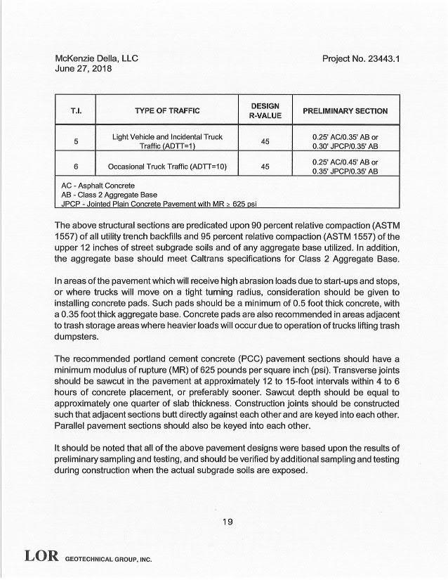
1 Project Specific Water Quality Management Plan A Template for Projects located within the Santa Ana Watershed Region of Riverside County Project Title: Canyon Steel Industrial Building Development No: 4280 Patterson Avenue, Perris, CA Design Review/Case No: DPR Contact Information: Preliminary Final Original Date Prepared: August 208 Revision Date(s): October 208 Prepared for Compliance with Regional Board Order No. R Template revised June 30, Prepared for: McKenzie Della, LLC Orangewood Court Grand Terrace, CA 9233 Prepared by: alued Engineering, Inc Jeff Meiter, President 600 N. Mountain Avenue, Suite C02 Upland, CA 9786


2 A Brief Introduction This Project-Specific WQMP Template for the Santa Ana Region has been prepared to help guide you in documenting compliance for your project. Because this document has been designed to specifically document compliance, you will need to utilize the WQMP Guidance Document as your how-to manual to help guide you through this process. Both the Template and Guidance Document go hand-in-hand, and will help facilitate a well prepared Project-Specific WQMP. Below is a flowchart for the layout of this Template that will provide the steps required to document compliance. Section A Project and Site Information Section B Optimize Site Utilization Section C Delineate Drainage Management Areas (DMAs) Section F Hydromodification Section E Alternative Compliance Section D Implement LID BMPs Section G Source Control BMPs Section H Construction Plan Checklist Section I Operation, Maintenance, and Funding - 2 -
3 OWNER S CERTIFICATION This Project-Specific Water Quality Management Plan (WQMP) has been prepared for McKenzie Della, LLC by alued Engineering, Inc for the Canyon Steel Industrial Building project. This WQMP is intended to comply with the requirements of City of Perris for 94 which includes the requirement for the preparation and implementation of a Project-Specific WQMP. The undersigned, while owning the property/project described in the preceding paragraph, shall be responsible for the implementation and funding of this WQMP and will ensure that this WQMP is amended as appropriate to reflect up-to-date conditions on the site. In addition, the property owner accepts responsibility for interim operation and maintenance of Stormwater BMPs until such time as this responsibility is formally transferred to a subsequent owner. This WQMP will be reviewed with the facility operator, facility supervisors, employees, tenants, maintenance and service contractors, or any other party (or parties) having responsibility for implementing portions of this WQMP. At least one copy of this WQMP will be maintained at the project site or project office in perpetuity. The undersigned is authorized to certify and to approve implementation of this WQMP. The undersigned is aware that implementation of this WQMP is enforceable under City of Perris Water Quality Ordinance (Municipal Code Section94). "I, the undersigned, certify under penalty of law that the provisions of this WQMP have been reviewed and accepted and that the WQMP will be transferred to future successors in interest." Owner s Signature Date Owner s Printed Name Owner s Title/Position PREPARER S CERTIFICATION The selection, sizing and design of stormwater treatment and other stormwater quality and quantity control measures in this plan meet the requirements of Regional Water Quality Control Board Order No. R and any subsequent amendments thereto. Preparer s Signature Date Preparer s Printed Name Preparer s Title/Position Preparer s Licensure: - 3 -
4 Table of Contents Section A: Project and Site Information... 6 A. Maps and Site Plans... 7 A.2 Identify Receiving Waters... 7 A.3 Additional Permits/Approvals required for the Project:... 8 Section B: Optimize Site Utilization (LID Principles)... 9 Section C: Delineate Drainage Management Areas (DMAs)... Section D: Implement LID BMPs... 3 D. Infiltration Applicability... 3 D.2 Harvest and Use Assessment... 4 D.3 Bioretention and Biotreatment Assessment... 6 D.4 Feasibility Assessment Summaries... 7 D.5 LID BMP Sizing... 8 Section E: Alternative Compliance (LID Waiver Program) E. Identify Pollutants of Concern... 2 E.2 Stormwater Credits E.3 Sizing Criteria E.4 Treatment Control BMP Selection Section F: Hydromodification F. Hydrologic Conditions of Concern (HCOC) Analysis F.2 HCOC Mitigation Section G: Source Control BMPs Section H: Construction Plan Checklist Section I: Operation, Maintenance and Funding
5 List of Tables Table A. Identification of Receiving Waters... 7 Table A.2 Other Applicable Permits... 8 Table C. DMA Classifications... Table C.2 Type A, Self-Treating Areas... Table C.3 Type B, Self-Retaining Areas... Table C.4 Type C, Areas that Drain to Self-Retaining Areas... Table C.5 Type D, Areas Draining to BMPs... 2 Table D. Infiltration Feasibility... 3 Table D.2 LID Prioritization Summary Matrix... 7 Table D.3 DC Calculations for LID BMPs... 8 Table E. Potential Pollutants by Land Use Type... 2 Table E.2 Water Quality Credits Table E.3 Treatment Control BMP Sizing Table E.4 Treatment Control BMP Selection Table F. Hydrologic Conditions of Concern Summary Table G. Permanent and Operational Source Control Measures Table H. Construction Plan Cross-reference List of Appendices Appendix : Maps and Site Plans Appendix 2: Construction Plans Appendix 3: Soils Information... 3 Appendix 4: Historical Site Conditions Appendix 5: LID Infeasibility Appendix 6: BMP Design Details Appendix 7: Hydromodification Appendix 8: Source Control Appendix 9: O&M Appendix 0: Educational Materials
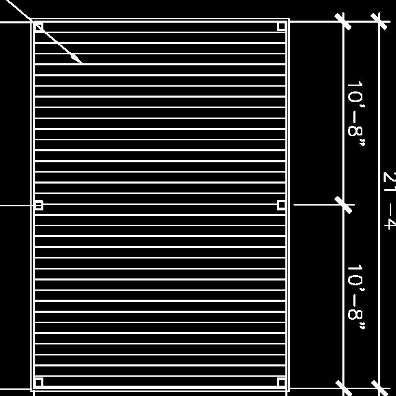
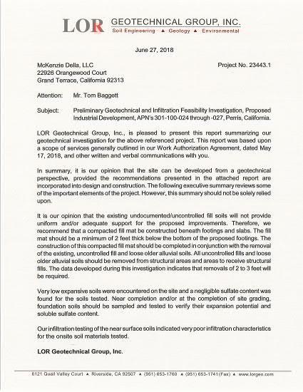
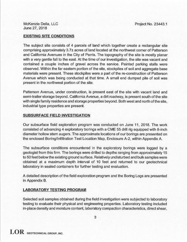
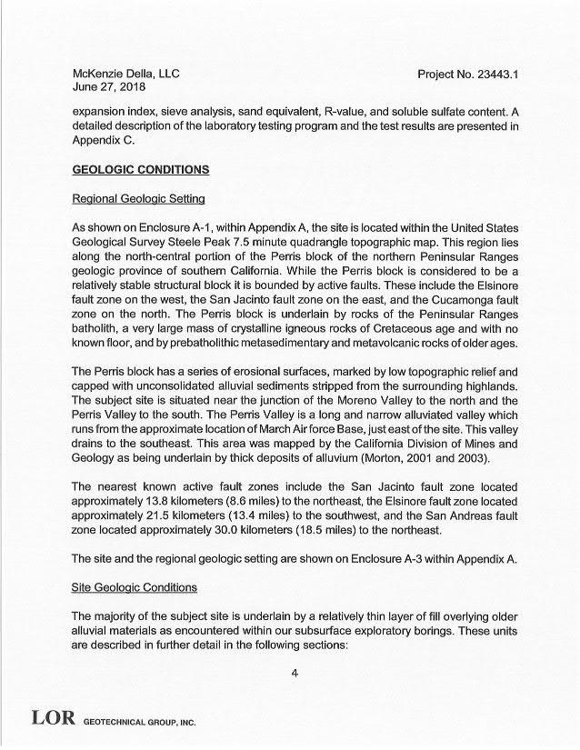
6 Section A: Project and Site Information PROJECT INFORMATION Type of Project: Industrial Planning Area: Perris Planning Area Community Name: Perris alley Development Name: Planning Area PROJECT LOCATION Latitude & Longitude (DMS): , Project Watershed and Sub-Watershed: Santa Ana River Watershed & Jacinto Sub-Watersed Gross Acres: 3.69 APN(s): , , , Map Book and Page No.: Thomas Bros. Map, Page 747 PROJECT CHARACTERISTICS Proposed or Potential Land Use(s) Industrial Warehouse Proposed or Potential SIC Code(s) 505 Area of Impervious Project Footprint (SF) 93,325 Total Area of proposed Impervious Surfaces within the Project Footprint (SF)/or Replacement 93,325 Does the project consist of offsite road improvements? Y N Does the project propose to construct unpaved roads? Y N Is the project part of a larger common plan of development (phased project)? Y N EXISTING SITE CHARACTERISTICS Total area of existing Impervious Surfaces within the Project limits Footprint (SF) 0 Is the project located within any MSHCP Criteria Cell? Y N If so, identify the Cell number: Are there any natural hydrologic features on the project site? Y N Is a Geotechnical Report attached? Y N If no Geotech. Report, list the NRCS soils type(s) present on the site (A, B, C and/or D) A What is the Water Quality Design Storm Depth for the project? 0.60 McKenzie Della, LLC proposes to develop 3.83 acres of existing vacant land in the City of Perris, CA, bounded by Patterson Avenue on the east, California Avenue on the south and commercial properties to the west and north. The developed site will reduce the total acreage from 3.83 acres to 3.59 acres by moving additional right-of-way dedications along Patterson Avenue and California Avenue to accommodate public sidewalks and landscaping. The project proposes to construct a 22,920 square-foot industrial building, a 00 x 20 pad for crane bays (two total) and a 00 x 20 concrete slab for material drop off. Additional improvements will include parking, landscape, bioretention basins and hardscape improvements. Parkway improvements are proposed for the frontage streets of Patterson Avenue and California Avenue. The improvements consist of sidewalk, landscape and driveway approaches. Both streets will also involve constructing curb and gutter to the ultimate street width (curb to curb) per City standards for Patterson Avenue and California Street, 66 and 60, respectively
7 The proposed site can be broken down into two distinct drainage management areas, DMA and DMA 2. DMA will capture the stormwater from the southern portion of the development. Stormwater runoff produces from subarea A will be treated through bioretention basins along the southeastern portion of the development between the proposed parking and right-of-way dedications. DMA 2 will capture stormwater from the northerly portion of the proposed development. The stormwater will be routed via curb and gutters, gravel swales and curb openings. Both DMA's will have emergency overflow outlets to the adjacent public streets along Patterson Avenue. A. Maps and Site Plans When completing your Project-Specific WQMP, include a map of the local vicinity and existing site. In addition, include all grading, drainage, landscape/plant palette and other pertinent construction plans in Appendix 2. At a minimum, your WQMP Site Plan should include the following: Drainage Management Areas Proposed Structural BMPs Drainage Path Drainage Infrastructure, Inlets, Overflows Source Control BMPs Buildings, Roof Lines, Downspouts Impervious Surfaces Standard Labeling BMP Locations (Lat/Long) Use your discretion on whether or not you may need to create multiple sheets or can appropriately accommodate these features on one or two sheets. Keep in mind that the Co-Permittee plan reviewer must be able to easily analyze your project utilizing this template and its associated site plans and maps. A.2 Identify Receiving Waters Using Table A. below, list in order of upstream to downstream, the receiving waters that the project site is tributary to. Continue to fill each row with the Receiving Water s 303(d) listed impairments (if any), designated beneficial uses, and proximity, if any, to a RARE beneficial use. Include a map of the receiving waters in Appendix. Table A. Identification of Receiving Waters Receiving Waters EPA Approved 303(d) List Impairments Designated Beneficial Uses Proximity to RARE Beneficial Use Perris alley Storm Drain San Jacinto River, Reach 3 Canyon Lake San Jacinto River, Reach Lake Elsinore None None None None Nutrients & Pathogens None Nutrients, Organic, PCB, Sediment, Unknown Toxicity Agr, GWR, REC, REC2, Warm, Wild Mun, Agr, Gwr, REC, REC2, Warm, Wild Agr, GWR, REC, REC2, Warm, Wild REC, REC2, Warm, Wild None None None None - 7 -
8 A.3 Additional Permits/Approvals required for the Project: Table A.2 Other Applicable Permits Agency Permit Required State Department of Fish and Game, 602 Streambed Alteration Agreement Y N State Water Resources Control Board, Clean Water Act (CWA) Section 40 Water Quality Cert. Y N US Army Corps of Engineers, CWA Section 404 Permit Y N US Fish and Wildlife, Endangered Species Act Section 7 Biological Opinion Y N Statewide Construction General Permit Coverage Y N Statewide Industrial General Permit Coverage (Dependent on Tenant) Y N Western Riverside MSHCP Consistency Approval (e.g., JPR, DBESP) Y N Other (please list in the space below as required) City of Perris Grading Permit Other (please list in the space below as required) City of Perris Building Permit Y N Y N If yes is answered to any of the questions above, the Co-Permittee may require proof of approval/coverage from those agencies as applicable including documentation of any associated requirements that may affect this Project-Specific WQMP
9 Section B: Optimize Site Utilization (LID Principles) Review of the information collected in Section A will aid in identifying the principal constraints on site design and selection of LID BMPs as well as opportunities to reduce imperviousness and incorporate LID Principles into the site and landscape design. For example, constraints might include impermeable soils, high groundwater, groundwater pollution or contaminated soils, steep slopes, geotechnical instability, high-intensity land use, heavy pedestrian or vehicular traffic, utility locations or safety concerns. Opportunities might include existing natural areas, low areas, oddly configured or otherwise unbuildable parcels, easements and landscape amenities including open space and buffers (which can double as locations for bioretention BMPs), and differences in elevation (which can provide hydraulic head). Prepare a brief narrative for each of the site optimization strategies described below. This narrative will help you as you proceed with your LID design and explain your design decisions to others. The 200 Santa Ana MS4 Permit further requires that LID Retention BMPs (Infiltration Only or Harvest and Use) be used unless it can be shown that those BMPs are infeasible. Therefore, it is important that your narrative identify and justify if there are any constraints that would prevent the use of those categories of LID BMPs. Similarly, you should also note opportunities that exist which will be utilized during project design. Upon completion of identifying Constraints and Opportunities, include these on your WQMP Site plan in Appendix. Consideration of highest and best use of the discharge should also be considered. For example, Lake Elsinore is evaporating faster than runoff from natural precipitation can recharge it. Requiring infiltration of 85% of runoff events for projects tributary to Lake Elsinore would only exacerbate current water quality problems associated with Pollutant concentration due to lake water evaporation. In cases where rainfall events have low potential to recharge Lake Elsinore (i.e. no hydraulic connection between groundwater to Lake Elsinore, or other factors), requiring infiltration of Urban Runoff from projects is counterproductive to the overall watershed goals. Project proponents, in these cases, would be allowed to discharge Urban Runoff, provided they used equally effective filtration-based BMPs. Site Optimization The following questions are based upon Section 3.2 of the WQMP Guidance Document. Review of the WQMP Guidance Document will help you determine how best to optimize your site and subsequently identify opportunities and/or constraints, and document compliance. Did you identify and preserve existing drainage patterns? If so, how? If not, why? Yes. Existing stormwater runoff generally flows from west to east at average grades of % to 3%. The proposed drainage will hold the general drainage pattern by capturing runoff from the west side of the development to the easterly portion of the property. Did you identify and protect existing vegetation? If so, how? If not, why? No. The existing site consists of undeveloped native earth with poor vegetative cover. The little vegetation present in the existing condition is mainly annual grass/weeds. This vegetation will not be preserved
10 Did you identify and preserve natural infiltration capacity? If so, how? If not, why? No. Natural infiltration capacity is very low and bioretention basins will be used to treat stormwater runoff produced from developing the site. Did you identify and minimize impervious area? If so, how? If not, why? Yes. Approximately 4% of the developed site will be a pervious surface. There are two pervious surfaces that will be present on-site, landscaping (22%) and native earth (9%). Did you identify and disperse runoff to adjacent pervious areas? If so, how? If not, why? Yes. Roof drains will be dispersed on landscaping and then will drain to landscape areas where grading will direct the stormwater runoff into the proposed bioretention basins
11 Section C: Delineate Drainage Management Areas (DMAs) Utilizing the procedure in Section 3.3 of the WQMP Guidance Document which discusses the methods of delineating and mapping your project site into individual DMAs, complete Table C. below to appropriately categorize the types of classification (e.g., Type A, Type B, etc.) per DMA for your project site. Upon completion of this table, this information will then be used to populate and tabulate the corresponding tables for their respective DMA classifications. Table C. DMA Classifications DMA Name or ID Surface Type(s) 2 Area (Sq. Ft.) DMA Type DMA Landscape, Roofs, PCC 75,490 D DMA 2 Landscape, PCC, Native 80,740 D Reference Table 2- in the WQMP Guidance Document to populate this column 2 If multi-surface provide back-up Table C.2 Type A, Self-Treating Areas DMA Name or ID Area (Sq. Ft.) Stabilization Type Irrigation Type (if any) N/A N/A N/A N/A Table C.3 Type B, Self-Retaining Areas Self-Retaining Area DMA Name/ ID Post-project surface type Area (square feet) Storm Type C DMAs that are draining to the Self-Retaining Area Depth [C] from Table C.4 (inches) DMA Name / = [A] [B] ID [C] [D] Required Retention Depth (inches) N/A N/A N/A N/A N/A N/A N/A Table C.4 Type C, Areas that Drain to Self-Retaining Areas [ ] [ ] [ ] = [ ] + [ ] DMA Receiving Self-Retaining DMA DMA Name/ ID Area (square feet) Post-project surface type Impervious fraction Product Area (square feet) Ratio [A] [B] [C] = [A] x [B] DMA name /ID [D] [C]/[D] N/A N/A N/A N/A N/A N/A N/A N/A - -
12 Table C.5 Type D, Areas Draining to BMPs DMA Name or ID DMA DMA 2 BMP Name or ID BIORETENTION BASIN BIORETENTION BASIN Note: More than one drainage management area can drain to a single LID BMP, however, one drainage management area may not drain to more than one BMP
13 Section D: Implement LID BMPs D. Infiltration Applicability Is there an approved downstream Highest and Best Use for stormwater runoff (see discussion in Chapter of the WQMP Guidance Document for further details)? Y N If yes has been checked, Infiltration BMPs shall not be used for the site; proceed to section D.3 If no, continue working through this section to implement your LID BMPs. It is recommended that you contact your Co-Permittee to verify whether or not your project discharges to an approved downstream Highest and Best Use feature. Geotechnical Report A Geotechnical Report or Phase I Environmental Site Assessment may be required by the Co-permittee to confirm present and past site characteristics that may affect the use of Infiltration BMPs. In addition, the Co-Permittee, at their discretion, may not require a geotechnical report for small projects as described in Chapter 2 of the WQMP Guidance Document. If a geotechnical report has been prepared, include it in Appendix 3. In addition, if a Phase I Environmental Site Assessment has been prepared, include it in Appendix 4. Is this project classified as a small project consistent with the requirements of Chapter 2 of the WQMP Guidance Document? Y N Infiltration Feasibility Table D. below is meant to provide a simple means of assessing which DMAs on your site support Infiltration BMPs and is discussed in the WQMP Guidance Document in Chapter Check the appropriate box for each question and then list affected DMAs as applicable. If additional space is needed, add a row below the corresponding answer. Table D. Infiltration Feasibility Does the project site YES NO have any DMAs with a seasonal high groundwater mark shallower than 0 feet? X If Yes, list affected DMAs: have any DMAs located within 00 feet of a water supply well? X If Yes, list affected DMAs: have any areas identified by the geotechnical report as posing a public safety risk where infiltration of stormwater X could have a negative impact? If Yes, list affected DMAs: have measured in-situ infiltration rates of less than.6 inches / hour? X If Yes, list affected DMAs: ALL have significant cut and/or fill conditions that would preclude in-situ testing of infiltration rates at the final X infiltration surface? If Yes, list affected DMAs: geotechnical report identify other site-specific factors that would preclude effective and safe infiltration? X Describe here: If you answered Yes to any of the questions above for any DMA, Infiltration BMPs should not be used for those DMAs and you should proceed to the assessment for Harvest and Use below
14 D.2 Harvest and Use Assessment Please check what applies: Reclaimed water will be used for the non-potable water demands for the project. Downstream water rights may be impacted by Harvest and Use as approved by the Regional Board (verify with the Copermittee). The Design Capture olume will be addressed using Infiltration Only BMPs. In such a case, Harvest and Use BMPs are still encouraged, but it would not be required if the Design Capture olume will be infiltrated or evapotranspired. If any of the above boxes have been checked, Harvest and Use BMPs need not be assessed for the site. If none of the above criteria applies, follow the steps below to assess the feasibility of irrigation use, toilet use and other non-potable uses (e.g., industrial use). Irrigation Use Feasibility Complete the following steps to determine the feasibility of harvesting stormwater runoff for Irrigation Use BMPs on your site: Step : Step 2: Step 3: Step 4: Step 5: Identify the total area of irrigated landscape on the site, and the type of landscaping used. Total Area of Irrigated Landscape: Type of Landscaping (Conservation Design or Active Turf): Identify the planned total of all impervious areas on the proposed project from which runoff might be feasibly captured and stored for irrigation use. Depending on the configuration of buildings and other impervious areas on the site, you may consider the site as a whole, or parts of the site, to evaluate reasonable scenarios for capturing and storing runoff and directing the stored runoff to the potential use(s) identified in Step above. Total Area of Impervious Surfaces: Cross reference the Design Storm depth for the project site (see Exhibit A of the WQMP Guidance Document) with the left column of Table 2-3 in Chapter 2 to determine the minimum area of Effective Irrigated Area per Tributary Impervious Area (EIATIA). Enter your EIATIA factor: Multiply the unit value obtained from Step 3 by the total of impervious areas from Step 2 to develop the minimum irrigated area that would be required. Minimum required irrigated area: Determine if harvesting stormwater runoff for irrigation use is feasible for the project by comparing the total area of irrigated landscape (Step ) to the minimum required irrigated area (Step 4). Minimum required irrigated area (Step 4) Available Irrigated Landscape (Step ) - 4 -
15 Toilet Use Feasibility Complete the following steps to determine the feasibility of harvesting stormwater runoff for toilet flushing uses on your site: Step : Step 2: Identify the projected total number of daily toilet users during the wet season, and account for any periodic shut downs or other lapses in occupancy: Projected Number of Daily Toilet Users: Project Type: Identify the planned total of all impervious areas on the proposed project from which runoff might be feasibly captured and stored for toilet use. Depending on the configuration of buildings and other impervious areas on the site, you may consider the site as a whole, or parts of the site, to evaluate reasonable scenarios for capturing and storing runoff and directing the stored runoff to the potential use(s) identified in Step above. Total Area of Impervious Surfaces: Step 3: Enter the Design Storm depth for the project site (see Exhibit A) into the left column of Table 2-2 in Chapter 2 to determine the minimum number or toilet users per tributary impervious acre (TUTIA). Step 4: Step 5: Enter your TUTIA factor: Multiply the unit value obtained from Step 3 by the total of impervious areas from Step 2 to develop the minimum number of toilet users that would be required. Minimum number of toilet users: Determine if harvesting stormwater runoff for toilet flushing use is feasible for the project by comparing the Number of Daily Toilet Users (Step ) to the minimum required number of toilet users (Step 4). Minimum required Toilet Users (Step 4) Projected number of toilet users (Step ) Other Non-Potable Use Feasibility Are there other non-potable uses for stormwater runoff on the site (e.g. industrial use)? See Chapter 2 of the Guidance for further information. If yes, describe below. If no, write N/A. Step : Step 2: Identify the projected average daily non-potable demand, in gallons per day, during the wet season and accounting for any periodic shut downs or other lapses in occupancy or operation. Average Daily Demand: Identify the planned total of all impervious areas on the proposed project from which runoff might be feasibly captured and stored for the identified non-potable use. Depending on the configuration of buildings and other impervious areas on the site, you may consider the site as a whole, or parts of the site, to evaluate reasonable scenarios for capturing and storing runoff and directing the stored runoff to the potential use(s) identified in Step above. Total Area of Impervious Surfaces: - 5 -
16 Step 3: Enter the Design Storm depth for the project site (see Exhibit A) into the left column of Table 2-4 in Chapter 2 to determine the minimum demand for non-potable uses per tributary impervious acre. Step 4: Step 5: Enter the factor from Table 2-4: Multiply the unit value obtained from Step 3 by the total of impervious areas from Step 2 to develop the minimum number of gallons per day of non-potable use that would be required. Minimum required use: Determine if harvesting stormwater runoff for other non-potable use is feasible for the project by comparing the projected average daily use (Step ) to the minimum required non-potable use (Step 4). Minimum required non-potable use (Step 4) Projected average daily use (Step ) If Irrigation, Toilet and Other Use feasibility anticipated demands are less than the applicable minimum values, Harvest and Use BMPs are not required and you should proceed to utilize LID Bioretention and Biotreatment per Section of the WQMP Guidance Document. D.3 Bioretention and Biotreatment Assessment Other LID Bioretention and Biotreatment BMPs as described in Chapter of the WQMP Guidance Document are feasible on nearly all development sites with sufficient advance planning. Select one of the following: LID Bioretention/Biotreatment BMPs will be used for some or all DMAs of the project as noted below in Section D.4 (note the requirements of Section in the WQMP Guidance Document). A site-specific analysis demonstrating the technical infeasibility of all LID BMPs has been performed and is included in Appendix 5. If you plan to submit an analysis demonstrating the technical infeasibility of LID BMPs, request a pre-submittal meeting with the Copermittee to discuss this option. Proceed to Section E to document your alternative compliance measures
17 D.4 Feasibility Assessment Summaries From the Infiltration, Harvest and Use, Bioretention and Biotreatment Sections above, complete Table D.2 below to summarize which LID BMPs are technically feasible, and which are not, based upon the established hierarchy. Table D.2 LID Prioritization Summary Matrix DMA Name/ID DMA DMA 2 LID BMP Hierarchy. Infiltration 2. Harvest and use 3. Bioretention 4. Biotreatment No LID (Alternative Compliance) For those DMAs where LID BMPs are not feasible, provide a brief narrative below summarizing why they are not feasible, include your technical infeasibility criteria in Appendix 5, and proceed to Section E below to document Alternative Compliance measures for those DMAs. Recall that each proposed DMA must pass through the LID BMP hierarchy before alternative compliance measures may be considered. *Entire site will treat stormwater through bioretention basins* - 7 -
18 D.5 LID BMP Sizing Each LID BMP must be designed to ensure that the Design Capture olume will be addressed by the selected BMPs. First, calculate the Design Capture olume for each LID BMP using the BMP worksheet in Appendix F of the LID BMP Design Handbook. Second, design the LID BMP to meet the required BMP using a method approved by the Copermittee. Utilize the worksheets found in the LID BMP Design Handbook or consult with your Copermittee to assist you in correctly sizing your LID BMPs. Complete Table D.3 below to document the Design Capture olume and the Proposed olume for each LID BMP. Provide the completed design procedure sheets for each LID BMP in Appendix 6. You may add additional rows to the table below as needed. Table D.3 DC Calculations for LID BMPs Post- DMA Type/ID DMA Area (square feet) Project Surface Type Effective Impervious Fraction, I f DMA Runoff Factor DMA Areas x Runoff Factor [A] [B] [C] [A] x [C] D/a 570 Landscape D/b 760 PCC/Roof Enter BMP Name / Identifier Here Design Storm Depth (in) DMA Design Capture olume, BMP (cubic feet) Proposed olume on Plans (cubic feet) A T = Σ[A] 2980 Σ= [D] 6986 [E] 0.60 [F] = [D]x[E] [G] 90 [B], [C] is obtained as described in Section 2.3. of the WQMP Guidance Document [E] is obtained from Exhibit A in the WQMP Guidance Document [G] is obtained from a design procedure sheet, such as in LID BMP Design Handbook and placed in Appendix 6 DMA Type/ID DMA Area (square feet) Post- Project Surface Type Effective Impervious Fraction, I f DMA Runoff Factor DMA Areas x Runoff Factor [A] [B] [C] [A] x [C] D/2a 2545 Landscape D/2b 8765 PCC/AC Enter BMP Name / Identifier Here Design Storm Depth (in) DMA 2 Design Capture olume, BMP (cubic feet) Proposed olume on Plans (cubic feet) A T = Σ[A] 30 Σ= [D] [E] 0.60 [F] = [D]x[E] [G]
19 DMA Type/ID DMA Area (square feet) Post- Project Surface Type Effective Impervious Fraction, I f DMA Runoff Factor DMA Areas x Runoff Factor [A] [B] [C] [A] x [C] Enter BMP Name / Identifier Here DMA 3 D/3a 2740 Landscape D/3b 8205 PCC/Roof Design Storm Depth (in) Design Capture olume, BMP (cubic feet) Proposed olume on Plans (cubic feet) A T = Σ[A] Σ= [D] [E] [F] = [D]x[E] 2 [G] DMA Type/ID DMA Area (square feet) D/4a Post- Project Surface Type Effective Impervious Fraction, I f DMA Runoff Factor DMA Areas x Runoff Factor [A] [B] [C] [A] x [C] Natural (A) D/4b 7895 Landscape D/4c 630 PCC/Roof Enter BMP Name / Identifier Here Design Storm Depth (in) DMA 4 Design Capture olume, BMP (cubic feet) Proposed olume on Plans (cubic feet) A T = Σ[A] Σ= [D] [E] [F] = [D]x[E] 2 [G]
20 Section E: Alternative Compliance (LID Waiver Program) LID BMPs are expected to be feasible on virtually all projects. Where LID BMPs have been demonstrated to be infeasible as documented in Section D, other Treatment Control BMPs must be used (subject to LID waiver approval by the Copermittee). Check one of the following Boxes: LID Principles and LID BMPs have been incorporated into the site design to fully address all Drainage Management Areas. No alternative compliance measures are required for this project and thus this Section is not required to be completed. - Or - The following Drainage Management Areas are unable to be addressed using LID BMPs. A sitespecific analysis demonstrating technical infeasibility of LID BMPs has been approved by the Co- Permittee and included in Appendix 5. Additionally, no downstream regional and/or sub-regional LID BMPs exist or are available for use by the project. The following alternative compliance measures on the following pages are being implemented to ensure that any pollutant loads expected to be discharged by not incorporating LID BMPs, are fully mitigated
21 E. Identify Pollutants of Concern Utilizing Table A. from Section A above which noted your project s receiving waters and their associated EPA approved 303(d) listed impairments, cross reference this information with that of your selected Priority Development Project Category in Table E. below. If the identified General Pollutant Categories are the same as those listed for your receiving waters, then these will be your Pollutants of Concern and the appropriate box or boxes will be checked on the last row. The purpose of this is to document compliance and to help you appropriately plan for mitigating your Pollutants of Concern in lieu of implementing LID BMPs. Table E. Potential Pollutants by Land Use Type Priority Project Categories and/or Project Features (check those that apply) Detached Residential Development Attached Residential Development Commercial/Industrial Development Automotive Repair Shops Restaurants (>5,000 ft 2 ) Hillside Development (>5,000 ft 2 ) Parking Lots (>5,000 ft 2 ) Development General Pollutant Categories Toxic Bacterial Indicators Metals Nutrients Pesticides Organic Compounds Sediments Trash & Debris P N P P N P P P Oil Grease P N P P N P P P (2) P (3) P P () P () P (5) P () P P N P N N P (4, 5) N P P P N N N N N P P P N P P N P P P P (6) P P () P () P (4) P () P P Retail Gasoline Outlets N P N N P N P P Project Priority Pollutant(s) of Concern P = Potential N = Not Potential () A potential Pollutant if non-native landscaping exists or is proposed onsite; otherwise not expected (2) A potential Pollutant if the project includes uncovered parking areas; otherwise not expected (3) A potential Pollutant is land use involving animal waste (4) Specifically petroleum hydrocarbons (5) Specifically solvents (6) Bacterial indicators are routinely detected in pavement runoff & - 2 -
22 E.2 Stormwater Credits Projects that cannot implement LID BMPs but nevertheless implement smart growth principles are potentially eligible for Stormwater Credits. Utilize Table 3-8 within the WQMP Guidance Document to identify your Project Category and its associated Water Quality Credit. If not applicable, write N/A. Table E.2 Water Quality Credits Qualifying Project Categories Credit Percentage 2 Total Credit Percentage Cannot Exceed 50% 2 Obtain corresponding data from Table 3-8 in the WQMP Guidance Document E.3 Sizing Criteria After you appropriately considered Stormwater Credits for your project, utilize Table E.3 below to appropriately size them to the DC, or Design Flow Rate, as applicable. Please reference Chapter of the WQMP Guidance Document for further information. Table E.3 Treatment Control BMP Sizing DMA Post- Area Project (square Surface feet) Type DMA Type/ID Effective Impervious Fraction, I f DMA Runoff Factor DMA Area x Runoff Factor [A] [B] [C] [A] x [C] Enter BMP Name / Identifier Here Design Storm Depth (in) Minimum Design Capture olume or Design Flow Rate (cubic feet or cfs) Total Storm Water Credit % Reduction Proposed olume or Flow on Plans (cubic feet or cfs) A T = Σ[A] Σ= [D] [E] [F] = [D]x[E] [G] [F] X (-[H]) [I] [B], [C] is obtained as described in Section 2.3. from the WQMP Guidance Document [E] is for Flow-Based Treatment Control BMPs [E] =.2, for olume-based Control Treatment BMPs, [E] obtained from Exhibit A in the WQMP Guidance Document [G] is for Flow-Based Treatment Control BMPs [G] = 43,560, for olume-based Control Treatment BMPs, [G] = 2 [H] is from the Total Credit Percentage as Calculated from Table E.2 above [I] as obtained from a design procedure sheet from the BMP manufacturer and should be included in Appendix
23 E.4 Treatment Control BMP Selection Treatment Control BMPs typically provide proprietary treatment mechanisms to treat potential pollutants in runoff, but do not sustain significant biological processes. Treatment Control BMPs must have a removal efficiency of a medium or high effectiveness as quantified below: High: equal to or greater than 80% removal efficiency Medium: between 40% and 80% removal efficiency Such removal efficiency documentation (e.g., studies, reports, etc.) as further discussed in Chapter of the WQMP Guidance Document, must be included in Appendix 6. In addition, ensure that proposed Treatment Control BMPs are properly identified on the WQMP Site Plan in Appendix. Table E.4 Treatment Control BMP Selection Selected Treatment Priority Pollutant(s) of Concern to Mitigate 2 Removal Efficiency Control BMP Name or ID Percentage 3 Treatment Control BMPs must not be constructed within Receiving Waters. In addition, a proposed Treatment Control BMP may be listed more than once if they possess more than one qualifying pollutant removal efficiency. 2 Cross Reference Table E. above to populate this column. 3 As documented in a Co-Permittee Approved Study and provided in Appendix
24 Section F: Hydromodification F. Hydrologic Conditions of Concern (HCOC) Analysis Once you have determined that the LID design is adequate to address water quality requirements, you will need to assess if the proposed LID Design may still create a HCOC. Review Chapters 2 and 3 (including Figure 3-7) of the WQMP Guidance Document to determine if your project must mitigate for Hydromodification impacts. If your project meets one of the following criteria which will be indicated by the check boxes below, you do not need to address Hydromodification at this time. However, if the project does not qualify for Exemptions, 2 or 3, then additional measures must be added to the design to comply with HCOC criteria. This is discussed in further detail below in Section F.2. HCOC EXEMPTION : The Priority Development Project disturbs less than one acre. The Copermittee has the discretion to require a Project-Specific WQMP to address HCOCs on projects less than one acre on a case by case basis. The disturbed area calculation should include all disturbances associated with larger common plans of development. Does the project qualify for this HCOC Exemption? Y N If Yes, HCOC criteria do not apply. HCOC EXEMPTION 2: The volume and time of concentration of storm water runoff for the postdevelopment condition is not significantly different from the pre-development condition for a 2-year return frequency storm (a difference of 5% or less is considered insignificant) using one of the following methods to calculate: Riverside County Hydrology Manual Technical Release 55 (TR-55): Urban Hydrology for Small Watersheds (NRCS 986), or derivatives thereof, such as the Santa Barbara Urban Hydrograph Method Other methods acceptable to the Co-Permittee Does the project qualify for this HCOC Exemption? Y N If Yes, report results in Table F. below and provide your substantiated hydrologic analysis in Appendix 7. Table F. Hydrologic Conditions of Concern Summary Time of Concentration olume (Cubic Feet) 2 year 24 hour Pre-condition Post-condition % Difference Time of concentration is defined as the time after the beginning of the rainfall when all portions of the drainage basin are contributing to flow at the outlet
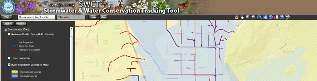
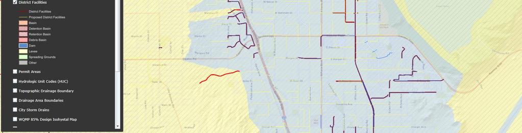
25 HCOC EXEMPTION 3: All downstream conveyance channels to an adequate sump (for example, Prado Dam, Lake Elsinore, Canyon Lake, Santa Ana River, or other lake, reservoir or naturally erosion resistant feature) that will receive runoff from the project are engineered and regularly maintained to ensure design flow capacity; no sensitive stream habitat areas will be adversely affected; or are not identified on the Co-Permittees Hydromodification Susceptibility Maps. Does the project qualify for this HCOC Exemption? Y N If Yes, HCOC criteria do not apply and note below which adequate sump applies to this HCOC qualifier: F.2 HCOC Mitigation If none of the above HCOC Exemption Criteria are applicable, HCOC criteria is considered mitigated if they meet one of the following conditions: a. Additional LID BMPS are implemented onsite or offsite to mitigate potential erosion or habitat impacts as a result of HCOCs. This can be conducted by an evaluation of site-specific conditions utilizing accepted professional methodologies published by entities such as the California Stormwater Quality Association (CASQA), the Southern California Coastal Water Research Project (SCCRWP), or other Co-Permittee approved methodologies for site-specific HCOC analysis. b. The project is developed consistent with an approved Watershed Action Plan that addresses HCOC in Receiving Waters. c. Mimicking the pre-development hydrograph with the post-development hydrograph, for a 2-year return frequency storm. Generally, the hydrologic conditions of concern are not significant, if the post-development hydrograph is no more than 0% greater than pre-development hydrograph. In cases where excess volume cannot be infiltrated or captured and reused, discharge from the site must be limited to a flow rate no greater than 0% of the pre-development 2-year peak flow. Be sure to include all pertinent documentation used in your analysis of the items a, b or c in Appendix 7. ** This site is located within the mapped HCOC exemption area as presented in the Riverside Co. geodatabase. This map was approved April 0, 207**
26 Section G: Source Control BMPs Source control BMPs include permanent, structural features that may be required in your project plans such as roofs over and berms around trash and recycling areas and Operational BMPs, such as regular sweeping and housekeeping, that must be implemented by the site s occupant or user. The MEP standard typically requires both types of BMPs. In general, Operational BMPs cannot be substituted for a feasible and effective permanent BMP. Using the Pollutant Sources/Source Control Checklist in Appendix 8, review the following procedure to specify Source Control BMPs for your site:. Identify Pollutant Sources: Review Column in the Pollutant Sources/Source Control Checklist. Check off the potential sources of Pollutants that apply to your site. 2. Note Locations on Project-Specific WQMP Exhibit: Note the corresponding requirements listed in Column 2 of the Pollutant Sources/Source Control Checklist. Show the location of each Pollutant source and each permanent Source Control BMP in your Project-Specific WQMP Exhibit located in Appendix. 3. Prepare a Table and Narrative: Check off the corresponding requirements listed in Column 3 in the Pollutant Sources/Source Control Checklist. In the left column of Table G. below, list each potential source of runoff Pollutants on your site (from those that you checked in the Pollutant Sources/Source Control Checklist). In the middle column, list the corresponding permanent, Structural Source Control BMPs (from Columns 2 and 3 of the Pollutant Sources/Source Control Checklist) used to prevent Pollutants from entering runoff. Add additional narrative in this column that explains any special features, materials or methods of construction that will be used to implement these permanent, Structural Source Control BMPs. 4. Identify Operational Source Control BMPs: To complete your table, refer once again to the Pollutant Sources/Source Control Checklist. List in the right column of your table the Operational BMPs that should be implemented as long as the anticipated activities continue at the site. Copermittee stormwater ordinances require that applicable Source Control BMPs be implemented; the same BMPs may also be required as a condition of a use permit or other revocable Discretionary Approval for use of the site. Table G. Permanent and Operational Source Control Measures Potential Sources of Runoff pollutants Permanent Structural Source Control BMPs Operational Source Control BMPs Trash & Debris Oils & Greases Trash Enclosure Roof & Cover Proposed Bioretention Basins Weekly Sweeping & Housekeeping Weekly Inspection of Parking Lots Sediment Proposed Bioretention Basins Weekly Sweeping Metals Bacteria & iruses Nutrients Oxygen Demanding Substances Proposed Bioretention Basins Proposed Bioretention Basins Proposed Bioretention Basins Proposed Bioretention Basins
27 Section H: Construction Plan Checklist Populate Table H. below to assist the plan checker in an expeditious review of your project. The first two columns will contain information that was prepared in previous steps, while the last column will be populated with the corresponding plan sheets. This table is to be completed with the submittal of your final Project-Specific WQMP. Table H. Construction Plan Cross-reference BMP No. or ID BMP Identifier and Description Corresponding Plan Sheet(s) BMP Location (Lat/Long) TBD TBD TBD ON FINAL WQMP TBD ON FINAL WQMP Note that the updated table or Construction Plan WQMP Checklist is only a reference tool to facilitate an easy comparison of the construction plans to your Project-Specific WQMP. Co-Permittee staff can advise you regarding the process required to propose changes to the approved Project-Specific WQMP. ***This will be completed and addressed at the time of the final WQMP Submittal***
28 Section I: Operation, Maintenance and Funding The Copermittee will periodically verify that Stormwater BMPs on your site are maintained and continue to operate as designed. To make this possible, your Copermittee will require that you include in Appendix 9 of this Project-Specific WQMP:. A means to finance and implement facility maintenance in perpetuity, including replacement cost. 2. Acceptance of responsibility for maintenance from the time the BMPs are constructed until responsibility for operation and maintenance is legally transferred. A warranty covering a period following construction may also be required. 3. An outline of general maintenance requirements for the Stormwater BMPs you have selected. 4. Figures delineating and designating pervious and impervious areas, location, and type of Stormwater BMP, and tables of pervious and impervious areas served by each facility. Geolocating the BMPs using a coordinate system of latitude and longitude is recommended to help facilitate a future statewide database system. 5. A separate list and location of self-retaining areas or areas addressed by LID Principles that do not require specialized O&M or inspections but will require typical landscape maintenance as noted in Chapter 5, pages 85-86, in the WQMP Guidance. Include a brief description of typical landscape maintenance for these areas. Your local Co-Permittee will also require that you prepare and submit a detailed Stormwater BMP Operation and Maintenance Plan that sets forth a maintenance schedule for each of the Stormwater BMPs built on your site. An agreement assigning responsibility for maintenance and providing for inspections and certification may also be required. Details of these requirements and instructions for preparing a Stormwater BMP Operation and Maintenance Plan are in Chapter 5 of the WQMP Guidance Document. Maintenance Mechanism: Will the proposed BMPs be maintained by a Home Owners Association (HOA) or Property Owners Association (POA)? Y N Include your Operation and Maintenance Plan and Maintenance Mechanism in Appendix 9. Additionally, include all pertinent forms of educational materials for those personnel that will be maintaining the proposed BMPs within this Project-Specific WQMP in Appendix 0. ***This will be completed and addressed at the time of the final WQMP Submittal***
29 Appendix : Maps and Site Plans Location Map, WQMP Site Plan and Receiving Waters Map
30 PROJECT LOCATION ICINITY MAP

31 RECEIING WATERS MAP PROJECT SITE PROJECT SITE RECEIING WATER FLOW PATH ALUED ENGINEERING, INC. CANYON STEEL INDUSTRIAL BUILDING
32 AN AN POOL/E CLEAN AIR/ AN POOL/E CLEAN AIR/ DMA 3 = 0.25 AC DMA 4 = 2.4 AC DMA 2 = 0.26 AC DMA = 0.67 AC DA DMA &2 DA2 DMA 3&4 SCALE "=20' 0 0' 20' 40' BIORETENTION BASIN EMERGENCY OUTLET BIORETENTION BASIN EMERGENCY OUTLET 2 ENGINEERING, INC CITY OF PERRIS POST-CONSTRUCTION BMP SITE PLAN, P CANYON STEEL INDUSTRIAL BUILDING 4280 PATTERSON AENUE 3 GRAPHIC SCALE MCKENZIE DELLA, LLC
33 AN POOL/E CLEAN AIR/ AN POOL/E CLEAN AIR/ AN FF= PAD= PAD SLOPED AT 0.5% ENGINEERING, INC CITY OF PERRIS MCKENZIE DELLA, LLC ' 40' 0' GRAPHIC SCALE SCALE "= 20' DA2 DMA 3&4 DA DMA &2 BIORETENTION BASIN EMERGENCY OUTLET EMERGENCY OUTLET 2 BIORETENTION BASIN POST-CONSTRUCTION DRAINAGE PLAN, P CANYON STEEL INDUSTRIAL BUILDING 4280 PATTERSON AENUE


 TOTAL")

 BMP (CF) Q")
 TRASH")


 EGETATED")


34 POST-DEELOPED IMPERIOUS RATIO DRAINAGE AREA IMPERIOUS AREA (SF) PERIOUS AREA (SF) TOTAL (SF) % IMP BMP - BIORETENTION BASINS ID CAP (CF) BMP (CF) Q 0 (CFS) Q BMP (CFS) TRASH ENCLOSURE DETAIL POST-DEELOPED DMA TYPE TYPE AREA (SF) % OF SITE CURB OPENING (TYP) PROJECT LOCATION GRAEL SWALE ROOF DRAIN DOWNSPOUT CITY OF PERRIS ICINITY MAP CURB TO LANDSCAPING (TYP) EGETATED SWALE (TYP) ENGINEERING, INC POST-CONSTRUCTION BMP DETAILS, P CANYON STEEL INDUSTRIAL BUILDING 4280 PATTERSON AE 3 3 MCKENZIE DELLA, LLC
35 Appendix 2: Construction Plans Grading and Drainage Plans
36 AN POOL/E AN FF= CLEAN AIR/ CLEAN AIR/ AN POOL/E LOT 3 LOT 4 LOT 5 LOT 6 C L LOT LOT 2 LOT 3 LOT 4 APN LOT 7 APN LOT 20 APN LOT 9 APN LOT 8 TYPICAL STREET SECTION TYPICAL STREET SECTION CALIFORNIA AENUE TOP BOTTOM TOP BOTTOM TOP BOTTOM C L PATTERSON AENUE LEGAL DESCRIPTION LAND USE / ZONING NOTES TOPOGRAPHY PROJECT DATA APPLICANT OWNER ENGINEERING, INC PROJECT LOCATION ICINITY MAP ABBREIATIONS LEGEND T SCALE "= 30' 0 5' 30' 60' GRAPHIC SCALE ENGINEER UTILITIES CITY OF PERRIS PRELIMINARY GRADING PLAN GRADING PLAN 90'
37 Appendix 3: Soils Information Geotechnical Study and Other Infiltration Testing Data - 3 -
38
39
40
41
42
43
44
45
46
47
48
49
50
51
52
53
54
55
56
57
58
59
60
61
62
63
64
65
66

67 B-4 I-2 B-3 B- B-2 I- Map Symbols Legend (Locations Approximate) B-4 - Exploratory Boring Location I-2 - Infiltration Test Location BORING / INFILTRATION TEST LOCATION MAP PROJECT: CANYON STEEL, PERRIS, CALIFORNIA PROJECT NO: CLIENT: MCKENZIE DELLA, LLC LOR Geotechnical Group, Inc. ENCLOSURE: DATE: SCALE: A-2 JULY 208 " ~ 60'
68
69
70
71
72
73
74
75
76
77
78
79
80
81
82
83
84
85
86
87 Appendix 4: Historical Site Conditions Phase I Environmental Site Assessment or Other Information on Past Site Use
88 SECTION WILL BE COMPLETED FOR FINAL WATER QUALITY MANAGEMENT PLAN
89 Appendix 5: LID Infeasibility LID Technical Infeasibility Analysis
90 SECTION WILL BE COMPLETED FOR FINAL WATER QUALITY MANAGEMENT PLAN
91 Appendix 6: BMP Design Details BMP Sizing, Design Details and other Supporting Documentation
92 EXISTING CONDITION 7080 PWQMP - CANYON STEEL FT 2 AC % DESCRIPTION A T = ACANT LAND - A PER = % UNDEELOPED A IMP = % PROPOSED CONDITION A T = A NATIE = % A LS = % A IMP = % BUILDING, NATIE EARTH, LANDSCAPING, PCC - DEELOPED DMA A T = A LS = % A IMP = % TYPE D DMA 2 A T = A LS = % A IMP = % TYPE D DMA 3 A T = A LS = % A IMP = % TYPE D DMA 4 A T = A NATIE = % A LS = % A IMP = % TYPE D
93 Santa Ana Watershed - BMP Design olume, BMP (Rev. 0-20) (Note this worksheet shall only be used in conjunction with BMP designs from the LID BMP Design Handbook ) Company Name ALUED ENGINEERING, INC Date Designed by KW Case No Company Project Number/Name 7080 CANYON STEEL BMP NAME / ID BIORETENTION BASIN (DMA ) BMP Identification Legend: Must match Name/ID used on BMP Design Calculation Sheet Required Entries Calculated Cells 85th Percentile, 24-hour Rainfall Depth, from the Isohyetal Map in Handbook Appendix E Design Rainfall Depth D 85 = 0.60 inches DMA Type/ID DMA Area (square feet) Insert additional rows if needed to accommodate all DMAs draining to the BMP Post-Project Surface Type Drainage Management Area Tabulation Effective Imperivous Fraction, I f DMA Runoff Factor DMA Areas x Runoff Factor D/a 570 Ornamental Landscaping D/b 760 Concrete or Asphalt Design Storm Depth (in) Design Capture olume, BMP (cubic feet) Proposed olume on Plans (cubic feet) 2980 Total Notes:
94 Santa Ana Watershed - BMP Design olume, BMP (Rev. 0-20) (Note this worksheet shall only be used in conjunction with BMP designs from the LID BMP Design Handbook ) Company Name ALUED ENGINEERING, INC Date Designed by KW Case No Company Project Number/Name 7080 CANYON STEEL BMP NAME / ID BIORETENTION BASIN (DMA 2) BMP Identification Legend: Must match Name/ID used on BMP Design Calculation Sheet Required Entries Calculated Cells 85th Percentile, 24-hour Rainfall Depth, from the Isohyetal Map in Handbook Appendix E Design Rainfall Depth D 85 = 0.60 inches DMA Type/ID DMA Area (square feet) Insert additional rows if needed to accommodate all DMAs draining to the BMP Post-Project Surface Type Drainage Management Area Tabulation Effective Imperivous Fraction, I f DMA Runoff Factor DMA Areas x Runoff Factor D/2a 2545 Ornamental Landscaping D/2b 8765 Concrete or Asphalt Design Storm Depth (in) Design Capture olume, BMP (cubic feet) Proposed olume on Plans (cubic feet) 30 Total Notes:
95 Santa Ana Watershed - BMP Design olume, BMP (Rev. 0-20) (Note this worksheet shall only be used in conjunction with BMP designs from the LID BMP Design Handbook ) Company Name ALUED ENGINEERING, INC Date Designed by KW Case No Company Project Number/Name 7080 CANYON STEEL BMP NAME / ID BIORETENTION BASIN (DMA 3) BMP Identification Legend: Must match Name/ID used on BMP Design Calculation Sheet Required Entries Calculated Cells 85th Percentile, 24-hour Rainfall Depth, from the Isohyetal Map in Handbook Appendix E Design Rainfall Depth D 85 = 0.60 inches DMA Type/ID DMA Area (square feet) Post-Project Surface Type Drainage Management Area Tabulation Insert additional rows if needed to accommodate all DMAs draining to the BMP Effective Imperivous Fraction, I f DMA Runoff Factor DMA Areas x Runoff Factor D/3a 2740 Ornamental Landscaping D/3b 8205 Concrete or Asphalt Design Storm Depth (in) Design Capture olume, BMP (cubic feet) Proposed olume on Plans (cubic feet) 0945 Total Notes:
96 Santa Ana Watershed - BMP Design olume, BMP (Rev. 0-20) (Note this worksheet shall only be used in conjunction with BMP designs from the LID BMP Design Handbook ) Company Name ALUED ENGINEERING, INC Date Designed by KW Case No Company Project Number/Name 7080 CANYON STEEL BMP NAME / ID BIORETENTION BASIN (DMA 4) BMP Identification Legend: Must match Name/ID used on BMP Design Calculation Sheet Required Entries Calculated Cells 85th Percentile, 24-hour Rainfall Depth, from the Isohyetal Map in Handbook Appendix E Design Rainfall Depth D 85 = 0.60 inches Drainage Management Area Tabulation Insert additional rows if needed to accommodate all DMAs draining to the BMP DMA Type/ID DMA Area (square feet) Post-Project Surface Type Effective Imperivous Fraction, I f DMA Runoff Factor DMA Areas x Runoff Factor D/4a Natural (A Soil) D/4b 7895 Ornamental Landscaping D/4c 630 Concrete or Asphalt Design Storm Depth (in) Design Capture olume, BMP (cubic feet) Proposed olume on Plans (cubic feet) Total Notes:
97 Bioretention Facility - Design Procedure BMP ID DMA Company Name: ALUED ENGINEERING, INC Designed by: KW Design olume Required Entries Legend: Calculated Cells Date: County/City Case No.: Enter the area tributary to this feature A T = 0.67 acres Enter BMP determined from Section 2. of this Handbook BMP = 850 ft 3 Type of Bioretention Facility Design Side slopes required (parallel to parking spaces or adjacent to walkways) No side slopes required (perpendicular to parking space or Planter Boxes) Bioretention Facility Surface Area Depth of Soil Filter Media Layer d S = 2.5 ft Top Width of Bioretention Facility, excluding curb w T = 6.0 ft d E = (0.3) x d S + (0.4) x - (0.7/w T ) d E =.53 ft Total Effective Depth, d E d E = [(0.3) x d S + (0.4) x ] d E =.65 ft Minimum Surface Area, A m BMP (ft 3 ) A M (ft 2 ) = d E (ft) Proposed Surface Area A M = 555 ft 2 A= 595 ft 2 Minimum Required Length of Bioretention Facility, L L = 92.5 ft Bioretention Facility Properties Side Slopes in Bioretention Facility z = 4 : Diameter of Underdrain 6 inches Longitudinal Slope of Site (3% maximum) 0 % 6" Check Dam Spacing 0 feet Notes: Describe egetation: Riverside County Best Management Practice Design Handbook JUNE 200
98 Bioretention Facility - Design Procedure BMP ID DMA 2 Company Name: ALUED ENGINEERING, INC Designed by: KW Design olume Required Entries Legend: Calculated Cells Date: County/City Case No.: Enter the area tributary to this feature A T = 0.26 acres Enter BMP determined from Section 2. of this Handbook BMP = 405 ft 3 Type of Bioretention Facility Design Side slopes required (parallel to parking spaces or adjacent to walkways) No side slopes required (perpendicular to parking space or Planter Boxes) Bioretention Facility Surface Area Depth of Soil Filter Media Layer d S =.5 ft Top Width of Bioretention Facility, excluding curb w T = 6.0 ft d E = (0.3) x d S + (0.4) x - (0.7/w T ) d E =.23 ft Total Effective Depth, d E d E = [(0.3) x d S + (0.4) x ] d E =.35 ft Minimum Surface Area, A m BMP (ft 3 ) A M (ft 2 ) = d E (ft) Proposed Surface Area A M = 329 ft 2 A= 340 ft 2 Minimum Required Length of Bioretention Facility, L L = 54.8 ft Bioretention Facility Properties Side Slopes in Bioretention Facility z = 4 : Diameter of Underdrain 6 inches Longitudinal Slope of Site (3% maximum) 0 % 6" Check Dam Spacing 0 feet Notes: Describe egetation: Riverside County Best Management Practice Design Handbook JUNE 200
99 Bioretention Facility - Design Procedure BMP ID DMA 3 Company Name: ALUED ENGINEERING, INC Designed by: KW Design olume Required Entries Legend: Calculated Cells Date: County/City Case No.: Enter the area tributary to this feature A T = 0.25 acres Enter BMP determined from Section 2. of this Handbook BMP = 382 ft 3 Type of Bioretention Facility Design Side slopes required (parallel to parking spaces or adjacent to walkways) No side slopes required (perpendicular to parking space or Planter Boxes) Bioretention Facility Surface Area Depth of Soil Filter Media Layer d S =.5 ft Top Width of Bioretention Facility, excluding curb w T = 6.0 ft d E = (0.3) x d S + (0.4) x - (0.7/w T ) d E =.23 ft Total Effective Depth, d E d E = [(0.3) x d S + (0.4) x ] d E =.35 ft Minimum Surface Area, A m BMP (ft 3 ) A M (ft 2 ) = d E (ft) Proposed Surface Area A M = 30 ft 2 A= 342 ft 2 Minimum Required Length of Bioretention Facility, L L = 5.7 ft Bioretention Facility Properties Side Slopes in Bioretention Facility z = 4 : Diameter of Underdrain 6 inches Longitudinal Slope of Site (3% maximum) 0 % 6" Check Dam Spacing 0 feet Notes: Describe egetation: Riverside County Best Management Practice Design Handbook JUNE 200
100 Bioretention Facility - Design Procedure BMP ID DMA 4 Company Name: ALUED ENGINEERING, INC Designed by: KW Design olume Required Entries Legend: Calculated Cells Date: County/City Case No.: Enter the area tributary to this feature A T = 2.4 acres Enter BMP determined from Section 2. of this Handbook BMP = 2,94 ft 3 Type of Bioretention Facility Design Side slopes required (parallel to parking spaces or adjacent to walkways) No side slopes required (perpendicular to parking space or Planter Boxes) Bioretention Facility Surface Area Depth of Soil Filter Media Layer d S = 3.0 ft Top Width of Bioretention Facility, excluding curb w T = 6.0 ft d E = (0.3) x d S + (0.4) x - (0.7/w T ) d E =.68 ft Total Effective Depth, d E d E = [(0.3) x d S + (0.4) x ] d E =.80 ft Minimum Surface Area, A m BMP (ft 3 ) A M (ft 2 ) = d E (ft) Proposed Surface Area A M =,732 ft 2 A=,776 ft 2 Minimum Required Length of Bioretention Facility, L L = ft Bioretention Facility Properties Side Slopes in Bioretention Facility z = 4 : Diameter of Underdrain 6 inches Longitudinal Slope of Site (3% maximum) 0 % 6" Check Dam Spacing 0 feet Notes: Describe egetation: Riverside County Best Management Practice Design Handbook JUNE 200
101 Bioretention Facility Design Procedure ) Enter the area tributary, A T, to the Bioretention Facility. 2) Enter the Design olume, BMP, determined from Section 2. of this Handbook. 3) Select the type of design used. There are two types of Bioretention Facility designs: the standard design used for most project sites that include side slopes, and the modified design used when the BMP is located perpendicular to the parking spaces or with planter boxes that do not use side slopes. 4) Enter the depth of the engineered soil media, d S. The minimum depth for the engineered soil media can be 8' in limited cases, but it is recommended to use 24' or a preferred 36' to provide an adequate root zone for the chosen plant palette. Engineered soil media deeper than 36' will only get credit for the pore space in the first 36'. 5) Enter the top width of the Bioretention Facility. 6) Calculate the total effective depth, d E, within the Bioretention Facility. The maximum allowable pore space of the soil media is 30% while the maximum allowable pore space for the gravel layer is 40%. Gravel layer deeper than 2' will only get credit for the pore space in the first 2'. a. For the design with side slopes the following equation shall be used to determine the total effective depth. Where, d P is the depth of ponding within the basin. d ft 0.3 w ft d ft 4 d ft 0.4 ft d ft 4d ft w ft 8d ft w ft This above equation can be simplified if the maximum ponding depth of 0.5 is used. The equation below is used on the worksheet to find the minimum area required for the Bioretention Facility: d ft 0.3 d ft 0.4 x ft 0.7 ft w ft 0.5 ft Riverside County - Low Impact Development BMP Design Handbook rev. 2/202 Page 8
102 b. For the design without side slopes the following equation shall be used to determine the total effective depth: d ft d ft 0.3 d ft 0.4 ft The equation below, using the maximum ponding depth of 0.5', is used on the worksheet to find the minimum area required for the Bioretention Facility: d ft 0.5 ft 0.3 d ft 0.4 ft 7) Calculate the minimum surface area, A M, required for the Bioretention Facility. This does not include the curb surrounding the Bioretention Facility or side slopes. A ft ft d ft 8) Enter the proposed surface area. This area shall not be less than the minimum required surface area. 9) erify that side slopes are no steeper than 4: in the standard design, and are not required in the modified design. 0) Provide the diameter, minimum 6 inches, of the perforated underdrain used in the Bioretention Facility. See Appendix B for specific information regarding perforated pipes. ) Provide the slope of the site around the Bioretention Facility, if used. The maximum slope is 3 percent for a standard design. 2) Provide the check dam spacing, if the site around the Bioretention Facility is sloped. 3) Describe the vegetation used within the Bioretention Facility. Riverside County - Low Impact Development BMP Design Handbook rev. 2/202 Page 9
103 References Used to Develop this Fact Sheet Anderson, Dale. "Landscaped Filter Basin Soil Requirements." Riverside, May 200. California Department of Transportation. CalTrans Standard Plans. 5 September May 200 < met new99.htm>. Camp Dresser and McKee Inc.; Larry Walker Associates. California Stormwater Best Management Practice Handbook for New Development and Redevelopment. California Stormwater Quality Association (CASQA), Contra Costa Clean Water Program. Stormwater Quality Requirements for Development Applications. 3rd Edition. Contra Costa, County of Los Angeles Public Works. Stormwater Best Management Practice Design and Maintenance Manual. Los Angeles, Kim, Hunho, Eric A. Seagren and Allen P. Davis. "Engineered Bioretention for Removal of Nitrate from Stormwater Runoff." Water Environment Research 75.4 (2003): LA Team Effort. LA Team Effort: FREE Planter Boxes for Businesses. 2 November May 200 < planter boxes for businesses est.html>. Montgomery County Maryland Department of Permitting Services Water Resources Section. Biofiltration (BF). Montgomery County, Program, entura Countywide Stormwater Quality Management. Technical Guidance Manual for Stormwater Quality Control Measures. entura, United States Environmental Protection Agency. Storm Water Technology Fact Sheet Bioretention. Washington D.C, 999. Urban Drainage and Flood Control District. Urban Storm Drainage Criteria Manual olume 3 Best Management Practices. ol. 3. Denver, vols. Urbonas, Ben R. Stormwater Sand Filter Sizing and Design: A Unit Operations Approach. Denver: Urban Drainage and Flood Control District, Riverside County - Low Impact Development BMP Design Handbook rev. 2/202 Page 0
104 APPENDIX B UNDERDRAINS Where underdrains are specified, the following information provides guidance for underdrain requirements. Underdrain Material Types Underdrain pipe shall be 6-inch diameter ABS pipe or PC pipe. ABS pipe shall meet the requirements of ASTM Designation D-275, SDR 23.5, and PC pipe shall meet the requirements of ASTM Designation D Perforations shall be as described in ASTM Designation C-700. It should be noted that placing the pipe such that the perforations are oriented upward may help to maximize infiltration in unlined BMP s with underdrains. If the BMP is constructed with an impermeable liner, the perforations should be angled downward to maximize the volume of water that will be drained from the BMP. Underdrain Connections Pipe joints and storm drain structure connections must be adequately sealed to avoid piping conditions (water seeping through pipe or structure joints). Pipe sections shall be coupled using suitable connection rings and flanges. Field connections to storm drain structures and pipes shall be sealed with polymer grout material that is capable of adhering to surfaces. Underdrain pipe shall be capped (at structure) until completion of site construction. Underdrains connected directly to a storm drainage structure shall be non-perforated for an appropriate distance from the structure interface to avoid possible piping problems. Underdrain Slope Underdrains must "daylight" or connect to an existing drainage system to achieve positive flow. All underdrains must be placed with a minimum slope of 0.5% (s = ft/ft). Underdrains Layout and Spacing Typically, there are two main layouts for underdrains. One is a non-perforated central collector pipe with perforated lateral feeder pipes, the other is simply a series of longitudinal perforated pipes. Both layouts connect to a non-perforated outlet pipe before daylighting" or connecting to an existing drainage system. The minimum spacing is shown below. BMP Type Underdrains Center to Center Spacing Sand Filter Basin 20 Extended Detention Basins (Bottom stage 500 sq ft. or greater) 20 Extended Detention Basins (Bottom stage < 500 sq ft.) 0 Bioretention Facility 5 Riverside County - Low Impact Development BMP Design Handbook rev. 9/20 Page
105 Underdrain Gravel Gravel bed materials should be used to protect an underdrain pipe and to reduce clogging potential. Placement of gravel over the underdrain must be done with care. Avoid dropping the gravel from excessive heights from a backhoe or front-end loader bucket. Spill directly over underdrain and spread manually. Recommended construction specifications for gravel used to protect underdrains are as follows: AASHTO #57 stone preferred Geotextile fabrics should be avoided because tearing and/or plugging can dramatically affect performance. If the designer is concerned about the engineered soil media migrating into the underdrain, a 3-inch thick layer of "pea gravel" may be added to create a choker course. Maintenance Access for cleaning underdrains is required for each system. Clean-outs, with diameters equal to the underdrain, should extend 6 inches above the media and have a lockable screw cap for easy access. Cleanouts should be located for every 50 feet of lateral, at the collector drain line connection, and at any bends. Underdrain Orifice Plate When designing a BMP to meet Hydraulic Conditions of Concern (HCOC) criteria in addition to water quality criteria, it is sometimes necessary to install an orifice plate near the downstream end of the underdrain system. The orifice plate restricts the opening of the underdrain to mitigate flows to a specific lower flow threshold. Proper maintenance access should be provided to the orifice plate location to facilitate maintenance activities, specifically the removal of accumulated sediment and debris upstream of the orifice plate. Riverside County - Low Impact Development BMP Design Handbook rev. 9/20 Page 2
106 Appendix 7: Hydromodification Supporting Detail Relating to Hydrologic Conditions of Concern
107
Post - Construction Hydromodification Development Requirements
 Condensed Version - Interim Low Impact Development / Hydromodification Guidelines, City of Lompoc 1 Post - Construction Hydromodification Development Requirements I. PURPOSE A. The purpose of these requirements
NON-PRIORITY PROJECT WATER QUALITY PLAN (NPP)
") NON-PRIORITY PROJECT WATER QUALITY PLAN (NPP) For: (Insert Project Name) (Site Address or Tract/Lot Number) Prepared for: (Insert Owner/Developer Name) (Insert Address) (Insert City, State, ZIP) (Insert
NON-PRIORITY PROJECT WATER QUALITY PLAN (NPP) For: (Insert Project Name) (Site Address or Tract/Lot Number) Prepared for: (Insert Owner/Developer Name) (Insert Address) (Insert City, State, ZIP) (Insert
3. Are there any projects exempt from the definition of Regulated Projects?
 STORMWATER REQUIREMENTS: OVERVIEW OF PROVISION C.3 Background: On October 14, 2009, the Regional Water Quality Control Board, San Francisco Bay Region, issued a municipal regional stormwater permit (MRP)
Preliminary Water Quality Management Plan
 Preliminary Water Quality Management Plan For: Proposed 15712 Grand Avenue Lake Elsinore, California CONDITIONAL USE PERMIT NO. 2011-03 TENTATIVE PARCEL MAP NO. 35869 COMMERCIAL DESIGN REVIEW NO. 2011-03
Appendix I. Checklists
 Appendix I Checklists Town of Greenwich Drainage Manual Department of Public Works - Engineering Division Town Hall - 101 Field Point Road, Greenwich, CT 06836-2540 Phone 203-622-7767 - Fax 203-622-7747
Example Stormwater Control Plan For a Residential Subdivision Project. Whispering Pines Lane Anytown, USA
 Example Stormwater Control Plan For a Residential Subdivision Project Whispering Pines Lane Anytown, USA December 2, 2015 XYZ Corporation Jane Jones, 707-555-1212 This example prepared by Dan Cloak Environmental
Draft Rhode Island Stormwater Design and Installation Standards Manual
 Draft Rhode Island Stormwater Design and Installation Standards Manual Summary The May 2009 Public Review Draft version of the RI Stormwater Design and Installation Standards Manual consists of approximately
A P P E N D I X D. Project Stormwater Plan Worksheets
 A P P E N D I X D Worksheets for Section 1: Basic Project Information This worksheet must be filled out for all projects required to implement the 2015 Post- Construction Stormwater Standards Manual. A
Example Stormwater Control Plan For a Residential Subdivision Project. Whispering Pines Lane Anytown, USA. February 21, 2018
 Example Stormwater Control Plan For a Residential Subdivision Project Whispering Pines Lane Anytown, USA February 21, 2018 XYZ Corporation Jane Jones, 925-555-1212 This example prepared by Dan Cloak Environmental
Transportation Project Guidance and Workshop
 Transportation Project Guidance and Workshop Riverside County Flood Control and Water Conservation District Santa Ana Region TPG Training Updated April 24, 2018 2 Introductions Speaker Introductions: Michael
New Development Stormwater Guidelines
 New Development Stormwater Guidelines CITY OF MOUNTLAKE TERRACE Table of Contents Introduction... 2 Ecology s Minimum Requirements for stormwater management... 2 Description of the 9 Minimum Requirements...
Chapter 4 - Preparation of Stormwater Site Plans
 Chapter 4 - Preparation of Stormwater Site Plans The Stormwater Site Plan is the comprehensive report containing all of the technical information and analysis necessary for the City to evaluate a proposed
Selecting Appropriate Stormwater Control Measures for Your Development Project
 Phase II Post-Construction Stormwater Requirements Workshop - February 10, 2014 Selecting Appropriate Stormwater Control Measures for Your Development Project Jill Bicknell, P.E., EOA, Inc. Outline of
Post-Construction Stormwater Management Checklist* (5,000 SF or Greater)
") Applicability: Required for projects that create and/or replace 5,000 square feet or greater of impervious surface (i.e. asphalt roads, concrete structures, building area, sidewalks, etc.). Impervious
Applicability: Required for projects that create and/or replace 5,000 square feet or greater of impervious surface (i.e. asphalt roads, concrete structures, building area, sidewalks, etc.). Impervious
ORDINANCE NUMBER DRAFT. An ordinance amending Title 12 Environmental Protection of the Los Angeles County
 ORDINANCE NUMBER DRAFT 1 1 1 1 1 1 0 1 An ordinance amending Title 1 Environmental Protection of the Los Angeles County Code, establishing Low Impact Development standards. The Board of Supervisors of
Planning the BMP. Region 2000 Planning District Commission Lynchburg, VA December 13, 20013
 Planning the BMP Region 2000 Planning District Commission Lynchburg, VA December 13, 20013 PLANNING THE BMP AGENDA BMP Selection BMP Design SWM Plan Preparation 2 BMP SELECTION Types of BMPs Structural
Preparing Permit Application Submittals
 Chapter 3 Preparing Permit Application Submittals This Chapter outlines the development review process and gives step-by-step instructions for preparing C.3 stormwater submittals for planning and building
ST. MARY S SOIL CONSERVATION DISTRICT (SMSCD) AND DPW&T CONCEPT EROSION AND SEDIMENT CONTROL AND STORMWATER MANAGEMENT GUIDELINES AND CHECKLIST
 AND DPW&T CONCEPT EROSION AND SEDIMENT CONTROL AND STORMWATER MANAGEMENT GUIDELINES AND CHECKLIST") St. Mary s Soil Conservation District 26737 Radio Station Way, Suite B Leonardtown, MD 20650 Phone: 301-475-8402 ext. 3 Fax: 301-475-8391 www.stmarysscd.com St. Mary s County Government Department of Public
St. Mary s Soil Conservation District 26737 Radio Station Way, Suite B Leonardtown, MD 20650 Phone: 301-475-8402 ext. 3 Fax: 301-475-8391 www.stmarysscd.com St. Mary s County Government Department of Public
5. LOW IMPACT DEVELOPMENT DESIGN STANDARDS
 5. LOW IMPACT DEVELOPMENT DESIGN STANDARDS Low Impact Development (LID) requires a shift in stormwater management away from conveying runoff to a small number of downstream points through hydraulically
Directors Rules for Seattle Municipal Code, Chapters Stormwater Code
 Directors Rules for Seattle Municipal Code, Chapters 22.800 22.808 Stormwater Code Requirements for Green Stormwater Infrastructure to the Maximum Extent Feasible for Single-Family Residential and Parcel-Based
Stormwater Management Techniques WMPF LAND USE TRAINING INSTITUTE MARCH 14, 2018
 Stormwater Management Techniques WMPF LAND USE TRAINING INSTITUTE MARCH 14, 2018 Potential Impacts of New Development Urban development can significantly increase stormwater runoff Water quality considerations
City of Vallejo. Stormwater Control C.3 Compliance Information. Addendum to C.3 Guidebook by Contra Costa Clean Water Program
 City of Vallejo Stormwater Control C.3 Compliance Information Addendum to C.3 Guidebook by Contra Costa Clean Water Program June 2018 Table of Contents I. PLANNING AHEAD FOR C.3 COMPLIANCE... 1 A. DOES
CITY OF CYPRESS 5275 Orange Avenue Cypress, California (714) DESIGN REVIEW COMMITTEE PERMIT PROCESS
 DESIGN REVIEW COMMITTEE PERMIT PROCESS") CITY OF CYPRESS 5275 Orange Avenue Cypress, California 90630 (714) 229-6720 DESIGN REVIEW COMMITTEE PERMIT PROCESS 1. Discuss project with Planning staff to determine zoning regulations, any unusual characteristics
CITY OF CYPRESS 5275 Orange Avenue Cypress, California 90630 (714) 229-6720 DESIGN REVIEW COMMITTEE PERMIT PROCESS 1. Discuss project with Planning staff to determine zoning regulations, any unusual characteristics
4. CONCEPT PLAN DEVELOPMENT
 4. CONCEPT PLAN DEVELOPMENT Concept Plan Step 1: Identify Site Constraints and Opportunities Review the existing site to identify constraints and opportunities for GI Practices to meet the RRv. Constraints
NEORSD Green Infrastructure Grant (GIG) Program Opening Remarks
 Program Opening Remarks") NEORSD Green Infrastructure Grant (GIG) Program Opening Remarks 2019 NEORSD GIG Eligibility and Technical Requirements Project must be located in the Sewer District s combined sewer area Location Applicant
NEORSD Green Infrastructure Grant (GIG) Program Opening Remarks 2019 NEORSD GIG Eligibility and Technical Requirements Project must be located in the Sewer District s combined sewer area Location Applicant
West Virginia Stormwater Management Manual: Methods.
 West Virginia Stormwater Management Manual: Methods Created to deliver targeted training on new tools and practices to improve the quality of stormwater runoff. www.cbstp.org www.chesapeakestormwater.net
Prepared for: Central Coast Low Impact Development Initiative centralcoastlidi.org
 Page 1 of 37 USER GUIDE & TEMPLATE: Municipal Landscape Gap Analysis Tool for Planning & Development Review Standards and Procedures Prepared for: Central Coast Low Impact Development Initiative centralcoastlidi.org
Project Applicant Checklist for NPDES Permit Requirements SAN MATEO COUNTYWIDE STORMWATER POLLUTION PREVENTION PROGRAM
 Project Applicant Checklist for NPDES Permit Requirements SAN MATEO COUNTYWIDE STORMWATER POLLUTION PREVENTION PROGRAM I. PROJECT DATA Project Name Bay Meadows Development Phase II Project Address 2600
Introduction Post-Construction Stormwater Management Performance Requirements
 EZ MANUAL Introduction Post-Construction Stormwater Management Performance Requirements The primary objective of these Post-Construction Stormwater Management Performance Requirements is to minimize the
Why and How to Evaluate the Feasibility of Infiltrating or Harvesting and Using Stormwater. Laura Prickett, EOA, Inc.
 Why and How to Evaluate the Feasibility of Infiltrating or Harvesting and Using Stormwater Laura Prickett, EOA, Inc. November 17, 2011 Outline of Presentation Why prioritize infiltration and harvest/use
Introduction Post Construction Stormwater Management Performance Requirements
 Introduction Post Construction Stormwater Management Performance Requirements The primary objective of these Post Construction Stormwater Management Performance Requirements is to minimize the downstream
Example Stormwater Control Plan For a Commercial Project 123 Main Street Anytown, USA. February 21, 2018
 Example Stormwater Control Plan For a Commercial Project 123 Main Street Anytown, USA February 21, 2018 XYZ Corporation Jane Jones, 925-555-1212 prepared by: ABC Consulting Abel Smith, 925-777-0123 TABLE
HIGHLAND LAKES WATERSHED ORDINANCE WATER QUALITY MANAGEMENT TECHNICAL MANUAL
 Effective July 1, 2007 HIGHLAND LAKES WATERSHED ORDINANCE WATER QUALITY MANAGEMENT TECHNICAL MANUAL EFFECTIVE JULY 1, 2007 FIFTH EDITION Lower Colorado River Authority TABLE OF CONTENTS DESIGN SPREADHEET
New Tools/Resources for
 New Tools/Resources for C.3 Stormwater Compliance Laura Prickett, AICP, EOA, Inc. Santa Clara Valley Urban Runoff Pollution Prevention Program Outline of Presentation Updated C.3 Handbook Handbook outline
C.3 STORMWATER TECHNICAL GUIDANCE. Table of Contents. Glossary... viii. Chapter 1 Introduction/How to Use this Handbook
 C.3 STORMWATER TECHNICAL GUIDANCE Table of Contents Glossary... viii Chapter 1 Introduction/How to Use this Handbook... 1-1 1.1 Purpose of this Handbook... 1-1 1.2 What is the Countywide Program?... 1-2
Stormwater Technical Guide
 Stormwater Technical Guide Compliance with Stormwater Post-Construction Requirements in Santa Barbara County Dan Cloak, Principal Dan Cloak Environmental Consulting January 9, 2014 Introduce yourself Name
Example Stormwater Control Plan For a Commercial Project 123 Main Street Anytown, USA
 Example Stormwater Control Plan For a Commercial Project 123 Main Street Anytown, USA January 2017 XYZ Corporation Jane Jones, 805-555-1212 This example prepared by Dan Cloak Environmental Consulting for
COMMUNITY DEVELOPMENT DEPARTMENT POLICY DRAINAGE FOR RESIDENTIAL PROJECTS WITH ONE OR TWO UNITS REVISED JANUARY 4, 2018
 COMMUNITY DEVELOPMENT DEPARTMENT POLICY DRAINAGE FOR RESIDENTIAL PROJECTS WITH ONE OR TWO UNITS REVISED JANUARY 4, 2018 A. California Residential Code Requirement - Construction plans shall indicate how
Huntington Stormwater Utility
 Huntington Stormwater Utility Stormwater Management & Sediment and Erosion Control Requirements for Construction Sites Authorized by Huntington City Code Articles: 971, 970, 930, 935, 955, Revised April
Background / Regulatory Requirements
 Chapter 2 Background / Regulatory Requirements This Chapter summarizes stormwater problems resulting from development and explains the post-construction requirements for development projects. 2.1 Stormwater
SANTA CRUZ COUNTY REGULATORY IMPEDIMENT GAP ANALYSIS TOOL
 SANTA CRUZ COUNTY REGULATORY IMPEDIMENT GAP ANALYSIS TOOL BENCHMARK/OBJECTIVE Street Width Is the minimum pavement width allowed for streets in low density residential developments that have less than
STORMWATER SITE PLAN INSTRUCTIONS AND SUBMITTAL TEMPLATE Medium and Large Projects
 DEPARTMENT OF COMMUNITY DEVELOPMENT 621 Sheridan Street, Port Townsend, WA 98368 Tel: 360.379.4450 Fax: 360.379.4451 Web: www.co.jefferson.wa.us/communitydevelopment E-mail: dcd@co.jefferson.wa.us STORMWATER
CITY OF SIGNAL HILL Cherry Avenue Signal Hill, CA PROCEDURES RELATIVE TO CITY COUNCIL PUBLIC HEARINGS
 Ordinance Amendment Storm Water / Urban Runoff and Low Impact Development CITY OF SIGNAL HILL 2175 Cherry Avenue Signal Hill, CA90755-3799 PROCEDURES RELATIVE TO CITY COUNCIL PUBLIC HEARINGS 1. At the
6.1 Bioretention Areas
 SAN MATEO COUNTYWIDE WATER POLLUTION PREVENTION PROGRAM 6.1 Bioretention Areas Figure 6-1. Bioretention Area. Source: City of Brisbane Bioretention areas 1, or rain gardens, are concave landscaped areas
Presentation Item C Annotated Model Outline for a Framework for a Green Infrastructure Plan
 Date: August 17, 2016 To: From: Subject: Management Committee Dan Cloak, Consultant Presentation Item C Annotated Model Outline for a Framework for a Green Infrastructure Plan Recommendation: Receive the
APPENDIX A SIMPLIFIED APPROACH TO STORMWATER MANAGEMENT FOR SMALL PROJECTS. In West Sadsbury Township, Chester County, Pennsylvania
 APPENDIX A SIMPLIFIED APPROACH TO STORMWATER MANAGEMENT FOR SMALL PROJECTS In West Sadsbury Township, Chester County, Pennsylvania TABLE OF CONTENTS I. Introduction 3 II. Importance of Stormwater Management
Stormwater Control Plan: Small (Tier 1) Land Development Project
 Land Development Project") Stormwater Control Plan: Small (Tier 1) Land Development Project Project ID for Tracking (for City Staff only): The California Regional Water Quality Control Board for the Central Coast Region (Water Board)
Stormwater Control Plan: Small (Tier 1) Land Development Project Project ID for Tracking (for City Staff only): The California Regional Water Quality Control Board for the Central Coast Region (Water Board)
Chapter 3 Site Planning and Low Impact Development
 CHAPTER 3 Site Planning and Low Impact Development Chapter 3 Site Planning and Low Impact Development 3.0 Introduction The City of Charleston requires that major residential, large commercial (>1 acre),
Grass Buffer T-1. Description. Site Selection. Designing for Maintenance
 Description Grass buffers are densely vegetated strips of grass designed to accept sheet flow from upgradient development. Properly designed grass buffers play a key role in LID, enabling infiltration
Drainage Control Plans
 2016 Drainage Design and Erosion Control Manual - Guide Sheet 1C Drainage Control Plans A Drainage Control Plan is the comprehensive submittal package containing all of the technical information, analysis,
BASMAA Development Committee. Guidance for Identifying Green Infrastructure Potential in Municipal Capital Improvement Program Projects May 6, 2016
 Background BASMAA Development Committee Guidance for Identifying Green Infrastructure Potential in Municipal Capital Improvement Program s May 6, 2016 In the recently reissued Municipal Regional Stormwater
CHECKLIST FOR PHASE II DRAINAGE REPORT
 I. COVER SHEET CHECKLIST FOR PHASE II DRAINAGE REPORT A. Name of Project B. Address C. Owner D. Developer E. Engineer F. Submittal date and revision dates as applicable II. GENERAL LOCATION AND DESCRIPTION
IMPLEMENTING STORMWATER MANAGEMENT REQUIREMENTS FOR DEVELOPMENT
 IMPLEMENTING STORMWATER MANAGEMENT REQUIREMENTS FOR DEVELOPMENT 4.1 Overview Description: Requirements and standards for controlling runoff from development are critical to addressing water quantity and
LID Permit Requirements. Lisa Austin. Geosyntec Consultants
 LID Permit Requirements Lisa Austin Geosyntec Consultants Presentation Outline Types of LID Permit Requirements Specified site design Specified LID BMPs LID performance metrics Specified Site Design (San
Article 20 Stormwater Management
 Article 20 Section 20.01 Intent Article 20 The purpose of this Article is to protect the health, safety, and general welfare of the citizens by requiring compliance with accepted standards and practices
APPENDIX C: STORMWATER CONTROL PLAN
 APPENDIX C: STORMWATER CONTROL PLAN STORM WATER MANAGEMENT PLAN FOR PLEASANT HILL, CALIFORNIA Prepared for Compliance with the Clean Water Program (C.3) and the San Francisco Bay Regional Water Quality
Storm Water Design Control Measures. Today s municipal sponsors
 Storm Water Design Control Measures Day 2 of the 2010 Got SWPPP? Storm Water Workshops Today s municipal sponsors Jeff Wingfield Port of Stockton Christina Walter City of Stockton Brandon Nakagawa San
CHAPTER 9 STORM DRAINAGE. Minimum Requirements for New Development and Redevelopment
 CHAPTER 9 STORM DRAINAGE 9.01 General The standards established by this chapter are intended to represent the minimum standards for the design and construction of storm drainage facilities. 9.02 Design
ZONING COMPLIANCE PERMIT APPLICATION
 ZONING COMPLIANCE PERMIT APPLICATION 405 Martin Luther King Jr. Blvd phone (919) 968-2728 fax (919) 969-2014 www.townofchapelhill.org Parcel Identifier Number (PIN): Date: Section A: Project Information
I.A.10 Total Area of Site: acres Total Area of land disturbed during construction (include clearing, grading, excavating and stockpile area: acres.
 C.3 Regulated Projects Checklist Municipal Regional Stormwater Permit (MRP) Stormwater Controls for Development Projects ATTACHMENT R1 CITY OF REDWOOD CITY I. Applicability of C.3 and C.6 Stormwater Requirements
C.3 and C.6 Development Review Checklist Municipal Regional Stormwater Permit (MRP) Stormwater Controls for Development Projects
 Stormwater Controls for Development Projects") Municipal Regional Stormwater Permit (MRP) Stormwater Controls for Development Projects CITY OF MENLO PARK 701 Laurel Street Menlo Park, CA 94025 650.330.6740 http://www.menlopark.org I. Applicability
Municipal Regional Stormwater Permit (MRP) Stormwater Controls for Development Projects CITY OF MENLO PARK 701 Laurel Street Menlo Park, CA 94025 650.330.6740 http://www.menlopark.org I. Applicability
Appendices: Glossary. General Terms. Specific Terms. Low Impact Development Approaches Handbook
 67 67 General Terms Specific Terms 66 Low Impact Development Approaches Handbook The vocabulary of low impact development is evolving, and many terms are used interchangeably and to describe the same or
DRAFT DESIGN CRITERIA STORMWATER TREATMENT STANDARDS CITY OF OVERLAND PARK
 DRAFT DESIGN CRITERIA STORMWATER TREATMENT STANDARDS CITY OF OVERLAND PARK A. Authority As set forth in the Overland Park Municipal Code (OPMC), Chapter 16.210, the Director of Planning and Development
Low Impact Development: Guidance and Standards for Transportation Projects for the Santa Ana Region Riverside County Co-Permittees
 Low Impact Development: Guidance and Standards for Transportation Projects for the Santa Ana Region Riverside County Co-Permittees October 2012 Table of Contents Section 1 Introduction... 1-1 A. Purpose
Net Land Area (NLA): Area within zoning lot boundaries NLA= sq. ft. a) Credited Street Area (total adjacent frontage) x ½ width of public rightof-way
: Area within zoning lot boundaries NLA= sq. ft. a) Credited Street Area (total adjacent frontage) x ½ width of public rightof-way") PROJECT FACT SHEET Section A: Project Information Application type: Date: Project Name: Use Type: (check/list all that apply) Office/Institutional Residential Mixed-Use Other: Overlay District: (check
PROJECT FACT SHEET Section A: Project Information Application type: Date: Project Name: Use Type: (check/list all that apply) Office/Institutional Residential Mixed-Use Other: Overlay District: (check
APPENDIX A. Proposed Guidance and LID checklists for UConn and Town of Mansfield
 APPENDIX A. Proposed Guidance and LID checklists for UConn and Town of Mansfield 22 Guidance Document for Low Impact Development Best Management Practices for UConn June, 2011 In 2007, the Connecticut
Site design measures. Chapter. This Chapter explains how site design measures can reduce the size of your project s stormwater treatment measures.
 Chapter 4 Site Design Measures This Chapter explains how site design measures can reduce the size of your project s stormwater treatment measures. Site design measures for water quality protection are
STORM WATER CONTROL PLAN FOR A REGULATED PROJECT
 STORM WATER CONTROL PLAN FOR A REGULATED PROJECT NORTH RIVER APARTMENTS Located at 368 & 402 Petaluma Boulevard North Petaluma, CA APN 006-163-040 & 041 Prepared for A.G. SPANOS COMPANIES 10100 Trinity
SECTION 1 CLEARING /GRADING PERMIT APPLICATION:
 PLEASE REFER TO THE CLEARING & GRADING PERMIT CHECKLIST BELOW FOR SUBMITTAL REQUIREMENTS. SECTION 1 CLEARING /GRADING PERMIT APPLICATION: PROJECT ADDRESS (Street, Suite #): Parcel(s) #: Total Site Area
Green Infrastructure and Low-Impact Development Technologies
 Green Infrastructure and Low-Impact Development Technologies The guiding principles of these technologies is to manage stormwater at their sources using natural means, and establish conditions so that
Chapter 1. Introduction
 Chapter 1. Introduction Purpose This (manual) outlines planning tools and requirements to reduce urban runoff pollution to the maximum extent practicable (MEP) from new development and redevelopment projects.
Lincoln 270. City of Lincoln. Stormwater Management Plan. April 2, 2013
 Lincoln 270 City of Lincoln Stormwater Management Plan April 2, 2013 # 2005.48 Prepared By: Civil Engineering Solutions, Inc. 590 E Street Lincoln, Ca 95648 (916) 645 5700 1.0 Background: The project site
Humboldt Low Impact Development Stormwater Manual
 Humboldt Low Impact Development Stormwater Manual Design Guidance for Stormwater Treatment and Control Projects in Phase II MS4 Permit Areas: INTERIM MANUAL (May 2015 - Draft) (This Interim Manual is based
Stormwater Requirements Checklist Municipal Regional Stormwater Permit (MRP) Stormwater Controls for Development Projects
 Stormwater Controls for Development Projects") Municipal Regional Stormwater Permit (MRP) Stormwater Controls for Development Projects City of Albany 1000 San Pablo Ave 510-528-5760 www.albanyca.org I. Applicability of C.3 and C.6 Stormwater Requirements
Municipal Regional Stormwater Permit (MRP) Stormwater Controls for Development Projects City of Albany 1000 San Pablo Ave 510-528-5760 www.albanyca.org I. Applicability of C.3 and C.6 Stormwater Requirements
Appendix D - Technical Design Criteria for BMPs
 Appendix D - Technical Design Criteria for BMPs City of Wayzata Page 3 On-site infiltration features Definitions and Scope: Infiltration facilities are constructed basins or depressions located in permeable
Green Infrastructure Recommendations For Parks and Public Spaces
 Green Infrastructure Recommendations For Parks and Public Spaces Issued by the Jersey Water Works Green Infrastructure Committee And Prepared by Meliora Design This document recommends ways to integrate
STORMWATER GREEN INFRASTRUCTURE AND PLANNING/ZONING BOARDS
 STORMWATER GREEN INFRASTRUCTURE AND PLANNING/ZONING BOARDS Source: Center for Watershed Protection, 2007 Southern Tier Central Regional Planning & Development Board Chemung County Stormwater Team OUTLINE
Annual Reporting for FY Regional Supplement for New Development and Redevelopment
 Regional Supplement for New Development and Redevelopment San Francisco Bay Area Municipal Regional Stormwater Permit September 2012 Table of Contents Page INTRODUCTION 2 Low Impact Development 2 C.3.c.iii.(1)
HEALTH SCIENCES BUILDING REDEVELOPMENT PROJECT
 INTRODUCTION In recent years, the University of Cincinnati (University) has demonstrated a commitment to identifying and implementing sustainable goals and objectives throughout University s Uptown Campuses.
LOUISIANA STATE UNIVERSITY COMPREHENSIVE & STRATEGIC CAMPUS MASTER PLAN. APPENDIX G - Stormwater Study Findings & Stormwater Solutions
 LOUISIANA STATE UNIVERSITY COMPREHENSIVE & STRATEGIC CAMPUS MASTER PLAN APPENDIX G - Stormwater Study Findings & Stormwater Solutions LSU: MP Narrative July 2017 3.5 Open Space Existing Conditions The
POST- CONSTRUCTION STANDARDS PLAN
 City of Atwater 750 Bellevue Rd, Atwater, CA, 95301 Tel 2093576370 www.atwater.org POST- CONSTRUCTION STANDARDS PLAN A GUIDANCE DOCUMENT ON STORM WATER POST-CONSTRUCTION DESIGN MEASURES FOR DEVELOPERS
Preparing a Stormwater Control Plan for a Small Land Development Project
 Preparing a Stormwater Control Plan for a Small Land Development Project Addendum to the Stormwater C.3 Guidebook December 1, 2012 Introduction As of December 1, 2012, development projects that create
SMALL PROJECTS SIMPLIFIED APPROACH
 SMALL PROJECT APPLICATION AND STORMWATER MANAGEMENT DESIGN ASSISTANCE MANUAL FOR SMALL PROJECTS IN FULTON TOWNSHIP LANCASTER COUNTY, PENNSYLVANIA SMALL PROJECTS SIMPLIFIED APPROACH Prepared By: Light-Heigel
Appendix E: Illustrative Green Infrastructure Examples
 Appendix E: Illustrative Green Infrastructure Examples Integrating LID into San Francisco s Urban Landscape Figure E. High-density Residential Figure E. Low-density Residential Figure E. Mixed Use 7 Figure
Homeowners Guide to Stormwater BMP Maintenance
 Homeowners Guide to Stormwater BMP Maintenance What You Need to Know to Take Care of Your Property Rain Barrel Dry Well Rain Garden Pervious Asphalt Porous Pavers City of El Monte Stormwater BMP Management
Rhode Island Stormwater Design and Installation Standards Manual
 Rhode Island Stormwater Design and Installation Standards Manual RIDOT Workshop LID Site Planning and Design Strategies: How to Meet Minimum Standard No. 1 August 25, 2011 Low Impact Development (LID)
Small Project Guidance Document
 Small Project Guidance Document Introduction If you are considering a relatively small construction project on your property that creates new impervious area and you need to manage the stormwater that
SUPPORTING DOCUMENT STORMWATER POLLUTION PREVENTION PLAN (SWPPP) NARRATIVE
 NARRATIVE") SUPPORTING DOCUMENT STORMWATER POLLUTION PREVENTION PLAN (SWPPP) NARRATIVE Please complete this narrative form and submit with your SWPPP drawings. Refer to Kitsap County Stormwater Design Manual Vol.
SUPPORTING DOCUMENT STORMWATER POLLUTION PREVENTION PLAN (SWPPP) NARRATIVE Please complete this narrative form and submit with your SWPPP drawings. Refer to Kitsap County Stormwater Design Manual Vol.
MANUAL OF DESIGN, INSTALLATION, AND MAINTENANCE REQUIREMENTS FOR STORMWATER MANAGEMENT PLANS
 MANUAL OF DESIGN, INSTALLATION, AND MAINTENANCE REQUIREMENTS FOR STORMWATER MANAGEMENT PLANS May 2007 SECTION 1 Responsibility of Applicant TABLE OF CONTENTS A. Stormwater Management Plan Required Information
County of Prince Edward. Stormwater Management Plan. Agreement in lieu of a Stormwater Management Plan
 County of Prince Edward Stormwater Management Program Date: E-Permitting Number: This stormwater management plan (Agreement) is hereby submitted by the Owner to specify the methods that will be implemented
Standards Manual. RIDOT Workshop. Design Strategies: How to Meet Minimum Standard No. 1 July 13, 2011
 Rhode Island Stormwater Design and Installation Standards Manual RIDOT Workshop LID Site Planning and Design Strategies: How to Meet Minimum Standard No. 1 July 13, 2011 Low Impact Development (LID) Community
Post Construction BMPs
 Post Construction BMPs Why are Post Construction BMPs important? With increased development brings the increase of impervious cover Parking lots, rooftops, driveways Storm water runoff volume increases
PAVING PARKING AREAS AND ROADS DESCRIPTION. Alternate Names: Pavement Practices, Impervious Paving
 4.2-i PAVING PARKING AREAS AND ROADS Alternate Names: Pavement Practices, Impervious Paving DESCRIPTION All roads, driveways, and parking lots proposed for year-round use shall be paved with a hard plowable
CHAPTER 11 SITE DESIGN AND LOW IMPACT DEVELOPMENT
 CHAPTER 11 SITE DESIGN AND LOW IMPACT DEVELOPMENT Source: City of Bend Chapter Organization 11.1 Purpose... 11-1 11.2 Applicability... 11-1 11.3 Low Impact Development Overview... 11-2 11.3.1 Key Strategies...
County of Fairfax, Virginia
 County of Fairfax, Virginia To protect and enrich the quality of life for the people, neighborhoods, and diverse communities of Fairfax County DATE: July 16, 2007 TO: SUBJECT: All Architects, Attorneys,
4. Contractor (and subcontractors if applicable) certification statement(s)
 certification statement(s)") CHEMUNG COUNTY STORMWATER COALITION STORMWATER POLLUTION PREVENTION PLAN (SWPPP) SUBMITTAL CHECKLIST GENERAL INFORMATION: 1. Owner/Operator name, legal address, phone number 2. Copy of signed Notice of
CHEMUNG COUNTY STORMWATER COALITION STORMWATER POLLUTION PREVENTION PLAN (SWPPP) SUBMITTAL CHECKLIST GENERAL INFORMATION: 1. Owner/Operator name, legal address, phone number 2. Copy of signed Notice of
When planning stormwater management facilities, the following principles shall be applied where possible.
 2.0 Principles When planning stormwater management facilities, the following principles shall be applied where possible. 2.0.1 Drainage is a regional phenomenon that does not respect the boundaries between
TOWNSHIP OF LOGAN SOIL & FILL IMPORTATION AND PLACEMENT APPLICATION SUBMITTAL CHECKLIST
 TOWNSHIP OF LOGAN SOIL & FILL IMPORTATION AND PLACEMENT APPLICATION SUBMITTAL CHECKLIST Applications: 5 copies of application - Applicant will reproduce the copies at his/her costs. The Township Clerk
TO BE FILLED OUT BY APPLICANT
 CITY OF BAINBRIDGE ISLAND CLEARING PERMIT APPLICATION FORM MUST BE COMPLETED IN INK, PREFERABLY BLUE. PENCIL WILL NOT BE ACCEPTED. DATE STAMP FOR CITY USE ONLY PROJECT NAME: TAX ASSESSOR S NUMBER(S): TO