AXIS-QA G TUBO-M/MZ AXIAL FANS. Axis / Tubo OPERATION MANUAL
|
|
|
- Carmella Norris
- 5 years ago
- Views:
Transcription


1 TUBO-M/MZ AXIS-QA AXIS-Q TUBO-F AXIS-QR AXIS-F AXIS-QRA AXIS-QA G AXIAL FANS EN OPERATION MANUAL
2 CONTENT 3 Introduction 3 General 3 Safety rules 3 Transport and storage requirements 3 Manufacturer's warranty 4 Fan design 4 Delivery set 4 Modifications and options 5 Technical data 10 Mounting and operation guidelines 11 Mounting sequence 11 Installation and connection to power mains 13 Maintenance 14 Warranty card 2
3 BLAUBERG Company is happy to offer your attention the new high-quality axial fans Blauberg Axis and Blauberg Tubo. The solid team of high-qualified professionals with many years of working experience, technological innovations in design and production, high-quality components and materials from the top worldwide producers have become the precondition for the best fan in its class. INTRODUCTION The present operation manual contains technical description, technical data sheets, operation and mounting guidelines, safety precautions and warnings for safe and correct operation of the fan. GENERAL The axial fans Axis, Tubo are not a ready for use product. It is a component unit designed for integration into air conditioning and ventilation systems. The fans Axis-Q, Axis-QR, Axis-QA, Axis-QRA are designed for direct air exhaust. The models Axis-F are designed for connection to Ø 205 mm up to 645 mm air ducts and the models Tubo-M, Tubo-MZ are designed for connection to Ø 160 mm up to 315 mm air ducts. The fan has IEC Protection Class I and must be grounded. The fans are allowed for operation only after final mounting, that includes installation of protecting devices in compliance with DIN EN ISO (DIN EN ISO 12100) as well as other construction safety equipment. The fan design is regularly improved, so some models can slightly differ from those ones described in this service instruction. SAFETY RULES The fan complies with the requirements according to the EU norms and directives, to the relevant EU-Low Voltage Equipment Directives, EU- Directives on Electromagnetic Compatibility. All operations related to the fan electrical connections, servicing and repair works are allowed only after the fan disconnection from power mains. All mounting and servicing operations are allowed for duly qualified electricians with valid electrical work permit for electric operations at the units up to 1000 V after careful study of the present user's manual. Please follow the safety regulations and working instructions (DIN EN , IEC 364). Make sure the impeller and the casing are not damaged before connecting the fan to power mains. The casing internals must be free of any foreign objects which can damage the impeller blades. Disconnect the fan from power mains prior to any operations related to the fan servicing and repair works. Take measures to prevent contact with the fan to avoid physical damages during the fan step and start-up. Misuse of the product or any unauthorized modification are not allowed. The fan is designed for connection to ac single-phase or ac three-phase power mains, see Technical Data. The fan is rated for permanent operation during non-stop power supply. Take steps to prevent ingress of smoke, carbon monoxide and other combustion products into the room through open chimney flues or other fire-protection devices. Sufficient air supply must be provided for proper combustion and exhaust of gases through the chimney of fuel burning equipment to prevent back drafting. The maximum permitted pressure difference per living units is 4 Pa. The transported air must not contain any dust or other solid impurities, sticky substances or fibrous materials. The fan is not designed for use in an inflammable and explosive medium. The transported medium must not have an aggressive effect on steel at the temperature stated on pages 5 8 of the section Technical data. Do not close or block the fan intake or exhaust vent not to disturb the normal air passage. Do not sit on the fan and do not put objects on the fan. Follow the manual guidelines to ensure trouble-free operation and long service life of the product. STORAGE AND TRANSPORTATION RULES Store the delivered product in the manufacturer's original packing box in a dry ventilated premise with the ambient temperature from +5 C up to +40 C and relative humidity less than 80 % at the temperature +25 C. Store the fan in an environment with minimized risk of mechanical damages, temperature and humidity fluctuations. Store the fan inside a room or under a shelter. Transport of the product is allowed by any vehicle in the manufacturer's original packing box. Use hoist machinery for handling and transportation to prevent possible mechanical damages of the product. Fulfil the requirements for transportation of the specified cargo type during cargo-handling operations. Do not expose the product to extremely low or high temperatures. MANUFACTURER'S WARRANTY The fan complies with the requirements according to the EU norms and directives, to the relevant EU-Low Voltage Equipment Directives, EU- Directives on Electromagnetic Compatibility. We hereby declare that the following product complies with the essential protection requirements of Electromagnetic Council Directive 2004/108/ EC, 89/336/EEC and Low Voltage Directive 2006/95/EC, 73/23/EEC and CE-marking Directive 93/68/EEC on the approximation of the laws of the Member States relating to electromagnetic compatibility. This certificate is issued following test carried out on samples of the product referred to above. Assessment of compliance of the product with the requirements relating to electromagnetic compatibility was based on the following standards. The manufacturer hereby warrants normal operation of the fan over the period of 2 years from the retail sale date provided observance of the installation and operation regulations. In case of failure due to faulty equipment during the warranty period the consumer has the right to exchange it. If case of no confirmation of the sale date, the warranty term shall be calculated from the manufacturing date. The replacement is offered by the Seller. The MANUFACTURER shall not be liable for any damage resulting from any misuse of or gross mechanic interference with the fan. Please follow the operation guidelines always.! ATTENTION The product is not allowed for use by children and persons with reduced physical, mental or sensory capacities, without proper practical experience or expertise, unless they are controlled or instructed on the product operation by the person(s) responsible for their safety. Supervise the children and do not let them play with the product. WARNING Do not dispose in domestic waste. The unit contains in part material that can be recycled and in part substances that should not end up as domestic waste. Dispose of the unit once it has reached the end of its working life according to the regulations valid where you are. 3
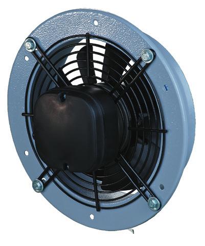
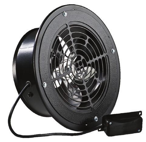
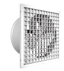
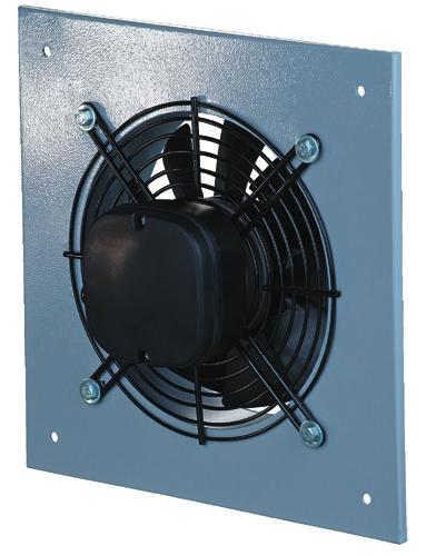
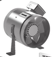
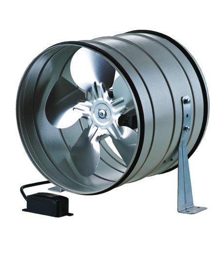
4 FAN DESIGN AXIS-Q / AXIS-QR / AXIS-QA / AXIS-QRA casing cover DELIVERY SET fan 1 item; operation manual. flange flange MODIFICATIONS AND OPTIONS Fig. 1 terminal block impeller AXIS-Q Fan with a square mounting plate AXIS-QR Fan with a round mounting plate FAN DESIGN AXIS-F DELIVERY SET casing terminal block fan 1 item; operation manual. impeller Fig. 2 FAN DESIGN TUBO-M / TUBO-MZ DELIVERY SET fan 1 item; screws and dowels - 4 items; mounting brackets 2 items; operation manual. casing MODIFICATIONS AND OPTIONS Fig. 3 impeller mounting bracket TUBO-M Fan made of polymer coated steel TUBO-MZ Fan made of galvanized steel 4
5 TECHNICAL DATA AXIS-Q / AXIS-QR / AXIS-F Technical data 200 2E 250 2E 250 4E 300 2E Voltage 1~ ~ ~ ~ Frequency [Hz] Power [W] Current [A] Max. air flow [m 3 /h] RPM [min -1 ] Noise level, 3 m [dba] Max. transported air temperature [ C] Ingress Protection Rating 300 4E 350 4E 400 4E 450 4E Voltage 1~ ~ ~ ~ Frequency [Hz] Power [W] Current [A] Max. air flow [m 3 /h] RPM [min -1 ] Noise level, 3 m [dba] Max. transported air temperature [ C] Ingress Protection Rating 500 4E 550 4E 630 4E 630 6E Voltage 1~ ~ ~ ~ Frequency [Hz] Power [W] Current [A] Max. air flow [m 3 /h] RPM [min -1 ] Noise level, 3 m [dba] Max. transported air temperature [ C] Ingress Protection Rating 5
6 D 250 4D 300 2D 300 4D Voltage 3~ 400 3~ 400 3~ 400 3~ 400 Frequency [Hz] Power [W] Current [A] Max. air flow [m 3 /h] RPM [min -1 ] Noise level, 3 m [dba] Max. transported air temperature [ C] Ingress Protection Rating Axis-Q / Axis-QR / Axis-F 350 4D Axis-Q / Axis-QR / Axis-F 400 4D Axis-Q / Axis-QR / Axis-F 450 4D Axis-Q / Axis-QR / Axis-F 500 4D Axis-Q / Axis-QR / Axis-F 550 4D Axis-Q / Axis-QR / Axis-F 630 4D Voltage 3~ 400 3~ 400 3~ 400 3~ 400 3~ 400 3~ 400 Frequency [Hz] Power [W] Current [A] Max. air flow [m 3 /h] RPM [min -1 ] Noise level, 3 m [dba] Max. transported air temperature [ C] Ingress Protection Rating Overall dimensions Ø D Ø d B B1 L Axis-Q 200 2E Axis-Q 250 2E / Axis-Q 250 2D Axis-Q 250 4E / Axis-Q 250 4D Axis-Q 300 2E Axis-Q D Axis-Q 300 4E Axis-Q 300 4D Axis-Q 350 4E / Axis-Q 350 4D Axis-Q 400 4E / Axis-Q 400 4D Axis-Q 450 4E / Axis-Q 450 4D Axis-Q 500 4E / Axis-Q 500 4D Axis-Q 550 4E / Axis-Q 550 4D Axis-Q 630 4E / Axis-Q 630 4D Axis-Q 630 6E Fig. 4 Axis-Q 6
7 Overall dimensions Ø D Ø D1 Ø D2 Ø d L Axis-QR 200 2E Axis-QR 250 2E / Axis-QR 250 2D Axis-QR 250 4E / Axis-QR 250 4D Axis-QR 300 2E Axis-QR 300 2D Axis-QR 300 4E Axis-QR 300 4D Axis-QR 350 4E / Axis-QR 350 4D Axis-QR 400 4E / Axis-QR 400 4D Axis-QR 450 4E / Axis-QR 450 4D Axis-QR 500 4E / Axis-QR 500 4D Axis-QR 550 4E / Axis-QR 550 4D Axis-QR 630 4E / Axis-QR 630 4D Axis-QR 630 6E Fig. 5 Axis-QR Ø D Ø D Ø D Ø d B L Axis-F 200 2E Axis-F 250 2E / Axis-F 250 2D Axis-F 250 4E / Axis-F 250 4D / 3.84 Axis-F 300 2E / Axis-F 300 2D Axis-F 300 4E / Axis-F 300 4D / 5.31 Axis-F 350 4E / Axis-F 350 4D Axis-F 400 4E / Axis-F 400 4D Axis-F 450 4E / Axis-F 450 4D Axis-F 500 4E / Axis-F 500 4D Axis-F 550 4E / Axis-F 550 4D Axis-F 630 4E / Axis-F 630 4D / / / 16.4 Fig. 6 Axis-F 7
8 AXIS-QA / AXIS-QRA / TUBO-MZ / TUBO-F Technical data Tubo-F 200 2E* Tubo-F 250 2E* Tubo-F 250 4E* Tubo-F 300 2E Tubo-F 300 4E* Tubo-F 350 4E Voltage, 50 Hz [V] Power [W] Current [A] Max. air flow [m 3 /h] RPM [min -1 ] Noise level, 3 m [dba] Max. transported air temperature [ C] Ingress Protection Rating IPX4 IPX4 IPX4 IPX4 IPX4 IPX4 * Compliant to the ErP-regulation (EC) 327/2011, the power consumption at optimum efficiency is < 125 W. Axis-QA / Axis-QRA / Tubo-M / Tubo-MZ / Axis-QA G 150 Axis-QA / Axis-QRA / Tubo-M / Tubo-MZ/ Axis-QA G 200 Axis-QA / Axis-QRA / Tubo-M / Tubo-MZ/ Axis-QA G 250 Axis-QA / Axis-QRA / Tubo-M / Tubo-MZ 315 Voltage, 50 Hz [V] Power [W] Current [A] Max. air flow [m 3 /h] RPM [min -1 ] Noise level, 3 m [dba] Max. transported air temperature [ C] Ingress Protection Rating Tubo-M IPX4 Tubo-M IPX4 Tubo-M IPX4 Tubo-M IPX4 Overall dimensions Ø D Ø d B B1 L Axis-QA Axis-QA Axis-QA Axis-QA Axis-QA Fig. 7 8
9 Ø D Ø D1 Ø D2 Ø d L Axis-QRA Axis-QRA Axis-QRA Axis-QRA Axis-QRA Fig. 8 Ø D B L L1 L3 Tubo-M 150 / Tubo-MZ Tubo-M 200 / Tubo-MZ Tubo-M 250 / Tubo-MZ Tubo-M 315 / Tubo-MZ Tubo-M / Tubo-MZ Fig. 9 Ø D B L H L1 Tubo-F 2E Tubo-F 250 2E Tubo-F 250 4E Tubo-F 300 2E Tubo-F 4E Tubo-F 350 4E Tubo-F Fig. 10 Ø D Ø d B B1 L Axis-QA 150 G Axis-QA 200 G Axis-QA 250 G Axis-QA G Fig. 11 Ø D Ø D1 H H1 MD / MDZ 148/ MD / MDZ 198/ MD / MDZ 248/ MD / MDZ reducer for Tubo-M fans The Tubo-M fans are equipped with MD (polymer-coated steel) and MDZ Zn (galvanised steel) reducers for connection to 150 mm, 200 mm and 250 mm air ducts. The reducers are not included in the delivery set and must be ordered separately. Fig. 12 9
10 MOUNTING AND OPERATION GUIDELINES The air motion direction in the system must match the pointer on the fan casing. Install the fan to ensure sufficient and quick access for servicing and repair operations. The fan must be grounded. While mounting protect the fan against water ingress in the following way: 1. Install an outer hood above in case of vertical mounting position, fig. 13. Fig. 13 MOUNTING SEQUENCE AXIS-QA Fig. 15 Fig. 14 AXIS-QR AXIS-Q 10 AXIS-QRA Fig. 16 Fig. *** 17 Fig. 18 Fig. 19 Fig. 20 Fig. 21 Fig. 22 Fig. 23 Fig. 24 Fig. 25 Fig. 26 Fig. 27
11 MOUNTING SEQUENCE AXIS-F MOUNTING SEQUENCE TUBO-M / TUBO-MZ Fig. 28 Fig. 29 Fig. 32 Fig. 33 Fig. 30 Fig. 31 Fig. 34 Fig. 35 Fig. 36 Fig. 37 INSTALLATION AND CONNECTION TO POWER MAINS Connection of the fan to power mains is allowed by a qualified electrician only. The rated electrical parameter are stated on the rating plate. No modifications of internal connections are allowed and will result in void warranty. Connect the fan only to power mains with valid electric standards. The house cabling system must be equipped with an automatic switch at the external input. Connect the fan to power mains through the automatic switch. The contact gap on all poles at least 3 mm. The automatic switch trip current must be in compliance with the fan current consumption, refer Table on pages 5 6. Install the automatic switch to ensure prompt access. AXIS-Q AXIS-QR AXIS-F ~230 V 50 Hz L N PE QF L N X ~4 5 Cut power supply to the fan off by turning the automatic electric switch QF to OFF position (fig. 38). Take steps to prevent activation of the automatic switch. ~230 V 50 Hz L N PE QF L N X Fig 39 ~400 V 50 Hz Single-phase fans L1 L2 L3 PE QF L1 L2 L3 X Fig. 40 Three-phase fans AXIS-QA Fig. 38 The fan wiring diagram is shown in fig Connection sequence of the fan, shown on fig AXIS-QRA TUBO-M / TUBO-MZ AXIS-QA G TUBO-F ~230 V 50 Hz L N QF L N X PE Fig
12 INSTALLATION AND CONNECTION TO POWER MAINS AXIS-Q AXIS-QR Fig. 42 Fig. 43 Fig. 44 Fig. 45 Fig. *** 47 Fig. *** 48 Fig. Abb.49 *** Fig. 51 Fig. 52 Fig. 53 Fig. 55 Fig. 56 AXIS-F Fig. 46 AXIS-QA AXIS-QRA Fig. 50 AXIS-QA G TUBO-M / TUBO-MZ Fig
13 MAINTENANCE Regular technical supervision and maintenance of the fan are required to ensure the product long service life and non-stop operation. Disconnect the fan from power mains prior to any maintenance operations, fig. 57. Do not place the fan in water (fig. 58). Maintenance of the fan is required and means cleaning the fan surfaces from dust and dirt. Maintenance includes regular cleaning, control of the impeller, motor, impeller blades. Mounting sequence of the fan is shown on fig Fig. 57 Fig. 58 Clean the impeller blades with a soft cloth or a brush wetted in a mild soap solution. Avoid liquid splashing on the motor. Clean the impeller blades thoroughly at least once in 6 months. Operation recommendations: 1. Clean the fan regularly from dust, dirt and foreign objects. 2. Check all fastening connections periodically. 3. Control generated noise and vibration. High vibration may indicate the bearing wear, sticking of the dirt particles contained in the transported air, the impeller blades wear, loose connection between the fan and the air duct. 4. Check periodically the fastening connections, impeller for possible blade damages, check connection of the fan to the air duct and coating. AXIS-Q AXIS-QA AXIS-QR AXIS-QRA AXIS-QA G Fig. 59 Fig. 60 Fig. 61 Fig. 62 Fig. 63 Fig. 64 Fig. 65 Fig. 66 AXIS-F TUBO-M / TUBO-MZ TUBO-F Fig. 67 Fig. 68 Fig. 69 Fig
14 ACCEPTANCE CERTIFICATE Axial fans Axis TUBO is recognized as serviceable. The unit complies with the requirements according to the EU norms and directives, to the relevant EU-Low Voltage Equipment Directives, EU-Directives on Electromagnetic Compatibility. We hereby declare that the unit complies with the essential protection requirements of Electromagnetic Council Directive 2004/108/EC, 89/336/EEC and Low Voltage Directive 2006/95/EC, 73/23/EEC and CE-marking Directive 93/68/EEC on the approximation of the laws of the Member States relating to electromagnetic compatibility, which relate to electrical appliances used in set voltage classes. This certificate is issued following test carried out on samples of the product referred to above. Quality Inspector s Stamp Manufacture Date CONNECTION CERTIFICATE Axial fans Axis TUBO is connected to power mains in compliance with the operation manual requirements by the professional: Company: Expert s Full Name Date Signature WARRANTY CARD Axis TUBO SELLER PURCHASE DATE REPRESENTATIVE IN EU BLAUBERG Ventilatoren GmbH Aidenbachstr. 52 D Munich, Germany 14
15 15

16 BL_AXIS_4(8)_EN
INLINE CENTRIFUGAL FAN. Centro-M OPERATION MANUAL
 INLINE CENTRIFUGAL FAN OPERATION MANUAL www.blaubergventilatoren.de CONTENT 3 Introduction 3 General 3 Safety rules 3 Transport and storage requirements 3 Manufacturer's warranty 4 Fan design 4 Delivery
INLINE СENTRIFUGAL FAN BOX BOX-R OPERATION MANUAL
 INLINE СENTRIFUGAL FAN BOX BOX-R OPERATION MANUAL CONTENT 3 Introduction 3 General 3 Safety rules 3 Storage and transportation rules 3 Manufacturer s warranty 4 Fan design 4 Delivery set 5 Technical data
SOUND-INSULATED FAN. Iso-K OPERATION MANUAL. Iso-K_v.1(2)-EN.indd :20:59
-EN.indd :20:59") SOUND-INSULATED FAN OPERATION MANUAL _v.1(2)-en.indd 1 10.08.2015 15:20:59 CONTENT Introduction 3 General 3 Safety rules 3 Transport and storage requirements 3 Manufacturer's warranty 3 Fan design 4 Delivery
SOUND-INSULATED FAN OPERATION MANUAL _v.1(2)-en.indd 1 10.08.2015 15:20:59 CONTENT Introduction 3 General 3 Safety rules 3 Transport and storage requirements 3 Manufacturer's warranty 3 Fan design 4 Delivery
Wind. Service instruction
 Wind Service instruction E BAUBERG Company is happy to offer your attention the window axial Blauberg Wind fan. The solid team of high-qualified professionals with many years of working experience, technological
Turbo. Service Instructions
 Turbo Service Instructions E BAUBERG Company is happy to offer your attention a new highquality inline mixed-flow Blauberg Turbo fan. The solid team of highqualified professionals with many years of working
CENTRIFUGAL FAN IN SCROLL CASING. Helix S-Vent OPERATION MANUAL
 CENTRIFUGAL FAN IN SCROLL CASING Helix S-Vent EN OPERATION MANUAL Helix / S-Vent www.blaubergventilatoren.de CONTENTS CONTENTS 3 Introduction 3 Use 3 Delivery set 4 Technical data 10 Safety requirements
Aero. Service Instructions
 Aero ervice Instructions E BAUBERG Company is happy to offer your attention a new generation product, the BAUBERG Aero fan. The solid team of highqualified professionals with many years of working experience,
SINGLE-ROOM REVERSIBLE UNIT WITH HEAT AND HUMIDITY RECOVERY VENTO V50-1 OPERATION MANUAL
 SINGLE-ROOM REVERSIBLE UNIT WITH HEAT AND HUMIDITY RECOVERY VENTO V50-1 EN OPERATION MANUAL CONTENTS Introduction 3 General 3 Safety rules 3 Transportation and storage rules 3 Manufacturer's warranty 3
Smart Smart IR. Service instruction SALES DATE MANUFACTURED ON (DATE): APPROVAL MARK SOLD. model (check applicable) is recognized as serviceable
: APPROVAL MARK SOLD. model (check applicable) is recognized as serviceable") Smart Smart IR model (check applicable) is recognized as serviceable Service instruction SALES DATE MANUFACTURED ON (DATE): SOLD APPROVAL MARK SMART-EN-04 BLAUBERG Company is happy to offer your attention
Smart Smart IR model (check applicable) is recognized as serviceable Service instruction SALES DATE MANUFACTURED ON (DATE): SOLD APPROVAL MARK SMART-EN-04 BLAUBERG Company is happy to offer your attention
OPERATION MANUAL CENTRIFUGAL INLINE FAN WITH ELECTRONICALLY COMMUTATED MOTOR VKM EC SERIES. F88EN-02.indd :07:11
 OPERATION MANUAL CENTRIFUGAL INLINE FAN WITH ELECTRONICALLY COMMUTATED MOTOR VKM EC SERIES F88EN-02.indd 1 04.09.2015 8:07:11 2 VKM ЕС CONTENT Introduction Use Structural designation key Delivery set Main
HEAT RECOVERY AIR HANDLING UNIT
 HEAT RECOVERY AIR HANDLING UNIT OPERATION MANUAL KOMFORT_L v2(2)_en.indd 1 07.08.2015 15:0:44 CONTENTS Introduction General Safety regulations Transportation and storage regulations Manufacturer's warranty
Calm. Service Instructions
 Calm E ervice Instructions BAUBERG VETIATORE GmbH is happy to offer you a new generation product, the BAUBERG Calm fan. The solid team of high-qualified professionals with many years of working experience,
USER S MANUAL. VCU/VCUN Series CENTRIFUGAL FAN IN SCROLL CASING
 USER S MANUAL VCU/ Series CENTRIFUGAL FAN IN SCROLL CASING 2 CONTENTS Introduction Use Delivery set Designation key Technical data Safety requirements Design and operating logic Mounting and set-up Connection
AXIAL FANS USER S MANUAL
 AXIAL FANS USER S MANUAL WARNING! Disconnect the fan from power supply prior to any connection, servicing and repair operations. Only duly qualified electricians with valid electrical permit for electric
РУКОВОДСТВО USER ПО MANUAL ЭКСПЛУАТАЦИИ CENTRIFUGAL INLINE FANS VKM / VKMZ / VC SERIES
 РУКОВОДСТВО USER ПО MANUAL ЭКСПЛУАТАЦИИ CENTRIFUGAL INLINE FANS / Z / VC SERIES 2 / z / VC CONTENT Use Delivery set Structural designation key Main technical data Safety requirements Fan design Connection
SINGLE ROOM HEAT RECOVERY AIR HANDLING UNIT
 SINGLE ROOM HEAT RECOVERY AIR HANDLING UNIT EN OPERATION MANUAL www.blaubergventilatoren.de CONTENTS 3 Introduction 3 General 3 Safety rules 3 Transportation and storage rules 3 Manufacturer's warranty
CENTRIFUGAL FANS user's manual. model VENTS VK.
 EN CENTRIFUGAL FANS user's manual model VENTS VK www.ventilation-system.com 2013 EN! WARNING! Disconnect the fan from power mains prior to any connection, servicing and repair operations. Mounting and
DUCT COOLERS KWK KFK OPERATION MANUAL. KWK_KFK_v2(4)_EN.indd :35:29
_EN.indd :35:29") DUCT COOLERS KWK KFK EN OPERATION MANUAL KWK_KFK_v2(4)_EN.indd 1 13.06.2016 13:35:29 CONTENTS 3 Introduction 3 General 3 Safety rules 3 Transportation and storage regulations 3 Manufacturer s warranty
DUCT COOLERS KWK KFK EN OPERATION MANUAL KWK_KFK_v2(4)_EN.indd 1 13.06.2016 13:35:29 CONTENTS 3 Introduction 3 General 3 Safety rules 3 Transportation and storage regulations 3 Manufacturer s warranty
SOUND-INSULATED FAN. Iso-B OPERATION MANUAL
 SOUND-INSULATED FAN Iso-B EN OPERATION MANUAL Iso-B www.blaubergventilatoren.de CONTENTS Safety requirements... 3 Introduction... 5 Purpose... 5 Delivery set... 5 Technical data... 6 Design and operating
INTELLIGENT AXIAL FAN user's manual
 ACCEPTANCE CERTIFICATE The fan is duly recognized as serviceable. ifan Approval mark Manufactured on (date) Sold (name and stamp of the trade company) INTELLIGENT AXIAL FAN user's manual model VENTS ifan
USER S MANUAL. Centrifugal inline fan. VKMz 100 Q VKMz 100 VKMz 125 Q VKMz 125. VKMz 250 Q VKMz 250 VKMz 315 Q VKMz 315
 USER S MANUAL VKMz 100 Q VKMz 100 VKMz 125 Q VKMz 125 VKMz 150 VKMz 160 VKMz 200 Q VKMz 200 VKMz 250 Q VKMz 250 VKMz 315 Q VKMz 315 Centrifugal inline fan VKMz CONTENTS Contents... 2 Safety requirements...
USER S MANUAL. VKP Series INLINE FAN
 USER S MANUAL Series INLINE FAN 2 CONTENTS Safety requirements 3 Introduction 5 Use 5 Delivery set 5 Designation key 5 Technical data 5 Design and operating logic 8 Mounting and set-up 8 Connection to
AXIAL FAN User s manual. Quiet-dMEV 100 DC.
 AXIAL FAN User s manual Quiet-dMEV 100 DC www.ventilation-system.com CONTENTS Delivery set... 6 Brief description... 6 Operating guidelines... 6 Designation key... 7 Installation and set-up... 7 Fan options...
Axial intelligent fan USER S MANUAL
 Axial intelligent fan USER S MANUAL CONTENTS Delivery set... 6 Technical data... 6 Installation and set-up... 9 Connection to power mains... 11 Operation guidelines... 11 Unit control... 12 Storage and
INLINE MIXED FLOW FANS IN SOUND INSULATED CASING VENTS TT SILENT M USER MANUAL
 IIE MIED FOW FAS I SOUD ISUATED CASIG VETS TT SIET M USER MAUA www.ventilation-system.com 2013 ! WARIG Disconnect the fan from power mains prior to any connection, servicing and repair operations. Mounting
Centrifugal inline fans
 USER S MANUAL VKM 100 Q VKM 100 VKM 125 Q VKM 125 VKM 150 E VKM 150 VKMS 150 VKM 160 VKMS 160 VKM 200 VKMS 200 VKM 250 E VKM 250 VKM 315 VKMS 315 VKM 355 Q VKM 400 VKM 450 Centrifugal inline fans VKM CONTENTS
INLINE MIXED-FLOW FANS VENTS TT SERIES USER'S MANUAL.
 IIE MIXED-FOW FAS VETS TT SERIES USER'S MAUA www.ventilation-system.com 2011 Read this manual carefully before installation and commissioning of the unit.! READ THE ISTRUCTIOS CAREFUY TO REDUCE THE RISK
AXIAL DOMESTIC FANS. User manual LARUS LIBELLA FENESO CYCNUS CICONUS SIGILA SIGILA MOTION
 AXIAL DOMESTIC FANS User manual LARUS LIBELLA FENESO CYCNUS CICONUS SIGILA SIGILA MOTION SAFETY REQUIREMENTS Disconnect the fan from power mains prior to any connection, servicing and repair operations.
CENTRIFUGAL CEILING EXTRACT FAN
 CENTRIFUGAL CEILING EXTRACT FAN 110 Т/H/IR 110 Light Т/H/IR 150 Т/H/IR 150 Light Т/H/IR EN USER'S MANUAL CONTENTS Contents... 2 Safety requirements... 2 Purpose... 4 Delivery Set... 4 Designation key...
HEAT RECOVERY VENTILATOR
 HEAT RECOVERY VENTILATOR HRV H 00 ERV H 00 HRV H 300 ERV H 300 EN OPERATION MANUAL HRV /ERV H 00(300) www.blaubergventilatoren.de CONTENTS Application... Delivery set...3 Unit designation key...3 Basic
CENTRIFUGAL CEILING EXTRACT FAN
 CENTRIFUGAL CEILING EXTRACT FAN Ceileo 200/250/300 Ceileo 200/250/300 Т/H/IR Ceileo 200/250/300 Light Ceileo 200/250/300 Light Т/H/IR EN USER'S MANUAL CONTENTS Safety requirements... 2 Purpose... 4 Delivery
AXIAL FANS user's manual. model Quiet
 E AXIA FA user's manual model Quiet 0 ! WARIG Disconnect the fan from power mains prior to any connection, servicing and repair operations. Mounting and maintenance are allowed for duly qualified electricians
USER S MANUAL NKP. Duct heater for supply air pre-heating with external control
 USER S MANUAL Duct heater for supply air pre-heating with external control CONTENTS Contents... 2 Safety requirements... 2 Purpose... 4 Delivery set... 4 Designation key... 4 Technical data... 5 Design
USER'S MANUAL PS
 USER'S MANUA 067-0. PS ROOF FANS VENTS VKV \ VKH \ VKV EC \ VKH EC \ VKMK \ VKMKp \ VOK \ VOK SERIES VKV, VKH, VKV EC, VKH EC, VKMK, VKMKp, VOK, VOK CONTENT. Application р.. Delivery set р.. Designation
AIR HANDLING UNIT WITH HEAT RECOVERY
 AIR HANDLING UNIT WITH HEAT RECOVERY Freshbox 100 EN OPERATION MANUAL Freshbox 100 www.blaubergventilatoren.de CONTENTS Safety requirements... 2 Purpose... 4 Delivery set... 4 Designation key... 4 Technical
USER'S MANUAL INLINE CENTRIFUGAL FANS IN SOUND-INSULATED CASING VS, VS EC SERIES
 USER'S MAUA IIE CETRIFUGA FAS I SOUD-ISUATED CASIG VS, VS EC SERIES PURPOSE The inline centrifugal fan VS / VS EC enclosed in a sound-insulated casing with the intake spigot diameter from up to 70 mm,
USER S MANUAL. Heat (Energy) Recovery Ventilator. Vents Frigate HRV 120 S Vents Frigate ERV 120 S
 Recovery Ventilator. Vents Frigate HRV 120 S Vents Frigate ERV 120 S") USER S MANUAL Heat (Energy) Recovery Ventilator Vents Frigate HRV 120 S Vents Frigate ERV 120 S 2 Frigate HRV(ERV) 120 S CONTENT Introduction... 3 Application... 3 Delivery set... 3 Unit designation key...
USER S MANUAL Heat (Energy) Recovery Ventilator Vents Frigate HRV 120 S Vents Frigate ERV 120 S 2 Frigate HRV(ERV) 120 S CONTENT Introduction... 3 Application... 3 Delivery set... 3 Unit designation key...
Air handling unit. BlauAir RH USER S MANUAL
 Air handling unit EN USER S MANUAL CONTENTS Safety requirements... 2 Purpose... 4 Delivery set... 4 Designation key... 4 Technical data... 5 Unit design and operation logic... 7 Installation and set-up...
USER S MANUAL DN-2. Drain pump
 USER S MANUAL DN-2 CONTENTS Safety requirements... 2 Purpose... 3 Delivery set... 3 Technical data... 3 Design... 4 Installation and set-up... 5 Connection to power mains... 8 Storage and transportation
USER MANUAL. Air handling unit with heat recovery. VUT 300 EVK mini EC VUT 300 EV mini EC VUT 301 EVK mini EC VUT 301 EV mini EC
 USER MANUAL Air handling unit with heat recovery VUT 300 EVK mini EC VUT 300 EV mini EC VUT 301 EVK mini EC VUT 301 EV mini EC 2 CONTENTS Introduction Use Delivery set Structural designation key Technical
HEAT RECOVERY AND HEAT AND HUMIDITY RECOVERY AIR HANDLING UNIT
 HEAT RECOVERY AND HEAT AND HUMIDITY RECOVERY AIR HANDLING UNIT S S11 Series SB S11 Series SB -E S11 Series SB -E S11 Series EN OPERATION MANUAL CONTENTS Safety requirements... 2 Purpose... 4 Delivery set...
USER S MANUAL. Heat Recovery Ventilator. Vents Brig HRV 200 Vents Brig HRV 300
 USER S MANUAL Heat Recovery Ventilator Vents Brig HRV 200 Vents Brig HRV 300 2 Brig HRV 200 (300) CONTENT Introduction... 3 Application... 3 Delivery set... 3 Unit designation key... 4 Basic unit dimensions...
HEAT RECOVERY AIR HANDLING UNITS KOMFORT EC S S11/S15 KOMFORT EC SB S11/S15
 HEAT RECOVERY AIR HANDLING UNITS KOMFORT EC S S11/S15 KOMFORT EC SB S11/S15 EN OPERATION MANUAL KOMFORT EC S/SB www.blaubergventilatoren.de CONTENTS 3 Introduction 3 General 3 Safety regulations 3 Transportation
USER'S MANUAL. Single-room reversible energy regeneration ventilator. TwinFresh R-50 TwinFresh RA-50 TwinFresh R-50-2 TwinFresh RA-50-2
 USER'S MANUAL TwinFresh R-50 TwinFresh RA-50 TwinFresh R-50-2 TwinFresh RA-50-2 TwinFresh S-60 TwinFresh SA-60 TwinFresh S-60-2 TwinFresh SA-60-2 TwinFresh S-50 TwinFresh SA-50 TwinFresh S-50-2 TwinFresh
HEAT RECOVERY AIR HANDLING UNITS
 HEAT RECOVERY AIR HANDLING UNITS KOMFORT EC DB S11 KOMFORT EC DB S15 EN OPERATION MANUAL KOMFORT_EC_DB_S11(15)_v2(2-4)_ENG.indd 1 06.08.2015 14:30:31 CONTENTS 3 Introduction 3 General 3 Safety regulations
USER S MANUAL VUT 160 P2B EC A14 VUT 160 PB EC A14 VUT 350 P2B EC A14 VUT 350 PB EC A14 HEAT RECOVERY AIR HANDLING UNIT
 USER S MANUAL VUT 160 P2B EC A14 VUT 160 PB EC A14 VUT 350 P2B EC A14 VUT 350 PB EC A14 HEAT RECOVERY AIR HANDLING UNIT 2 CONTENTS. Safety requirements... 3 Introduction.........................................................
Turbo Inline Fan, White - Non Illuminated Art no.33500
 Quality Bathroom Products Turbo Inline Fan, White - Non Illuminated Art no.33500 Turbo Inline Fan, White - Cool White LED Art no.300 Turbo Inline Fan, White - Warm White LED Art no.34000 Turbo Inline Fan,
Issue5 07/13 USERS MANUAL IN-LINE MIXED FLOW
 90411215-Issue5 07/13 USERS MANUAL IN-LINE MIXED FLOW DESTINATION The in-line mixed flow fans with channels' diameters ranging from 100 to 150 mm are designed for installation in the ventilating systems
White - Non Illuminated Art no White - Cool White LED Art no.32600
 Cyclone Inline Fans White - Non Illuminated Art no.33300 White - Cool White LED Art no.32600 White - Warm White LED Art no.33800 Chrome - Non Illuminated Art no.33400 Chrome - Cool White LED Art no.32700
USER S MANUAL VUT V(B) EC А14 VUE V(B) EC А14. Heat/heat and humidity recovery air handling unit
 EC А14 VUE V(B) EC А14. Heat/heat and humidity recovery air handling unit") USER S MANUAL VUT V(B) EC А14 VUE V(B) EC А14 Heat/heat and humidity recovery air handling unit CONTENTS Safety requirements... 2 Purpose... 4 Delivery set... 4 Designation key... 4 Technical data... 5
USER S MANUAL VUT V(B) EC А14 VUE V(B) EC А14 Heat/heat and humidity recovery air handling unit CONTENTS Safety requirements... 2 Purpose... 4 Delivery set... 4 Designation key... 4 Technical data... 5
USER S MANUAL AiR duct heater with integrated temperature control UNit or A control UNit
 USER S MANUAL Air duct heater with integrated temperature control unit or a control unit 2 CONTENTS Safety requirements 3 Introduction 5 Use 5 Delivery set 5 Designation key 5 Main technical parameters
VUT 350 H VUT 500 H VUT 530 H VUT 600 H VUT 1000 H VUT 2000 H HEAT RECOVERY AIR HANDLING UNIT
 РУКОВОДСТВО USER S MANUAL ПОльзователя VUT 350 H VUT 500 H VUT 530 H VUT 600 H VUT 1000 H VUT 2000 H HEAT RECOVERY AIR HANDLING UNIT 2 CONTENTS Safety requirements 3 Introduction 5 Use 5 Delivery set 5
Installation manual Mini Comfort 50 S/L 07/ V EN
 Installation manual Mini Comfort 50 S/L 07/2015 - V 1.1 - EN www.veneco-ventilation.be Veneco ventilation by Elek Trends Productions nv Blauwfazantjesstraat 4 B - 7700 Moeskroen Tel. +32 (0)56 48 15 90
KKKKKKKCOOKER HOOD INSTRUCTION MANUAL
 KKKKKKKCOOKER HOOD INSTRUCTION MANUAL Read this manual carefully before operation Pictures in this manual are for reference only, the product in kind prevail. E60MEW2M19 Contents 01 02 03 04 05 06 07 08
FRESHBOX 100. Single-room heat recovery unit. Air capacity up to 100 m³/h Heat recovery efficiency up to 96 %
 FRESHBOX 100 Single-room heat recovery unit Air capacity up to 100 m³/h Heat recovery efficiency up to 96 % FRESHBOX 100 CONTENTS FRESHBOX 100 FEATURES 3 DESIGN 4 OPERATING PRINCIPLE 6 CONTROL 6 APPLICATION
CANOPY RANGEHOOD. instruction manual V3FC60SS & V3FC90SS 12 MONTH WARRANTY
 CANOPY RANGEHOOD instruction manual V3FC60SS & V3FC90SS 12 MONTH WARRANTY Contents Guide to the Appliance 2 Caring for the Environment 3 Safety Information and Warnings 4 Installation Instructions 6 Operation
ISCG90SS _03 ISCG90SS
 ISCG90SS 60900355_03 ISCG90SS GB IE [01] x 1 [02] x 1 [03] x 1 [04] x 8 [05] x 1 [06] x 4 [07] x 1 [08] x 1 [09] x 1 [10] x 4 [11] x 4 [12] x 1 [13] x 4 (6x70mm) [14] x 8 (6.3x17x2mm) 1 : 1 [15] x 4 (3.9x18mm)
IN-LINE CENTRIFUGAL FAN VENTS VKP PS 125. User`s manual.
 IN-LINE CENTRIFUGAL FAN VENTS VKP PS 125 EN User`s manual www.vents-us.com EN READ AND SAVE THESE INSTRUCTIONS WARNING! TO REDUCE THE RISK OF FIRE, ELECTRIC SHOCK AND PERSONAL INJURY, READ AND UNDERSTAND
G Installation manual Solitude - dmev unit
 G G Installation manual Solitude - dmev unit Read this manual carefully before using the product and keep it in a safe place for reference. This product was constructed up to standard and in compliance
INSTALLATION AND USER S MANUAL COOKER HOOD RS-600/A-S
 INSTALLATION AND USER S MANUAL COOKER HOOD RS-600/A-S RS-600 (CHS60SS)-GB-05.indd 1 6/8/2010 9:30:59 AM TABLE OF CONTENTS 1. Introduction 2 2. Safety precaution 2 3. Intended use 3 4. Parts supplied 3
Installation and Maintenance Novax Smoke Exhaust Fan Type ACN Smoke
 918149-0 GB Installation and Maintenance Novax Smoke Exhaust Fan Type ACN Smoke 1. Application 2. Handling 2.1 Marking 2.2 Weight 2.3 Transport 3. Storage 4. Installation 4.1 Prior to attachment 4.2 Attachment
OSC... INSTRUCTION MANUAL - KITCHEN EXTRACTOR HOOD
 OSC... INSTRUCTION MANUAL - KITCHEN EXTRACTOR HOOD EN min 450mm Electrical cookers min 650mm Gas cookers min 650mm Gas cookers 1a 1b 1c 2a 2b ELECTRICAL / GAS - 650mm 3a 3b 2 2 x 8 3c 3d 3e 3 0 1 2 3 L
USER MANUAL. Frigate HRV 120 SR Frigate ERV 120 SR. Heat (energy) recovery ventilation unit
 recovery ventilation unit") USER MANUAL Frigate HRV 120 SR Frigate ERV 120 SR Heat (energy) recovery ventilation unit 2 CONTENTS Safety requirements... 3 Introduction... 5 Use... 5 Included in the box... 5 Designation key... 5 Technical
USER MANUAL Frigate HRV 120 SR Frigate ERV 120 SR Heat (energy) recovery ventilation unit 2 CONTENTS Safety requirements... 3 Introduction... 5 Use... 5 Included in the box... 5 Designation key... 5 Technical
FRESHBOX 100. Single-room heat recovery unit. Air flow up to 59 CFM Heat recovery efficiency up to 96 %
 Single-room heat recovery unit Air flow up to 59 CFM Heat recovery efficiency up to 96 % 2018 SINGLE-ROOM HEAT RECOVERY UNITS Features Efficient solution for supply and exhaust ventilation of enclosed
Cooker Hood User Manual
 Cooker Hood User Manual HCB93042X EN 01M-8850803200-0116-02 Please read this manual first! Dear Customers! Thank you for preferring a Beko product. We hope that you get the best results from your product
USER'S MANUAL. Micra 150 HEAT RECOVERY UNIT
 USER'S MANUAL Micra 150 HEAT RECOVERY UNIT 2 Micra 150 CONTENTS Introduction Use Included in the Box Designation Key Example Technical data Safety requirements DESIGN AND OPERATION Mounting and Installation
Box60/ 70/ 90. Box60_70_90 v8
 Box60/ 70/ 90 Box60_70_90 v8 GB IE [01] x 1 [02] x 2 [03] x 1 [04] x 2 [05] 60cm, 70cm x 2 90cm x 3 [06] x 1 [07] x 1 1 : 1 [09] x 6 (3.9 x 32mm) [08] x 6 [10] x 4 (3.4 x 10mm) Box60/ 70/ 90 GB IE Cooker
IN 900 BIC UK INSTRUCTION MANUAL - KITCHEN EXTRACTOR HOOD
 IN 900 BIC UK INSTRUCTION MANUAL - KITCHEN EXTRACTOR HOOD EN Before using the appliance, please carefully read this manual! 2 3 min 450mm Electrical cookers min 650mm Gas cookers min 650mm Gas cookers
Instructions for use PHPC 6.4F AM X
 EN English, 7 Instructions for use PHPC 6.4F AM X 2 3 4 5 6 English GENERAL SAFETY Before any cleaning or maintenance operation, disconnect hood from the mains by removing the plug or disconnecting the
Trumatic E. Trumatic E 2400 (Australia) Operating instructions Page 4 Installation instructions Page 7. To be kept in the vehicle!
 Operating instructions Page 4 Installation instructions Page 7. To be kept in the vehicle!") Trumatic E 7 7 2 9 9 4 Trumatic E 2400 (Australia) Operating instructions Page 4 Installation instructions Page 7 To be kept in the vehicle! Trumatic E 2400 (Australia) Table of contents Installation example...
Trumatic E 7 7 2 9 9 4 Trumatic E 2400 (Australia) Operating instructions Page 4 Installation instructions Page 7 To be kept in the vehicle! Trumatic E 2400 (Australia) Table of contents Installation example...
Safety and Instruction Manual
 T14002 Safety and Instruction Manual PLEASE READ CAREFULLY 30cm Ceramic Coated Electric Sauté Pan T14002 30cm Ceramic Coated Electric Sauté Pan TECHNICAL DATA Description: Model: Rated Voltage: Input power:
USER S MANUAL BUCKET FAN SERIES BUCKET FAN WHISPER SERIES
 USER S MANUAL BUCKET FAN SERIES BUCKET FAN WHISPER SERIES Bucket Fan 420 Bucket Fan 1055 Bucket Fan 1460 420 1055 1460 2 Bucket Fan CONTENT INTRODUCTION 3 USE 3 WHAT S INCLUDED IN THE BOX 3 DESIGNATION
CAN60 / CAN60SV _01 CAN60_CAN60SV. WARNING: Read the instructions before using the appliance.
 CAN60 / CAN60SV 60901870_01 CAN60_CAN60SV GB IE WARNING: Read the instructions before using the appliance. [01] x 1 [02] x 1 [03] x 2 [04] x 1 1 : 1 [05] x 4 (4x 32mm) [6] x 2 (3x 12mm) Cooker hood GB
General safety precautions English
 English 1 1 1.1 About the documentation The original documentation is written in English. All other languages are translations. The precautions described in this document cover very important topics, follow
Operating instructions
 Operating instructions (Translation of the original operating instructions) Type TEKA FILTERCUBE-MV TEKA Absaug- und Entsorgungstechnologie GmbH Industriestraße 13 D-46342 Velen Postfach 1137 D-46334 Velen
UNDERMOUNT RANGEHOOD. instruction manual VPP52S & VPP90S 12 MONTH WARRANTY
 UNDERMOUNT RANGEHOOD instruction manual VPP52S & VPP90S 12 MONTH WARRANTY Contents Guide to the Appliance 2 Caring for the Environment 3 Safety Information and Warnings 4 Installation Instructions 6 Operation
User s Manual WALL MOUNT SERIES TABLE OF CONTENTS RA7730SS/RA77B30SS RA7736SS/RA77B36SS RA7742SS/RA77B42SS RA7748SS/RA77B48SS.
 TABLE OF CONTENTS 1 Table of Contents www.windsterhood.com Safety Information... 2 3 WALL MOUNT SERIES User s Manual RA7730SS/RA77B30SS RA7736SS/RA77B36SS RA7742SS/RA77B42SS RA7748SS/RA77B48SS NOTE: PLEASE
General safety precautions English
 English 1 1 1.1 About the documentation The original documentation is written in English. All other languages are translations. The precautions described in this document cover very important topics, follow
HG 675 CX 60 HG 675 CN 60 HG 675 CW 60
 HG 675 X 60 HG 675 CX 60 HG 675 CN 60 HG 675 CW 60 1 2 1. : 93/68: 90/396: 2006/95/CE: 2004/108/CE: - 1935/2004:. 2002/95/CE: RoHS 2.,.,,,,...,. (,..)..,,.,. ( ),,, ;,,.,.....,.,,,,,,...,. (..),,.,..,.,,,,
User s Manual RA-3030SS RA-3036SS. NOTE: This unit was designed for indoor residential use and DUCTED operation only.
 www.windsterhood.com User s Manual UNDER CABINET SERIES RA-3030SS RA-3036SS NOTE: This unit was designed for indoor residential use and DUCTED operation only. DO NOT USE OVER A WOOD GRILL OR MOUNT OUTDOOR
ACN SMOKE INSTALLATION AND MAINTENANCE
 NovAx ACN SMOKE INSTALLATION AND MAINTENANCE 918149-0 English 918149-0 GB Installation and maintenance NovAx smoke exhaust fan type ACN smoke 1. Application 2. Handling 2.1 Marking 2.2 Weight 2.3 Transport
BIG BEAR VORTEX FAN MODEL #BB-2
 OWNER S MANUAL BIG BEAR VORTEX FAN MODEL #BB-2 INTRODUCTION OPERATION SAFETY SERVICE WARRANTY CONTACT SPECIFICATIONS TROUBLESHOOTING PLEASE READ AND SAVE THESE INSTRUCTIONS MODEL #BB-2 YOUR NEW BIG BEAR
User s Manual WS-69TB30 / WS-69TB36 (22 ) WS-69TB42 / WS-69TB48 (22 ) WS-69TS30 / WS-69TS36 (18 ) WS-69TS42 / WS-69TS48 (18 )
 WS-69TB42 / WS-69TB48 (22 ) WS-69TS30 / WS-69TS36 (18 ) WS-69TS42 / WS-69TS48 (18 )") www.windsterhood.com User s Manual LINER SERIES WS-69TB30 / WS-69TB36 (22 ) WS-69TB42 / WS-69TB48 (22 ) WS-69TS30 / WS-69TS36 (18 ) WS-69TS42 / WS-69TS48 (18 ) NOTE: PLEASE INSPECT HOOD IMMEDIATELY UPON
www.windsterhood.com User s Manual LINER SERIES WS-69TB30 / WS-69TB36 (22 ) WS-69TB42 / WS-69TB48 (22 ) WS-69TS30 / WS-69TS36 (18 ) WS-69TS42 / WS-69TS48 (18 ) NOTE: PLEASE INSPECT HOOD IMMEDIATELY UPON
HEATING AND COOLING DEVICE AGC
 GDYNIA HEATING AND COOLING DEVICE - AGC 2013 1/8 HEATING AND COOLING DEVICE AGC SERVICE phone.: (+48 58) 783 99 50/51 Fax: (+48 58) 783 98 88 mobile: (+48) 510 098 081 E-mail: serwis@klimor.pl GDYNIA,
User s Manual WS-63TB36SS WS-63TB42SS NOTE: PLEASE INSPECT HOOD IMMEDIATELY UPON RECEIVING. CLAIM OF DAMAGE AFTER 7 DAYS OF DELIVERY WILL BE DENIED.
 www.windsterhood.com User s Manual WS-63TB36SS WS-63TB42SS ISLAND SERIES NOTE: PLEASE INSPECT HOOD IMMEDIATELY UPON RECEIVING. CLAIM OF DAMAGE AFTER 7 DAYS OF DELIVERY WILL BE DENIED. This unit is designed
TTV 4500 / TTV 4500 HP / TTV 7000
 TTV 4500 / TTV 4500 HP / TTV 7000 EN OPERATING MANUAL AXIAL FAN TRT-BA-TTV4500-4500HP-7000-TC-003-EN Table of contents The current version of the operating manual can be found at: Notes regarding the operating
100cm Chimney Hood GB IE
 100cm Chimney Hood GB IE [01] x 1 [02] x 2 [03] x 2 [04] x 2 [05] x 3 [06] x 1 [07] x 1 1 : 1 [09] x 8 (3.9 x 32mm) [08] x 8 [10] x 4 (4 x 12mm) 100cm Chimney Hood GB IE Cooker Hood 04 FR Hotte Aspirante
SMHA Hatch High temperature fan HT-fan Installation and Maintenance
 High temperature fan HT-fan Installation and Maintenance 22.8.2012 Contents 1. Important information 2. Safety notes 3. Technical description 4. Transport 5. Mounting instructions 6. Commissioning 7. Maintenance
AP-EH500-L/RQA9837. Installation Guide
 AP-EH500-L/RQA9837 Duct Mounted Burst Fire Heater The EMC Directive 2004/108/EC The Low Voltage directive 2006/95/EC 1.0 Duct Mounted Burst Fire Heater This Burst Fire Heater should only be used as a supplementary
Glue Gun 25W TTB580HTL. Barcode: WARNING: Read the instructions before using the product!
 Glue Gun 25W Original Instructions - MNL_TTB580HTL_V1_140110 TTB580HTL Barcode: 5052931292172 WARNING: Read the instructions before using the product! Congratulations on your purchase of a power tool from
VH60SS 60CM VISOR HOOD STAINLESS STEEL
 VH60SS 60CM VISOR HOOD STAINLESS STEEL INSTRUCTION MANUAL Thank you for purchasing our product. We hope you enjoy using the many features and benefits it provides. Before using this product please study
Table of Contents. Safety Information Content Checklist Measurements Preparation Installation
 TABLE OF CONTENTS 1 Table of Contents Safety Information... 2 3 Content Checklist... 4 Measurements... 5 Preparation... 6 Installation... 7 8 Installation Diagram... 9 Operation & Features... 10 Cleaning
User s Manual WS-62N30SS WS-62N36SS NOTE: PLEASE INSPECT HOOD IMMEDIATELY UPON RECEIVING. CLAIM OF DAMAGE AFTER 7 DAYS OF DELIVERY WILL BE DENIED.
 WALL MOUNT SERIES www.windsterhood.com User s Manual WS-62N30SS WS-62N36SS NOTE: PLEASE INSPECT HOOD IMMEDIATELY UPON RECEIVING. CLAIM OF DAMAGE AFTER 7 DAYS OF DELIVERY WILL BE DENIED. This unit is designed
Operating Manual. VIENNA Hot Display
 Operating Manual VIENNA Hot Display Operating and Maintenance instructions Please read this manual carefully before you start to operate your heated display case. Following these instructions helps you
OPERATION AND MONTAGE MANUAL ROOF FANS
 NO RFEC/U/2017-1 (EN) (valid since 18.08.2017) ROOF FANS RF/EC...-... / RFV/EC...-... Venture Industries Sp. z o.o. is not responsible for any damage caused by improper use of the fan and reserves the
KOMFORT EC S5B KOMFORT EC D5B KOMFORT EC S. Heat and Energy Recovery Ventilators
 KOMFORT EC S5B KOMFORT EC D5B KOMFORT EC S Heat and Energy Recovery Ventilators 2018 AIR HANDLING UNITS 2 CONTENT KOMFORT EC S5B270(-E) 4 KOMFORT EC D5B1(-E) 8 KOMFORT EC S(B)(-E) 12 AIR HANDLING UNITS
IDE 20 / IDE 30 / IDE 50 IDE 60 / IDE 80
 IDE 20 / IDE 30 / IDE 50 IDE 60 / IDE 80 EN OPERATING MANUAL OIL HEATER TRT-BA-IDE20-30-50-60-80-TC-001-EN Table of contents Information on the use of this manual... 1 Scope of delivery... 1 General safety...
Lucci Designer Hi Flow Exhaust Fan
 USE AND CARE INSTRUCTION INSTALLATION INSTRUCTION Lucci Designer Hi Flow Exhaust Fan SKU# 200265&200267 MXSQ8PW(200mm) SKU# 200266&200268 MXSQ10PW(250mm) Dear Customers, Thank you for selecting a LUCCI
User s Manual WS-4830SS WS-4836SS NOTE: PLEASE INSPECT HOOD IMMEDIATELY UPON RECEIVING. CLAIM OF DAMAGE AFTER 7 DAYS OF DELIVERY WILL BE DENIED.
 www.windsterhood.com User s Manual UNDER CABINET SERIES WS-4830SS WS-4836SS NOTE: PLEASE INSPECT HOOD IMMEDIATELY UPON RECEIVING. CLAIM OF DAMAGE AFTER 7 DAYS OF DELIVERY WILL BE DENIED. This unit is designed
USER S OPERATION MANUAL HL-RD 2000 E EC HL-RD 3000 E ЕС
 USER S OPERATION MANUAL HL-RD 2000 E EC HL-RD 3000 E ЕС Air handling unit with heat recovery 2 CONTENT Introduction Use Delivery set Structural designation key Technical data Safety precautions Structure