Respect OC Installation manual
|
|
|
- Clyde Lester
- 5 years ago
- Views:
Transcription

1 Respect OC ENG Installation manual ENG


2 A A A < < < <


3 B C A B A < < < <


4 < < < <

5 A B < < < <


6 L A A 4.1 A A 4.2 A A 4.3 5<<<<
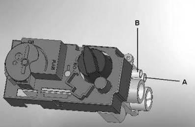
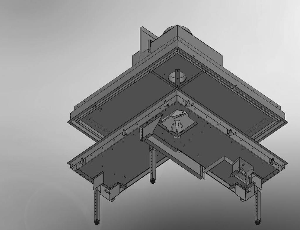
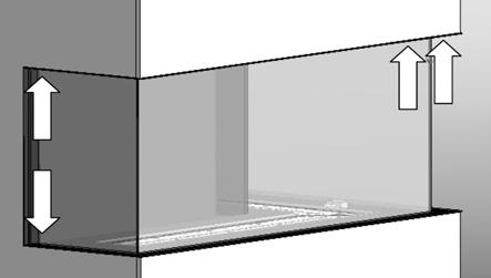
7 1 Introduction The appliance can only be installed by a competent person in accordance with the Gas Safety. We urgently advise you to read this installation manual properly. This appliance complies with the guidelines for European gas appliances (Gas Appliances Directive) and bears the CE mark. 2 Safety instructions. The appliance should be placed, connected and annually checked in accordance with these installation instructions and valid national and local Gas Safety (Installation and Use) Regulations. 6 < < < < Check whether the data on the registration plate are in agreement with the local type of domestic gas and pressure. The fitter is not permitted to change these adjustments or the construction of the appliance! Do not place any additional imitation logs or glowing coals on the burner or in the combustion chamber. The appliance has been designed for ambience and heating purposes. This means that all surfaces of the appliance, including the glass, can become very hot (hotter than 100 C). An exception to this are the bottom of the appliance and the controls. Do not place any inflammable materials within a of 0.5 m. of the radiation of the appliance and ventilation grills. Due to natural air circulation of the appliance, moisture and volatile components from paint, building materials, floor coverings etc. that haven t yet set, can be drawn through the convection system and can be deposited on cold surfaces as soot. That is why you should not use the appliance shortly after a renovation. The first time the appliance is switched on, Let the fire run on maximum setting for several hours so that the lacquer coating will have an opportunity to set and possible vapours released can be safely removed by ventilation. We advise you to be outside the room as much as possible during this process! Please note that: all transport packaging should be removed. children or pets should not be present in the room. 3 Installation requirements 3.1 The fire The appliance must be built into an existing or a newly to be constructed false chimney breast. In appliances with flexible gas pipes, the gas control valve is mounted to the right side of the fire for safe transport. Unscrew it and mount it at a distance of max. 30 cm behind the access door. The receiver which has been attached in a transport holder (see fig. 1.3 A) to the side of control valve bracket, can now be slid onto the top of the control valve bracket. The transport holder can be removed now. 3.2 False Chimney breast The false chimney breast must be constructed of an non-combustible material. Always ventilate the space above the appliance by means of the grills or a comparable alternative with a minimum air supply of 200 cm². For the finish, use special stucco (min. 100 C resistant) or glass fibre wallpaper to prevent discoloration or cracks etc. Recommended drying time: for plaster is a minimum of 24 hours per mm of coat applied. The false chimney breast and its construction may not rest on the appliance 3.3 Requirements flue system and outlets You should always make use of the materials prescribed by Faber Only by using these materials can Faber guarantee a proper functioning. The outside of the concentric flue material can reach a temperature of Approx. 150 C. Make sure of proper isolation and protection in case of
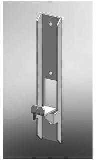
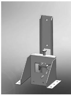
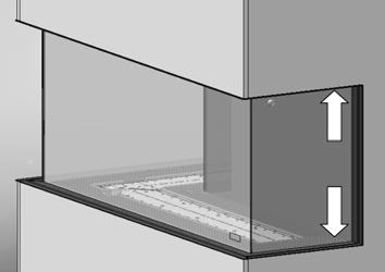
8 transit through combustible wall or ceiling constructions. And observe sufficient distance. Make sure that the concentric flue materials are bracketed every 2 metres when they have an extended length, so that the weight of the flue material is not resting on the appliance itself. You may never start with a cut-down concentric pipe directly on to the appliance. Prepare the gas connection to the gas control valve. 4.4 Moving the appliance If necessary the upper parts of the appliance can be taken of, this gives a minimum dimension of the appliance (780mm), then the appliance can be transported on the back side (see fig. 2.1) It is only allowed to remove the transport plate after the appliance is fixed on the wall(see fig.2.5) 3.4 terminals The flue outlet can end on an external wall or a roof. Check whether the outlet desired by you complies with local requirements concerning good function and ventilation systems. For a proper functioning the terminal should be at least 0.5 m. away from: Corners of the building. Roof overhangs and balconies. Eaves (with the exception of the roof ridge). 4 Preparation and Installation instructions 4.1 Gas connection The gas connection must comply with locally valid standards. We advise Pipe work from the meter to the appliance must be of adequate size., with near the appliance a gas isolater tap that should always be accessible. Place the gas connection in such a way that this is easily accessible, and that before service, the burner unit can be disconnected at all times. 4.2 Electric connection If an adapter is used for the power supply, then a wall socket 230VAC 50Hz must be mounted in the close neighbourhood of the hearth. 4.3 Preparation of the appliance Remove the packaging of the appliance. Make sure the gas pipes underneath the appliance are not damaged. Clear a safe space to store the frame and the glass. Remove the frame, (if necessary) and the glass and take the separately wrapped parts out of the appliance 7 < < < < 4.5 Placing the appliance Take the installation requirements into account (See chapter 3) Correct Levelling of the appliance is very important, otherwise it is possible that the glass plates not match. The unit should always be fixed on a wall, by use of the supplied mounting and fixation brackets (See fig. 2.1 A up to 2.4 ) Standing on the floor Place the appliance into the proper position and if necessary, adjust the height with the adjustable legs. Adjusting the height and levelling the appliance with a spirit level. Rough height adjustment: with the extending legs, or the long additional legs. Accurate: with the rotating adjustable legs. Use the fixation brackets to fix the unit on the wall,(see fig 2.1 A up to 2.4) Remove now the transport plate (See fig. 2.5) Suspended from the wall check the strength of the wall, the Respect weighs approximate, 150 kilos Determine where the unit will be fitted and install the mounting brackets on the wall (See fig.2.2) Now the appliance can hang on these brackets. Level the unit with the adjustable screws in the mounting brackets (See fig. 2.3) Use the fixation brackets to fix the unit on the wall (See fig. 2.4 ) Check if the appliance is aligned and square. Now you can remove the transport plate. See fig. 2.5)
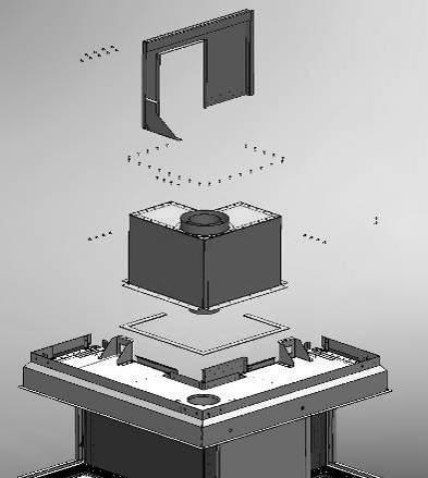
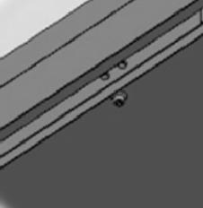
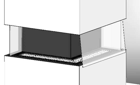
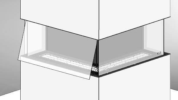
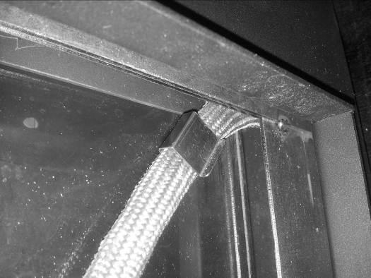
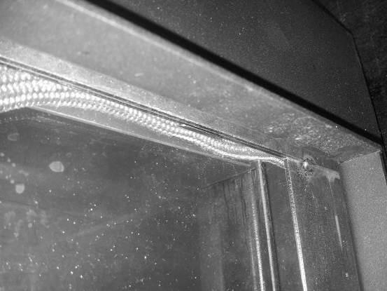
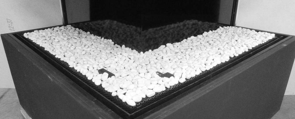
9 Before proceeding with the installation of the fire Install the side and front glass of the fire to check the squareness (See chapter 6) With a correct squareness of the unit, all glass panel will match correctly to each other Note: remove all glass panels after this check and proceed the installation work. 4.6 Mounting the flue materials. In case of a wall or roof terminal, the hole must be at least 5 mm bigger than the diameter of the flue material. Horizontal parts must be installed at a (3 degree) slope up away the appliance. Build up the system from the appliance. If this is not possible, you should make use of a adjustable pipe For fitting the system a ½ metre cut-down pipe should be used. Make sure the inner pipe is always 2 cm longer than the outer pipe. Wall and roof terminal are also shortened. These parts must be secured with a self-tapping screw. Do not insulate but ventilate build-in flue material (approx.100cm2) 4.7 Building a chimney breast. Before constructing the chimney breast we advise you to perform a function test with the appliance as described in chapter 7 checking the installation 4.8 Chimney breast Construct the chimney breast from non-combustible material in combination with metal profiles or of brickwork / aerated concrete bricks. Take the grills and the service panel into account. ( see fig. 1.1 and 1.2). Place a protective shield made of non-combustible material above the grills (see fig 1.1 A). Always use a lintel if the chimney breast is constructed of brickwork. These should not rest onto the buildin frame. The chimney construction may not resting on the build-in frame 5 Placing the decorative material It is not allowed to add different or more materials to the combustion chamber. Always keep the pilot burner and the second thermocouple free from decorative material! (See fig. 4.1 A up to 4.3 A) Do not toss all the decorative material onto the burner all at once, it can be obstructed by dust particles. 5.1 Imitation logs Place a number of the chips onto the burner and on the cover plate Place the imitation logs according to instructions. (see fig. 4.1 or imitation logs instruction card supplied) Divide the remainder of the chips over the burner and the cover plate. Avoid a thick layer onto the burner, this has a negative effect on the fire image. Ignite the pilot and main burner according to the instructions in the user s manual. Assess whether the flame division is correct. If necessary, move the chips until there is a proper division of flames. Place the glass and check the fire image. 5.2 Pebbles / Grey stone Place the pebbles over the burner and the bottom. Spread the pebbles evenly to a double layer. The surface of the pebbles may be very slightly elevated from the burner (see fig.4.2 and 4.3) Place the glass and check the flame picture into the appliance 6 Installation front and side glass Take all glass part out the packing and use the suction discs for placing the glass, the side glass need to be install first Note: before placing the glass remove all fingerprints on the glass, these will be burned into it once the appliance is used. 6.1 Placing side glass Slide the glass between the groove and built-in frame (See fig.3.1) (Next steps all in one move) keep the glass tilted slightly to the side (See fig.3.2). 8 < < < <
10 Now slide the glass up into the upper groove and then place the glass in the bottom groove If the inlet pressure is too high you are not permitted to connect the appliance. 6.2 Placing the front glass Note: first install the right side part slide the glass in the upper groove and then let it slide in to the bottom groove (see fig.3.3) Place the left-hand glass in the same way (see fig.3.4) 6.3 Place the sealing cord in the groove Place the sealing cord and start in the righthand corner, push the sealing cord in the clips on each indicated spot between the glass and groove (see fig.3.5 and 3.6) Place the cover trims A on the side and B on the bottom.(see fig.3.7 ) For dismounting the glass: repeat the process in reverse order. 7 Checking the installation. 7.1 Checking the ignition of the pilot burner, main burner. Start the pilot and main burner according to the instructions in the user s manual. Check whether the pilot light is properly positioned above the main burner and is not covered by chips, an imitation log or pebbles. Check the ignition of the main burner at full mark or low mark. (the ignition should take place quickly and easily). 7.2 Checking for gas leakage. Check all connections and joins for possible gas leaks by means of a gas leak detector or spray 7.3 Checking the burner pressure and the pre-pressure Measuring the inlet-pressure: Turn off the gas control tap. Open the pressure gauge nipple B (see figure 1.4) a few turns and connect a pressure gauge hose to the gas control valve. Carry out this measurement when the appliance is on at full gas mark and when it is on the pilot light. Measuring the burner pressure: Only perform this measurement if the inlet-pressure is correct. Open the pressure gauge nipple A (see fig. 1.4) a few turns and connect a pressure gauge hose to the gas control valve. The pressure must correspond with the value indicated in the technical info of this manual (chapter 13). In case of deviations, get in touch with the manufacturer. * Close the pressure gauge nipples and check these for gas leaks. 7.4 Checking the flame image. Allow the appliance to burn for at least 20 minutes at full gas mark and then check the flame image for: 1. Distribution of the flames 2. Colour of the flames If either one or both points are unacceptable, then check: The positioning of the imitation logs and/or the quantity of pebbles or chips on the burner. The connections of the tube materials for leakage (in case of blue flames) Whether the correct restrictor has been mounted The outlet. o Wall terminal the correct side up and the correct position o Roof terminal the correct position Whether the horizontal lengths of the flue pipes have not been exceeded With CO/CO2 measure equipment you have the possibility to measure the quality of the flue gases and fresh air There are two measure points between the glass and build-in frame. One for measuring the air intake(b) and one for the flue gases(a).(see fig.2.6 C, A and B ) The ratio of CO2 and CO level may not exceed 1:100 Example: If CO2 is 4,1 % max CO 410ppm If the ratio exceeds 1:100 or flue gases are measured in the fresh air you should also check the above points. 9 < < < <
11 For the Respect count measured value of 1.5 % Co2 in the fresh air, this will not have a bad effect for the working of the appliance. 8 Instructing the client Recommend that the appliance be serviced annually by a competent person in order to guarantee a safe use and a long lifespan. Advise and instruct the client about maintenance and cleaning of the glass. Emphasize the risk of burning in fingerprints. Instruct the client about the operation of the appliance and the remote control unit, including the replacement of the batteries and adjusting the receiver for initial use. Hand over to the client: Installation manual User s manual Imitation logs instruction card Suction lifters 10 Conversion to a different type of gas (e.g. propane) This can only be done by installing the proper burner unit. for this purpose get in touch with your supplier. Always mention the type and serial number of the appliance when ordering. 9 Annual maintenance 9.1 Service and cleaning: Check and clean if necessary after checking: o The pilot light o The burner o The combustion chamber o The glass o The logs for possible fractures o The outlet 9.2 Replace: o If necessary the chips/embers. o in an LPG flat burner replace the burner sheet 9.3 Cleaning the glass Most of the deposits can be removed with a dry cloth. You can use ceramic hob cleaner to clean the glass. Note: prevent fingerprints on the glass. these will be burned into it once the appliance is used and cannot be removed anymore! Carry-out the check-up according to the instructions in (chapter 7) checking the installation. 10 < < < <
 11.")
12 11 Calculation of flue system Using the flue calculation spread sheet, you can make a flue calculation. (see chapter.13) There is also a App. available, Which can be downloaded with the following code bends in the horizontal direction Only bends in the horizontal direction. Indicated as I, K and Q. (fig.12.1,12.2 and 12.3) of 30 bends in the horizontal direction Only bends in the horizontal direction bends from vertical to horizontal direction 90 bends from vertical to horizontal direction or reversed. Indicated as G, O and S. fig.12.2 and 12.3 ) The possibilities for the lengths of flue pipes and the possible restrictors have been recorded in a table (see chapter and 11.12) This table works with a Starter length (STL) Total vertical height (TVH) and Total horizontal length (THL) 11.1 Starter length (STL) Is the first flue part installed on the fireplace and represents a certain value (fig.12.2 and12 3 A,N, F) This value is showed in the top row of the table ( see table and 11.12) 11.2 Total Vertical Height (TVH) TVH is the total height, measured from the top of the fireplace to the terminal. Indicated as TVH., This can be measured or determined from the construction drawing. see also the TVH indication in the drawings. (fig and 12 3: TVH) 11.3 Total Horizontal length:(thl) THL is the calculated Horizontal Length and may consist of bends or pipe lengths in the horizontal direction. Indicated as I, K, and Q for bends and H, j, L, M, P and R for pipes. (fig.12.1 and 12.2) 11.4 Total length of horizontal flue: In the drawings the horizontal pipe lengths consists of the elements H, J, L, M, P and R. (fig and 12.2 ) of 30 bends from vertical to horizontal direction 30 or 45 bends in the vertical direction. Indicated as B and D. (fig 12.1 ) 11.9 Flue pipes under 45 or 30 gradient:: Flue pipes installed with an angle of 30 or 45 in the vertical direction. Indicated as C. (fig 12.1 ) Only possible in combination with 2 pieces of 45 or 30 bends in the vertical plane Table: NOTE : for this appliance is a table for the flue pipe diameter 100/150mm (11.11) and a table for the flue diameter 130/200mm (11.12) Find the correct vertical (TVH) and horizontal (THL).lengths in the table. In case of an x, or if the values are outside the table, the combination is not permitted.in this case, change the length of the TVH or THL. If a value is specified, verify that the calculated STL value is not lower than indicated in the table. If so than the STL must be changed The value found indicates the width of the restrictor to be placed ("0" means no restrictor should be placed). Generally a 30mm restrictor is pre-installed. (See fig. 2.6 B ) 11 < < < <
13 11.11 Table flue pipe diamter100/150mm Vertical (TVH) and Horizontal(THL) TVH STL STL THL in meters 0, THL TV H in m eters 0 x x x x x x x x x 0,5 x x x x x x x x x 1 x x x x x x x x x 1,5 0,2 x x x x x x x x 2 30,2 x x x x x x x x 3 30,2 x x x x x x x x 4 40,2 x x x x x x x x 5 40,2 x x x x x x x x 6 50,2 x x x x x x x x 7 50,2 x x x x x x x x 8 60,2 x x x x x x x x 9 60,2 x x x x x x x x 10 60,2 x x x x x x x x 11 70,2 x x x x x x x x 12 70,2 x x x x x x x x 13 70,2 x x x x x x x x 14 70,2 x x x x x x x x 15 80,2 x x x x x x x x 16 80,2 x x x x x x x x 17 80,2 x x x x x x x x 18 80,2 x x x x x x x x 19 80,2 x x x x x x x x 20 80,2 x x x x x x x x 21 80,2 x x x x x x x x 22 80,2 x x x x x x x x 23 80,2 x x x x x x x x 24 80,2 x x x x x x x x 25 80,2 x x x x x x x x 26 80,2 x x x x x x x x 27 80,2 x x x x x x x x 28 80,2 x x x x x x x x 29 80,2 x x x x x x x x 30 80,2 x x x x x x x x 12 < < < <
14 11.12 Table for flue pipe diameter130/200mm Vertical (TVH) and Horizontal (THL) STL THL in meters TVH in m eters 0,1 0,2 0,5 0, x x x x x x x x x 0,5 x 30,4 x x x x x x x 1 30,4 40,4 30,4 0,4 0,4 x x x x 1,5 40,4 50,4 40,4 30,4 0,4 0,4 0,4 x x 2 50,4 60,4 50,4 40,4 30,4 0,4 0,4 0,4 x 3 60,4 65,4 60,4 50,4 40,4 30,4 0,4 0,4 0,4 4 65,4 70,4 65,4 60,4 50,4 40,4 30,4 0,4 0,4 5 70,4 70,4 70,4 65,4 60,4 50,4 40,4 30,4 0,4 6 70,4 70,4 70,4 70,4 65,4 60,4 50,4 40,4 30,4 7 70,4 80,4 70,4 70,4 70,4 65,4 60,4 50,4 40,4 8 80,4 80,4 80,4 70,4 70,4 70,4 65,4 60,4 50,4 9 80,4 80,4 80,4 80,4 70,4 70,4 70,4 65,4 60, ,4 80,4 80,4 80,4 80,4 70,4 70,4 70,4 65, ,4 80,4 80,4 80,4 80,4 70,4 70,4 70,4 65, ,4 80,4 80,4 80,4 80,4 70,4 70,4 70,4 65, ,4 80,4 80,4 80,4 80,4 70,4 70,4 70,4 65, ,4 85,4 80,4 80,4 80,4 70,4 70,4 70,4 65, ,4 85,4 80,4 80,4 80,4 70,4 70,4 70,4 65, ,4 85,4 80,4 80,4 80,4 70,4 70,4 70,4 65, ,4 85,4 80,4 80,4 80,4 70,4 70,4 70,4 65, ,4 85,4 80,4 80,4 80,4 70,4 70,4 70,4 65, ,4 85,4 80,4 80,4 80,4 70,4 70,4 70,4 65, ,4 85,4 80,4 80,4 80,4 70,4 70,4 70,4 65, ,4 85,4 80,4 80,4 80,4 70,4 70,4 70,4 65, ,4 85,4 80,4 80,4 80,4 70,4 70,4 70,4 65, ,4 85,4 80,4 80,4 80,4 70,4 70,4 70,4 x 24 85,4 85,4 80,4 80,4 80,4 70,4 70,4 x x 25 85,4 85,4 80,4 80,4 80,4 70,4 x x x 26 85,4 85,4 80,4 80,4 80,4 x x x x 27 85,4 85,4 80,4 80,4 x x x x x 28 85,4 85,4 80,4 x x x x x x 29 85,4 85,4 x x x x x x x 30 85,4 x x x x x x x x 13 < < < <

15 12 Example fig fig.12.2 fig < < < <
16 13 Flue calculation spread sheet Starter length (STL) First part on top of the appliance value Flue length from 0,1m till 0,45m 0,2 Flue length from 0,5m till 0,90m 0,5 Flue length from 1m till 1,4m 1 Flue length from 1,5m till 2m 1.5 Flue length from 2M or more 2 Bends 90 0,1 Bends of 15 0,2 Roof terminal 1 Wall terminal 0 completed Total Vertical Height (TVH) measured height rounded value meter meter Total Horizontal Length (THL) calculate Part number x value result Total length in meters 90 bends vertical to horizontal 45 bends vertical to horizontal 90 bends in the horizontal direction 45 bends horizontal direction x 1 x 0,4 x 0,2 x 1,5 x 1 tubes at an angle in meters x 0,7 rounded value 15 < < < < Total + meter
17 Search in the table at TVH and THL and enter the value that is found found value Is the detected value is a number check whether the completed STL is higher or equal to the value in the table. Is the found value x a is the situation is not possible, Solution: change the TVH or THL STL value is less than as specified in the Table installation is Not possible Solution: Start length to low see for the minimum length in the top row of the table Results Restrictor size = Found value for the comma. mm Extra information = Found value behind the comma. Mark which is applied Install the Air restrictor plate, see installation manual 0,1 Install adapter 100/150 direct on top the fire. 0,2 In case of wall terminal install adapter 100/150 before the last bend, in case of roof terminal just before the terminal In case of roof terminal (always size 100/150) install the 100/150 adapter just before the terminal. Wall terminal 130/200 0,3 0,4 16 < < < <
18 14 Technical data Gascat. II2H3+ II2H3+ II2H3+ Type C11 C31 C11 C31 C11 C31 Reference gas G20 G30 G31 Input Nett kw Efficiency class NOx class inlet-pressure mbar Gas rate at 15ºC and 1013 mbar l/h Gas rate at 15ºC and 1013 mbar gr/h Burner pressure at full mark mbar Injector main burner mm 7x0.89 7x1.09 7x0.54 7x0.61 7x0.54 7x0.61 Reduced input restraint mb Adjustable Adjustable Adjustable (4.4) (14.3) (17) Pilot assembly SIT 145 SIT 145 SIT 145 Code Diameter inlet / outlet mm 200/ / /130 Gas control valve GV60 GV60 GV60 Gas connection 3/8 3/8 3/8 Electrical connection V Batteries receiver V 4x AA (1,5V) 4x AA (1,5V) 4x AA (1,5V) Batteries sender V < < < <
19 15 Dimensions 18 < < < <
20 19 < < < <
21 20 < < < <
22 21 < < < <
23 22 < < < <
24 Dealer info: - info@faber.nl Saturnus 8 NL CC Heerenveen Postbus 219 NL AE Heerenveen T. +31(0) F. +31(0)
Solution Installation guide
 Solution 40011444-1327 ENG Installation guide ENG 1-1 1-2 1-3 1.4 1 < < < < 2.1 2-3 2-4 2 < < < < 3-1 3.2 3-3 3.5 3.6 3 < < < < 4-1 A 4-2 4-3 4 < < < < Dimensions Terminal position Distance (For good working
Clear Installation guide
 Clear 40010631-0938 ENG Installation guide ENG 1.1 1.2 1.3 A 1.4 1.5 1 < < < < A B 2.1 2.2 2.3 C 2.4 2.5 2 < < < < 3.1 3.2 3-3 3 < < < < Inhoudsopgave 1 Introduction... 6 2 Safety instructions... 6 3 Installation
Fyn Installation guide
 Fyn 600 4001131-1123 ENG Installation guide ENG 1.1 1.2 A B 1.3 1.4 1 < < < < 2.1 2.2 2.3 2.4 3.1 3.2 2 < < < < 4.1 4.2 4.3 4.4 3 < < < < 1 Introduction The appliance can only be installed by a competent
Duet XL /0929. Installation guide
 Duet XL 40010749/0929 ENG Installation guide ENG 1.1 1.2 1.3 1.4 1.5 A 1.6 1.7 1 < < < < B A 2.1 2.2 2.3 2.4 2 < < < < 2.5 2.6 2.7 2.8 3 < < < < 3.1 F F 3.2 3.3 4 < < < < Table of contents 1 Introduction...
Fyn Installation guide
 Fyn 450 400100929-1114 ENG Installation guide ENG 1.1 1.2 A B 1.3 1.4 1 < < < < 2.1 2.2 2.3 3.1 3.2 2 < < < < 4.1 4.2 4.3 4.4 3 < < < < Table of contents 1 Introduction... 6 2 Safety instructions... 6
Vaska Logburner. voorbeeld Installation guide
 Vaska ogburner voorbeeld 40010627-2103 ENG Installation guide ENG 1.1 1.2 1.3 1.4 1.5 1 < < < < 1 Introduction The appliance can only be installed by a competent person in accordance with the Gas Safety.
Duet Premium M Duet Premium M ENG
 Duet Premium M 40011422-1441 Duet Premium M ENG 1.1 1.2 1.3 1.4 1.5 1.6 1.7 1.8 1 < < < < 2.1 a 2.1 b 2.1 c A C 2.2 2 < < < < F F 2.3 X H X C 2.4 2.5 S T 3.1 3.2 R Q 3.3 3 < < < < 4.1 4.2 4.3 4.4 4 <
Duet Premium L Duet Premium L ENG
 Duet Premium L 40011297-1441 Duet Premium L ENG 1.1 1.2 1.3 1.4 1.5 1.6 1.7 1.8 1 < < < < 2.1 a 2.1 b 2.1 c A C 2.2 2 < < < < F F 2.3 X H X C 2.4 2.5 S T 3.1 3.2 R Q 3.3 3 < < < < 4.1 4.2 4.3 4.4 4 <
Relaxed Premium M Relaxed Premium M ENG
 Relaxed Premium M 40010959 1440 Relaxed Premium M ENG 3 alternative finishes. 1.1a 1.1b 1.1c 1 < < < < 1.2 1.3 7 1.4 2 < < < < 1.5 1.6 B 1.9 3 < < < < 2.1 2.2 2.3 3.1 3.2 3.3 3.4 4 < < < < 3.5 4.1 4.2
Hestia Installation Guide
 Hestia 40010610-0746 UK Installation Guide Content 1.1 1.2 1.3 1.4 A B C D 1.5 1.6 1 < < < < Hestia with Wirdum Surround 2.1 2.2 2.3 2.4 2.5 2.6 > > > > 2 Hestia with Jellum Surround 3.1 3.2 3.3 3.4 3.5
Torch framed Installation Guide
 Torch framed 40010567-0602 Installation Guide 1 2 3 4 1 < < < < 5 6 7 > > > > 2 Content 1 Introduction... 1 2 Safety Instructions... 2 3 Installation requirements... 3 3.1 Rear surface construction...
VASKA B11. gas -fireplace installation guide
 VASKA B11 gas -fireplace installation guide Saturnus 8 NL-8448 CC Heerenveen Postbus 219 NL-8440 AE Heerenveen T. +31(0)513 656500 F. +31(0)513 656501 40 010 446 01 51 DESCRIPTION OF THE FIREPLACE CONTENTS
VASKA C11. gas -fireplace installation guide
 VASKA C11 gas -fireplace installation guide Saturnus 8 NL-8448 CC Heerenveen Postbus 219 NL-8440 AE Heerenveen T. +31(0)513 656500 F. +31(0)513 656501 40 010 459 01 51 DESCRIPTION OF THE FIREPLACE CONTENTS
VASKA C11. gas-fireplace user manual. Saturnus 8 NL-8448 CC Heerenveen Postbus 219 NL-8440 AE Heerenveen T. +31(0) F.
 F.") VASKA C11 gas-fireplace user manual Saturnus 8 NL-8448 CC Heerenveen Postbus 219 NL-8440 AE Heerenveen T. +31(0)513 656500 F. +31(0)513 656501 40 010 458 01.51 DESCRIPTION OF THE FIREPLACE CONTENTS 1 2
VASKA C11 gas-fireplace user manual Saturnus 8 NL-8448 CC Heerenveen Postbus 219 NL-8440 AE Heerenveen T. +31(0)513 656500 F. +31(0)513 656501 40 010 458 01.51 DESCRIPTION OF THE FIREPLACE CONTENTS 1 2
CRYSTAL FIRES. Inset Conventional Flue Fire. (BOSTON/MIAMI) Cf1 and MANHATTAN USER INSTALLATION AND SERVICING INSTRUCTIONS
 Cf1 and MANHATTAN USER INSTALLATION AND SERVICING INSTRUCTIONS") CRYSTAL FIRES (BOSTON/MIAMI) Cf1 and MANHATTAN Inset Conventional Flue Fire USER INSTALLATION AND SERVICING INSTRUCTIONS FOR USE WITH NATURAL GAS G20 @ 20 mbar For use in GB and IE CE THESE INSTRUCTIONS
CRYSTAL FIRES (BOSTON/MIAMI) Cf1 and MANHATTAN Inset Conventional Flue Fire USER INSTALLATION AND SERVICING INSTRUCTIONS FOR USE WITH NATURAL GAS G20 @ 20 mbar For use in GB and IE CE THESE INSTRUCTIONS
INSTALLATION & USERS INSTRUCTIONS. FOR USE WITH NATURAL GAS 20 mbar For use in GB and IE
 1 valentine s buildings Bechers drive Aintree racecourse Business Park L9 5ay CF1 L GAS APPLIANCE INSET CONVENTIONAL FLUED GAS FIRE INSTALLATION & USERS INSTRUCTIONS FOR USE WITH NATURAL GAS G20 @ 20 mbar
PowerVent. Installation manual (GB) English. Store this document in a safe place UK
 English. Store this document in a safe place UK") PowerVent Installation manual (GB) Store this document in a safe place 959.034.03.UK GB Contents Blz Foreword 3 1. Introduction 3 2. CE declaration 4 3. SAFETY 4 3.1 General 4 3.2 Regulations 4 3.3 Precautions
PowerVent Installation manual (GB) Store this document in a safe place 959.034.03.UK GB Contents Blz Foreword 3 1. Introduction 3 2. CE declaration 4 3. SAFETY 4 3.1 General 4 3.2 Regulations 4 3.3 Precautions
Installation Manual EF5000 AUS & NZ
 Installation Manual EF5000 AUS & NZ This manual is ONLY for fires with a serial No. from 80600 to 80999. Important: The appliance shall be installed in accordance with; Local gas fitting regulations Municipal
Kalahari DECORATIVE FUEL EFFECT GAS FIRE
 Kalahari DECORATIVE FUEL EFFECT GAS FIRE User Instructions These instructions should be read by the user before operating the appliance and retained for future reference Model No. KRDC00MN & KRDC00SN are
Installation Manual EF5000 NZ
 Installation Manual EF5000 NZ Important: The appliance shall be installed in accordance with; Local gas fitting regulations Municipal building codes AS/NZS 5601.1.1:2010 Gas Installation Any other relevant
Evolve 951 & Product specification pages
 951 & 1250 Product specification pages SUPPORTING ASTHMA CARE Evolve Specification Evolve 951 Evolve 1250 Inbuilt power flued convection fan heater with electronic temperature control, timers, and remote.
UK/IRL. Saturnus 8 NL CC Heerenveen. P.O. Box 219 NL AE Heerenveen T. +31(0) F. +31(0) < < < <
 F. +31(0) < < < <") Saturnus 8 NL - 8448 CC Heerenveen P.O. Box 219 NL - 8440 AE Heerenveen T. +31(0)513 656500 F. +31(0)513 656501 56 < < < < PURE (BF80S) SILENCE FEELING SENSE WHISPER SPECTRA NOVA CADRA NOVA MISTY Room-sealed
Saturnus 8 NL - 8448 CC Heerenveen P.O. Box 219 NL - 8440 AE Heerenveen T. +31(0)513 656500 F. +31(0)513 656501 56 < < < < PURE (BF80S) SILENCE FEELING SENSE WHISPER SPECTRA NOVA CADRA NOVA MISTY Room-sealed
User manual (GB / IE) for appliances provided with an electronic ignition on the remote control. English. Read this document and store it carefully
 for appliances provided with an electronic ignition on the remote control. English. Read this document and store it carefully") User manual (GB / IE) for appliances provided with an electronic ignition on the remote control Read this document and store it carefully 958.007.07.uk 1 UK Contents page Preface 2 1. Introduction 3 2.
User manual (GB / IE) for appliances provided with an electronic ignition on the remote control Read this document and store it carefully 958.007.07.uk 1 UK Contents page Preface 2 1. Introduction 3 2.
5traxo INSTALLATION AND SERVICING INSTRUCTIONS MANDATORY REQUIREMENTS INSTALLATION
 5traxo Division of Legge Fabheat Ltd Longfield Road, Sydenham, Leamington Spa CV31 1XB Tel. (0926) 882233 Fax (0926) 450846 Registered in England No. 500091 Universal INSTALLATION AND SERVICING INSTRUCTIONS
Dovre 250 Cast Iron Gas Stove
 Dovre 50 Cast Iron Gas Stove NATURAL GAS AND LPG INSTALLATION, SERVICING AND USER INSTRUCTIONS THIS PRODUCT IS FOR USE ONLY IN GREAT BRITAIN AND IRELAND These instructions are to be left with the customer,
Orchestra COAL EFFECT BALANCED FLUE GAS FIRE
 Orchestra COAL EFFECT BALANCED FLUE GAS FIRE Installation and Maintenance Instructions Hand these instructions to the user Model No s FBFN76G & FBFN98G are for use on Natural Gas (G20) at a supply pressure
COAL EFFECT BALANCED FLUE GAS FIRE
 Raglan COAL EFFECT BALANCED FLUE GAS FIRE Installation and Maintenance Instructions Hand these instructions to the user Model No. KBFC**MN for use on Natural Gas (G20) at a supply pressure of 20 mbar in
Decorative Fuel Effect Appliances
 Decorative Fuel Effect Appliances Technical Manual User and Installation Instructions for CUBB22US Available in Natural Gas. 1 Contents Section Pages 1 Unpacking 3 2 Installation Parameters 4 3 Installation
Napoli BF COAL EFFECT BALANCED FLUE GAS FIRE
 Napoli BF COAL EFFECT BALANCED FLUE GAS FIRE Installation, Maintenance & User Instructions Hand these instructions to the user Model No. ABFC**MN2 & ABFC**EN3 are for use on Natural Gas (G20) at a supply
Installation manual (EN/UK) Modore 185
 Modore 185") (EN/UK) Modore 185 Warning: The combustion chamber of this stove should only be opened and serviced by a registered gas installer. Leave these instructions as manual with the device Table of content Installation
(EN/UK) Modore 185 Warning: The combustion chamber of this stove should only be opened and serviced by a registered gas installer. Leave these instructions as manual with the device Table of content Installation
ULTIMATE INSET LIVE FUEL EFFECT GAS FIRE MODEL 417 OWNER GUIDE
 ULTIMATE INSET LIVE FUEL EFFECT GAS FIRE MODEL 417 OWNER GUIDE THE NATURAL GAS MODEL IS FOR G20 AT A SUPPLY PRESSURE OF 20mbar THE PROPANE GAS MODEL IS FOR G31 AT A SUPPLY PRESSURE OF 37mbar THESE APPLIANCES
INSTALLATION INSTRUCTIONS SAFETY INSTRUCTIONS USER INSTRUCTIONS PARAGON GAS SALAMANDER
 Page 1 of 9 INSTALLATION INSTRUCTIONS SAFETY INSTRUCTIONS USER INSTRUCTIONS PARAGON GAS SALAMANDER MODEL : 7072 & 7073 Page 2 of 9 WARNING To avoid scratching the highly polished exterior surface of this
These Appliances must be installed and serviced by a competent person as stipulated by the Gas Safety (Installation & Use) Regulations.
 Regulations.") G350/11 and 12 FREESTANDING FRYERS INSTALLATION and SERVICING INSTRUCTIONS These Appliances must be installed and serviced by a competent person as stipulated by the Gas Safety (Installation & Use) Regulations.
G350/11 and 12 FREESTANDING FRYERS INSTALLATION and SERVICING INSTRUCTIONS These Appliances must be installed and serviced by a competent person as stipulated by the Gas Safety (Installation & Use) Regulations.
ST900 Direct Vent Gas Fireplace Conversion Kit Manual
 ST900 Direct Vent Gas Fireplace Conversion Kit Manual Series 2 Natural Gas for NZ Important: The appliance shall be converted in accordance with; This installation instruction booklet Local gas fitting
INSTALLATION, USERS AND SERVICING INSTRUCTIONS
 INSTALLATION, USERS AND SERVICING INSTRUCTIONS SLIMLINE (FAN FLUE) HOTBOX Inset Decorative coal or pebble effect Gas Fire For use with Natural Gas (G20) @ 20mbar or Butane (G30) @ 28mbar or Propane (G31)
Kalahari RC & Camber RC
 Kalahari RC & Camber RC DECORATIVE FUEL EFFECT GAS FIRE User Instructions These instructions should be read by the user before operating the appliance and retained for future reference Model No s KRDC**RN
HAWK GAS STOVE. Installation and Servicing Instructions
 HAWK GAS STOVE Installation and Servicing Instructions Please leave this instruction booklet with the user after the installation is complete. Leave the system ready for operation and instruct the user
EMBERGLOW CLASSIC RADIANT CONVECTOR GAS FIRE. Installation and Maintenance Instructions
 , EMBERGLOW CLASSIC RADIANT CONVECTOR GAS FIRE Installation and Maintenance Instructions Hand these instructions to the user Model No. FEMC00MN is for use on Natural Gas (G20) at a supply pressure of 20
(manual control) (ezi-slide control) INSET COAL EFFECT GAS CONVECTOR FIRE V1/100/B INSTALLATION & USER INSTRUCTIONS
 (ezi-slide control) INSET COAL EFFECT GAS CONVECTOR FIRE V1/100/B INSTALLATION & USER INSTRUCTIONS") Model Number: V1/100/A V1/100/B (manual control) (ezi-slide control) INSET COAL EFFECT GAS CONVECTOR FIRE INSTALLATION & USER INSTRUCTIONS GB IE SUITABLE FOR USE ON NATURAL GAS (G20) AT 20mbar SUPPLY PRESSURE
Model Number: V1/100/A V1/100/B (manual control) (ezi-slide control) INSET COAL EFFECT GAS CONVECTOR FIRE INSTALLATION & USER INSTRUCTIONS GB IE SUITABLE FOR USE ON NATURAL GAS (G20) AT 20mbar SUPPLY PRESSURE
HOW TO USE YOUR 4500 RANGE L.P.G. COOKER OR HOB UNIT
 HOW TO USE YOUR 4500 RANGE L.P.G. COOKER OR HOB UNIT If the appliance does not operate correctly contact your supplier Or Leisure Products (Bolton) Ltd Holly Street, Bolton, BL1 8QR. England. ~~~~ For
GB IE. VALOR BOLERO (MODEL BR626) Inset Decorative Fuel Effect Gas Fires. For
 Inset Decorative Fuel Effect Gas Fires. For") O W N E R G U I D E For VALOR BOLERO (MODEL BR626) Inset Decorative Fuel Effect Gas Fires GB IE This Owner Guide is intended to help you care for your Valor gas fire. Please read carefully before using
O W N E R G U I D E For VALOR BOLERO (MODEL BR626) Inset Decorative Fuel Effect Gas Fires GB IE This Owner Guide is intended to help you care for your Valor gas fire. Please read carefully before using
CLASSIC II QUATTRO DECORATIVE FUEL EFFECT APPLIANCES FOR USE WITH NATURAL GAS IIN INSTALLATION, SERVICING & USER INSTRUCTIONS
 CLASSIC II QUATTRO DECORATIVE FUEL EFFECT APPLIANCES FOR USE WITH NATURAL GAS IIN INSTALLATION, SERVICING & USER INSTRUCTIONS THESE INSTRUCTIONS MUST BE LEFT WITH THE USER MANUFACTURED BY: MULTIGLOW FIRES
PowerVent. Installation manual (GB) English. Store this document in a safe place UK
 English. Store this document in a safe place UK") PowerVent Installation manual (GB) Store this document in a safe place 959.078.00.UK GB Contents page Foreword 3 1. Introduction 3 2. CE declaration 4 3. SAFETY 4 3.1 General 4 3.2 Regulations 4 3.3 Precautions
PowerVent Installation manual (GB) Store this document in a safe place 959.078.00.UK GB Contents page Foreword 3 1. Introduction 3 2. CE declaration 4 3. SAFETY 4 3.1 General 4 3.2 Regulations 4 3.3 Precautions
GLOBAL 40 CF FITTING INTO A CONVENTIONAL CLASS 1 CHIMNEY
 INSTALLATION INSTRUCTIONS GB/IE GLOBAL 40 CF FITTING INTO A CONVENTIONAL CLASS 1 CHIMNEY DRU VERWARMING B.V. HOLLAND 957.669.00 CONTENTS Site: 3 Important 3 Foreword 4 Instructions for installation 4 Ventilation
INSTALLATION INSTRUCTIONS & MANUAL FOR MAINTENANCE DERBY LARGE 3 CF/LF. Gas fi re with closed combustion system
 INSTALLATION INSTRUCTIONS & MANUAL FOR MAINTENANCE DERBY LARGE 3 CF/LF Gas fi re with closed combustion system Bellfi res wishes you many cosy evenings with your new Bellfi res gas fi re This document
GB IE INSTALLATION & USER INSTRUCTIONS. Model Number: V1/300/B (ez-slide control) HIGH EFFICIENCY INSET COAL EFFECT GAS CONVECTOR FIRE
 HIGH EFFICIENCY INSET COAL EFFECT GAS CONVECTOR FIRE") Model Number: V1/300/B (ez-slide control) HIGH EFFICIENCY INSET COAL EFFECT GAS CONVECTOR FIRE INSTALLATION & USER INSTRUCTIONS GB IE SUITABLE FOR USE ON NATURAL GAS (G20) AT 20mbar SUPPLY PRESSURE These
Model Number: V1/300/B (ez-slide control) HIGH EFFICIENCY INSET COAL EFFECT GAS CONVECTOR FIRE INSTALLATION & USER INSTRUCTIONS GB IE SUITABLE FOR USE ON NATURAL GAS (G20) AT 20mbar SUPPLY PRESSURE These
CARE & INSTRUCTION MANUAL
 CARE & INSTRUCTION MANUAL BLACK CRYSTAL WALL MOUNTED HOOD 5FCB 36 BL Note: To avoid accident and damage, please read these instructions carefully before operating the appliance. Thank You for Choosing
HOW TO USE YOUR 2000 RANGE L.P.G. COOKER OR HOB UNIT
 HOW TO USE YOUR 2000 RANGE L.P.G. COOKER OR HOB UNIT CAUTION These instructions must be read and understood before proceeding with the installation and to avoid any possibility of accident it is essential
STRATA BATTERY IGNITION RADIANT CONVECTOR GAS FIRE
 STRATA BATTERY IGNITION RADIANT CONVECTOR GAS FIRE Installation, Maintenance & User Instructions Hand these instructions to the user Model No s FORS**EN are for use on Natural Gas (G20) at a supply pressure
LUNA 850 V GOLD GAS INSTRUCTION FOR INSTALLATION AND USE. Passion for fire
 LUNA 850 V GOLD GAS INSTRUCTION FOR INSTALLATION AND USE Passion for fire SUMMARY 1. GENERAL REMARKS...3 2. CONNECTION...3 3. SPECIFICATION SHEET...4 4. ASSEMBLY OF THE CHIMNEY...5-7 5. ELECTRICAL CONNECTION...8
Eden HE MK2 HIGH EFFICIENCY BALANCED FLUE INSET ROOM HEATER
 Eden HE MK2 HIGH EFFICIENCY BALANCED FLUE INSET ROOM HEATER Installation, Maintenance & User Instructions Hand these instructions to the user Model No s BBFG**RN2 is for use on Natural Gas (G20) at a supply
BLACK KNIGHT 2 - Classic Collection
 BLACK KNIGHT 2 - Classic Collection Installation & Servicing Instructions (GC No. 32 170 16) IMPORTANT - THIS FIRE DOES NOT NORMALLY REQUIRE ADDITIONAL VENTILATION INTO THE ROOM IN WHICH IT IS INSTALLED
Corda Powerflue FUEL EFFECT POWERFLUE GAS FIRES
 Corda Powerflue FUEL EFFECT POWERFLUE GAS FIRES Installation, Maintenance & User Instructions Hand these instructions to the user Model No s GVNC**MN & GVNP**MN are for use on Natural Gas (G20) at a supply
TC MODULE (FFD) (with Gas Hob)
 (with Gas Hob)") TC MODULE (FFD) (with Gas Hob) Installation Instructions REMEMBER: when replacing a part on this appliance, use only spare parts that you can be assured conform to the safety and performance specification
TC MODULE (FFD) (with Gas Hob) Installation Instructions REMEMBER: when replacing a part on this appliance, use only spare parts that you can be assured conform to the safety and performance specification
HOW TO USE YOUR 2500 RANGE L.P.G. COOKER OR HOB UNIT
 HOW TO USE YOUR 2500 RANGE L.P.G. COOKER OR HOB UNIT CAUTION These instructions must be read and understood before proceeding with the installation and to avoid any possibility of accident it is essential
Installation & Service Instructions
 Part No. 966/9350/1 02 Potterton Housewarmer Illusion ASD - G.C. NO. 37 590 16 966 Inset DGF with ILLUSION FACIA Potterton Housewarmer Stratton ASD - G.C. NO. 37 590 17 966 Inset DGF with STRATTON FACIA
MODEL 466 Radiant / Convector Gas Fire Black Beauty
 O W N E R G U I D E MODEL 466 Radiant / Convector Gas Fire Black Beauty This Owner Guide is intended to help you care for your Valor gas fire. Please read carefully before using your gas fire and keep
Installation manual (EN/UK) Lucius 140 MKП
 Lucius 140 MKП") (EN/UK) Lucius 140 MKП Warning: The combustion chamber of this stove should only be opened and serviced by a registered gas installer. Leave these instructions as manual with the device Table of content
(EN/UK) Lucius 140 MKП Warning: The combustion chamber of this stove should only be opened and serviced by a registered gas installer. Leave these instructions as manual with the device Table of content
VIEW BELL SMALL 3 CF/LF
 INSTALLATION INSTRUCTIONS & MANUAL FOR MAINTENANCE VIEW BELL SMALL 3 CF/LF Gas fi res with closed combustion system Bellfi res wishes you many cosy evenings with your new Bellfi res gas fi re This document
THE INSTRUCTIONS IN THIS MANUAL APPLY TO KENT GAS FIRES. CONTENTS:-
 THE INSTRUCTIONS IN THIS MANUAL APPLY TO KENT GAS FIRES. THE MODELS COVERED ARE:- For use with Natural Gas:- KENT ESTATE NG, KENT ULTIMA NG For use with Liquid Propane Gas (LPG):- KENT ESTATE LP, KENT
PowerVent Installation manual. English. Store this document in a safe place EN
 PowerVent - 02 Installation manual Store this document in a safe place 959.114.01.EN en Contents Page Foreword 3 1. Introduction 3 2. CE declaration 4 3. SAFETY 4 3.1 General 4 3.2 Regulations 4 3.3 Precautions
INSTALLATION INSTRUCTIONS GB/IE
 INSTALLATION INSTRUCTIONS GB/IE Global 55 CF Global 55XT CF Fitting into a Conventional Class 1 Chimney DRU VERWARMING B.V. HOLLAND 957.771.00 CONTENTS Site: 3 Important 3 Foreword 4 Instructions for installation
GrateGlow THE ALL NEW CAPITAL COLLECTION. G20 at 20mbar convertible to G31 at 37mbar. For use in GB and le. Users Instructions
 GrateGlow A CARVER GROUP COMPANY --..--... THE GAS CONSUMERS' COUNCIL (GCC) IS AN INDEPENDENT ORGANISATION WHICH PROTECTS THE INTEREST OF GAS USERS. IF YOU NEED ADVICE, YOU WILL FIND THE TELEPHONE NUMBER
KALIDO 73. Convector Gas Fire MODEL NUMBERS: ACF526NG & ACF526P INSTALLATION, USER AND SERVICING INSTRUCTIONS
 KALIDO 73 Convector Gas Fire MODEL NUMBERS: ACF526NG & ACF526P INSTALLATION, USER AND SERVICING INSTRUCTIONS THESE INSTRUCTIONS MUST REMAIN WITH THE USER 0120 THIS APPLIANCE MEETS THE REQUIREMENTS OF THE
Studio. With Infrared Remote Control Instructions for Use, Installation and Servicing. For use in GB, IE (Great Britain and Eire) IMPORTANT
 IMPORTANT") Studio With Infrared Remote Control Instructions for Use, Installation and Servicing For use in GB, IE (Great Britain and Eire) IMPORTANT This product has a naked flame. It is important to ensure that
Studio With Infrared Remote Control Instructions for Use, Installation and Servicing For use in GB, IE (Great Britain and Eire) IMPORTANT This product has a naked flame. It is important to ensure that
OWNER GUIDE. Model 739 OPEN DECORATIVE GAS FIRE. (GC No )
") 5113426/01 OWNER GUIDE Model 739 OPEN DECORATIVE GAS FIRE (GC No. 32-032-54) THIS APPLIANCE IS FOR USE WITH NATURAL GAS (G20). WHEN CONVERTED USING CONVERSION KIT NO. 0595211 THIS APPLIANCE IS FOR USE
5113426/01 OWNER GUIDE Model 739 OPEN DECORATIVE GAS FIRE (GC No. 32-032-54) THIS APPLIANCE IS FOR USE WITH NATURAL GAS (G20). WHEN CONVERTED USING CONVERSION KIT NO. 0595211 THIS APPLIANCE IS FOR USE
This appliance must be installed and serviced by a competent person as stipulated by the Gas Safety (Installation & Use) Regulations.
 Regulations.") G3512 and G3532 DOMINATORPLUS Grills INSTALLATION and SERVICING INSTRUCTIONS This appliance must be installed and serviced by a competent person as stipulated by the Gas Safety (Installation & Use) Regulations.
G3512 and G3532 DOMINATORPLUS Grills INSTALLATION and SERVICING INSTRUCTIONS This appliance must be installed and serviced by a competent person as stipulated by the Gas Safety (Installation & Use) Regulations.
BALANCED FLUE LOG EFFECT GAS FIRE
 Celena BALANCED FLUE LOG EFFECT GAS FIRE Installation, Maintenance & User Instructions Hand these instructions to the user Model No s BCBL**RN is only for use on Natural Gas (G20) at a supply pressure
Classic II NG. Decorative fuel effect appliances for use with Natural Gas. Installation, Servicing & User Instructions
 Classic II NG Decorative fuel effect appliances for use with Natural Gas Installation, Servicing & User Instructions THESE INSTRUCTIONS TO BE LEFT WITH THE USER Canterbury Road, St. Nicholas-at-Wade, Nr.
THESE INSTRUCTIONS TO BE LEFT WITH THE END USER
 RIBBON BURNER DECORATIVE FUEL EFFECT APPLIANCES FOR USE WITH NATURAL GAS INSTALLATION, SERVICING & USER INSTRUCTIONS THESE INSTRUCTIONS TO BE LEFT WITH THE END USER Multiglow Fires St Nicholas - at Wade
PARAGON 2000 Plus MANUAL TURBO. Owner's Book
 PARAGON FIRES PARAGON 2000 Plus MANUAL TURBO Owner's Book NATURAL GAS & PROPANE GAS MODELS SURFACE MOUNTED POWER FLUE UNIT Or SUNK IN THE WALL POWER FLUE UNIT INCLUDES USER, INSTALLATION & MAINTENANCE
Installation & Manual. Model T-25
 Installation & Manual TR Central Heating Stove With Solid Fuel Model T-25 Tested according to DIN EN 13240 For product efficiency and emission values, see the declaration of conformity! TABLE OF CONTENTS
VFC Convector Pebble Effect Fires With upgradeable control valve
 VFC Convector Pebble Effect Fires With upgradeable control valve Instructions for Use, Installation and Servicing For use in GB, IE (Great Britain and Eire) This appliance has been certified for use in
Owner s Manual INCLUDES. PARAGON 2016 & PARAGON 2016 Hi IMPORTANT
 Owner s Manual INCLUDES User, Maintenance, Service, and Installation Instructions PARAGON 2016 & PARAGON 2016 Hi Keep this booklet for service log and future reference IMPORTANT This appliance is guaranteed
CONVENTIONAL FLUE LOG EFFECT GAS FIRE
 Celena CONVENTIONAL FLUE LOG EFFECT GAS FIRE Installation, Maintenance & User Instructions Hand these instructions to the user Model No. BPRL**RN is only for use on Natural Gas (G20) at a supply pressure
FLAME HEATER PYRAMID CLFH-10SS OPERATION INSTRUCTIONS
 FLAME HEATER PYRAMID CLFH-10SS OPERATION INSTRUCTIONS www.colorato.net For outdoors use only Uses propane, butane or LPG only Reflector: 47x47 mm Total Height: 2250 mm Regulator s external pressure: 28-30
Light oil / kerosene burner
 Installation, use and maintenance instructions Light oil / kerosene burner One stage operation CODE MODEL TYPE 374445 G5 444T50 290238 (5) - 05/20 TECHNICAL DATA Thermal power output 28 60 kw 2.3 5 kg/h
Sonnet Plus Anthem Genesis Soraya
 5110524/01 OWNER GUIDE Sonnet Plus Anthem Genesis Soraya Model 747 (GC No. 32-032-51) INSET LIVE FUEL EFFECT GAS FIRE THIS APPLIANCE IS FOR USE WITH NATURAL GAS (G20) WHEN CONVERTED USING CONVERSION KIT
Sonnet Plus Anthem Genesis Soraya
 5108617/01 OWNER GUIDE Sonnet Plus Anthem Genesis Soraya Model 746 (GC No. 32-032-57) INSET LIVE FUEL EFFECT GAS FIRE THIS APPLIANCE IS FOR USE WITH NATURAL GAS (G20) WHEN CONVERTED USING CONVERSION KIT
OPERATING AND INSTALLATION INSTRUCTIONS Trimline 85 R
 OPERATING AND INSTALLATION INSTRUCTIONS Page 1 1050 Trimline 85 R UNITED KINGDOM-UK IRELAND-IE TABLE OF CONTENTS 1. General Page 3 1.1 Contents of the package 2. Safety of the unit Page 4 2.1 Safety 3.
Gas Inserts FEATURING
 Gas Inserts FEATURING Turn your old inefficent brick fireplace into a desirable high heat output gas fireplace...with a Lopi gas insert featuring technology Step 1. Start by measuring your existing brick
Calibre COAL EFFECT BALANCED FLUE GAS FIRE
 Calibre COAL EFFECT BALANCED FLUE GAS FIRE Installation, Maintenance & User Instructions Hand these instructions to the user Model No. FBFC**MN2, FBFC**RN3 & FBFC**EN3 are for use on Natural Gas (G20)
INSTALLATION & USER INSTRUCTIONS
 INSTALLATION & USER INSTRUCTIONS LED ELECTRIC STOVE Christchurch, Dorset BH23 2BT Tel: 01202 588 638 Fax: 01202 499 639 www.ekofires.co.uk e-mail: sales@ekofires.co.uk MODELS COVERED BY THESE INSTRUCTIONS
ROOM DIVIDER LARGE 3 CF/LF ROOM DIVIDER LARGE 3 L/R CF/LF
 INSTALLATION INSTRUCTIONS & MANUAL FOR MAINTENANCE ROOM DIVIDER LARGE 3 CF/LF ROOM DIVIDER LARGE 3 L/R CF/LF Gas fi res with closed combustion system Bellfi res wishes you many cosy evenings with your
Installation and service must be provided by a qualified installer, service agency or the gas supplier.
 INSTALLATION AND OPERATION GUIDE FOR OLDE WORLD BASKET Vented Decorative Appliance For all models tested through PFS Corporation, to ANSI Z21.60-2003/CGA 2.26-2003, Decorative Appliance for Installation
MULTIPOINT BF Gas Fired Balanced Flue Water Heater
 Please leave these instructions with the user MULTIPOINT BF Gas Fired Balanced Flue Water Heater User Operating, Installation and Servicing Instructions 6 720 607 090 (03.12) JS Natural Gas Main Multipoint
Metro 70 - Metro 70 Tunnel
 Metro 70 - Metro 70 Tunnel G31 propane Instructions for installation (GB / IE) Please retain this document carefully UK Contents page Foreword 2 1. Introduction 3 2. EC Declaration of Conformity 3 3. SAFETY
USE & MAINTENANCE INSTRUCTIONS FOR NU-FLAME EVOLUTION PLUS GAS EFFECT FIRES (NATURAL GAS & LPG) FOR DECORATIVE PURPOSES ONLY
 FOR DECORATIVE PURPOSES ONLY") Unit 4, Kimpton Trade & Business Centre Minden Road, Sutton, Surrey SM3 9PF Tel: 020 8254 6802 IMPORTANT NOTE Simulated coals, simulated pebbles, simulated logs, simulated driftwood or crushed rock manufactured
Unit 4, Kimpton Trade & Business Centre Minden Road, Sutton, Surrey SM3 9PF Tel: 020 8254 6802 IMPORTANT NOTE Simulated coals, simulated pebbles, simulated logs, simulated driftwood or crushed rock manufactured
Installation & User Instructions: Model: e600s e600gf e700s e1000s e1000gf e1030gf/2/3 e1500gf/2/3
 Installation & User Instructions: Model: e600s e600gf e700s e1000s e1000gf e1030gf/2/3 e1500gf/2/3 Once installed, the installer should take the appropriate steps To ensure that the user understands how
Installation Instructions Horizon Natural Draft Electronic Ignition Gas Fireplaces
 Installation Instructions Horizon Natural Draft Electronic Ignition Gas Fireplaces Installation Instructions Horizon Natural Draft Electronic Ignition 3 Sided Gas Fireplaces Natural Draft Electronic Ignition
Classic DECORATIVE FUEL EFFECT GAS FIRE. Installation, Maintenance & User Instructions
 Classic DECORATIVE FUEL EFFECT GAS FIRE Installation, Maintenance & User Instructions Hand these instructions to the user Model No s CSRC**MN is only for use on Natural Gas (G20) at a supply pressure of
Studio 2. Balanced Flue with Thermostatic Remote Control. Installation Instructions. For use in AU (Australia). IMPORTANT
. IMPORTANT") Studio 2 Balanced Flue with Thermostatic Remote Control Installation Instructions For use in AU (Australia). IMPORTANT INSTALLATION AND SERVICING MUST ONLY BE CARRIED OUT BY AUTHORISED PERSONNEL. THE OUTER
Studio 2 Balanced Flue with Thermostatic Remote Control Installation Instructions For use in AU (Australia). IMPORTANT INSTALLATION AND SERVICING MUST ONLY BE CARRIED OUT BY AUTHORISED PERSONNEL. THE OUTER
SG Burner Only
 SG 700-780-900-1100 Burner Only SG Gas Burner into a Warmington SI Wood Open Fire Installation Guide Only Warmington SI Open Wood Firebox. Warmington SG Gas Burner. Traditional Grate & Burner Pure Grate
INSTALLATION & USER INSTRUCTIONS
 INSTALLATION & USER INSTRUCTIONS BLENHEIM LED ELECTRIC FIRE BLENHEIM LED INSET ELECTRIC FIRE All instructions must be handed to the user for safekeeping. Revision D - 04/4 I N S TA L L AT I O N & U S E
HG 675 CX 60 HG 675 CN 60 HG 675 CW 60
 HG 675 X 60 HG 675 CX 60 HG 675 CN 60 HG 675 CW 60 1 2 1. : 93/68: 90/396: 2006/95/CE: 2004/108/CE: - 1935/2004:. 2002/95/CE: RoHS 2.,.,,,,...,. (,..)..,,.,. ( ),,, ;,,.,.....,.,,,,,,...,. (..),,.,..,.,,,,
LUNA H GOLD GAS INSTRUCTION FOR INSTALLATION AND USE
 LUNA 700-1000-1150-1300-1600-1900 H GOLD GAS INSTRUCTION FOR INSTALLATION AND USE UK 11-2012 1 V E R Y I M P O R T A N T I N S T A L L A T I O N I N S T R U C T I O N S F O R T H E M - D E S I G N G A
ATHENA R.S. LPG. Room Sealed Inset Live Fuel Effect Gas Fire. PRODUCT No. A99011 G.C. No Installation and Servicing Instructions
 ATHENA R.S. LPG Room Sealed Inset Live Fuel Effect Gas Fire PRODUCT No. A99011 G.C. No. 32-170-18 Installation and Servicing Instructions CE MARKED FOR USE IN G.B. & I.E. LEAVE THESE INSTRUCTIONS WITH
PARAGON FIRES. PARAGON FOCUS RS PLUS Slide Control ROOM SEALED INSET LIVE FUEL EFFECT GAS FIRE OWNER'S MANUAL
 PARAGON FIRES PARAGON FOCUS RS PLUS Slide Control ROOM SEALED INSET LIVE FUEL EFFECT GAS FIRE OWNER'S MANUAL Please read these instructions carefully before you start using the appliance Keep this booklet
STUDIO Conventional Flue
 STUDIO Conventional Flue Instructions for Use, Installation and Servicing For use in GB, IE (Great Britain and Eire) This appliance has been certified for use in countries other than those stated. To install
Gas Instantaneous Water Heater
 6 720 607 823 GB (06.06) SM Installation and Operating Instructions Gas Instantaneous Water Heater WR10..B... WR11..B... With electronic ignition and triple safety system consisting of ionisation detector,