Refrigerating / Freezing Product Division B/S/H/
|
|
|
- Gertrude Tiffany Gray
- 5 years ago
- Views:
Transcription
1 B/S/H/ B / S / H / Brodowski, KDT-PK/CP,
2 Refridgerator and freezer centre K K K
3 Temperature ranges Freezer comp. -18 C and colder Refrigerator comp. 4 C to 14 C cool-fresh comp. close 0 C

4 ain switch Separates two-pole from the net

5 ce and water dispenser Water dispenser ce dispenser
6 Operation refridgerator compartment Switch to the temperature indication for the refridgerator comp. Temperature setting The setting range is 4 C to 14 C.
7 Switching the refrigerator compartment on and off simultaneously press the and buttons nterior lighting expires the cool-fresh compartment temperature is only displayed
8 Temperature display for the refridgerator Only the required temperature is displayed

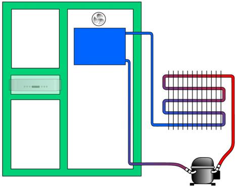
9 Refridgerator compartment Single-circuit cooling system Evaporator behind the air conductor Fan for air circulating
10 Temperature control

11 Air circulation Evaporator
12 Operation freezer compartment press the button for 10 s Temperature setting Setting range 16 C to 21 C
13 Switching the left side of the appliance on and off simultaneously press the and buttons nterior lighting expires Display shows only the refridgerator temperature
14 Fast freeze Press button Freezer compartment temperature is regulated for 24h on -26 C After 24 hours fast freeze switches off by itself
15 Alarm function Button and temperature display flashes Temperatur raises over -3 C With pressing the button the alarm is deactivated for 6h
16 Temperature displays freezer compartment Freezer compartment temperature Temperature display Closed-loop control Super mode Colder than required temperature Between 16 C and the required temperature 1 Between 8 C and 16 C Temperature was previously colder than 16 C Temperature was previously warmer than 8 C Warmer than 8 C Required temperature 1 Required temperature Required temperature Actual temperature Actual temperature Actual temperature
17 Freezer compartment Dual-circuit cooling system Lamellar evaporator Evaporator behind the air conductor Fan for air circulating
18 Dual-circuit cooling system

19 Operation freezer compartment

20 Freezer-compartment air conductor Evaporator with heater Water drain
21 Defrosting the freezer compartment fuzzy control takes over the timing of the defrosting phase The time between two defrosting phases is calculated in such a way that a time of 16 min is set for the defrosting phase The interval between defrosting phases is specified by the electronics module and cannot be influenced

22 Defrosting heater Defrosting heater Condensation pan heater
23 Operation ice maker ain switch ice maker Operation ice cubes Operation crushed ice

24 ce maker Dual-circuit cooling system Evaporator with ice rods
25 Evaporator with ice rods Evaporator ce rod
26 ce rod heater Heater

27 Sensor at the evaporator

28 Sensor in the ice maker compartment

29 Safety temperature limiter Limiter

30 Water bowl

31 Actuation water bowl

32 Water electrodes up K 23 from K Water electrode 2. Common electrode 3. ce electrode 1. Water electrode 2. ce electrode 3. Common electrode
33 ce cubes to big ce electrode ce rod >8mm
34 ce cubes too small ce electrode ce rod <8mm
35 ce cubes too high and too big ce rod ce electrode 8mm

36 Electrodes on the base of the ice maker 10mm
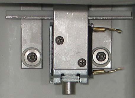
37 Operation water electrodes ce electrode Water electrode Common electrode

38 Operation water electrodes +30% ce electrode Water electrode Common electrode
39 Operation ice maker Switch on the ice maker transformer of the ice maker is actuated temperature in the ice maker must be warmer than 0 C water bowl swings down electric heater on the ice rods is actuated water bowl swings down up
40 R cemaking process Water intake Resistance air ce electrode Resistance water 0 C Water electrode Resistance water 20 C t
41 R cemaking process Cooling water Resistance air ce electrode Resistance water 0 C Water electrode Resistance water 20 C t
42 R cemaking process ce recognition Resistance air ce electrode ce formation at the electrode begins ce recognized Resistance water 0 C Water electrode Resistance water 20 C t
43 R cemaking process cemaking process ends Resistance air Electrode is completely covered in ice ce electrode Resistance water 0 C Water electrode Resistance water 20 C t

44 Finger protection electronics module Finger protection electronic
45 Operation finger protection electronics module Slot LED`s Photodiodes
46 Drinking water preparation Under the ice maker Water tank
47 Operation cool-fresh compartment Switch to the temperature indication for the cool-fresh comp. Temperature setting Setting range 1 C to 8 C
48 Temperatur display Cool-fresh compartment required temperature is displayed
49 Cool-fresh compartment temperature control refrigerated with cold air from the freezer Fan for air circulating Electromechanical air flap

50 Operation cool-fresh compartment Supply airduct behind ice maker Return airduct in the partition to the refridgerator compartment
51 Airduct behind the ice maker Air duct
52 Electromechanical air flap


53 Return airduct cool-fresh compartment Freezer compartment
54 Fan in the cool-fresh compartment Fan Airflap

55 otor compartment Condenser Compressor refridgerator compartment Refrigerant solenoid valve Compressor freezer compartment backside

56 Condenser Refridgerator compartment Freezer compartment

57 Condenser fan Ω
58 Compressor freezer compartment

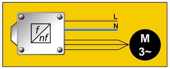
59 Actuation freezer compartment compressor
60 Refridgerator compartment compressor

61 Waste water pump

62 Refrigerating / Freezing Product Division Waste water guidance Condensation water of the freezer compartment
63 Water electrodes up K 21 Safety electrode, 31mm High electrode, 49mm Low electrode, 81mm Common electrode, 127mm
64 Water electrodes from K 22 Safety electrode, 14mm High electrode, 17mm Low electrode, 55mm Common electrode, 60mm
65 Common electrode in the water Waste water pump
66 Low electrode in the water Waste water pump
67 High electrode in the water Waste water pump
68 Water tank empties Waste water pump
69 Safety electrode in the water Waste water pump

70 Water solenoid valve Valve ice maker Valve drinking water

71 Refrigerant solenoid valve
72 Shot-off valve Starting from FD 8002 the shot-off valve is void
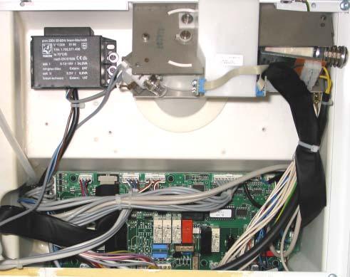
73 Electronics module

74 X105 X200 X201 Refrigerating / Freezing Product Division Electronics module up K 21 X504 X300 X402 X500 X501 X801 X502 X103 X100 X104 X401 X404 X403 X600 X802 nterface X503 X400 X800 X102 X101

75 X105 X200 X201 Refrigerating / Freezing Product Division Electronics module from K 22 X504 X300 X402 X500 X501 X401 X801 X502 X103 X100 X104 X404 X403 X600 X802 nterface X503 X400 X800 X102

76 Vacuum panels 1. Freezer compartment door 2. Left side panel 3. Rear panel 4. Top of the appliance Only appliances K 21 up FD 8003
77 Fault codes On the left side of the display alternating with the temperature indication error messages are spent
78 Faults are displayed in closed-loop control Required water height in the water trough not reached after a water inlet time of 3 min. Waste water alarm Temperature in the freezer compartment warmer than 16 C for longer than 1 week Dust filter in front of the condenser dirty
79 Fault memory The fault codes are saved and can be displayed in the service programm
80 F 1 and F 2 Compartment sensor in the refrigerator compartment Fault code F1 indicates an interrupted sensor and fault code F2 a short-circuited sensor. The fault can be found on the sensor or on the supply cable to the electronics module. f these faults occur, the compartment is operated in an emergency programme
81 F 3 and F 4 Evaporator sensor in the refrigerator compartment Fault code F3 indicates an interrupted sensor and fault code F4 a short-circuited sensor. The fault can be found on the sensor or on the supply cable to the electronics module. f these faults occur, the compartment is operated in an emergency programme
82 F 5 - The set required temperature in the refrigerator compartment was not reached within 24 h Possible causes A large amount of warm food was placed in the compartment. Condenser or dust filter on the base plate dirty. Appliance incorrectly installed Door seal leaking The refrigerator compartment fan is not running The condenser fan is not running or is running too slowly No refrigerant in the refrigerant circuit The compressor is not running
83 F 11 and F 12 - compartment sensor in the freezer compartment Fault code F11 indicates an interrupted sensor and fault code F12 a short-circuited sensor. The fault can be found on the sensor or on the supply cable to the electronics module. f these faults occur, the compartment is operated in an emergency programme
84 F 13 and F 14 Evaporator sensor in the freezer compartment Fault code F13 indicates an interrupted sensor and fault code F14 a short-circuited sensor. The fault can be found on the sensor or on the supply cable to the electronics module. f these faults occur, the compartment is operated in an emergency programme
85 F 15 - Defrosting phase was unsuccessful twice in succession During the defrosting phase the temperature on the evaporator did not become warmer than 12 C twice in succession. Possible causes The defrosting heater is not actuated or is defective The safety thermal cut-out has actuated The evaporator sensor is defective
86 F 16 - evaporator temperature in the freezer compartment did not drop by 1 K within 5 min This fault is only registered if the evaporator temperature is warmer than 6 C and the fan does not run at all or longer than 5 min. Possible causes Shut-off valve does not open The compressor is not running The evaporator sensor is defective No refrigerant in the refrigerant circuit
87 F 21 and F 22 - Compartment sensor in the cool-fresh compartment Fault code F21 indicates an interrupted sensor and fault code F22 a short-circuited sensor. The fault can be found on the sensor or on the supply cable to the electronics module. f these faults occur, the compartment is operated in an emergency programme
88 F 23 - The set required temperature in the cool-fresh compartment has not been reached for 24 h Possible causes The panel in the cool-fresh compartment is not situated on the base of the ice maker The air duct from the freezer compartment has frozen over The equalizing air duct from the cool-fresh compartment to the freezer compartment has frozen over The air flap is frozen to the air duct outlet The cool-fresh compartment fan is not running
89 F 24 - Temperature in the cool-fresh compartment colder than 2 C for15 min Possible causes Air flap does not open Consumption values
90 F 31 and F 32 - ce rod sensor Fault code F31 indicates an interrupted sensor and fault code F32 a short-circuited sensor. The fault can be found on the sensor or on the supply cable to the electronics module.
91 F 33 and F 34 - Compartment sensor in the ice maker Fault code F33 indicates an interrupted sensor and fault code F34 a short-circuited sensor. The fault can be found on the sensor or on the supply cable to the electronics module.
92 F 35 - Temperature in the ice maker colder than 0 C for 2 h Possible causes Check ice-maker cover for leaks The heater is not actuated or is defective Check sensor Check air duct
93 F 37 - Limit switch at bottom is switched on while the water bowl is being swung up This fault occurs only in appliances up to Eprom version 5.02 Possible causes Check limit switches for the water bowl
94 F 39 - Limit switch at top is switched on while the water bowl is being swung down This fault occurs only in appliances up to Eprom version 5.02 Possible causes Check limit switches for the water bowl
95 F 40 - n the descaling programme the temperature on the ice rod has not risen above 5 C for 5 min This fault occurs only in appliances from K 22 and Eprom version 6.01 Possible causes The heater is not actuated or is defective Safety thermal cut-out has actuated Check sensor The refrigerant solenoid valve does not switch over n addition to this error message, fault code F46 is also output
96 F 41 - Temperature on the ice rod is rising above 1 C during the ice making process This error message indicates a problem in the refrigeration circuit. Possible causes Check sensor Shut-off valve does not open The compressor is not running No refrigerant in the refrigerant circuit Fault codes F16 or F31 may also be displayed.
97 F 43 - Required water height in the water bowl not reached after a water inlet time of 3 min Possible causes No water supply Water valve does not open Supply hose in the water bowl has frozen over Water electrodes are not being detected
98 F 44 - Temperature on the ice rod remains above 0 C for 1 h during the ice making process Possible causes Check sensor Shut-off valve does not open The refrigerant solenoid valve does not switch over No refrigerant in the refrigerant circuit
99 F 45 - Duration of ice production over 3 h Possible causes ce electrodes are not being detected Electronics module defective
100 F 46 - Temperature on the ice rod does not rise above 5 C after 1 h during the defrosting process Possible causes The heater is not actuated or is defective Safety thermal cut-out has actuated Check sensor The refrigerant solenoid valve does not switch over
101 F 47 - Temperature on the ice rod is warmer than 49 C Possible causes The heater is actuated continuously Check sensor
102 F 50 - Waste water alarm The fault is only output if water was detected for longer than 10 min by the safety electrodes on the ice-maker base or the waste water pump. Possible causes Water outlet in the ice maker frozen over Waste water pump is not running Appliance incorrectly installed Electrodes are not being detected
103 F 51 - The value of the reference measurement for the finger protection was too high The measured value during the reference measurement of the finger protection electronics module was too high, even though no LED was lit. Possible causes Too much external light An LED is on
104 F 52 - The value of the reference measurement of the finger protection was too low The measured value during the reference measurement of the finger protection electronics module was higher with actuated LED than the value without LED. Possible causes Plug X504 on the electronics module has not been plugged in properly ce dispenser slot dirty Finger protection electronics module defective
105 F 53 - The measured value of the finger protection electronics module without LED was too high during operation The fault can only occur when the ice dispenser button is actuated. The measured value on the photodiode was too high, even though no LED was actuated. Possible causes Too much external light An LED is on
106 F 54 - Comparison measurement of the photodiodes during the reference measurement of the finger protection The measured values of all photodiodes are compared with each other. Die esswerte aller Fotodioden werden miteinander verglichen. Treten f there are differences, this error message is output. dabei Abweichungen auf wird diese Fehlermeldung ausgegeben. Possible causes ce dispenser slot dirty Water droplets on the photodiode Too much external light LED fitted at an angle to the circuit board Finger protection electronics module defective
107 F 55 - The measured values from the comparison measurement of the photodiodes are outside the tolerance Possible causes Electronics module defective
108 F 60 - The low electrode in the waste water container is continuously detecting water Due to the low electrode in the waste water container, the electronics Die esswerte aller Fotodioden werden miteinander verglichen. Treten module is continuously detecting water dabei Abweichungen auf wird diese Fehlermeldung ausgegeben. Possible causes Waste water pump is not running Safety electrodes in the ice-maker base are in the water
109 F 61 - The low electrode in the waste water container is detectingnowater Due to the low electrode in the waste water container, the electronics Die esswerte aller Fotodioden werden miteinander verglichen. Treten module is detecting no water dabei Abweichungen auf wird diese Fehlermeldung ausgegeben. Possible causes Waste water pump is not running Safety electrodes in the ice-maker base are in the water
110 F 62 - The high electrode in the waste water container is continuously detecting water Due to the high electrode in the waste water container, the electronics Die esswerte aller Fotodioden werden miteinander verglichen. Treten module is continuously detecting water dabei Abweichungen auf wird diese Fehlermeldung ausgegeben. Possible causes Safety electrodes in the ice-maker base are in the water
111 F 63 - The high electrode in the waste water container is detecting no water Due to the high electrode in the waste water container, the electronics Die esswerte aller Fotodioden werden miteinander verglichen. Treten module is detecting no water dabei Abweichungen auf wird diese Fehlermeldung ausgegeben. Possible causes Safety electrodes in the ice-maker base are in the water
112 F 64 - Electrodes on the water bowl are not being detected The water bowl was swung down min. 3 times without water being Die esswerte aller Fotodioden werden miteinander verglichen. Treten detected by the electrodes dabei Abweichungen auf wird diese Fehlermeldung ausgegeben. Possible causes Electrodes are not being detected This fault occurs only in appliances up to K 22 and Eprom version 5.02.
113 F 69 - Evaporator temperature in the freezer compartment did not drop by 1K 4 times within 5 min The electronics module detects that fault F 16 has already been output Die esswerte aller Fotodioden werden miteinander verglichen. Treten 4 times and outputs fault code F 69. dabei Abweichungen auf wird diese Fehlermeldung ausgegeben. Possible causes The refrigerant solenoid valve does not switch over Shut-off valve does not open No refrigerant in the refrigerant circuit The compressor is not running This fault is displayed as F 75 in closed-loop control.
114 F 72 - Clean the dust filter This error message requires the customer to clean the dust filter in Die esswerte aller Fotodioden werden miteinander verglichen. Treten front of the condenser. dabei Abweichungen auf wird diese Fehlermeldung ausgegeben. F 72 is not displayed but FL.
115 F 75 - Temperature in the freezer compartment warmer than -16 C for longer than 1 week This fault is stored as F 69 in the fault memory of the service Die esswerte aller Fotodioden werden miteinander verglichen. Treten programme. dabei Abweichungen auf wird diese Fehlermeldung ausgegeben. Possible causes Ambient temperature is warmer than 43 C Condenser or dust filter on the base plate dirty. Appliance incorrectly installed The condenser fan is not running The freezer compartment sensor is defective The freezer compartment fan is not running
116 Serviceprogramme Simultaneously press buttons To terminate press button
117 Navigation in the serviceprogramme Next position Previous position Raise value Reduce value
118 Display in the serviceprogramme Value Position
119 Position Defrosting the freezer compartment A defrosting phase can be started by entering a 1 Value 00 Defrosting is not running 01 Defrosting is required but is currently not possible as the ice maker is running 02 Defrosting is running
120 Position till The current temperature value of the sensors are displayed in C Display 01 Compartment sensor, refrigerator compartment 02 Evaporator sensor, refrigerator compartment 03 Compartment sensor, freezer compartment 04 Evaporator sensor, freezer compartment 05 Compartment sensor, ice maker 07 Evaporator sensor, ice rod 08 Compartment sensor, cool-fresh compartment
121 Position till Correction values Display 11 Compartment sensor, refrigerator compartment 12 Evaporator sensor, refrigerator compartment 13 Compartment sensor, freezer compartment 14 Evaporator sensor, freezer compartment 15 Compartment sensor, ice maker 17 Evaporator sensor, ice rod 18 Compartment sensor, cool-fresh compartment
122 Correction values of the temperature sensors The correction values have been set at the factory. t is not usually necessary to change these values.
123 Change of the correction values Example: The measured value is 2 C colder than the displayed value. The correction value must be changed to 2. Old value: 2 New value: 4 The value must be changed by 2. ( 2 2 = 4) Old value: +2 New value: 0 The value must be changed by 2. (+2 2 = 0) Old value: 2 New value: +1 The value must be changed by +3. ( 2 +3 = +1)
124 Position till onitoring of the temperature sensors on short-circuit value 0 Sensor in measuring range - value 1 Fault detected Anzeige 21 Refrigerator compartment sensor short-circuited 22 Refrigerator compartment evaporator sensor short-circuited 23 Freezer compartment sensor short-circuited 24 Freezer compartment evaporator sensor short-circuited 25 ce maker compartment sensor short-circuited 27 ce rod evaporator sensor short-circuited 28 Cool-fresh compartment sensor short-circuited
125 Position till onitoring of the temperature sensors on interruption value 0 Sensor in measuring range - value 1 Fault detected Display 31 Refrigerator compartment sensor interrupted 32 Refrigerator compartment evaporator sensor interrupted 33 Freezer compartment sensor interrupted 34 Freezer compartment evaporator sensor interrupted 35 ce maker compartment sensor interrupted 37 ce rod evaporator sensor interrupted 38 Cool-fresh compartment sensor interrupted
126 Position till ce maker inputs and outputs of the electronics module Value 0 nput not detected or output not actuated1 Value 1 nput detected or output actuated
127 Position Position 41 till Water detected on the water electrode 42 No water, ice or air detected on the ice electrode 43 Upper water trough limit switch has been actuated 44 Lower water trough limit switch has been actuated 45 ce dispenser limit switch actuated 46 Refrigerant solenoid valve is positioned towards the ice maker evaporator 47 Drinking water dispenser button pressed 48 ce dispenser button pressed 49 Waste water alarmis emitted by the safety electrode of the waste water pump or by the electrodes in the base of the ice maker
128 Position till Defrost in the freezer compartment Hours and minutes are displayed alternately Display 50 Time until next defrosting phase depending on the door opening frequency 51 Time between two defrosting phases depending on the door opening frequency 52 Time until next defrosting phase depending on the fan running time 53 Time between two defrosting phases depending on the fan running time 54 Time until the next defrosting phase Only within the first 10 to 15 days following start-up
129 Position till Doorswitch Value 0 Contact open Value 1 Contact closed Display 56 Reed switch, freezer compartment 57 Reed switch, cool-fresh compartment 58 Reed switch, refrigerator compartment
130 Position till Time - controlled ice making With entering a 1 in Pos. 60 and 62 the biza circuit is activated Display 60 Time-controlled filling of the water trough, this function is switched on by entering a 1 61 Filling time of the water trough factory setting 50 s 62 Time-controlled ice maker this function is switched on by entering a 1 63 Time required to make ice factory setting 40 min. 64 inimum resistance value for ice detection the value is between 10 Ω and 80 Ω
131 Position Statuses of the ice maker Program sequence of the ice preparing can be examined
132 Sequence of ice maker Display 01 Wait until the temperature in the ice maker is warmer than 0 C 02 Swing down the water bowl 03 ce rods are being heated 04 Up version 5.01 Swing up water bowl From version 5.02 Wait until defrosting ends and freezer compartment temperature is cold enough 05 From Eprom version 5.01 Swing up water bowl 10 Fill with water until the water level is detected by the electrodes 11 The water valve remains actuated for 30 % of the previously required filling time 12 Water filling is time-controlled only if a 1 was entered in Pos ce maker 21 ce detection, ice is touching the ice electrode 22 The increase in the resistance value is monitored until the electrode is completely covered in ice 23 ce maker is time-controlled only if a 1 was entered in Pos ce maker off
133 Position till Values on the electrodes 850Ω Air Ω Water Display 66 Value which is measured on the ice electrode 67 Value which is measured on the water electrode 68 Resistance difference between the values from Pos. 66 and Resistance value of ice detection
134 Position Limit temperature foe ice rod heater During the ice production if this temperature at the ice pin is fallen below, then against heating temperature becomes with the ice pin heating Range of adjustment: -30 to -0 Value 15 or -10
135 Position and nterval until FL is displayed Basic setting 8 weeks Display 71 Setting range 1 to 99 weeks 72 Remaining time until display is activated
136 Position easured value of the photodiode for finger protection Not relevant to customer service Also from Eprom version 5.02 Fault E40 Waste water pump actuated 3 times for no reason Fault E41 Waste water pump actuated 4 times for no reason From Eprom Version 6.02 Fault E40 = E60 Fault E41 = E61
137 Position Value of the waste water electrodes The setpoint value and the actual value are displayed alternately < 210 corresponds to air > 210 corresponds to water Display E0 Low electrode E1 High electrode E2 Safety electrodes From Eprom version 6.02 E2 Electrode safety electrode in the waste water container E3 Electrode safety electrode on the base of the ice maker
138 Positionen and Control compressor freezer compartment Display 75 E0 Relative ON duration of the compressor as a % E1 Limiting value of the relative ON duration from which the shut-off valve remains open 76 Time in h that the air temperature in the freezer compartment was above 16 C
139 Position Reference measurement of the finger protection electronics A reference measurement can be started by registering a 1 Anzeige 0 No measurement active 1 Reference measurement is running 2 Reference measurement was not successful, defective finger protection or electronics module
140 Position Shut-off valve By registering a 1 the valve remains always opened Display 0 s actuated depending on the relative ON duration of the compressor 1 Valve remains permanently open
141 Position Demonstration circuit By registering a 1 the demonstration circuit switched on Display 0 Demonstration circuit switched off 1 Demonstration circuit switched on
142 Position Fault memory The fault and the frequency of the fault are indicated alternately on the left side of the display f no fault has been saved, F 0 and 0 are displayed alternately emory forwards emory backwards
143 Position Delete all entries in the fault memory By registering a 1 and go to the next position The fault memoray is deleted
144 Component test programme Within the first 7 s after switching on the appliance simultaneously press buttons The component test programme is ended switching off the appliance
145 Selecting the programme The display changes from to
146 Display nput Output
147 Outputs of the electronics module Next output Previous output
148 Switch the output on Switch the output on or off Decimal points in the display shine
149 Output Output Function Cool-fresh compartment lightfrom Eprom version 5.02 Cool-fresh compartment and refrigerator compartment light Cool-fresh compartment fan Lifting magnet for the air flap in the cool-fresh compartment Up to Eprom version 6.01 refrigerator compartment light Refrigerator compartment fan Refrigerator compartment compressor Condenser fan Freezer compartment and ice maker compressor Shut-off valve Freezer compartment fan Freezer compartment heater Freezer compartment light Transformer for ice maker ce maker heater
150 Output Output Function ce rods heater Water trough downwards swivel motor Water trough upwards swivel motor Water inlet valve for ice maker Lifting motor for the water trough Refrigerant solenoid valve ce maker evaporator is actuated Lifting magnet for crushed ice is actuated Warning! Finger protection is off Drive motor for dispenser spindle Warning! Finger protection is off Water inlet valve for drinking water Waste water pump
151 ntputs of the electronics module Next input Previous input
152 Display of the value Alternately the position and the value of the selected input is shown
153 nputs nput E 0 E 1 E 2 E 3 E 4 E 5 E 6 E 7 E 8 E 9 E 10 E 11 E 12 E 13 Function Compartment sensor, refrigerator compartment Evaporator sensor, refrigerator compartment Compartment sensor, freezer compartment Evaporator sensor, freezer compartment Compartment sensor, ice maker Compartment temperature Evaporator sensor, ice rod Compartment sensor, cool-fresh compartment Switch, drinking water dispenser Switch, ice dispenser Switch, lower water bowl Switch, upper water bowl Switch, ice dispenser full Door switch, freezer compartment Value C C C C C C C C 0=off, 1=on 0=off, 1=on 0=off, 1=on 0=off, 1=on 0=off, 1=on 0=off, 1=on
154 nputs nput E 14 E 15 E 16 E 17 E 18 E 19 E 20 E 21 Function Door switch, refrigerator compartment Door switch, cool-fresh compartment ce electrode Water electrode, ice cube tray Waste water electrode high Waste water electrode low Up to Eprom version 5.02 Safety electrode in the waste water container or on the base of the ice maker From Eprom version 6.01 Safety electrode in the waste water container From Eprom version 6.01 Safety electrode on the base of the ice maker Value 0=off, 1=on 0=off, 1=on Ω Ω Ω Ω Ω Ω
155 Self-diagnosis programme Within the first 7 s after switching on the appliance Simultaneously press buttons The component test programme is ended switching off the appliance
156 Selecting the self-diagnosis programme Display changes from to
157 Navigation in the self-diagnosis programme Program forward Program backward Program start
158 Self-diagnosis programme Total diagnosis Waste water diagnosis programme ce maker diagnosis programme Refrigerator compartment diagnosis programme Freezer compartment diagnosis programme Noises diagnosis programme
159 Display in the self-diagnosis programme Diagnosis programme aktiv Diagnosis programme 1 has been selected Number of the test step is displayed Fault is detected in the test step Diagnosis programme ends without a fault
160 Total diagnosis programme The total diagnosis programme consists of programmes 2 to 5.
161 Waste water diagnosis programme Check all electrodes Function of the waste water system is examined
162 ce maker diagnosis programme Check heater for the ice rods Check electrodes of the water bowl Check water circuit of the ice maker Check sensor Check refridgerant circuit
163 Refrigerator compartment diagnosis programme Check door switch Check sensor Check refridgerant circuit
164 Freezer compartment diagnosis programme Check door switch Check sensor Check refridgerant circuit
165 Noises diagnosis programme All components are headed for 10s
166 Long-term diagnosis programme Appliances from K 22 and from FD 8106 Duration 12 hours During normal closed-loop control Assistance with the error tracing
167 Start long-term diagnosis programme During normal closed-loop control Simultaneously press buttons The test programme is ended switching off the appliance
168 Long-term diagnosis programme Refrigerator compartment diagnosis programme Freezer compartment diagnosis programme Cool-fresh compartment diagnosis programme ce maker diagnosis programme
169 Display in the long-term diagnosis programme Diagnosis programme aktiv Alternating the diagnostic step and the program number are indicated Diagnosis programme ends without a fault All recognized errors are indicated alternating on the left side
170 Non-tested inputs and outputs nput Output Reed contacts of the door switches Limit switch on the water bowl for the height of the ice Safety electrode on the water bowl Light Lifting magnet for crushed ice Spindle motor for the ice dispenser Water valve for drinking water
171 Error displays in the long-term diagnosis programme The indicated fault should be further tested with the aid of the component test programme.
172 Descaling programme Appliances from K 22 and Eprom version 6.01 Duration 12 hours Function of the appliance remains up to the ice preparing

173 Descaling programme Descaler, aterial nr fill in here

174 Start the descaling programme Hold down the and button for 5 s s displayed The descaling programme cannot be ended or interrupted
175 Technical changes K 21 Date Changes ain control with Eprom 5.00 ain control with Eprom 5.01 Shut-off valve not applicable Eprom 5.02 (from ) Vacuum panels not applicable New dust filter Finefilter in the waterinlet (aterial nr ) New heater in the ice maker compartment New aterial for the water bowl New FKF fan with ball bearing New refrigerant valve with sintered filter (Aweco) New transformer for electronics module ce screw made of stainless steel wire New interference suppressor filter
176 Technical changes K 22 Date Change New waste-water area with overflow tray and new waste-water pump Eprom 6.00 Eprom 6.01 (from )
177 Technical changes K 23 Date Change Water bowl with connecting-rod drive and new cam
178 Technical changes K 24 Date Change ce-maker evaporator with soldered-on ice rods New freezer compartment compressor, Zanussi GT 80 RSE New condenser fan, max. speed 700 r.p.m.
179 Technical changes K 25 Date Change Coated ice-maker evaporator Eprom 6.02 (from )
180 Fault diagnostics g
181 Checking the installation location Panel 150mm to 160mm


182 Checking the carcass of the appliance

183 Checking the condensation outlet

184 Checking the condenser fan

185 Checking the light agnet
186 Checking the sensor measure the resistance of the sensor measure the resistance of the sensor at the electronocs
187 Check the fan Switch on the fan with the aid of the component test programme Check the funktion of the fan


188 Checking the fan in the cool-fresh compartment Foam strips

189 Checking the defrosting heater in the freezer compartment
190 Checking the shut-off valve

191 Checking the refrigerant solenoid valve

192 Refrigerant circuit leaking Switch on the compressor onitor the evaporator temperature

193 Checking the air flap in the cool-fresh compartment
194 Compressor for the freezer compartment does not run
195 Compressor for the refrigerator compartment does not run

196 Checking the ice maker

197 Passivation coating on the electrodes The electrodes must be free of deposits
198 Accumulation of mud in the ice maker ud and alga formation under the ice-maker Sanitation of the appliance
199 Sanitation Garden pump
Service Information. WNes 2956 appliance documentation. Service Information no. 27/2004 LHG/TKD-Fe/June SI
 After Sales Service International Service Information Service Information no. 27/2004 LHG/TKD-Fe/June 2004 WNes 2956 appliance documentation Page 1/26 Contents 2.0. Extract from Operating Instructions
1 SAFETY INSTALLATION OPERATION REPAIR COMPONENTS FUNCTIONS... 12
 1 SAFETY... 3 1.1 Safety instructions... 3 1.2 Repair instructions... 3 2 INSTALLATION... 4 3 OPERATION... 5 3.1 Freezer Set button... 5 3.2 Refrigerator Set button... 5 3.3 Super Cool button... 5 3.4
Service Documentation
 After Sales Service International Service Documentation Service Manual No. 22/2008 Version 01 LHG/KDT-Ne/30.08.10 Appliance Documentation SBSes 7273 from Index 20 PremiumPlus comprising: SKBes 4212 from
Side-by-side combined refrigerator-freezer
 REPAIR INSTTRUCTTI I IONS Side-by-side combined refrigerator-freezer 1 SAFETY... 2 4.1 Electronic controller... 8 1.1 Safety instructions... 2 1.2 Repair instructions... 2 2 INSTALLATION... 3 3 OPERATION...
SERVICE MANUAL REFRIGERATION
 SERVICE MANUAL REFRIGERATION ELECTROLUX HOME PRODUCTS S.p.A. Publication no. Spares Operations Italy 599 37 75-07 Corso Lino Zanussi, 30 060824 I - 33080 PORCIA / PN (ITALY) ITZ/SERVICE/AA Fax +39 0434
2 INSTALLATION OPERATION FUNCTIONS SAFETY Compressor Compartment... 10
 REPAIR INSTTRUCTTI I ION REFFRI IGERATTOR 1 SAFETY... 3 4.1 Compressor Compartment... 10 2 INSTALLATION... 4 4.2 Fridge Evaporator Compartment... 11 4.3 Freezer Evaporator Compartment... 12 3 OPERATION...
Refrigerator KE T
 Refrigerator KE 680-1-3T Service Manual: H8-74-07 Responsible: U. Laarmann KÜPPERSBUSCH HAUSGERÄTE AG E-mail: uwe.laarmann@kueppersbusch.de Tel.: (0209) 401-732 Customer Service Fax: (0209) 401-743 Postfach
SERVICE MANUAL REFRIGERATION
 SERVICE MANUAL REFRIGERATION Electrolux Home Products S.p.A. Spares Operations Italy Corso lino Zanussi, 30 I - 33080 Porcia (PN) Fax +39 0434 394096 S.O.I. Edition: 10.2006 Publication no. 599 38 38-50
4. ALIGNMENT AND ADJUSTMENTS
 4-1) Forced Operation Function (Pull-down / Refrigerator Defrost / Refrigerator. Freezer-Defrost / Cancellation) 28 4-2) Sound function 29 4-3) Exhibition Function 29 4-4) Self-Diagnostics Function29 4-5)
Service Documentation
 After Sales Service International Service Manual No. 16/2010 Service Documentation LWL/KDT-baj/30.06.10 Appliance Documentation GKv 4310 / 4360 from Index 20 Commercial refrigerator, ventilated GKv 5730
Fast Track Troubleshooting
 Fast Track Troubleshooting Model: RH22** Bulletins: IMPORTANT SAFETY NOTICE For Technicians Only This service data sheet is intended for use by persons having electrical, electronic, and mechanical experience
SERVICE MANUAL REFRIGERATION
 SERVICE MANUAL REFRIGERATION ELECTROLUX ZANUSSI S.p.A. Publication No. Spares Operations Italy 599 35 40-29 Corso Lino Zanussi, 30 020806 I - 33080 PORCIA / PN (ITALY) ITZ/SERVICE/AA EUROFLEC With exposed
OPERATING INSTRUCTIONS CAFITESSE 300
 COFFEE CAUTION: HOT LIQUIDS / PRECAUCION! LIQUIDO CALIENTE Release handle when cup is 3/4 full / Deje de actuar el mango cuando la taza está llenada por 3/4 OPERATING INSTRUCTIONS CAFITESSE 300 B-2226
3. OPERATING INSTRUCTIONS & INSTALLATION
 3-1) Digital Panel 20 3-2) Temperature Control Function 20 3-3) Power Freeze and Power Cool Functions 21 3-4) Child Lock Function 21 3-5) Ice & Water Dispenser Function 22 3-6) C-Fan Motor Delay Function
IKS..10,..20 / IK..00 / EK..10 from Index 20. IKS..14,..24 / IK..04 / EK..14 from Index 20, with 4-star freezer compartment
 After Sales Service International Service Information No. 03/2006 Service Information LHG/TKD-Ne/06.04.06 Appliance Documentation IKS..10,..20 / IK..00 / EK..10 from Index 20 IKS..14,..24 / IK..04 / EK..14
Fast Track Troubleshooting
 Fast Track Troubleshooting Models Covered: RS263BBBB/XAA RS263BBSH/XAA RS263BBWP/XAA RS265LBBP/XAA RS265LBWP/XAA SxS Refrigeration Notice: Bulletin on parts change Thermal Fuse to Bi-Metal Publication
GKv 5710 / 5760 GKv 6410 / 6460
 After Sales Service International Service Manual No. 21/2007 (version 01) Service Information LWL/KDT/baj/14.05.07 Appliance Documentation GKv 5710 / 5760 GKv 6410 / 6460 Refrigerator for the catering
Fast Track Troubleshooting
 Fast Track Troubleshooting Models Covered: RF197ACPN French Door Refrigeration IMPORTANT SAFETY NOTICE For Technicians Only This service data sheet is intended for use by persons having electrical, electronic,
Essentia Project Artica Platform No Frost 60 cm Appliances 2011
 Essentia Project Artica Platform No Frost 60 cm Appliances 2011 Event Ca Maiano, May 2011 Presenter Piotr Kelm Francesco Nieli 0 Legend and User Interface Legend THR3 Interface (SQG_CL_32) MID Indesit
MR3CCUHV Temperature/Defrost Control
 Master Catalog 125 Temperature Controls Section A Product/Technical Bulletin Issue Date 0401 MR3CCUHV Temperature/Defrost Control The MR3CCUHV Temperature/Defrost Control is designed to control the temperature
B/S/H/ Fault Codes and Service Programmes PG
 LED LED LED off E:00 No error - - - - - - h:00 h:24 No error Appliance does not start Delay timer is activated! No appliance fault! All LED s are on LED s flashing Interface error Appliance without function
Model Number Nomemclature... 1 Specifications... 3 Refrigeration System... 4 Freezer and Refrigerator Air Circulation... 5 Display Designs...
 Samsung AD Refrigerator Familiarization Maytag Technical Training Services 2004 ABS-L2004-012 Model Number Nomemclature... 1 Specifications... 3 Refrigeration System... 4 Freezer and Refrigerator Air
4. Alignment and Adjustments
 . Alignment and Adjustments -) Forced Operation Function (Pull-down / Refrigerator Defrost / Refrigerator. Freezer-Defrost / Cancellation) 3 -) Self-Diagnostics Function 3-3) Load Operation Check Function
Descriptive Technical Documentation. DTD no
 Descriptive Technical Documentation - Model-dependent - DTD no. 37-1901 Model(s): F 1411 Vi [USA-CAN], F 1801 Vi [USA-CAN], F 1811 Vi [USA-CAN], F 1901 Vi [USA-CAN], F 1911 Vi [USA-CAN], F 1411 SF [USA-CAN],
Scotsman Technical Training. CU50 Cube Ice Machine
 Scotsman Technical Training CU50 Cube Ice Machine Major Topics Overview Installation Start Up Sequence of Operation Maintenance Diagnostics Service Procedures Models Two Base Models Gravity Drain Pump
ICE MAKER DIAGNOSTIC SERVICE MANUAL
 ]1DOmeticl Dometic ICE MAKER DIAGNOSTIC SERVICE MANUAL The Dometic Corporation Corporate Office 2320 Industrial Parkway Elkhart, IN 46515 21 g-295-5228 Warranty Department Technical Services Department
Service Manual. KB (ef, es) 4310 from 20A. Comfort, A+++ Refrigerator with BioFresh Compartment. Edition 01 Date: Translation of Original
 4310 from 20A. Comfort, A+++ Refrigerator with BioFresh Compartment. Edition 01 Date: Translation of Original") KB (ef, es) 4310 from 20A Comfort, A+++ Refrigerator with BioFresh Compartment Edition 01 Date: 16.08.2016 Translation of Original Liebherr-Hausgeräte Ochsenhausen GmbH Document info and key to changes
KB (ef, es) 4310 from 20A Comfort, A+++ Refrigerator with BioFresh Compartment Edition 01 Date: 16.08.2016 Translation of Original Liebherr-Hausgeräte Ochsenhausen GmbH Document info and key to changes
Ice Maker (Fresh Food Compartment)
") Ice Maker (Fresh Food Compartment) The Ice Maker is located in the fresh food compartment in models featuring a dispenser in the left side door. Models without the dispenser will have the Ice Maker mounted
Ice Maker (Fresh Food Compartment) The Ice Maker is located in the fresh food compartment in models featuring a dispenser in the left side door. Models without the dispenser will have the Ice Maker mounted
B/S/H/ Error codes and service programmes PW
 1 ERROR CODES AND APPLIANCE MESSAGES...2 1.1 Error codes... 2 OPEN... 2 E01... 2 E02... 2 E04... 2 E05... 2 E06... 2 E10... 3 E11... 3 E12... 3 E13... 3 E14... 4 E16... 4 E17... 4 E20... 4 E25... 4 E26...
Service Quick Guide SQG_CL_15/01_EN
 Service Quick Guide SQG_CL_15/01_EN Indesit Company, Service Department Table - New Platform 2005 Electronic Refrigerators, combination and double-door 1 LED1 LED2 LED3 2 Table 1 In the case of the Led
Fast Track Troubleshooting
 Fast Track Troubleshooting Models Covered: RF195AC**/XAA RF197AC**/XAA RF217AC**/XAA IMPORTANT SAFETY NOTICE For Technicians Only This service data sheet is intended for use by persons having electrical,
CAUTION. No-Load Performance, Controls in Normal Position
 Side-by-Side Refrigerator Technical Information JCD2292KT* JCD2292KT*2, JCD2295KE* JCD2295KE*2, JCD2297KE* JCD2297KE*2, JSD2695KES JSD2695KES2, JSD2695KG* JSD2695KG*0, JSD2697KE* JSD2697KE*2, MSD2660KEG*
SERVICE MANUAL New Electronic Cold Platform 2005.
 SERVICE MANUAL New Electronic Cold Platform 2005. All the parts included in this document are the property of Indesit Company S.p.A. All rights reserved. This document and the information it contains are
LCD on door ERF 2000 SERVICE INSTRUCTION COLD. Fridge/Freezer with electronic control. Publication number
 SERVICE INSTRUCTION COLD Fridge/Freezer with electronic control B DISTRIPARTS AB BOX 501 S-562 80 NORRAHAMMAR TEL 036-31 80 00 Telefax 036-31 81 10 Telefax 036-31 80 88 Publication number 599 52 06-72
Installation and Operation Guide For MCF-49FD, MCF-23FD MCR-49FD, MCR-23FD
 Installation and Operation Guide For MCF-49FD, MCF-23FD MCR-49FD, MCR-23FD CONTENTS 1. SPECIFICATIONS 2. SERIAL NUMBER 3. INSTALLATION 4. CLEANING 5. CAUTION 6. BASIC OPERATION 6-1. REFRIGERATOR 6-2. FREEZER
NO. F ISSUED: JUN. 15, 2009 REVISED: HOSHIZAKI MODULAR CRESCENT CUBER KMD-201AA KMD-201AWA MODEL SERVICE MANUAL
 NO. F037-775 ISSUED: JUN. 15, 2009 REVISED: HOSHIZAKI MODULAR CRESCENT CUBER MODEL KMD-201AA KMD-201AWA SERVICE MANUAL CONTENTS PAGE I. SPECIFICATIONS ---------------------------------------------------------------------------------------
Due to a possibility of personal injury or property damage, always contact an authorized technician for service or repair of this refrigerator.
 Bottom Mount Refrigerator Technical Information Due to a possibility of personal injury or property damage, always contact an authorized technician for service or repair of this refrigerator.! CAUTION
SERVICE INSTRUCTION. DYNAMIC COOLING with 0 zone REFRIGERATION. Fridge/freezer with. Publication number
 SERVICE INSTRUCTION REFRIGERATION DISTRIPARTS AB BOX 501 S-562 80 NORRAHAMMAR Phone 036-31 80 00 Telefax 036-31 81 10 Telefax 036-31 80 88 Publication number 599 51 96-71 Rev. 04-04-20 SV/SERVICE DT/MA/AN
Operating instructions
 Operating instructions for Winterhalter Gastronom dishwasher GS 502 and GS 515 Contents Page 1 Intended use... 1 2 Installation and commissioning... 1 3 Safety instructions... 2 4 Operating panel... 3
Instructions for use
 Instructions for use ENGLISH Instructions for use Page 3 2 INDEX Chapter 1: INSTALLATION...4 1.1. INSTALLING SINGLE APPLIANCE...4 1.2. INSTALLING TWO APPLIANCES...4 1.3. ADJUST DOORS (If available)...4
1. SAFETY WARNINGS INSTALLTION Location Reversing the Door Swing Levelling the Unit... 3
 Contents 1. SAFETY WARNINGS... 1 2. INSTALLTION... 2 2.1 Location... 2 2.2 Reversing the Door Swing... 2 2.3 Levelling the Unit... 3 2.4 Cleaning Before Use... 3 2.5 Before Using Your Unit... CE BC108
JBL2088HES JBL2088HES0, JBR2088HES JBR2088HES0, JFC2089HEP JFC2089HEP0, JFC2089HES JFC2089HES0, JFC2089HPF JFC2089HPF0, JFC2089HPY JFC2089HPY0
 Bottom Mount Refrigerator Technical Information JBL2088HES JBL2088HES0, JBR2088HES JBR2088HES0, JFC2089HEP JFC2089HEP0, JFC2089HES JFC2089HES0, JFC2089HPF JFC2089HPF0, JFC2089HPY JFC2089HPY0 Due to a possibility
 1 of 5 3/1/2012 9:32 AM Understanding Your Ice Maker A discussion covering the operation and troubleshooting of ice makers both stand-alone units and those built into absorption refrigerators. Ice maker
Operation Manual SCT14B and SCT18B. Inspection. 3 General Description. 3 General Requirements. 3 Standard Features.
 Spot Cooling Systems, Inc. 120 Century Drive Suite 00 Carrollton, TX 7006 00-6-776 Operation Manual SCT1B and SCT1B Warning! Improper installation, adjustment, alteration, service, or maintenance can cause
Bottom Mount Refrigerator---Technical Information
 Bottom Mount Refrigerator---Technical Information WARNING Electrical Shock Hazard Disconnect power before servicing. Replace all parts and panels before operation. Failure to do so can result in death
Fast Track Troubleshooting
 Fast Track Troubleshooting Models Covered: RF266AD**/XAA French Door Refrigeration IMPORTANT SAFETY NOTICE For Technicians Only This service data sheet is intended for use by persons having electrical,
Fast Track Troubleshooting
 Models Covered: RF266AA**/XAA RF266AB**/XAA RF266**/XAA French Door Refrigeration NOTICE: RF266AA & AB** 01/09 Parts Change: Refer to bulletin. All Water Tank Parts Forced Mode: Press the Pwr Freeze Fridge
Fast Track Troubleshooting
 Fast Track Troubleshooting Models Covered: RS267TDBP/XAA RS267TDPN/XAA RS267TDRS/XAA RS267TDWP/XAA NOTICE: RS267TD PN & RS Colors Parts Change: Refer to bulletin. Door Handle Parts Change IMPORTANT SAFETY
OPERATING INSTRUCTIONS B
 OPERATING INSTRUCTIONS B-95 0.2003 Contents CONTENTS Introduction... 2 Safety instructions... 2 Technical data... 4 Dispenser components... 5 Dispenser components / front... 5 Service panel components...
B/S/H/ Fault Codes and Service Programmes PG
 off on E:00 No error - - - - - - h:00 h:24 No error Appliance does not start Delay timer is activated! No appliance! All s are on s flashing Interface error Appliance without function Appliance without
Technical Training Prodigy Undercounter Cubers. Models CU1526, CU2026 and CU3030
 Technical Training Prodigy Undercounter Cubers Models CU1526, CU2026 and CU3030 List of Major Topics Introduction Installation Operation Maintenance Diagnosis Service Prodigy with a Bin 3 models CU1526
PRIMUS IMPORTANT. User Manual and Product Specifications. Portable Fridge/Freezer. Part No. PRI18LP - 18 Litre. Read instructions before operation.
 PRIMUS Portable Fridge/Freezer User Manual and Product Specifications Part No. PRI18LP - 18 Litre IMPORTANT Read instructions before operation. Getting to know your Portable Fridge/Freezer IDENTIFICATION
1 SAFETY REPAIR COMPONENTS FUNCTIONS FAULT DIAGNOSIS X-Cool Side by Side Refrigerator
 1 SAFETY... 3 1.1 Safety instructions... 3 1.2 Repair instructions... 3 2 COMPONENTS... 4 2.1 Overall view... 4 2.2 Compressor room... 4 2.3 Power Control Boards (PCB)... 5 2.4 Temperature sensor... 6
Service Manual for Cuber Model CS0415
 for Cuber Model Introduction This is the service manual for the ice machine. Note and heed any warning symbols where they appear. Basic installation information is provided, however the installation manual
NO. 15FD-742 ISSUED: AUG. 10, 2007 REVISED: SEP. 30, 2013 HOSHIZAKI SELF-CONTAINED CRESCENT CUBER KM-30A KM-35A KM-50A KM-75A MODEL SERVICE MANUAL
 NO. 15FD-742 ISSUED: AUG. 10, 2007 REVISED: SEP. 30, 2013 HOSHIZAKI SELF-CONTAINED CRESCENT CUBER MODEL KM-30A KM-35A KM-50A KM-75A SERVICE MANUAL CONTENTS PAGE I. SPECIFICATIONS--------------------------------------------------------------------------------------1
Technical Description: / Rev, Seq: F, 2 / Date: Remarks. At Customer error case. Blinking LED's at end of Flash process
 Technical Description: 56000000157007 / Rev, Seq: F, 2 / Date: 17.09.2009 Function Actuation Display Remarks Material No. 9000 361 479 Error class (failure group) In Customer Service program At Customer
TABLE OF CONTENTS REFRIGERATOR-FREEZER. Model No. NR-BN34FX1 Model No. NR-BN34FW1
 Order Number GORR1405001CE REFRIGERATOR-FREEZER Model No. NR-BN34FX1 Model No. NR-BN34FW1 Product-Color X:Stainless W:White Destination E(Europe Continental) B(U.K.) TABLE OF CONTENTS PAGE 1 Safety Precautions-----------------------------------------------
FX BLAST CHILLER ISO ISO 9001
 FX BLAST CHILLER ISO 14001 ISO 9001 Contents Environmental Management Policy 1 Disposal Requirements 1 Cabinet description 2 Controller Description Controller Operation 2 to 3 Alarms & Warnings 4 Parameter
AG2TEMP PRESTIGE SPECIAL REFRIGERATOR Model: AG2TEMP SPECIAL
 AG2TEMP PRESTIGE SPECIAL REFRIGERATOR Model: AG2TEMP SPECIAL Arrowsmith and Grant Refrigeration Manufacturers & suppliers of prestige home refrigeration equipment. ABN: 64 007 296 586 28-30 Marni St Dandenong
Service & Parts Manual
 Service & Parts Manual SUB-ZERO FREEZER CO., INC. 000 ALL RIGHTS RESERVED JOB AID #780 (Revision A - Reprinted April/000) GENERAL INFORMATION SECTION GENERAL INFORMATION - GENERAL INFORMATION TABLE OF
Technical Description: / Rev, Seq: H, 1 / Date: Remarks. At Customer error case. Blinking LED's at end of Flash process
 Technical Description: 56000000157007 / Rev, Seq: H, 1 / Date: 29.06.2010 Material No. 9000 361 479 Function Actuation Display Remarks Error class (failure group) In Customer Service program At Customer
Frost Checklist and Troubleshooting Guide for NDA1402 & NEA1402
 Frost Checklist and Troubleshooting Guide for NDA1402 & NEA1402 REFRIGERATOR BULLETIN R82-7A NOVEMBER 2007 USA SERVICE OFFICE Dometic Corporation 2320 Industrial Parkway Elkhart, IN 46516 574-294-2511
NO. F ISSUED: JUN. 18, 2008 REVISED: JUN. 17, 2011 HOSHIZAKI SELF-CONTAINED CRESCENT CUBER KM-100A KM-125A MODEL SERVICE MANUAL
 NO. F003-756 ISSUED: JUN. 18, 2008 REVISED: JUN. 17, 2011 HOSHIZAKI SELF-CTAINED CRESCENT CUBER MODEL KM-100A KM-125A SERVICE MANUAL IMPORTANT This manual should be read carefully before the icemaker is
CABINET PARTS REFRIGERATOR. For Models: GD2SHAXKQ03, GD2SHAXKT03, GD2SHAXKB03 (White) (Biscuit) (Black) 5 02 Litho In U.S.A. (mek) 1. Part No.
 (Biscuit) (Black) 5 02 Litho In U.S.A. (mek) 1. Part No.") CABINET PARTS REFRIGERATOR 5 02 Litho In U.S.A. (mek) 1 Part No. CABINET PARTS 1 LITERATURE PARTS LIT2220699 Use & Care Guide LIT2220104 Service & Wiring Sheet LIT2220300 Energy Guide LIT2220407 Modular
CABINET PARTS REFRIGERATOR 5 02 Litho In U.S.A. (mek) 1 Part No. CABINET PARTS 1 LITERATURE PARTS LIT2220699 Use & Care Guide LIT2220104 Service & Wiring Sheet LIT2220300 Energy Guide LIT2220407 Modular
OPERATING MANUAL AIR CONDITIONER DUCT TYPE. ART Series KEEP THIS MANUAL FOR FUTURE REFERENCE FUJITSU GENERAL LIMITED P/N
 OPERATING MANUAL AIR CONDITIONER DUCT TYPE ART Series KEEP THIS MANUAL FOR FUTURE REFERENCE FUJITSU GENERAL LIMITED P/N9374379293-02 CONTENTS SAFETY PRECAUTIONS... 1 NAME OF PARTS... 2 PREPARATORY OPERATION...
CABINET PARTS. For Models: ED5SHAXMQ00, ED5SHAMXT00, ED5SHAXMB00 (White) (Biscuit) (Black) REFRIGERATOR. Part No Rev.A
 (Biscuit) (Black) REFRIGERATOR. Part No Rev.A") CABINET PARTS REFRIGERATOR 4 04 Printed In U.S.A. (kdj) 1 Part No. Rev.A LITERATURE PARTS 1 LIT2261135 Energy Guide LIT2255705 Owner s Manual LIT2255380 Service & Wiring Sheet LIT2220407 Modular Icemaker
CABINET PARTS REFRIGERATOR 4 04 Printed In U.S.A. (kdj) 1 Part No. Rev.A LITERATURE PARTS 1 LIT2261135 Energy Guide LIT2255705 Owner s Manual LIT2255380 Service & Wiring Sheet LIT2220407 Modular Icemaker
R410A. AIR CONDITIONER DUCT TYPE / ART Series OPERATING MANUAL. REFRIGERANT This Air Conditioner contains and operates with refrigerant R410A.
 AIR CONDITIONER DUCT TYPE / ART Series OPERATING MANUAL KEEP THIS OPERATION MANUAL FOR FUTURE REFERENCE R410A REFRIGERANT This Air Conditioner contains and operates with refrigerant R410A. THIS PRODUCT
55CM Wide Freestanding Under Counter Freezer Instruction Manual
 55CM Wide Freestanding Under Counter Freezer Instruction Manual Model Number: RHUCFZ1 Please read these instructions carefully and keep them for future reference For Customer Services, Spare Parts & Manufacturer
KitchenAid Food Stream Solutions Classic and Integrated Series
 KitchenAid Food Stream Solutions Classic and Integrated Series KitchenAid Chapter list Installation Range overview Installation General Information Function Compressor Power Control Board Defrosting Heating
AFI2538AE* AFI 2538AE*0, MFI2568AE* MFI2568AE*0 CAUTION
 Bottom Mount Refrigerator Technical Information AFI2538AE* AFI 2538AE*0, MFI2568AE* MFI2568AE*0! CAUTION Due to a possibility of personal injury or property damage, always contact an authorized technician
Wired Controller XK60
 Owner's Manual Commercial Air Conditioners Thank you for choosing Commercial Air Conditioners, please read this owner s manual carefully before operation and retain it for future reference. User Notice
Service instruction Cold
 Service instruction Cold AEG 5 18 C C COOLMATIC C C FROSTMATIC SANTO electronic Table of contents SERVICE INSTRUCTION ELECTRONIC CONTROL FLEC 2.3 General 2 1 THE PANEL 2 2 FUNCTIONS 3 3 CABINET START-UP
SERVICE NOTEBOOK BUILT-IN REFRIGERATOR VCSB481 / VCSB482
 SERVICE NOTEBOOK BUILT-IN REFRIGERATOR VCSB481 / VCSB482 VIKING RANGE CORPORATION, PO DRAWER 956, GREENWOOD, MS. 38930-USA TABLE OF CONTENTS Technical Information---------------------------------------------------------------------------
MR4PMUHV Electronic. Temperature/Defrost Control with Relay Pack
 Master Catalog 125 Temperature Controls Section A Product/Technical Bulletin Issue Date 1098 MR4PMUHV Electronic Temperature/Defrost Control with Relay Pack The MR series temperature controls are designed
Commercial Series. Power switch & Nameplate location: NAMEPLATE: Single and Dual Section
 COMMERCIAL SERIES Commercial Series Commercial Series Power switch & Nameplate location: NAMEPLATE: Single and Dual Section Must reach over behind Front Panel to access: Single and Dual Section Commercial
Owner s Manual Super-Slim Four-Way Cassette
 CASSETTE- TYPE AIR CONDITIONER Owner s Manual Super-Slim Four-Way Cassette IMPORTANT NOTE: Read this manual carefully before installing or operating your new air conditioning unit. Make sure to save this
KM-61BAH KM-101BAH KM-151BAH
 NO. M006-749 ISSUED: FEB. 18, 2008 REVISED: JUN. 12, 2008 HOSHIZAKI SELF-CONTAINED CRESCENT CUBER MODEL KM-61BAH KM-101BAH KM-151BAH SERVICE MANUAL IMPORTANT Only qualified service technicians should attempt
CABINET PARTS For Models: ED5RHEXNL00 (Stainless VCM)
") CABINET PARTS REFRIGERATOR 11 06 Litho In U.S.A. (kdj) 1 Part No. 1 LIT2188771 Use & Care Guide LIT2255373 Service & Wiring Sheet LIT2305928 Energy Label LIT628370 Modular Icemaker Service Sheet 2 2174748
CABINET PARTS REFRIGERATOR 11 06 Litho In U.S.A. (kdj) 1 Part No. 1 LIT2188771 Use & Care Guide LIT2255373 Service & Wiring Sheet LIT2305928 Energy Label LIT628370 Modular Icemaker Service Sheet 2 2174748
COMMERCIAL REFRIGERATORS, STAINLESS STEEL PRODUCTS OPERATING INSTRUCTIONS
 COMMERCIAL REFRIGERATORS, STAINLESS STEEL PRODUCTS OPERATING INSTRUCTIONS CE COMMERCIAL REFRIGERATORS Model - S.N.: Volt: 220 Hz: 50 Amps: Watt: Watt (heating element): Fuse Amps: Refrigerant: R gr: Working
PowerPoint Presentation by: Associated Technical Authors. Publisher The Goodheart-Willcox Company, Inc. Tinley Park, Illinois
 Althouse Turnquist Bracciano PowerPoint Presentation by: Associated Technical Authors Publisher The Goodheart-Willcox Company, Inc. Tinley Park, Illinois Chapter 3 Explain the operation of a simple ice
CABINET PARTS REFRIGERATOR. For Models: ED5VHGXMQ00, ED5VHGXMT00, ED5VHGXMB00 (White) (Biscuit) (Black) 8 03 Litho In U.S.A. (kdj)
 (Biscuit) (Black) 8 03 Litho In U.S.A. (kdj)") CABINET PARTS REFRIGERATOR 8 03 Litho In U.S.A. (kdj) 1 Part No. Rev. C CABINET PARTS 1 LIT2220692 Use & Care Guide LIT2255377 Service & Wiring Sheet LIT2260931 Energy Label LIT628370 Modular Icemaker
CABINET PARTS REFRIGERATOR 8 03 Litho In U.S.A. (kdj) 1 Part No. Rev. C CABINET PARTS 1 LIT2220692 Use & Care Guide LIT2255377 Service & Wiring Sheet LIT2260931 Energy Label LIT628370 Modular Icemaker
TCW 2000 Ice liner refrigerator and freezer PIJ
 TCW 2000 Ice liner refrigerator and freezer OVER VIEW The unique rotomoulded Chest Freezer and inclined Refrigerator with two separate compartments and compressors worldwide Hold over time @ 32 C Hold
TECHNICAL INFORMATION T1500 Series Clothes Dryers
 TECHNICAL INFORMATION T1500 Series Clothes Dryers 2003 Miele - Table of Contents 1.0 CONSTRUCTION & DESIGN 1.1 Appliance Overview - Vented 1 1.2 Appliance Overview Condenser Models 2 1.3 Controls Overview
KSD-35 DR11 KUE-35 DVN11
 FLOOR-STANDING TYPE AIR CONDITIONER Owner s Manual Floor-Standing Type KSD-35 DR11 KUE-35 DVN11 IMPORTANT NOTE: Read this manual carefully before installing or operating your new air conditioning unit.
WHIRLPOOL REFRIGERADOR GS2SHGXLQ01
 CABINET, LITERATURE 1 CABINET, LITERATURE 1 LIT2220425 LITERATURE PARTS (Energy Label) 1 LIT2220699 LITERATURE PARTS (Owner`s Manual) 1 LIT2255381 LITERATURE PARTS (Service & Wiring Sheet) 1 LIT628370
1 SAFETY Aqua Stop valve INSTALLATION OPERATION FUNCTIONS REPAIR COMPONENTS
 REPAIR INSTTRUCTTI I ION Dishwasher 1 SAFETY... 3 4.3 Aqua Stop valve... 21 2 INSTALLATION... 4 2.1 Aligning the appliance... 4 2.2 Electrical connection... 4 2.3 Water connection... 4 3 OPERATION... 5
REACH-IN SAFETEMP (-AAC)
") Slide 1 REACH-IN SAFETEMP (-AAC) FH1-AAC RH2-AAC-HD The Hoshizaki line of reach-ins consists of two types of refrigerators and freezers. The high end TEMPGUARD (-SSB) and the mid-range SAFETEMP ( AAC).
Slide 1 REACH-IN SAFETEMP (-AAC) FH1-AAC RH2-AAC-HD The Hoshizaki line of reach-ins consists of two types of refrigerators and freezers. The high end TEMPGUARD (-SSB) and the mid-range SAFETEMP ( AAC).
Refrigeration. Bosch pioneers in design and energy conservation to produce a range of innovative refrigeration products to suit every need.
 Bosch pioneers in design and conservation to produce a range of innovative refrigeration products to suit every need. As well as being pioneers in product design, our commitment to the environment led
PICEM75 Ice Maker & Dispenser
 PICEM75 Ice Maker & Dispenser Countertop Ice Cube Making Machine by DESCRIPTION 1 1 - Viewing Window 2 - Front Cover 3 - LCD Display 2 3 12 4 - Control Panel 5 - Ice Cube Dispenser Shoot 6 - Ice Cube Dispenser
Compact Refrigerator. User's Manual PLEASE READ THIS MANUAL CAREFULLY BEFORE USING YOUR REFRIGERATOR AND KEEP IT FOR FUTURE REFERENCE.
 Compact Refrigerator User's Manual Model MCBR445B2 / MCBR445S2 PLEASE READ THIS MANUAL CAREFULLY BEFORE USING YOUR REFRIGERATOR AND KEEP IT FOR FUTURE REFERENCE. Product Registration Thank you for purchasing
ST Wiring diagram. Product description. Standard temperature controller. Order number
 ST64-31.10 Standard temperature controller Order number 900197.007 Old Id.Nr.: 386169 Wiring diagram Product description The controller ST64-31.10 was developed for simple thermostatic controls. The round
Settings and Maintenance of the CombinAir
 Atmos CombinAir Settings and Maintenance of the CombinAir Issue 13.8.10 Operation and commissioning: The control unit on the front of the CombinAir is used to adjust the settings during commissioning.
Refrigeration Controller Operator s Manual (HRC) PO Box 6183 Kennewick, WA
 PO Box 6183 Kennewick, WA") Refrigeration Controller Operator s Manual (HRC) PO Box 6183 Kennewick, WA 99336 www.jmcvr.com 1-509-586-9893 Table of Contents TABLE OF FIGURES...1 OVERVIEW OF THE HRC CAPABILITIES...2 INSTALLATION AND
Refrigeration Controller Operator s Manual (HRC) PO Box 6183 Kennewick, WA 99336 www.jmcvr.com 1-509-586-9893 Table of Contents TABLE OF FIGURES...1 OVERVIEW OF THE HRC CAPABILITIES...2 INSTALLATION AND
ACTIVE SMART Refrigerator/Freezer. Ice And Water Models E522BRXFDU, E522BRXU, E522BLXFDU, E522BLXU
 ACTIVE SMART Refrigerator/Freezer Service Manual Ice And Water Models E522BRXFDU, E522BRXU, E522BLXFDU, E522BLXU PRODUCT CODES 22128, 22179, 22129, 22184, 22272, 22273, 22296, 22297 SERVICE SUPPLEMENT
DAILY REFERENCE GUIDE
 DAILY REFERENCE GUIDE THANK YOU FOR PURCHASING AN HOTPOINT PRODUCT To receive more comprehensive help and support, please register your product at www. hotpoint. eu/ register WWW EN You can download the
Portable Refrigerator
 Portable Refrigerator Owners Manual Single door 40 litre 65 litre 80 litre 125 litre Double door 74 litre 95 litre 2009 Introduction The National Luna range of portable fridges and freezers are high-performance,
EXPLODED VIEWS & PARTS LISTS
 542 DOOR VIEW Ref. Part No. Description Ref. Part No. Description 1 6200720 Screw, #8-18 x 1/2 PH Truss HD 2 420040 Standard Handle End Cap Replacement Components 4200700 Extended Handle End Cap Replacement
Model No.: PS08-01 PS10-01 Ref: KY80 KY100
 8,000/10,000/12,000 BTU Portable Air Conditioner Operating Instructions Model No.: PS08-01 PS10-01 Ref: KY80 KY100 Model No.: PS12-03 Ref: KY120 3119233 V160310 Thank you for choosing a Soleus Air Portable
Fast Track Troubleshooting
 Fast Track Troubleshooting Publication # tsrs265td Revision Date 03/30/2011 Models Covered: RS265TDBP/XAA RS265TDPN/XAA RS265TDRS/XAA RS265TDWP/XAA IMPORTANT SAFETY NOTICE For Technicians Only This service
EXPLODED VIEWS & PARTS LISTS
 561 DOOR VIEW Ref. Part No. Description Ref. Part No. Description 1 6200720 Screw, #8-18 x 1/2 PH Truss HD 2 420040 Standard Handle End Cap Replacement Components 4200700 Extended Handle End Cap Replacement