MODEL CBS 13 BUTTON SEWING AND NECK WRAPPING PARTS AND SERVICE MANUAL PART NUMBER MACHINE SERIAL No:
|
|
|
- Cassandra Miller
- 5 years ago
- Views:
Transcription
1 MODEL CBS 13 BUTTON SEWING AND NECK WRAPPING PARTS AND SERVICE MANUAL MACHINE SERIAL No: PART NUMBER This manual is valid from the machine Serial No.: T CBS / 2017
2
3 MODEL MODEL CBS 13 BUTTON SEWING AND NECK WRAPPING PARTS AND SERVICE MANUAL MACHINE SERIAL No: PART NUMBER This manual is valid from the machine Serial No.: T CBS / 2017
4
5 CBS 13 CBS 13 CBS 13 CBS 13 CBS BUTTON SEWING AND NECK WRAPPING PARTS AND SERVICE MANUAL BUTTON SEWING AND NECK WRAPPING PARTS AND SERVICE MANUAL BUTTON SEWING AND NECK WRAPPING PARTS AND SERVICE MANUAL BUTTON SEWING AND NECK WRAPPING PARTS AND SERVICE MANUAL BUTTON SEWING AND NECK WRAPPING PARTS AND SERVICE MANUAL BUTTON SEWING AND NECK WRAPPING PARTS AND SERVICE MANUAL
6
7 LIMITED WARRANTY ON NEW AMF REECE EQUIPMENT Warranty provisions: A ninety (90) day limited service labor warranty to correct defects in installation, workmanship, or material without charge for labor. This portion of the warranty applies to machines sold as installed only. A one (1) year limited material warranty on major component parts to replace materials with defects. Any new part believed defective must be returned freight prepaid to AMF Reece, Inc. for inspection. If, upon inspection, the part or material is determined to be defective, AMF Reece, Inc. will replace it without charge to the customer for parts or material. Service labor warranty period shall begin on the completed installation date. Material warranty shall begin on the date the equipment is shipped from AMF Reece, Inc. Exclusions: Excluded from both service labor warranty and material warranty are: (1) Consumable parts which would be normally considered replaceable in day-to-day operations. These include parts such as needles, knives, loopers and spreaders. (2) Normal adjustment and routine maintenance. This is the sole responsibility of the customer. (3) Cleaning and lubrication of equipment. (4) Parts found to be altered, broken or damaged due to neglect or improper installation or application. (5) Damage caused by the use of non-genuine AMF Reece parts. (6) Shipping or delivery charges. There is no service labor warranty for machines sold as uninstalled. Equipment installed without the assistance of a certified technician (either an AMF Reece Employee, a Certified Contractor, or that of an Authorized Distributor) will have the limited material warranty only. Only the defective material will be covered. Any charges associated with the use of an AMF Reece Technician or that of a Distributor to replace the defective part will be the customer s responsibility. NO OTHER WARRANTY, EXPRESS OR IMPLIED, AS TO DESCRIPTION, QUALITY, MERCHANTABIL- ITY, and FITNESS FOR A PARTICULAR PURPOSE, OR ANY OTHER MATTER IS GIVEN BY SELLER OR SELLER S AGENT IN CONNECTION HEREWITH. UNDER NO CIRCUMSTANCES SHALL SELL- ER OR SELLER S AGENT BE LIABLE FOR LOSS OF PROFITS OR ANY OTHER DIRECT OR INDI- RECT COSTS, EXPENSES, LOSSES OR DAMAGES ARISING OUT OF DEFECTS IN OR FAILURE OF THE EQUIPMENT OR ANY PART THEREOF. WHAT TO DO IF THERE IS A QUESTION REGARDING WARRANTY If a machine is purchased through an authorized AMF Reece, Inc. distributor, warranty questions should be first directed to that distributor. However, the satisfaction and goodwill of our customers are of primary concern to AMF Reece, Inc. In the event that a warranty matter is not handled to your satisfaction, please contact AMF Reece office: Prostejov, Czech Republic Phone: (+420) Fax: (+420) service@amfreece.cz
8
9 Warranty Registration Card (Please Fax or Mail immediately after installation) Note: All Warranty Claims Void, unless Registration Card on file at AMF Reece HQ Machine model number: (S101, S100, S104, S105, S311, Decostitch, S4000, EBS Mark II, etc) Manufacturer s serial or production number: Installation Site Information: Customer s Name: Customer s Mailing Address: Customer s Telephone Number: Supervising Mechanic s or Technician s Name: Signature of Supervising Technician: AMF Reece Technician s Name: AMF Reece Technician s Signature: Type of garment produced at this location? Average Daily Production Expected from this machine? (number of buttonholes, jackets sewn, pants produced, buttons sewn, etc) Any special requirements required at this location? What other AMF Reece Machines are at this location? How can we serve you better?
10
11 TABLE OF CONTENTS A - INTRODUCTION 1. Basic Information Safety Instructions General Safety Instructions Delivery Safety Instructions Installation and Maintenance Safety Instruction Daily Operation Safety Instructions for Operator Safety Labels and Arrangement Sewing Coloured Marking Information Necessary for a Claim Basic Information About the Machine Special Equipment B - MACHINE ASSEMBLY 1. Instructions for Operator Connecting the Machine to the Distribution of Electricity and Air C - PROPER APPLICATION 1. Turning on the Machine - Establishment of Home Position Button Sewing Procedure Basic Operation Thread Path D - MACHINE CONTROLS 1. Display Screens Description Main Screen Button Program Options Program Name Options Button Style Screen Button Parameters Screen Button Parameters Screen Shank-Button Parameters Screen Neck Parameters Screen Neck Parameters Screen Stitch Style Adjustment Screen Sewing Speed Adjustment Screen Locking Stitch Adjustment Screen Thread Tail Length Adjustment Screen Error Message Screen Production Counter Screen Machine Programming Procedure Step-by-Step Mode Flat Button Sewing Button Attaching Adjustment Neck Parameters Adjustment Fabric puckering reduction Shank Button Sewing Button Attaching Adjustment Neck Parameters Adjustment All Buttons Sewing Depth of Sewing Adjustment Thread Tail Length Adjustment Cycle mode Selection of Program Number in Standard Cycle Mode Button Program Selection in Cycle Released: 10/2017
12 TABLE OF CONTENTS E - STANDARD MACHINE ADJUSTMENT 1. Service Menu Screen Service Menu Screen Program Copy Screen Software Information Screen Password Submitting Screen Button Sewing Jogging Screen Machine Parameters Screen Sensors Test Screen Valves Test Screen X-Y-Z Movement Motors Adjustment Screen Draw-off Adjustment Screen Sewing Motor Adjustment Screen Step-By-Step Button Feeding Screen Sewing Mechanisms Adjustment Looper Timing Mechanism Arm Looper Timing Mechanism Tension Pulleys Needle Position Against Throat-Plate Needle-Bar Bite Clutch Timing Adjustment Needle-Bar Bite Timing Bigger Bottom Shaft Eccentrics Needle-Bar Bite Clutch Switching Adjustment Needle-Bar Bite Width & Symmetry Smaller Bottom Shaft Eccentric Auxiliary-Looper Timing Principal-Looper Timing & Position Auxiliary-Looper Position Sewing Servo-Motor Home Position Opening Thread-Tension Cam Home-Position Raw Adjustment X-Axis Height Home Sensors Clearance X-Axis Home Position Bedplate X-Axis Position X-Axis Stop V -Shape Sewing Y-Axis Home Position Y-Differential-Axis Home Position Z-Axis Home Position Home-Position Fine Adjustment Auxiliary Devices Thread Catcher Adjustment Button Feeder Adjustment Thread Rollers Position Thread Trimming Adjustment Thread Tail Blower F - MACHINE MAINTENANCE 1. Machine Cleaning and Maintenance Daily Cleaning and Checking Cleaning and Checking as Needed Maintenance List Places to Be Lubricated by Oil Weekly Places to Be Lubricated by Grease Monthly Machine Disposal G - DOCUMENTATION 1. Electrical diagram Released: 10/2017
13 A - INTRODUCTION 1. BASIC INFORMATION Thank you for buying our electronic button sewing machine CBS 13. This sewing machine is intended for sewing buttons on outwear and other button sewing applications. It has been designed and manufactured to be reliable and easy to operate. Special attention has been paid to ensure ease, effectiveness and safety for machine operators and servicemen. Safety mechanisms protect both, operators and the machine, and respect valid safety and hygiene provisions for usual technological usage of the machine. Those safety mechanisms include electrical plug, operation switch (circuit breaker) and covers ensuring safety operation of the machine only if they are fitted onto the machine correctly. There are information labels on the machine to point out additional danger. Do not remove or damage those labels. Mentioned warnings cannot cover all safety aspects and therefore it is very important for the operator to read this manual carefully and understand it well before he/she starts operating the machine. It will also eliminate errors during machine installation and its operation. Do not put the machine into operation unless you have read all the manuals supplied with the machine and have understood each function and procedure. We recommend that servicemen from AMF Reece supervise the installation of the machine and initial training of your mechanics and operators. The most effective method ensuring safety of operators working on the machine is a strict safety program including instructions for safety operation. Operators and servicemen should wear safety glasses. 1-1
14 A - INTRODUCTION 2. SAFETY INSTRUCTIONS This manual includes four categories of safety instructions: DANGER! Overlooking instructions may endanger operator s life. WARNING! Overlooking instructions may cause severe injury of the operator or damage the machine. CAUTION! Overlooking instructions may damage the machine or cause injury of the operator. NOTE! Ignoring procedures may cause functional problems with the machine General Safety Instructions Before plugging the machine into electricity, make sure that all covers are fitted. Do not put the machine into electricity if any cover is removed. Remember the position of the STOP button, so that you can use it at any time. Check that electric cables are not damaged. Bare cable could cause an injury. Repair damaged covers or replace them with new ones. Do not touch rotating and moving parts at any circumstances. Do not put your fingers into the sewing needle area at any circumstances. Before changing the needle, switch off the main switch. Always unplug the machine from the electricity before machine maintenance and cleaning. If you are not going to work on the machine, disconnect the power supply with the main switch. Do not modify the machine in any way that could endanger its safety. Keep in mind, that improper handling or wrong maintenance can make each part of the machine dangerous. It is very important that whoever works with the machine operate it or do the maintenance is acquainted with information in this brochure and parts catalogue. Do not miss out doing regular maintenance in accordance with the operational manual. If the electricity power supply breaks down, switch off the machine with the main switch. Do not remove, damage, modify or paint safety labels, but keep them clean. In case they are not legible or not in place, order a new label and place it onto the original spot. If you have long hair, bind them in the way it cannot be caught and trapped by the driving mechanism. Buttons (hooks) on the sleeves always keep on, to avoid the danger of wrapping loose clothing to the drive mechanism. Do not work on the machine impaired or intoxicated. 1-2
15 A - INTRODUCTION 2.2. Delivery Safety Instructions When unwrapping the machine, follow the marks and symbols on the box and wrapping. Visible damages of the consignment caused during shipment must be reported to the freight forwarder immediately. Check the content of the consignment with the order and inform the manufacturer on any discrepancies. Later claims will not be accepted! 2.3. Installation and Maintenance Safety Instruction The machine is fitted with a filter to suppress noise according to the standards (EMC - ČSN and ). In case there is a circuit breaker connected in the power system, it must be the type for devices with stray current and with high resistance to surge current in the operational conductor (i.e., S type). If there is a need to remove any of the safety covers, switch off the main switch, and possibly unplug the machine from the electricity. It is strictly forbidden to connect any connector while the machine is switched on and under voltage! Electrical parts and motors may get damaged. Make sure that electricity supply and its dimensioning and protection provide stable electricity supply necessary for reliable machine performance Daily Operation Safety Instructions for Operator Do not connect the machine onto power supply, if any of the safety covers is removed. Check there are no bare electrical cables that could cause injury. If you are not sure about proper operational procedure, it is necessary to call a mechanic. The user has to ensure the lightning of minimum 750 Luxes. 1-3


16 A - INTRODUCTION 3. SAFETY LABELS AND ARRANGEMENT Electricity injury warning Danger - possible injury Injury warning Wear eye protection Grounding Rotation direction Warning Start button Eye guard cover EMERGENCY STOP button Main power switch Standard machine label Manufacturer information label Production monitored / type tested Control box label 1-4
17 A - INTRODUCTION 4. SEWING Standard sewing sequence: 1. Initial locking stitches 2. Button attaching 3. Show stitch 4. Neck wrapping 5. Final locking stitches BUTTON ATTACHING STITCHES NECK WRAPS BLIND STITCH SHOW STITCH Sewing parameters: HOLE DISTANCE IN THE X-AXIS NUMBER OF WRAPS NUMBER OF ATTACHING STITCHES NECK HEIGHT POSITION OF THE FIRST WRAP FROM THE FABRIC SEWING SPACING IN THE X-AXIS POSITION OF THE FIRST STITCH FROM THE SHANK EYE Sewing depiction: Button types and sewing styles: 2 - hole button 4 - hole button Shank button 1-5
18 A - INTRODUCTION TECHNICAL CONDITIONS 1-6
19 A - INTRODUCTION 5. COLOURED MARKING SCREW TOP LINKS YELLOW MARKS 1. Loosing and following disassembly of this link causes distincive intervention to the mechanism adjustment, was done when assembled and sewed off at the factory. 2. After such an intervention to the mechanism, new adjustment completely checked as well. BLUE MARKS Screws and nuts are secured against loosening with glue "LOCTITE" LUBRICATION LOCATIONS RED MARKS CAUTION! Lubrication regime adherence is necessary for protection of the reliable long-term machine operation. 6. INFORMATION NECESSARY FOR A CLAIM 6.1. In case of a claim communicate the data from the serial number plate serial number and the year of production Describe the defect, enclose with a photo whenever applicable. CE standard confirmation Year of production Serial number Denotation of 1-phase electromotor / parameters of the power supply grid Electromotor nominal power Electromotor nominal current 1-7
20 A - INTRODUCTION 7. BASIC INFORMATION ABOUT THE MACHINE 7.1. CBS 13 machine is intended for sewing of two-hole and four-hole flat buttons, and shank-buttons to outwear garment and other button sewing applications using a single-thread chain-stitch technology. One can adjust the number of button attaching stitches, sewing shape, number of neck-wraps, and fabric sewing depth. Automatic thread trimming and catching feature is also available. All these operations are carried out in a single sewing cycle. Chapter A6. - Technical Conditions refers the threads recommended for the machine There are two sewing styles: a) standard sewing style b) V -shape sewing style- V -shape sewing style allows very small distance of the stitches in fabric and subsequent reduced puckering of the fabric Machine is delivered with replaceable button holders, pucker-pins, and tongues corresponding to the sewing style. Flexible pins of the button holder allow one loader to comprehend all flat button sizes; thus it is not necessary to change the holder with each change of the button size as usually. Two types of button-chuck, covering a wide range button diameters, are also contained as standard accessory Machine on the stand can be moved and fit in place because of the wheels with adjusting screws refer to B2. Lower-level desk can be adjusted in horizontal direction according to the operator s needs Workspace is illuminated with LED-lights The machine complies with the CE standard There are information labels glued on the machine - refer to A3. drawing attention on additional hazards. Do not remove or damage the labels. If any label is damaged, order a new one. Nevertheless, the referred arrangements cannot cover all the safety aspects and thus it is essential for both the operator and technician to understand this manual before operating the machine. Mistakes made during the machine installation and operation will be eliminated this way. Do not try to run the machine before reading all the manuals supplied with the machine and understanding each function and practice We recommend an AMF Reece qualified service engineer to supervise the machine installation and initial training of your technicians and operators. 8. SPECIAL EQUIPMENT 8.1. Work light - standard light can be ordered separately, order number

21 1. INSTRUCTIONS FOR OPERATOR B - MACHINE ASSEMBLY I WALL, MACHINE II ASIDE TABLE III TRAFIC ROAD IV SECOND MACHINE OPERATOR 1-9
.")
22 B - MACHINE ASSEMBLY 2. CONNECTING THE MACHINE TO THE DISTRIBUTION OF ELECTRICITY AND AIR 2.1. The socket of the safety coupler ensures easy connection of a compressed air. On a regular basis we recommend to use the socket 25 KE AK 13. (order no. FESTO designation KD -1/4, order no. RECTUS 38044). The input pressure must be higher by at least 1 bar (0,1Mpa) than the output pressure adjusted on the controller using the knob. Alternatively, it is possible to use a different connection of air inlet. In this case the manufacturer recommends to complement the air connection with a manual closure so that it is possible to stop the air supply After connecting the air, check the set pressure on the controller. It must be min MPa. The correction can be carried out by pushing out the closure. Increase the set pressure by turning clockwise, decrease it by turning anticlockwise. Push the closure in again The electric power supply needs to be of 230V. The electricity distribution socket for the supply fork must meet the requirements of the norm IEC , it must have a 10A C fuse according to EN (event. 16A B fuse). No other appliances can be connected to the circuit of the fused socket. NOTE! The machine is fitted with a filter for the reason of interference elimination according to EMC-ČSN EN and In case there is a current protector connected to the supply network you must use the type designed for devices with stray current and with high resistance to surge current in the operating wire (e.g. type S ) The provided warranty does not cover the LED diodes of the machine s sewing light. 1-10

. 2 2. BUTTON SEWING PROCEDURE 2.1. Set the machine to its basic position for sewing according to chapter C1.")

23 C - PROPER APPLICATION 1. TURNING ON THE MACHINE - ESTABLISHMENT OF HOME POSITION NOTE! Refer to section D for the comprehensive description of machine control through its display Before the first machine startup it is necessary to remove the preserving oil and grease all respective places as stated in chapter F Turn on the machine by rotating the main switch clockwise to position I ON Display is activated and backlit. Initial screen appears, wait for appearing the main screen If error E01 appears in field, press the home button. In case of another error notification, proceed according to instructions in section 3 Troubleshooting of this manual Machine is ready for sewing when there is a green label in field. (For display description refer to chapter D1) BUTTON SEWING PROCEDURE 2.1. Set the machine to its basic position for sewing according to chapter C1. WARNING! Check the display parameters are in accordance to the chosen button Put the button on the appropriate holder 1. Press the foot pedal so as the button is automatically loaded into the button chuck Place the sewn piece on the tongue 2. The cross of the marking light must overlap the sign marking correct position of the button on the sewed piece. The piece shall be evenly aligned and freely encircle the tongue Push the tongue into the machine up to the place where the machine fastens the piece. Carry out a second check of the piece surface evenness Press the foot pedal so as the machine press the sewed piece by the fabric holder. The fabric holder can also be activated automatically refer to chapter E From now on it is possible to put the second button on the button holder Press the button and hold it for approximately 0.5 sec. The machine sews the button If the automatic button feeding is activated (refer to chapter E1.6.), next button is loaded into the chuck. 1-11


24 C - PROPER APPLICATION 3. BASIC OPERATION 3.1. Thread Path 1-12

25 D - MACHINE CONTROLS 1. DISPLAY SCREENS DESCRIPTION 1.1. Main Screen 1 Error message screen 2 Button parameters screen 3 V-shape function signalization 4 Return to the previous machine operation 5 Home position establishment 6 Button programs overview screen 7 Button program name 8 Button style screen 9 Neck parameters screen 10 Stitch style adjustment screen 11 Blind-stitch depth adjustment 12 Sewing speed adjustment screen 13 Locking stitch adjustment screen 14 Production counter screen 15 Service menu screen 16 Thread change support button 17 Thread catcher activation 18 Button program selection 19 Thread tail length adjustment 1.2. Button Program Options Set parameters are automatically and continuously saved during the whole programming process. If you wish to modify a program, which has been already saved in the machine memory, proceed the same way as when saving the program or use the screen with program listing. NOTE! Before the initial programming of button parameters as described in D1 - D5, it is necessary to choose a button program and enter password level II - refer to chapter E 1.4. The machine memory can save up to 99 different button sewing programs. Programs 1 to 90 can be programmed as you like. Programs 91 to 97 are pre-set by the manufacturer. How to choose button program: Press the button 1 on the main screen. Numeric keyboard comes up. Choose a required button program number from The selected number comes up in the upper part of the numeric keyboard screen - 2. Save the setting by pressing the button 3 and begin programming of individual sewing parameters described in chapter D1.3. and further. 2 Selected number of button program Saving parameters and returning to main screen


26 D - MACHINE CONTROLS How to chose a button program from saved programs: Press the button 1 on the main screen. The screen with list of programs comes up. Choose a required button program from the list of saved programs 2. Press the selected button. That confirms your choice and brings you back to the main screen. 1 2 List of saved button programs at position from to Program Name Options Switching positions To make individual programs easier to find it is possible to save each program under a name. A program name can have a combination of maximum 14 alphanumeric symbols. Procedure: Press the button 1 on the main screen. Keyboard comes up. Choose a required program name. You can see the name in the upper part of the main screen 2. Save the setting by pressing the button List of saved button programs at position from 1 to 10 3 Switching positions 1.4. Button Style Screen 1 Different styles of 4-hole button parallel stitching 2 Different styles of 4-hole button X-shape stitching 3 2-hole button sewing 4 Shank-button sewing 1-14

27 D - MACHINE CONTROLS 1.5. Button Parameters Screen 1 1 Button holes spacing in X-direction 2 Number of stitches for button attaching 3 Button holes spacing in Y-direction 4 Chuck height during button feeding 1.6. Button Parameters Screen 2 1 Button vertical position during button attaching (influences garment puckering) 2 Selection of direction of the button holder pins movement (for button securing) during button feeding either open (for standard buttons) or close (for big-holes buttons) 1.7. Shank-Button Parameters Screen 1 Spacing of the attaching stitches in the garment 2 Number of stitches for button attaching 3 Position of the needle in the shank-button eye during shank attaching 4 Chuck height during button feeding 1-15
 4 Position of the last neck wrap of the first wrapping line (from")
28 D - MACHINE CONTROLS 1.8. Neck Parameters Screen 1 1 Neck height 2 Number of stitches for neck wrapping 3 Position of the first neck wrap (from the garment) 4 Position of the last neck wrap of the first wrapping line (from the button) 5 Neck wrapping enable / disable 1.9. Neck Parameters Screen 2 1 Neck wrapping width correction for the first neck wrap 2 Button vertical position during neck wrapping 3 Neck wrapping width correction for the last wrap of the first wrapping line and subsequent wraps 4 Position of the last neck wrap of the second wrapping line (from the garment) Stitch Style Adjustment Screen 1 Show-stitch style selection: a) no showstitch, b) 1 show-stitch, c) all stitches visible 2 Blind-stitch depth (also adjustable from the main screen) 3 Show-stitch depth 1-16


29 D - MACHINE CONTROLS Sewing Speed Adjustment Screen 1 Button attaching speed 2 Neck wrapping speed 3 Initial neck locking stitches sewing speed 4 Final neck locking stitches sewing speed Locking Stitch Adjustment Screen 1 Final neck locking stitch width correction 2 Number of initial neck locking stitches Thread Tail Length Adjustment Screen Standard button sewing 1 First button row thread tail length 2 Second button row thread tail length 3 Draw-off during final thread trimming: This parameter shall be adjusted in the range of approx To adjust this parameter, turn 4 on the step-by-step trimming mode (, refer to chapter E1.6) and after reaching the final thread trimming operation, press the foot-pedal twice. The draw-off lever should now pull out the thread so that it is not loose neither not too tight. 4 Neck thread tail length 1-17


30 D - MACHINE CONTROLS Counter-button wrapping Thread tail length in wrapping mode 6 Double thread tension activation in wrapping mode Error Message Screen 1 The error number, description and recommended solution of the occurred fault Production Counter Screen Total production counter of sewn buttons Daily production counter of sewn buttons Selection daily production counter operation direction Delete daily production counter 1-18

31 2. MACHINE PROGRAMMING PROCEDURE 2.1. Step-by-Step Mode D - MACHINE CONTROLS 1. enter password Prepare the machine for sewing insert the button and garment: Activate the step-by-step mode by pressing 5. Check the complete button sewing cycle using the machine hand-wheel or this button. 1-19


32 D - MACHINE CONTROLS 3. FLAT BUTTON SEWING 3.1. Button Attaching Adjustment 1. Go to the Button Parameters Screen 1 adjust the buttonhole spacing and number of stitches: 1 Button holes spacing in X-direction 2 Number of stitches for button attaching 3 Button holes spacing in Y-direction 4 Chuck height during button feeding 3.2. Neck Parameters Adjustment 2. Press to get to the Neck Parameters Screen Adjust the neck height using this parameter 4. Adjust the number of neck wrapping stitches 5. In the step-by-step mode: Go to the first neck stitch, e.g.: Neck stitches: 1 / 23. Adjust the Y position of the first neck wrap from the garment by this parameter: - increase this parameter if the needle is too close to the pucker-pin! 1-20


33 D - MACHINE CONTROLS 6. In the step-by-step mode: Go to the top neck wrap, e.g.: Neck stitches: 9 / 23 - this label turns red! Adjust the Y position of the top neck wrap from the button by this parameter: - increase this parameter if the needle is too close to the button. 7. Go to the Neck Parameters Screen 2 by pressing. 8. In the step-by-step mode: Go to the last neck wrap, e.g.: Neck stitches: 23 / 23. Adjust the Y position of the last neck wrap by this parameter: - increase this parameter if the needle is too close to the pucker-pin. 9. Adjust the button height during neck wrapping:. 1-21
34 D - MACHINE CONTROLS 3.3 Fabric Puckering Reduction 1. Activate the button turning step-by-step mode: 2. Insert the button and garment and start button sewing. 3. The machine will stop after button attaching stitching, press the foot-pedal twice. 4. The button is in this position now: - if the marked threads are too tight (fabric is being pulled out), decrease the following parameter - if the marked threads are too loose, increase the following parameter 5. Adjust the Y-position of the first weck wrap: - increase this parameter to avoid fabric puckering. 1-22


35 D - MACHINE CONTROLS 4. SHANK BUTTON SEWING 4.1. Button Attaching Adjustment 1. Go to the Shank Button Parameters Screen: 2. Adjust the spacing of attaching stitches in the garment: - avoid collision with the pucker-pin. 3. Adjust the position of the needle in the shank-button eye: - higher value: - smaller value: 4. Adjust the number of stitches: Neck Parameters Adjustment 5. Press to get to the Neck Parameters Screen Adjust the neck height, i.e., distance of the shank-button from pucker-pin - higher value: - smaller value: 7. Adjust the number of stitches. 1-23
36 D - MACHINE CONTROLS 8. In the step-by-step mode: Go to the first neck stitch, e.g. Neck stitches: 1 / 9 : Adjust the Y position of the neck wrap from the garment: - increase this parameter if the needle is too close to the pucker-pin - decrease this parameter if the needle is too close to the shank-button eye 9. Go to the Neck Parameters Screen 2 by pressing. 10. Adjust the button height during neck wrapping:. 5. ALL BUTTONS SEWING 5.1. Depth of Sewing Adjustment 1. Go to the Stitch Style Adjustment Screen:. 2. Adjust the depth of sewing for blind stitches:. 3. Adjust the depth of sewing for show-stitch: - this is an increment to the blind stitch depth Thread Tail Length Adjustment 1. Go to the Thread Tail Length Adjustment Screen: 2. Adjust draw-off during final thread trimming : This parameter shall be adjusted in the range of approx To adjust this parameter, turn on the step-by-step trimming mode (, refer to chapter E1.6) and after reaching the final thread trimming operation, press the foot-pedal twice. The draw-off lever should now pull out the thread so that it is not loose neither not too tight. 3. Adjust remaining thread tails length. 1-24


37 D - MACHINE CONTROLS 6. CYCLE MODE Cycle mode function enables sewing of different button programs with different setting in one repeating sewing cycle. Cycle mode can save up to 20 different cycle programs. One cycling program can keep combination up to 10 different button programs Selection of Program Number in Standard Cycle Mode Press the button 1 on the main screen. Cycle mode screen comes up. Press the button 2. Numeric keyboard comes up. Select a number of cycle program from 1 to 20. Selected cycle program number 4 comes up in the top part of the screen. Confirm your choice with the button 3. It also brings you back to the previous screen. Even here the 4 symbol shows the number of the cycle program as on the main screen. Press the button to move back to the main screen. If number 0 is selected, cycle mode is switch off. The number of button being sewn is marked with 5. This button 6 is used to shift individual positions of button programs within the cycle mode. Use this button whenever you need to move back to the main screen Cycle mode is off 4 5 Cycle mode is on Number of button being sewn Position of button being sewn Note! On/Off cycle mode is indicated on the right part of the main screen Cycle mode off Cycle mode on 1-25

38 D - MACHINE CONTROLS 6.2. Button Program Selection in Cycle It is possible to chose individual button programs under position in one cycle program. Note! Cycle program is able to work with pre-set button programs only. For detailed instructions on their programming see chapters D1 to D5. Procedure: Press the button 2. Numeric keyboard comes up. Select a required button program sewn at the position 1. Selected button program number is seen in the top part of the numeric keyboard 3. Press the button 4 to save settings and come back the previous screen. Proceed the same way to select button programs at the subsequent positions, that are to be sewn one after another in one cycle program. To delete all pre-set and saved buttons of a certain cycle program, press 7. First zero 0 signals the end of cycle program


39 1. SERVICE MENU SCREEN 1.1. Service Menu Screen E - STANDARD MACHINE ADJUSTMENT 11 1 Program copy screen 2 Software information screen 3 Password submitting screen 4 Button sewing jogging screen 5 Machine parameters screen 6 Sensors test screen 7 Valves test screen 8 X-Y-Z movement motors adjustment screen 9 Sewing motor adjustment screen 10 Step-by-step button feeding screen 11 Battery error screen (appears only in case of discharged battery) 12 Draw-off adjustment screen Program Copy Screen Program Copy Screen enables fast and easy copying of one button program parameters to another. Press button 1 on the Service Menu Screen. The Program Copy Screen appears. After pressing the button 2 the numeric keyboard appears. Enter the number of source program you want to copy from and press button 3. Press the button 4 and another numeric keyboard appears. Enter the number of destination program you want to copy to and press button 5. After pressing the button 6 the desired program will be copied. 1-27


40 E - STANDARD MACHINE ADJUSTMENT Software Information Screen 1 PLC software version number 2 Operational panel software version number 3 Contact address Password Submitting Screen All the button parameters are protected by the password of level II. Consequently, the button parameters can be viewed but cannot be changed. Level II password is requested for the change. Display service menu is protected from unqualified parameters change by security passwords. It is split into three levels according to severity and frequency of usage. Press button 1 on the Service Menu Screen. Numerical keyboard appears. Enter the code for the respective level. Validate it by pressing the button 2. On the screens below there is an overview of protection level of individual service menu buttons together with the respective passwords. After entering a password, all the buttons of respective level are activated including all the buttons of lower levels. E.g., after entering the password of protection level III, all the buttons of level I and II are also activated. Level I without password Level II password 159 Level III password

41 E - STANDARD MACHINE ADJUSTMENT Button Sewing Jogging Screen 1 Sewing phase indication and stitch counter 2 X-Y-Z motors position 3 Jogging activation 4 Proceed 1 full stitch forward Machine Parameters Screen 14 1 Automatic activation of the fabric holder after pressing the tongue 2 Language selection 3 Delay of the automatic activation of the fabric holder after pressing the tongue 4 Neck thread tail blower activation delay 5 Neck thread tail blower activation duration 6 Thread clamp activation duration from the beginning of sewing 7 Step-by-step trimming activation 8 Step-by-step button rotation activation 9 V-shape sewing activation 10 Counter-button with 4 holes / 2 holes 11 Manual shank-button feeding mode selection 12 Small- / big-button selection 13 Number of neck wrapping lines 2 lines / 3 lines 14 Sewing light & laser light on/off 1-29
 home-position sensor 4 Axis Z home-position sensor 5")

42 E - STANDARD MACHINE ADJUSTMENT Sensors Test Screen 12 1 Axis X home-position sensor 2 Axis Y home-position sensor 3 Axis Y-differential (distance of the fabric from the button) home-position sensor 4 Axis Z home-position sensor 5 Sewing motor home-position sensor 6 Emergency stop button 7 Sewing motor error signal 8 Low air-pressure signal 9 Foot-pedal 10 Start button 11 Tongue position for material clamping 12 Axis draw-off home-position sensor Valves Test Screen 1 Needle-bar bite (for wrapping) activation 2 Neck thread-tail blowing 3 Bedplate lift up 4 Tongue pull in 5 Tongue pull out 6 Counter-button clamp up 7 Button chuck close / open 8 Button chuck rotation 9 V-shape sewing activation (X-axis stop) 10 Thread trimming 11 Fabric holder 12 Thread tension button attaching 13 Thread tension neck wrapping 14 Counter-button clamp down 15 Thread clamp 16 Button holder button fixation 17 Button holder feeding 18 Thread catcher 19 X-axis 1 mm fabric movement X-Y-Z Movement Motors Adjustment Screen Axis home position sensor 2 Axis current position 3 Axis movement test 4 Axis home position establishment 5 Axis home position electronic correction 6 X-axis row 7 Y-axis row 8 Y-differential (distance of the fabric from the button) axis row 9 Z-axis row 10 Move X-axis to -0.5 mm 11 Move Y-axis to counter-button sewing position 1-30


43 E - STANDARD MACHINE ADJUSTMENT Draw-off adjustment screen 1 Axis home position sensor 2 Axis current position 3 Axis movement test 4 Axis home position establishment 5 Axis home position electronic correction 6 Number of sewn buttons after which the machine establishes its home position Sewing Motor Adjustment Screen 1 Servo-motor current position 2 Servo-motor home position establishment 3 Home position electronic correction 4 Home position sensor 5 Servo-motor step +/ Servo-motor continuous run 7 Servo-motor enable / disable 8 Speed of the continuous run 9 Needle-bar bite activation Step-By-Step Button Feeding Screen 1 Button feeding current step number 2 Step-by-step button feeding activation 3 Button feeding step backward 4 Button feeding step forward 1-31

, the looper timing")

44 E - STANDARD MACHINE ADJUSTMENT 2. SEWING MECHANISMS ADJUSTMENT The adjustments described in this chapter must be performed in the same order as described herein Looper Timing Mechanism Arm When the needle-bar bite is deactivated (after pressing button), the looper timing mechanism aluminium arm shall be placed exactly horizontally - use the gauge from the accessory. This shall be adjusted by the screw - refer to the pictures below Looper Timing Mechanism Tension Pulleys The tension pulleys should press the belt in the very same way from both sides, i.e., their screwdriver-slot should be rotated in the same way angles A and B on the picture below should equal. 1-32


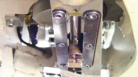
45 2.3. Needle Position Against Throat-Plate E - STANDARD MACHINE ADJUSTMENT Left-Right direction When the needle-bar bite is deactivated, the needle should go in the middle of the groove of the throat-plate. Use the gauge from the accessory. The needle-bar can be shifted using the screw marked in the picture below. THROAT-PLATE NEEDLE LEFT-RIGHT Front-Back direction Eventual misalignment shall be adjusted by shifting the machine head towards base. THROAT-PLATE NEEDLE FRONT-BACK 1-33


46 E - STANDARD MACHINE ADJUSTMENT 2.4. Needle-Bar Bite Clutch Timing Adjustment Release the cam 1 by loosing up the screws 2. (Keep the screws in, so that they still fit into the flats of the shaft). Rotate the hand-wheel until the mark on the cam and machine casting are aligned - refer to the picture. Remove the latch 3 by loosing up the screw 4. Then insert the stud 5 from the accessory. The cam 1 will be shifted in left-right direction to its proper position (marks shall stay aligned). Tighten the screws 2 now. 1-34


47 2.5. Needle-Bar Bite Timing E - STANDARD MACHINE ADJUSTMENT Keep the stud inserted in the clutch mechanism and adjust the needle-bar into the topmost position using the screw marked in the picture below Bigger Bottom Shaft Eccentric Keep the stud inserted in the clutch mechanism and adjust the position of the bigger bottom-shaft eccentric in the way that its slot is aligned with the line on the machine casting - refer to the picture. Remove the stud and reinstall the latch. 1-35


48 E - STANDARD MACHINE ADJUSTMENT 2.7. Needle-Bar Bite Clutch Switching Adjustment The latch shall be locked equally when the needle-bar bite is turned on and off respectively. x x 2.8. Needle-Bar Bite Width & Symmetry Needle-bar bite shall be 5.5 mm. This can be adjusted by the adjusting screw 1, after loosing up the nut 2. Use the gauge from the accessory. 1-36

49 E - STANDARD MACHINE ADJUSTMENT The bite should be symmetrically split from the centre needle-bar position, i.e., 2.75 mm to the left and 2.75 mm to the right. If this is not the case, readjust the position of the needle-bar bite cam refer to chapter Smaller Bottom Shaft Eccentric Auxiliary-Looper Timing This eccentric setting influences the position of the auxiliary-looper cam and thus its timing. This setting shall be performed for the left needle-bar bite any collision of the auxiliary-looper with the needle shall be avoided (refer to the pictures): when the needle is descending: the auxiliary-looper shall reach the left most position before the needle reaches the looper height when the needle is ascending: the auxiliary-looper shall not start its movement before the needle leaves the looper height The setting shall be performed by the screw of the smaller eccentric refer to the picture below. 1-37


50 2.10. Principal-Looper Timing & Position E - STANDARD MACHINE ADJUSTMENT The principal-looper timing shall be adjusted in the way that the needle does not touch the slot in the principal-looper during the left needle-bar bite refer to 1. The timing should be approximately 2.5 mm when the needle-bar bite is turned off. Use the screws 2. Principal-looper shall be located mm from the needle while the looper is catching the loop. Use the screw mm PRINCIPAL LOOPER NEEDLE The needle-eye top edge shall be located approx. 1 mm from the principal looper bottom edge. 1mm PRINCIPAL LOOPER NEEDLE Auxiliary-Looper Position In the front-back plane: the auxiliary-looper shall be placed so that the deepest point of its groove is in one line with the pike of the principal-looper refer to the picture on the left. Use the ring 4 to setup the looper axial position. In the left-right plane: when the auxiliary-looper is in the leftmost position, its distance from the needle shall be approx. 1mm for the left needle-bar bite refer to the picture on the left. Use the screw 5 only. AUXILIARY LOOPER 1mm NEEDLE 1-38

51 2.12. Sewing Servo-Motor Home Position E - STANDARD MACHINE ADJUSTMENT The home position of the sewing servo-motor is adjusted by the position of the ring refer to the picture. After establishing the servo-motor home position, the marks on the cam and machine casting should be aligned and the needle-bar just starting the right bite Opening Thread-Tension Cam The cam shall be adjusted so that its guideline is in the top position when the needle-bar is also in the topmost position refer to the picture. 1-39


52 3. HOME-POSITION RAW ADJUSTMENT 3.1. X-Axis Height E - STANDARD MACHINE ADJUSTMENT Adjust the height of X-axis mechanism using the marked screws to reach the clearance of 2.5 mm. 2.5 mm 3.2. Home Sensors Clearance All the home-position sensors (sewing servo-motor, X-axis, Y-axis, Y-differential-axis, and Z-axis) shall be adjusted according to the picture below, i.e., they should be located approx. 0.3 mm in the axial direction from their respective metal-shutters. After each adjustment press position. button to re-establish a home 3.3. X-Axis Home Position Use the X-axis home sensor / its shutter and the electronic correction to adjust the home position of X-axis (refer to the picture). Insert the gauge the needle shall go exactly into the centre hole in the left-right direction Bedplate X-Axis Position Using the screws marked in the picture, adjust the bedplate position into the depicted state. 1-40
 is being switched on/off. 3.6.")

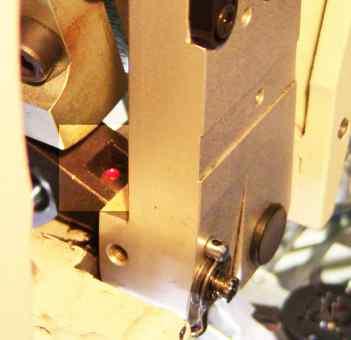
53 3.5. X-Axis Stop V -Shape Sewing Press E - STANDARD MACHINE ADJUSTMENT Adjust the X-axis stop left-right position (refer to the picture) in the way that the bedplate does not move when the X-axis stop cylinder (V9) is being switched on/off Y-Axis Home Position Use the Y-axis home sensor / its shutter and the electronic correction to adjust the home position of Y-axis (refer to the picture below). Insert the gauge the needle shall go exactly into the centre hole in the front-back direction Y-Differential-Axis Home Position Y-differential-axis establishes the position of the bedplate from the button. Use the Y-differential-axis home sensor / its shutter and the electronic correction to adjust the home position of Y-differential-axis (refer to the picture below). The needle shall be in one line with the pucker-pin edge refer to the picture below: 1-41
.")
54 3.8. Z-Axis Home Position E - STANDARD MACHINE ADJUSTMENT Use the Z-axis home sensor / its shutter and the electronic correction to adjust the home position of Y-differential-axis (refer to the picture below). In the home position, the button chuck should be 4 mm above the pucker-pin refer to the picture: 1-42

55 4. HOME-POSITION FINE ADJUSTMENT E - STANDARD MACHINE ADJUSTMENT 1. Press the home button. 2. Disable the main sewing servo: 3. Go to the X-Y-Z Movement Motors Adjustment Screen: 4. Insert this gauge into the machine chuck and press. 5. Use the hand-wheel to move the needle close to the gauge. 1-43

56 E - STANDARD MACHINE ADJUSTMENT 6. Use the following corrections to adjust the position in X and Y E 3.2). direction. Readjust the X-axis stop position in case of an X-direction correction change (refer to chapter 7. Remove the gauge using the button. 8. Use this correction to adjust the position of the pucker-pin Correct position is this:. 9. Use this correction to adjust the Z-axis (height of the chuck). Correct position is this:. 1-44
.")
. button from the main 4.")
57 E - STANDARD MACHINE ADJUSTMENT 5. AUXILIARY DEVICES 5.1. Thread Catcher Adjustment The thread catcher shall be adjusted in the following way: 1. To be as close to the machine head casting as possible. 2. In the horizontal direction: the thread catcher axis shall be in the same line with the needle (use needle 3 mm down). button from the main screen to bring the 3. In the vertical direction: to be 3 4 mm from the needle tip when the needle-bar is in the top position (use screen to bring the needle 3 mm down). button from the main 4. In its axial direction: it should be in the following position when the thread catcher is released (use button from the main screen to bring the needle 3 mm down). 12 mm 1-45


; descent the needle to be close the button gauge and adjust the button feeder position in the")
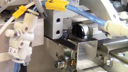
58 5.2. Button Feeder Adjustment The button feeder shall be adjusted in the way it feeds the flat 4-hole buttons properly: E - STANDARD MACHINE ADJUSTMENT 1. Vertical button feeder position: Disconnect the machine compressed-air supply and push the button feeder into the sewing area manually. There should be a clearance of approx. 1 mm between the button feeder and bedplate mechanisms refer to the following picture. Adjust this distance using the screws 1. 1 mm 2. Horizontal button feeder position: insert the button gauge onto the feeder and move the feeder to the sewing area (from Step-By-Step Button Feeding Screen); descent the needle to be close the button gauge and adjust the button feeder position in the way the centre hole of the gauge is right under the needle adjust the X-position (left & right) by the screws 2 attaching the button feeding mechanism to the main casting adjust the Y-position (front & back) by the screws 3 from the bottom of the feeding mechanism 5.3. Thread Rollers Position 26,5 mm (26) mm 42,5 mm 1-46
59 E - STANDARD MACHINE ADJUSTMENT 5.4. Thread Trimming Adjustment 1. Fixed Knife Adjustment FIXED KNIFE THROAT-PLATE 2. Moveable Knife Adjustment Adjustment in trimming position: FIXED KNIFE MOVEABLE KNIFE 1 mm 1-47

60 5.5. Thread Tail Blower E - STANDARD MACHINE ADJUSTMENT The thread tail blower must blow the thread tail from the beginning of the neck sewing in the way to be sewn into the button neck. 1. Activate the button turning step-by-step mode: 2. Insert the button and garment and start button sewing. 3. The machine will stop after button attaching stitching, press the foot-pedal three times. 4. Adjust the blowing tube horizontally and vertically according to the pictures; use the screws 1 : 1 5. Check the blower blows the thread tail properly so that it can be sewn in the button neck. Use the button 2 appeared now on the display to activate the blower
61 F - MACHINE MAINTENANCE WARNING! Check the condition of electric cables regularly! Make sure they are not damaged! Check that there are no damages on the safety covers. Change damaged covers for good ones or order them! Do not put fingers into the area of sewing needle or cutting mechanism under any circumstances! Do not modify the machine in any way that could limit safety components! CAUTION! Do not miss out doing regular maintenance. If there is power system breakdown, switch off the main power switch. Do not remove, modify or remove safety labels. Do not work on the machine intoxicated or impaired. Make sure that lighting equipment for the working area does not exceed 750 Lux. 1. Machine Cleaning and Maintenance CAUTION! Before you start the maintenance or cleaning, switch off the power supply and disconnect the air supply from the machine! 1.1. Daily Cleaning and Checking To ensure machine long life and reliability, it is important to apply below mentioned steps on daily bases after work shift Sewing mechanism cleaning Clean all moveable mechanism (linear guides, teeth-wheels and racks, bushings, etc.) using compressed air. 1-49
 Press drain valve 5 and drain condensation out 1. d) Disconnect air supply.")
62 F - MACHINE MAINTENANCE Filter unit cleaning and maintenance a) Connect the machine to the air supply. b) Check the level of condensation 1 in the reservoir 2. The liquid level must not get more than 10 mm under the filter sleeve 3. The height is marked by the lowest nut ferrel 4. c) Press drain valve 5 and drain condensation out 1. d) Disconnect air supply. In case of airflow decline, replace the filter sleeve 3. Filter sleeve must be changed after two years of machine operation at the latest or every time the pressure drops down to 0,1MPa. How to exchange filter sleeve: c) Push latch 6 in the direction of the arrow and turn reservoir 2 of 45 any side you like. d) Pull reservoir 2 out in the direction of the arrow. e) Loosen nut 4 by turning it counter-clockwise. f) Remove filter sleeve 3 and put new one. g) Put filter together. ± Needle check a) Loosen screw 1 and take needle out 2. b) Check that needle tip is not damaged c) Roll the needle on the flat board to see whether the needle is not bent d) Replace the needle with a new one if damaged or bent! e) After checking put the needle 2 back into machine see chapter C
63 F - MACHINE MAINTENANCE 1.2. Cleaning and Checking as Needed Apply instructions bellow as needed with regard to machine production workload Control box Use vacuum cleaner to clean control box 1 filter sleeves 2. 1 PHASE V 50/60 Hz Draining lubrication oil out Check the oil tank 1 under the machine. If it is full, remove the tank by turning it clockwise and empty it out. Put the tank back onto its place. NOTE! Disposal of the used oil must correspond with ecological standards! Eye safety cover Clean the eye safety covers 1 with wet cloth. NOTE! Do not use any aggressive cleaning solutions, i.e. paraffin oil, etc.! They may create color stains on the safety cover and cause bad transparence. 1-51
 If the display shows the error message in service menu - see chapter E, it is necessary to check the battery connection, or to replace the battery.")
64 F - MACHINE MAINTENANCE Battery replacement a) If the display shows the error message in service menu - see chapter E, it is necessary to check the battery connection, or to replace the battery. b) Battery lifetime is guaranteed for 5 years at the temperature of 25 C. Higher temperatures significantly reduce the lifetime of the battery (at 55 C it is only 1.5 years). c) In order not to lose data, it is important to replace battery within 5 days from the first indication. This period can be prolonged if the machine stays switched on. When replacing the battery, make sure you do the following: a) Never shorten the connector from the battery in the PLC. Never charge the battery. Never break the battery. All these may cause the battery loses its lifetime, it may set fire or damage the battery cover and fail the guarantee. b) Never use a battery that fell down or got hit in another way. Replace the battery only when the power supply is disconnected. When the battery is disconnected, the data keep saved for 5 minutes. After this period the data may get lost. The battery can be replaced by an instructed mechanic only. If the machine is not in operation for longer time, the lifetime of the battery shortens. Note! The error message showed on the display will be automatically deleted when a new battery is placed in. 1-52

65 F - MACHINE MAINTENANCE 2. Maintenance List Once a day 10 hours Maintenance list Clean sewing mechanism area Clean frame area Check cutting knife edge Check level of condensate in regulator filter Once a week 80 hours Lubricate the places from chapter F 2.1. Once a month 300 hours Check sewing mechanism drive play Check filth in filter sleeves in control box Check tank and waste oil Lubricate the places from chapter F 2.2. Check screw joints tightness (keep values below) Recommended values for screws freeze (Nm) M3 0,5 0,6 0,8 M4 1,2 1,5 2,0 M5 2,5 3,0 4,0 M6 4,0 5,0 7,0 M8 8,0 16,0 M10 10,0 30, Places to be Lubricated by Oil Weekly Use mineral oil to avoid garment to get dirty. Fill the reservoir up to half level only to avoid oil flow out when the machine is tilted. 1-53


66 F - MACHINE MAINTENANCE 1-54


67 F - MACHINE MAINTENANCE 1-55


68 F - MACHINE MAINTENANCE 1-56


69 F - MACHINE MAINTENANCE 1-57


70 F - MACHINE MAINTENANCE This ball-screw shall be lubricated with a lubricant which does NOT contain MoS2 or graphite. Either oil or grease can be used: we recommend oils of class CL in accordance with DIN 51517, part 2 we recommend grease based on mineral oil, class K2K, DIN 51825; greasing should occur after each running hours The linear guides shall be lubricated with lithium type grease. When dusts are adhered on the surface during operations, wash it with clean white kerosene and re-lubricate. Greasing should occur after each running hours. 1-58


71 F - MACHINE MAINTENANCE 2.2. Places to be Lubricated by Grease Monthly 1-59


72 F - MACHINE MAINTENANCE 1-60
MODEL S-211 ELECTRONIC EYELET BUTTONHOLE MACHINE PARTS AND SERVICE MANUAL PART NUMBER MACHINE SERIAL No.
 MODEL ELECTRONIC EYELET BUTTONHOLE MACHINE PARTS AND SERVICE MANUAL MACHINE SERIAL No. PART NUMBER 97. 1990.0.001 This manual is valid from the machine serial No.: G190137 AMF is trademark of AMF Group,
MODEL EBS Mark II ELETRONIC BUTTON STITCHER MACHINE PARTS AND SERVICE MANUAL PART NUMBER MACHINE SERIAL No:
 MODEL EBS Mark II ELETRONIC BUTTON STITCHER MACHINE PARTS AND SERVICE MANUAL MACHINE SERIAL No: PART NUMBER 97.7100.0.000 This manual is valid from the machine Serial No.: L710004 AMF je obchodní značka
MODEL DECO 2000 DECORATIVE STITCHING MACHINE PARTS AND SERVICE MANUAL PART NUMBER MACHINE SERIAL No:
 MODEL DECORATIVE STITCHING MACHINE PARTS AND SERVICE MANUAL MACHINE SERIAL No: PART NUMBER 97.7000.0.003 This manual is valid from the machine Serial No.: P704697 03 / 2018 MODEL DECORATIVE STITCHING
MODEL S-4000 ISBH+I SM
 MODEL S-4000 ISBH+I SM ELECTRONIC BUTTONHOLE MACHINE PARTS AND SERVICE MANUAL MACHINE SERIAL No: PART NUMBER 97.2486.3.001 This manual is valid from the machine Serial No.: R241683 09 / 2015 LIMITED WARRANTY
MODEL S-311+I OPERATING INSTRUCTIONS S-311+I
 MODEL S-311+I OPERATING INSTRUCTIONS TABLE OF CONTENTS A - INTRODUCTION... 1. GENERAL INFORMATION... 2. SAFETY LABELS AND EQUIPMENT DEVICE... 3. SPECIFICATIONS... B - MACHINE ASSEMBLY... S-311+I AF -
Omron MODEL S-4000 TKF, LS TACKER AND LABEL SEWER PARTS AND SERVICE MANUAL
 MODEL S-4000 TKF, LS Omron TACKER AND LABEL SEWER PARTS AND SERVICE MANUAL MACHINE SERIAL No.: PART NUMBER 97.2441.1.001 This manual is valid from the machine serial number M241428 AMF is trademark of
MODEL S-4000 ISBH Omron
 MODEL S-4000 ISBH Omron STRAIGHT BUTTONHOLE MACHINE FOR IMITATION SLEEVE BUTTONHOLES PARTS AND SERVICE MANUAL MACHINE SERIAL No.: PART NUMBER 97.2433.1.001 This manual is valid from the machine serial
IMPORTANT SAFETY INSTRUCTIONS
 CONTENTS 1.SPECIFICATIONS... 1 2.INSTALLATION... 1 3.INSTALLATION OF THE SYNCHRONIZER... 2 4.ASSEMBLY OF HAND WHEEL... 2 5.INSTALLATION OF HAND WHEEL... 2 6.INSTALLING THE BELT COVER... 3 7.ADJUSTING THE
BL Series INSTRUCTIONS
 BL Series Models: EX5204/BL514 EX5204/BL515 EX5214/BL524 EX5214/BL525 EXT5214/BL524 EXT5214/BL525 EX5404/BL614 EX5404/BL615 EX5414/BL624 EX5414/BL625 EXT5214H/BL528 EXT5214H/BL529 Automatic Backlatcher
/11, -14/31 INSTRUCTION MANUAL. This instruction manual applies to machines from the following serial numbers onwards: #
 3834-4/, -4/3 INSTRUCTION MANUAL This instruction manual applies to machines from the following serial numbers onwards: # 2 733 53 296-2-8 936/002 Betriebsanleitung engl. 06.09 This Instruction manual
MB-1800 Series INSTRUCTION MANUAL
 MB-800 Series INSTRUCTION MANUAL CONTENTS!. SPECIFICATIONS... @. NAME OF EACH COMPONENT.... Name of the main unit... #. INSTALLATION... $. PREPARATION OF THE SEWING MACHINE...7. Attaching the needle...
MODEL XL-21 EYELET BUTTONHOLE MACHINE PARTS AND SERVICE MANUAL PART NUMBER MACHINE SERIAL No.
 MODEL XL-21 EYELET BUTTONHOLE MACHINE PARTS AND SERVICE MANUAL MACHINE SERIAL No. AMF is trademark of AMF Group, Inc. PART NUMBER 97. 1800.2.002 This manual is valid from the machine serial No.: F180291
Industrial Sewing Machine TECHNICAL MANUAL SEWING MACHINE HEAD. Electronic Pattern Sewing Machine. Model PLK-G1010 A180E593P03
 Industrial Sewing Machine TECHNICAL MANUAL SEWING MACHINE HEAD Electronic Pattern Sewing Machine Model PLK-G1010 A180E593P03 FOR SAFE USE Before the installation, operation, and inspection for this product,
RH-981A ENGLISH ELECTRONIC EYELET BUTTON HOLER
 ENGLISH ELECTRONIC EYELET BUTTON HOLER Thank you very much for buying a BROTHER sewing machine. Before using your new machine, please read the safety instructions below and the explanations given in the
DA-9270 TWIN NEEDLE (THREE NEEDLE) FEED OFF THE ARM DOUBLE CHAIN STITCHER. English
 FEED OFF THE ARM DOUBLE CHAIN STITCHER. English") TWIN NEEDLE (THREE NEEDLE) FEED OFF THE ARM DOUBLE CHAIN STITCHER English Thank you very much for buying a BROTHER sewing machine. Before using your new machine, please read the safety instructions below
TWIN NEEDLE (THREE NEEDLE) FEED OFF THE ARM DOUBLE CHAIN STITCHER English Thank you very much for buying a BROTHER sewing machine. Before using your new machine, please read the safety instructions below
Please read this manual before using the machine. Please keep this manual within easy reach for quick reference.
 DA-927A DA-928A INSTRUCTION MANUAL Please read this manual before using the machine. Please keep this manual within easy reach for quick reference. TWIN NEEDLE / THREE NEEDLE FEED OFF THE ARM DOUBLE CHAIN
Industrial Sewing Machine TECHNICAL MANUAL SEWING MACHINE HEAD. Electronic Pattern Sewing Machine. Model PLK-G2516 A180E621P01
 Industrial Sewing Machine TECHNICAL MANUAL SEWING MACHINE HEAD Electronic Pattern Sewing Machine Model PLK-G2516 A180E621P01 FOR SAFE USE Before the installation, operation, and inspection for this product,
Industrial Sewing Machine TECHICAL MANUAL SEWING MACHINE HEAD. Electronic Pattern Sewing Machine. Model PLK-G1010 A180E593P02
 Industrial Sewing Machine TECHICAL MANUAL SEWING MACHINE HEAD Electronic Pattern Sewing Machine Model PLK-G1010 A180E593P02 FOR SAFE USE Before the installation, operation, and inspection for this product,
Part 2: Installation Instructions cl
 Contents Page: Part 2: Installation Instructions cl. 381-382 1. Delivery scope............................... 3 2. General and Transportation safety precautions........... 3 3. Stand installation 3.1 Installing
Please read this manual before using the machine. Please keep this manual within easy reach for quick reference.
 INSTRUCTION MANUAL Please read this manual before using the machine. Please keep this manual within easy reach for quick reference. HIGH SPEED SINGLE NEEDLE STRAIGHT LOCK STITCHER Thank you very much for
PLC-1700 Series PLC-1710, , 1760, , 1760L
 Post-bed, Unison-feed, Lockstitch Machine PLC-1700 Series PLC-1710, 1710-7, 1760, 1760-7, 1760L ENGINEER S MANUAL 40040656 No.E372-00 Introduction This Engineer s Manual is for technical service engineers.
ENGINEER S MANUAL No.01
 1-NEEDLE, UNISON FEED, LOCKSTITCH MACHINE (AUTOMATIC LUBRICATION) LU-1510 1-NEEDLE, UNISON FEED, LOCKSTITCH MACHINE WITH AUTOMATIC THREAD TRIMMER (AUTOMATIC LUBRICATION) LU-1510-7 1-NEEDLE, UNISON FEED,
Model PLK-G5050 PLK-G10050
 Industrial Sewing Machine TECHNICAL MANUAL SEWING MACHINE HEAD Electronic Pattern Sewing Machine Model PLK-G5050 PLK-G10050 A180E686P01 FOR SAFE USE Before the installation, operation, and inspection for
USER S MANUAL. SS-7350 Series. Small cylinder bed interlock sewing machine
 R USERS MANUAL SS-7350 Series Small cylinder bed interlock sewing machine R Best Quality Best Price Best Service 1. Thank you for purchasing our product. Based on the rich expertise and experience accumulated
Please read this manual before using the machine. Please keep this manual within easy reach for quick reference.
 INSTRUCTION MANUAL Please read this manual before using the machine. Please keep this manual within easy reach for quick reference. SINGLE NEEDLE DIRECT DRIVE STRAIGHT LOCK STITCHER WITH THREAD TRIMMER
EHA Hoffmann International GmbH
 EHA Hoffmann International GmbH User manual EHA-TRANSPRINT HP 2020 Machine-No.: Year: EHA Hoffmann International GmbH Michelsbergstraße 24 D-57080 Siegen/Germany Telephone: +49 271 39 32-0 Telefax: +49
Technical Data. Name: ERIKA Automat fully automatic machine to divide and to round dough pieces of the same size
 AUTOMAT MANUAL 1 Technical Data Name: ERIKA Automat fully automatic machine to divide and to round dough pieces of the same size Type Divisions Dough Portions (in ounces) Plate Nos. 3 30 1.0 3.5 #35 4/40A
Industrial Sewing Machine TECHNICAL MANUAL MECHANICAL VERSION. Electronic Pattern Sewing Machine. Model PLK-E2010R A180E530P01
 Industrial Sewing Machine TECHNICAL MANUAL MECHANICAL VERSION Electronic Pattern Sewing Machine Model PLK-E2010R A180E530P01 FOR YOUR SAFETY! If you are operating the sewing machine for first time, please
HEDMAN The HEDMAN Company 189 Gordon St. Elk Grove Village, IL
 HEDMAN The HEDMAN Company 189 Gordon St. Elk Grove Village, IL 60007 800-872-2788 NOTICE Proprietary Information - this material is not to be reproduced by any means or disclosed in any way without prior
GENIUS 14 GENIUS 18 OPERATING & MAINTENANCE
 GENIUS 14 GENIUS 18 INTRODUCTION OPERATING & MAINTENANCE INSTRUCTIONS This operator s book has important information for the use and safe operation of this machine. Read this book carefully before starting
Please read this manual before using the machine. Please keep this manual within easy reach for quick reference.
 INSTRUCTION MANUAL Please read this manual before using the machine. Please keep this manual within easy reach for quick reference. SINGLE NEEDLE DIRECT DRIVE LOCK STITCHER WITH ELECTRONIC FEEDING SYSTEM
Products documentation (REVISION DATE: 03/10/2011) OMFP6010 (60cm PIROLITIC OVEN)
 OMFP6010 (60cm PIROLITIC OVEN)") Products documentation (REVISION DATE: 03/10/2011) OMFP6010 (60cm PIROLITIC OVEN) Ovens Service Manual Models OMFP6010 CONTENTS This document has been published to be used for service only. The contents
Products documentation (REVISION DATE: 03/10/2011) OMFP6010 (60cm PIROLITIC OVEN) Ovens Service Manual Models OMFP6010 CONTENTS This document has been published to be used for service only. The contents
Altra Series Dampener
 Crestline TM Altra Series Dampener Installation Instructions Heidelberg MO X88-66 10/97 Rev-A GENERAL INFORMATION ATTENTION CRESTLINE ALTRA SERIES TM DAMPENER OWNER! Accel Graphic Systems provides parts
Ultra Lightweight Household & Commercial Vacuums
 Owner s Manual Ultra Lightweight Household & Commercial Vacuums Save These Instructions Index Important Safety Instructions............................................................. 2 Polarization Instructions................................................................
PS-2/ES Automated pack & tag machine with IndES fastening system
 English Manual PS-2/ES Automated pack & tag machine with IndES fastening system Contents 1. Introduction 2. Important Safety Instructions 3. PS-2/ES 4. Unpacking the machine 5. Setting up the machine 6
OPERATING MANUAL Gfp 255C Please read this manual carefully before operating!
 OPERATING MANUAL Gfp 255C Please read this manual carefully before operating! Unpacking, assembly, and operating videos are available at www.gfpsmoothstart.com 1 Table of Contents Gfp 255C March 2015 Contents
AK-154 INSTRUCTION MANUAL
 AK-154 INSTRUCTION MANUAL 1 CONTENTS 1. FEATURES... 1 2. INSTALLATION... 2 3. HOW TO SELECT THE FUNCTION OF AUTO-LIFTER... 5 4. OTHERS (Advanced edition)... 6 4-1. Function for reducing the presser foot
TACH-IT MODEL #3568 SEMI-AUTOMATIC TWIST TIE MACHINE OPERATION MANUAL AND PARTS LIST
 TACH-IT MODEL #3568 SEMI-AUTOMATIC TWIST TIE MACHINE OPERATION MANUAL AND PARTS LIST 1 TABLE OF CONTENTS: SECTION 1 CAUTION PAGE 3 SECTION 2 PARTS IDENTIFICATION PAGE 4 SECTION 3 MACHINE DIMENSIONS AND
SEWING MACHINE 45 / 21 STITCH
 SEWING MACHINE 45 / 21 STITCH 90715 ASSEMBLY AND OPERATING INSTRUCTIONS 3491 MISSION OAKS BLVD., CAMARILLO, CA 93011 VISIT OUR WEB SITE AT HTTP://WWW.HARBORFREIGHT.COM Copyright 2003 by Harbor Freight
Instruction Manual and Parts List. Ultra High Speed Overedge and Safety Stitch Machine
 Instruction Manual and Parts List Ultra High Speed Overedge and Safety Stitch Machine 32D 3M-04 3M-04 / KS 32M-05 34M-04 24M-24 24M-24 / KS 244M-24 25M-35 25M-35 / KH 25M-55 25M-55 / KH 25M-56 25H-56 /
Owner's Manual Paramount 65X GRAPHIC LAMINATION PRODUCTS
 Owner's Manual Paramount 65X GRAPHIC LAMINATION PRODUCTS Royal Sovereign International Inc. Please read and retain these instructions. To register your product, please go to www.royalsovereign.com www.royalsovereign.com
MSK-8900M Industrial Sewing Machine. Instruction Manual
 MSK-8900M Industrial Sewing Machine Instruction Manual CONTENTS Operation instruction. Brief introduction. Main specifications. Main parts name 4. The method of installation 5 5. Pareparation before sewing
OPERATING & SERVICE PARTS MANUAL HDS-215 COMBINATION SHRINK SYSTEM
 OPERATING & SERVICE PARTS MANUAL HDS-215 COMBINATION SHRINK SYSTEM FOR HOT KNIFE AND IMPULSE MACHINES READ ALL INSTRUCTIONS CAREFULLY BEFORE OPERATING EQUIPMENT TABLE OF CONTENTS Electrical Requirements
52 STRATHMERE CEILING FAN
 52 STRATHMERE CEILING FAN Owner s Manual Models #20341 If a problem cannot be remedied or you are experiencing difficulty with installation, please contact the Service Department: 1-877-459-3267, 9 a.m.-
OPERATOR S MANUAL. For BURLY ATTACHMENTS
 OPERATOR S MANUAL For BURLY ATTACHMENTS April 4, 2018 Clod-Buster Topsoil Screener LIMITED WARRANTY Burly Attachments, LLC warrants to the original Purchaser, all products, manufactured by it, to be free
Part 3: Service manual, class
 Contents Page: Part : Service manual, class 7-75. General.................................................. Gauges................................................. 4. Description and adjustment of the
EAGLE 2000B EAGLE 2000BE EAGLE 2000EBT MUST READ MANUAL PRIOR TO INSTALLING MACHINE
 EAGLE 2000B EAGLE 2000BE EAGLE 2000EBT MUST READ MANUAL PRIOR TO INSTALLING MACHINE Contents 1 Machine Safety Information 3 1.5 Safety Precautions Prior to Operating Machine 6 2 Machine Installation 7
BAS-300G-484 BAS-300G-484 SF
 BAS-300G-484 BAS-300G-484 SF DIRECT DRIVE PROGRAMMABLE ELECTRONIC PATTERN SEWER Please read this manual before using the machine. Please keep this manual within easy reach for quick reference.
BQ-260/260L. Important Information BOOK BINDER
 BOOK BINDER BQ-260/260L Important Information - This manual is designed to help you to install, operate and maintain Perfect Binder BQ- 260/260L. Read, understand and keep this manual in a safe and convenient
Important Information
 BQ-270 PERFECT BINDER Important Information This manual is designed to help you to install, operate and maintain the BQ-270 Perfect Binder. Please read and understand this manual, and keep it in a safe
BARRACUDA 200ZW PORTABLE WALKING FOOT SEWING MACHINE INSTRUCTION MANUAL
 BARRACUDA 00ZW PORTABLE WALKING FOOT SEWING MACHINE INSTRUCTION MANUAL THE BARRACUDA 00ZW PORTABLE WALKING FOOT SEWING MACHINE INSTRUCTION MANUAL MATERIAL IS OWNED BY RELIABLE AND MAY NOT BE REPRODUCED
48 TAYLOR CEILING FAN
 48 TAYLOR CEILING FAN Owner s Manual Models #20554 If a problem cannot be remedied or you are experiencing difficulty in installation, please contact the Service Department: 1-877-459-3267, 9 a.m.- 5 p.m.
USER S MANUAL. KM-1060BL Series KM-1060BL KM-1060BL-7 KM-1062BL KM-1062BL-7
 USER S MANUAL KM-1060BL Series KM-1060BL KM-1060BL-7 KM-1062BL KM-1062BL-7 R Best Quality Best Price Best Service 1. Thank you for purchasing our product. Based on the rich expertise and experience accumulated
Thank you for purchasing Pegasus automatic unit.
 HG Series odels: HG-110/W664-08 HG-130/WT664-08 HG-140/WT664-35 Thank you for purchasing Pegasus automatic unit. Study this manual very carefully before beginning any of the procedure and then use the
52 SAN LUCAS CEILING FAN
 52 SAN LUCAS CEILING FAN Owner s Manual Models #20551 If a problem cannot be remedied or you are experiencing difficulty in installation, please contact the Service Department: 1-877-459-3267, 9 a.m.-
CONTENTS 1. SPECIFICATIONS SET-UP FOR THE OPERATOR MAINTENANCE... 34
 ENGLISH ii CONTENTS. SPECIFICATIONS... 2. SET-UP.... Installing the motor unit... 2. Installing the control box... 3. Installing the belt... 2 4. Adjusting the pulley cover... 2 5. Installation and adjustment
AMS-224EN6060 / IP-420 INSTRUCTION MANUAL
 AMS-224EN6060 / IP-420 INSTRUCTION MANUAL * This Instruction Manual only describes the functions which are different from those of the AMS-224EN/IP-420. In order to use the AMS-224EN6060 safely, please
Auto Opening with Pressure Readout 15 x15 & 16 x20 Heat Transfer Machines
 S-450P & S-650P Auto Opening with Pressure Readout 15 x15 & 16 x20 Heat Transfer Machines OWNER S MANUAL S-650P shown For Customer Service, Call 1-800-835-0606 or Visit www.hixcorp.com CONTENTS Receiving
Please read this manual before using the machine. Please keep this manual within easy reach for quick reference.
 INSTRUCTION MANUAL Please read this manual before using the machine. Please keep this manual within easy reach for quick reference. SINGLE NEEDLE DIRECT DRIVE LOCK STITCHER WITH ELECTRONIC FEEDING SYSTEM
KE-430HX KE-430HS BE-438HX
 KE-430HX KE-430HS BE-438HX INSTRUCTION MANUAL Please read this manual before using the machine. Please keep this manual within easy reach for quick reference. ELECTRONIC DIRECT DRIVE LOCKSTITCH BAR TACKER
/ /020 INSTRUCTION MANUAL
 3588-05/020-15/020 INSTRUCTION MANUAL This instruction manual applies to machines from serial number 2 760 129 and software version 0380/003, 0381/003 onwards 296-12-19 094/002 Betriebsanleitung engl.
Torrena 42 Ceiling Fan
 Torrena 42 Ceiling Fan Owner s Manual Part # 269268, 269269 Model # 32096, 32097 Exclusively Distributed by: HD Supply Facilities Maintenance, Ltd. Atlanta, GA 30339 2017 Made in China If you are experiencing
MIXERS SMX10-1, SMX20-1, SMX20-2, SMX30-1 INSTRUCTION MANUAL
 SMX10-1, SMX20-1, SMX20-2, SMX30-1 MIXERS This manual contains important information regarding your Supera unit. Please read this manual thoroughly prior to equipment set-up, operation and maintenance.
MITSUBISHI. Industrial Sewing Machine. Model PLK-E1010 TECHNICAL MANUAL MECHANICAL VERSION. Electronic Pattern Sewing Machine A180E494P01
 MITSUBISHI Industrial Sewing Machine TECHNICAL MANUAL MECHANICAL VERSION Electronic Pattern Sewing Machine Model PLK-E00 A80E9P0 FOR YOUR SAFETY! If you operate the sewing machine first time, please make
WET/DRY VACUUM. QUEST for Continuous Improvement Windsor s Quality Management System is Certified ISO MODEL: T1. Operating Instructions (ENG)
") WET/DRY VACUUM Operating Instructions (ENG) MODEL: T1 y QUEST for Continuous Improvement Windsor s Quality Management System is Certified ISO 9001. Read these instructions before operating the machine.
WET/DRY VACUUM Operating Instructions (ENG) MODEL: T1 y QUEST for Continuous Improvement Windsor s Quality Management System is Certified ISO 9001. Read these instructions before operating the machine.
INSTRUCTION MANUAL. This instruction manual applies to machines from the following serial numbers onwards: #
 245 246 INSTRUCTION MANUAL This instruction manual applies to machines from the following serial numbers onwards: # 6 500 24 296-2-9 99/002 Betriebsanleitung engl. 05.2 This Instruction Manual is valid
Camarillo 52 Ceiling Fan
 Owner s Manual Camarillo 52 Ceiling Fan Part # 269263, 269259, 269287 Model # 32091, 32092, 32087 Exclusively Distributed by: HD Supply Facilities Maintenance, Ltd. Atlanta, GA 30339 2017 Made in China
USER S MANUAL. SPS/E-1507 Series. Electronically Controlled Pattern Sewing Machine (Mechanical Part)
") R USERS MANUAL SPS/E-1507 Series Electronically Controlled Pattern Sewing Machine (Mechanical Part) R Best Quality Best Price Best Service 1. Thank you for purchasing our product. Based on the rich expertise
R USERS MANUAL SPS/E-1507 Series Electronically Controlled Pattern Sewing Machine (Mechanical Part) R Best Quality Best Price Best Service 1. Thank you for purchasing our product. Based on the rich expertise
LK-1903B/BR35 INSTRUCTION MANUAL
 LK-1903B/BR35 INSTRUCTION MANUAL CONTENTS I. SPECIFICATIONS...1 1. Specifications... 1 2. Model classification according to the button size... 2 3. Shape of buttons... 2 II. NAME OF EACH COMPONENT...3
CBT LW MAINTENANCE GUIDE
 CBT LW MAINTENANCE GUIDE PICTOGRAMS Each Signifier displayed here is specific to this User Manual. Menu Previous Advance Note Tip Example Powder Feeder Mixing Bowl Weigh Scale CBP Tanks Control Panel PSD
DOCUMENT CREASING MACHINE
 DOCUMENT CREASING MACHINE OPERATORS MANUAL Morgana Systems Limited Snowdon Drive Winterhill Milton Keynes Buckinghamshire MK6 1AP United Kingdom Telephone: ( 01908 ) 608888 Facsimile: ( 01908 ) 692399
Operating Manual. Combination Table Sealing Press. Series: Classic. CiMa-Pak Corporation Montreal Toronto New York. Telephone:
 Operating Manual Combination Table Sealing Press Series: Classic CiMa-Pak Corporation Montreal Toronto New York Telephone: 1-877-631-2462 Translation This operating manual has been translated from the
Instruction Manual. Nacho Cheese Dispenser and Warmer
 Instruction Manual Nacho Cheese Dispenser and Warmer 10700 Medallion Drive, Cincinnati, Ohio 45241-4807 USA 2013 Gold Medal Products Co. Part No. 36060 SAFETY PRECAUTIONS Page 2 INSTALLATION INSTRUCTIONS
Please read this manual before using the machine. Please keep this manual within easy reach for quick reference.
 INSTRUCTION MANUAL Please read this manual before using the machine. Please keep this manual within easy reach for quick reference. ELECTRONIC DIRECT DRIVE LOCKSTITCH BUTTON HOLER Thank you very much for
INTELLI-VAC 14 INTELLI-VAC 18
 INTELLI-VAC 14 INTELLI-VAC 18 INTRODUCTION OPERATING & MAINTENANCE INSTRUCTIONS This operator s book has important information for the use and safe operation of this machine. Read this book carefully before
CUTMASTER Strip Cutting Machine
 EASTMAN THE EASTMAN CUTMASTER Strip Cutting Machine WARNING Safety glasses must be worn at all times when operating or servicing this equipment. Instruction Manual & Illustrated Parts List Please read
KE-430D BE-438D ELECTRONIC DIRECT DRIVE LOCKSTITCH BAR TACKER ELECTRONIC DIRECT DRIVE LOCKSTITCH BUTTON SEWER
 KE-430D ELECTRONIC DIRECT DRIVE LOCKSTITCH BAR TACKER BE-438D ELECTRONIC DIRECT DRIVE LOCKSTITCH BUTTON SEWER Thank you very much for buying a BROTHER sewing machine. Before using your new machine, please
52 BERKSHIRE CEILING FAN
 52 BERKSHIRE CEILING FAN Owner s Manual Models #20223, 20224 If a problem cannot be remedied or you are experiencing difficulty in installation, please contact the Service Department: 1-877-459-3267, 9
AC6 & AC8 HORIZONTAL SERIES Sealed Metallic Centrifugal Pumps Installation and Maintenance Instructions
 AC6 & AC8 HORIZONTAL SERIES Sealed Metallic Centrifugal Pumps Installation and Maintenance Instructions ASSEMBLY PUMPS WITH MOTORS 1. No assembly required. Unpack the pump and motor and examine for any
TB-390 Conveyor Stacker
 TB-390 Conveyor Stacker OPERATIONS MANUAL Revised: 7-30-14 RENA Systems Inc. would like to Thank You for investing in our quality built products. Please record the following information for future reference:
(3 plastic wire connectors,blade balancing kit, 2 extra mounting screws #10-32 for outlet box.)
") Excel Lighting & Manufacturing Ltd. Lifetime Limited Warranty Excel Lighting & Manufacturing Ltd. Warrants the fan motor to be free from defects in workmanship and material present at time of shipment
Excel Lighting & Manufacturing Ltd. Lifetime Limited Warranty Excel Lighting & Manufacturing Ltd. Warrants the fan motor to be free from defects in workmanship and material present at time of shipment
Installation and Operating Instructions DÜRR Regeneration Unit for X-ray developers XR 24, XR24 II, XR 24 Nova, XR 24 Pro
 Installation and Operating Instructions DÜRR Regeneration Unit for X-ray developers XR 24, XR24 II, XR 24 Nova, XR 24 Pro 2006/01 Content Important Information 1. Notes... 3 1.1 CE - Labeling... 3 1.2
Gfp 400 Series August Gfp 463 TH. Please read this manual carefully before operating!
 OPERATING MANUAL Gfp 455 TH Gfp 463 TH Please read this manual carefully before operating! 1 Table of Contents Gfp 400 Series August 2015 Contents Page 1. Introduction 3 2. Important Safety Instructions..
User s Manual and Warranty Information for Counterweighted Chain Drive ThyssenKrupp Access
 II User s Manual and Warranty Information for Counterweighted Chain Drive ThyssenKrupp Access Part #2139703 Rev. G II Table of Contents Introduction...3 Elevator Overview...4 Description of Features...5-7
Grafisk Maskinfabrik A/S Bregnerødvej 92, DK-3460 Birkerød, Denmark. Website: Phone:
 IR330 Inspection Rewinder with Label Dispenser & Inkjet IR330 Operation Manual Grafisk Maskinfabrik A/S Bregnerødvej 92, DK-3460 Birkerød, Denmark. Website: www.gm.dk. E-Mail: gm@gm.dk. Phone: +45 4581
52 BAYTOWNE CEILING FAN
 52 BAYTOWNE CEILING FAN Owner s Manual Models #20501 If a problem cannot be remedied or you are experiencing difficulty in installation, please contact the Service Department: 1-877-459-3267, 9 a.m.- 5
52 CEILING FAN. Owner s Manual Models #50336, 50337
 52 CEILING FAN Owner s Manual Models #50336, 50337 If a problem cannot be remedied or you are experiencing difficulty in installation, please contact the Service Department: 1-877-706-3267, 9 a.m.- 5 p.m.
SC-922 InStruCtIon Manual
 SC-922 Instruction Manual CONTENTS I. SPECIFICATIONS... 1 II. SET-UP... 1 1. Installing to the table...1 2. Installing the motor unit...2 3. Installing the control box...2 4. Installing the belt...3 5.
Please read operating instructions carefully before use and keep it for further reference.
 GB OPERATING INSTRUCTIONS Automatic hot-air welding machine Please read operating instructions carefully before use and keep it for further reference. APPLICATION Overlap and tape welding of coated fabric
INSTALLATION, OPERATION, AND MAINTENANCE MANUAL
 INSTALLATION, OPERATION, AND MAINTENANCE MANUAL TUBE AXIAL FANS BTA, WTA, HTA, DDA The purpose of this manual is to aid in the proper installation and operation of the fans. These instructions are intended
User s Manual and Operating Instructions
 User s Manual and Operating Instructions Model Numbers: PT-18W-DDF-A, PT-20F-DDF-A, PT-20S-DDF, PT-24O-DDF, PT-24-DDF, PT-24-DDF-F, PT-30-DDF, PT-30P-DDF-A, PT-30P-DDF-AF READ AND SAVE THESE INSTRUCTIONS
OPERATING INSTRUCTIONS
 OPERATING INSTRUCTIONS FOR CARPET PRO UPRIGHT VACUUMS MODELS : CPU-75, CPU-75T, CPU-85, CPU-85T Before operating the vacuum, please read these instructions completely. Index Important Safety Instructions.............................................................2
52 BARSTOW CEILING FAN
 52 BARSTOW CEILING FAN Owner s Manual Models #20519 If a problem cannot be remedied or you are experiencing difficulty with installation, please contact the Service Department: 1-877-459-3267, 9 a.m.-
STEAM WALLPAPER STRIPPER MODEL HTW5
 STEAM WALLPAPER STRIPPER MODEL HTW5 From Serial Number 75154 (110 Volt North America only) OWNERS MANUAL & OPERATING INSTRUCTIONS 2016/11 Hiretech Part # 007717 WARNING For safe operation of this machine,
OWNERS MANUAL FOR MEC 300E ATA
 OWNERS MANUAL FOR MEC 300E ATA PLEASE READ AND FULLY UNDERSTAND THE INSTRUCTIONS PRIOR TO SETTING OR TUNING THE MACHINE. CAUTION: ANY MEC CLAY TARGET MACHINE MUST BE IN THE DISARMED STATE WITH THE BATTERY
User s Manual: WERI Mini Applicator
 User s Manual: User s Manual Page 1 of 15 Table of Content 1 Document revision history... 2 2 Important warnings... 3 3 Symbols... 4 4 Identification... 5 5 Technical data... 5 6 Installation (trained
DDL-900BB INSTRUCTION MANUAL
 DDL-900BB INSTRUCTION MANUAL CONTENTS I. SPECIFICATIONS... 1 II. SET-UP... 3 1. Installation...3 2. Installing the pedal sensor...4 3. Installing the power switch (for CE)...5 4. Connecting the connector...6
OWNER'S MANUAL RSL MyBinding.com 5500 NE Moore Court Hillsboro, OR Toll Free: Local:
 OWNER'S MANUAL RSL-2701 Read all instructions carefully before use. For any Customer Support needs please choose the Customer Support tab on www.royalsovereign.com topic TABLE OF CONTENTS page 1. Introduction...
Model UVGMD-AL MULTIVERSA CAN PACKAGING MACHINE Operators Manual
 Model UVGMD-AL MULTIVERSA CAN PACKAGING MACHINE Operators Manual MODEL UVGMD-AL INTRODUCTION Model UVGMD-AL offers your choice of atmospheric, vacuum only, vacuum then gas, or multiflush double seaming.
Owner s Manual CPU-1QD CPU-1 CPU-1T CPU-2 CPU-2T HEAVY DUTY UPRIGHT VACUUMS. Save These Instructions
 Owner s Manual HEAVY DUTY UPRIGHT VACUUMS CPU-1QD CPU-1 CPU-1T CPU-2 CPU-2T Save These Instructions Index Important Safety Instructions.... 2 Polarization Instructions....3 Grounding Instructions.....