(PD[ $LU 'U\HU 5 ( ) 5, * ( 5 $ 7 ( ' 7 < 3 ( & ( 6 6 ( ' $, 5 ' 5 < ( 5 6 ('5&) ದ ('5&) Instructions Manual
|
|
|
- Jennifer Prudence Small
- 5 years ago
- Views:
Transcription
1 Instructions Manual
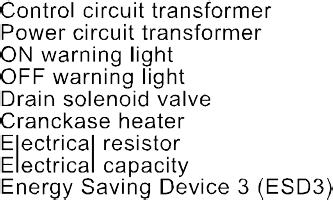
2 1. Important safety notes - Please read Transportation Positioning Installation Before operating Maintenance by an engineer Maintenance by the user Introduction Operation Technical specifications Diagrams General Arrangements Main Settings Drawings Components location Troubleshooting Warranty... 63
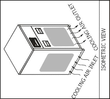
3 A) When operating the air dryer the operator must apply safe working methods and observe all local safety instructions and relevant regulations. B) Prior to installation, the dryer and the compressed air system are to be depressurized and disconnected from the electrical main supply. C) The user is responsible for safe operating conditions. Parts and accessories must be replaced if inspection shows that safe operation cannot be assured. D) Installation, operation, maintenance and repair are only to be authorized, trained and skilled engineers. E) The minimum and maximum values stated must be observed, as well as all of the safety precautions described in this manual. F) If any statement in this manual does not comply with the local legislation, the strongest standard is to be applied Transportation A) Use care and caution when transporting the dryer. Avoid dropping and other physical abuse. B) A forklift can be used to transport the dryers provided the forks are long enough to support its full width or length and caution is used throughout the move Positioning A) The dryer must be installed horizontally. A minimum of 20 clearance around the dryer is necessary to allow a good ventilation and easy access for servicing. B) The ambient temperature in the room should not exceed 122 F and should not be below 39 F, taking the heat radiated by the dryer into account. C) (40 watt for each liter/sec under ISO 7183-A condition or 18 watts for each SCFM under ISO 7183-B condition) Installation A) In addition to the general mechanical construction procedures and local regulations, the following instructions need to be emphasized: 1) Only authorized, trained and skilled engineers should install the compressed air dryer. 2) Safety devices, protecting covers or insulation in the dryers never to be dismantled or modified. Each pressure vessel or accessory installed outside the dryer with air above atmospheric pressure must be fitted with the required pressure relief safety valves Before Operating A) Review all safety precautions. B) The piping must have the correct diameter and be adapted to the operating pressure (see technical specification). C) Never operate the dryer at pressure above the maximum specified on the dryer label (check the technical specs too) Maintenance by an Engineer A) Maintenance and repairs should only be performed when the air dryer is shut down and depressurized and when the main power switch is turned off. B) Use only the appropriate tools for maintenance and repair. C) Before dismantling a part under pressure, disconnect the pressure sources and depressurize the system. D) Proceed carefully during maintenance and repair. Prevent dirt from entering by covering parts and orifices with a clean cloth, paper or tape. A receiver should never be welded or modified in any way. E) Never leave tools, loose parts or cleaning rags in or on the air dryer. F) Before returning the dryer into service, check the setting of the control and safety devices as well as the pressure and the temperature of the compressed air circuit Maintenance by the user A) Keep the dryer clean. B) Regularly check the correct operation of the condensate drain trap. C) Every six months, check and clean the drain strainer by undoing the access screw and rinsing the filter with tap water to remove the trapped dirt from the inside. 1
 Check the trouble-shooting list in case of maintenance troubles. G) Check operating pressures, temperatures and time settings after maintenance.")
 Manufacturer: B) Purpose of this dryer 1) This refrigerated compressed air dryer has been designed to remove water vapor from industrial compressed air.")
4 D) For air cooled dryers, clean the air condenser as soon as it s dirty or clogged. E) For optional water-cooled condensers, use only clean water and install a water filter if needed. Use water counter flow to clean condenser if need. F) Check the trouble-shooting list in case of maintenance troubles. G) Check operating pressures, temperatures and time settings after maintenance. If operating and safety devices function properly, the air dryer may be used. A) Manufacturer: B) Purpose of this dryer 1) This refrigerated compressed air dryer has been designed to remove water vapor from industrial compressed air. 2) This dryer has been designed for indoor operation. 3) The minimum and maximum values stated must be observed, as well as the safety precautions described in this manual. C) Dryer label The following label is affixed on the cabinet of the refrigerant compressed air dryer. D) Working details 1) Refrigerant circuit: The refrigerant circuit can be divided in 3 parts: a) Low pressure section with an evaporator (heat exchanger) b) High-pressure section including: Condenser, liquid receiver, (if installed) and the filter dryer. c) Control circuit including: Compressor, Expansion valve, by-pass valve (if installed), Fan pressure switch (if installed) 2) For water - cooled dryers: a) Water valve b) Safety high pressure switch (if installed) 3) The Refrigerant circuit operates as follows: a) The compressor compresses gaseous refrigerant to a high temperature. b) The hot refrigerant condenses in the condenser. Being liquefied it is stored in the liquid receiver (if installed). c) The liquid is taken out the storage vessel and injected in the evaporator (heat exchanger) by an expansion valve. This expansion valve is protected by a filter, which removes particles and humidity that could be in the circuit. d) The injected liquid fills in the refrigerant section of the air / refrigerant heat exchanger and evaporates by taking out the calories from the compressed air. The gaseous refrigerant is sucked in the compressor and the cycle carries on. e) In order to keep the evaporation pressure steady, and thus the refrigerant temperature in the heat exchanger, a by-pass valve is injecting hot gaseous refrigerant in the circuit. On certain dryers, an automatic expansion valve regulates this. 4) Compressed air circuit a) The saturated hot compressed air flows into the Economiser where it is pre-cooled by the out flowing dry chilled air. In the cold zone of the air refrigerant section it continues to cool 2
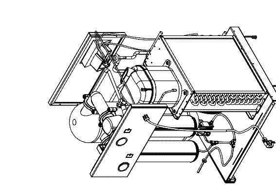
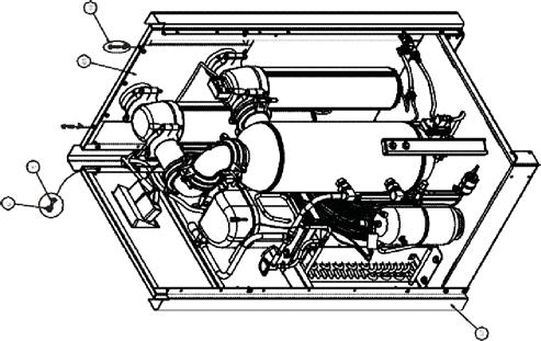
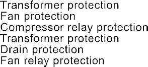
5 down to dew point and enters the separator where condensates are collected. The outgoing chilled air is then warmed up in the economizer by the hot incoming air. b) The condensates are collected after centrifugal separation and drained out through the automatic trap. c) As long as the compressed air temperature does not drop below dew point, there will be no condensation in the air circuit. 5) Refrigerant compressor Being of the hermetic type, it requires no servicing. 6) Condenser a) Th e air condensers are equipped with a helecoidal at the condenser refrigerant level. On certain type of dryers, a water-cooled condenser can be fitted. b) In this case, a water valve being driven by the refrigerant circuit is taking care of its regulation. 7) Refrigerant circuit protection a) Klixon: The single phase compressors are equipped with a klixon which is a thermal sensitive switch controlling the temperature of the compressor and possible over intensity. In case of malfunction, the klixon trips but switches on again automatically as soon as the compressor has cooled down. b) High Pressure Security Switch: Refrigerant line is considered as a pressure vessel. That is why it is protected against bursts by the help of manually reset switch. It is set to psi for dryers working with R134a c) Filter dryer: A refrigerant circuit is a closed circuit and total water removal in the refrigerant circuit is paramount in order to obtain a correct functioning. d) To avoid problems, the refrigerant circuit must be vacuumed before loading the refrigerant. It is equipped with a filter dryer, which also traps any solid particles, which may have migrated into the circuit during assembly. e) Water-cooled dryers have a safety high-pressure switch. In case of cooling water failure, the safety switch stops the dryer. When the safety switch has tripped out, it has to be manually resettled before switching on the dryer. 8) Refrigerant circuit controls a) Liquid refrigerant injection: The liquid refrigerant is into the evaporator by a control valve. This valve is a thermostatic or pressostatic one maintaining a constant overheats of the refrigerant in the evaporator(s). b) Constant evaporating pressure: In the dryers equipped with a by-pass valve, the evaporating pressure is kept constant by a controlled injection of hot gas from the high-pressure side into the low-pressure section of the circuit. 9) Condensate drain - trap assembly Dismantling the drain is easy because it can be isolated from the air circuit under pressure with a ball valve. The drain has to be depressurized before being dismantled. 10) Heat Exchanger Modular design a) The dryers are equipped with a compact Mono Bloc Heat Exchanger module. This assembly has been specially designed to dry compressed air and is made of: 1) An Economiser which pre-cools the entering hot air with the out flowing cold air. 2) An air/refrigerant exchanger cooling down the compressed air. 3) A centrifugal separator concentrating all condensates and requiring no maintenance. 11) Accessories a) Dew point indicator: Located on the control panel, it displays the value of the pressure dew point. b) Temperature switch: Located inside the dryer, this temperature switch is adjustable from 32 F up to 95 F c) Energy Saving Device: (ESD) This device helps dryer save energy when there is not any compressed air flow in the dryer. (Please see the models have standart and optional in next page) d) Filter change alarm on the front panel 3
 Dewpoint indicator (Standard) 2) Filter change Alarm** 5 3) Start / Stop Button 1) Dewpoint indicator (Standard) 2) Start Light 3) N/A 4) Filter change Alarm** 5) Main")
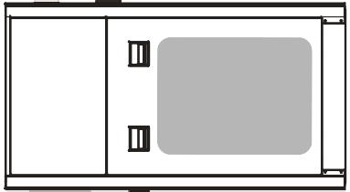
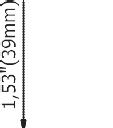
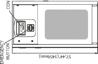
6 3.1. Operation A) Control panels: The control panel of the dryer includes the following elements: Monophase PDRCF PDRCF Dew point indicator Monophase DN120-US - DN130-US Dew point indicator ) Dewpoint indicator (Standard) 2) Filter change Alarm** 5 3) Start / Stop Button 1) Dewpoint indicator (Standard) 2) Start Light 3) N/A 4) Filter change Alarm** 5) Main Switch Triphase ESD3 PDRCF PDRCF ) ESD3 (Standard) 5) EMERGENCY STOP ** IMPORTANT NOTE: The Dryer has two Compressed Air Filter inside. It is better to change filter element for the best efficiency when the alarm light is active. It is recommended to keep replacement filter elements in your stock in order to replace them when needed. ATTENTION : DN-US range dryers have low pressure drop according its competitors. Do not use DN-US range dryers together with other dryers which have higher pressure drop without getting the confirmation from our technical team. 4
7 3.2. During Operation Regularly check the digital temperature controller ESD3 or dew point indicator on dryer. B) Start up and shut-down Warning: Avoid leaving the dryer off when compressed air is still flowing through it. C) Starting for the first time or after a long stop 1) Set the rotary switch to I This preheats the dryer and turns the drain system on. It is recommended to leave the dryer power on permanently so the crankcase heater runs continuously. 2) IMPORTANT NOTE! After a long stop of the dryer it is MANDATORY to allow a preheating period of minimum 4 hours before starting again, to avoid any compressed air flow during preheating. 3) Follow the daily starting and shut down procedure. D) Daily starting and shut-down 1) Push on the green button to start the dryer. 2) The start light will indicate that the dryer is running. 3) To stop the dryer, first stop the airflow (either shut-down the air compressor or close the inlet/outlet or by-pass valve) When the air flow is stopped set the rotary switch on 0 Set it again on I in order to keep the preheating on. 4) IMPORTANT NOTE! Avoid leaving the dryer stopped when compressed air is still flowing through it. 5) To switch the already preheated dryer on again, simply push the green start button. E) Digital Temperature Control technical features (ESD3) ESD3: PLC clear text multilingual indication of alarms, maintenance and running hours + Energy Saving Device automatic switching OFF at no load and ON when warm compressed air is entering. (Please see the ESD3 manual which is given with Dryer) 5
8
9 Total Electric Power Max Work pressure (bars) Max Ambient Temperatu Model Capacity (CFM) Connection Size Voltage Refrigerant Type Pressure Drop Max inlet Temp. PDRCF /2" R134a < PDRCF /4" R134a < PDRCF /2" R134a < PDRCF /2" R134a < PDRCF " R134a < PDRCF " R134a < PDRCF " R134a < PDRCF " R134a < PDRCF " R134a < PDRCF " R134a < PDRCF " 460 R134a < PDRCF " 460 R134a < For All Models Maximum Pressure Maximum Ambient Temperature Minimum Ambient Temperature Maximum Inlet Temperature 232 PSI 122 F 40F 140 F 7
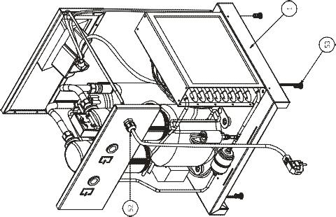
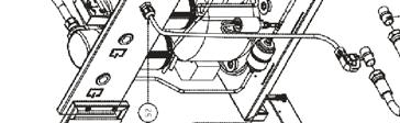
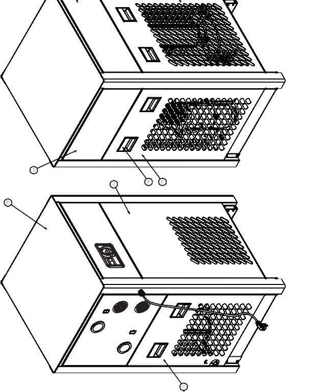
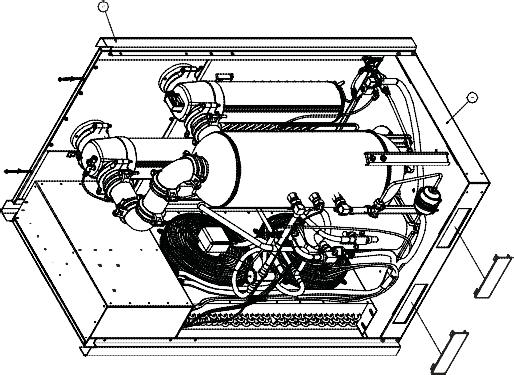
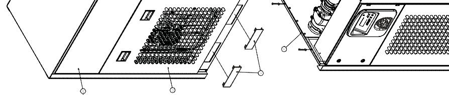
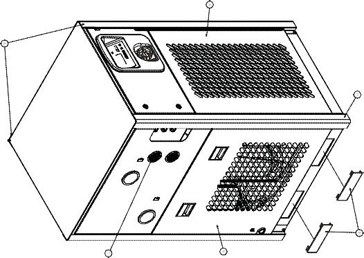
10 EDRCF EDRCFR IMPORTANT NOTICE: 5: Only From Dryer PDRCF to PDRCF : Only from Dryer PDRCF to PDRCF M 8

11 9

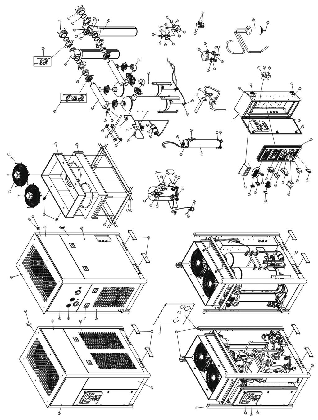
12 Electrical Circuit 10
13 12 Electrical Circuit

14 Electrical Circuit 15
15 Electrical Power Circuit 16
16
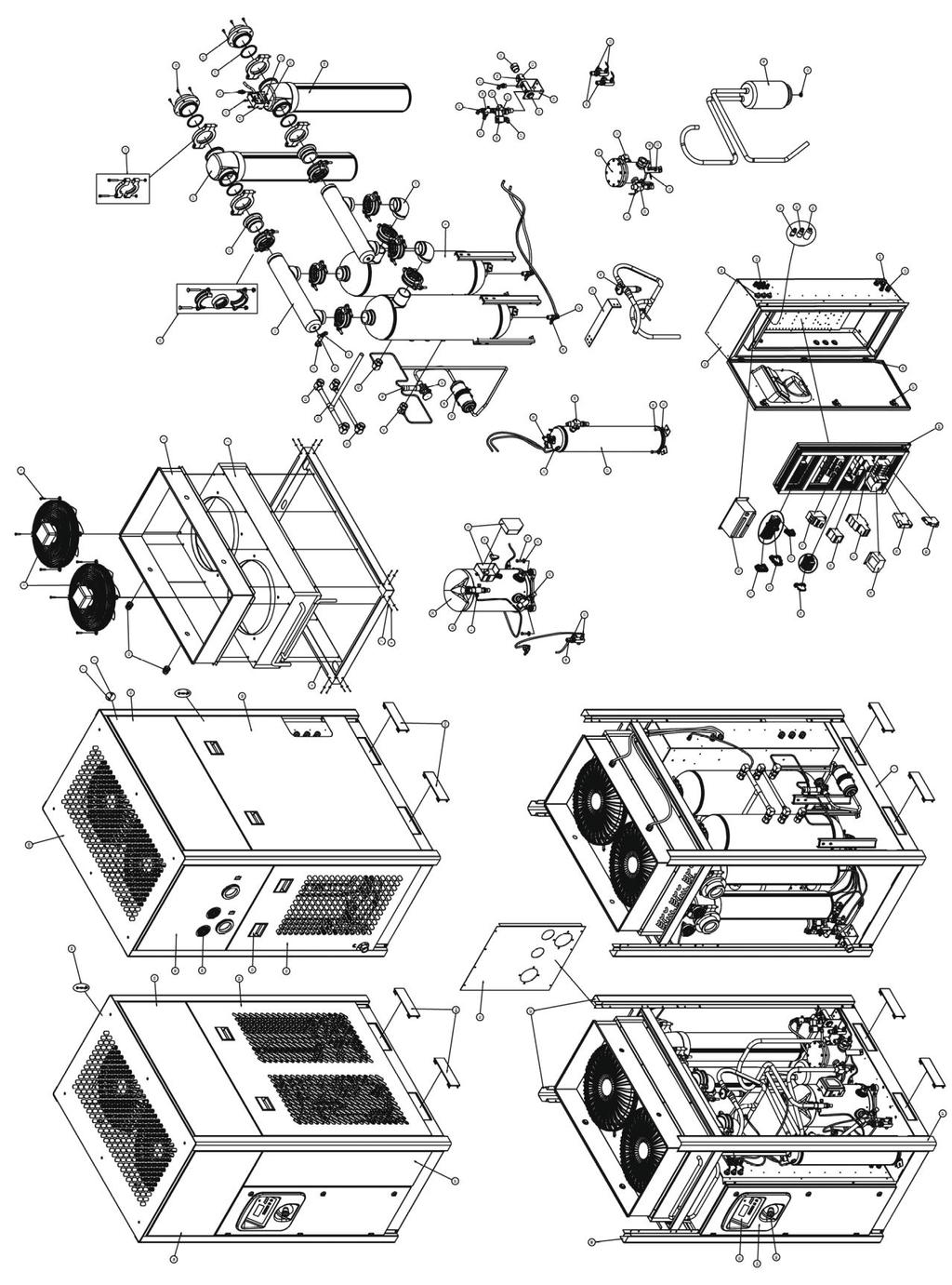
17 Model 1 * GKO50X + 1 * GKO50Y MKO50 KIT * GKO50X + 1 * GKO50Y MKO50 KIT * GKO50X + 1 * GKO50Y MKO50 KIT * GKO150X + 1 * GKO150Y MKO150 KIT * GKO150X + 1 * GKO150Y MKO150 KIT * GKO150X + 1 * GKO150Y MKO150 KIT * GKO500X + 1 * GKO500Y MKO500 KIT * GKO500X + 1 * GKO500Y MKO500 KIT * GKO500X + 1 * GKO500Y MKO500 KIT * GKO851X + 1 * GKO851Y MKO851 KIT * GKO1210X + 1 * GKO1210Y MKO1210 KIT * GKO1210X + 1 * GKO1210Y MKO1210 KIT * GKO1210X + 1 * GKO1210Y MKO1210 KIT * GKO1820X + 1 * GKO1820Y MKO1820 KIT * GKO1820X + 1 * GKO1820Y MKO1820 KIT * GKO2700X + 1 * GKO2700Y MKO2700 KIT * GKO2700X + 1 * GKO2700Y MKO2700 KIT Superheat of thermostatic expansion valve 41 O F - 50 O F Evaporating pressure 29.7 psi Fan pressure switch psi Security (*) high pressure switch psi (*) Available up to Dryair DN40-US and above (**) Available up to Dryair DN140-US and above (***) 1 min. - 5 sec. (up to DN100-US and above) 5 min. - 4 sec. (up to DN90-US and above) (****) Available up to Dryair DN140-US and above Security (**) low pressure switch 23.2 psi Drain timer (***) 1 min sec. 5 min sec. Low pres. High Temp. switch (****) 113 O F Water flow valve (if water condenser) psi 18
18 19
19 20
20 21
21 22
22 23
23 24
24 25
25 26
26 27
27 28
28 29
29 30
30 31
31 32
32 60
33 Dryer is switched on, indicator light is lit but the refrigerant compressor does not turn on. The connection has inverted phases Refrigeration unit is not functioning Invert two phases Check refrigeration compressor 3-phase dryers are equipped with a phase controller to avoid the fans from turning in the opposite direction. Several factors can cause compressor failure. A qualified refrigeration technician needs to check all the electrical and refrigerant circuit and controls. The refrigerant high pressure protection has tripped The refrigerant safety high pressure switch has tripped. The dryer is protected against excessively high refrigerant pressure. If the condenser efficiency has reduced, the switch will trip. Manually reset the switch. In case of water cooled condensers, check the water control valve Excessive ambient temperature Be sure that dryer is working in temperatures lower than the design conditions. Designed conditions and correction factors are described in this manual. A high ambient temperature may cause the refrigerant system to operate at higher than normal pressures. Results will be higher than normal evaporator temperature. lmportant: adequate air circulation around the dryer, and proper ventilation in the equipment room should guarantee a low enough ambient temperature. Dryer is switched on, but the refrigerant compressor does not turn on. Excessive temperature on crankcase of compressor. Excessive compressed air inlet temperature. Allow time to compressor to cool down. Reason may be a possible incorrect adjustment of hot gas bypass valve or shortage of refrigerant Be sure that dryer is working in temperatures lower than design conditions. Compressor is protected against overly high temperatures of the crankcase by a thermal switch. The dryer is designed for working in calculated conditions (see description in this manual). If conditions are exceeded, the dryer will be overflowed, dew point will go up and protecting devices can switch off. Clogged condenser fins or clogged water condenser. Possible high crankcase temperature Possible loss of phase Possible low voltage causing overload trip Possible failed compressor Clear fins or water condenser of all obstructions. The clogged fins in the condenser will restrict the air passage and reduce the refrigeration capacity, causing high temperature in the evaporator. Same will occur if water condenser is clogged with mud or dirt. Air condenser and water condenser should be periodically checked and cleaned. Protect water circuit by an adapted filter. Too much compressed air flow. Check actual flow through the dryer. This dryer is designed for a maximum air flow at design conditions. If too much air is pumped into the dryer, water removal capacity may not be sufficient, resulting in liquid carryover down stream. Check the rated output the air compressor. Faulty electrical wiring Inspect the circuit The compressor-on light should be wired into the refrigerant compressor circuit. See wiring diagrams in this manual. One electrical protection has tripped. Reset the protection or replace the blown fuse. The dryer is protected against high amp draw by fuse and/or overload relay that can trip in case of need. Reset or replace fuse once, but do not persist if it trips again, request assistance from a qualified refrigeration contractor. Dryer is switched on but fan is not running. Fan has to run if refrigerant high pressure reaches upper set point. Check that compressed air flows through the dryer. Check that fan blades are free to move. Check the fan pressure switch. Fan operates automatically to keep refrigerant pressure below the maximum value. The fan can stop if pressure is under the recommended setting. When compressor starts, it vibrates a lot and makes mechanical noise. Compressor is slugging liquid refrigerant at start up. Be sure the pre-heating period of at least 2 hours is respected Refrigerant may move between receivers when refrigerant compressor is stopped and not heated, especially if stopped for a long time. This migration may cause liquid shock (slugging) in valves specially on large dryers containing more refrigerant 61
34 Water in system High pressure drop The unit will not run or cycles off and on. Compressed Air Inlet and outlet connections are reversed. Drain system is clogged or inoperative. Check inlet and outlet connections. Restore a free flow of water condensate. Check water evacuation. This dryer is designed for air flow in one direction only. Inlet and outlet directions are identified on the dryer. Drain system is timed solenoid valve, pneumatically assisted which has to be adjusted in accordance with values listed in this manual. The Solenoid valve includes a strainer that has to be periodically checked and cleaned. Membranes of pneumatically assisted drain have to be checked or replaced every 6 months. Bypass system is open Check the valves Important: Bypass piping should be installed around the dryer so the dryer can be isolated for service without shutting down the air supply. During dryer operation, valves must be set so all air goes into the system. Check tightness of the bypass system. Free moisture remains in pipe lines. Blow out the system Before the dryer is first started all free moisture should be blown out of the system. Excessive air flow Excessive free moisture Excessive compressed air inlet temperature. Check actual flow through the dryer. Check the separator and drain system and compressor after cooler ahead of the dryer. Be sure that dryer is working lower than design conditions This dryer is designed for a maximum air flow. If too much air is pumped into the dryer, water removal capacity may not be sufficient, resultingin liquid Carry over downstream. Check the rated flow of the air compressor. In some system there may be an accumulation of free moisture in the line ahead of the dryer. If this moisture is pumped into the dryer intermittently, the water removal capacity may not be sufficient. A water separator should be installed in the line before the dryer. The dryer is designed to work for calculated design conditions. Should the conditions be exceeded, the dryer will be overflowed, dew point will go up and protecting devices can switch off. Clogged condenser fins Clear fins of all obstructions The clogged fins in the condenser will restrict air passage and reduce refrigerant capacity causing water downstream. Fins should be periodically checked and cleaned. Shortage of refrigerant Refrigeration system is not functioning Excessive pressure dew point Excessive compressed air flow or too law air inlet pressure. Freeze up Clogged heat exchanger Line disconnect switch is open. Fuse or breaker is open Faulty refrigerant compressor or controls. Excessive compressed air inlet temperature. Fix the leak and add a charge of refrigerant. Check to be certain refrigerant compressor is running Readjust refrigerant evaporating pressure Check actual pressure and flow through the dryer. Check that compressor room ambient, Fan switch could have failed in closed position keeping fan on. Clean heat exchanger with areverse air flow. Close the start or disconnect switch. Replace fuse or reset breaker. Determine the cause and make correction Design conditions and correction factors are described in this manual. Be sure that dryer is working in ambient temperatures below design conditions. Loss of refrigerant will cause improper functioning. A qualified, refrigeration specialist should perform the necessary repairs, or factory should be contacted if the unit is in warranty. To check if the compressor is running, check compressor-on light. lt is possible for the fan to be operating but not the compressor. Compressor not running can be caused by several taeters. A qualified refrigeration technician should check all refrigerant and electrical controls The refrigerant pressure adjustment should be done by a qualified refrigeration engineer. This is a very sensitiye device and incorrect settings may create other failures. This dryer is designed for a maximum air flow. If too much air is pumped into the dryer, water removal capacity may not be sufficient, resulting in l iquid carry-over downstream. Check the rated flow of the air compressor. Frosting of the Iines is an indication that controls are set too low. The following should be done by an experienced ref rigeration technician. Controls may be adjusted in the fields by means of the hot gas bypass valve. This is to be done by a qualified refrigerant technician. Dryer are supposed to be used with compressed air free of any aggressive contaminants. Some contamination may require extra maintenance of the heat exchanger. If the dryer is not operating, check the disconnect switch or circuit breaker to be certain it is on. The fuse to the power line should be checked and replaced if needed. Never replace a burnt fuse with an oversized fuse. Failure of compressor to run may be caused by several factors. A qualified refrigeration specialist should check all electrical and refrigeration controls, or factory should be contacted if unit is in warranty. The dryer is designed for working into calculated design conditions. Should the conditions be exceeded, the dryer will be overflowed, dew point will go up and protecting devices may trip. 62
35 The unit will not run or cycles off and on. Excessive ambient temperature Designed conditions and correction factors are described in dryer. Be sure that dryer is working lower than design conditions. A high ambient temperature may cause the refrigerant system to operate at higher than normal pressures. Results will be a higher than normal evaporator temperature. Important: there should be adequate air circulation around the dryer, and proper ventilation in the equipment room should guarantee a low enough ambient temperature. Clogged condenser fins Clear fins of all obstructions. The clogged fins in the condenser will restrict the air passage and reduce the refrigeration capacity, causing high temperature in the evaporator. Fins should be periodically checked and cleaned. Shortage of refrigerant Fix the leak and add a charge of refrigerant. Loss of refrigerant will cause improper functioning. Dryers are equipped with a temperature switch which maintains the amount of refrigerant to maintain proper cooling of the compressor. A shortage of refrigerant may cause suction line to become very hot, causing the temperature switch to trip. A qualified refrigeration specialist should perform the necessary repairs. Error sign occurs on digital temperature control device The dew point is too low or too high. Check refrigerant gas and make sure that the working conditions are within the correct range. If there is not enough refrigerant gas or if the working temperature and inlet temperatures are very high, the dew point will increase. When used under the conditions recommended the heat exchanger will be warranted for five (5) years. This warranty is limited to the replacement of the heat exchangers, Some restrictions as outlined below concerning misuse, abuse or accident. The standard equipment external float drain and automatic drain carry a 90-day warranty. This warranty will apply to equipment installed, operated and maintained in accordance with the procedures and recommendations as outlined in the owner s manual published by Emax During the life of this warranty, Emax will repair or replace (at Polar airs option) any defective part or assembly free of charge if such defect occurred in normal service and was not due to apparent misuse, abuse or accident.. Customer is responsible for shipping charges. This Warranty is not transferable. Any warranty service performed in the field must be authorized by EMAX air Unauthorized service voids the warranty and any resulting charges will not be paid by Emax Polar air makes no other warranties or guarantees, expressed or implied. Polar air assumes no liability for indirect or consequential damages. 63
Polar Air Dryer. Instructions Manual PDRCF PDRCF R E F R I G E R A T E D T Y P E C O M P R E S S E D A I R D R Y E R S
 Polar Air Dryer R E F R I G E R A T E D T Y P E C O M P R E S S E D A I R D R Y E R S PDRCF1150029 PDRCF4602000 Instructions Manual TABLE OF CONTENTS 1. Important safety notes - Please read... 1 1.1. Transportation...
Owner s Manual Refrigerated Compressed Air Dryers Models F-3528, F-3529, F-3530, F-3531 & F-3532
 Owner s Manual Refrigerated Compressed Air Dryers Models F-3528, F-3529, F-3530, F-3531 & F-3532 Read carefully before attempting to assemble, install, operate or maintain the product described. Protect
Owner s Manual Refrigerated Compressed Air Dryers Models F-200, 250, 300 & F350
 Owner s Manual Refrigerated Compressed Air Dryers Models F-200, 250, 300 & F350 Read carefully before attempting to assemble, install, operate or maintain the product described. Protect yourself and others
Owners Manual Refrigerated Air Dryer MHT SERIES
 Owners Manual Refrigerated Air Dryer MHT SERIES IMPORTANT: READ THIS MANUAL CAREFULLY. IT CONTAINS IN- FORMATION ABOUT SAFETY AND THE SAFETY OF OTHERS. ALSO BECOME FAMILAR WITH THE PROPER INSTALLATION
NEWGATE TECHNOLOGIES, INC.
 www W.newgatetechnologies.com NEWGATE TECHNOLOGIES, INC. Installation & Operations Manual SYNERGY Series High Inlet Temperature Refrigerated Air Dryers Models SYNERGY 025 ~ SYNERGY 125 Includes Safety
Owner s Manual Refrigerated Compressed Air Dryers Model F-100
 Owner s Manual Refrigerated Compressed Air Dryers Model F-100 Read carefully before attempting to assemble, install, operate or maintain the product described. Protect yourself and others by observing
Owners Manual UA75 TO UA1200 SERIES Refrigerated Air Dryer
 1 Owners Manual UA75 TO UA1200 SERIES Refrigerated Air Dryer DESCRIPTION PAGE INTRODUCTION 2 INSTALLATION 3 INSTALLATION GUIDE 4 DRYER CONTROLS 5 DRYER CONTROLS AND SAFTEY SHUTDOWNS 6 START UP 6 INITIAL
Owner s Manual Refrigerated Compressed Air Dryer Model F-50
 Owner s Manual Refrigerated Compressed Air Dryer Model F-50 Read carefully before attempting to assemble, install, operate or maintain the product described. Protect yourself and others by observing all
EBAC MODEL CD30 INDUSTRIAL DEHUMIDIFIER OWNER S MANUAL
 EBAC MODEL CD30 INDUSTRIAL DEHUMIDIFIER OWNER S MANUAL Ebac Industrial Products 704 Middle Ground Boulevard Newport News, VA 23606 Tel: 757 873 6800 Fax: 757 873 3632 Website: www.ebacusa.com UNPACKING
DRYMAX DRYMAX DRYMAX DRYMAX
 DRYMAX DRYMAX 897-8485 DRYMAX DRYMAX 905 RECEIVING AND INSPECTION 1. The dryer cannot be tilted on its side or upside down during shipping. 2. Use forklift from the bottom of the dryer when installing
Trouble Shooting Guide PWA, 3-phase (D10571)
") Trouble Shooting Guide PWA, 3-phase (D10571) Trouble Shooting Guide Problem Possible Cause Possible Remedy Unit does not start Unit does not cool No power to unit, breaker tripped Low voltage Loose wire
Trouble Shooting Guide PWA, 3-phase (D10571) Trouble Shooting Guide Problem Possible Cause Possible Remedy Unit does not start Unit does not cool No power to unit, breaker tripped Low voltage Loose wire
Trouble Shooting Guide FAA, 3-phase (D3631)
") Trouble Shooting Guide FAA, 3-phase (D3631) Trouble Shooting Guide Problem Possible Cause Possible Remedy Unit does not start Unit does not cool No power to unit, breaker tripped Low voltage tripped Loose
Trouble Shooting Guide FAA, 3-phase (D3631) Trouble Shooting Guide Problem Possible Cause Possible Remedy Unit does not start Unit does not cool No power to unit, breaker tripped Low voltage tripped Loose
EBAC MODEL CD30 INDUSTRIAL DEHUMIDIFIER OWNER S MANUAL
 EBAC MODEL CD30 INDUSTRIAL DEHUMIDIFIER OWNER S MANUAL Ebac Industrial Products, Inc. 700 Thimble Shoals Blvd, Suite 109 Newport News, VA. 23606-2575 Tel: (757) 873 6800 Fax: (757) 873 3632 Website www.ebacusa.com
EBAC MODEL AD850 INDUSTRIAL DEHUMIDIFIER OWNER S MANUAL
 EBAC MODEL AD850 INDUSTRIAL DEHUMIDIFIER OWNER S MANUAL Ebac Industrial Products 704 Middle Ground Boulevard Newport News VA 23606 Telephone (757) 873-6800 FAX (757) 873-3632 Website: www.ebacusa.com INTRODUCTION
EBAC MODEL CD60 INDUSTRIAL DEHUMIDIFIER OWNER S MANUAL
 EBAC MODEL CD60 INDUSTRIAL DEHUMIDIFIER OWNER S MANUAL CD60 OWNERS MANUAL Page 1 of 9 INTRODUCTION Designed for a wide range of applications, the CD60 dehumidifier is a rugged, industrial unit which utilizes
Trouble Shooting Guide RAA, 1-phase (D3627)
") Trouble Shooting Guide RAA, 1-phase (D3627) Trouble Shooting Guide Problem Possible Cause Possible Remedy Unit does not start Unit does not cool No power to unit, breaker tripped Low voltage tripped Loose
Trouble Shooting Guide RAA, 1-phase (D3627) Trouble Shooting Guide Problem Possible Cause Possible Remedy Unit does not start Unit does not cool No power to unit, breaker tripped Low voltage tripped Loose
NON-CYCLING REFRIGERATED AIR/GAS DRYERS QPNC 75 to QPNC 250 OPERATOR S MANUAL
 NON-CYCLING REFRIGERATED AIR/GAS DRYERS QPNC 75 to QPNC 250 OPERATOR S MANUAL DATE OF PURCHASE: MODEL: SERIAL NO.: Record above information from nameplate. Retain this information for future reference.
Trouble Shooting Guide PAA, 1-phase (D3731)
") Trouble Shooting Guide PAA, 1-phase (D3731) Trouble Shooting Guide Problem Possible Cause Possible Remedy Unit does not start Unit does not cool No power to unit, breaker tripped Low voltage tripped Loose
Trouble Shooting Guide PAA, 1-phase (D3731) Trouble Shooting Guide Problem Possible Cause Possible Remedy Unit does not start Unit does not cool No power to unit, breaker tripped Low voltage tripped Loose
EBAC MODEL KOMPACT INDUSTRIAL DEHUMIDIFIER OWNER S MANUAL
 EBAC MODEL KOMPACT INDUSTRIAL DEHUMIDIFIER OWNER S MANUAL KOMPACT OWNERS MANUAL Page 1 of 9 INTRODUCTION Designed for a wide range of applications, the Kompact is a rugged, industrial unit, which utilizes
GRF-SERIES REFRIGERATION TYPE NON CYCLING STANDARD
 Great Lakes Air Products 1515 S. Newburgh Road Westland, MI 48186 PH: 734-326-7080 www.glair.com COMPRESSED AIR DRYER INSTRUCTION MANUAL GRF-SERIES REFRIGERATION TYPE NON CYCLING STANDARD Contents Introduction
PROdry. High Inlet. Temperature. refrigerated. compressed air. dryers. Contents. For Sales & Service please contact:
 7610.724.11B 10/01 INSTRUCTION MANUAL Contents 1.0 INSTALLATION... 2 2.0 OPERATION... 3 3.0 MAINTENANCE... 4 TROUBLESHOOTING GUIDE... 6 SPECIFICATIONS... 7-8 ELECTRICAL SCHEMATICS... 9 DIMENSIONS AND WEIGHTS...
EBAC MODEL NEPTUNE INDUSTRIAL DEHUMIDIFIER OWNER S MANUAL
 EBAC MODEL NEPTUNE INDUSTRIAL DEHUMIDIFIER OWNER S MANUAL NEPTUNE OWNERS MANUAL Page 1 of 9 INTRODUCTION Designed for a wide range of applications, the Neptune dehumidifier is a super high capacity industrial
GTX Series Thermal Xchange Cycling Refrigeration Dryers GREAT LAKES AIR ANDARD ELECTRONIC DRAIN 5 -YEAR WARRANTY F PRESSURE DEWPOINT
 GREAT LAKES AIR ANDARD ELECTRONIC DRAIN STANDARD ELECTRONIC 5 -YEAR WARRANTY 35-39 F PRESSURE DEWPOIN SS EXPANSION VALVE STANDARD ELECTRONIC DRAIN 35-39 F PRESSURE DEWPOINT GTX Series Thermal Xchange Cycling
EBAC MODEL BD-150 ( ) INDUSTRIAL DEHUMIDIFIER OWNER S MANUAL
 INDUSTRIAL DEHUMIDIFIER OWNER S MANUAL") EBAC MODEL BD-150 (1025000) INDUSTRIAL DEHUMIDIFIER OWNER S MANUAL BD-150 OWNERS MANUAL Page 1 of 12 INTRODUCTION Designed for a wide range of applications, the BD-150 dehumidifier is a super high capacity
EBAC MODEL BD-150 (1025000) INDUSTRIAL DEHUMIDIFIER OWNER S MANUAL BD-150 OWNERS MANUAL Page 1 of 12 INTRODUCTION Designed for a wide range of applications, the BD-150 dehumidifier is a super high capacity
OWNER/OPERATOR MANUAL COMPONENTS, INSTALLATION, OPERATION AND SERVICE INSTRUCTIONS
 OWNER/OPERATOR MANUAL COMPONENTS, INSTALLATION, OPERATION AND SERVICE INSTRUCTIONS REFRIGERATED COMPRESSED AIR DRYER WRA-0050 WRA-0200 WARNING READ ALL INFORMATION IN THIS MANUAL BEFORE BEGINNING INSTALLATION
RPI Industries, Inc.
 RPI Industries, Inc. AIR SCREEN and SELF-SERVE OPERATION AND SERVICE MANUAL WARRANTY INFORMATION For Models Stratus SCRFC48R-SSI SCRFC60R-SSI SCRFC72R-SSI SCRFC48R-SSII SCRFC72R-SSII SCRFC48R-SSIII SCRFC72R-SSIII
Standard and CELDEK Evaporative Cooler Modules Installation, Operation, and Maintenance Manual
 Standard and CELDEK Evaporative Cooler Modules Installation, Operation, and Maintenance Manual Standard Evaporative Cooler CELDEK Evaporative Cooler RECEIVING AND INSPECTION Upon receiving unit, check
CELDEK Evaporative Cooler Module Installation, Operation, and Maintenance Manual. CELDEK Evaporative Cooler
 CELDEK Evaporative Cooler Module Installation, Operation, and Maintenance Manual CELDEK Evaporative Cooler RECEIVING AND INSPECTION Upon receiving unit, check for any interior and exterior damage, and
EBAC MODEL WM150 INDUSTRIAL DEHUMIDIFIER OWNER S MANUAL
 EBAC MODEL WM150 INDUSTRIAL DEHUMIDIFIER OWNER S MANUAL WM150 OWNERS MANUAL Page 1 of 9 INTRODUCTION Designed for a wide range of applications, the WM150 is a rugged, industrial unit, which utilizes an
ORTEC HIGH CAPACITY REFRIGERATED AIR/GAS DRYERS
 ORTEC Compressed Air, Gas & Fluid Technologies HIGH CAPACITY REFRIGERATED AIR/GAS DRYERS Energy Lean Planet Green Cycling and Non-Cycling Design Energy Efficient s Fluctuating and Intermittent Loads Capacity,0
Standard and CELDEK Evaporative Cooler Modules Installation, Operation, and Maintenance Manual
 Standard and CELDEK Evaporative Cooler Modules Installation, Operation, and Maintenance Manual Standard Evaporative Cooler CELDEK Evaporative Cooler RECEIVING AND INSPECTION Upon receiving unit, check
CHEST FREEZER INSTRUCTION MANUAL. Model No.: EWCF5WBX EWCF7WBX
 CHEST FREEZER INSTRUCTION MANUAL Model No.: EWCF5WBX EWCF7WBX To ensure proper use of this appliance and your safety, please read the following instructions completely before operating this appliance.
4.5 CU.FT. REFRIGERATOR INSTRUCTION MANUAL
 4.5 CU.FT. REFRIGERATOR INSTRUCTION MANUAL Model No.: MCBR465S To ensure proper use of this appliance and your safety, please read the following instructions completely before operating this appliance.
Rev. None AUGUST 2012 MDM SERIES MODULAR MEMBRANE AIR DRYERS OPERATOR MANUAL MDM1 MDM4 MDM9 MDM13 MDM24 MDM49 MDM66 MDM106 MDM138
 7428146 Rev. None AUGUST 2012 MDM SERIES MODULAR MEMBRANE AIR DRYERS OPERATOR MANUAL MDM1 MDM4 MDM9 MDM13 MDM24 MDM49 MDM66 MDM106 MDM138 1.0 SAFETY All compressed gases, including air, can be dangerous.
Condensing Unit Installation and Operating Instructions
 Bulletin WCU_O&I 01 June 2003 Condensing Unit Installation and Operating Instructions WCU Air Cooled Condensing Unit Table of Contents Section 1. Section 2. Section 3. Section 4. Section 5. Section 6.
CD30 / CD30E INDUSTRIAL DEHUMIDIFIER OWNER S MANUAL
 CD30 / CD30E INDUSTRIAL DEHUMIDIFIER OWNER S MANUAL www.eipl.co.uk Page 1 of 8 Product Support Questions: Contact Ebac USA at (757) 873 6800 Sales Inquiries: Contact Sylvane at (800) 934-9194 or visit
HTD. High Temperature Non-Cycling Refrigerated Compressed Air Dryers. Operation & Maintenance Manual. MODELS HTD 21 thru HTD 100
 HTD High Temperature Non-Cycling Refrigerated Compressed Air Dryers Operation & Maintenance Manual MODELS HTD 21 thru HTD 100 - TABLE OF CONTENTS - 1.0 GENERAL 2 1.1 How to use this manual 1.2 Symbols
INSTRUCTIONS! DO NOT DISCARD!
 INSTRUCTIONS! DO NOT DISCARD! CAUTION! Do NOT install where injury might occur due to Moving parts, Sharp corners, Hot surfaces or electrical components d N0417 Page 1 of 10 INSTALLATION INSTRUCTIONS CAUTION
Rev. A AUGUST 2012 RNP SERIES REFRIGERATED COMPRESSED AIR DRYERS OPERATOR MANUAL RNP25 RNP35 RNP50
 3227447 Rev. A AUGUST 2012 RNP SERIES REFRIGERATED COMPRESSED AIR DRYERS OPERATOR MANUAL RNP25 RNP35 RNP50 GENERAL SAFETY INFORMATION 1. PRESSURIZED DEVICES: This equipment is a pressure containing device.
TROUBLESHOOTING GENERAL TROUBLESHOOTING PROBLEM PROBABLE CAUSE CORRECTIVE ACTION
 GENERAL TROUBLESHOOTING Compressor Conditioning system OFF Turn ON conditioning system will not run No electrical power Check fuses Wrong voltage to applied to unit Compressor internal overload tripped
T-Series Air Conditioner T15 Model
 INSTRUCTION MANUAL T-Series Air Conditioner T15 Model Protecting Electronics. Exceeding Expectations. McLean Cooling Technology 11611 Business Park Blvd N Champlin, MN 55316 USA Tel 763-323-8200 Fax 763-576-3200
MDX. Non-Cycling Refrigerated Compressed Air Dryers with Intellidrain Condensate Drain Trap. Operation & Maintenance Manual
 MDX Non-Cycling Refrigerated Compressed Air Dryers with Intellidrain Condensate Drain Trap Operation & Maintenance Manual MODELS MDX 1500 1800 2400 3000 TABLE OF CONTENTS 1.0 GENERAL 2 1.1 How to use this
CHILLER. Model CH3000. Operator s & Installation Manual
 CHILLER Model CH3000 Operator s & Installation Manual Release Date: February 14, 2011 Publication Number: 620054173OPR Revision Date: May 08, 2014 Revision: B Visit the Cornelius web site at www.cornelius.com
Instruction book for Air dryers
 Instruction book for Air dryers FD7, FD16, FD30, FD40, FD60, FD80, FD100, FD120, FD160 and FD210 From following serial numbers onwards: FD7/16: AIQ 108 800 FD30/40/60: AIQ 114 800 FD80: AIQ 105 000 FD100:
1.7 CU.FT. REFRIGERATOR INSTRUCTION MANUAL MCBR170BMD
 1.7 CU.FT. REFRIGERATOR INSTRUCTION MANUAL Model No.: MCBR170WMD MCBR170BMD To ensure proper use of this appliance and your safety, please read the following instructions completely before operating this
EBAC MODEL CD425 ( ) INDUSTRIAL DEHUMIDIFIER OWNER S MANUAL
 INDUSTRIAL DEHUMIDIFIER OWNER S MANUAL") EBAC MODEL CD425 (1018110) INDUSTRIAL DEHUMIDIFIER OWNER S MANUAL Ebac Industrial Products 704 Middle Ground Boulevard Newport News, VA 23606 Tel: 757 873 6800 Fax: 757 873 3632 Website: www.ebacusa.com
EBAC MODEL CD425 (1018110) INDUSTRIAL DEHUMIDIFIER OWNER S MANUAL Ebac Industrial Products 704 Middle Ground Boulevard Newport News, VA 23606 Tel: 757 873 6800 Fax: 757 873 3632 Website: www.ebacusa.com
EBAC MODEL CD425 ( ) INDUSTRIAL DEHUMIDIFIER OWNER S MANUAL
 INDUSTRIAL DEHUMIDIFIER OWNER S MANUAL") EBAC MODEL CD425 (1018110) INDUSTRIAL DEHUMIDIFIER OWNER S MANUAL Ebac Industrial Products, Inc. 700 Thimble Shoals Blvd, Suite 109 Newport News, VA. 23606-2575 Tel: (757) 873 6800 Fax: (757) 873 3632
EBAC MODEL CD425 (1018110) INDUSTRIAL DEHUMIDIFIER OWNER S MANUAL Ebac Industrial Products, Inc. 700 Thimble Shoals Blvd, Suite 109 Newport News, VA. 23606-2575 Tel: (757) 873 6800 Fax: (757) 873 3632
MDX. Non-Cycling Refrigerated Compressed Air Dryers with zero-loss Intellidrain Drain Trap. Operation & Maintenance Manual MDX MODELS 18 THRU 250
 MDX Non-Cycling Refrigerated Compressed Air Dryers with zero-loss Intellidrain Drain Trap Operation & Maintenance Manual MDX MODELS 18 THRU 250 TABLE OF CONTENTS HOW TO USE THIS MANUAL 2 SYMBOLS 2 WARRANTY
Installation Guide & Owner s Manual. Water Source Heat Pumps Vertical / Horizontal 1 5 Nominal Ton GEOCOOL SERIES
 Installation Guide & Owner s Manual Water Source Heat Pumps Vertical / Horizontal 1 5 Nominal Ton Rev. 042012001 GEOCOOL SERIES Reader should pay particular attention to the words: NOTE, CAUTION, and WARNING.
Electrical Problems. Fuse(s) blow or circuit breaker trips. Does the unit use circuit breakers or fuses? Replace with correct fuse(s)
 blow or circuit breaker trips. Does the unit use circuit breakers or fuses? Replace with correct fuse(s)") Electrical Problems Fuse(s) blow or circuit breaker trips Does the unit use circuit breakers or fuses? Fuse(s) Circuit breakers Are the fuses dual element time delay? Is the circuit breaker HACR rated?
Electrical Problems Fuse(s) blow or circuit breaker trips Does the unit use circuit breakers or fuses? Fuse(s) Circuit breakers Are the fuses dual element time delay? Is the circuit breaker HACR rated?
2.4 Cu. Ft. Compact Refrigerator
 2.4 Cu. Ft. Compact Refrigerator User s Manual PLEASE READ THIS MANUAL CAREFULLY BEFORE USING YOUR REFRIGERATOR AND KEEP IT FOR FUTURE REFERENCE. Model MCBR240B Product Registration Thank you for purchasing
INSTRUCTION AND MAINTENANCE MANUAL DRYERS A 11 - A 12 - A 13 - A 14 (R410A)
") Code 007806 0 Edit. 0/04 INSTRUCTION AND MAINTENANCE MANUAL DRYERS A - A - A - A 4 (R40A) READ THIS MANUAL CAREFULLY BEFORE CARRYING OUT ANY OPERATIONS ON THE DRYER. Cod. 007806 0 - Edition 0/04 - CONTENTS
Code 007806 0 Edit. 0/04 INSTRUCTION AND MAINTENANCE MANUAL DRYERS A - A - A - A 4 (R40A) READ THIS MANUAL CAREFULLY BEFORE CARRYING OUT ANY OPERATIONS ON THE DRYER. Cod. 007806 0 - Edition 0/04 - CONTENTS
π H-6621 INDUSTRIAL DEHUMIDIFIER WARNINGS SPECIFICATIONS uline.com WATER REMOVAL ELECTRICAL REQUIREMENTS BUILT-IN ELECTRICAL SAFETY
 π H-6621 INDUSTRIAL DEHUMIDIFIER 1-800-295-5510 uline.com WARNINGS Plug into a grounded 3 prong outlet. Do not remove ground prong. Do not use an adapter. Do not use an extension cord if possible. Failure
INSTRUCTIONS! DO NOT DISCARD!
 INSTRUCTIONS! DO NOT DISCARD! CAUTION! Do NOT install where injury might occur due to Moving parts, Sharp corners, Hot surfaces or electrical components dn0521 Page 1 of 12 INSTALLATION INSTRUCTIONS CAUTION
OPERATION MANUAL. CLASSIC 10 and CLASSIC 18 SERIAL NUMBER FROM JANUARY 2009 (0109) TO PRESENT
 TO PRESENT") OPERATION MANUAL CLASSIC 10 and CLASSIC 18 SERIAL NUMBER FROM JANUARY 2009 (0109) TO PRESENT READ THIS MANUAL CAREFULLY FOR INSTRUCTIONS ON CORRECT INSTALLATION AND USAGE, AND READ ALL SAFEGUARDS SECCIÓN
OPERATION MANUAL CLASSIC 10 and CLASSIC 18 SERIAL NUMBER FROM JANUARY 2009 (0109) TO PRESENT READ THIS MANUAL CAREFULLY FOR INSTRUCTIONS ON CORRECT INSTALLATION AND USAGE, AND READ ALL SAFEGUARDS SECCIÓN
INSTRUCTION AND MAINTENANCE MANUAL DRYERS A5 - A6 - A7 - A7,5 - A8 - A9 - A10
 Code 00773 04 Edit. 03/0 INSTRUCTION AND MAINTENANCE MANUAL DRYERS A5 - A6 - A7 - A7,5 - A8 - A9 - A0 READ THIS MANUAL CAREFULLY BEFORE CARRYING OUT ANY OPERATIONS ON THE DRYER. Cod. 00773 04 - Edition
CHILLER. Operator s & Installation Manual
 CHILLER MODELS: CH1001-A Operator s & Installation Manual Release Date: August 9, 2002 Publication Number: 620914301 Revision Date: May 6, 2010 Revision: E Visit the IMI Cornelius web site at www.cornelius.com
CD85 INDUSTRIAL DEHUMIDIFIER OWNER S MANUAL
 CD85 INDUSTRIAL DEHUMIDIFIER OWNER S MANUAL Page 1 of 15 www.eipl.co.uk Page 2 of 15 INTRODUCTION Designed for a wide range of applications, the CD85 dehumidifier is a rugged, industrial unit which utilizes
CS/CD/CP AIR COOLED CONDENSING UNITS (P/N E207120C R2)
") CS*/CD*/CP* Series Air Cooled Condensing Units Operating and Installation Manual CS/CD/CP AIR COOLED CONDENSING UNITS (P/N E207120C R2) TABLE OF CONTENTS I. Receipt of Equipment 2 II. Piping...4 III. System
CS*/CD*/CP* Series Air Cooled Condensing Units Operating and Installation Manual CS/CD/CP AIR COOLED CONDENSING UNITS (P/N E207120C R2) TABLE OF CONTENTS I. Receipt of Equipment 2 II. Piping...4 III. System
INSTRUCTION AND MAINTENANCE MANUAL
 Code 007758 0 Edit. 0/009 INSTRUCTION AND MAINTENANCE MANUAL DRYERS A A A A READ THIS MANUAL CAREFULLY BEFORE CARRYING OUT ANY OPERATIONS ON THE DRYER. Cod. 007758 0 - Edition 0/009 - CONTENTS PART A:
EBAC MODEL K100 DEHUMIDIFIER OWNER S MANUAL
 EBAC MODEL K100 DEHUMIDIFIER OWNER S MANUAL Ebac Industrial Products 700 Thimble Shoals Boulevard Newport News VA 23606-2575 Telephone (757) 873-6800 Fax (757) 873-3632 Website: www.ebacusa.com INTRODUCTION
ENVIRONMENTAL CONTROL UNIT (ECU) PART NUMBER OPERATIONS AND MAINTENANCE MANUAL
 PART NUMBER OPERATIONS AND MAINTENANCE MANUAL") ENVIRONMENTAL CONTROL UNIT (ECU) PART NUMBER 2001829 OPERATIONS AND MAINTENANCE MANUAL Prepared by: 860 Douglas Way PO Box 530 Natural Bridge Station, VA 24579 1.0 SCOPE: This Operations and Maintenance
ENVIRONMENTAL CONTROL UNIT (ECU) PART NUMBER 2001829 OPERATIONS AND MAINTENANCE MANUAL Prepared by: 860 Douglas Way PO Box 530 Natural Bridge Station, VA 24579 1.0 SCOPE: This Operations and Maintenance
Owner s Manual Window Air Conditioner
 Owner s Manual Window Air Conditioner G17-5MCVWAC1 G16-5MCVWAC Write the model and serial numbers below for your records: Model # Serial # Date Purchased Please read the entire manual carefully to ensure
WineZone Ceiling Mount Ductless Split 15
 WineZone Ceiling Mount Ductless Split 15 Requires an HVAC technician to install and charge with R-22 refrigerant. Easy to install. Unit plugs into wall outlet. Industrial grade unit for longer life. Indoor
EXHAUST PURGE DESICCANT AIR DRYER INSTRUCTION & MAINTENANCE MANUAL MODEL RE-231 THROUGH RE-252
 EXHAUST PURGE DESICCANT AIR DRYER INSTRUCTION & MAINTENANCE MANUAL MODEL RE-231 THROUGH RE-252 ARROW PNEUMATICS, INC. REGENERATIVE DRYER DIVISION 500 NORTH OAKWOOD RD LAKE ZURICH, IL,60047 PHONE # (847)
POLAR TEMP FARM MORTALITY UNIT OPERATION MANUAL
 POLAR TEMP FARM MORTALITY UNIT OPERATION MANUAL www.polartemp.com TABLE OF CONTENT Disclaimer.......................................... Page 3 Inspection, unpacking and FMU setup.................. Page
T-Series Air Conditioner T53 Model
 INSTRUCTION MANUAL T-Series Air Conditioner T53 Model Protecting Electronics. Exceeding Expectations. McLean Cooling Technology 11611 Business Park Blvd N Champlin, MN 55316 USA Tel 763-323-8200 Fax 763-576-3200
T-Series Air Conditioner T20 Model
 INSTRUCTION MANUAL T-Series Air Conditioner T20 Model Protecting Electronics. Exceeding Expectations. McLean Cooling Technology 11611 Business Park Blvd N Champlin, MN 55316 USA Tel 763-323-8200 Fax 763-576-3200
HX Series. Compressed Air Dryers 10 to 2400 scfm. Setting a new standard in Quality and Reliability DRYMAX DRYMAX DRYMAX
 HX Series Compressed Air Dryers 10 to 2400 scfm Setting a new standard in Quality and Reliability ELIMINATE WATER FROM YOUR COMPRESSED AIR SYSTEM Untreated compressed air is the unseen killer in all compressed
PROAIR Air Conditioner. CR23 Model INSTRUCTION MANUAL nvent Rev. D P/N
 PROAIR Air Conditioner CR23 Model INSTRUCTION MANUAL Rev. D P/N 89112522 TABLE OF CONTENTS Warranty and Return Policy...2 RECEIVING THE AIR CONDITIONER...3 HANDLING AND TESTING THE AIR CONDITIONER...3
REFRIGERANT ON-VEHICLE INSPECTION AC 14
 14 REFRIGERANT ON-VEHICLE INSPECTION 1. INSPECT REFRIGERANT PRESSURE WITH MANIFOLD GAUGE SET (a) This is a method to specify trouble areas by using a manifold gauge set. Read the manifold gauge pressure
Above & Beyond. Refrigerated Compressed Air Dryers
 Above & Beyond Refrigerated Compressed Air Dryers SPRF - Standard Compressed Air Dryers SPTX - Thermal Exchange Cycling Dryers SPHT - High Inlet Temperature Dryers General Design Features 5 Year Warranty
InstructIon Manual KrEs EQuIPMEnt stands
 Instruction Manual Instruction Manual SELF-CONTAINED AND REMOTE Kairak KRES model refrigerated equipment stand units are available in many lengths from 36 to 120 inches long. These units are available
CPX MEDICAL AIR PLANT INSTALLATION, OPERATIONS & MAINTENANCE MANUAL
 CPX MEDICAL AIR PLANT INSTALLATION, OPERATIONS & MAINTENANCE MANUAL Company Registered Office: Crown House, Stockport, Cheshire, SK13RB No. 850 Registered in England and Wales No. 05058855 VAT VERSION
INSTRUCTIONS! DO NOT DISCARD!
 INSTRUCTIONS! DO NOT DISCARD! CAUTION! Do NOT install where injury might occur due to Moving parts, Sharp corners, Hot surfaces or electrical components dcn0620 Page 1 of 12 INSTALLATION INSTRUCTIONS CAUTION
HEATLESS DESICCANT AIR DRYER INSTRUCTION & MAINTENANCE MANUAL
 HEATLESS DESICCANT AIR DRYER INSTRUCTION & MAINTENANCE MANUAL H-Series & 203 THRU 223 SERIES ARROW PNEUMATICS, INC. REGENERATIVE DRYER DIVISION 2111 WEST 21ST STREET BROADVIEW, IL 60155 708-343-9595 708-343-1907
1 ESMA, Inc. P. O. BOX 734 * SOUTH HOLLAND, IL * (800) * FAX (708)
 * FAX (708)") 1 2 Instructions for Ultrasonic Washer E789 (U.L. Approved) 1. INTRODUCTION The E789 Automatic Ultrasonic Washer automatically performs a cleaning cycle, the major steps of which are: Ultrasonic cleaning
1 2 Instructions for Ultrasonic Washer E789 (U.L. Approved) 1. INTRODUCTION The E789 Automatic Ultrasonic Washer automatically performs a cleaning cycle, the major steps of which are: Ultrasonic cleaning
OPERATING AND MAINTENANCE MANUAL FOR PLATE HEAT EXCHANGER INDIRECT FIRED WATER HEATER. Electric Heater Company Base Model "BWXP"
 OPERATING AND MAINTENANCE MANUAL FOR PLATE HEAT EXCHANGER INDIRECT FIRED WATER HEATER Electric Heater Company Base Model "BWXP" HUBBELL ELECTRIC HEATER COMPANY P.O. BOX 288 STRATFORD, CT 06615 PHONE: (203)
WILKERSON MODELS DE3, DE4 AND DE5 COMPACT HEATLESS AIR DRYERS
 INSTRUCTION MANUAL FOR WILKERSON MODELS DE3, DE4 AND DE5 COMPACT HEATLESS AIR DRYERS DE3 - DE5 OPERATIONS GENERAL This instruction manual covers the installation, operation, maintenance and troubleshooting
Surna 25-Ton Chiller Operating & Maintenance Manual
 www.surna.com 303.993.5271 Surna 25-Ton Chiller Operating & Maintenance Manual Models: 300F3-3. 300F4-3, 300FW-3 Revised: July 2015 Table of Contents Warranty Information 4 Limited Warranty 4 Limitation
AC-12200E Portable Air Conditioner
 AC-12200E Portable Air Conditioner OWNERS MANUAL Read and save these instructions. A Name You Can Trust Trust has to be earned and we will earn yours. Customer happiness is the focus of our business. 2
Heated Desiccant Air Dryer
 OWNERS MANUAL F-0073 HEATED DESICCANT AIR DRYER Heated Desiccant Air Dryer MODELS RE231-RE250 ARROW PNEUMATICS Table of Contents Unpacking/Application/Analysis 3 Specifications 4 Dimensional Drawings 5-6
MDX. Non-Cycling Refrigerated Compressed Air Dryers with zero-loss Intellidrain. Operation & Maintenance Manual MODELS MDX
 MDX Non-Cycling Refrigerated Compressed Air Dryers with zero-loss Intellidrain Operation & Maintenance Manual MODELS MDX 800 1000 1200 TABLE OF CONTENTS HOW TO USE THIS MANUAL 2 SYMBOLS 2 WARRANTY 2 1.0
MODELS LIST. Nominal Capacity RT
 1. MODELS LIST. NOMENCLATURE 3. FEATURES 4. PRODUCT DATA 5. PERFORMANCE CORRECTION 6. ANTIFREEZE 7. INSTALLATION 8. ELECTRICAL DATA 9. SCHEMATIC WIRING DIAGRAM 10.MICROPROCESSOR CONTROLLER 11.APPLICATION
R100 Oil-Less Refrigerant Recovery Unit
 R100 Oil-Less Refrigerant Recovery Unit Operation Manual 1 INTRODUCTION Welcome to simple, efficient refrigerant recovery with your new YELLOW JACKET Refrigerant Recovery Unit, R100. This unit combines
Compressed Air Dryers
 Compressed Air Dryers Drytec Refrigerant Dryers Drytec knows the importance of high quality compressed air and guarantees to provide you the highest available quality air in the market. Using clean and
CS90H INDUSTRIAL DEHUMIDIFIER OWNER S MANUAL
 Issue :-1 Date : - 02/12/15 CS90H INDUSTRIAL DEHUMIDIFIER OWNER S MANUAL Page 1 of 12 CS90H PACKAGE CONTENTS Item Description Quantity 10590GH-US Dehumidifier 1 3944110 PVC tube 3/8 I/D 7.8 M 3086144 Quick
PROAIR Air Conditioner. CR29 Model INSTRUCTION MANUAL nvent Rev. I P/N
 PROAIR Air Conditioner CR29 Model INSTRUCTION MANUAL Rev. I P/N 89104461 TABLE OF CONTENTS Warranty and Return Policy...2 RECEIVING THE AIR CONDITIONER...3 HANDLING AND TESTING THE AIR CONDITIONER...3
INTRODUCTION. Special Applications of Package Air Conditioners. Instant Cooling Requirement in Wedding Ceremonies
 Pakistan s Largest Manufacturers of Air-Conditioners PACKAGE TYPE UNIT FOR MOBILE APPLICATIONS Provides Turnkey Projects Conceptual Planning to Commissioning of HVACR Projects THE LARGEST MANUFACTURER
ThermoSaver TM Hot Gas Defrost System
 PRODUCT DATA, APPLICATION & INSTALLATION GUIDE Supplement to Condensing Unit Installation and Maintenance Manual Bulletin B40-THERM-PDI-14 1069132 ThermoSaver TM Hot Gas Defrost System For use on select
IMPORTANT INSTRUCTIONS
 IMPORTANT INSTRUCTIONS W Fan Force Electric Space Heater DANGER ELECTRIC SHOCK OR FIRE HAZARD Figure 1 Covers all W Series models WARNING Read Carefully - These instructions are written in an effort to
Instruction Manual. Refrigerated Air Dryer
 January 2008 Edition Carefully read this manual before attempting to operate or perform maintenance on this equipment. Instruction Manual Of Refrigerated Air Dryer Hangzhou Kelin Aier Qiyuan Equipment
WMHP Series R410a Heat Pump INSTALLATION INSTRUCTIONS
 WMHP Series R410a Heat Pump INSTALLATION INSTRUCTIONS **WARNING TO INSTALLER, SERVICE PERSONNEL AND OWNER** Altering the product or replacing parts with non authorized factory parts voids all warranty
T-SERIES Air Conditioner. T29 Model INSTRUCTION MANUAL nvent Rev. I P/N
 T-SERIES Air Conditioner T29 Model INSTRUCTION MANUAL Rev. I P/N 89104464 TABLE OF CONTENTS Warranty and Return Policy...2 IMPORTANT NOTICE...2 RECEIVING THE AIR CONDITIONER...3 HANDLING AND TESTING THE
Atlas Copco. Refrigerant air dryers FX 1-21 ( l/s, cfm)
") Atlas Copco Refrigerant air dryers FX 1-21 (7-1236 l/s, 1-2516 cfm) Air treatment a smart investment Why invest in dry quality air? Wherever you go in the world, whatever application you look at, you will
Atlas Copco Refrigerant air dryers FX 1-21 (7-1236 l/s, 1-2516 cfm) Air treatment a smart investment Why invest in dry quality air? Wherever you go in the world, whatever application you look at, you will
OWNER S MANUAL. Vintage Classic HEAT COOL models. Proudly Made in the USA
 OWNER S MANUAL Vintage Classic HEAT COOL models Proudly Made in the USA support@aquacomfort.com www.aquacomfort.com/service-and-support 888-475-7443 Manufacturing High Quality, High Efficiency Heat Pump
SPECTRACOOL Air Conditioner. N21 Model INSTRUCTION MANUAL nvent Rev. G P/N
 SPECTRACOOL Air Conditioner N21 Model INSTRUCTION MANUAL Rev. G P/N 89115088 TABLE OF CONTENTS WARRANTY AND RETURN POLICY...2 RECEIVING THE AIR CONDITIONER...3 HANDLING AND TESTING THE AIR CONDITIONER...3
T-SERIES Air Conditioner. T50 Model INSTRUCTION MANUAL nvent Rev. F P/N
 T-SERIES Air Conditioner T50 Model INSTRUCTION MANUAL Rev. F P/N 10-1008-203 TABLE OF CONTENTS Warranty and Return Policy...2 RECEIVING THE AIR CONDITIONER...3 HANDLING AND TESTING THE AIR CONDITIONER...3
Wine Cooler. Model No. MCWC16MCG MCWC30MCG. CAUTION: Read and follow all safety rules and operating instructions before first use of this product.
 Wine Cooler Model No. MCWC16MCG MCWC30MCG Wine Cooler. Before Putting Into Use.................. Important......................... Placing and Installation.................. Description of the Appliance................
Liebert CSU3000 Chiller
 CSI 15620 - Packaged Water Chillers Liebert CSU3000 Chiller Guide Specifications for 7.5-37 Ton CS/CD/CT Models 1.0 GENERAL 1.1 CS/CD MODELS The main-frame coolant supply unit shall be a Liebert Model,