AIR COOLED CONDENSING UNITS IMPORTANT DESIGN FEATURES
|
|
|
- Amos Baker
- 5 years ago
- Views:
Transcription
1

2 AIR COOLED CONDENSING UNITS The Model RCD air cooled condensing unit is a product of years of experience in the design, manufacture and application of heat transfer equipment. Thoroughly proven by thousands of installations throughout the world, the Model RCD condensing unit contains the features most wanted by the engineer, contractor and owner. Specifically designed for outdoor installation, all exposed parts of the Model RCD condensing unit are made from aluminum or heavy gauge corrosion resistant steel. This rugged weatherproof construction combined with sound engineering practices and rigid quality control procedures assure long life with low cost operation and maintenance. All Model RCD air cooled condensing units are completely factory assembled into a single package. This single unit construction, complete with compressors, condenser, starting and safety controls, wiring and test, provides an easy to handle, low cost installation for the contractor. All components are carefully matched, factory calibrated and tested to assure unexcelled performance and maximum reliability. Available in a wide capacity range, 55 thru 155 nominal tons, with a full line of optional accessories, the Model RCD air cooled condensing units provide the flexibility to meet the most rigid application requirement. IMPORTANT DESIGN FEATURES CASING (Option)Chillers are designed for 20 year life starting with a cabinet offering unsurpassed corrosion protection. The 12 gauge aluminum panels, with reinforced aluminum and galvanized steel gussets, are far superior to painted galvanized construction especially since every punch, break, or scratch exposes raw steel to the atmosphere. The aluminum panels are mounted on welded, galvanized steel frame with a 8 and 12 inch beam base. Due to the thickness of the galvanized frame, and the fact that it is painted after the welded assembly, corrosion poses no threat. Condenser fans are provided with aluminum baffles to prevent air bypass through non-operating fans. STANDARD GALVANIZED STEEL CABINET ACCESSIBLE HERMETIC COMPRESSORS Rugged compressors, specifically designed for air cooled condensing unit application, are field serviceable for ease of maintenance and long life. These are the most advanced and efficient reciprocating compressors in the industry; the Copeland DISCUS valve compressors. These heavy-duty, industrial quality, semi-hermetic compressors are designed for Refrigerant 22 and high loading associated with air cooled applications. Serviceable compressors offer reduced maintenance costs because if problems develop with components such as oil pumps, unloaders and pistons, they can be serviced in the field without replacing the compressor. Both suction and discharge service valves are provided to allow isolation of the compressor from the refrigerant circuit. 2


3 MODELS RCD 55 THRU 155RD CONDENSER COIL PROTECTION Condensing coils are horizontally arranged, and completely incased by panels, to achieve built-in coil protection against hail and vandalism as well as uniform air distribution. A sub-cooling loop is provided for each refrigerant circuit to maximize efficiency. Performance is guaranteed by mounting a receiver between the condenser and sub-cooler circuits. DIRECT DRIVE PANS Direct drive fans, as opposed to belt drive fans are practically a maintenance free design. Competitive belt drive designs involve continual belt tightening, belt replacement and bearing lubrication. Direct drive fans, offered by Bohn, eliminate shieves and belts. 3 PHASE MOTOR 3 phase, 1140 RPM, 6 pole motors are provided and include inherent motor protection consisting of a thermal sensing overload safety. The permanently lubricated ball bearing design reduces maintenance requirements. The 3 phase motor design reduces energy costs, as compared to single phase motors. and also eliminates maintenance problems associated with backward running fans and start capacitors. PROPELLER FANS The fans have heavy gauge aluminum blades securely riveted to zinc plated, chromate treated steel center hub. A low tip speed design reduces vibration and sound levels to a minimum. OTHER IMPORTANT FEATURES SUB-COOLING ClRCUIT(S) Sub-cooing circuits integral with main condenser coil provides greater refrigerant effect at the evaporator, increasing system capacity thereby, reducing per ton operating costs. FAN CYCLING, LOW AMBIENT CONTROL Use of multiple fans allows fans to be cycled in response to pressure for operation to +30 F. ambient. FACTORY ASSEMBLED All units are completely factory assembled in a single package allowing fast, low cost figging and installation. FACTORY WIRED Entire unit is factory wired with all wiring terminating in a central control panel. A fused disconnect, main power leads and easy to run low side wiring is all that is required for simple, fast, low cost installation. CONTROL CENTER Weatherproofed control panel encloses alt operating and safety controls in an easy to service location. Dual compartment separates operating controls from safety controls. Hinged access doors are supplied with too! operated lock. QUIET OPERATION Use of multiple fans, fan orifices and careful selection of motors allow units to deliver their specified capacity with a minimum of vibration and noise. 3
4 STANDARD UNIT SPECIFICATIONS CONDENSER Casing Heavy duty, corrosion resistant galv. panels reinforced with bolted gussets. Each fan section is separated by full width and length baffles to prevent air by-pass and to provide additional casing reinforcement. Condenser Coil ½" O.D. copper tubes completely covered with plate type. die formed aluminum fins having self-spacing collars mechanically bonded to the tubes. Coil is divided into two circuits with each circuit balanced to its own compressors). Sub-Cooling Coil A separate sub-cooling coil integral with the main condenser coil is provided for each refrigerant circuit. Condenser Fans Individually driven, multiple propeller type fans are statically and dynamically balanced and operate at low tip speeds for minimum noise and vibration. Each fan orifice is die formed or spun eliminating fan panel vibration and reducing air outlet noise. Direct drive fans are constructed of heavy gauge aluminum blades securely riveted to zinc plate steel center hubs. Condenser Fan Motors All fan motors are heavy duty with inherent thermal protection providing built-in protection against burnouts and single phasing. All models have direct drive, three phase, 6 pole motors with permanently lubricated ball bearings. Fan Guards Constructed of heavy gauge, close meshed steel wire with corrosion protection. COMPRESSORS Accessible hermetic motor-compressors are employed. The compressor and hermetic induction motor are specifically engineered and matched for optimum performance. The compressor is designed for Refrigerant-22 and the high loading associated with air cooled condenser application. All parts are non-selective fit machined to extremely close tolerances by the latest in automatic machining processes. Simplicity of design provides exceptional reliability and long life. Motor Hermetic, induction type, refrigerant gas cooled with inherent thermal protection. Finned motor housing dissipates heat; keeps motor heat out of the crankcase. Motor terminal box is located above the crankcase oil level. Satety Protection Internal relief valve to relieve discharge to suction at high compression ratios as required by ASA-B9.1 safety code requirements. FAN CYCLING LOW AMBIENT CONTROL Fans are cycled in response to ambient temperature and pressure to maintain head pressure to +30 F. ambient. LIQUID SEAL LOOP (SUB-COOLING) A liquid seal loop is provided for each refrigerant sub-cooling circuit. The condenser coil and liquid seal loop generally have sufficient storage capacity to accomplish normal system Pumpdown. Systems with unusually long pipe runs may hold more refrigerant than can be stored in condenser coil and receiver. CONTROL CENTER A fully enclosed and weatherproofed control panel with key locked access door. Dual compartments separate safety and operating controls from power controls. Safety and Operating Panel Controls Include: System "ON-OFF" Switch High Pressure Controls - Manual Reset Pumpdown Pressure Controls Auto Reset Oil Pressure Controls - Manual Reset Fan Cycling Pressure Controls Power Panel Includes: Compressor Motors Contactors Fan Motors Contactor Fan Motors Circuit Breakers Power Terminal Block(s) Control Circuit Terminal Blocks Compressor Start Time Delay Relays CAPACITY CONTROL Units are equipped with the following capacity control steps as standard: RCD 55RD % RCD 65RD % RCD 80RD % RCD 85RD % RCD 90RD % RCD100RD % RCD110RD % RCD125RD % RCD140RD % RCD155RD % Refer to Page 18 tor additional capacity control information. ELECTRICAL CHARACTERISTICS Standard electrical characteristics are: 60 Hertz: /3/60 50 Hertz: /3/50 Standard control circuit is 115/1/50-60 REFRIGERANT PIPING Individual refrigerant circuits include: Liquid Line furnished with manual shut-off valves and charging connections. Suction Line furnished with suction strainers. Discharge Line formed of pre-bent tubing or elbow fittings with long radius bends to eliminate vibration and minimize pressure drop. ASSEMBLY Units are assembled as a single package on one base as follows: Heavy gauge mounting frame, supported by multiple heavy gauge galvanized steel legs and two structural steel skids with corrosion resistant finish, Lifting holes are provided to facilitate unit rigging. Unit are factory wired, leak tested, evacuated and are shipped with a holding charge. 4
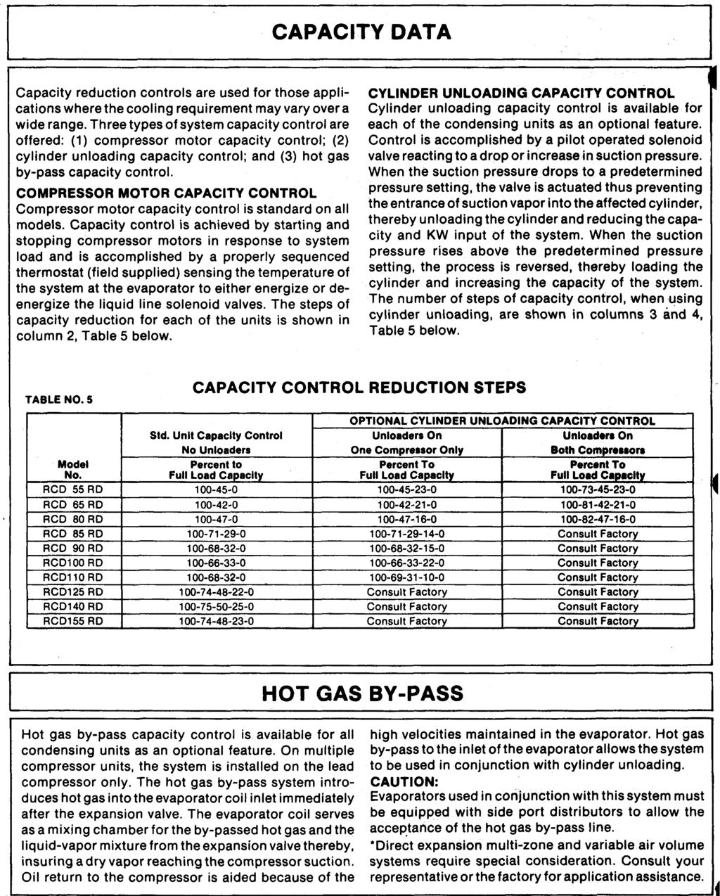
5 OPTIONAL ACCESSORIES For applications where close control is necessary, capacity reduction is accomplished by unloading cylinders on various compressors. (Refer to Page 18 for detailed capacity control information). HOT GAS BYPASS CAPACITY CONTROL Provides components on condensing unit to allow hot gas bypass line to be field piped to inlet of evaporator coil. Permits system operation down to 10% of full load. Hot gas bypass is provided on the first refrigerant circuit only. Factory installed components include the hot gas bypass valve and the hot gas solenoid valve. PRESSURE GAUGES Two inch suction and discharge pressure gauges are provided for each refrigerant circuit and two inch oil pressure gauge is provided for each compressor. Each gauge is furnished with its own shut-off valve. Factory installation includes mounting and piping to the compressors. HEATED RECEIVER LOW AMBIENT CONTROL TO 0 F. Utilizes heated and insulated oversized receivers in conjunction with standard fan cycling controls to assure compressor motor start in ambient temperature down to 0 F. Each heated receiver is equipped with a spring loaded relief valve, pressure control, thermostat and check valve. (Refer to Page 20 for detailed explanation). LIMITIZER LOW AMBIENT CONTROL TO -20 F. Utilizes refrigerant pressure activated modulating valves in conjunction with standard fan cycling controls to assure unit operation and compressor start down to -20 F. (Refer to Page 20 for detailed explanation). FIVE MINUTE LOCKOUT TIMER A five minute, solid state timer delays compressor restart for five minutes after a power interruption. PART WINDING START I For applications where current inrush is limited. Provides two step starting for each compressor motor. SAFETY CONTROLS ALARM CONTACTS Allows 115 volt alarm connection to alt safety controls, except pumpdown controls for signaling if unit fails on safety cut out. INSULATED COMPRESSOR ENCLOSURE Compressor compartment is lined with one inch, 1½ pound density glass, fiber, insulated panels for lower compressor section are furnished for models RCD 85 thru RCD 155. CIRCUIT BREAKERS Companion trip, ambient calibrated circuit breakers with builtin three leg overload protection provides additional protection for compressors. PHASE LOSS MONITOR Protects against phase loss (single phasing), phase reversal (improper phase sequence), and low voltage. Field adjustable for low voltage set point. CONTROL CIRCUIT TRANSFORMER A factory mounted and wired control circuit transformer is furnished eliminating the need for running a separate 115 volt power line for the unit control circuit. An optional transformer reduces line voltage to the 115 volts required. 5

6 RATINGS & SELECTION The ratings shown in Capacity Data Tables 1 and Capacity Charts 1 thru 11 are based on unit operation in a well designed and properly piped system. SELECTION RULES 1. Capacities are based on Refrigerant Ratings may be interpolated but must not be extrapolated. 3. Ratings shown are at saturated suction temperatures corresponding to pressures at the compressor. In actual practice, suction line pressure drop has the effect of reducing compressor capacity, forcing the compressor to operate at a lower suction pressure to maintain the desired evaporator temperature. 4. Ratings are for 60 Hertz operation. For 50 Hertz operation, multiply capacity by.87 and KW by.84. For normal air conditioning applications, size the suction line for a pressure drop of 3 PSI, corresponding to 2 F., for R-22 refrigerant. Thus. the evaporator temperature will be approximately 2 F.. higher than the compressor suction temperature. Line toss must be taken into consideration when selecting the evaporator. SELECTION PROCEDURE The Air Cooled Condensing Unit may be selected from Capacity Data Tables 1 (Page 7) or from the Capacity Charts 1 thru 10 if the ambient air temperature at the condenser and saturated suction temperature at the compressor are known. The ambient air temperature is a known design parameter, but the suction temperature at the compressor, in many cases, is known only within certain allowable limits. The actual compressor operating suction temperature and the overall performance of the system will depend directly upon the choice of the evaporator. Starting with a preliminary evaporator selection at a nominal evaporating temperature, using data supplied by the evaporator manufacturer, enter Capacity Data Table 1 or 2, and select a unit to meet the required cooling load at a suction temperature, at least 2 F. below the evaporator temperature. The 2 F., allows for normal suction line loss. If a more accurate selection is required, the evaporator capacity should be plotted against the condensing unit capacity to determine the balanced system performance. Again, it is necessary to factor in the suction line loss. After the system balance point has been determined, the compressor KW input may be interpolated from Capacity Data Table 1 or 2. SAMPLE SELECTION (Model RCD-55 matched with Model HCS Central Station Unit) Given: 1. Model HCS36 with a 5DE large face area DX coil (36.13 sq. ft.), CFM (500 FPM) and 80 F. DB/67 F. W air entering coil. 2. Total required cooling load: 600 MBH 3. Ambient air temperature: 95 F. 4. Evaporator temperature at the coil: 40 F. to 45 F. Find: Model RCD condensing unit and evaporator coil selection that will result in a balanced system and meet design requirements. Solution: 1. From Capacity Data Table 1, Model RCD55 has the capacity to meet the design load requirement when operating at a 95 F. ambient temperature and at a 40 F. saturated suction temperature at the compressor. 2. Make a preliminary coil selection at two arbitrary coil evaporator temperatures. From the Type 5. Direct Expansion Coil Catalog Bulletin 3302, Page 9, a sq. ft. 5DE4B coil will deliver 679 MBH at entering conditions of 80 D8/67 WB, 40 P. suction temperature at 500 FPM face velocity (18.8 MBH/sq. ft. x 36.13). The same coil at 45 F. suction temperature will deliver 556 MBH (15.4MBH/sq. ft. x36.13). 3. Enter the above coil capacities on Model RCD 55 unit curve at the appropriate suction temperatures as shown in the sample curve below. By joining the two points, "A" and "B"), the Coil Capcity Line is established. 4. To take the suction line loss into consideration, move horizontally left 2 F. from points "A" and "B" and draw a line parallel to the Coil Capacity Line (Points "D" and "C"). This establishes the System Capacity Line. 5. From the System Capacity Line determine the balanced conditions, as follows: (a) From the intersection of the System Capacity Line and 95 F. ambient temperature line (Point E) read left to find a balanced capacity of MBH. (b) From intersection Point E, read downward to find a saturated suction temperature of 40.7 F. at the compressor. (c) From the intersection at Point F, read downward to find an evaporator temperature of 42.7 F. at the coil. 6. Using the Capacity Data Table and interpolating between 40 F. and 45 F. suction temperature, the compressor KW input at 41 SST is From Condenser Fan Motor KW Input, Table 2, the condenser fans have a KW input of 8.8. The total unit KW input at full operating conditions would be

7 CAPACITY DATA MBH TABLE 1 7

8 CAPACITY DATA CHART NO. 1 CHART NO. 2 8


9 CAPACITY DATA CHART NO. 3 CHART NO. 4 9


10 CAPACITY DATA CHART NO. 5 CHART NO. 6 10

11 CAPACITY DATA CHART NO. 7 RCD110RD 1 1

12 CAPACITY DATA CHART NO. 8 RCD 125RD 12

13 CAPACITY DATA CHART NO. 9 RCD 140RD 13

14 CAPACITY DATA CHART NO. 10 RCD 155 RD 14
15 15
16 16
17 17
18 18
19 19
20 Due to the wide range of applications, it is sometimes necessary to operate the Air Cooled Condensing Units at ambients below summer conditions. Without proper control, when ambients drop below 60 F. the pressure differential between the condenser and the evaporator WINTER OPERATION is below the level to insure proper thermal expansion valve operation. As a result, the unit may cycle on low pressure control with the possibility of evaporator freezing. Three types of system control are offered allowing the units to operate at the winter indicated: FAN CYCLING HEAD PRESSURE CONTROL TO +30 F. AMBIENT (FACTORY EQUIPMENT FACTORY INSTALLED) A fan cycling control is standard on all Air Cooled Condensing Units to provide proper operating head pressures, in ambient conditions from +30 F. to 115 F. All fans on each unit are connected directly to the load Heated receivers are used in conjunction with the fan cycling control to assure compressor start in ambient temperatures down to 0 F, is offered as an optional priced feature. This, also, is an automatic operation and is accomplished by a pressure cycling control (set to cut in at 180 PSI and set to cut out at 210 PSI), sensing the receiver pressure and controlling a heater rod which has been immersed in a well built into the insulated receiver. A check valve, factory installed, in the refrigerant circuit between the receiver and the condenser prevents refrigerant migration from receiver to condenser during the off cycle. When the receiver pressure drops below 180 PSI, as would be encountered on the off cycle at low ambient conditions, the pressure switch would close and the receiver heater would be energized. With FAN CYCLING & HEATED RECEIVERS LOW AMBIENT CONTROL 0 F. (OPTIONAL EQUIPMENT FACTORY INSTALLED) side of each fan contactor, which in turn is controlled by the operation of the fan cycling pressure controls. This arrangement provides positive start-up control down to +30 F. by delaying the condenser fan operation until a predetermined head Pressure is obtained. the refrigerant flow blocked from receiver to condenser by the check valve and prevented from flowing from receiver to evaporator by the liquid line solenoid valve, receiver pressure would rise and be maintained sufficiently to allow expansion valve operation when the unit starts. If at any time, the receiver pressure would rise to 210 PSI the pressure control would open and the receiver heater would be de-energized. A back-up safety thermostat is provided to shut off the heater in the event the receiver temperature reaches 130 F. Once the unit has started, head pressure would be maintained by the fan cycling controls as explained under heading "Fan Cycling Head Pressure Control" above. LIMITIZER HEAD PRESSURE CONTROL TO -20 F. AMBIENT (OPTIONAL EQUIPMENT FACTORY INSTALLED) I The limitizer is a constant pressure regulating valve which is sensitive to the pressure in the condenser. When the condenser pressure is above the valve setting, as encountered during summer operation, the valve remains in the full open position and the system operates as if the valve were not installed in the line. As the ambient temperature drops, and the head pressure falls below the setting of the valve, the limitizer valve modulates toward the closed position, thus restricting the flow of liquid from the condenser. As a result of this restriction, liquid backs up in the condenser and floods a portion of the condenser tubes. The flooded tubes are then no longer effective as a condenser and the overall capacity of the condenser is reduced. The limitizer valve will modulate so as to cause sufficient flooding of the condenser to maintain the condenser pressure at the valve setting. Thus the limitizer system insures sufficient receiver pressure to maintain proper system operation at all times. At a 50 F. ambient temperature, approximately 50% of the condenser will be filled with liquid and at 0" F. approximately 90% of the condenser will be filled. The limitizer system also incorporates a bypass line installed between the hot gas discharge line and the downstream side of the limitizer valve. A bypass valve is installed in this line. During start-up, a sufficient quantity of hot gas will bypass directly to the receiver to prevent compressor short cycling. When this condenser is flooded, hot gas flowing through the bypass line reheats the liquid flowing from the condenser, thus maintaining a proper receiver pressure of approximately 170 PSIG. The limitizer system is completely automatic and does not require field adjustment. 20


21 REFRIGERANT PIPING TYPICAL PIPING DIAGRAM RECOMMENDED LINE SIZES TABLE NO. 5 NOTES: 1. Capacity based on 40 F. saturated suction temp. and 95 F. ambient air temperature. 2. Suction line selections based on 3 PSI (2 F.) pressure drop maximum per 100 ft. and velocities between 1,000 and 3,000 CFM. 3. Double suction risers are recommended for applications with units having optional additional capacity reduction. 4. Liquid line selections are based on 3 PSI (1 F.) pressure drop maximum per 100 ft. and maximum velocities of 300 FPM. 5. Refer to installation and operating instructions furnished with the unit for more detailed piping information. 21

22 ELECTRICAL DATA TYPICAL CONTROL WIRING MODELS RCD 55 THRU 80 RD /460 VOLTS DIAGRAM NO. 1 22
23 OPERATION The following sequence of operation is typical for a two circuit mode! RCD air cooled condensing unit. Controlled by a field supplied, remote two-stage thermostat nad liquid line solenoids. The sequence may vary between unit sizes, depending upon the number of compressor motors. For normal system operation, the field supplied two-stage thermostat must be in the "auto" position. With the main disconnect switch closed, power will be distributed to the control circuit through control circuit transformer, "TFI", (main power wiring diagram), thereby reducing the control voltage to 115 volts. Contacts 7 and 1 of crankcase heater relays "RT" and "RB" are closed (lines 2 and 3). energizing crankcase heaters "CCH1" and "CCH2" (lines 2 and 3). (Note: Crankcase heaters must be energized and remain active a minimum of 24 hours prior to system start up). Referring to Diagram No. 1, with the two-stage thermostat set in "auto" position, an electrical circuit is made across terminals 14 and 12 of terminal strip, "TER5", (lines 40 and 42) in the condensing unit control panel and through the holding coil of the evaporator fan starter. Placing control circuit switch, "SW1" (line 13). in the "on" position, energizes the balance of the control circuit and the system will operate on the demands of the space thermostat. When Stage 1 of the thermostat closes on cooling demand, an electrical circuit is established through the evaporator fan starter auxiliary contacts and staging relay. "R1". (line 43) If safety switches, "HP1", "OP1", and motor protector contacts "CMP1". (lines 17 and 18) are closed, the liquid line solenoid (field supplied) is energised permitting liquid refrigerant to flow to the low side of the system causing She suction pressure to increase. When the suction pressure reaches the "cut-in" setting o! the Pumpdown control, "PD1", (line 18), the switch closes, energizing compressor motor contactor. "C1", (line 19). Normally closed contacts 7 and 1 of crankcase heater relay "R7" (line 2) open, de-energizing the crankcase heater on compressor number 1. Simultaneously, when compressor motor contactor "C1" is energized, the contactor "C9" (line 22) will close when the high side pressure reaches the "cut-in" setting of the fan cycling pressure control. "FCP1" (main power wiring diagram) the condenser fan motors will start. (Note: Each condenser fan motor is controlled by a fan cycling pressure control if the high side pressure falls below the setting of hte individual tan cycling control the respective fan motor will cycle off). On a further demand for cooling, Stage 2 of the thermostat will close After a 15 second time delay through stage start timer, "TD13" (line 47). compressor circuit number 2 will be activated in the same sequence as outlined for compressor circuit number 1. Pumpdown Cycle As the cooling demand decreases. Stage 2 of the thermostat will open, deenergizing staging relay "R2" (line 49) and the liquid line solenoid, thereby stopping the refrigerant (low to the low side of the system. Compressor No. 2 will continue to run until the suction pressure reaches the "cut-out" setting of Pumpdown control, "PD2" (line 32). The Pumpdown switch opens de-energizing compressor motor contactor, "C3" (line 33), causing compressor motor number 2 to cycle off. Contacts 7 and 1 of crankcase heater relay, "R8" (line 3) will close, thereby energizing compressor crankcase heater "CCH2". Contactor "C10" de-energizes stopping the fan motor controlled by "C10" (line 36). A further reduction in cooling demand will cause Stage 1 of the thermostat to open and circuit number 1 will pumpdown in the same sequence as outlined for circuit number 2. (Note: The condensing unit is set up for automatic pumpdown operation. If for any reason the suction pressure on either refrigerant circuit should increase to the "cut-in" setting of pumpdown controls, "PD1" or "PD2" (lines 18 and 32). the pumpdown cycle will be activated). The condenser fans will cycle oft when the last compressor motor stops or when the high side pressure drops below the "cut-out" settings of the fan cycling pressure controls (main power diagram) whichever occurs first Sately Controls Each refrigerant circuit is protected by safety controls for high pressure and oil pressure in addition to a compressor motor thermal protector HP1, OP1, and CMP1 (line 18) on circuit number 1, and HP2, OP2, and CMP2 (line 32) on circuit 2- If any of these devices should open due to abnormal conditions, the compressor in the associated circuit will automatically stop The motor protectors CMP1 and CMP2 are automatic reset. 1 the safety switches HP1-2 and OP1-2 must be manually reset. ELECTRICAL OPTION ACCESSORIES Cylinder Unloading Capacity Control Unloading is activated through pressure control. "CP1" and "CP2". As the suction pressure drops below the setting of the capacity pressure control the un loader solenoid. (UL 1 -UL2), mounted on the compressor head, is energized, thereby preventing the entrance of suction vapor into the unloaded cylinders, thus reducing system capacity. As the suction pressure rises above the setting of the capacity pressure control, the unloader solenoid is deenergized, thereby loading the cylinders and increasing system capacity. Part Winding Start Referring to circuit number 1. time delay relay. "TDI" is wired in series with compressor motor contactor."c2" and delays the closing of contactor. "C2" for one second after compressor motor contactor "C1" is energized Part Winding Start for circuit number 2 operates identical to circuit number 1 (not available for 575/3/60 electrical characteristics applications). Five Minute Lockout Timer Time delay relay "TD5" prevents unit from starting for five minutes after power has been supplied to the main disconnect switch. Safety Controls Alarm Contacts Terminals 6 thru 9 of terminal board, "TER5". provide means to connect a remote alarm device to signal the failure of high pressure and/or oil pressure controls. (Alarm device and remote wiring are not included). 23
24 INSTALLATION & APPLICATION DATA LOCATION & SPACE REQUIREMENTS Model RCD air cooled condensing units are designed for outdoor application and may be mounted on a roof or at ground level. Air flow through the condenser is vertical and the unit may be located adjacent to the outside of a building or on the roof without regard for prevailing wind direction. Since these units are air cooled, the flow of air to and from the condenser coil must not be impeded. There must be no obstruction above the unit that would deflect the discharge air downward where it could be recirculated back to the inlet of the unit. The minimum overhead air space should be 8 feet. Ductwork must not be applied to the fan outlet. The unit must be installed with sufficient clearance for air entrance to the condenser coil and for servicing access. The unit should be located no closer than one fan diameter from any wall or other obstruction. Ten feet should be allowed between adjacent units on multiple condensing unit installations. FOUNDATION Unit should be set on a solid and level foundation: ROOF MOUNTED Unit should be installed on steel channel or I-beam frame to support the unit above the roof. GROUND LEVEL Unit should be installed on a substantial base that will not settle. A one piece concrete slab with footings extended below the frost line is recommended. VIBRATION ISOLATION Vibration mounts may be used for roof mounted units or other locations where noise might be objectionable (adjacent to occupied spaces such as meeting rooms, offices, etc.) REFRIGERANT PIPING Careful design of refrigerant piping is necessary for proper system operation. The refrigerant piping generally should be designed to accomplish the following: 1. To assure proper refrigerant feed to the evaporator. 2. To provide practical refrigerant line sizes without excessive pressure drop. 3. To maintain uniform return of lubricating oil to the compressor. 4. To prevent refrigerant from entering the compressor causing damage from slugging. General Limit the length of refrigerant piping by locating the condensing unit as close to the evaporator as possible. On two refrigerant circuit models, separate evaporator circuits must be selected to balance with the individual condensing unit circuits. Liquid Lines Standard practice is to size liquid lines for 1 change in saturation temperature which corresponds to approximately 2.9 psi pressure drop. Filter-Drier To minimize the possibility of system failure due to dirt and moisture, a replaceable element filter-drier must be furnished and installed in the field. A moisture indicator and sight glass should be installed between the filter-drier and expansion valve to aid in maintaining the system. Suction Lines Standard practice is to size suction lines for 2 F. change in saturation temperature which corresponds to approximately 2.93 psi pressure drop. Maximum saturated suction gas temperature is 50 F. at any condensing temperature. Insulation Suction lines should be insulated, especially where exposed to high ambient temperature. DIRECT EXPANSION MULTI-ZONE OR VARIABLE AIR VOLUME SYSTEMS Air cooled condensing units to be used in conjunction with multi-zone or variable air volume systems require special consideration. Contact the Applications Department at the factory for application recommendations. 24
25 DIRECT EXPANSION VARIABLE AIR VOLUME SYSTEMS The Direct Expansion Variable Air Volume System is increasing in popularity due to the economies of reduced air flow in air conditioning applications. In a V.A.V. System, the refrigeration capacity is usually modulated by a controller sensing supply air temperature. This arrangement combined with variable airflow across the evaporator coil. requires special considerations when applying the condensing unit and circuiting the coil. Modifications, necessary to assure proper operation of the condensing unit, should include the following: 1. Maximum cylinder unloading steps. 2. Electrical unloading rather than suction pressure unloading, 3. Hot gas by-pass capacity reduction (to the evaporator). 4. A discharge sensing step controller (similar to Honeywell Model W7100). These modifications, when properly applied, wilt prevent condensing unit compressor(s) short cycling and assure system operation under light load conditions. Another important factor to be considered in Direct Expansion V.A.V. Systems is the circuiting of air handling unit's evaporator coil. An evaporator with two refrigerant circuits should not be face split. A "Ther-mobtend" circuiting, with a fully active fin surface throughout all steps of operation, is recommended. It is also important that the evaporator circuits and loads be selected to match each circuit of the condensing unit. 25
26 ENGINEERING GUIDE SPECIFICATIONS GENERAL Furnish and install where on plans Model RCD... air cooled condensing unit or approved equal. Units are assembled as a single package on one base as follows: Heavy gauge mounting frame, supported by six heavy gauge galvanized steel legs and two steel skids with corrosion resistant finish. Lifting holes are provided to facilitate unit rigging. CASING The casing shall be constructed of 12 gauge (.080) aluminum, thoroughly reinforced with bolted gussets of aluminum and galvanized steel. Casing shall be divided by full width aluminum baffles that separate the individual fan sections and provide additional casing reinforcement. CONDENSER COIL The condenser coil shall be constructed of ½" 0.0. copper tube with plate type, die formed aluminum fins. The fins shall have full self-spacing collars which completely cover the copper tube. The fins shall be mechanically bonded to the copper tubes. The condenser coil shall be divided into two circuits with each circuit balanced to its compressor(s). SUB-COOLING COIL A separate sub-cooling coil, integral with the main condenser coil, shall be provided for each refrigerant circuit. CONDENSER FANS The fan section shall be furnished with propeller fans arranged for vertical air discharge- The I fan section shall be divided by full width aluminum baffles to prevent air by-pass. The fans shall be stati-cally and dynamically balanced and shall be individually driven by separate fan motors. Each fan outlet shall be spun to provide maximum efficiency, eliminate fan panel vibration and reduce noise. Each fan shall be protected by a heavy gauge, close mesh fan guard. I CONDENSER FAN MOTORS I The condenser fan motors shall be as follows: All models hall have inherently protected direct drive, eight pole, three phase _ RPM motors with perman- ently grease lubricated ball bearings. The motors shall I be located within the unit casing for weather protec- tion and shall be mounted on an adjustable base to allow belt tension adjustment. Each motor and fan bearing shall be easily accessible through access panels located in the unit casing. COMPRESSOR Compressor shall be of the accessible hermetic type with suction and discharge service valves, crankcase heater, oil sight glass and oil charging connection. Compressors shall have force feed lubrication system with reversible oil pump and operating oil charge. Compressor motors shall be high torque, hermetic induction type _ RPM with inherent thermal protection for volt, Hertz, phase, electrical service. Compressor(s) shall be mounted on vibration absorbing mounts. LIQUID SEAL LOOP A sub-cooling liquid seal loop shall be provided for each refrigerant circuit. The condenser coil and liquid accumulators shall have storage capacity to accomplish normal system pumpdown. The liquid seal loop shall be U.L. listed and shall include a fusible plug relief. CONTROL CENTER A fully enclosed and weatherproofed control panel with tool operated lock access doors shall be furnished. Dual compartments shall separate the safety and operating controls from the power controls. Control center shall include system off-on switch, compressor motors contactors fan motors contactors, compressor motors overcurrent protection, fan motors circuit breaker, high pressure controls, oil pressure controls, pumpdown pressure controls, fan cycling controls, power terminal block, control circuit terminal board and low side interlock terminal board. Multiple compressor motor units shall have sequenced motor start time delay relays. LOW AMBIENT CONTROL Unit shall be provided with automatic head pressure control by cycling condenser fans in response to pressure to maintain head pressure to +30 F, ambient. REFRIGERANT PIPING Each refrigerant circuit shall include, suction line strainer, manual liquid line shut-off valve and charging connection. FACTORY TEST Each unit shall be evacuated, leak tested, electrical tested and shipped with a holding charge of R-22. Manufacturer reserves the right to discontinue, or change specifications, or change designs without notice and without incurring obligation 26
TECHNICAL GUIDE DESCRIPTION SPLIT-SYSTEM AIR-COOLED CONDENSING UNITS MODELS: HF-07 FEATURES B-0703
 TECHNICAL GUIDE SPLIT-SYSTEM AIR-COOLED CONDENSING UNITS MODELS: HF-07 DESCRIPTION These Sunline 2000 units are completely assembled, piped and wired at the factory to provide one-piece shipment and rigging.
Catalog Air Cooled Split System Condensing Units for Rooftop Systems and Air Handlers
 Air Cooled Split System Condensing Units for Rooftop Systems and Air Handlers Models RCS 025C through 135C 25 to 135 Tons R-22/R407C Refrigerant Catalog 221-1 Table of Contents Introduction.... 3 The Condensing
Air-Cooled Split System Condensing Unit for Rooftop Systems and Air Handlers
 Catalog 221-1 Air-Cooled Split System Condensing Unit for Rooftop Systems and Air Handlers Model RCS 025C to 135C R-22/R-407C Refrigerant Contents Introduction............................... 3 The Condensing
AIR COOLED PACKAGED CHILLER
 AIR COOLED PACKAGED CHILLER UNIC sal is equipped to produce a wide range of COOLER Air conditioning and Refrigeration units, conforming to the international standards and works continually to improve its
PACKAGE AIR CONDITIONER
 PACKAGE AIR CONDITIONER FORM NO. ATZ-206 TZAA- HIGH EFFICIENCY SERIES NOMINAL SIZE 10 TON [35.2 kw] 10 TON MODEL [35.2 kw] This product is shipped with a nitrogen holding charge that must be vented prior
TECHNICAL GUIDE. Description SPLIT-SYSTEM AIR-COOLED CONDENSING UNITS YD360, 480 & THRU 50 NOMINAL TONS YTG-B-0811
 Description These units are completely assembled, piped and wired at the factory to provide one-piece shipment and rigging. Each unit is pressurized with a holding charge of Refrigerant R-410A for storage
Product Data. Features/Benefits. GEMINI 38AKS Commercial Air-Cooled Split Systems 50/60 Hz. 25 to 40 Nominal Tons (82.8 to 127.
 Product Data GEMINI 38AKS028-044 Commercial Air-Cooled Split Systems 50/60 Hz 25 to 40 Nominal Tons (82.8 to 127.0 kw) These dependable split systems match Carrier s indoor-air handlers with outdoor condensing
SECTION AIR-COOLED SPLIT SYSTEM AIR CONDITIONING UNITS
 SECTION 23 62 13 - AIR-COOLED SPLIT SYSTEM AIR CONDITIONING UNITS PART 1 - GENERAL 1.1 RELATED DOCUMENTS: A. The Conditions of the Contract and applicable requirements of Division 1, "General Requirements",
Installation, Operation, and Maintenance Information
 Installation, Operation, and Maintenance Information Air Cooled Condensers 8-2016 Rev 0 Table of Contents General Safety Information 2 Inspection 2 Installation 2 6 Rigging and Assembly 2 Unit Location
30GT FLOTRONIC AIR-COOLED CHILLERS
 30GT-41SB 30GT040-110 FLOTRONIC AIR-COOLED CHILLERS PERFORMANCE DATA FIELD WIRING DIAGRAM 1998 Carrier Corporation Syracuse, New York 13221 Form 30GT-41SB Supersedes 30GT-21SB, 30GT-22SB, 30GT-23SB, Printed
CAS. Product Specifications. COMMERCIAL SPLIT SYSTEMS CONDENSING UNITS R 410A, 6 to 12.5 TONS BUILT TO LAST, EASY TO INSTALL AND SERVICE
 COMMERCIAL SPLIT SYSTEMS CONDENSING UNITS R 410A, 6 to 12.5 TONS BUILT TO LAST, EASY TO INSTALL AND SERVICE CAS Product Specifications Single stage cooling capacity control on all models with Micro channel
Commercial High-Efficiency Condensing Units
 FORM NO. A22-193 REV. 3 Supersedes Form No. A22-193 Rev. 2 Commercial High-Efficiency Condensing Units 15 & 20 TON MODEL [52.8 & 70.3 kw] 10 & 12.5 TON MODEL [35.2 & 44.0 kw] 10 THROUGH 20 NOMINAL TON
30GN FLOTRONIC II AIR-COOLED CHILLERS
 30GN-19SB 30GN040-110 FLOTRONIC II AIR-COOLED CHILLERS PERFORMANCE DATA FIELD WIRING DIAGRAM 1998 Carrier Corporation Syracuse, New York 13221 Form 30GN-19SB Supersedes 30GN-6SB, 30GN-7SB, 30GN-8SB, Printed
INTRODUCTION. Special Applications of Package Air Conditioners. Instant Cooling Requirement in Wedding Ceremonies
 Pakistan s Largest Manufacturers of Air-Conditioners PACKAGE TYPE UNIT FOR MOBILE APPLICATIONS Provides Turnkey Projects Conceptual Planning to Commissioning of HVACR Projects THE LARGEST MANUFACTURER
Microchannel REMOTE AIR COOLED CONDENSER. Technical Bulletin: MXCC_004_ Products that provide lasting solutions.
 Microchannel REMOTE AIR COOLED CONDENSER Technical Bulletin: MXCC_004_030817 Products that provide lasting solutions. Krack s new Microchannel Remote Air Cooled Condenser incorporates a new patented modular
MACH N-407 Heat Pump Air-Cooled Chiller
 MACH060-01-N-407 Heat Pump Air-Cooled Chiller Heat Pump Air-Cooled Chillers for Global Residential and Light Commercial Microclimates MACH NOMENCLATURE BREAKDOWN MACH-060-01 - N - 407 Refrigerant Type
Product Data PH13(N,P)R FEATURES AND BENEFITS. SPLIT SYSTEM HEAT PUMP For Use With R Refrigerant 1---1/2 TO 5 TONS ( )
R FEATURES AND BENEFITS. SPLIT SYSTEM HEAT PUMP For Use With R Refrigerant 1---1/2 TO 5 TONS ( )") (N,P)R SPLIT SYSTEM HEAT PUMP For Use With R --- 22 Refrigerant 1---1/2 TO 5 TONS (018 --- 060) Product Data *Units factory---shipped with no refrigerant. Dry nitrogen charge only. FEATURES AND BENEFITS
(N,P)R SPLIT SYSTEM HEAT PUMP For Use With R --- 22 Refrigerant 1---1/2 TO 5 TONS (018 --- 060) Product Data *Units factory---shipped with no refrigerant. Dry nitrogen charge only. FEATURES AND BENEFITS
T-SERIES SPLIT SYSTEM UNITS R-410A - 60 HZ. EER up to to 20 Tons Cooling Capacity - 71,000 to 236,000 Btuh AIR CONDITIONERS TS
 PRODUCT SPECIFICATIONS CONDITIONERS TS T-SERIES SPLIT SYSTEM UNITS R-410A - 60 HZ Bulletin No. TSA-072-240 (11/2016) 072-090 Models 180-240 Models 120-150 Models EER up to 11.7 6 to 20 Tons Cooling Capacity
B. Unit construction shall comply with ASHRAE 15 Safety Code, NEC, and ASME applicable codes (U.S.A. codes).
.") Guide Specifications PART 1 GENERAL 1.01 SYSTEM DESCRIPTION Microprocessor controlled, air-cooled liquid chiller utilizing scroll compressors, low sound fans, hydronic pump system and optional fluid storage
Guide Specifications PART 1 GENERAL 1.01 SYSTEM DESCRIPTION Microprocessor controlled, air-cooled liquid chiller utilizing scroll compressors, low sound fans, hydronic pump system and optional fluid storage
Air-Cooled Condensers
 Catalog Cat 622-2 Air-Cooled Condensers Model ACH 014-225 Model ACX 014-225 Model ACL 014-225 Capacities from 130 MBH to 2225 MBH R-134a, R-407c, R-410A Table of Contents Introduction...3 Model Description...4
Product Chillers A P P L I C AT I O N S
 Product Chillers A P P L I C AT I O N S Wineries Bottling Product Storage Product Ripening Meat Processing Florist Boxes Packaging Rooms Walk-in Coolers Beverage Boxes CENTURY PRODUCT CHILLERS Unit Configuration
Condensing Unit Installation and Operating Instructions
 Bulletin WCU_O&I 01 June 2003 Condensing Unit Installation and Operating Instructions WCU Air Cooled Condensing Unit Table of Contents Section 1. Section 2. Section 3. Section 4. Section 5. Section 6.
Liebert CSU3000 Chiller
 CSI 15620 - Packaged Water Chillers Liebert CSU3000 Chiller Guide Specifications for 7.5-37 Ton CS/CD/CT Models 1.0 GENERAL 1.1 CS/CD MODELS The main-frame coolant supply unit shall be a Liebert Model,
PAJ3. Product Specifications
 13 SEER, R 410A PACKAGE AIR CONDITIONER FOR MANUFACTURED HOUSING, RESIDENTIAL, AND LIGHT COMMERCIAL APPLICATIONS 2 5 TONS Single Phase, 208/230 V, 60 Hz BUILT TO LAST, EASY TO INSTALL AND SERVICE Compact,
MIN. CCT. QTY RLA LRA HP FLA AMPACITY /1/ /3/
 1 of 3 Cooling Capacity [Btuh] 24,800 * Condensing Unit SEER: 13.0 ** Condensing Unit CFM: 1,600 Condenser Fan No./Type: 1/CENTRIFUGAL Diameter x Width [in]: 10x10 Drive: Adjustable Belt Motor HP: 0.5
DRY CHARGE UNITS. 1.5 to 5 Tons AIR CONDITIONERS LCS13DC PRODUCT SPECIFICATIONS L C S 13 DC MODEL NUMBER IDENTIFICATION
 CONDITIONERS DRY CHARGE UNITS PRODUCT SPECIFICATIONS Bulletin No. 20636 May 204 Supersedes March 202.5 to 5 Tons MODEL NUMBER IDENTIFICATION L C S 3 DC - 036-230 - 2 Lennox Minor Revision Number Air Conditioner
T P A 120 S 4 S N 1 Y
 PRODUCT SPECIFICATIONS HEAT PUMP OUTDOOR UNITS TP T-SERIES SPLIT SYSTEM UNITS R-410A - 60 HZ Bulletin No. TPA-090-120 (11/2012) EER up to 11.0 7.5 to 10 Tons Cooling Capacity - 89,000 to 180,000 Btuh Heating
C. ASME Compliance: Fabricate and label water chiller heat exchangers to comply with ASME Boiler and Pressure Vessel Code: Section VIII, Division 1.
 SECTION 236426 - ROTARY-SCREW WATER CHILLERS PART 1 - GENERAL 1.1 SUMMARY A. This Section includes packaged, water cooled or air cooled as scheduled, electric-motor-driven, rotary-screw water chillers
1.1 This section applies to air handling units for HVAC Systems.
 AIR HANDLING UNITS GENERAL INFORMATION 1.1 This section applies to air handling units for HVAC Systems. DESIGN REQUIREMENTS 2.1 Design Criteria a. The decision to use modular central station air handling
SECTION AIR COOLED WATER CHILLERS
 PART 1 GENERAL 1.1 SECTION INCLUDES A. Chiller package B. Charge of refrigerant and oil C. Controls and control connections D. Chilled water connections E. Starters F. Electrical power connections 1.2
MAC-120HE-03 Air-Cooled Chiller
 MAC-120HE-03 Air-Cooled Chiller 10 Ton / 120,000 BTUH Air-Cooled Chiller 380/415/460-3-50/60 1 HVAC Guide Specifications Air-Cooled Liquid Chiller Nominal Size: 10 Tons Multiaqua Model Number: MAC-120HE-03
UP to 14.5 SEER, PACKAGE AIR CONDITIONER UNIT, 2 to 5 TONS 208/230 Volt, 1 phase, 60 Hz REFRIGERATION CIRCUIT
 SOUND REFRIGERANT ENVIRONMENTALLY PAJ4 Product Specifications UP to 14.5 SEER, PACKAGE AIR CONDITIONER UNIT, 2 to 5 TONS 208/230 Volt, 1 phase, 60 Hz REFRIGERATION CIRCUIT Environmentally sound R-410A
TECHNICAL GUIDE DESCRIPTION SPLIT-SYSTEM AIR-COOLED CONDENSING UNITS. HA300, HB360, HB480 & HB thru 50 NOMINAL TONS (50 Hz)
") DESCRIPTION These units are completely assembled, piped and wired at the factory to provide one-piece shipment and rigging. Each unit is pressurized with a holding charge of refrigerant-22 for storage
DESCRIPTION These units are completely assembled, piped and wired at the factory to provide one-piece shipment and rigging. Each unit is pressurized with a holding charge of refrigerant-22 for storage
DTW Works Master Specification Version 2006 Issued 2006/08/01 Section15621 Packaged Reciprocating Water Chillers Page 1 of 5
 Issued 2006/08/01 Section15621 Packaged Reciprocating Water Chillers Page 1 of 5 PART 1 GENERAL 1.1 RELATED SECTIONS.1 Section 01330 Submittal Procedures..2 Section 01355 Waste Management and Disposal..3
3 to 5 Tons. AIR CONDITIONERS 2scu13. Dry Charge Split System - 60 HZ PRODUCT SPECIFICATIONS. 2 scu 13 lc 1 36 t - 1 a MODEL NUMBER IDENTIFICATION
 AIR CONDITIONERS 2scu3 PRODUCT SPECIFICATIONS Dry Charge Split System - 60 HZ Bulletin No. 20644 May 204 Supersedes September 203 3 to 5 Tons MODEL NUMBER IDENTIFICATION 2 scu 3 lc 36 t - a Refrigerant
TECHNICAL GUIDE GENERAL SPECIFICATIONS COMMERCIAL SPLIT-SYSTEM COOLING UNITS FOUR PIPE SYSTEM OUTDOOR UNIT: INDOOR UNIT:
 GENERAL SPECIFICATIONS OUTDOOR UNIT: TECHNICAL GUIDE COMMERCIAL SPLIT-SYSTEM COOLING UNITS FOUR PIPE SYSTEM MODELS HB 180 & HB 240 MODELS LB 180 & LB 240 15 & 20 NOMINAL TONS 9.7 EER Two independent refrigerant
DSV Model Air Cooled Self Contained Indoor Packaged Units 3-5 Tons Preliminary Application Data
 DSV Model Air Cooled Self Contained Indoor Packaged Units 3-5 Tons Preliminary Application Data July 28, 2008 Page 1 1 of 3 PROJECT: TAG: Gross Cooling Capacity [Btuh]: 37,800* Design CFM: 1,200 Seasonal
MAC N-407 Air-Cooled Chiller
 MAC036-01-N-407 Air-Cooled Chiller Air-Cooled Chillers for Global Residential and Light Commercial MicroClimates MAC036 NOMENCLATURE BREAKDOWN MAC036-01 - N - 407 Refrigerant Type Air-Cooled Chiller 036=
Product Data. Features/Benefits. 38AH Commercial Air-Cooled Condensing Units 50/60 Hz. 20 to 130 Nominal Tons (63 to 390 Nominal kw)
") Product Data 38AH024-134 Commercial Air-Cooled Condensing Units 50/60 Hz 20 to 130 Nominal Tons (63 to 390 Nominal kw) a38-4143ef 38AH044-134 These dependable split systems match Carrier s 40RM or 39 Series
Product Data 38AH024-134 Commercial Air-Cooled Condensing Units 50/60 Hz 20 to 130 Nominal Tons (63 to 390 Nominal kw) a38-4143ef 38AH044-134 These dependable split systems match Carrier s 40RM or 39 Series
Advance Release September 2009
 Vertical Air Cooled DSV Series R 410A Model DSV096 DSV120 DSV144 DSV180 Nominal Cooling (Tons) 8 10 12 15 Refrigerant R 410A R 410A R 410A R 410A Cooling Performance Gross Cooling Capacity(Btu/h) 95,000*
Commercial High-Efficiency Condensing Units
 FORM NO. A22-194 REV. 2 Supersedes Form No. A22-194 Rev. 1 Commercial High-Efficiency Condensing Units RAWL High Efficiency 6.5 & 7.5 TON MODEL [22.86 & 26.38 kw] TABLE OF CONTENTS Model Number Designation...2
TECHNICAL GUIDE MODELS: H5CE090, H3CE120 & H1CE /2, 10, & 12-1/2 NOMINAL TONS EER DESCRIPTION
 TECHNICAL GUIDE SPLIT-SYSTEM AIR-COOLED CONDENSING UNITS SUNLINE 2000ô MODELS: H5CE090, H3CE120 & H1CE150 7-1/2, 10, & 12-1/2 NOMINAL TONS 9.0-9.5 EER DESCRIPTION These Sunline 2000ô units are completely
Microchannel REMOTE AIR COOLED CONDENSER WITH ELECTRONICALLY COMMUTATED AXITOP MOTORS. Technical Bulletin. Products that provide lasting solutions.
 Microchannel REMOTE AIR COOLED CONDENSER WITH ELECTRONICALLY COMMUTATED AXITOP MOTORS Technical Bulletin Products that provide lasting solutions. Krack Corporation has a long tradition of leadership and
SECTION PACKAGED ROOFTOP AIR CONDITIONING UNITS
 SECTION 15732 - PACKAGED ROOFTOP AIR CONDITIONING UNITS PART 1 - GENERAL 1.1 SECTION INCLUDES A. Package roof top unit. B. Heat exchanger. C. Refrigeration components. D. Unit operating controls. E. Roof
Contour TM Screw Compressors
 Contour TM Screw Compressors Semi-Hermetic Compact Operating Instruction SCH1 High Temp Compressors Form No. 99-77 1. Introduction This series of semi-hermetic compact screw compressors is designed for
MERIT Series R-410A. SEER up to to 5 Tons Cooling Capacity - 17,500 to 59,000 Btuh AIR CONDITIONERS 13ACXN PRODUCT SPECIFICATIONS
 PRODUCT SPECIFICATIONS AIR CONDITIONERS 13ACXN MERIT Series R-410A Bulletin No. 210831 January 2018 Supersedes Bulletin No. 210739 SEER up to 15.50 1.5 to 5 Tons Cooling Capacity - 17,500 to 59,000 Btuh
072, 090, 120, 180 & 240 MODELS C SERIES CONDENSING UNITS P SERIES HEAT PUMPS
 072, 090, 120, 180 & 240 MODELS C SERIES P SERIES HEAT PUMPS SPLIT L SERIES SYSTEMS LSA Condensing Units 6 Thru 20 Ton (21.1 Thru 70.3 ) Heat Pumps 7.5 & 10 Ton (26.4 & 35.2 ) Bulletin #210164 February
Installation, Start-Up and Service Instructions
 38AH044-134 Air-Cooled Condensing Units 50/60 Hz Installation, Start-Up and Service Instructions CONTENTS Page SAFETY CONSIDERATIONS...................... 1 INSTALLATION................................
Nominal Capacity 024 = 7 kw (2 tons) 036 = 10.5 kw (3 tons) 048 = 14 kw (4 tons) 060 = 17.5 kw (5 tons)
 036 = 10.5 kw (3 tons) 048 = 14 kw (4 tons) 060 = 17.5 kw (5 tons)") ENGINEERING DATA HEAT PUMP OUTDOOR UNITS HP40 50HZ Capacity 6.2 to 16.3 (21 200 to 55 500 Btuh) Heating Capacity 6.4 to 16.1 (21 800 to 55 500 Btuh) Bulletin No. 490088 October 2004 Supersedes August 1999
ENGINEERING DATA HEAT PUMP OUTDOOR UNITS HP40 50HZ Capacity 6.2 to 16.3 (21 200 to 55 500 Btuh) Heating Capacity 6.4 to 16.1 (21 800 to 55 500 Btuh) Bulletin No. 490088 October 2004 Supersedes August 1999
SECTION ROTARY-SCREW WATER CHILLERS
 PART 1 GENERAL 1.01 SECTION INCLUDES A. Factory-assembled packaged chiller. B. Charge of refrigerant and oil. C. Controls and control connections. D. Chilled water connections. E. Electrical power connections.
C13-Series Engineering Guide
 Engineering Guide Effective January 2018 Horizontal Air-Cooled, Water-Cooled, Chilled Water and Heat Pump Contents Product Features............................... 3 Product Options................................
.2 Section Waste Management and Disposal.
 Issued 2005/06/01 Section 15624 Packaged Rotary Screw Water Chillers Page 1 of 5 PART 1 General 1.1 RELATED SECTIONS.1 Section 01330 Submittal Procedures..2 Section 01355 Waste Management and Disposal..3
Condensing Unit Installation and Operating Instructions
 Bulletin ACU_O&I 02 August 2016 Condensing Unit Installation and Operating Instructions ACU Air Cooled Condensers Table of Contents Section 1. General Information... 2 Section 2. Refrigeration Piping...
SECTION REFRIGERATION EQUIPMENT. A. Section Includes: Refrigeration equipment for insulated cold storage rooms including necessary accessories.
 SECTION 15650 REFRIGERATION EQUIPMENT PART 1 GENERAL 1.01 SUMMARY A. Section Includes: Refrigeration equipment for insulated cold storage rooms including necessary accessories. B. Related Section: 1. 11400
MAC-036HE-02-L High Efficiency Air-Cooled Chiller Air-Cooled Chillers for Global Residential and Light Commercial Micro Climates Rev 1.
 MAC-036HE-02-L High Efficiency Air-Cooled Chiller Air-Cooled Chillers for Global Residential and Light Commercial Micro Climates Rev 1.1 HVAC Guide Specifications Air-Cooled Liquid Chiller with Low Ambient
MAC-048HE-01-L High Efficiency Air-Cooled Chiller Air-Cooled Chillers for Global Residential and Light Commercial Micro Climates Rev 1.
 MAC-048HE-01-L High Efficiency Air-Cooled Chiller Air-Cooled Chillers for Global Residential and Light Commercial Micro Climates Rev 1.1 HVAC Guide Specifications Air-Cooled Liquid Chiller with Low Ambient
VERTICAL STACK INNKEEPER GUIDE SPECIFICATION CGC Hybrid Heat Pump System
 VERTICAL STACK INNKEEPER GUIDE SPECIFICATION CGC Hybrid Heat Pump System PART 1 SYSTEM DESCRIPTION 1.1 The HVAC system is based on the CGC HYBRID Hydronic Heat Pump System. 1.2 The system will automatically
SKYPAK II, 3 Ton Series, gives you a
 SKYPAK II 3 ton Heating And Cooling self-contained Package SKYPAK II, 3 Ton Series, gives you a complete air-conditioning and heating system as an all in one package unit. Designed for convenient through-the-wall
ELITE Series R-410A. SEER up to to 5 Tons Cooling Capacity - 17,800 to 60,000 Btuh AIR CONDITIONERS EL16XC1 PRODUCT SPECIFICATIONS
 PRODUCT SPECIFICATIONS AIR CONDITIONERS EL6XC ELITE Series R-40A Bulletin No. 20833 July 208 Supersedes March 208 SEER up to 7.90.5 to 5 Tons Cooling Capacity - 7,800 to 60,000 Btuh MODEL NUMBER IDENTIFICATION
MAC-060HE-01-L High Efficiency Air-Cooled Chiller Air-Cooled Chillers for Global Residential and Light Commercial Micro Climates Rev 1.
 MAC-060HE-01-L High Efficiency Air-Cooled Chiller Air-Cooled Chillers for Global Residential and Light Commercial Micro Climates Rev 1.2 HVAC Guide Specifications Air-Cooled Liquid Chiller with Low Ambient
Air-Cooled Split System Condensing Units for Remote DX Coils and Air Handlers. Models RCS 015D to 140D R-410A Refrigerant.
 Air-Cooled Split System Condensing Units for Remote DX Coils and Air Handlers Models RCS 015D to 140D R-410A Refrigerant Catalog 222-5 Introduction.... 3 The Condensing Unit for Applied Rooftop and Air
JCseries EVAPORATIVE CONDENSER. engineering data
 JCseries EVAPORATIVE CONDENSER engineering data Recold JC Series Evaporative Condenser Contents 2 Construction... 3 Schematic... 4 Engineering Data... 5 Selection Procedure... 6-9 Multi-Circuited Selection
SECTION WATER-SOURCE UNITARY HEAT PUMPS
 SECTION 23 81 46 WATER-SOURCE UNITARY HEAT PUMPS PART 1 - GENERAL 1.1 RELATED DOCUMENTS A. Drawings and general provisions of Contract, including General and Supplementary Conditions and Division 1 Specification
CS/CD/CP AIR COOLED CONDENSING UNITS (P/N E207120C R2)
") CS*/CD*/CP* Series Air Cooled Condensing Units Operating and Installation Manual CS/CD/CP AIR COOLED CONDENSING UNITS (P/N E207120C R2) TABLE OF CONTENTS I. Receipt of Equipment 2 II. Piping...4 III. System
CS*/CD*/CP* Series Air Cooled Condensing Units Operating and Installation Manual CS/CD/CP AIR COOLED CONDENSING UNITS (P/N E207120C R2) TABLE OF CONTENTS I. Receipt of Equipment 2 II. Piping...4 III. System
DRY CHARGE UNITS. 1.5 to 5 Tons. HEAT PUMP OUTDOOR UNITS lps13dc PRODUCT SPECIFICATIONS L P S 13 DC MODEL NUMBER IDENTIFICATION
 HEAT PUMP OUTDOOR UNITS lps13dc DRY CHARGE UNITS PRODUCT SPECIFICATIONS Bulletin No. 210637 June 2014 Supersedes June 2012 1.5 to 5 Tons MODEL NUMBER IDENTIFICATION L P S 13 DC - 036-230 - 2 Lennox Minor
Call us today! (800)
") 500 TON AIR-COOLED CHILLER PA-ACCTR-500 Call us today! (800)341-4297 The 500-Ton portable chiller package features a Trane RTAC chiller unit. Trane leads the industry in providing some of the most reliable,
500 TON AIR-COOLED CHILLER PA-ACCTR-500 Call us today! (800)341-4297 The 500-Ton portable chiller package features a Trane RTAC chiller unit. Trane leads the industry in providing some of the most reliable,
100 TON AIR-COOLED SCROLL PACKAGED. Call us today! (800) SPECIFICATIONS GENERAL DIMENSIONS ELECTRICAL DATA ADDITIONAL INFORMATION
 SPECIFICATIONS GENERAL DIMENSIONS ELECTRICAL DATA ADDITIONAL INFORMATION") 100 TON AIR-COOLED SCROLL PACKAGED SPECIFICATIONS Call us today! (800)341-4297 Trane Portable Packaged Air Conditioner units contain the best compressor technology available, in order to achieve the highest
100 TON AIR-COOLED SCROLL PACKAGED SPECIFICATIONS Call us today! (800)341-4297 Trane Portable Packaged Air Conditioner units contain the best compressor technology available, in order to achieve the highest
Internal ridged board 1" x 1.5 foil face installation shall be installed on roof, walls and base of casing.
 A-D WITH MPU SPECIFICATION WRITTEN SPECIFICATION Description A Modular Packaged Heating, Cooling and ventilating unit(s), as indicated on the drawings shall be furnished. Direct Fired Gas Unit(s) shall
50TM TFF COMBINATION HEATING/COOLING UNITS
 50T-1SB 50TM007-012 50TFF004-014 COMBINATION HEATING/COOLING UNITS PERFORMANCE DATA CERTIFIED DIMENSION PRINTS CERTIFIED ROOF CURB DIMENSION PRINTS Copyright 2002 Carrier Corporation Syracuse, New York
Brown University Revised August 3, 2012 Facilities Design & Construction Standards SECTION AIR HANDLING UNITS
 SECTION 23 70 00 AIR HANDLING UNITS PART 1. GENERAL 1.1 Section includes air-handling units to 15,000 cfm and accessories. 1.2 Related Sections 1 : A. Division 01 - Brown University Standard for Narragansett
DSH Model Air Cooled Self Contained Indoor Packaged Units 2-5 Tons Preliminary Application Data
 DSH Model Air Cooled Self Contained Indoor Packaged Units 2-5 Tons Preliminary Application Data July 28, 2008 Page 1 1 of 3 PROJECT: TAG: Gross Cooling Capacity [Btuh]: 25,240* Design CFM: 800 Seasonal
RGE 13 A T - 1 A
 PRODUCT SPECIFICATIONS PACKAGED GAS / ELECTRIC 3GEP / RGE3 Rooftop Units 60HZ Bulletin No. 2063 December 202 Supersedes October 202 MODEL NUMBER IDENTIFICATION -PHASE MODELS SEER - 3.00 (3GEP Shown) AFUE
Data Aire LCS TM (Large Ceiling System) R-410A. 6, 8, 10, and 13 ton. ISO 9001 Certified
 R-410A. 6, 8, 10, and 13 ton. ISO 9001 Certified") Data Aire LCS TM (Large Ceiling System) 6, 8, 10, and 13 ton ISO 9001 Certified LCS TM (LARGE CEILING SYSTEMS) DX Product Description Performance and Electrical Data 3 the pioneer and builder of the most
Data Aire LCS TM (Large Ceiling System) 6, 8, 10, and 13 ton ISO 9001 Certified LCS TM (LARGE CEILING SYSTEMS) DX Product Description Performance and Electrical Data 3 the pioneer and builder of the most
APPLICATION GUIDELINES FOR COPELAND COMPLIANT SCROLL COMPRESSORS (ZR*1 Models)
") 4-1280 Application Engineering Bulletin AE-1280R4 Revised April, 1995 APPLICATION GUIDELINES FOR COPELAND COMPLIANT SCROLL COMPRESSORS (ZR*1 Models) Introduction The Compliant Scroll Compressor has been
4-1280 Application Engineering Bulletin AE-1280R4 Revised April, 1995 APPLICATION GUIDELINES FOR COPELAND COMPLIANT SCROLL COMPRESSORS (ZR*1 Models) Introduction The Compliant Scroll Compressor has been
Call us today! (800)
") PA-ACCTR-200 Call us today! (800)341-4297 The 200-Ton portable chiller package features a Trane RTAC chiller unit. Trane leads the industry in providing some of the most reliable, efficient and quiet chiller
PA-ACCTR-200 Call us today! (800)341-4297 The 200-Ton portable chiller package features a Trane RTAC chiller unit. Trane leads the industry in providing some of the most reliable, efficient and quiet chiller
60 TON AIR-COOLED CHILLER. Call us today! (800) PA-ACCTR-60 GENERAL DIMENSIONS ELECTRICAL DATA 60 TON AIR-COOLED CHILLER FEATURES
 PA-ACCTR-60 GENERAL DIMENSIONS ELECTRICAL DATA 60 TON AIR-COOLED CHILLER FEATURES") 60 TON AIR-COOLED CHILLER PA-ACCTR-60 Call us today! (800)341-4297 The 60-Ton portable chiller package features a Trane CGAM chiller unit. Trane leads the industry in providing some of the most reliable,
60 TON AIR-COOLED CHILLER PA-ACCTR-60 Call us today! (800)341-4297 The 60-Ton portable chiller package features a Trane CGAM chiller unit. Trane leads the industry in providing some of the most reliable,
Condensing Units CUS 15-60
 Condensing Units CUS 15-60 General Description UNIT IDENTIFICATION AIR COOLED CONDENSING UNIT CUS... Condensing Unit with Propeller Fan and Scroll Compressor 15-60... Model Size D... Double Circuit e.g....
Call us today! (800)
") 150 TON AIR-COOLED CHILLER PA-ACCTR-150 Call us today! (800)341-4297 The 150-Ton portable chiller package features a Trane RTAC chiller unit. Trane leads the industry in providing some of the most reliable,
150 TON AIR-COOLED CHILLER PA-ACCTR-150 Call us today! (800)341-4297 The 150-Ton portable chiller package features a Trane RTAC chiller unit. Trane leads the industry in providing some of the most reliable,
FLD = Furnished by Trane U.S. Inc. / Installed by Equipment Submittal Page 3 of 13
 Tag Data - Split System Air Conditioning Units (Large) (Qty: 6) Item Tag(s) Qty Description Model Number A1 20 ton vfd 6 6-25 Ton Unitary Split Systems ( SSC2 TTA24004H00-TWE240E404A TTA Air Condensing
TECHNICAL GUIDE LISTED. SPLIT-SYSTEM AIR CONDITIONERS 10 SEER R22 60Hz MODELS: AC036X10(3,4) THRU 060 (3 THRU 5 NOMINAL TONS, 3 PH) DESCRIPTION
 THRU 060 (3 THRU 5 NOMINAL TONS, 3 PH) DESCRIPTION") TECHNICAL GUIDE SPLIT-SYSTEM AIR CONDITIONERS 10 SEER R22 60Hz MODELS: AC036X10(3,4) THRU 060 (3 THRU 5 NOMINAL TONS, 3 PH) LISTED ISO 9001 Certified Quality Management System Due to continuous product
TECHNICAL GUIDE SPLIT-SYSTEM AIR CONDITIONERS 10 SEER R22 60Hz MODELS: AC036X10(3,4) THRU 060 (3 THRU 5 NOMINAL TONS, 3 PH) LISTED ISO 9001 Certified Quality Management System Due to continuous product
Air-Cooled Condensers
 Catalog Cat 622-3 Air-Cooled Condensers Model ACH 014-225 Model ACX 014-225 Model ACL 014-225 Capacities from 130 MBH to 2225 MBH R-134a, R-407c, R-410A Table of Contents Introduction...3 Model Description...4
Data Aire LCS TM (Large Ceiling System) R-407C. 6, 8, 10, and 13 ton. ISO 9001 Certified
 R-407C. 6, 8, 10, and 13 ton. ISO 9001 Certified") Data Aire LCS TM (Large Ceiling System) 6, 8, 10, and 13 ton ISO 9001 Certified LCS TM (LARGE CEILING SYSTEMS) with refrigerant Product Description Performance and Electrical Data Dimensional Data Guide
Data Aire LCS TM (Large Ceiling System) 6, 8, 10, and 13 ton ISO 9001 Certified LCS TM (LARGE CEILING SYSTEMS) with refrigerant Product Description Performance and Electrical Data Dimensional Data Guide
SECTION PACKAGED COMPRESSOR AND CONDENSER UNITS
 SECTION 236200 - PACKAGED COMPRESSOR AND CONDENSER UNITS PART 1 - GENERAL 1.1 RELATED DOCUMENTS A. Drawings and general provisions of the Contract, including General and Supplementary Conditions apply
CHS. Product Specifications COMMERCIAL SPLIT SYSTEMS HEAT PUMP UNITS R 410A, 6 10 TONS BUILT TO LAST, EASY TO INSTALL AND SERVICE
 COMMERCIAL SPLIT SYSTEMS HT PUMP UNITS R 410A, 6 10 TONS BUILT TO LAST, SY TO INSTALL AND SERVICE Single stage cooling capacity control on all models All models utilize round copper tube, aluminum plate
CHAMPION SPLIT-SYSTEM CONDENSING UNITS (AIR COOLED) INSTALLATION INSTRUCTION Supersedes: N4 (778) N4Y (492)
 INSTALLATION INSTRUCTION Supersedes: N4 (778) N4Y (492)") CHAMPION SPLIT-SYSTEM CONDENSING UNITS (AIR COOLED) INSTALLATION INSTRUCTION Supersedes: 550.13-N4 (778) 550.13-N4Y (492) MODELS H2CA480 & 600 035-09563 GENERAL CHAMPION units are designed for outdoor
CHAMPION SPLIT-SYSTEM CONDENSING UNITS (AIR COOLED) INSTALLATION INSTRUCTION Supersedes: 550.13-N4 (778) 550.13-N4Y (492) MODELS H2CA480 & 600 035-09563 GENERAL CHAMPION units are designed for outdoor
PAR5. Product Specifications
 TM PAR5 Product Specifications UP to 16 SEER, UP to 12.5 EER, PACKAGE AIR CONDITIONING UNITS, 2 5 TONS 208/230 Volt, 1 phase, 60 Hz 208/230 Volt, 3 phase, 60 Hz REFRIGERATION CIRCUIT Environmentally balanced
UP TO 17.5 SEER / 13.5 EER / 9.5 HSPF HEAT PUMP ENVIRONMENTALLY BALANCED R- 410A REFRIGERANT 2 THRU 5 TONS SPLIT SYSTEM
 EFFICIENT UP TO 17.5 SEER / 13.5 EER / 9.5 HSPF HEAT PUMP ENVIRONMENTALLY BALANCED R- 410A REFRIGERANT 2 THRU 5 TONS SPLIT SYSTEM 208/230 Volt 1- phase REFRIGERATION CIRCUIT S 2- stage scroll compressors
MODELS W1LC220, 260 AND 320 STYLE B
 LIQUID CHILLER (AIR COOLED) INSTALLATION INSTRUCTION Supersedes: 570.05-NY (494) 570.05-N3Y (495) MODELS WLC0, 60 AND 30 STYLE B 035-3053 Only -5 and -46 voltage codes GENERAL YORK s WLC Packaged Air-Cooled
Submittal Data Performance Data Electrical Data
 ERMS Series Submittal Data Submittal Data Unit Designation: Job name: Architect: Engineer: Contractor: Performance Data Revision: 07/01/11 Cooling Capacity: EER: Heating Capacity: COP: Ambient Air Temp:
Air-Cooled Condensing Units. Direct Expansion Evaporators. Product Manual. ALP 027C through ALP 041C, 25 to 40 Tons, 88 to 140 kw 50 and 60 Hertz
 Product Manual PM ALP2-2 Group: Chiller Date: February 2000 Supersedes: PM ALP2-1 Air-Cooled Condensing Units ALP 027C through ALP 041C, 25 to 40 Tons, 88 to 140 kw 50 and 60 Hertz Direct Expansion Evaporators
TECHNICAL GUIDE SPLIT-SYSTEM AIR-COOLED EVAPORATOR BLOWER 25, 30, 40 & 50 TON LA300, LB360, 480 & 600 (50 Hz) PROVEN PERFORMANCE GENERAL FEATURING
 PROVEN PERFORMANCE GENERAL FEATURING") TECHNICAL GUIDE SPLIT-SYSTEM AIR-COOLED EVAPORATOR BLOWER 25, 30, 40 & 50 TON LA300, LB360, 480 & 600 (50 Hz) PROVEN PERFORMANCE GENERAL The LA/LB line is a flexible performer. LA300, LB360 & 480 can be
TECHNICAL GUIDE SPLIT-SYSTEM AIR-COOLED EVAPORATOR BLOWER 25, 30, 40 & 50 TON LA300, LB360, 480 & 600 (50 Hz) PROVEN PERFORMANCE GENERAL The LA/LB line is a flexible performer. LA300, LB360 & 480 can be
50TM COMBINATION HEATING/COOLING UNITS
 50TM-1SB 50TM004-014 COMBINATION HEATING/COOLING UNITS PERFORMANCE DATA CERTIFIED DIMENSION PRINTS CERTIFIED ROOF CURB DIMENSION PRINTS Copyright 2002 Carrier Corporation Syracuse, New York 13221 Form
Air-Cooled Condensing Units with Compact Screw Compressors
 LK-SCUTB March 2015 Air-Cooled Condensing Units with Compact Screw s Technical Bulletin Models SSV DSV Table of Contents Nomenclature Chart... 2 Introduction... 3 Bitzer TM s... 4 Magnum TM Microprocessor...
Direct Fired Heater Model AD Specification
 Direct Fired Heater Model AD Specification Description A Direct-fired gas heating and ventilating unit(s), as indicated on the drawings shall be furnished. Unit(s) shall be tested in accordance with ANSI
Installation, Start-Up and Service Instructions
 09AZ091-182 Remote Air-Cooled Condensers 90 to 200 Tons Installation, Start-Up and Service Instructions CONTENTS Page SAFETY CONSIDERATIONS.....................1,2 GENERAL........................................
TECHNICAL GUIDE LISTED. SPLIT-SYSTEM AIR CONDITIONERS 10 SEER R22 60Hz MODELS: H*BA-(T,W)036 THRU 076 (3 THRU 6.3 NOMINAL TONS, 3 PH) DESCRIPTION
036 THRU 076 (3 THRU 6.3 NOMINAL TONS, 3 PH) DESCRIPTION") TECHNICAL GUIDE SPLIT-SYSTEM AIR CONDITIONERS 10 SEER R22 60Hz MODELS: H*BA-(T,W)036 THRU 076 (3 THRU 6.3 NOMINAL TONS, 3 PH) LISTED MODELS: 018-060 (3 PH) MODELS: 076 (3 PH) ISO 9001 Certified Quality
TECHNICAL GUIDE SPLIT-SYSTEM AIR CONDITIONERS 10 SEER R22 60Hz MODELS: H*BA-(T,W)036 THRU 076 (3 THRU 6.3 NOMINAL TONS, 3 PH) LISTED MODELS: 018-060 (3 PH) MODELS: 076 (3 PH) ISO 9001 Certified Quality
WJH4 Product Specifications
 UP TO 14.5 SEER, R 410A PACKAGE HEAT PUMP FOR MANUFACTURED HOUSING, RESIDENTIAL, AND LIGHT COMMERCIAL APPLICATIONS 2 5 TONS Single Phase, 208/230 V, 60 Hz Use of the AHRI Certified TM Mark indicates a
Installation, Start-Up and Service Instructions
 38AH044-134 Air-Cooled Condensing Units 50/60 Hz Installation, Start-Up and Service Instructions CONTENTS Page SAFETY CONSIDERATIONS...................... 1 INSTALLATION................................
ENGINEERING GUIDE. Water-Cooled Self-Contained Units C-Series, Vertical
 ENGINEERING GUIDE Water-Cooled Self-Contained Units C-Series, Vertical TABLE OF CONTENTS Introduction...2 Product Overview...3 Nomenclature...4 General Data...5 Cooling Performance Data....6 Evaporator
A. Section includes Factory Packaged, Modular units, providing cooling and heating for air distribution systems.
 15855 AIR HANDLING UNITS SPECIFIER: CSI MasterFormat 2004 number: 237313 PART 1 GENERAL 1.1 SUMMARY A. Section includes Factory Packaged, Modular units, providing cooling and heating for air distribution