Glycol Pump Station Medium Temperature Secondary Glycol Refrigeration Systems
|
|
|
- Nickolas Anthony
- 5 years ago
- Views:
Transcription
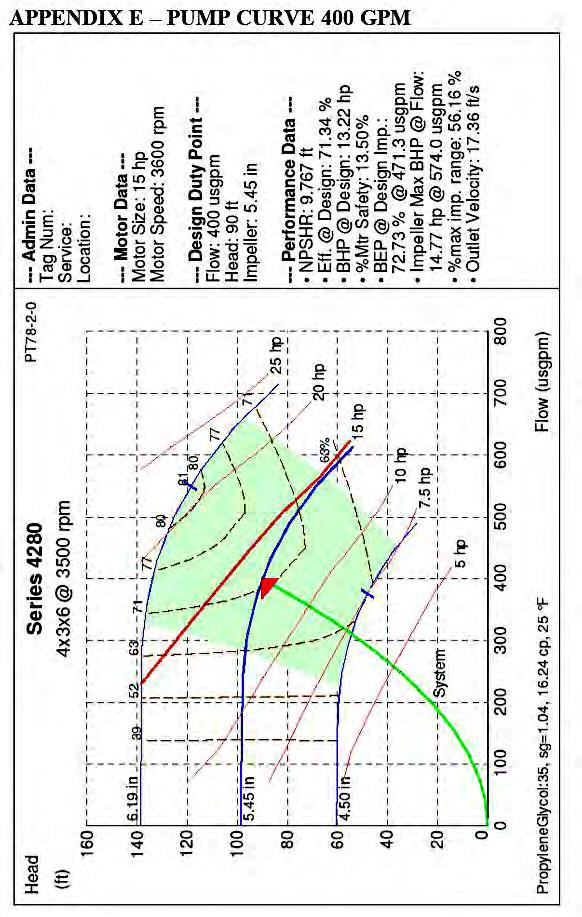
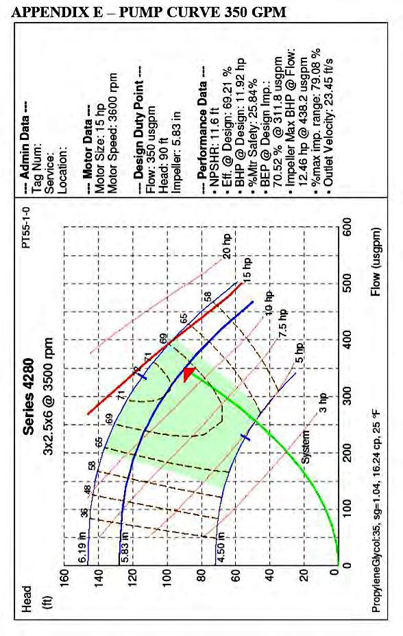
1 Glycol Pump Station Medium Temperature Secondary Glycol Refrigeration Systems Electrical Control Panel Fill Tank Air Separator Glycol Pumps Drain Pan Installation & Operation Manual SCAN CODE TO SEE LATEST MANUAL ONLINE P/N 1H _E August 2018 MANUAL- I/O PUMP STATION 1
 150, 200, 250, 300, 350, 400, 450 GLYCOL SECONDARY SYSTEM PREFIX N=Pump Station M=Previous Vintage Pump Station Frame Dimensions and Weights TABLE 1-0a: SYSTEM FRAME SIZES AND WEIGHT August 31,")

2 Model Reference and Flow Rates The Pump Station model numbers, for reference: N GS 450 K (may be followed by additional characters) PUMP VOLTAGE M=460/3/60 K= /3/60 P=575/3/60 GLYCOL FLOW RATE (GPM) 150, 200, 250, 300, 350, 400, 450 GLYCOL SECONDARY SYSTEM PREFIX N=Pump Station M=Previous Vintage Pump Station Frame Dimensions and Weights TABLE 1-0a: SYSTEM FRAME SIZES AND WEIGHT August 31, 2018 This warning does not mean that Hussmann products will cause cancer or reproductive harm, or is in violation of any product-safety standards or requirements. As clarified by the California State government, Proposition 65 can be considered more of a right to know law than a pure product safety law. When used as designed, Hussmann believes that our products are not harmful. We provide the Proposition 65 warning to stay in compliance with California State law. It is your responsibility to provide accurate Proposition 65 warning labels to your customers when necessary. For more information on Proposition 65, please visit the California State government website. 2
3 GLOSSARY Refrigerant: A fluid used to freeze or chill (as food) for preservation. Primary Refrigerant: A fluid such as R404A used in a vapor compression system to cool a secondary coolant. Secondary Coolant (Refrigerant): A fluid such as Propylene Glycol used to remove heat from cases and unit coolers and transfer the heat to the primary refrigerant through a heat exchanger. Secondary coolants used with these systems are for medium temperature applications only, meaning the working temperature should be above 0 F. A typical secondary coolant supply temperature is 20 F. Freezing Point: the temperature at which a solution begins to crystallize. Refractometer: Device for measuring the freezing point of the secondary fluid. Triple Duty Valve: This works as a throttling valve for the secondary fluid flow rate, a check valve when the pump to which it is attached is not running and a positive shut off valve mounted to the pump discharge. Pump: Device that circulates the secondary fluid throughout the system. Fill Tank: Tank used for storage of secondary fluid. This tank catches overflow from the pressure relief valve and automatic air vent. Secondary fluid can be added to the system using this tank after the initial filling process has taken place. Drain Valve: Valve to which a hose can be connected to add fluid to or remove fluid from the system. Balancing Valve: Valve used to measure and regulate the secondary coolant flow rate through a particular section of the secondary system. Balancing valves should be multi-turn, y-pattern, globe style valves with a positive shut off. Air Separator: Device used to remove air from the secondary coolant. Automatic Air Vent: Float-operated vent that allows air to escape to the atmosphere with a minimal loss of secondary fluid. Warm Fluid Defrost: A defrost method used in lieu of an off cycle or electric defrost where near room temperature secondary fluid is circulated through the cases/unit coolers to remove ice from the evaporator coils. 3
4 SECTION 1: INSTALLATION General Guidelines This manual is written as a basic guideline for the installation and operation of pump stations for both medium temperature secondary systems as well as for warm fluid systems to reject heat from water-cooled condensers. The primary refrigerant (ex. R404A) can vary depending on the customer s requirements. For detailed information regarding a specific component or application, contact your Hussmann representative. Pump Stations may be installed without the use of vibration pads. The pump station may also be anchored due to seismic concerns or if specified by the building engineer. Additional documentation for the installation is to be provided by the customer. All components must be installed according to manufacturer s specifications. All materials used must be compatible with the secondary coolant. Installation must comply with ANSI/ASME B31.5 Refrigeration Piping and Heat Transfer Components, ANSI/ASHRAE Standard 15 Safety Standard for Refrigeration Systems and local building codes. Inspect all components prior to installation to ensure that they are free from defects or foreign materials and to confirm that they comply with all pressure and temperature ratings. Shipping Damage All equipment should be thoroughly examined for shipping damage before and while unloading. This equipment has been carefully inspected at our factory, and the carrier has assumed responsibility for safe arrival. If damaged, either apparent or concealed, the claim must be made to the carrier. Apparent Loss or Damage If there is an obvious loss or damage, it must be noted on the freight bill or express receipt and signed by the carrier s agent; otherwise, carrier may refuse claim. The carrier will supply the necessary claim forms. Concealed Loss or Damage When loss or damage is not apparent until after equipment is uncrated, a claim for concealed damage is made. Upon discovering damage, make request in writing to carrier for inspection within 15 days and retain all packing. The carrier will supply inspection report and required claim forms. Pre-Installation System Cleaning Use a 1-2% solution of trisodium phosphate (TSP), or equivalent cleaner and distilled water to remove grease, mill scale, or other residues from construction. Repeat this process if necessary until the drained solution is clear and free from visible debris. The system should then be drained and flushed again using distilled water. Hussmann recommends distilled water for system flushing with 2% TSP. Dry nitrogen can be used for the initial pressure test (60 to 75 psi) hold for three hours. City water may be used for system cleaning if the water meets the requirements in the table at right. Water Quality Requirements Impurity Level Chlorides 25 ppm, max Sulfates 25 ppm, max Total Hardness, 80ppm as CaCO 3 Water above these levels should not be introduced in the system. Do not let city water sit in the system. The flushing process should be no more than 6 to 8 hours. 4
5 SECTION 2: PIPING GUIDELINES Piping Materials Any piping material that meets all pressure and temperature ratings, material compatibility requirements and state and local building codes may be used for medium temperature applications. Connections to the rack and pump station are copper as a standard. If the other materials are used, adapters would need to be ordered separately. 1. Plastic a. ABS is recommended over other types for this application because of the operating temperature. b. ABS plastic pipe should be solvent welded (glued) together as described on the glue can. c. Pipe fittings must be clean and dry. Cut pipe with a guillotine type cutter to get a clean, square cut; remove any burrs. Use purple primer on both pipe and fitting before gluing. Apply glue to both pipe and fitting and join with a twisting motion. Hold joint together for approximately 30 seconds to allow glue to set. Allow the joint to dry for 24 hours before putting into service. 2. Copper a. M, K, or L may be used. b. Copper-to-copper joints may be soft soldered or brazed so long as the braze/solder material contains no zinc or zinc chloride. Soft solder must be used where the component manufacturer s installation instructions recommend. c. Soft solder flux materials must contain no zinc and must also be water soluble. 3. Steel a. Schedule 40 carbon steel pipe or stainless steel pipe (or tubing) are acceptable. b. Must protect exterior from corrosion. c. Additional system cleaning is required. d. GALVANIZED STEEL IS NOT TO BE USED IN ANY SYSTEM CONTAINING INHIBITED PROPYLENE GLYCOL. Insulation Insulation should be used in secondary system piping to reduce the heat transfer to ambient air. In order to minimize the required insulation thickness, install pipe in air-conditioned space as much as possible. Do not size insulation for condensation prevention only. Pipe should be insulated according to local codes and customer specifications. When installing piping that has not been pre-insulated, there are several options for insulation. Closed-cell elastomeric insulation is very popular in refrigeration applications. This type of insulation can also be used in secondary system applications. For detailed information regarding this type of insulation, visit the Armaflex website at Other types of insulation that can be used are TRYMER and Styrofoam insulation. These are both made by Dow and are well suited for insulating pipe. Always follow the manufacturer s recommendations for insulation thickness and proper installation. 5
6 Pipe Connections Connecting Plastic With Metal Pipe DO NOT THREAD PLASTIC PIPE. A compression type fitting should be used. For larger pipe sizes, a flanged connection may be used. Air Vent Valves Manual air vent valves are recommended. Air vent valves should be located at piping high points where air will tend to collect. Momentarily open these vents to release trapped air a few times during startup. Provision should also be made for manual venting during the glycol loop fill. Vent valves should have a threaded connection to facilitate connection to a pipe or hose. It is important that the automatic vents be located in accessible locations for maintenance purposes, and that they be located where they can be prevented from freezing. Vents will vary with materials and local codes. The lowest points of the piping system must be purged of air, too, which typically involves heat exchanger coils. DRAIN VALVES Manual drain valves should be located at low points in the system or so that circuits can be drained of most of the fluid. This is used during maintenance or when changes to the system are made. ISOLATION VALVES Isolation valves should be used at a minimum on every circuit and as a standard on every coil. This will allow access to each circuit without shutting down the entire system. Ball valves should be used on all line sizes of 2 and less. Butterfly valves should be used on all sizes over 2. FILL CONNECTIONS Use the fill tank on the pump station to add any minor amounts of fluid. Do not connect to city water. Copper Pipe Schrader valve air vent brazed into copper turn down. (See Figure P1.) Plastic Pipe After the joint is assembled, drill and tap for a threaded 1/2-ID ABS pipe to socket fitting. Use ABS cement on the threads and do not over-tighten. Install a plastic ball valve on the fitting. (See Figure P2). To provide an air trap and assure that pipe cuttings do not get into the closed loop, install the 1/2-inchthreaded-to-ABS fitting in a TEE plug. Use a TEE at the turndown instead of an elbow. Install the plug and ball valve assembly after the joint is complete. (See Figure P3.) All When a turndown is not going to be accessible, a remote ball valve may be used. (See Figure P4.) Figure P1 Figure P2 Figure P3 Figure P4 6
7 Pipe Supports Suggested spacing for pipe supports is shown below. Verify state and local building codes for required support. Piping should be supported in a manner that minimizes heat transfer to the supports. Nominal Pipe Size (in) Distance between supports (ft) Schedule F Distance between supports (ft) Schedule F Pipe Support Spacing, ABS-DWV, Ft. Nominal Size 70 F 100 F 140 F 1-1/4 4-1/2 4-1/ / / / / /4 6-1/4 5-3/ /4 6-3/ /2 Water Loop Piping The variations of effective water piping design and layout are numerous and a comprehensive discussion is beyond the scope of this document. The local suppliers of pumps, pipe, valves, cooling towers, chemicals and controls are familiar with what works best in your area. Following are two basic design concepts applicable to water loop piping installations: Direct Return Piping Reverse Return Piping Direct Return Piping Direct return piping utilizes supply trunk lines. These supply lines decrease in size as branches reduce the water flow requirements through the trunk. The return trunk lines increase in size as branches join the trunk. Advantages Initial cost of the pipe may be less than the reverse return system. Disadvantages System balancing may be difficult since it must account for piping length, reductions in pipe size, and flow requirements. 7
8 Reverse Return Piping Reverse return piping uses equal sized supply and return lines throughout the installation. Because of the pipe layout, the head loss due to piping is nearly identical at any point along the glycol loop. Advantages This design reduces or eliminates the need for reduction fittings and allows use of larger quantities of one size pipe. Little balancing of glycol flow is required. A reverse return piping system will be essentially self-balancing. With proper prior planning, additional units may be added along the loop without the need to change pipe sizes. Disadvantages Initial cost of the pipe may be more than the direct return system. Expansion Loops Allowances for expansion and contraction in long straight runs of piping must be provided by expansion loops. Consult ASME B31.5 Refrigeration Piping Standard for specific design requirements. Use horizontal expansion loops to eliminate air traps. If vertical expansion loops are required, appropriate vent and drain valves must be installed. Valves 1. Mount solenoid and check valves inside cases if space permits. Solenoid, check and ball valves are to be installed upstream of the case/unit cooler heat exchangers. 2. Balancing valves are to be installed downstream of the case/unit cooler heat exchangers. Always follow the manufacturer s recommendations for installation. This includes orientation, braze vs. solder, flow direction, etc. Balancing valves should be multi-turn, y-pattern, globe style valves with a positive shut off. Adjust valves per manufacturer s recommendations. NOTE: All valves are available from Hussmann. Closed Loop Air Separator Air separators are standard on all units. An automatic air vent is included and piped directly out of the top of the air separator. In a circulating system, air tends to pocket where pipes turn in a downward direction. As a result, a vent is needed at high points when filling the closed system loop and at turn downs during start up. See section Air Vent Valves above. 8
9 SECTION 3: FIELD ELECTRICAL CONNECTIONS Incoming Supply and Control Power The control panel on this equipment includes disconnect switch and the standard configuration includes a control circuit transformer with no separate 120v control power is required. Field wiring must comply with the latest version of the NEC and state and local electrical codes. Equipment Control Wiring A chiller controller is integral with the secondary system controls. Individual analog and digital inputs from the secondary system peripheral devices are required to be field wired to the controller board inputs of the parallel compressor rack system controller. NOTE: The Chiller Controller and Chiller are included with the Primary Rack System. The standard control for the pump station uses a standalone controller. This controller has separate user documentation. This will take a dry run-enable contact. Provide a fault dry contact to the rack controller to monitor the operation of the pump station. Basics of Operation When the secondary system control circuit is powered up (either 120 or 208 volts) the chiller controller is powered. This must be programmed before starting the refrigeration system. Turn on the main on/off switch to energize the pump. There is a time delay to allow the pump to start and produce enough flow so that the system monitoring differential pressure does not produce an alarm at start-up. The pump will now run continuously until the specified changeover time, when Pump 1 will turn off and Pump 2 will turn on automatically (when in Auto Mode). There is a slight delay at the time of this changeover to prevent slamming of the discharge check valves. The glycol supply temperature is controlled with the rack suction pressure. The rack stages compressors on and off based on suction pressure input. The glycol freeze thermostat temperature and electronic expansion valve superheat settings are programmable by the user. Warm Fluid Defrost is an optional feature specified by the customer in place of off cycle or electric defrost (usually the latter). The temperature for the warm fluid is controlled by a three way mixing valve and temperature input in the defrost supply pipe. This temperature is controlled between 65 F and 75 F. Refer to Johnson Controls A350P for instructions on setting the temperature controller. A glycol solenoid receives a signal to open from the rack controller A/O board, allowing coolant to flow through the heat exchanger. A refrigerant solenoid also receives a signal to open, allowing refrigerant discharge gas to flow through the heat exchanger. A differential regulator is installed in the refrigerant discharge line past the oil separator to make sure some of the discharge gas goes through the heat exchanger. System Faults Pump Alarm: The system will monitor the secondary coolant flow. If the flow falls below the setpoint (set at the factory), the pump switching function is bypassed and the controls automatically switch from the currently active pump to the backup (when in Auto Mode). If the backup pump is also not operating properly, the system will cause the primary refrigerant solenoid to close and pump the rack down. The alarm must be reset manually at the control panel after the defective pump is serviced. 9
10 SECTION 4: FIELD PRESSURE TESTING Open all ball valves, balance valves and solenoid valve 1. Close all drains and vents. 2. Isolate the expansion tank and pumps. If there are any other components within the system that are not rated for the test pressure, isolate them as well. 3. Charge the system with dry nitrogen to 60 psig for 3 hours 4. Any leaks must be corrected. Once all leaks are stopped, system cleaning can begin. Variable Speed Drive Programming The VSD(s) will come factory programmed for voltage and amperage, but the pressure differential setpoint must be field set. Record the pressure differential reading with all solenoid valves open, fluid at temperature, and flow at 100%. This is the pressure set-point for the VSD to maintain. As solenoid valves close, the pump speed will be reduced to maintain the same pressure. Troubleshooting for Chilled Fluid Systems: Verify the following if it is not able to maintain the fluid temperature: Chiller approach between 5F and 8F Compressors fully loaded (none operating unloaded) Chiller Expansion Valve superheat, not hunting and fed with solid liquid refrigerant Fluid solution concentration correct Chiller pressure drop less than 7 psi on fluid side Troubleshooting for Case Temperature Issues: Verify the following if fluid temperature is met but case temperatures are not maintained: Check for high loads, heavy shopping or high store temperature and humidity. Check for correct balance valve setting or increase setting to allow higher flow. Check for air trapped in coils (purge either by venting or increasing the flow temporarily through the coil). Check for poor air flow through the coil. 10
, or cleaner and water to remove grease, mill scale, or other residues from construction.")

11 SECTION 5: PIPE SYSTEM CLEANING With the secondary system piping installed and pressure tested with air, the piping system must be flushed properly. Dow recommends that the new piping system should be cleaned using a 1-2% solution of trisodium phosphate (TSP), or cleaner and water to remove grease, mill scale, or other residues from construction. Repeat this process if necessary until the solution that is drained is clear and free from visible debris. The system should then be drained and flushed again using distilled water. System volume can be calculated during this stage by metering in the initial fill of the system or by chemical analysis of cleaning chemicals after known quantities are introduced into the system. 1. Verify that the pressure in the expansion tank is at the factory setting of 12 psig, then open all valves, excluding drain valves. 2. Close the butterfly valves at the bypass valve. 3. Connect a hose to the supply header to fill the system with water. 4. Connect a hose to the drain valve closest to the pump suction. 5. Fill the system and then with the fill water still running, allow the water to drain until the drain water becomes clear. 6. Close the drain valve and open the bypass butterfly valves. 7. Pressurize the system to approximately 30 psig (or 15 psig at highest system point.) 8. Vent the main loop lines. 9. Vent all system purge points from lowest to highest. 10. Turn off water. 11. Check to make sure the pumps are full of water. 12. Check the rotation of each pump by bumping the contactors, one at a time. 13. Start each pump and check the amperage. This amperage should be checked again once the triple duty valve has been adjusted. The final amperage may be lower than the initial reading. 14. Start one pump and allow it to run. Add water if necessary to maintain 20 psig return pressure. 15. Flush each case lineup by closing the solenoid on all other circuits for 1 minute. 16. Open all circuits and allow the system to run for at least 2 hours. Pre-Installation System Cleaning Use a 1-2% solution of trisodium phosphate (TSP), or equivalent cleaner and distilled water to remove grease, mill scale, or other residues from construction. Repeat this process if necessary until the drained solution is clear and free from visible debris. The system should then be drained and flushed again using distilled water. Hussmann recommends distilled water for system flushing with 2% TSP. Dry nitrogen can be used for the initial pressure test (60 to 75 psi) hold for three hours. City water may be used for system cleaning if the water meets the requirements as outlined in the table at right. Water Quality Requirements Impurity Level Chlorides 25 ppm, max Sulfates 25 ppm, max Total Hardness, 80ppm as CaCO 3 Water above these levels should not be introduced in the system. Do not let city water sit in the system. The flushing process should be no more than 6 to 8 hours. 11


.")
12 SECTION 6: START-UP AND OPERATION Drain the System 1. Turn off pumps. 2. Open all drain valves in the system. Purge remaining water with dry nitrogen. 3. If drain water is not clean, flush the system again. 4. Remove the cover of the suction guides and remove the start-up strainer from each. Reinstall the run strainer before restarting. Suction Guide Start-up Strainer Fill the System 1. Open all valves excluding vents and drains. 2. Check the freezing point of each container of secondary fluid with a refractometer. For 35% glycol, the freezing point should be 2 F. 3. Pump the pre-mixed fluid into the system. 4. Use the same air purge process as previously described. 5. Place any purged secondary fluid in the fill tank. 6. Make sure all air has been removed from the pumps. 7. Open the triple duty valves. 8. Restart one of the pumps. 9. Maintain 20 psig return pressure by adding secondary fluid as necessary. When using the fill tank, fill the tank up to the overflow (but not above). Open the ball valve between the tank and the pump suction. Allow the pump to pull the fluid into the system, making sure not to allow in any air. Close the valve when the pump no longer pulls in fluid or the fluid level nears the bottom of the tank. If 20 psig is not attained, add more fluid. 10. Fill each case line-up completely by closing the solenoid on all other circuits for 1 minute. 11. Check the freezing point of the system using a refractometer after the fluid has been circulated. 12. Allow the system to circulate for 1 hour. 12
13 System Fluids Never mix fluids from different manufacturers. Do not use concentrated fluid. Use only premixed (prediluted) fluid. A small amount of concentrate should be kept on hand to allow for adjustment to the solution during startup. A refractometer, calibrated for fluids at room temperature, is used to measure dilution. Hussmann recommends using distilled water. Do not use city water. Inhibited propylene glycol used in the system must be approved for use by the FDA. Hussmann recommends using Intercool P-323AA inhibited propylene glycol, specifically formulated for aluminum tubing. Only use pre-diluted solutions (35% inhibited propylene glycol). Dowfrost may be used, but ph must be maintained and / or adjusted. Interstate Chemical Company Inc Freedland Rd. Hermitage, PA (800) Requirements for system fluid: Pre-mixed 35% inhibited propylene glycol ph of solution 7.0 to 8.0. DO NOT INSTALL AUTOMATIC MAKEUP. Set Balance Valves (Field Installed) 1. Once the system has been filled, turn on the primary refrigeration. Coolant may need to be added, since the fluid will contract. 2. Set each balance valve at the flow rate on the store legend. 3. Use the manufacturer s recommendations for setting the valves. Set End of Loop Balance Valve (Field Installed, typically only on cold fluid systems) After setting the triple duty valve and balance valves throughout the system, find the pressure at the supply header while all case line-ups and cooling units are in cooling mode. This will be the normal system pressure. Set the end of loop balance valve for 20gpm while all case line-ups and cooling units are in cooling mode. Pump Maintenance IMPORTANT: Follow the lubrication procedures recommended by the pump and pump motor manufacturer. Check the lubrication instructions supplied with the pump and motor for the particular frame size indicated on the motor nameplate. 13
14 (GLYCOL SYSTEM PIPING GUIDELINES) PROPYLENE GLYCOL PROPERTIES Propylene glycol (PG): Very high viscosity at low temperatures; less toxic than ethylene glycol; risk of environmental pollution; most commercial products for indirect heat pump and refrigeration systems have good corrosion protection. PG is a colorless, odorless liquid that is generally recognized as safe by the U.S. Food and Drug Administration (FDA) in 21 CFR , for use as a direct food additive under the conditions prescribed. PG is used in cosmetics and in pharmaceuticals. PG has a wide range of practical applications such as antifreezes, coolants and aircraft deicing fluids; heat transfer and hydraulic fluids; solvents; food; flavors and fragrances; personal care products; plasticizers; and thermoset plastic formulations. PG is not acutely toxic (single dose, high exposure). It is essentially non-irritating to the skin and mildly irritating to the eyes. Numerous studies support that PG is not a skin sensitizer or a carcinogen. Typical freezing, boiling and burst points of propylene glycol solutions %PG Freezing Point Boiling Point Burst F C F C F
15 Density (lb./cu.ft) % Propylene Glycol Temp F Specific Heat (BTU/lb. F) % Propylene Glycol Temp F Thermal Conductivity (BTU/(hr*ft 2 )( F/ft) % Propylene Glycol Temp F Viscosity (cps) % Propylene Glycol Temp F It is recommended that a minimum of 30% by volume of fully inhibited, industrial grade propylene glycol with water be used on the condensing side, while 35% by volume propylene glycol be used on the evaporator side. NOTE: Do not mix like or unlike fluids from different manufacturers. Do not use automotive grade glycols 15
16 System Fluids Never mix fluids from different manufacturers. Do not use concentrated fluid. Use only premixed (pre-diluted) fluid. A small amount of concentrate should be kept on hand to allow for adjustment to the solution during startup. A refractometer, calibrated for fluids at room temperature, is used to measure dilution. Hussmann recommends using distilled water. Do not use city water. Inhibited propylene glycol used in the system must be approved for use by the FDA. Hussmann recommends using Intercool P-323AA inhibited propylene glycol, specifically formulated for aluminum tubing. Only use pre-diluted solutions (35% inhibited propylene glycol). Dowfrost may be used, but ph must be maintained and / or adjusted. Interstate Chemical Company Inc Freedland Rd. Hermitage, PA (800) Requirements for system fluid: Pre-mixed 35% inhibited propylene glycol ph of solution 7.0 to 8.0. DO NOT INSTALL AUTOMATIC MAKEUP. Set Balance Valves (Field Installed) For cold fluid systems, additional fluid may need to be added after the chillers bring down the temperature. Maintain approximately 15 psig at the highest point in the system. Record the pressure and temperature at the pump station (in the store log book). Case balance valves may be set at the flow rate shown on the store legend. Use the balance valve setting charts to estimate the flow rate for each valve (measuring pressure across each valve). After setting all valves and running the chilled fluid at final temperature, verify that solenoid valves are not cycling too much or too little on any circuit. It is recommended to verify the circuit cycling again after the store has been opened since flow rates are estimated based on standard conditions. Record the actual valve settings of each circuit balance valve and record. Set End of Loop Balance Valves (Field Installed, typically only on cold fluid systems) After setting the triple duty valve and balance valves throughout the system, find the pressure at the supply header while all case line-ups and cooling units are in cooling mode. This will be the normal system pressure. Set the end of loop balance valve for 20gpm while all case lineups and cooling units are in cooling mode. Pump Maintenance IMPORTANT: Follow the lubrication procedures recommended by the pump and pump motor manufacturer. Check the lubrication instructions supplied with the pump and motor for the particular frame sixe indicated on the motor name plate 16

17 Balancing Valve Secondary Fluid Ship Loose Curve 1: Armstrong Balancing Valve - Flow Rates and Pressure Drop 17

18 18

19 19
20 20
21 Typical Pump Station Dimensions ELECTRICAL CONTROL PANEL FILL TANK REAR ACCESS REQUIRED FOR STRAINER REMOVAL DISCHARGE CONNECTION SINGLE VSD, STANDARD BACK-UP VSD, OPTIONAL DRAIN PAN SUCTION CONNECTION SUCTION CONNECTION PUMP STATION GUIDE WITH START-UP STRAINER (MUST BE ACCESSIBLE) EXPANSION TANK
22 22
23 23
24 24
25 25

26 26

27 27

28 28

29 29
30 To obtain warranty information or other support, contact your Hussmann representative. Please include the model and serial number of the product. Hussmann Corporation, Corporate Headquarters: Bridgeton, Missouri, U.S.A October 2012
Condensing Unit Installation and Operating Instructions
 Bulletin WCU_O&I 01 June 2003 Condensing Unit Installation and Operating Instructions WCU Air Cooled Condensing Unit Table of Contents Section 1. Section 2. Section 3. Section 4. Section 5. Section 6.
CS/CD/CP AIR COOLED CONDENSING UNITS (P/N E207120C R2)
") CS*/CD*/CP* Series Air Cooled Condensing Units Operating and Installation Manual CS/CD/CP AIR COOLED CONDENSING UNITS (P/N E207120C R2) TABLE OF CONTENTS I. Receipt of Equipment 2 II. Piping...4 III. System
CS*/CD*/CP* Series Air Cooled Condensing Units Operating and Installation Manual CS/CD/CP AIR COOLED CONDENSING UNITS (P/N E207120C R2) TABLE OF CONTENTS I. Receipt of Equipment 2 II. Piping...4 III. System
PARALLEL RACK SYSTEM INSTALLATION & OPERATIONS MANUAL With Master Rack Compressor Sequencer
 PARALLEL RACK SYSTEM INSTALLATION & OPERATIONS MANUAL With Master Rack Compressor Sequencer 5/16 Rev. A 57-02509 2 Contents INTRODUCTION... 4 WARNING LABELS AND SAFETY INSTRUCTIONS... 5 PS SERIES PARALLEL
Condensing Unit Installation and Operating Instructions
 Bulletin ACU_O&I 02 August 2016 Condensing Unit Installation and Operating Instructions ACU Air Cooled Condensers Table of Contents Section 1. General Information... 2 Section 2. Refrigeration Piping...
CHILLER. Operator s & Installation Manual
 CHILLER MODELS: CH1001-A Operator s & Installation Manual Release Date: August 9, 2002 Publication Number: 620914301 Revision Date: May 6, 2010 Revision: E Visit the IMI Cornelius web site at www.cornelius.com
Installation, Operation and Maintenance Manual
 Installation, Operation and Maintenance Manual Packaged Chiller Models CC 6601, 6501, 6401, 6301, 6201, 6101 For Service, please contact Pfannenberg Service Company: U.S.A. Pfannenberg Inc. 68 Ward Road.
B. Unit construction shall comply with ASHRAE 15 Safety Code, NEC, and ASME applicable codes (U.S.A. codes).
.") Guide Specifications PART 1 GENERAL 1.01 SYSTEM DESCRIPTION Microprocessor controlled, air-cooled liquid chiller utilizing scroll compressors, low sound fans, hydronic pump system and optional fluid storage
Guide Specifications PART 1 GENERAL 1.01 SYSTEM DESCRIPTION Microprocessor controlled, air-cooled liquid chiller utilizing scroll compressors, low sound fans, hydronic pump system and optional fluid storage
Daikin Water Cooling, Heating, and High Capacity Booster Coils
 Installation and Maintenance Manual IM 900 Daikin Water Cooling, Heating, and High Capacity Booster Coils Group: Applied Air Part Number: IM 900 Date: February 2008 Types HI-F5, E-F5 2008 Daikin International
1025, BOUL. MARCEL-LAURIN INSTRUCTION MANUAL FOR WATER COOLED ENVIROCHILL CHILLER. Prepared par Claude Gadoury, P. Eng MTL TECHNOLOGIES INC.
 WYETH-AYERST CANADA INC. 1025, BOUL. MARCEL-LAURIN S T - L A U R E N T, Q U É B E C INSTRUCTION MANUAL FOR WATER COOLED ENVIROCHILL CHILLER MODEL P448800LT--55WC--22C66S Prepared par Claude Gadoury, P.
VS SERIES NH3 STEAM VAPORIZERS OPERATION MANUAL
 VS SERIES NH3 STEAM VAPORIZERS Revised March 1997 OPERATION MANUAL CONTENTS PAGE 1. GENERAL................................... 1 Figure 1-1 - VS Series Vaporizer......................... B How to Select
Chiller installation, contractor s scope of work:
 Chiller installation, contractor s scope of work: See complete DTS O&M Manual for further details Pre-planning: Provide installation surface Either, ground level concrete pad 5 W x 12 L x min 4 depth,
Air Cooled Condenser Installation and Operating Instructions
 Bulletin CAC_O&I 02 August 2016 Air Cooled Condenser Installation and Operating Instructions CAC Air Cooled Condensers Table of Contents Section 1. General Information... 2 Section 2. Refrigeration Piping...
CROWN. Boiler Co. Santa-Fe Series. Hydronic Air Handlers INSTALLATION, OPERATION & MAINTENANCE INSTRUCTIONS
 CROWN Boiler Co Santa-Fe Series Hydronic Air Handlers INSTALLATION, OPERATION & MAINTENANCE INSTRUCTIONS These instructions must be affixed on or adjacent to the air handler Models: SAC049A20 SAC059A25
PACKAGED AIR COOLED Product Data Catalog
 PACKAGED AIR COOLED Product Data Catalog MODELS ASP-10A ASP-15A ASP-20A ASP-00P ASP-00F ASP-00G A MEMBER OF MARDUK HOLDING COMPANY, LLC The Leader in Modular Chillers ETL and CSA Approved CHILLER MODULES
Liebert CSU3000 Chiller
 CSI 15620 - Packaged Water Chillers Liebert CSU3000 Chiller Guide Specifications for 7.5-37 Ton CS/CD/CT Models 1.0 GENERAL 1.1 CS/CD MODELS The main-frame coolant supply unit shall be a Liebert Model,
PS SERIES PARALLEL RACK SYSTEM GLYCOL CHILLER START UP GUIDE 11/03/2015 Rev 00
 PS SERIES PARALLEL RACK SYSTEM GLYCOL CHILLER START UP GUIDE 11/03/2015 Rev 00 1 Contents INTRODUCTION... 3 WARNING LABELS AND SAFETY INSTRUCTIONS... 4 PARALLEL RACK NOMENCLATURE... 5 GENERAL RACK DESCRIPTION...
Multiaqua Chiller Manual
 Rev. 1.1 Multiaqua Chiller Manual The Multiaqua Chiller System is the only air conditioning/refrigeration system of its kind in the world today offering the degree of application flexibility described
NON-CYCLING REFRIGERATED AIR/GAS DRYERS QPNC 75 to QPNC 250 OPERATOR S MANUAL
 NON-CYCLING REFRIGERATED AIR/GAS DRYERS QPNC 75 to QPNC 250 OPERATOR S MANUAL DATE OF PURCHASE: MODEL: SERIAL NO.: Record above information from nameplate. Retain this information for future reference.
MODEL YVAA EQUIPMENT PRE-STARTUP AND STARTUP CHECKLIST CUSTOMER: LOCATION: ADDRESS: CUSTOMER ORDER NO: PHONE: JCI CONTRACT NO: JOB NAME:
 Supersedes: 201.28-CL2 (817) Form 201.28-CL2 (1017) MODEL YVAA EQUIPMENT PRE-STARTUP AND STARTUP CHECKLIST CUSTOMER: LOCATION: ADDRESS: PHONE: JOB NAME: CUSTOMER ORDER NO: JCI CONTRACT NO: CHILLER MODEL
PDF Created with deskpdf PDF Writer - Trial ::
 Instruction Manual Index Introduction Uncrating and Checking for Damage Locating Your Unit Installation Fill Tank Process Connections Pre Startup Startup Sequence Trouble Shooting Chart Operating Lights
MACH N-407 Heat Pump Air-Cooled Chiller
 MACH060-01-N-407 Heat Pump Air-Cooled Chiller Heat Pump Air-Cooled Chillers for Global Residential and Light Commercial Microclimates MACH NOMENCLATURE BREAKDOWN MACH-060-01 - N - 407 Refrigerant Type
Table of Contents. Page 2 of 28
 Rev. 1.1 Table of Contents Page Introduction 3 System Description 4 Electrical & Physical Data 5-6 Description of Electrical Controls 7-8 Chiller Controls Sequence of Operation 9 System Faults 10 Refrigeration
SECTION ROTARY-SCREW WATER CHILLERS
 PART 1 GENERAL 1.01 SECTION INCLUDES A. Factory-assembled packaged chiller. B. Charge of refrigerant and oil. C. Controls and control connections. D. Chilled water connections. E. Electrical power connections.
Water-Cooled Dual Compressor Screw Chiller
 Installation Manual IM 692-1 Group: Chiller Part Number: 629955 Effective: May 1997 Supersedes: IM663-1 IM683 IM692 Water-Cooled Dual Compressor Screw Chiller Installation Manual PFS 155C through PFS 210C,
Thomas J Kelly. Fundamentals of Refrigeration. Sr. Engineering Instructor Carrier Corporation. August 20, Page number: 1.
 Thomas J Kelly Sr. Engineering Instructor Carrier Corporation August 20, 2003 1 SESSION OBJECTIVES At the conclusion of this session you should be able to: 1. Describe the basics principles of refrigeration
Installation & Operation Manual Models: TSU
 TSU-I-O Rev A Installation & Operation Manual Models: TSU 150-940 CAUTION: This appliance is not intended for potable water. This manual must only be used by a qualified heating installer / service technician.
DENVER PUBLIC SCHOOLS DESIGN AND CONSTRUCTION STANDARDS This Standard is for guidance only. SECTION WATER TREATMENT
 PART 0 DESIGN STANDARDS 0.01 GENERAL DESIGN GUIDELINES A. Open Cooling Towers: a treatment system utilizing chemicals and biocides that contain no heavy metals and are non-carconigenic to prevent corrosion,
SECTION HYDRONIC PIPING AND SPECIALTIES
 SECTION 15511 HYDRONIC PIPING AND SPECIALTIES PART 1 GENERAL 1.01 SUMMARY A. Section Includes: 1. Pipe Materials. 2. Fittings. 3. Specialty Items. 4. Glycol Antifreeze Protection. 5. Process Cooling B.
Parallel Rack Systems
 Parallel Rack Systems Installation & Service Manual IMPORTANT Keep in store for future reference! P/N 0427598_B July 2013 P/N 0427598_B iii TABLE OF CONTENTS INSTALLATION Shipping Damage....................
Evaporative Cooling products
 user manual Evaporative Cooling products OPERATION - MAINTENANCE Z0582995_A ISSUED 06/2017 READ AND UNDERSTAND THIS MANUAL PRIOR TO OPERATING OR SERVICING THIS PRODUCT general information Note Recold
Contour TM Screw Compressors
 Contour TM Screw Compressors Semi-Hermetic Compact Operating Instruction SCH1 High Temp Compressors Form No. 99-77 1. Introduction This series of semi-hermetic compact screw compressors is designed for
PS SERIES PARALLEL RACK SYSTEM GLYCOL CHILLER START UP GUIDE. Master Rack Compressor Sequencer 7/21/2017
 PS SERIES PARALLEL RACK SYSTEM GLYCOL CHILLER START UP GUIDE Master Rack Compressor Sequencer 7/21/2017 1 2 Contents INTRODUCTION... 4 WARNING LABELS AND SAFETY INSTRUCTIONS... 5 PARALLEL RACK NOMENCLATURE...
AQUA LOGIC S MULTI-TEMP Water-Cooled Marine Duty Series chiller
 AQUA LOGIC S MULTI-TEMP Water-Cooled Marine Duty Series chiller INSTALLATION & OPERATING INSTRUCTIONS Effective 8-19-15 Thank you for purchasing an Aqua logic chiller. It has been designed and built to
EQUIPMENT PRE-STARTUP AND STARTUP CHECKLIST TEL NO: ORDER NO: CONTRACT NO:
 Supersedes: (316) Form QTC4-CL2 (617) MODEL QTC4 EQUIPMENT PRE-STARTUP AND STARTUP CHECKLIST CUSTOMER: ADDRESS: PHONE: JOB NAME: LOCATION: CUSTOMER ORDER NO: TEL NO: ORDER NO: CONTRACT NO: CHILLER MODEL
SYSTEM DESIGN REQUIREMENTS
 P a g e 1 SYSTEM DESIGN REQUIREMENTS WFC-S SERIES WATER-FIRED SINGLE-EFFECT ABSORPTION CHILLERS / CHILLER-HEATERS Yazaki WFC-S Series water-fired chillers and chiller-heaters are available with nominal
Direct Drive Fluid Coolers
 H-IM-68 March 2000 Part No. 25001301 Replaces H-IM-44 Direct Drive Fluid Coolers Installation and Maintenance Data Table of Contents Inspection System Warranty Installation...2 Rigging Instructions...3
.2 Section Waste Management and Disposal.
 Issued 2005/06/01 Section 15624 Packaged Rotary Screw Water Chillers Page 1 of 5 PART 1 General 1.1 RELATED SECTIONS.1 Section 01330 Submittal Procedures..2 Section 01355 Waste Management and Disposal..3
4201 Lien Rd Madison, WI Owner s Manual Therma-Stor III Heat Recovery System. Installation, Operation & Service Instructions
 4201 Lien Rd Madison, WI 53704 TS-140F Revised 09-10 Owner s Manual Therma-Stor III Heat Recovery System Installation, Operation & Service Instructions Read and Save These Instructions Table Of Contents
COLMAC COIL. Installation, Operation, and Maintenance ENG Rev A. Air Cooled Fluid Coolers. Contents. When you want Quality, specify COLMAC!
 COIL Manufacturing Inc. When you want Quality, specify COLMAC! Installation, Operation, and Maintenance ENG00018621 Rev A Air Cooled Fluid Coolers Contents 1. SAFETY INSTRUCTIONS... 1 2. MODEL NOMECLATURE...
OPERATION & MAINTENANCE MANUAL RHS680
 OPERATION & MAINTENANCE MANUAL RHS680 Refrigerant Handling System 4075 East Market Street York, PA 17402 800-468-2321 tech@rtitech.com Manual P/N 035-80740-00 (Rev 1- May 22, 2001) TABLE OF CONTENTS Startup
INSTALLATION INSTRUCTIONS GEO PRIME TANK. (Patent Pending) GPC
 GPC") INSTALLATION INSTRUCTIONS GEO PRIME TANK (Patent Pending) GPC Table of Contents General Description 2 Installation 3 Flushing and Purging 5 Initial Start up 7 Adding or Checking Fluid 8 Replacing a Pump
INSTALLATION INSTRUCTIONS GEO PRIME TANK (Patent Pending) GPC Table of Contents General Description 2 Installation 3 Flushing and Purging 5 Initial Start up 7 Adding or Checking Fluid 8 Replacing a Pump
RESEARCH AND TECHNOLOGY BUILDING RENOVATION 05/18/09 SECTION REFRIGERANT PIPING AND SPECIALITIES
 SECTION 23 23 00 REFRIGERANT PIPING AND SPECIALITIES PART 1 - GENERAL 1.1 SUMMARY A. Section Includes: 1. Refrigerant piping. 2. Unions, flanges, and couplings. 3. Pipe hangers and supports. 4. Refrigerant
YCIV Hz & Hz
 YCIV 0590-1500 50Hz & 0157-0397 60Hz Start-up Checklist SERVICE POLICY & PROCEDURES Supersedes: Nothing Form 201.23-CL1 (309) Commissioning PREPARATION Commissioning of this unit should only be carried
EarthLinked SW Series Compressor Unit R-410A Quik-Start Instructions
 EarthLinked SW Series Compressor Unit R-410A Quik-Start Instructions CONTENTS PAGE Pre-Installation 3 Placement & Mechanical Information 4 System Application Options 10 Antifreeze Protection 14 Electrical
Installation, Operating & Maintenance Instructions. High Performance Horizontal Models: HH & CH
 Installation, Operating & Maintenance Instructions High Performance Horizontal Models: HH & CH Table of Contents Table of Contents... 2 Product Safety... 2 Important Information About Safety Instructions...
Owner s Manual Therma-Stor II Heat Recovery System
 PO Box 8680 Madison, WI 53708 TS-138C Revised 8/08 Owner s Manual Therma-Stor II Heat Recovery System Installation, Operation & Service Instructions Read and Save These Instructions Table Of Contents 1.
Rev B, 9/2/2009. Kodiak Chiller Overview
 930-0001 Rev B, 9/2/2009 Kodiak Chiller Overview Presentation Outline Phone: 781-933-7300 Lytron Technical Support Contact Information 3 Introduction 4 Part I: Unpacking 5 Part II: Installation 7 Part
CH250 AND CH251 CHILLERS
 CH250 AND CH251 CHILLERS Operator s & Installation Manual Release Date: April 19, 2004 Publication Number: 620914801 Revision Date: May 15, 2015 Revision: G Visit the Cornelius web site at www.cornelius.com
Chiller Plant Design. Julian R. de Bullet President debullet Consulting
 Chiller Plant Design Julian R. de Bullet President debullet Consulting 703-483-0179 julian@debullet.com This ASHRAE Distinguished Lecturer is brought to you by the Society Chapter Technology Transfer ASHRAE
KR Series Air Defrost Unit Coolers Operating and Installation Manual
 KR Series Air Defrost Unit Coolers Operating and Installation Manual KR Air Defrost Unit Coolers (PN E108317_L) TABLE OF CONTENTS 1 RECEIPT OF EQUIPMENT... 2 1.1 INSPECTION... 2 1.2 LOSS OF GAS HOLDING
INSTALLATION INSTRUCTIONS TXV Horizontal Duct Coils EHD
 TXV Horizontal Duct s EHD These instructions must be read and understood completely before attempting installation. It is important that the Blower and Duct System be properly sized to allow the system
Operation and Maintenance Haskris LX-Series, R-Series, WW-Series, OPC-Series
 Section 1: Temperature Control Your Haskris will have one of three different types of controller. Use table 1-1 to identify the relevant controller. The controller may appear different than examples. Contact
RECORD SUBMITTAL COVER SHEET
 RECORD SUBMITTAL COVER SHEET PROJECT TITLE: AXCELLERATE PHARMA EQUIPMENT DESCRIPTION: CARRIER AQUASNAP AIR-COOLED CHILLER CH-1 OWNER: AXCELLERATE PHARMA MECHANICAL ENGINEER: ARDEN DATE: JUNE 27, 2014 SUBMITTED
CO2 TRANSCRITICAL BOOSTER SYSTEMS
 CO2 TRANSCRITICAL BOOSTER SYSTEMS William Katz Sr. Technical Writer Hillphoenix 2016 Gees Mill Road Conyers, GA 30013 Tel: 678-613-9364 Email: william.katz@hillphoenix.com Refrigeration systems for supermarkets
LABORATORY AIR COMPRESSORS AND VACUUM PUMPING SYSTEMS
 SECTION 22 20 00 LABORATORY AIR COMPRESSORS AND VACUUM PUMPING SYSTEMS PART 1 - GENERAL 1.1 RELATED DOCUMENTS: A. The Conditions of the Contract and applicable requirements of Division 1, "General Requirements",
EcoVision II Plus Door Upgrade for D6 Kysor Warren Multi-deck Merchandisers
 EcoVision II Plus Door Upgrade for D6 Kysor Warren Multi-deck Merchandisers IMPORTANT Keep in store for future reference! Installation & Operation Manual P/N 0537298_A July 2014 MANUAL- I/O ECOVISION II
Commercial Refrigeration
 Commercial Refrigeration A science of vague assumptions based upon debatable figures taken from inconclusive experiments performed with instruments of problematical accuracy by persons of doubtful reliability
PS SERIES PARALLEL RACK SYSTEM START UP GUIDE
 PS SERIES PARALLEL RACK SYSTEM START UP GUIDE 5/16 Rev. A 57-02508 1 Contents INTRODUCTION... 3 WARNING LABELS AND SAFETY INSTRUCTIONS... 4 PARALLEL RACK NOMENCLATURE... 5 GENERAL RACK DESCRIPTION... 6
INSTALLATION INSTRUCTIONS Cased N Coil, Horizontal ENH4X
 INSTALLATION INSTRUCTIONS Cased N Coil, Horizontal ENH4X NOTE: Read the entire instruction manual before starting the installation. TABLE OF CONTENTS PAGE SAFETY CONSIDERATIONS... 1 INTRODUCTION... 1 INSTALLATION...
INTRODUCTION. Special Applications of Package Air Conditioners. Instant Cooling Requirement in Wedding Ceremonies
 Pakistan s Largest Manufacturers of Air-Conditioners PACKAGE TYPE UNIT FOR MOBILE APPLICATIONS Provides Turnkey Projects Conceptual Planning to Commissioning of HVACR Projects THE LARGEST MANUFACTURER
Exclusively published and distributed by Architectural Computer Services, Inc. (ARCOM) for the AIA
 for the AIA") Page 236423-1 Copyright 2009 by The American Institute of Architects (AIA) Exclusively published and distributed by Architectural Computer Services, Inc. (ARCOM) for the AIA Modified by MSU Physical Plant
Page 236423-1 Copyright 2009 by The American Institute of Architects (AIA) Exclusively published and distributed by Architectural Computer Services, Inc. (ARCOM) for the AIA Modified by MSU Physical Plant
NOBURST. NOBURST Antifreeze & Heat Transfer Fluid Factory Pre-mixed Freeze Protection for Water-based Heating and Cooling Systems
 NOBURST NOBURST Antifreeze & Heat Transfer Fluid Factory Pre-mixed Freeze Protection for Water-based Heating and Cooling Systems NOBURST non-toxicq antifreeze solutions are to be used in place of water
HVAC BASIC MATERIAL AND METHODS 1.01 RELATED CORNELL DESIGN AND CONSTRUCTION STANDARDS
 230500 HVAC BASIC MATERIAL AND METHODS PART 1 GENERAL 1.01 RELATED CORNELL DESIGN AND CONSTRUCTION STANDARDS A. Section 230000 Basic HVAC Requirements B. Section 230523 Valves C. Section 230510 Chilled
WMHP Series R410a Heat Pump INSTALLATION INSTRUCTIONS
 WMHP Series R410a Heat Pump INSTALLATION INSTRUCTIONS **WARNING TO INSTALLER, SERVICE PERSONNEL AND OWNER** Altering the product or replacing parts with non authorized factory parts voids all warranty
INSTALLATION, OPERATING & MAINTENANCE INSTRUCTIONS FOR 350 SERIES CIRCULATION HEATERS
 INDEECO Circulation Heaters are designed to provide years of trouble free operation if properly installed and maintained. Please read and follow these instructions for installing and maintaining the heater.
XSTREAM Valve System With A.R.M.E.D. Technology Service & Installation Instructions Page 1
 Page 1 WHY should I install the XSTREAM Valve System? XDX is more efficient, saving on power consumption. Use of XDX system decreases defrost cycles. XDX maintains more consistent product temperatures,
MAC N-407 Air-Cooled Chiller
 MAC036-01-N-407 Air-Cooled Chiller Air-Cooled Chillers for Global Residential and Light Commercial MicroClimates MAC036 NOMENCLATURE BREAKDOWN MAC036-01 - N - 407 Refrigerant Type Air-Cooled Chiller 036=
Title: YALE OFFICE OF FACILITIES PROCEDURE MANUAL Chapter: 01 - Yale Design Standard Division: HVAC Standards
 Date Description of Change Pages / Sections Modified ID 6/15/16 Entire document - mgl44 PART 1 - INTRODUCTION 1.1 PURPOSE A. This section is intended to define the general installation and minimum product
AMERICAN EQUIPMENT SYSTEMS A Division Of Trevor-Martin Corporation th Terrace North Clearwater, Florida 33762
 AMERICAN EQUIPMENT SYSTEMS A Division Of Trevor-Martin Corporation 4151 112 th Terrace North Clearwater, Florida 33762 COMMERCIAL REFRIGERANT DESUPERHEATER WASTE HEAT RECOVERY INSTALLATION/OPERATION/MAINTENANCE
SPX SERIES PACKAGED AIR CONDITIONING/HEAT PUMP UNITS INSTALLATION, OPERATION AND MAINTENANCE INSTRUCTIONS
 SPX SERIES PACKAGED AIR CONDITIONING/HEAT PUMP UNITS INSTALLATION, OPERATION AND MAINTENANCE INSTRUCTIONS **WARNING TO INSTALLER, SERVICE PERSONNEL AND OWNER** Altering the product or replacing parts with
WILKERSON MODELS DE3, DE4 AND DE5 COMPACT HEATLESS AIR DRYERS
 INSTRUCTION MANUAL FOR WILKERSON MODELS DE3, DE4 AND DE5 COMPACT HEATLESS AIR DRYERS DE3 - DE5 OPERATIONS GENERAL This instruction manual covers the installation, operation, maintenance and troubleshooting
CHILLER. Model CH3000. Operator s & Installation Manual
 CHILLER Model CH3000 Operator s & Installation Manual Release Date: February 14, 2011 Publication Number: 620054173OPR Revision Date: May 08, 2014 Revision: B Visit the Cornelius web site at www.cornelius.com
Installation, Operating & Maintenance Instructions. Horizontal Models: LH & HL
 Installation, Operating & Maintenance Instructions Horizontal Models: LH & HL Table of Contents Table of Contents... 2 Product Safety... 2 Important Information About Safety Instructions... 2 Receiving...
RDT Refrigeration Book
 RDT Refrigeration Book Indoor / Outdoor Air-Cooled Systems Indoor Air-Cooled Systems 1. Shorter line runs. 2. Systems located off roof or dock space. 3. Weather covers are not required (saves cost). 4.
MAC Chiller Installation and Operation Manual
 MAC Chiller Installation and Operation Manual TABLE OF CONTENTS...PAGE Table of Contents...40 Multiaqua Chiller Manual Introduction...41 System Description & Sequence of Operation...42 Electrical & Physical
AIR COOLED FLUID COOLER MODELS FRAC-3/4 TO FRAC-3 FVAC-5 TO FVAC-216
 Russell MULTICON INSTALLATION AND MAINTENANCE MANUAL Bulletin No. 411.1 April, 1999 AIR COOLED FLUID COOLER MODELS FRAC-3/4 TO FRAC-3 FVAC-5 TO FVAC-216 US Russell 221 S. Berry St. Brea, CA 92821 Tel (714)
Water-Cooled Scroll Compressor Chillers
 Installation, and Maintenance Manual IMM WGZ-2 Group: Chiller Part Number: 331374401 Effective: October 2005 Supercedes: IOMM WGZ-1 Water-Cooled Scroll Compressor Chillers WGZ 030AW To WGZ 120AW, Packaged
OPERATION & MAINTENANCE MANUAL AC860
 OPERATION & MAINTENANCE MANUAL AC860 Refrigerant Handling System Manual P/N 035-80913-00 TABLE OF CONTENTS Startup & Safe Operation... 1 Introduction to the AC860... 2 Control Panel... 3 Keypad Functions...
Service Step by Step Trouble-Shooting Check-List
 WARNING: Only Data Aire trained technician or experience technicians should be working on Data Aire Equipment. Protect yourself at all times and work safe. Date: Dates at the job site: From: to Job#: Serial#:
Eclipse Technical Training CME686 CME810 CP686 CP886 CP1086
 Eclipse Technical Training CME686 CME810 CP686 CP886 CP1086 In This Presentation What Eclipse is Components and their functions Installation Operation Maintenance Service Diagnosis The Eclipse System The
A hydronic system controls comfort by delivering heated or cooled fluid to the conditioned space through pipes.
 Introduction to Hydronics A hydronic system controls comfort by delivering heated or cooled fluid to the conditioned space through pipes. Hydronic heating systems use hot water or steam to deliver the
SERIES NIM. Low Temperature Merchandisers PLEASE READ THIS MANUAL BEFORE USING THE PRODUCT
 SERIES NIM Low Temperature Merchandisers PLEASE READ THIS MANUAL BEFORE USING THE PRODUCT Hussmann Monterrey, Mexico Carretera Mexico-Laredo KM. 1009 Cienga de Flores, Nuevo Leon 65550 Mexico Phone: (52)
User s Information Manual
 User s Information Manual CONDENSING GAS BOILER 220/299/300/399 If the information in this manual is not followed exactly, a fire or explosion may result, causing property damage, personal injury or loss
Operation Manual SCT14B and SCT18B. Inspection. 3 General Description. 3 General Requirements. 3 Standard Features.
 Spot Cooling Systems, Inc. 120 Century Drive Suite 00 Carrollton, TX 7006 00-6-776 Operation Manual SCT1B and SCT1B Warning! Improper installation, adjustment, alteration, service, or maintenance can cause
Experienced Worker Assessment Blueprint HVAC - Heating, Ventilation and Air Conditioning
 Blueprint HVAC - Heating, Ventilation and Air Conditioning Test Code: 0144 / Version: 02 Specific Competencies and Skills Tested in this Assessment: Electricity Demonstrate understanding of basic AC/DC
SERIES NAV S Display Merchandisers
 SERIES NAV S Display Merchandisers Medium Temperature Merchandisers PLEASE READ THIS MANUAL BEFORE USING THE PRODUCT Installation & Operation Manual P/N 2400204D NAV S Series May 2006 HUSSMANN CORPORATION
Bulletin , March Electric Hot Gas Bypass Valves
 Bulletin 100-60, March 2018 Electric Hot Gas Bypass Valves PAGE 2 / Bulletin 100-60 10 FEATURES AND BENEFITS SDR-4 Direct temperature control Tight shutoff when closed Can be interfaced with direct digital
SECTION GENERAL-SERVICE COMPRESSED-AIR SYSTEMS
 PART 1 GENERAL 1.01 SECTION INCLUDES A. Pipe and Pipe Fittings. B. Air compressor. C. Air receiver and accessories. D. Aftercooler. E. Refrigerated air dryer. F. Pressure reducing station. 1.02 RELATED
EXTREME HC-2 Reverse Osmosis System
 EXTREME HC-2 Reverse Osmosis System Leader Evaporator Co., Inc. 49 Jonergin Drive Swanton, VT 05488 Tel: 802-868-5444 www.leaderevaporator.com Contents INTRODUCTION... 3 THEORY OF OPERATION... 4 Terms...
C. ASME Compliance: Fabricate and label water chiller heat exchangers to comply with ASME Boiler and Pressure Vessel Code: Section VIII, Division 1.
 SECTION 236426 - ROTARY-SCREW WATER CHILLERS PART 1 - GENERAL 1.1 SUMMARY A. This Section includes packaged, water cooled or air cooled as scheduled, electric-motor-driven, rotary-screw water chillers
Installation Instructions
 Installation Instructions Part No. 30RA-900---057 and 30RA-900---060 30RAP010-150 Remote Cooler Mounting Accessory SAFETY CONSIDERATIONS Installation of this accessory can be hazardous due to system pressures,
Installation, Operating & Maintenance Instructions. Air Handler Models: AH & AV
 Installation, Operating & Maintenance Instructions Air Handler Models: AH & AV Table of Contents Table of Contents... 2 Product Safety... 2 Important Information About Safety Instructions... 2 Receiving...
MODELS LIST. Nominal Capacity RT
 1. MODELS LIST. NOMENCLATURE 3. FEATURES 4. PRODUCT DATA 5. PERFORMANCE CORRECTION 6. ANTIFREEZE 7. INSTALLATION 8. ELECTRICAL DATA 9. SCHEMATIC WIRING DIAGRAM 10.MICROPROCESSOR CONTROLLER 11.APPLICATION
INSTALLATION INSTRUCTIONS TXV Horizontal Slab Coils WLSH
 TXV Horizontal Slab Coils WLSH These instructions must be read and understood completely before attempting installation. It is important that the Blower and Duct System be properly sized to allow the system
University of Delaware
 SECTION 23 21 23_HYDRONIC PIPING SYSTEMS ABOVE GRADE PART 1 GENERAL 1.1 SUMMARY University Contact: Energy & Engineering Group (302) 831-1744 This standard includes hydronic piping requirements for both
STOP. SAFETY INFORMATION Please read and understand this entire manual before attempting to assemble, operate or install the product.
 STOP Power supply required Questions, problems, missing parts? Before returning to your retailer, call our customer service department at 1-800-742-5044, 7:30 a.m. - 5 p.m., EST, Monday - Friday. 115 volts
MAC-120HE-03 Air-Cooled Chiller
 MAC-120HE-03 Air-Cooled Chiller 10 Ton / 120,000 BTUH Air-Cooled Chiller 380/415/460-3-50/60 1 HVAC Guide Specifications Air-Cooled Liquid Chiller Nominal Size: 10 Tons Multiaqua Model Number: MAC-120HE-03
12 In Row. Installation Manual. MISSION CRITICAL Air Conditioning Systems. ClimateWorx International Inc.
 MISSION CRITICAL Air Conditioning Systems 12 In Row Installation Manual ClimateWorx International Inc. 14 Chelsea Lane, Brampton, Ontario, Canada L6T 3Y4 2 Table of Contents Table of Contents... 3 Site
SECTION SPLIT-SYSTEM AIR-CONDITIONERS
 SECTION 23 81 26 SPLIT-SYSTEM AIR-CONDITIONERS PART 1 - GENERAL 1.1 SUMMARY A. Section includes split-system air-conditioning units consisting of separate evaporator-fan and compressor-condenser components.
OWNER S MANUAL. Vintage Classic HEAT COOL models. Proudly Made in the USA
 OWNER S MANUAL Vintage Classic HEAT COOL models Proudly Made in the USA support@aquacomfort.com www.aquacomfort.com/service-and-support 888-475-7443 Manufacturing High Quality, High Efficiency Heat Pump