Design of a 500 Ton Biti. Coal Washing Plai
|
|
|
- Erick Jasper Ramsey
- 5 years ago
- Views:
Transcription


1 Design of a 500 Ton Biti Coal Washing Plai


2 Illinois tostirase of Technology UNIVERSITY LIBRARIES


3 AT 54 Sawtell, H.J. Design of a 500 ton bituminous coal washing For Use in Library Only

4
5
6


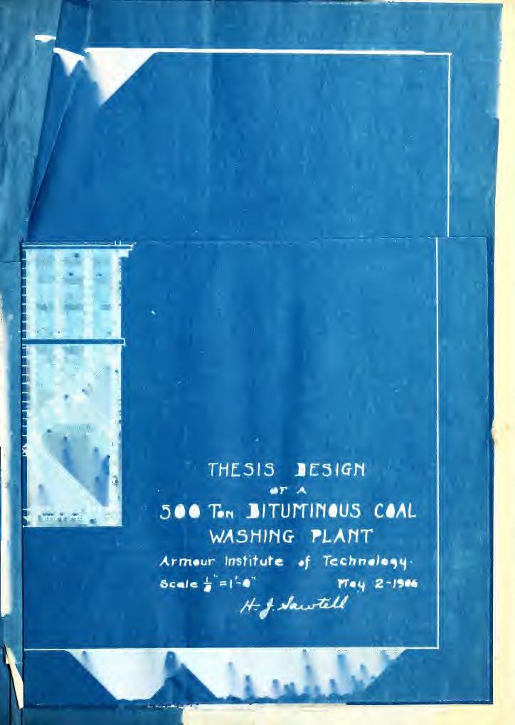
7 DESIGN 500 TON BITUMINOUS COAL. WASHING PLANT A THESIS PRESENTED BY H.J. Sawfell TO THE PRESIDENT AND FACULTY OF ARMOUR INSTITUTE OF TECHNOLOGY FOR THE DEGREE OF BACHELOR OF SCIENCE IN MECHANICAL ENGINEERING HAVING COMPLETED THE PRESCRIBED COURSE OF STUDY IN MECHANICAL ENGINEERING June I ILLINOIS INSTITUTE OF TECHNOLOGY PAUL V. GALVI-N LIBRARY 35 WEST 33RD STREET CHICAGO IL "^ft7x/\^
8


9 <SW7 a DESIGN OF A 50G TON BITUMINOUS COAL WASHING PLANT. THESIS EY HENRY JACOB SAWTELL, PRESENTED JUNE 19C6. To make the operation of the plant more easily understood, and to show the development reached in this work. short account of the action of the machines is here given with a short history tracing the development from the crude early machines to those now in use. The descriptions are necessarily brief. By coal washing is meant the process of separating the impurities with which the coal is mixed as it comes from the mine by means of special machines which use water as an accessory. The coal as it comes from the mine consists of coal proper^jand impurities, such as slate, sulphur in the form of pyrites or calcium, 'and magnesium sulphate, bone coal, and fire clay. With some exceptions these substances have a higher specific gravity than the pure coal, which is about 1.28 or 1.30, and it is this fact that makes their separation possible. The principle of the washer is demonstrated when two substances of different specific gravities are shaken together in a box. The heavier substance will settle in a flayer on the bottom, while the lighter substance will re-
10


11 main in a layer on top. This would not occur in a vacuum; water is a better medium than air. The method of washing to separate materials of different specific gravities is a very old one. It has been used in mining operations for a long time. In its use with precious metals the process is reversed, it being desired to save the heavier substance and get rid of the lighter. Almost every conceivable arrangement has been used; the process has been developed from the simple trough washer to the senfcative jigs. Some have tried air as the medium, others use centrifugal force, but none have proved as satisfactory as the jigging method. The simplest washer is known as a trough washer, and consists of an inclined trough with cross riffles at regular intervals. The coal is fed at the top and is given sufficient force by the water flowing down the trough to carry the coal over the riffles with it, leaving the slate on the recesses. At the bottom is a draining screen which separates the coal from the water. The slate is removed at intervals by an attendant with a rake. This is a very crude and imperfect method, and requires an excessive amount of water. An improvement on the simple trough washer is the Elliott trough washer. This consists of an inclined trough in which a flight conveyor operates. The coal and impurities are fed at the center of the trough. Water enters at the top. The flights on the conveyor act as the riffles,
12


13 3 the water washing the coal over the flights. The impurities are carried up the trough and are discharged at the top end. The coal passes down the trough to a receiving car, passing over a draining screen before it enters the car. The process is thus continuous and requires but little attention. Its marked simplicity is a feature, but a large quantity of water is required and the work, rather expensive because of its imperfect separation. Another washer along this line is known as the Scaife trough washer. This consists of an inclined semi-circular trough, about two feet in diameter, and twenty-four feet long, provided at intervals with riffles. Running along the center of the trough is a shaft provided with fingers which act as stirrers. The shaft is given a reciprocating motion. The raw coal is fed at the upper end. The impurities remain on the riffles, the washed coal being discharged at the lower end. When the riffles are full the supply of coal is shut off, the good coal remaining in the trough is washed off and the trough cleared by dumping the refuse into a box below. The process in intermittent, but the advantages claimed for it are its simplicity and the lack of a screen to wear out. The fingers or stirrers which are the only parts subject to much wear being easily replaced The Campbell bumping table consists of a shallow trough 2 l/2 x 8 ft. x about 6 or 8 inches deep, open at both ends. It is hung in an inclined position, and by
14


15 4 means of a cam is thrown against a bumping post at the upper end. The coal is sluiced on with water and as the bumping table is thrown against the post the impurities are thrown off the upper end while the pure coal is washed off the lower end with the water. The Robinson washer is of different construction. The coal and refuse are fed at the top of the vessel which is of the shape of an inverted cone. Water enters at the bottom with sufficient force to carry the coal over one side with it. The impurities settle in the bottom. A vertical shaft with stirring fingers attached keep;'the mass agitated thus allowing a better separation. An arrangement of German origin drops the raw coal past a blast of air which is of sufficient strength to force the pure coal to one side allowing it to drop into a bin. The impurities drop past into a refuse bin. A separation by means of centrifugal force has been used in the anthracite fields. A spiral trough is revolved to throw the slate in the coal, which is fed at the upper end, off the trough allowing the pure coal to slide down into a bin at the bottom. This is merely a rough separation. Jigs have to a large extent replaced the older methods of washing, being more economical and thorough. The Luhrig jig is typical and is widely used, giving excellent results with economical working. The two crosssections here shown are for nut and fine coal treatment. The nut coal jig consists of a box or chamber separated
16


17 4A i LUHRir. NUT OAL LUHRIG FELDSPAR JIG
18


19 5 - at about the center by a partition extending about half way down from the top. On one side is a plunger which is actuated by an eccentric through a connecting rod. On the other side is a screen on which the raw coal is fed. The screen is inclined, the coal being fed at the upper end. The plunger imparts a pulsating motion to the water which fills the entire box and this motion agitates the body of coal. The impurities being heavier settle in a layer on the bottom on the screen. The mass gradually works to the lower end where the coal is washed over the sill with the water. The impurities pass through an opening under the sill which is known as the slate valve. Below this slate valve is a conveyor trough into which the impurities fall and are carried by the screw conveyor to an elevator boot. The elevator raises the impurities to a trough or conveyor which leads to the refuse heap. This slate valve opening can be regulated so as to keep a uniform bed of impurities on the screen and thus prevent good coal from passing through the slate valve and being wasted. The coal is sized before being fed to the jig so that very little passes through the screen. Most of the material that does pass through the screen is very fine and is refuse, so a draining valve is placed in the bottom of the box to allow this waste material to be run off. This draining valve is connected to a sluice way which leads to the refuse settling tank. A continuous supply of water is fed at the rear of the jig through the pipe shown.
20


21 The fine coal jig is of about the same construction and operation, but differs in the manner of handling the waste materials. In these jigs it is necessary to handle coal from that which will pass through a 3/4 inch round perforation down to a fine dust. The box is divided as in the previous case with the plunger on one side and screen on the other. Cn the screen is placed a layer of feldspar which has a specific gravity higher than the coal, but lower that the impurities. The pieces have a diameter larger than the openings in the screen. The coal is fed in the same manner and works its way across the screen to the sill where it overflows with the water into the sluiceway in front. The refuse works its way through the layer of feldspar into the hoppered bottom of the jig box from where it passes through the refuse gate into a sluiceway by gravity and is carried to the refuse settling tank. These jigs can be placed in a battery up to twelve, so that one shaft and sluiceway will serve the entire battery. In the operation of these jigs it is very important that the coal treated in each jig be of uniform size. The Hartz jig is about the same as the above in general operation. It differs in construction, being made of sheet steel with semi-circular bottom. Berard's machine is another of similar operation. This machine was introduced as early as 1851 in London. It was used in Pennsylvania for a few years s» The Stutz jig has a few special appliances, the bottom
22


23 Till: STEWART TYPE UP J
24

25 THE STEWART TYPE OF JIG
26


27 being of special shape. In the improved machine the pulsating mechanism is placed directly under the screen on which the coal rests. A plant with this machinery capable of handling 6C0 tons per day of 1C hours has been estimated to cost $16C00.0C. The cost of washing has been given as 2 cents per ton, but this does not include interest and depreciation. The Stein jig has a special method of arrangement and handling the coal. The jigs, which resemble the others, are double. Coal is fed at the side of one jig. It passes over this bed to the next jig from which it is discharged into a sluiceway. There is thus obtained a long path and a thorough separation is accomplished. One result gives a reduction from 35^ to 1C$ ash and Z% to 1.35# sulphur. The Stewart jig operates a little differently than the others. This jig consists of a box with a perforated bottom which is suspended in a tank of water from eccentric rods by means of which it is given the pulsating motion. The bottom is inclined. The coal is fed at the upper end and works its way across the screen where it is washed over the sill with the water. The refuse passes through a valve in the front of the jig into the hoppered bottom of the jig from which it is discharged by an elevator. The coal that is fed to the jig is not sized. The capacity of each jig is higher than that of the Luhrig jigs, but with small size coal the operation is not as economical. The Diescher washer is similar to the Stewart. The 7

28

29 N'KW I'EXTUKY" N'UT COAL JIG
30


31
32


33 8 jig has a different shaped bed and has some variations in the mechanical construction. The special feature of the New Century jig is the plunger. By means of a spring a quick stroke is accomplished which seems to be very effective in separating fine coals. Luhrig, New Century, and Stewart type jigs are commonly used in the Illinois coal fields. In the selection of jigs for this plant the Luhrig type were selected because of the economical construction, operation and high efficiency The entire plant, in fact, has been equipped with Luhrig apparatus. The elevators with the exception of the raw coal, are Luhrig type. A cut here given shows the type of bucket and method of discharge. The buckets are perforated to allow as much water as possible to drain off before the coal is placed in the storage bin. This moisture remaining in the coal is a serious problem, and will be mentioned later. The head wheels are cast iron. The elevator is driven from the head-end by means of a chain-drive from a jack shaft. The speed reduction is accomplished by reducing from the jack shaft to a counter shaft and again by means of a spur and pinion from the counter to the head shaft. The head and counter shaft are supported on a Luhrig take-up which facilitates the fitting of the chain when construction or repairing. This take-up consists of a sole plate on which the bearings rest. They are spaced
34
35 LUHRIG ELEVATOR
36
37
38


39 9 to accommodate the gears and are held thus by a spacing rod. By means of a take-up screw both bearings are moved at the same time, thus allowing adjustment of the head wheel without disturbing the gears. The raw coal screen is shown by the sketch. It forms a compact and efficient method of grading the coal. Shaking screens are sometimes used, but they require more room and seem to have no greater advantages, altnough claimed by some to have. The screens are driven by means of gears and pinions. The jackets are supported by spider arms. The rinsing and resizing screens are all single jacketed. An important feature in coal washing is to have coal of uniform size fed to each jig. This is especially true of fine coal. The separation of the different sizes is nicely accomplished in the hydraulic grading box. This consists of a long box with honpered divisions across the bottom. The coal is sluiced into the box at one end, the larger sizes being heaviest settle in the first compartment and are sluiced to the first jig. The next size collects in the next compartment, and so on through the six grades. In this manner each jig can be regulated to a nicety to wash its product, and excellent results are obtained. An important feature of tne Luhrig system is the recovery of the sludge. In the older style washers the water used in the jigs was allowed to run off carrying with it much fine coal in the form of dust. Mr. Karl Luhrig saved this by allowing the water with the fine coal to pass into a large settling tank, known as the sludge tank.
40


41 1C The fine coal is here allowed to settle. A slowly moving conveyor then carries it to an elevator pit located at one end of the tank. At the end opposite to that at which the elevator is located is the suction pipe for the centrifugal circulating pump. The water at this end is clear enough to allow its use in the jigs. The water is thus used over and over again. The only water that is lost is that which is used in sluicing away the refuse. Enough fresh water is added as rinsing water to counteract this loss and keep the quantity constant. Tie fjji-tf He. s /'? i. " In the design of this plant the following conditions are to be met. 5CC tons of raw coal are to be washed in 8 hours, washing the product from the mine that passes through a 3" round perforation producing 5 sizes of washed coal as follows: Size Percent Thro. Cver #1 Nut
42


43 1C The following is an analysis of the coal which is from the Illinois coal field and is taken as a basis for the design of the plant. In the raw coal there is 25$ ash, that is, in the coal passing through the 3" perforations. The coal analysed in specific gravity solution gives the following results: Raw coal #1 Sink 61$ Floats 7% Ash 24$ F. 19$ A.
44


45 11 into the hydraulic grading box. Each size of coal will be washed separately, two jigs being provided for #1, three for #2, two for #3, and six for #4 and 5. After passing through their respective jigs #1, 2, and 3 washed coal will be sluiced to draining screens located directly over bins for their storage. These draining screens will also act as resizing screens so that any coal that has been broken and is undersize will be separated here and pass with the water to a redraining screen where sizes over #4 will be separated and returned to the boot of the raw coal elevator. It will thus be allowed to take its proper place in the rewashing. The fine coal and water passing through the redraining screen will pass into the hydraulic grading box. From the grading box the uniform sizes will pass into the fine coal jigs, six in number, and be washed separately. The washed coal will pass over the sill of the jig and be sluiced to a large revolving screen. Jh-e sre.cn #4 will pass over A into a sluiceway leading to the boot of the Luhrig elevator which will carry it to the top and empty it into the bin. #5 which consists of much dust and fine [he. screen particles will pass through A with the water into the sludge recovery tank located directly beneath the screen. As the fine coal settles it will be carried to the elevator pit by a flight conveyor. A Luhrig elevator will lift the coal to the #5 bin.


46


47 12 The nut coal will be rinsed by a spray of water on the draining screens; #4 by a spray on the separating screen, and #5 by a spray on the coal as it is being lifted to the bin from the sludge tank. The refuse passing through the slate valves of the nut coal j^gs will be carried by a screw conveyor to the boot of a Luhrig elevator which will lift the slate to a sluiceway and by which it will be sluiced to the refuse heap. The impurities from the fine coal jigs will pass to a settling tank from which it will be elevated by a Luhrig elevator to the refuse sluiceway. The nut coal jigs will be connected with the refuse settling tank so that the fine particles passing with the impurities through the screen and settling in the bottom of the jigs can be run off when necessary. The water for the nut coal jigs will be taken from the end of the sludge tank opposite to that at which the elevator is located. It will be lifted by a centrifugal pump to the jigs. The pump will be belted to a pulley on the engine crank shaft. Fresh water for rinsing the coal will be supplied from an outside source and will be supplied to the screens by a steam pump. The sludge and settling tanks will be provided with large size drain pipes so that the water could be run out in case of a shut-down in winter. The building will be heated by steam. The various gates and valves will be provided with steam connections
48


49 13 to prevent their freezing in winter. The building will be lighted with electricity to allow night work. The raw coal storage bins will have a capacity of 200 tons, and the washed coal storage bins a capacity of 270 tons. SPECIFICATIONS. Revolving feeder and gate for raw coal bin. 1 Link-Belt revolving feeder, complete. Also 1 "Spellman" gate complete with levers, etc. for delivery of raw coal from bin to raw coal elevator. Raw Coal Elevator. One continuous bucket elevator 60 ft. centers for lifting coal from raw coal bin to raw coal sizing screen. This elevator is to be made up of 16" x 12" x 18" #10 steel continuous buckets, carried by double strand of 18" pitch bar link rolling chain, complete with necessary head, counter, and foot shafts, bearings, collars sprocket wheels, patent spur equalizing gears, driving pulley on countershaft, and sprocket wheel on foot shaft for driving revolving feeder, also flat steel track for chain. Raw Coal Screen. One triple jacketed revolving screen for raw coal, inner jacket 12 ft. long; middle jacket 11 ft. long, and outer jacket 10 ft. long, complete, with 5 15/16" rough turned screen shaft, spiders, rings, steel cone, and covering of l/4" plate with 3/4" round perforations, and
50


51 14 1" round perforations for outer anil middle jacket, respectively, and of 3/8" plate with 1 3/4" round perforations for the inner jacket, also bearing and countershaft with bevel gear drive. Nut Coal Jigs. Seven Luhrig nut coal jigs, complete with shafts, eccentrics, etc. These jigs to be in one battery. Refuse Elevator from Kut Coal Jigs. One #5 Luhrig elevator, 15 ft. centers, complete, with all necessary head, and foot mechanism, chain and buckets, angle guides, back lining, and driving countershaft with fittings. Nut Coal Draining Screens. Five 31''t. diameter x 6ft. long nut coal draining screens, complete, with bearings, spiders, and coverings of #10 plate - two to have 1 3/4" perforations, two to have 1" perforations, and one to have 3/4" perforations. Also one 3'C" x 6'C" screen with covering of #10 plate and 3/4" perforations for over size coal in redraining. These screens to be complete with counter shaft, etc. Fine Coal Jigs. Six Luhrig fine coal jigs, complete, with shafts, eccentrics, feldspar beds, etc. These jigs to be in one battery Fine Coal Draining Screen. One 4'0" x 10*0" revolving screen, complete, with shaft, bearings, spiders, rings, and covering of f/-lc steel plate with l/4" round perforations.

52


53 15 #4 Fine Coal Elevator. One,;'l Luhrig elevator, 38 ft. centers, complete, with all necessary head and foot mechanism, chain and bucket angle guides, back lining, and driving countershaft with fittings. Sludge Recovery. One conveyor, about 46 ft. horizontal centers, and 1C ft. vertical centers, complete, with necessary head, counter and corner shafts, bearings, collars, sprocket wheels, gears, and Sstrands of 730 chain, each 122 ft. long, fitted with 3/16" steel flights, having reinforcing angles and wearing shoes ;also necessary steel tracking. #5 Coal Elevator. One #4 Luhrig elevator, 55 ft. centers, complete, with head and foot mechanism, chain and buckets, angle guides, back lining, and driving countershaft with fittings. Fine Coal Refuse Elevator. One #4 Luhrig elevator, 43 ft. centers, complete, wit$i head and foot mechanism, chain and buckets, angle guides, back lining, and driving countershaft with fittings. Gates for Washed Coal Bins. Five Link^Belt steam- jacketed gates, complete. Bin and Sluice Lining. Necessary #12 steel plate linings for bottoms of raw and washed coal bins; #12 steel lining for chutes, and #14 steel lining for sluiceways. Pumps One #8 Morris Imperial standard double suction
54


55 16 horizontal pump, complete, with pulley, for circulating water for jigs. Cne #25-7" x 5" x 10" "Gardner" low service duplex steam pump for fresh water. Piping. Necessary piping, with valves and fittings, from sludge recovery to pump, and to jigs, grading box and refuse sluice. Necessary piping from fresh water pump to sludge recovery, draining screens, and to refuse sluice. Steam piping to steam gates from steam lire in engine room. Also steam piping to steam coils for heating building. Necessary 12" vitrified sewer pipe for draining sludge and refuse pits Engine, Line Shaft, etc. Cne 13" x 18" double class "A" H. S. & G. #122 horizontal engine, 160 R.P.M., 130 H.P., with 80 lbs. steam pressure, complete, with usual fittings, and a 90" 4-groove split flywheel, sheave for 1 3/8" manila rope, also pulley for driving centrifugal pump. Necessary line shafting, jack shafting and countershafting, with rope transmission to main shaft, rubber belt to jack shafts and chain connection to the various appurtenances, elevators, conveyors, screens, etc.

56


57 17 Building. The lumber used for the building will be #1 common yellow pine, and for hart tc.i lumber of suitable quality. All lumber to be surfaced four sides. The building, with the exception of the bins, and sludge tank, will be covered with drop siding and complete with corner fc>oar<ls,window casing, frieze, etc. The roofing will be 2-ply composition, and necessary gutters will be provided. The building to be complete with all necessary doors, windows, and stairways, the windows being glazed. All exposed wood work is to be painted With the building are to be provided all necessary timber supports for machinery, and all necessary tanks, chutes, sluiceways, elevator casings, etc. Foundations are to be concrete. Many coals of poor quality in the raw state are made excellent fuel coals be washing, others of low quality and value are relatively increased. The substances that go to make up the ash in the furnace are removed by washing. It is thus that the quality is increased. As coal is now bought to a large extent on the heat unit basis it behooves the coal operators to have as small a percent of ash as possible By the removal of the impurities which to a large extent form the clinker in the furnace, such as pyrites and clay, the capacity of the furnace is often increased.

58


59 18 Another advantage of washed coal is that it is of uniform size when delivered, which is also condusive toward an increased furnace capacity by giving a uniform fire bed. In the manufacture of coke the treatment of the coal is an important matter. Coal of excellent coking qualities, but which contains too much ash or an excess of sulphur can often be improved by washing to make a very high-class coke. In the design of this plant the coal has been treated only with reference to boiler fuel. One disadvantage encountered in the treatment of coal is the amount of water that is retained by the coal, especially by the #5 size. It is very difficult to lower the percent of water which is often as high as lc^jwhere the coal has plenty a chance to drain, as in being transported quite a distance the coal drains quite thoroughly in the large sizes. The percentage of water above given includes the water that is contained in the pores of the coal as it comes from the mine. Often this runs as high as &fo. The water added from washing remains on the outside and drains off quite readily in the large sizes, but the #5 size contains so much fine stuff that it packs very close and holds the moisture. Attempts have been made to reduce the moisture but have as yet been unsuccessful in most cases, the treatment being too expensive. In the preparation of this paper much valuable information has been obtained from Mr. A. J. Sayers, of the Link- Belt Machinery Company, Chicago; John Fulton's book on Coke
60


61 has been found to be very instructive, as well as Richards' on Cre Dressing. The plant and mine of the Consolidated Coal Company, at Collinsville, Illinois, was visited. This plant is of about the same capacity and general arrangement as the one given in this design, employing Luhrig apparatus. At East St. Louis, Illinois, the plant of the Bessemer Washed Coal Company was inspected. This plant washes coal which the operators buy from the mines in ixrethe Illinois coal fields. The mine owners.often glad to get rid of the slack which can be washed and sold at a profit. This plant uses the Stewart type jig with Luhrig recovery. From the descriptions here given the importance of coal washing can be seen, as also the magnitude to which it has now developed. As the better beds of coal are used up the treatment of the poorer grades to make them fit for market b washing is bound to occur. In prepairing the design of this plant it was first attempted to have the machinery arranged to allow for expansion. As an entirely new equipment would be necessary, and also alterations in the entire plant, it was thought that it would be better to have a nearly independent plant than to try to arrange any additions. As the Stewart jigs have a larger capacity than Luhrig, and with large size coal they are quite as economical as the Luhrig, it was thought at first to install a fewer number of nut coal jigs by using the Stewart type. It was found, however, that this had been tried, but had not been particularly successful, so this 19
62


63
64


65 ht.,
66 I


67 20 hrig y has per s at are the Company ;n and led as n ns of hold full quired 11 Fting at

68


69 HI U

70


71 20 was dropped and the entire plant equipped with Luhrig apparatus. The plant of the Consolidated Coal Company has been operating for about a year, running sixteen hours per day, and is giving excellent satisfaction. No results are obtainable as to the efficiency of the plant as yet, but the fact that it was installed by the Link-Belt Machinery Company will insure a high mark. Calculations In the design of this plant the speed of the screen and elevators, and sizes of jigs, tanks, etc, were determined as far as possible from results found to be satisfactory in practice Raw Coal Elevator. This elevator will be required to lii't about 6C tons of coal per hour, or 1 ton per minute. Each bucket will hold about 4C lbs buckets per minute. 40 Each bucket is 18" deep. 50 x 18 = 75 ft. per minute = speed required. Assuming this as 80^ of capacity, for full capacity a speed of about 100 ft. per minute will be required The head wheels being 36 inches in diameter, about 11 R.P.M. will be necessary. With the arrangement of shafting as shown there are 3 reductions between the line shaft at 150 R.P.M. and the head shaft at 11 R.P.M. With equalizing gears of 46.75" and 8" diameter the
72


73 With 24" and 36" sprockets on chain drive from jack shaft to countershaft the speed will be raised to 9S E.P.M. 36 x 66 = 99 R.P.M With 48" and 32" pulleys froir jack to line shaft the speed of 150 R.P.M. on line shaft will be met. 48 x 99 = The belt could be counted on to slip enough to give about 11 R.P.M. at head shaft. Raw Coal Screen. 80^ of coal will pass through first screen, which equals 48 tons, allowing 4.3 sq.ft. per ton hour; Screen is 12 ft. long. 48 x 4.3 = 2C6 sq.ft. required. 2C6 = 5.5 ft. = diameter. TT x 12 57% will pass through next screen;.57 x 120CCC. 684GC lbs = 34.2 tons per hour. Allowing 6 l/2 sq.ft. per ton hour x 6.5 = 222 sq. ft. of screen; second screen 11 ft. long ft. diameter. 11 x / will pass through third screen..48 x 1200CC = 576CC lbs. = 28.8 tons per hour. Allowing 8.7 sq. ft. per ton hour 28.8 x 8.7 = 25C sq. ft. screen. Screen is 10 ft. long. 250 = 8 f t. diameter. 10 x 3.14
74


75 22 With screen running at 9 R.P.M. a peripheral speed of 226 ft. per minute is reached. To obtain 9 R.P.M. at screen three reductions are used: 66_i52_x_9_ =52.5 R.P.M. speed of countershaft and = diameters of gear and pinion respectively. Belt to jack shaft x 38 = 100 R.P.M. speed of jack 20 shaft - 38 and 20 = diameters of pulleys. Eelt to line shaft: 48_x_ 1CC_ = 150 R.P.M. - speed of line 32" shaft. 48" and 32" - diameters of pulleys. Nut Refuse Elevators. From 100 R.P.M. on jack shaft to 6 R.P.M. of head shaft through two reductions: 24 x 48 = 11.5" diameter of the 100 sprocket on jack shaft. 2 4 x 9.55 = 39.63" diameter of 6 spur gear on head shaft. Fine Coal Elevators. Using same gears as above. Then it is necessary to reduce from 150 to 24 through two reductions. 150 on line shaft to 81 on jack shaft - 81 on jack to 24 on counter shaft. 24 x 48 = 14 l/4" diameter of jack shaft sprocket x 24 = 45" = diameter of pulley on line shaft. «1
76


77 23 Nut Goal Jigs. 75 R.P.M. of eccentric shaft frorr 150 on line shaft. 150 = ratio 2 to 1, which can be had by using 26 and inch pulleys. Fine Goal Jigs. 125 R.P.M. of eccentric from 150 R.P.M. of line shaft ratio of 6 to 5, which is given by 36 and 30 inch J25 pulleys Resizing Screens. 150 R.P.M. on line shaft to 22.5 through two reductions 150 x 22 = 69 R.P.M = ratio of 3 to 1 for bevel gears, which is obtained and 5.09 inch diameters resp. #4 and #5 Screens. 150 R.P.M. to 15.7 R.P.M. through two reductions: 16 x 150 = 60 R.P.M.; 16 and 40 inch.* diameters of 40 pulleys x 60 = 15.7 R.P.M.; and 45 inch. = the di- 45 ameters of sprockets. 4 x 3.14 x 15.7 = 197 ft. per minute peripheral velocity of screen. Scraper Conveyor. 60 R.P.M. of jack shaft to 4 R.P.M. of scraper shaft through two reductions.

78


79 60 x = 26.7 R.P.M.; and 25 inch. = diameters of 25 bevel gears x 26.7 = 4 R.P.M. ; 7.24 and 47.9 = diameters of pinion 47.9 and spur gear. /=" e cj f At 11 R.P.M. 66 buckets will be filled per minute. With three divisions on feeder 66/3 r 22 R.P.M. necessary. 24 Foot shaft runs at 11 R.P.M., which gives a ratio of 2 to 1. With 30 and 15 teeth on sprockets this ratio is obtained; sprockets are 24 3/4" and 12 l/2" in diameter resp. The horse power supplied is very liberal, but as fuel is a small item it was deemed best to allow plenty of power. The power will be used as follows Each jig has been allowed 1.75 B.P. 13 jigs will require 15 x 1.75 = H.P. Each small elevator has been allowed 5 H.P. 4 elevators require 20 H.P. For the centrifugal pump 1 H.P. has been allowed for each foot lifted, which is 30. For the raw coal elevator 10 H.P. has been allowed. Then allowing 20 H.P. for the screens, shafting and scraper conveyor a total of 103 H.P. is reached. The H. S. & G. Company's nearest size would be 50 H.P. which when placed double would give 100 H.P. It would be necessary to run overload with this size so the next size was selected which is 65 H.P. giving 130 H.P. when placed double. The engine is not protected by placing it in an enclosed room so that it is subjected to quite rough treatment; thus an excess of power at the start is not unreasonable.

80
81
82

83


84

85

86
Rockmaster Super Black Diamond Black Diamond Cobra SINGLE ROLL CRUSHERS
 S I N C E 1 8 3 5 Rockmaster Super Black Diamond Black Diamond Cobra SINGLE ROLL CRUSHERS SINGLE ROLL CRUSHERS Why use a Single Roll Crusher? 1. The single roll crusher reduces large size particles in
Coarse Material Washers & Blade Mill Aggregate Washers FROM
 Coarse Material Washers & Blade Mill Aggregate Washers You can count on GreyStone Coarse Material Washers and Blade Mill Aggregate Washers to help you turn material washing problems into profitable solutions
Aurora Consolidated Mines Company records. No online items
 http://oac.cdlib.org/findaid/ark:/13030/c8ht2tvb No online items Finding aid prepared by Jessica Kim. Manuscripts Department The Huntington Library 1151 Oxford Road San Marino, California 91108 Phone:
Household devices, <-<>al breaker rolls, stone crusher, four early types of power devices.
 SECTION VI Nos. 81 06 Household devices,
ADJUSTMENTS FOR EFFICIENT AND PRECISION SEED CLEANING James Henderson Y
 ADJUSTMENTS FOR EFFICIENT AND PRECISION SEED CLEANING James Henderson Y One of the recent developments that has contributed to more efficient and exact seed cleaning is the metering hopper for screen and
Quality & Service Since For the Reduction of Metal Turnings to Shoveling Chips for Briquetting or Pneumatic Conveying
 Quality & Service Since 1908 For the Reduction of Metal Turnings to Shoveling Chips for Briquetting or Pneumatic Conveying Features & Benefits Why it will pay you to have our Metal Turnings Crusher in
PRINCIPLES OF GRAVITY SEPARATION Jim Thomas. Engineer Oliver Mfg. Company Rocky Ford, Colorado
 PRINCIPLES OF GRAVITY SEPARATION Jim Thomas Engineer Oliver Mfg. Company Rocky Ford, Colorado All gravity separators utilize the same principles to effect a separation. Once these principles are understood,
Boiler Draft Equipment
 Boiler Draft Equipment Learning Outcome When you complete this module you will be able to: Discuss, sketch and describe the basic equipment used to supply combustion air to a boiler furnace. Learning Objectives
B.Tech. First Semester Examination Basics of Mechanical Engineering (ME-101F)
") B.Tech. First Semester Examination Basics of Mechanical Engineering (ME-101F) Q. 1. (a) Differentiate between water tube boiler and fire tube boiler. Ans. Comparison Between 'Fire-tube and Water tube'
B.Tech. First Semester Examination Basics of Mechanical Engineering (ME-101F) Q. 1. (a) Differentiate between water tube boiler and fire tube boiler. Ans. Comparison Between 'Fire-tube and Water tube'
CYBAS-i Cone High Performance Cone Crushers
 CYBAS-i General Dimensions CYBAS-i Cone High Performance Cone Crushers O + ) 2 8 8 IMS Engineering (Pty) Ltd Physical Adress: 10 Derrick Road, Spartan, Kempton Park, 1625 South Africa Postal Address: PO
Tel Group
 www.wamechsi.com Tel +27 12 808 0682 sales@wamechsi.com VERTICAL SHAFT, LOW SPEED, AERATORS Technical Specifications Vertical shaft, low speed aerators are ideal for the bacterial oxidization of effluent
ANNEXURE-A SPECIFICATIONS FOR HOT MIX PLANT
 ANNEXURE-A SPECIFICATIONS FOR HOT MIX PLANT COLD AGGREGATE BIN FEEDER FEEDING HOPPERS Four Nos. Cold aggregates hopper with a heaped capacity of approx. 52 T. Wide opening bin width to accommodate different
HUBER Grit Separation Systems
 WASTE WATER Solutions HUBER Grit Separation Systems Reliable Complete Plants for separation of screenings and grit A range of grit trap systems for separation of mineral particles The optimally suitable
Pumps SELECTION OF A PUMP
 Pumps SELECTION OF A PUMP A water system needs to move the water produced from the source to its customers. In almost all cases in Minnesota, the source is at a lower elevation than the user so the water
PART II. THE PRECLEANING OF PADDY
 PART II. THE PRECLEANING OF PADDY Prior to the actual milling operation, the paddy received from the farmer is cleaned in precleaning machines. Foreign matter or impurities are removed to protect the processing
Sanitise Syrup Lines & Valves. Taylor PH61 Cleaning every 14 days
 Taylor PH61 Cleaning every 14 days Drain the Syrup Lines Remove each syrup feed tube from syrup bottle and let excess syrup drain from the feed tube back into the syrup bottle. When flow of syrup from
STEAM TRAPS FOREST PRODUCTS LIBRARY FOREST RESEARCH LABORATORY OREGON STATE UNIVERSITY. Information Reviewed and Reaffirmed. August No.
 STEAM TRAPS FOREST PRODUCTS LIBRARY FOREST RESEARCH LABORATORY OREGON STATE UNIVERSITY Information Reviewed and Reaffirmed August 196 No. 1664 11111111111134 areillin1111111 1 11111111 1 1[1 11 nin FOREST
The equipment and materials shall be designed and constructed in accordance with the ASME code section I 2001 ED A02 and Chinese Standards.
 Steam Boiler Type S50-3.82/450 Traveling grate stoker 50t/h x 3.82 pa x 450 Degree C 1. Basic use of the boiler The boiler can be used for industrial power generation, or thermal power station for enterprises
VENCO - STANDARD PUGMILL ( NON DE-AIR )
") VENCO - STANDARD PUGMILL ( NON DE-AIR ) AVAILABLE SIZES: 75mm (3") nozzle 136m (5.3") barrel 180kg/hr (400lb/hr) production Hopper opening 115x100mm [4½x4 ] L x W x H [crated] 1.08 x 0.34 x 0.37 m [43
VENCO - STANDARD PUGMILL ( NON DE-AIR ) AVAILABLE SIZES: 75mm (3") nozzle 136m (5.3") barrel 180kg/hr (400lb/hr) production Hopper opening 115x100mm [4½x4 ] L x W x H [crated] 1.08 x 0.34 x 0.37 m [43
Crushing Plant--ZYS High-Efficient Cone Crusher
 Crushing Plant--ZYS High-Efficient Cone Crusher >> E-Mail:joyal@crusherinc.com >> Http://www.joyalcrusher.com Shanghai Joyal Mining Machinery Co., Ltd ZYS High-Efficient Cone Crusher Profile The JOYAL
BITUMINOUS DIGITRAC AUTO STABILITY PRESS MARSHALL AUTOMATIC DIGITAL TESTER MARSHALL TESTING MACHINE W/ RECORDER MODELS
 18 BITUMINOUS DIGITRAC AUTO STABILITY PRESS The DigiTrac stability press for the Marshall method allows the operator to initially set up the platen and then the load and flow values are digitally tracked
INSTALLATION AND MAINTENANCE OF THE "THOMPSON-BRITISH" AUTOMATIC PLATEN
 INSTALLATION AND MAINTENANCE OF THE "THOMPSON-BRITISH" AUTOMATIC PLATEN Installation and Maintenance of The "Thompson-British" Auto Platen Lifting Bolt. Motor. Direction of rotation. Oiling. The machine
SAVI MultiRake Perforated Plate Screen
 HEADWORKS SCREENS FSM Filterscreen FRSIII Perforated Plate Belt Screen Highest Screenings Capture Ratio at 85% as verified by ThompsonRPM testing. Self-adjusting cleaning brush mechanism eliminates manual
MOP WRINGER MODEL RS-31 MODEL RS-31V
 103 W. Weaver Street, Carrbor NC 27510, USA www.skimoil.com / contact@skimoil.com (314) 579-9755 MOP WRINGER MODEL RS-31 MODEL RS-31V The compact RS-31 oil skimming system is ideal for industrial applications
BIOGAS BIOGAS AGITATORS. Our product range for increased biogas production
 BIOGAS AGITATORS Our product range for increased biogas production For closed concrete digester For mounting through wall or roof Giantmix FR Propeller Agitators The Giantmix FR has been specially designed
RHGN-H: COMMERCIAL AIR HANDLER WITH VARIABLE FREQUENCY DRIVE (VFD) NOMINAL 10 TONS R-410A REFRIGERANT 2-STAGE AIR-FLOW
 NOMINAL 10 TONS R-410A REFRIGERANT 2-STAGE AIR-FLOW") INSTALLATION INSTRUCTIONS RHGN-H: COMMERCIAL AIR HANDLER WITH VARIABLE FREQUENCY DRIVE (VFD) NOMINAL 10 TONS R-410A REFRIGERANT 2-STAGE AIR-FLOW 92-106595-01-00 TABLE OF CONTENTS Introduction.......................................
INSTALLATION INSTRUCTIONS RHGN-H: COMMERCIAL AIR HANDLER WITH VARIABLE FREQUENCY DRIVE (VFD) NOMINAL 10 TONS R-410A REFRIGERANT 2-STAGE AIR-FLOW 92-106595-01-00 TABLE OF CONTENTS Introduction.......................................
JHT, JXT JAW CRUSHERS
 JHT, JXT JAW CRUSHERS JXT JAW CRUSHER Blockage CLearance/Tramp Iron Relief System clears chamber of uncrushables Heavy-duty crusher for all applications JHT JAW CRUSHER Heavy-duty crusher designed for
NEW. Tundra LTX Hydraulic Pump. Reliable liquid manure transfer system from Patz. Let Patz handle your manure so you don t have to!
 Tundra LTX Hydraulic Pump Reliable liquid manure transfer system from Patz. The Tundra LTX Pump will go great lengths to work for you! Transfers liquid manure up to 2000 ft. and pumps up to 227 GPM. Works
INDIVIDUAL DRIVE, CHAIN DRIVE AND U- SEAL MECHANISM IN ROLLER HEARTH NORMALISING FURNACE
 INDIVIDUAL DRIVE, CHAIN DRIVE AND U- SEAL MECHANISM IN ROLLER HEARTH NORMALISING FURNACE Akash Kumar Mechanical Engineering Dronacharya College of Engg. Gurgaon, Haryana Abstract:- This project deals with
SOLVING WINDMILLING PROBLEMS ON BELT ACHE FAN SYSTEMS
 SOLVING WINDMILLING PROBLEMS ON BELT ACHE FAN SYSTEMS HOW TO IMPROVE WORKER SAFETY AND REDUCE MAINTENANCE Introduction If your solution to stopping a back-spinning ACHE fan is to apply your hand to the
PAN. Horizontal Blenders PROCS I AMERICAN SYSTEMS. Packaging - Processing Bid on Equipment
 PAN Horizontal Blenders PROCS I AMERICAN SYSTEMS Packaging - Processing Ribbon Blenders-Type DRB Two APS Model DRB-55 Sanitary Ribbon Blenders with low pressure heating jackets. Ribbon Blenders provide
HEADWORKS PERFORATED PLATE FILTER SCREEN ROTARY DRUM SCREEN IN CHANNEL PERFORATED DRUM SCREEN
 HEADWORKS PERFORATED PLATE FILTER SCREEN The Filter Screen eliminates operational disruptions caused by fibrous and other inorganic material. Depending on the perforated panel, the screening capture rate
ROTARY DRYER CONSTRUCTION
 ROTARY DRYER The Rotary Dryer is a type of industrial dryer employed to reduce or to minimize the liquid moisture content of the material it is handling by bringing it into direct contact with a heated
batch Chargers I N N o V a t I o N e N g I N e e r e d I N g e r M a N Y
 batch chargers INNOVatION ENGINEERED IN GERMANY Batch Charger Model HVR F General The HVR batch charger is used for fuel fired furnaces with lateral or frontal, open doghouses Level control If the batch
CrossFlow Separators: An Overview
 CrossFlow Separators: Maple Creek Coal Preparation Plant An Overview OUTLINE CrossFlow Separator Introduction Testing CrossFlow: Coal Advantages What is the CrossFlow? Conventional Cross-Flow Feed Feed
COOLING SYSTEM 1. Section V CONTENTS DATA AND SPECIFICATIONS. Page. Fluid Fan Drive (Silent Flite) 3. Water Pump 4. Radiator 5
 3. Water Pump 4. Radiator 5") Section V COOLING SYSTEM CONTENTS Fluid Fan Drive (Silent Flite) 3 Water Pump 4 Radiator 5 Water Temperature Gauge 6 Thermostat 7 Radiator Pressure Cap 7 Service Diagnosis 7 DATA AND SPECIFICATIONS COOLING
Section V COOLING SYSTEM CONTENTS Fluid Fan Drive (Silent Flite) 3 Water Pump 4 Radiator 5 Water Temperature Gauge 6 Thermostat 7 Radiator Pressure Cap 7 Service Diagnosis 7 DATA AND SPECIFICATIONS COOLING
C&W specializes in dust control for a variety of sand-related applications.
 Dust Control for Sand Operations C&W specializes in dust control for a variety of sand-related applications. We have expertise in various sand applications ranging from sand blasting, drying, classifying,
Variable speed hydraulic coupling and drive unit of hydraulic coupling
 Variable speed hydraulic coupling and drive unit of hydraulic coupling I. Model designation YO / / / Modificait on code Output speed of drive unit (r/min) Input speed of coupling or drive unit (r/min)
Agitation and Mixing
 Agitation and Mixing Agitation: Agitation refers to the induced motion of a material in a specified way, usually in a circulatory pattern inside some sort of container. Purpose is to make homogeneous phase.
Crushers, Mills and Stock Treatment
 Chapter Crushers, Mills and Stock Treatment 11 Crushers (CR)... 11-3 Flakers (FL)... 11-6 Mills (M)... 11-7 Stock Treatment (ST)... 11-8 G2 ICARUS Corporation, 1998. 11-2 ICARUS Reference ICARUS Corporation,
State of Nevada Department of Transportation Materials Division METHOD OF TEST FOR EVALUATING CLEANNESS OF COARSE AGGREGATE
 State of Nevada Department of Transportation Materials Division Test Method Nev. T228C METHOD OF TEST FOR EVALUATING CLEANNESS OF COARSE AGGREGATE SCOPE The cleanness test provides an indication of the
HOW TO SELECT AN INDIRECT THERMAL TECHNOLOGY FOR INDUSTRIAL MATERIALS PROCESSING
 white paper HOW TO SELECT AN INDIRECT THERMAL TECHNOLOGY FOR INDUSTRIAL MATERIALS PROCESSING Better Thermal Processing Results Begin with Selecting the Right Technology Authored by Rob Grady Director of
SERVICE MANUAL. For Service & Parts please call APK THERMAL at or SAFETY INSTRUCTION
 SERVICE MANUAL Installation, Operation and Maintenance Manual for Standrd Pre-Engineered Shell & Tube Models BCF, HCF, HFF, SSCF & SX2000 Fixed Tube Sheet Heat Exchangers For Service & Parts please call
HUBER Grit Separation Systems
 WASTE WATER Solutions HUBER Grit Separation Systems Reliable Complete Plants for separation of screenings and grit A range of grit trap systems for separation of mineral particles The optimally suitable
Series 300 VTB. Installation Instructions
 Series 300 VTB Installation Instructions Sizes 7 12 16 20 30 HP #2 Fuel Oil Gas (500 to 2500 BTU) Gas Light Oil Combination High Pressure Steam Sizes 7 thru 16 HP (125 PSI) Sizes 20 and 30 HP (150 PSI)
PIPING SYSTEM EQUIPMENTS
 PIPING SYSTEM EQUIPMENTS Introduction Equipments are devices that provide power, process and store materials. Equipments in piping systems depend on the specific industries using them. Specialized equipment
Wet Frac Sand Processing
 Wet Frac Sand Processing Meeting the Demands of a Growing Market Oilfield Minerals Outlook, June 21, 2012 CHRISTOPHER KELLEY Sales Manager Objectives of Wet Frac Sand Processing - Liberate Individual Silica
OTO BONDER OWNER S MANUAL WITH CIRCULATING SYSTEM MACHINERY DIVISION - - L to R Unit Shown
 GBAC RROTO OTO BONDER BONDER WITH CIRCULATING SYSTEM G B MACHINERY DIVISION OWNER S MANUAL L to R Unit Shown - - IMPORTANT FOREWORD 1) To ensure efficiency, the GBAC must be properly maintained. Carefully
State of Nevada Department of Transportation Materials Division METHOD OF TEST FOR EVALUATING CLEANNESS OF COARSE AGGREGATE
 State of Nevada Department of Transportation Materials Division METHOD OF TEST FOR EVALUATING CLEANNESS OF COARSE AGGREGATE SCOPE The cleanness test provides an indication of the relative proportions of
PREMIER SERIES BY P1255RBL-18 P2339RBL-18
 PREMIER SERIES BY P1255RBL-18 P2339RBL-18 P2339RBL-18 P1255RBL-18 P2339RBL- P1255RB- P2339RBL- 1. P2339RBL 18 Machine casting components Line Part Number Description Qt. Notes 1 300 1002 Machine
Hakki Pilke Raven spare parts manual
 1 ENGLISH Hakki Pilke Raven spare parts manual Valimotie 1, FI-85800 Haapajärvi, FINLAND Tel. +358 8 772 7300, Fax +358 8 772 732 info@maaselankone.fi, www.maaselankone.fi 2 Table of contents 1 Upper section
ARCHIVE GUARDING OF PAPER BALING PRESSES
 GUARDING OF PAPER BALING PRESSES NOTE The technical information in this book was current at the time of printing in 1984. While the guarding principles are still valid, the information does not necessarily
PACKAGED COMMERCIAL WATERTUBE BOILERS
 PACKAGED COMMERCIAL WATERTUBE BOILERS PACKAGED COMMERCIAL WATERTUBE BOILER American Boiler Manufacturers Association 4001 N. 9 th Street, Suite 226 Arlington, VA 22203-1900 703/522-7350 2003, American
C. ASSE 1013: Performance Requirements for Reduced Pressure Principle Backflow Preventers.
 SECTION 22 10 00 PLUMBING PIPING AND PUMPS PART 1 - GENERAL 1.1 Purpose: A. This standard is intended to provide useful information to the Professional Service Provider (PSP) to establish a basis of design.
LIQUID/SOLID SEPARATION
 LIQUID/SOLID SEPARATION Headworks Screens Screening Systems Grit & Solids Management HEADWORKS SCREENS SAVI Flo-MultiRake Medium-Duty GVB- Coarse Bar Screen GVF- Fine Bar Screen GVS- Perforated Media Screen
APPLICATION PROFILE EXPLOSIONS IN CEMENT PLANTS EXPLOSIONS IN CEMENT PLANTS CEMENT PLANT EQUIPMENT WITH HIGHEST EXPLOSION POTENTIAL. Form No.
 APPLICATION PROFILE EXPLOSIONS IN CEMENT PLANTS Cement manufacturing is one of the largest mineral commodity industries in the United States, with an estimated production capacity of greater than 73 million
OCEANO BOTTLE WASHER
 OCEANO BOTTLE WASHER OCEANO In the effort to reduce the environmental impact of waste from industrial production, there is an increasingly deeplyfelt need to recover empty containers, such as glass or
PREVIEW COPY. Pumps. Table of Contents. Pump Development and Application...3. Basic Pump Hydraulics End-Suction Centrifugal Pumps...
 Pumps Table of Contents Lesson One Lesson Two Lesson Three Pump Development and Application3 Basic Pump Hydraulics19 End-Suction Centrifugal Pumps35 Lesson Four Propeller and Turbine Pumps51 Lesson Five
Evaluation Report 521
 Printed: February, 1987 Tested at: Portage la Prairie ISSN 0383-3445 Group 1(a) Evaluation Report 521 Forever 42 Dustless Grain and Grass Seed Cleaner A Co-operative Program Between ALBERTA FARM MACHINERY
The equipment for storage and transportation of grain
 The equipment for storage and transportation of grain About Company Grain House Сompany is a manufacturer of grain bins and wide range of material handling equipment in Ukraine. Grain House main partner
following distribution into ampoules led to the development of the freezing
 MACHINE FOR SHELL FREEZING SM\IALL VOLUMES OF BIOLOGICAL PREPARATIONS L. D. ANTOINE AND M1. V. IIARGETT United States Public Health Service, Rocky illountain Laboratory, IIamnilton, Montana Received for
Mixers and Flocculators. For Municipal Water Treatment
 Mixers and Flocculators For Municipal Water Treatment Equipment for Enhanced Mixing and Flocculation We manufacture a wide range of mechanical mixers and flocculators designed to enhance the performance
Selecting the Correct Fan
 Selecting the Correct Fan Ryan B. Johnson Air Purification Company Sales Engineer Member, ASHRAE Pikes Peak Chapter rjohnson@airpurificationcompany.com 1 Your Speaker circa 1998 Fan Types Applications
Cages for Laying Hens. Our Experience. Your Success. Count on Chore-Time for experience, reliability, performance and confidence.
 Cages for Laying Hens Our Experience. Your Success. Count on Chore-Time for experience, reliability, performance and confidence. Modular Manure Belt (MMB ) Laying System 3-High to 12-High Systems Ultra
EuroPEK Oil Separator
 www.wavin-labko.fi WAVIN-LABKO LTD Labkotie 1 FIN-36240 KANGASALA Tel: +358 20 1285 270 Fax: +358 20 1285 280 E-mail: tanks@wavin-labko.fi 01/04 EuroPEK Oil Separator Instructions for Installation, Operation
engineered for a higher return
 engineered for a higher return We don t spend a lot of money keeping them running, and they ve been running hard and long. Lavatec Laundry Technology includes: Continuous Tunnel Washers Washer Extractors
1.1 This section applies to air handling units for HVAC Systems.
 AIR HANDLING UNITS GENERAL INFORMATION 1.1 This section applies to air handling units for HVAC Systems. DESIGN REQUIREMENTS 2.1 Design Criteria a. The decision to use modular central station air handling
HUBER Grit Separation Systems
 WASTE WATER Solutions HUBER Grit Separation Systems Reliable Complete Plants for separation of screenings and grit A range of grit trap systems for separation of mineral particles The optimally suitable
Paver Operation 101 Paving for Uniform Texture and Smoothness
 Paver Operation 101 Paving for Uniform Texture and Smoothness RMACES February 2016 Paver Operation 101 Paving By The Numbers Paving for Uniform Texture Paving for Ride Paving by the Numbers Step 1 Heat
Section - A Vacuum Feed Attachment
 Tray Box Former 1.0 Section - A Vacuum Feed Attachment A-1 Table of Contents SECTION NO. PAGE SECTION NO. PAGE A.0 INTRODUCTION PURPOSE... A-3 A.1 SET-UP AND ADJUSTMENTS FIGURE A-1 VACUUM FEED MOUNTING
Introduction to Bulk Solids. The Basics
 Introduction to Bulk Solids The Basics Glossary of Terms Angle of Repose This is the angle that material will naturally mound up when filling a tank, or down when discharging a tank. Dielectric Constant
Information on Feeder Systems ProMinent Australia
 Information on Feeder Systems ProMinent Australia Powders that ProMinent have provided packages for: Sodium fluoride Sodium silicofluoride PAC Soda ash Lime Alum Potassium permanganate Calcium Hypochlorite
Installation, Operation and Maintenance LOK-FLANGE Multitube Heat Exchangers
 Bulletin 1200/4 (Revised 5/12) Installation, Operation and Maintenance LOK-FLANGE Multitube Heat Exchangers INNOVATORS IN HEAT TRANSFER I. INSTALLATION OF HEAT EXCHANGERS A. HEAT EXCHANGER SETTINGS 1)
ProcessBarron is a leader in the design, fabrication, installation, maintenance, and repair of air, flue gas and bulk materials handling system
 Mechanical ProcessBarron is a leader in the design, fabrication, installation, maintenance, and repair of air, flue gas and bulk materials handling system equipment. From our production facilities near
METHOD OF TEST FOR PREPARATION OF MARSHALL SPECIMENS 3. APPARATUS. Canadian Council of Independent Laboratories June 2016 LS-261 R27 ASTM D
 3. APPARATUS 3.1 METAL CONTAINERS: Of sufficient capacity, required for heating aggregates... 3.2 MARSHALL MOULDS: Conform to details shown in Figure 1... 3.3 COMPACTION HAMMER: Hand Type... Total mass
Metso MX. Multi-Action cone crusher
 Multi-Action cone crusher Multi-Action cone crusher +10% more uptime -10% operational costs Up to 70% wear part utilization Multi-Action technology Selective production Safe and simple A giant leap in
Electro-Sensors is revolutionizing the way hazard monitoring is done, with its turnkey HazardPRO TM systems. Rugged sensors and the most advanced
 Electro-Sensors is revolutionizing the way hazard monitoring is done, with its turnkey HazardPRO TM systems. Rugged sensors and the most advanced wireless technology combine to create the best hazard monitoring
FAIRMOUNT WATER WORKS
 FAIRMOUNT WATER WORKS 1815-1911 A NATIONAL HISTORIC MECHANICAL ENGINEERING LANDMARK Philadelphia Water Department THE AMERICAN SOCIETY OF MECHANICAL ENGINEERS March 29, 1977 Fairmount Works, showing gears,
FORMATIC Instruction Manual
 FORMATIC Instruction Manual Gibson Street, Leeds Road, Bradford West Yorkshire, England. BD3 9TR Telephone: +44 (0) 1274 668771 Fax: +44 (0) 1274 665214 FORMATIC CONTENTS 1. Introduction 2. Technical Specification
SOLIDS FLOW SENSOR SOLIDS FLOW SENSOR: MWS-DP-2
 SOLIDS FLOW SENSOR AN INTRODUCTION TO: SOLIDS FLOW SENSOR: MWS-DP-2 Vr. 4.01 1. GENERAL 1.1 About WADECO s Microwave Flow Switch With over 25 years experience, WADECO is the world leader in the design
THE UNIVERSITY OF ILLINOIS LIBRARY
 THE UNIVERSITY OF ILLINOIS LIBRARY A STUDY OF CONCRETE MIXERS BY JOHN WILHELM SIMMONS Jr. THESIS FOR THE DEGREE OF BACHELOR OF SCIENCE IN CIVIL ENGINEERING COLLEGE OF ENGINEERING UNIVERSITY OF ILLINOIS
MIX Type Blenders. I Application. I Principle of operation
 MIX Type Blenders MSMIX I Application INOXPA's MIX type blenders have been designed specifically for mixing low or high viscosity liquid products for the food, cosmetics, pharmaceutical and chemical industries.
LIBRARY OF THE UNIVERSITY OF ILLINOIS AT URBANA-CHAMPAIGN. Y\o. GG - *33 SURVEY
 LIBRARY OF THE UNIVERSITY OF ILLINOIS AT URBANA-CHAMPAIGN Y\o. GG - *33 SURVEY ILLINOIS NATURAL HISTORY SURVEY BIOLOGICAL NOTES NO. 96 Urbana, Illinois, February 1976 STATE OF ILLINOIS DEPARTMENT OF
Pretreatment Applications. John Meunier Products and Solutions WATER TECHNOLOGIES
 Pretreatment Applications John Meunier Products and Solutions WATER TECHNOLOGIES 1 A long tradition in excellence John Meunier products have been serving North American municipalities and industries since
Heat Exchanger. The purpose may be either to remove heat from a fluid or to add heat to a fluid.
 HEAT EXCHANGERS Heat Exchanger Heat exchanger is an apparatus or an equipment in which the process of heating or cooling occurs. The heat is transferred from one fluid being heated to another fluid being
Lightweight Concrete Mix Profitable Using Heavyweight Batch Mixer
 DRY BULK BLENDING EQUIPMENT Rotary Batch Mixers Ribbon/Paddle/ Plow Blenders Rotary Continuous Blenders High Intensity Continuous Blenders Vee-Cone Blenders Fluidized Bed Mixers SIZE REDUCTION EQUIPMENT
Fans: Features and Analysis
 Technical Development Program COMMERCIAL HVAC EQUIPMENT Fans: Features and Analysis PRESENTED BY: Michael Ho Version 1.2 Menu Section 1 Section 2 Section 3 Section 4 Section 5 Section 6 Section 7 Section
BLAST-IT-ALL BUMPER BLASTER
 LARRY HESS AND ASSOCIATES, INC 185 PIPER LANE / SALISBURY, NC 28147 PHONE: 1-800-535-2612 / FAX: 1-704-638-9311 WWW.BLAST-IT-ALL.COM BLAST-IT-ALL BUMPER BLASTER SUCTION BLAST CABINET NOTE: It is the responsibility
INSTALLATION, OPERATION, AND MAINTENANCE MANUAL
 INSTALLATION, OPERATION, AND MAINTENANCE MANUAL TUBE AXIAL FANS BTA, WTA, HTA, DDA The purpose of this manual is to aid in the proper installation and operation of the fans. These instructions are intended
SECTION AIR COMPRESSORS AND ACCESSORIES
 PART 1 GENERAL 1.01 WORK INCLUDED SECTION 11370 AIR COMPRESSORS AND ACCESSORIES A. This specification includes air compressors with air dryers. B. Furnish, install, start-up, and test air compressors and
CENTRIFUGAL PUMPS. STATE the purposes of the following centrifugal pump components:
 Pumps DOE-HDBK-1018/1-93 CENTRIFUGAL PUMPS CENTRIFUGAL PUMPS Centrifugal pumps are the most common type of pumps found in DOE facilities. Centrifugal pumps enjoy widespread application partly due to their
Acquaer Ltd. H-4900, Fehérgyarmat, Szatmári út 11. CENTRIFUGAL PUMP Instruction Manual ACm60 / ACm75 / ACm150 / ACm150B2
 CENTRIFUGAL PUMP Instruction Manual ACm60 / ACm75 / ACm150 / ACm150B2 Congratulations on your purchase of a LEO Centrifugal Pump It is important that you read, fully understand and observe the following
Deep spiking Deep aerating Spiking Aerating Slitting Verticutting Spring-tining Sand brushing Overseeding TERRA COMBI
 Deep spiking Deep aerating Spiking Aerating Slitting Verticutting Spring-tining Sand brushing Overseeding TERRA COMBI TERRA COMBI Every player appreciates nice, wear-resistant turf. Various measures are
Rotodynamic Pumps INTRODUCTION:
 Rotodynamic Pumps INTRODUCTION: Liquids have to be moved from one location to another and one level to another in domestic, agricultural and industrial spheres. The liquid is more often water in the domestic
CHAPTER 10 TRAPS AND INTERCEPTORS
 CHAPTER 10 TRAPS AND INTERCEPTORS 1001.0 Traps Required. 1001.1 Each plumbing fixture, excepting those having integral traps or as permitted in Section 1001.2, shall be separately trapped by an approved
Construction Standards Page Exclusively published and distributed by Architectural Computer Services, Inc. (ARCOM) for the AIA
 for the AIA") Construction Standards Page 233423-1 Copyright 2009 by The American Institute of Architects (AIA) Exclusively published and distributed by Architectural Computer Services, Inc. (ARCOM) for the AIA Modified
Construction Standards Page 233423-1 Copyright 2009 by The American Institute of Architects (AIA) Exclusively published and distributed by Architectural Computer Services, Inc. (ARCOM) for the AIA Modified
Typical damages to Boilers & Economizers
 Typical damages to Boilers & Economizers A guide how to discover and prevent. Most commonly seen damages Boiler water side - Damages caused by : Contamination with oil Scales and Sludge Oxygen Corrosion
Tornado Operations & Maintenance Manual
 TORNADO INDUSTRIES 7401 W. LAWRENCE AVENUE CHICAGO, IL 60706 (708) 867-5100 FAX (708) 867-6968 www.tornadovac.com Tornado Operations & Maintenance Manual MODEL NO. 99690 BD 22/14, 99720 BD 26/14 L9722
CHAMBER- MEMBRANE FILTER PRESS. Guaranteed efficiency without worries
 FILTER PRESS Guaranteed efficiency EKOTON INDUSTRIAL GROUP The EKOTON Industrial Group is a leading manufacturer of specialized filtering equipment in Eastern Europe and the CIS. The EKOTON Industrial
Automated Plastic Extruder Doser Manual
 Automated Plastic Extruder Doser Manual ENGR 480: Manufacturing Fall 2015 Produced by Team Loewen: Nathan Loewen Zachary Arnott Rodrigo Alvares Kendrick Rady Table of Contents Table of Figures... 3 Introduction...