RING BLOW VFC 8 TH Series
|
|
|
- Buddy Beasley
- 5 years ago
- Views:
Transcription
1 Instruction Manual RING BLOW VFC 8 TH Series CAUTION Read the instruction manual carefully before you install, put into operation and maintain the Ring Blow and handle it properly. For the sake of safety, never modify the Ring Blow. We take no responsibility for the troubles caused by repairing or modifying the product. Hand over this instruction manual surely to the end users, who actually install, operate and maintain the Ring Blow. After having read the instruction manual, keep it at the place, where can be accessed by the persons, who use it. The specification of the product may be changed without prior notification.
2 Introduction Thank you for your purchasing of the Ring Blow. It is required for the Ring Blow for give full play to its performance, for preventing troubles from occurring and for continuing its satisfactory operation for a long period not only to maintain and inspect it after putting it into service but also to handle it properly in every stage after its delivery until its actual operation. This instruction manual illustrates the essential items for handling the Ring Blow. If you find any question, please inquire of our special agent, dealer or business office about it. Cautions for safety Read this instruction manual and the other attached documents carefully before you use (install, transport, maintain, inspect etc.) the Ring Blow and then use it properly. Acquire first the machine knowledge, safety information and all caution items and use the machine. Keep this instruction manual at the place, where can be accessed by the persons, who use it. The ranks for safety items are classified into alarms and cautions and described in this instruction manual. Alarm : those items, for which the possibility of human DEATH and HEAVY INJURY are feared, if they are mishandles. Caution : those items, for which hazardous condition may occur and MEDIUM HAZARD and SLIGHT INJURY are feared and/or material damage are feared, if they are mishandles. Even those items marked with situation. Caution may lead to serious results depending upon the As every item describes serious contents, be sure to keep it always. Furthermore, the following symbols are applied according to necessity in this instruction manual, so that the essential points of indication can be grasped at a glance. Symbol Meaning Symbol Meaning Notification of a general prohibition Do not touch! Always connect a protective earthing terminal! Take care of ignition! Take care of an electrical shock! Take care of a high temperature! 1
3 Alarm General Installation, Adjustment Piping, Wiring Operation The works of transport, installation, piping, wiring, operation, control, maintenance and inspection may only be executed by the experts, who are well skilled of handling the Ring Blows. Otherwise, an ELECTRIC SHOCK, an INJURY or a FIRE is feared. Hot line works are forbidden. Work always with the power supply switched off. Otherwise, an ELECTRIC SHOCK or a FIRE is feared. Do not use the Ring Blow in an explosive atmosphere. Otherwise, an INJURY or a FIRE is feared. Ground the protective earthing terminal surely. Otherwise, an ELECTRIC SHOCK or a FIRE is feared. In the Ring Blow is used as mounted on a ceiling or a wall, its fall is feared depending on its mounting condition. Observe the catalog or instruction manual for the details of usable range. An INJURY due to a FIRE is feared. Connect it to the power supply cable according to the wiring diagram within terminal box and the instruction manual. An ELECTRIC SHOCK or a FIRE due to incorrect connection is feared. Use it always at the voltage and frequency indicated in the nameplate on its main body. A BURNOUT or a FIRE is feared. Do not bend, stretch or pinch the power supply cable and the lead wire for the Ring Blow by force. An ELECTRIC SHOCK or a FIRE is feared. Restore the cover for terminal box to the original position after completion of every work. Otherwise, an ELECTRIC SHOCK is feared. Never access or touch any rotating body (cooling fan etc.) during running. A CATCH-IN on an INJURY is feared. Switch off the power supply always in case of power failure. An INJURY is feared due to sudden work of the machine at restoration of power supply. Switch off the power supply always when the Ring Blow is stopped because the protection unit belonging to it worked. An INJURY is feared due to sudden work of Ring Blow at recovery of the protection unit. Caution General Do not use the Ring Blow out of the specifications described in the nameplate, catalog and instruction manual. An ELECTRIC SHOCK, an INJURY or a DAMAGE is feared. Do not use the damaged Ring Blow. An ELECTRIC SHOCK, an INJURY or a FIRE is feared. Do not insert any foreign material or finger into the opening (opening in fan cover, admission and discharge ports) of Ring Blow. An ELECTRIC SHOCK an INJURY or DAMAGE is feared. We take no responsibility for modification by the customer, as they are out of the scope of our responsibility. 2
4 Caution Take full care of fall and tumbling down during transportation. An INJURY is feared. Transportation Opening the Package Installation, Adjustment Piping, Wiring Operation Lift up the Ring Blow equipped with a hanger bolt always after getting rid of loosening of the hanger bolt. But after mounting the Ring Blow on a machine, do not lift up the entire machine using the mounted hanger bolt. Verify the mass of motor based in the nameplate, package box, outline drawing, catalog or the like before lifting it and do not lift any more mass than the rated load of lifting tool. The gravity center of the Ring Blow is located at motor side, therefore, the Ring Blow inclines to one side during lift-up. Exert tension gradually on the wire and do not lift up suddenly. This lift-up work may only be executed by the qualified workers. Do not stay under the Ring Blow during the lifting work. An INJURY or FIRE caused by FALL or TUMBLING DOWN is feared for all of these cases. Ambient temperature should be kept 20 ~+60 during transportation. Open the package after verifying the top and bottom of product. An INJURY is feared. Open the wooden frame package taking care of the used nails. Wear glove when opening the wooden package. An INJURY is feared. Verify if the product is just the ordered one. An INJURY, DAMAGE or a FIRE due to use of the incorrect product is feared. Never place any inflammable material around the Ring Blow. A FIRE is feared. Do not place any obstacle against ventilation around the Ring Blow. A BURN or a FIRE caused by abnormal heating due to disturbed cooling is feared. Fasten the foundation bolts surely. Insufficient fastening may cause an INJURY and DAMAGE due to shift of the Ring Blow. Never get on or hang on the Ring Blow. An INJURY is feared. Ring Blow shell be always mounted on suitable place in order to see its nameplate easily and do not put any obstacle in front of it. Do not dismount the nameplate. Construct the piping and wiring according to the technical standard for electrical equipment and the internal wiring provisions. A BURNOUT or a FIRE is feared. For wiring to the terminal base in terminal box, fasten the terminal screws with a torque of 1.0 to 1.3 N m. Otherwise, DAMAGE of the terminal box is feared. For measuring the insulation resistance, do not touch the terminal. An ELECTRIC SHOCK is feared. No protection unit belongs to the Ring Blow except for some models. The installing of overcurrent protection unit is obliged based upon the technical standard for electrical equipment. For preventing a FIRE and DAMAGE due to a motor burnout, we recommend to install the protection unit other then overcurrent protection units (including a ground fault interrupter) based upon consulting with us. If any abnormality occurs, stop the operation immediately and switch off the power supply. An ELECTRIC SHOCK an INJURY or a FIRE is feared. The Ring Blow becomes considerably hot during its operation. Take care not to touch it by your hand or body. A BURN is feared. Do not insert your finger or any others material into the opening of Ring Blow. An ELECTRIC SHOCK an INJURY or FIRE is feared. Wear stopples during operation to shut the big noise. 3
5 Caution Maintenance, Inspection Do not touch the terminal for measuring the insulation resistance. An ELECTRIC SHOCK is feared. The Ring Blow becomes considerably hot during its operation. Take care not to touch by your finger and body. A BURN is feared. Take care, if you use a solvent or the like for cleaning the Ring Blow. A POISONING is feared. Further, the use of thinner or benzene may cause discoloring or exfoliation of coating on the Ring Blow. Disassembly, The repair, disassembling and modification shall be executed only by experts. An Repair, INJURY due to the edge of Impeller or key groove, an ELECTRIC SHOCK or a Modification FIRE is feared. Disposal Handle the Ring Blow as a general industrial waste, when it is be disposed. Package Opening and Product Verification When the Ring Blow has been delivered, verify the following points. Caution 1. Verify the top and the bottom of product and open the package. Otherwise, an INJURY is feared. 2. Open the wooden frame package taking care of the used nails. Wear glove when opening the wooden package. An INJURY is feared. 3. Verify if the delivered product is just the ordered one. (Check the output voltage, frequency, model etc. with the description on face plate.) An INJURY, DAMAGE or a FIRE is feared, if an incorrect product is used. 4. Verify if any part is damaged and if any bolt or nut is loosened during the transport. 4
6 Transport Take care of the following points for transporting the Ring Blow. Caution 1. Take full care of fall and tumbling down during transportation. An INJURY is feared. 2. Lift up the Ring Blow equipped with a hanger bolt always after getting rid of loosening of the hanger bolt. But after mounting the Ring Blow on a machine, do not lift up the entire machine using the mounted hanger bolt. Verify the mass of motor based in the nameplate, package box, outline drawing, catalog or the like before lifting it and do not lift any more mass than the rated load of lifting tool. The gravity center of the Ring Blow is located at motor side, therefore, the Ring Blow inclines to one side during lift-up. Exert tension gradually on the wire and do not lift up suddenly. This lift-up work may only be executed by the qualified workers. Do not stay under the Ring Blow during the lifting work. An INJURY or FIRE caused by FALL or TUMBLING DOWN is feared for all of these cases. 3. Ambient temperature should be kept 20 ~+60 during transportation. Lifting method of the Ring Blow Hanger bolt (in the case of the upper casing) Hanger bolt (in the case of the upper motor) (VFC408~VFC 708) (VFC 808 VFC 908) Gravity Center Gravity Center Safekeeping Take care of following points for safekeeping the Ring Blow or suspending its operation for a long period. 1. For safekeeping in the packed. Keep the Ring Blow in an indoor dry place (Ambient temperature: -20 ~+50 ). Do not keep it on such a place, as is exposed to water or dust, or with vibration, or place it on a bare ground directly. 2. For keeping it in the installed condition. (a) Cover the entire Ring Blow with a sheet for protecting it from invasion of moisture foreign materials. (b) Keep the Ring Blow with its hanger bolt mounted. If it is kept with the hanger bolt dismounted, water may sometimes invade into through the screw hole. (c) Run the Ring Blow for some minutes keeping it and every 3 months, for protecting the bearings from rusting. (d) If the operation of Ring Blow is suspended for a long period, measure the insulation resistance of its winding every 6 months and verify that it is kept at higher than 1 MΩ. If the resistance is not higher then 1 MΩ at normal temperature, such measures are required as to dry the winding. (e) Keep the Ring Blow in an indoor dry place (Ambient temperature: -20 ~+50 ). 5
7 Name of parts Terminal box Oil seal Casing Gutter Fan cover Cooling fan Motor End cover Casing cover Suction port Delivery port Silencer Impeller (Cross section of VFC508A) Installation and Piping Take care of the following points for installing and adjusting the Ring Blow. Alarm 1. Ground the protective earthing terminal surely. An ELECTRIC SHOCK or a FIRE is feared. 2. In case of using the Ring Blow mounted on a ceiling or wall, its fall is feared depending upon the condition. Follow the catalog or instruction manual for details of usable range. INJURY caused by its FALL is feared. Caution 3. Never place any inflammable object around the Ring Blow. A FIRE is feared. 4. Do not place any obstacle, which disturbs the ventilation, around the Ring Blow. A BURN or a FIRE caused by abnormal heating are feared, due to the disturbed ventilation. 5. Fasten the foundation bolts surely before starting the operation. An INJURY or DAMAGE due to shift of the Ring Blow is feared, if the fastening is insufficient. 6. Never step on or hang from the Ring Blow An INJURY is feared. 7. Make the nameplate for the Ring Blow always easily legible and do not place any obstacle In front or it. Do not dismount the face plate. 6


 Use relative humidity in 80% or less and 1000m above sea level or less.")


8 2 Take care of the following ranges for the installation site and the gas to be transported. Caution 1. Outdoor/indoor: Install at an indoor site, which is exposed to no wind and rain Otherwise, an ELECTRIC SHOCK or a FAULT is feared. 2. Ambient temp./ transport gas: 3. Relative humidity / altitude: Use it in the range from -10 to 40. Otherwise, shortening of life and a FAULT is feared. (No freezing is allowed.) Use relative humidity in 80% or less and 1000m above sea level or less. Shortening of life or FAULT is feared. 4. Atmosphere / gas to be transported: 5. Dusts: If can neither be used in a place, where any such corrosive liquid or gas as an acid or an alkali or any inflammable or explosive gas exists, nor trans port such material. A FIRE, a FAULT or a INJURY is feared. Evade a place, where a lot of dusts, wastes or thread chips exist. If inevitable, clean the dusts and wastes adhered in the blower regularly. A FIRE or a FAULT is feared 6. Ventilation: Select a well ventilated place. It shell not be used in a closed room or in a case. A FIRE, a BURN or a FAULT is feared. 7. Ambient air: Evade a narrow place, for the convenience of maintenance and inspection. 8. Vibration: Select a place, where no external vibration is added to the blower. If inevitable, take anti-vibration measures for protecting from addition of vibration the blower. A FAULT, DAMAGE or an INJURY is feared. The value in Figure 1 is recommended as the tolerable vibration value. Size and tightening torque (recommendation value) of the anchor bolt Anchor hole mm Bolt size mm Tightening torque N m φ10 M φ12 M φ15 M φ19 M Bolt materials are recommended values in case of SS, SWRM (Figure 1) 9. Install the Ring Blow so as to be used in horizontal shaft condition. For installing it in vertical or slant shaft condition, install it so that its blower side lies under its motor side (Figure 2). <Good!> <No good!> (Figure 2) 7


 In case of flexible house Fasten surely using a hose band In case of screwed pipes Commercial pipe")
 Plastic or steel pipe Companion flange Flange In case of piping to companion flanges, companion")


9 10. Use such pipes as PVC-pipes, gas pipes, flexible hoses etc., which can hold the Ring Blow pressure and hoses other then metallic one for discharge side, use those once, which have a sufficient high-temperature resistance. Lay piping so surely as to have no leakage (Figure 3). Kind of piping for suction port and delivery port. Type exclusively used for house (Type from VFC088A tovfc308a) Fasten surely using a hose band Type for house and screwed pipes (Type from VFC408A to VFC608A) In case of flexible house Fasten surely using a hose band In case of screwed pipes Commercial pipe Flexible house Flexible house Type for companion flanges Type exclusively used for screw pipes (Type from VFC708A to VFC908A) (Type from VFC708A to VFC908A) Plastic or steel pipe Companion flange Flange In case of piping to companion flanges, companion flanges must be remove form the Ring Blow before piping, it should be assembled after piping. Take care of the breakage by tighten pipes too much. Plastic or steel pipe (Figure 3) Piping for Ring Blow Ideally, use pipes having the same diameter as standard pipes. Economical for high pressure and small Air flow, as small pipes may be used. Use large diameter pipes for long piping having many bends Pipe joint Pipe support Construct piping surely with no leakage. Pressure and Air flow will be reduced by leakage. Caution : Arrange pipe-supports properly, so that no self weight and external load concentrate on pipe connections. (Figure 3) 11. Do not allow any foreign material to intrude into the blower. 8
10 12. The rotation direction shall be the arrow direction on the casing. The rotation direction can be seen at the shaft end at counter-blower side and it is also correct, if the wind direction coincides with the IN and OUT indicated at the pipe connection port. Reverse rotation is allowed, although the performance is reduced. 13. Connect the power cables by using gland or electrical conduit at wiring hole of the terminal box to protect dust, foreign objects, water and etc. into the terminal box inside. 14. Take care of edge of wiring holes at the terminal box. An INJURY is feared. Operation Verify the following points for operating the Ring Blow. Alarm 1. Never access or touch the rotating body (cooling fan etc.) during running. CATCH-IN or INJURY is feared. 2. Turn the power supply switch off in case of power failure. INJURY is feared, when the machine runs suddenly at the power restoration. 3. Be sure to turn the power supply switch off, in the Ring Blow has been stopped because the attached protection unit has been activated. An INJURY is feared, as the machine may run suddenly at the power restoration. Alarm 4. If any abnormality occurs, stop the operation immediately and turn the power supply switch off. An ELECTRIC SHOCK, an INJURY or a FIRE is feared. 5. During operation the Ring Blow, it becomes considerably hot. Take care not to touch by your hand or body. A BURN is feared. 6. During its operation, do not insert your finger or any other object into the opening (fan cover, admission and discharge ports etc.) of the Ring Blow. An ELECTRIC SHOCK, an INJURY or a FIRE is feared. 7. If the Ring Blow is operated with closed condition, the motor and blower temperature rises drastically and its distortion or damage after long time operation is feared. 8. If the Ring Blow is operated at a wind flow rate not more then continuous operation range, the motor and blower temperature rises drastically and its distortion or damage is feared, if the operation is continued for along time. 9. The temperature of the air passing through the Ring Blow rises. Especially it reaches a high temperature at a nearly closed condition. Take care not to touch it by your hand or body. A BURN is feared. Figure 6 shows the temperature rise. 10. During its operation, the Ring Blow and discharged air will reach a considerably high temperature. Do not use it in a narrow closed room. A BURN, a FIRE or DAMAGE is feared. (Inquire of us, if you use it in closed operation.) 9
11 11. The Ring Blow will be continuously at within the operation range shown on the wind flow rate to static pressure curve (shown in the catalog). This operation range is so wide that the machine can be operated at nearly closed pressure but, if you operate it at high pressure, especially take care not to exceed the operation range. If you must operate it at closed condition, arrange a bypass hole on the way, so that a more wind than required range flows through the blower even if the suction port is closes (Figure 4). Item Delivery Suction Model sec 1 Q 2 sec 1 Q 2 VFC088A,088P Cont. 0 Cont. 0 VFC108A,108P / / 0.1 VFC208A,208P / / 0.1 VFC308A,308P / / 0.4 VFC408A,408P / / 0.1 VFC508A,508P / / 1.2 VFC608A / / 1.6 VFC708A / / 2.0 VFC808A / / 3.0 VFC908A / / Shut-off allowable time(sec)starting at a normal temperature. 2 Minimum required air flow at 50/60Hz Q= m3 /min For using with the suction side closed For using with the discharge side closed Bypass hole Valve Bypass hole Valve (Figure 4) 12. For using air intermittently, the switching by means of a valve is recommended rather than the switching on and off of the motor (Figure 5). The standard for start and stop frequency of Ring Blow shall be not higher than the values in table below. Product(Load) Valve Release Valve Suction Blow (Suction) (Blow) (Figure 5) Switch suction and blow using the valve. 10
12 Tolerable start/stop frequency for Ring Blow[Sw/Hr] Model Value for frequency of 50/60Hz VFC088 VFC308 30/20 VFC408 VFC608 20/15 VFC708 VFC908 15/10 *1 switch:one cycle of ON and OFF 13. The characteristics differ a little when the machine is used at suction side and when used at discharge side, as shown in the characteristics curve. As the air specific weight becomes larger, when the discharge side is throttled, the static pressure becomes also larger. 14. Remove any solid object, dust, thread chip, water drop or the like before entering into the Ring Blow. Even if make no dust be sucked directly, take measures not to suck any dust staying around by mistake. Use of the dust staying around by mistake. Use of the dust collection sack in a vacuum cleaner or the like is recommended. Also, it is recommended to use a filter having considerably large space. Remove sometimes the dust collected in the filter. It may also be possible to make the dust blow off by reversing the Ring Blow, if it is possible. 15. If dusts adhered inside and outside of the blower (especially in the cooling air path for cooling fan cover), remove them. If adhered dusts increase, it causes such troubles as a temperature rise, a sink of wind flow rate and an increase vibration. 16. As the motor load (current) changes depending upon the air flow used by the Ring Blow, refer to the characteristics curve for setting the wiring capacity and protection relay. 17. The bearing, oil seal and silencer are consumables and need to be changed when their lives are arrived. Depending on the environment, in which the machine was used, the Impeller, casing, casing cover, and wire net are also included in consumables. Intervals for inspection and exchange of consumables Part name Inspection/exchange interval *Standard for use in a standard environment. They may be shorter depending on the environment. Bearing 2 years Oil seal Silencer At the same time as bearings 2 years Table of bearing and oil seal Model Bearing Oil seal Grease Load side No-load side Model Material VFC088A 6201ZZ 6201ZZ Urea - - VFC108A 6202ZZ 6202ZZ Urea Nitrile rubber VFC208A 6202ZZ 6202ZZ Urea Nitrile rubber VFC308A 6202ZZ 6202ZZ Urea Nitrile rubber VFC408A 6203ZZ 6203ZZ Urea Nitrile rubber VFC508A 6205ZZC3 6205ZZ Urea Nitrile rubber VFC608A 6205ZZC3 6205ZZ Urea Nitrile rubber VFC708A 6306ZZC3 6206ZZ Urea Nitrile rubber VFC808A 6308ZZC3 6207ZZ Urea Silicon rubber VFC908A 6309ZZC3 6306ZZ Urea Silicon rubber Common to VFC-A, VFC-P,VFC-PN, VFC-AN, VFC-A-4Z 11
13 (Figure 6) Discharged air-temperature rise curve Common to VFC-PF,VFC-PN, VFC-AN, VFC-A-4Z 18. Wire the power cables with motor terminals surely according to wiring figure in the terminal box or Figure 7. ( Wiring type of VFC808 and VFC908 is direct start type at shipping, therefore, change wiring type Model VFC088P~VF508P VFC088~VFC708 VFC808, VFC908 Wires 2 wires 3 wires 6 wires Motor terminal Motor terminal Direct start type (At shipping) Star-delta start type U V U V W Motor terminal Motor terminal Connecting V2 W2 U2 V2 U1 W2 V1 U2 W1 method R S R S T U1 V1 W1 V2 U1 W2 V1 U2 W1 Power supply Power supply R S T Power supply Power supply from direct start type to star-delta start type in case of using star-delta start type.) (Figure 7) Wiring diagram 19. Confirm below items at test running, if inverter is applied for the Ring Blow operarion. Resonance is feared by install condition of the Ring Blow. Avoid the frequency of the resonance Vibration and noise become bigger by using inverter. Stop the operation immediately, if abnormal temperature rise or vibration occurs. Do not use over 60Hz to protect motor burning. (Maximum frequency of the 50Hz exclusive model is 50Hz.) 12
14 Faults and Countermeasures In case of occurrence of any fault in the Ring Blow, handle it properly referring to Table 1 Fault States of Ring Blow and Countermeasures (page 12) and taking care of the following points. Caution 1. Always only the expert shall investigate, repair, disassemble and modify the fault. An INJURY due to the Impeller edge or key groove, an ELCTRIC SHOCK or a FIRE is feared. 2. If the Ring Blow must be abandoned as the result of investigation in a rare possibility, dispose it as a general industrial waste. 3. If the investigation result shows that the machine cannot be easily repaired, if you will request any spare part or you have any trouble, contact our agent, dealer or business office at any time. In case of contacting us, please verify following items in advance: (a) Model indicated in the nameplate, (b) SER. No., (c) Details of the fault, (d) Name of faulty part, name of spare parts, (e) Required quantity and (f) Kind of gas to be transported (e.g.air) 13
15 Table - 1 Fault States of Ring Blow and Countermeasures Does not rotate States of Fault Causes Countermeasures Whining sound No sound Switch-contact fault Fuse blown One phase of power supply connection wires disconnected. One phase of stator coils disconnected. Stator and rotor come into contact due to bearing fault. Foreign material involved in blades. Power failure 2 phases of power supply connection wires disconnected. Repair switch-contact. Replace it. Replace it. Request factory to repair it. Replace bearing. Remove it. Consult with utility company. Replace them. 2 phases of stator coils disconnected. Request factory to repair them. Rotates Fuse blown Motor overheated Whining sound Abnormal noise Motor rotates but fan works improperly. Switch fault Insufficient fuse capacity Short-circuit in circuit Power supply voltage fell Single phase operation Impeller rubbing Replace or replace it. Replace it with lager capacity. Repair or replace it. Consult with utility company. Request factory to repair it. Adjust wheel. 1 phase short circuit in stator coils. Request factory to repair it. Uneven space between stator and rotor. Blade wheel rubbing Blade damaged due to foreign material. Bearing fault Leakage in piping. Piping blocked Request factory to repair it. Adjust it. Request factory to repair it. Replace it. Fasten tightly. Ventilate sufficiently. Reverse rotation direction Correct connection (2 out of 3 wires). Closure equipment fault Replace it. 14
16 Parts List and Disassembled Drawings The Parts List of Ring Blow is shown below. The Parts No. in Parts List corresponds to those in Disassembled Drawings. Caution: Some parts are not used for some machine models. Part No. Name of Part Part No. Name of Part Part No. Name of Part Casing Cover Washer Silencer Box Nut-Frame Bolt-Casing Cover Rotor and Shaft Assembly Bolt-Bearing Retainer-Front Impeller Bearing-Rear Bolt-Bearing Retainer-Front Casing Bearing-Front Bearing Retainer-Front Bolt-Casing Bearing Shim Front Frame Cover Spring Washer Plate Retaining Terminal Box End Cover Bolt-Impeller Gasket-T.Box Bolt End Cover Tab Washer Cover-T.Box Spring Washer Key-Impeller Bolt-T.Box Silencer Assembly Motor Fan Washer-T.Box Ground Flange Bolt-Motor Fan Bolt-T.Box Cover Bolt-Flange Key-Motor Fan Grommet-T.Box Gasket-Flange Collar Bolt-Ground Threaded Flange Frame Stator Capacitor and Cap. Assy Bolt- Threaded Flange Rear Housing Bushing-Capacitor Shaft Seal Spring Washer Cap-Capacitor Assembly Silencer Retaining Net Bolt-Rear Housing Washer-Capacitor Silencer Box Fan Cover Bolt-Cap. Lead Bolt-Silencer Box Bolt-Fan Cover Bolt-Cap. Lifting Bolt Bolt-Frame Spring Washer (3-7,3-8,3-9,4-8,4-9) VFC108A,AF(P) : Not applicable (5-1,5-2,5-3) VFC088A,AF(P,PF), Thru VFC308A,AF(P,PF) And VFC408P : Not applicable (3-15) VFC088A,AF(P,PF), 508A,AF(P,PF) Thru VFC708A : Not applicable 15
17 VFC088A~VFC608A, VFC088P~VFC508P VFC708A~VFC908A 16
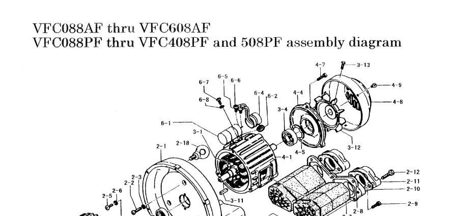
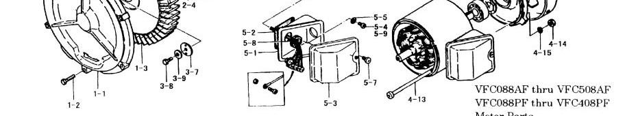
18 VFC088AF~VFC608AF, VFC088PF~VFC508PF 17
19 Guarantee Period and Scope of Guarantee <Product guarantee and scope of guarantee> The guarantee period of for product shall be 1 year after shipment to the specified destination. If any fault has occurred during the guarantee period in a proper use condition within he product specification range, the faulty part will be exchanged or repaired free of charge. However, if the fault corresponds to any of the following cases, it will be excluded from the scope of guarantee: 1)due to improper handling or use by the User 2)due to causes of fault other then of delivered product 3)due to improper repair of modification 4)due to natural calamity or disaster, which does not belong to the responsibility of supplier. The said guarantee means the guarantee for supplied product itself and we take no responsibility for the damage induced from the fault of the product. The guarantee is effective only in Japan. <Charged repair> The investigation and repair after the expiration of guarantee period will be charged. Even during the guarantee period, we accept the repair of fault and the cause investigation due to reasons out of the scope of guarantee for payment. 18
20 Head Office 230, Moriwake, Miyuki-cho, Fukuyama-city, Hiroshima, , Japan Tel Fax
RING BLOW VFZ-e Standard Model Series
 Instruction Manual RING BLOW VFZ-e Standard Model Series CAUTION Read the instruction manual carefully before you install, put into operation and maintain the Ring Blow and handle it properly. For the
 Instruction manual RING COMPRESSOR VFZ-7W(5W) Standard Model Series VFC805A-7(5)WS WARNING Read the instruction manual carefully before you install, put into operation and maintain the Ring Compressor
Centrifugal Fan Turbofan Type KT/KP
 Instruction Manual TF-113-01 Centrifugal Fan Turbofan Type KT/KP Do not carry out operation, inspection or maintenance of the fan until you read this manual and understand the content. Keep this manual
Installation/Instruction Manual
 1510876HC8902 Pressurized ventilators (for device cooling) Model Blade diameter (cm) Indoor or outdoor EF-20UYS-UL EF-25UAS-UL EF-30UBS-UL 20 25 30 Indoor Installation/Instruction Manual For customers
MD SERIES Instruction Manual
 IWAKI Magnetic Drive Pump MD SERIES Instruction Manual Read this manual before use of product Thank you for having selected the Iwaki Magnetic Drive Pump MD series. This manual deals with the correct handling
Original instructions. Operation Manual & Cautions
 Original instructions Operation Manual & Cautions Thank you for purchasing the Mistresa from Showa Denki. This manual explains the specifications for the [Mistresa units from CRN Series]. Please read the
Electric Blower Motor Operating Instructions and Warnings
 ZF-9503-4E Electric Blower Motor Operating Instructions and Warnings Centrifugal Motor Direct-coupling Blower Thank you for purchasing Showa Denki s blower. These Operating Instructions and Warnings provide
SELF-PRIMING JET PUMPS
 SS Anti-Rust SS Shaft Copper & Cold-rolled SELF-PRIMING JET PUMPS CONTENTS 1. Applications.... Model Description.... Technical Data... 4. Implementation Standards... 5. Safety Precautions... 6. Product
Pressure Switches Precautions 1 Be sure to read this before handling.
 Pressure Switches Precautions 1 Design / Selection 1. Confirm the specifications. Products represented in this catalog are designed ony for use in compressed air systems (including vacuum). Do not operate
Instruction Manual for Dust Collector
 YFAA11A-076ERe2 Instruction Manual for Dust Collector Dust Collector with Work Table Workrésa (WRM) Introduction Thank you for purchasing our Showa Denki s Dust Collector with Work Table (WRM) this time.
Panel Fan Series Operators Manual (Galvanized and Polymer)
") Panel Fan Series Operators Manual (Galvanized and Polymer) Galvanized Panel Fan with Three Wing Blade IMPORTANT: READ AND SAVE THESE INSTRUCTIONS Read all instructions carefully before attempting to assemble,
Panel Fan Series Operators Manual (Galvanized and Polymer) Galvanized Panel Fan with Three Wing Blade IMPORTANT: READ AND SAVE THESE INSTRUCTIONS Read all instructions carefully before attempting to assemble,
Handling or using the product improperly and in disregard of the instructions with this mark might result in serious bodily injury or death.
 Please Read: Safety Precautions DC AC In order to ensure that this product is used safely, be sure that you read and understand the following precautions fully and use the product only as directed. Be
INSTRUCTION- AND MAINTENANCE MANUAL FOR ELECTROMAGNETIC AIR PUMP JDK-60, JDK-80, JDK-100, JDK-120
 INSTRUCTION- AND MAINTENANCE MANUAL FOR ELECTROMAGNETIC AIR PUMP MODEL : JDK-60, JDK-80, JDK-100, JDK-120 - release 29.01.2014 - We thank you for purchasing our air pump. Prior to use, it is kindly requested
OPERATION AND MONTAGE MANUAL ROOF FANS
 NO RF/U/2017 (ENGLISH) (valid since 13.10.2017) ROOF FANS RF / RFV Venture Industries Sp. z o.o. is not responsible for any damage caused by improper use of the fan and reserves the right to modify this
569, 570, 571, 572 Series
 Please read and save this Repair Parts Manual. Read this manual and the General Operating Instructions carefully before attempting to assemble, install, operate or maintain the product described. Protect
HORIZONTAL MULTISTAGE CENTRIFUGAL PUMP
 HORIZONTAL MULTISTAGE CENTRIFUGAL PUMP WWPPCHLFT260 Instructions WWPPCHLFT260_Horizontal Multistage Centrifugal Pump_IB.indd 1 READ THIS MANUAL CAREFULL BEFORE INSTALL, START THE PUMP 1. Suction 2. Plug
569, 570, 571, 572 Series
 Please read and save this Repair Parts Manual. Read this manual and the General Operating Instructions carefully before attempting to assemble, install, operate or maintain the product described. Protect
Patterson/AMT Inline Circulator Pump Refer to pump manual for General Operating and Safety Instructions.
 Please read and save this Repair Parts Manual. Read this manual and the General Operating Instructions carefully before attempting to assemble, install, operate or maintain the product described. Protect
OPERATION AND MONTAGE MANUAL ROOF FANS
 NO RFEC/U/2017-1 (EN) (valid since 18.08.2017) ROOF FANS RF/EC...-... / RFV/EC...-... Venture Industries Sp. z o.o. is not responsible for any damage caused by improper use of the fan and reserves the
568X, 587X, 588X Series
 Please read and save this Repair Parts Manual. Read this manual and the General Operating Instructions carefully before attempting to assemble, install, operate or maintain the product described. Protect
SELF-PRIMING CENTRIFUGAL PUMPS BMLS-M & BMLS-H
 SELF-PRIMING CENTRIFUGAL PUMPS BMLS-M & BMLS-H INSTALLATION, OPERATION & MAINTENANCE INSTRUCTIONS HP Phase Medium Head High Head 3 1 BMLS 300 M BMLS 300 H 3 3 BMLS 300 M3 BMLS 300 H3 5 1 BMLS 500 M BMLS
Installation Instructions Part No , Part No Part No
 Torsion-Flex Motor mount for PSC motors and Rigid-Mount for ECM motors Replacement Kit Cancels: New Installation Instructions Part No. 327752-401, Part No. 327753-401 Part No. 327754-401 IIK-310A-45-11
Operation Manual R205BV, R209BV
 Operation Manual R205BV, R209BV 1 Safety Instruction The rotary evaporator is manufactured according to current methods and accepted safety regulations. However, risks still exist during the installation,
Panel Fan Series Operators Manual (Galvanized and Polymer)
") Panel Fan Series Operators Manual (Galvanized and Polymer) 52" Belt Drive, Galvanized Panel Fan with Three Wing Blade IMPORTANT: READ AND SAVE THESE INSTRUCTIONS Read all instructions carefully before
Panel Fan Series Operators Manual (Galvanized and Polymer) 52" Belt Drive, Galvanized Panel Fan with Three Wing Blade IMPORTANT: READ AND SAVE THESE INSTRUCTIONS Read all instructions carefully before
12 VELOCITY OWNER S MANUAL OPERATING INSTRUCTIONS - MAINTENANCE - SAFETY - TROUBLESHOOTING
 12 VELOCITY OWNER S MANUAL OPERATING INSTRUCTIONS - MAINTENANCE - SAFETY - TROUBLESHOOTING This manual contains very important safety warnings and information. Read and save these instructions for future
AZN ATEX INSTALLATION AND MAINTENANCE
 ZerAx AZN ATEX INSTALLATION AND MAINTENANCE 924714-0 English 924714-0 GB ZerAx axial flow fans type AZN ATEX Installation and maintenance 1. Application 2. Handling 2.1 Marking 2.2 Weight 2.3 Temperature
PBX series OPERATION MANUAL
 Submersible pump for pumping sandy water PBX series OPERATION MANUAL Thank you for purchasing a KOSHIN submersible pump. This instruction manual contains cautionary points for using the pump safely. Be
INSTALLATION, OPERATION & MAINTENANCE MANUAL
 CENTRAL FANS COLASIT LTD Unit 12A, Palmers Road, East Moons Moat, Redditch. Worcs. B98 0RF Tel: 01527-517200 Fax: 01527-517195 Edition 04_13 INSTALLATION, OPERATION & MAINTENANCE MANUAL CIV Fan Range Valid
LC Series - Light Commercial Pump Station Installation and Operation Manual
 LC Series - Light Commercial Pump Station Installation and Operation Manual Please keep this manual with the pump station Content Rain Bird LC Series Overview... Safety Instruction... Operation... 3 Pump
INSTALLATION, OPERATION, AND MAINTENANCE MANUAL
 INSTALLATION, OPERATION, AND MAINTENANCE MANUAL TUBE AXIAL FANS BTA, WTA, HTA, DDA The purpose of this manual is to aid in the proper installation and operation of the fans. These instructions are intended
Patterson/AMT Inline Circulator Pump Refer to pump manual for General Operating and Safety Instructions.
 Please read and save this Repair Parts Manual. Read this manual and the General Operating Instructions carefully before attempting to assemble, install, operate or maintain the product described. Protect
KRF15A-03 KRF25A-03 KRF40A-03
 OILLESS ROTARY VACUUM PUMP & BLOWER ORION DRY PUMP KRF15A-03 KRF25A-03 KRF40A-03 KRF40A-03 CAUTION This product is intended only for industrial use. Use with caution. Read this Instruction Manual and follow
INSTALLER: PLEASE LEAVE THIS MANUAL FOR THE OWNER S USE. Condensate Return Systems General Installation, Operation, & Service Instructions !
 Condensate Return Systems General Installation, Operation, & Service Instructions INSTALLER: PLEASE LEAVE THIS MANUAL FOR THE OWNER S USE. SAFETY INSTRUCTIONS This safety alert symbol will be used in this
VERTICAL GLANDLESS PUMP
 VERTICAL GLANDLESS PUMP INSTALLATION, OPERATION AND MAINTENANCE MANUAL INDEX Sl.No CONTENTS Page No. 1 Introduction 02 2 Unpacking 04 3 Installation procedure for VGP (Pump dispatched without motor) 07
Acquaer Ltd. H-4900, Fehérgyarmat, Szatmári út 11. CENTRIFUGAL PUMP Instruction Manual ACm60 / ACm75 / ACm150 / ACm150B2
 CENTRIFUGAL PUMP Instruction Manual ACm60 / ACm75 / ACm150 / ACm150B2 Congratulations on your purchase of a LEO Centrifugal Pump It is important that you read, fully understand and observe the following
STORAGE, ERECTION, OPERATION AND MAINTENANCE MANUAL FOR CENTRIFUGAL FANS MODEL - MXE
 ISO 9001 : 2000 STORAGE, ERECTION, OPERATION AND MAINTENANCE MANUAL FOR CENTRIFUGAL FANS MODEL - MXE CUSTOMER : 1 CONTENTS 1 SAFETY... 5 1.1 General... 6 1.2 Description of symbols and pictograms... 6
Spencer Vortex Regenerative Blowers. Installation, Operation and Maintenance Instructions. Important VB002 VB037XP VB055. Serial No: Model No:
 Spencer Vortex Regenerative Blowers Serial No: Model No: Installation, Operation and Maintenance Instructions VB002 VB037XP VB055 Important Read and become familiar with this manual prior to unpacking
CPE RANGE PUMPS CPE RANGE PUMPS. MODEL Nos: CPE15A1 15A3 20A1 20A3 30A1 30A3 PART Nos:
 CPE RANGE PUMPS CPE RANGE PUMPS MODEL Nos: CPE15A1 15A3 20A1 20A3 30A1 30A3 PART Nos: 7120305 7120310 7120315 7120320 7120325 7120330 OPERATION & MAINTENANCE INSTRUCTIONS GC0514 Contents Specifications...
Installation Instructions
 0908HN50 Lossnay Energy Recovery Ventilator Model: LGH-50RSDC-E (0-0V 50Hz) Installation Instructions (For use by dealer/contractor) Contents Safety precautions... Outline drawings... Standard installation
1 1/8 Inch Centrifugal Pump Operation and Maintenance Guide
 1 1/8 Inch Centrifugal Pump Operation and Maintenance Guide Installation Location! The pump should be located as close as possible to the liquid source so that the suction line can be as short and direct
MX Series (MX-70 & MX-100) Instruction Manual
 Instruction Manual") IWAI Magnetic Drive Pump MX Series (MX-70 & MX-100) Instruction Manual Read this manual before use of product Thank you for having selected the Iwaki Magnetic Drive Pump MX series. This manual deals with
IWAI Magnetic Drive Pump MX Series (MX-70 & MX-100) Instruction Manual Read this manual before use of product Thank you for having selected the Iwaki Magnetic Drive Pump MX series. This manual deals with
ISOLATED DIRECT DRIVE PLENUM FAN (IDDP)
") Our Expertise, Your Air-Moving Solution ISOLATED DIRECT DRIVE PLENUM FAN (IDDP) PART# 0601710001_rev_A INSTALLATION, OPERATION & MAINTENANCE MANUAL Please read and save these instructions for future reference.
Our Expertise, Your Air-Moving Solution ISOLATED DIRECT DRIVE PLENUM FAN (IDDP) PART# 0601710001_rev_A INSTALLATION, OPERATION & MAINTENANCE MANUAL Please read and save these instructions for future reference.
PANEL FAN SERIES OPERATORS MANUAL (Galvanized and Polymer)
") PANEL FAN SERIES OPERATORS MANUAL (Galvanized and Polymer) Galvanized Panel Fan IMPORTANT: READ AND SAVE THESE INSTRUCTIONS Read all instructions carefully before attempting to assemble, install, operate
PANEL FAN SERIES OPERATORS MANUAL (Galvanized and Polymer) Galvanized Panel Fan IMPORTANT: READ AND SAVE THESE INSTRUCTIONS Read all instructions carefully before attempting to assemble, install, operate
Operating Instructions
 Operating Instructions Varioset Standard After-sales service For after-sales service please contact the Veit representative in your country. GmbH & Co. Justus - von - Liebig - Str. 15 D - 86899 Landsberg
SWP. (Models SWP08 through SWP20) IMPORTANT! Read before proceeding! OPERATION & MAINTENANCE MANUAL
 IMPORTANT! Read before proceeding! OPERATION & MAINTENANCE MANUAL") SWP (Models SWP08 through SWP20) OPERATION & MAINTENANCE MANUAL IMPORTANT! Read before proceeding! Read carefully before attempting to assemble, install, operate or maintain the product described. Protect
SWP (Models SWP08 through SWP20) OPERATION & MAINTENANCE MANUAL IMPORTANT! Read before proceeding! Read carefully before attempting to assemble, install, operate or maintain the product described. Protect
Patterson/AMT Inline Circulator Pump Refer to pump manual for General Operating and Safety Instructions.
 Please read and save this Repair Parts Manual. Read this manual and the General Operating Instructions carefully before attempting to assemble, install, operate or maintain the product described. Protect
AXPR Wall Mounted Axial Panel Fans
 Bulletin 78-January-03-06 AXPR Wall Mounted Axial Panel Fans INSTALLATION, OPERATION, AND MAINTENANCE MANUAL This publication contains the installation, operation and maintenance instructions for the AXPR
Safety. Connect the product properly to the ground. (Malfunctioning or power leaks can cause electrical shock.)
") User s Manual TEVHR Contents Safety...1 Control List...2 Components...3 Dimensions...3 Installation...4 Technical Specification...5 Electrical Connection...6 Electrical Scheme...7 Maintenance...10 Control...11
User s Manual TEVHR Contents Safety...1 Control List...2 Components...3 Dimensions...3 Installation...4 Technical Specification...5 Electrical Connection...6 Electrical Scheme...7 Maintenance...10 Control...11
Tornado Operations & Maintenance Manual
 Tornado Industries, LLC 333 Charles Court West Chicago, IL 60185 www.tornadovac.com Tornado Operations & Maintenance Manual MODEL NO. 99414 Form No. L9740AB Tornado Industries, LLC. All rights reserved
TECHNICAL & SERVICE MANUAL WINDOW TYPE AIR CONDITIONER SA 123A FILE NO. SA 123A REFERENCE NO. SM700513
 TECHNICAL & SERVICE MANUAL SA 123A FILE NO. WINDOW TYPE AIR CONDITIONER Model No. Product Code No. Destination SA-123A 1 851 006 95 Australia SA 123A REFERENCE NO. SM700513 IMPORTANT! Please Read Before
ACN SMOKE INSTALLATION AND MAINTENANCE
 NovAx ACN SMOKE INSTALLATION AND MAINTENANCE 918149-0 English 918149-0 GB Installation and maintenance NovAx smoke exhaust fan type ACN smoke 1. Application 2. Handling 2.1 Marking 2.2 Weight 2.3 Transport
MNEFDD54 & MNBCDD54 GALVANIZED WALL FANS Installation, Operation, and Maintenance Instructions
 FARM PRODUCTS DIVISION MEMBER OF AMCA AMERICAN COOLAIR CORPORATION P.O. BOX 2300 JACKSONVILLE, FLORIDA 32203 PHONE (904) 389-3646 FAX (904) 387-3449 E-MAIL - fans@coolair.com MNEFDD54 & MNBCDD54 GALVANIZED
Installation and Maintenance Novax Smoke Exhaust Fan Type ACN Smoke
 918149-0 GB Installation and Maintenance Novax Smoke Exhaust Fan Type ACN Smoke 1. Application 2. Handling 2.1 Marking 2.2 Weight 2.3 Transport 3. Storage 4. Installation 4.1 Prior to attachment 4.2 Attachment
TYPE FSD KYOWA EXHAUST GAS SCRUBBER OPERATION MANUAL
 1 TYPE FSD KYOWA EXHAUST GAS SCRUBBER OPERATION MANUAL THAI KYOWA KAKO CO.,LTD. WWW.KYOWA.CO.TH 2 CONTENTS 1.SPECIFICATIONS... 2 2.EXTERNAL VIEW.. 3 3.FUNCTION OF EACH SECTION 4 4.SAFETY CONTROL AND SAFETY
KQ Series. Multistage Booster Pump System. Installation Manual. ISO 9001 Certified KQ200/400 KQ800
 KQ Series Multistage Booster Pump System Installation Manual KQ200/400 KQ800 ISO 9001 Certified Description The KQ series booster pump is an all-in-one compact and reliable automatic multistage centrifugal
AVANI Grinding Booth
 AVANI Grinding Booth GB-6066-DD Customer: Kelly Walsh Customer PO#: 11305 AVANI SO#: Serial #: 153920-153921 Ship Date / Install Date: Tested By: Please read and save these instructions. Read carefully
Washing Machine OWNER S MANUAL TRWTL-70. Before using your washing machine, please read this manual carefully and keep it for future reference.
 Before using your washing machine, please read this manual carefully and keep it for future reference. Washing Machine OWNER S MANUAL TRWTL-70 Read This Manual Inside you will find many helpful hints on
TECHNICAL & SERVICE MANUAL WINDOW TYPE AIR CONDITIONER SA 183A FILE NO. SA 183A REFERENCE NO. SM Destination Australia SA-183A
 TECHNICAL & SERVICE MANUAL SA 183A FILE NO. WINDOW TYPE AIR CONDITIONER Model No. Product Code No. SA-183A 1 851 006 96 Destination Australia SA 183A REFERENCE NO. SM700514 IMPORTANT! Please Read Before
Series 1140 and 1141 Temperature Regulators
 Hoffman Specialty Installation & Maintenance Instructions HS-504(E) Series 1140 and 1141 Temperature Regulators! CAUTION FOLLOW ALL INSTALLATION AND OPERATING INSTRUCTIONS. TURN OFF WATER OR STEAM BEFORE
SERVICE MANUAL. 300 Series Motorized 35650, 35651, 35652, 36750, 36751, and Model
 Section: MOYNO 500 PUMPS Page: 1 of 4 Date: March 1, 1998 SERVICE MANUAL MOYNO 500 PUMPS 300 Series Motorized 35650, 35651, 35652, 36750, 36751, and 36752 Model DESIGN FEATURES Housing: Cast iron/316 SS
ENERVEX GSV GREASE FAN
 ENERVEX GSV 200-450 GREASE FAN 3001391 12.16 Installation & Operating Manual READ AND SAVE THESE INSTRUCTIONS! ENERVEX Inc. 1685 Bluegrass Lakes Parkway Alpharetta, GA 30004 USA P: 770.587.3238 F: 770.587.4731
Installation Instructions
 40MBFQ Floor Console Ductless System Sizes 09 to 58 Installation Instructions TABLE OF CONTENTS PAGE SAFETY CONSIDERATIONS... 2 PARTS LIST... 3 SYSTEM REQUIREMENTS... 4 WIRING... 4 DIMENSIONS... 5 CLEARANCES...
General safety precautions English
 English A min (m 2 ) 550 530 540 510 520 490 500 470 480 450 460 430 440 410 420 390 400 370 380 350 360 330 340 310 320 290 300 270 280 250 260 230 240 210 220 190 200 170 180 150 160 130 140 110 120
General safety precautions English
 English A min (m 2 ) 550 530 540 510 520 490 500 470 480 450 460 430 440 410 420 390 400 370 380 350 360 330 340 310 320 290 300 270 280 250 260 230 240 210 220 190 200 170 180 150 160 130 140 110 120
INTRODUCTION. NOTE: Read the entire instruction manual before starting the installation. FIRE, EXPLOSION, ELECTRICAL SHOCK HAZARD
 Installation Instructions NOTE: Read the entire instruction manual before starting the installation. SAFETY CONSIDERATIONS Improper installation, adjustment, alteration, service, maintenance, or use can
Service Manual Washing Machine
 Http://global.midea.com.cn Service Manual Washing Machine Note: Before serving the unit,please read this at first, Always contact wih your service center if meet problem. TABLE OF CONTENTS 1. SAFETY PRECAUTION...
BESF Box Ventilator. Installation & Operating Manual USA CAN READ AND SAVE THESE INSTRUCTIONS
 Installation & Operating Manual 3001806 03.02 USA CAN BESF Box Ventilator READ AND SAVE THESE INSTRUCTIONS 1200 Northmeadow Parkway, STE 180 Roswell, GA 30076 (770) 587-3238 (800) 255-2923 Fax (770) 587-4731
Installation of Glass Lined Equipment
 Installation of Glass Lined Equipment Information given herein is for guidance only and may not be complete. It is important that only trained and competent personnel are permitted to handle glass lined
OWNERS GUIDE TO INSTALLATION AND OPERATION
 OWNERS GUIDE TO INSTALLATION AND OPERATION SPM SERIES HIGH POWER CENTRIFUGALS READ THESE INSTRUCTIONS CAREFULLY Read these installation instructions in detail before installing your pump. Be sure to check
SERIES 'HE' PLASTIC HORIZONTAL PUMP MODEL: H2 x1½
 SERIES 'HE' PLASTIC HORIZONTAL PUMP MODEL: H2 x1½ OPERATION AND SERVICE GUIDE O-820_R FEBRUARY 2013 Refer to Bulletin P-201 and Parts Lists: P-7200, P-7250. SAFETY PRECAUTIONS BEFORE STARTING PUMP 1. Read
BESF Box Ventilator USA CAN. Product Information. Mechanical Installation. ... Chapter 3. Electrical Installation. ... Chapter 4
 Installation & Operating Manual BESF Box Ventilator USA CAN Product Information... Chapter 1 + 2 Mechanical Installation... Chapter 3 Electrical Installation... Chapter 4 Start Up and Configuration...
CONTENTS DESCRIPTION UNPACKING DIMENSIONS
 INSTALLATION INSTRUCTIONS Ventilating Fan ModelNo.FV-08VRE CONTENTS GENERAL SAFETY INFORMATION DESCRIPTION UNPACKING SUPPLIED ACCESSORIES DIMENSIONS WIRING DIAGRAM INSTALLATION (BETWEEN JOISTS MOUNTING)
FSW300 Series Flow Switch
 . FSW300 Series Flow Switch - 2 - Series FSW300 Series FSW300 Table of contents page 0 About this operating manual... 4 1 Device description... 5 1.1 Intended use... 5 1.1.1 Reed contact - Switching of
6. COOLING SYSTEM 6-0 COOLING SYSTEM MXU 500
 6 COOLING SYSTEM SYSTEM FLOW PATTERN----------------------------------------------- 6-1 SERVICE INFORMATION------------------------------------------------ 6-2 TROUBLESHOOTING-----------------------------------------------------
AOYG18LFC OUTDOOR UNIT INSTALLATION MANUAL INSTALLATION MANUAL. For authorized service personnel only. PART NO
 AOYG8LFC OUTDOOR UNIT INSTALLATION MANUAL INSTALLATION MANUAL For authorized service personnel only. English PART NO. 93778639 93778639_IM.indb /20/20 6:07:25 PM AIR CONDITIONER OUTDOOR UNIT INSTALLATION
TH450A-CRB TH550A-CRB THP550-CRB/TS3000
 TH450A-CRB TH550A-CRB THP550-CRB/TS3000 INSTRUCTION MANUAL CLEAN TYPE INDUSTRIAL ROBOT SPECIFICATIONS Notice Make sure that this instruction manual is delivered to the final user of Toshiba Machine s industrial
HT650 TM FAN DRIVE SERVICE INSTRUCTIONS
 HT650 TM FAN DRIVE SERVICE INSTRUCTIONS When unpacking your product, remove all components and inspect them to ensure that no damage occurred during shipping. If any components are missing or damaged,
WATLOW IND. WATROD Modular Duct Heater Installation & Maintenance Manual I&M NUMBER: Page: 1 Date:6/11/2008 Rev: 2
 I&M NUMBER: 316-42-15-1 Page: 1 _ Pre Installation Check to make sure that heater received is the same as that ordered. Elements may come in contact with each other during shipment. Minor adjustments to
"S" SERIES IMMERSIBLE PUMP OWNER'S MANUAL INSTALLATION OPERATION PARTS Models S12 S16
 Webster Pumps "S" SERIES IMMERSIBLE PUMP OWNER'S MANUAL INSTALLATION OPERATION PARTS Models S12 S16 PLEASE READ THE FOLLOWING INFORMATION PRIOR TO INSTALLING AND USING Webster PUMPS or HAYWARD VALVES,
INSTRUCTION MANUAL. Keep this manual in a safe place for future reference TEMPERATURE CONTROL STEAM TRAP LEX3N-TZ LEX3N-TZ.
 INSTRUCTION MANUAL Keep this manual in a safe place for future reference TEMPERATURE CONTROL STEAM TRAP LEX3N-TZ LEX3N-TZ Manufacturer 881 Nagasuna, Noguchi, Kakogawa, Hyogo 675-8511, Japan Tel: [81]-(0)79-422-1122
CORONA BURNER CONTROLLER INSTRUCTION MANUAL RCF15 EXCLUSIVE FOR FLAME ROD. Corona Corporation
 CORONA BURNER CONTROLLER INSTRUCTION MANUAL RCF15 EXCLUSIVE FOR FLAME ROD Corona Corporation This instruction manual contains important information for safe use of this device. Keep this instruction manual
Installer manual AG-AA10. Air/air heat pump IHB GB AG-AA10-30 AG-AA10-40/50
 -30 Installer manual Air/air heat pump -40/50 IHB GB 1516-1 331554 Table of Contents 1 Important information 2 5 Installation 7 Safety information 2 Model combinations 7 Read before starting the installation
REF. NO Clamp Assembly 8 1 set Gasket (4 per set) S.S. Lock-washer 3/8 x 1/ Brass Impeller 3.
 S.S. Lock-washer 3/8 x 1/ Brass Impeller 3.") 4.4 SUPPLY PUMPAK ASSEMBLY NOTE: This section applies only to systems, which include a supply pumpak. Only the H6, XA, and XC series systems contain a supply pumpak. If your system is a single zone, H6
4.4 SUPPLY PUMPAK ASSEMBLY NOTE: This section applies only to systems, which include a supply pumpak. Only the H6, XA, and XC series systems contain a supply pumpak. If your system is a single zone, H6
CS 2. Central Station Air Handlers Double Wall & Single Wall Installation, Operation & Maintenance Manual. Form No. 6120A
 CS 2 Central Station Air Handlers Double Wall & Single Wall Installation, Operation & Maintenance Manual Form No. 6120A TABLE OF CONTENTS Page Inspection... 2 Shipment of Units... 2 Handling... 2 Installation...
CR-1730R User s Manual
 CappRondo Refrigerated Centrifuge CR-1730R User s Manual AHN Biotechnologie GmbH Uthleber Weg 14 99734 Nordhausen Germany www.capp.dk info@capp.dk Tel. +49(0)3631 65242-0 Fax +49(0)3631 65242-90 DOC. No.:
TECHNICAL & SERVICE MANUAL WINDOW TYPE AIR CONDITIONER SA 128S5 FILE NO. SA 128S5 REFERENCE NO. SM700338
 TECHNICAL & SERVICE MANUAL SA 128S5 FILE NO. WINDOW TYPE AIR CONDITIONER Model No. Product Code No. Destination SA-128S5-A 1 851 004 09 General (50Hz) & Europe SA 128S5 REFERENCE NO. SM700338 IMPORTANT!
13-1. Temperature Regulator
 -1 Step 0 Type/Structure/Features Please refer to this for type, structure and features of. Step 1 Selection Please look at the ID chart to choose the right products depending on the intended uses. Details
This label warns for risk of electrical shock when failing to observe.
 MANUAL horizontal centrifugal pumps MB series ic drive SB series mechanical seal 1. Introduction 2. Safety precautions 3. Receipt 4. Installation / Operation and Maintenance 4.1 Installation 4.2 Operation
Operating instructions
 ebm-papst Mulfingen GmbH & Co. KG Bachmühle D-74673 Mulfingen Phone +49 (0) 793-0 Fax +49 (0) 793-0 info@de.ebmpapst.com www.ebmpapst.com CONTENTS. SAFETY REGULATIONS AND NOTES. Levels of hazard warnings.
hp Dust Collector With Vacuum Attachment
 Please dispose of packaging for the product in a responsible manner. It is suitable for recycling. Help to protect the environment, take the packaging to the local amenity tip and place into the appropriate
Installation, Operation and Maintenance LOK-FLANGE Multitube Heat Exchangers
 Bulletin 1200/4 (Revised 5/12) Installation, Operation and Maintenance LOK-FLANGE Multitube Heat Exchangers INNOVATORS IN HEAT TRANSFER I. INSTALLATION OF HEAT EXCHANGERS A. HEAT EXCHANGER SETTINGS 1)
IEC- Direct-driven radial fans with IEC-Standardmotor
 EHND / ERND / ERNE / Contents. / Page 1. / Safety... 2 2. / Description... 4 3. / Condition of use... 4 4., / Storage, Transport... 5 5. / installation... 6 6. / operation... 8 7. / maintenance... 9 8.
ASL T6 / T7 / T8 / T9 FLOOR GRINDING MACHINES MANUAL
 ASL T6 / T7 / T8 / T9 FLOOR GRINDING MACHINES MANUAL 1 Contents Preface 3 1.1 Safety Guide 4 1.2 Precautions 4 Chapter II 5 Purchase Check, Technical Parameter and Product Description 5 2.1 Purchase Check
INSTRUCTION MANUAL DN0136 REVISION D
 INSTRUCTION MANUAL DN0136 REVISION D PIPING (Returns) Gravity return lines from system must be properly pitched down to unit inlet. Returns must also be trapped to prevent steam entry into the unit. An
USER S MANUAL ATH WH220
 USER S MANUAL ATH WH220 INDEX INTRODUCTION... - 3 - General information s... - 3 - Description of pneumatic jack... - 4 - Operation of jack... - 5 - Technical data... - 6 - Dimension drawing... - 6 - INSTALLATION...
CAR-MON DUST COLLECTORS SERIES 207, 2410, 3015
 INSTALLATION-OPERATION-MAINTENANCE CAR-MON DUST COLLECTORS SERIES 207, 2410, 3015 TEFC 3 phase motor Outlet duct Fan wheel housing Inlet duct connection After filter transition Optional after filter unit
Service Manual This Service Manual is written for the after sail service department, especially for the fix and maintenance workers.
 Service Manual This Service Manual is written for the after sail service department, especially for the fix and maintenance workers. Energy Recovery Ventilator (sold in Europe market) Model No. Panasonic
Enviro KES INSTALLATON MANUAL
 Enviro KES INSTALLATON MANUAL Spring Air Systems Inc., Oakville, Ontario Phone (905) 338-2999, Fax (905) 338-0179, info@springairsystems.com www.springairsystems.com KES Installation Manual. This publication
Installation Instructions
 Installation Instructions Cased Horizontal Furnace Coil CK3B A96318 Fig. 1 Model CK3B Furnace Coil NOTE: Read the entire instruction manual before starting the installation. SAFETY CONSIDERATIONS Improper
SERVICE MANUAL VC3ED FULL SIZE ELECTRIC CONVECTION OVEN - NOTICE -
 SERVICE MANUAL VC3ED FULL SIZE ELECTRIC CONVECTION OVEN VC3ED ML-137013 - NOTICE - This Manual is prepared for the use of trained Vulcan Service Technicians and should not be used by those not properly