Service Manual CAUTION ! WARNING SAFETY CONSIDERATIONS INTRODUCTION
|
|
|
- Leona Blake
- 6 years ago
- Views:
Transcription

1 38MGQ / 40MAQ/40MBC/40MBD/40MBF 538TR / 619PB/619RC/619RD/619RF Multi---Zone Ductless plit ystem izes 18 to 48 TABLE OF CONTENT PAGE AFETY CONIDERATION... 1 INTRODUCTION... 1 MODEL NUMBER NOMENCLATURE... 2 TANDARD FEATURE AND ACCEORIE... 4 COMBINATION TABLE... 5 PHYICAL DATA - OUTDOOOR... 6 DIMENION - OUTDOOR... 7 CLEARANCE - OUTDOOR ELECTRICAL DATA CONNECTION DIAGRAM WIRING DIAGRAM REFRIGERATION CYCLE DIAGRAM REFRIGERANT LINE YTEM EVACUATION AND CHARGING TROUBLEHOOTING APPENDIX AFETY CONIDERATION Installing, starting up, and servicing air-conditioning equipment can be hazardous due to system pressures, electrical components, and equipment location (roofs, elevated structures, etc.). Only trained, qualified installers and service mechanics should install, start -up, and service this equipment. Untrained personnel can perform basic maintenance functions such as cleaning coils. All other operations should be performed by trained service personnel. When working on the equipment, observe precautions in the literature and on tags, stickers, and labels attached to the equipment. Follow all safety codes. Wear safety glasses and work gloves. Keep quenching cloth and fire extinguisher nearby when brazing. Use care in handling, rigging, and setting bulky equipment. Read this manual thoroughly and follow all warnings or cautions included in literature and attached to the unit. Consult local building codes and National Electrical Code (NEC) for special requirements. Recognize safety information. This is the safety -alert symbol!!. When you see this symbol on the unit and in instructions or manuals, be alert to the potential for personal injury. Understand these signal words: DANGER, WARNING, and CAUTION. ervice Manual These words are used with the safety -alert symbol. DANGER identifies the most serious hazards which will result in severe personal injury or death. WARNING signifies hazards which could result in personal injury or death. CAUTION is used to identify unsafe practices which may result in minor personal injury or product and property damage. NOTE is used to highlight suggestionswhich will result in enhanced installation, reliability, or operation.! WARNING ELECTRICAL HOCK HAZARD Failure to follow this warning could result in personal injury or death. Before installing, modifying, or servicing system, main electrical disconnect switch must be in the OFF position. There may be more than 1 disconnect switch. Lock out and tag switch with a suitable warning label.!! WARNING EXPLOION HAZARD Failure to follow this warning could result in death, serious personal injury, and/or property damage. Never use air or gases containing oxygen for leak testing or operating refrigerant compressors. Pressurized mixtures of air or gases containing oxygen can lead to an explosion. CAUTION EQUIPMENT DAMAGE HAZARD Failure to follow this caution may result in equipment damage or improper operation. Do not bury more than 36 in. (914 mm) of refrigerant pipe in the ground. If any section of pipe is buried, there must be a 6 in. (152 mm) vertical rise to the valve connections on the outdoor units. If more than the recommended length is buried, refrigerant may migrate to the cooler buried section during extended periods of system shutdown. This causes refrigerant slugging and could possibly damage the compressor at start -up. INTRODUCTION This ervice Manual provides the necessary information to service, repair, and maintain the multi-zone family of heat pumps. ection 2 of this manual has an appendix with data required to perform troubleshooting. Use the Table of Contents to locate a desired topic.
2 MODEL NUMBER NOMENCLATURE INDOOR UNIT 40 MB Q B 09 D = FAN COIL UNIT MA =HIGHWALL MB = CAETTE, DUCTED, FLOOR CONOLE VOLTAGE 3 = 208/ YTEM TYPE Q =HEATPUMP NOT UED B=ALL NOMINAL CAPACITY /4 TON TON /2 TON TON INDOOR FAN COIL TYPE B =HIGHWALL C =CAETTE D =DUCTED F = FLOOR CONOLE OUTDOOR UNIT 38 MG Q C = OUTDOOR UNIT MG =ALL VOLTAGE 3 = 208/ YTEM TYPE Q =HEATPUMP MAXIMUM NUMBER OF FAN COIL UNIT THAT CAN BE CONNECTED TO THE OUTDOOR UNIT C =1:2 D =1:3 F =1:4OR1:5 NOMINAL CAPACITY /2 TON /4 TON TON TON NOT UED UNIT TYPE --- = OUTDOOR UNIT V Week of Manufacture equential erial Number Year of Manufacture V=ALLMODEL Use of the AHRI Certified TM Mark indicates a manufacturer s participation in the program For verification of certification for individual products, go to 2

3 INDOOR UNIT 619 P E Q 009 B B M A 619 = FAN COIL UNIT A = ALL MODEL P=HIGHWALL R = CAETTE, DUCTED, FLOOR CONOLE VOLTAGE E = /I/60 M=ALL YTEM TYPE Q =HEATPUMP B=ALL NOMINAL CAPACITY /4TON TON /2TON TON INDOOR FAN COIL TYPE B= High Wall C = Cassette D=Ducted F = Floor Console OUTDOOR UNIT 538 T E Q 018 R C M A 538 = Air --- Cooled Condenser A = ALL MODEL T =MODEL VOLTAGE E = /I/60 YTEM TYPE Q =HEATPUMP M =ALL MAXIMUM NUMBER OF FAN COIL UNIT THAT CAN BE CONNECTED TO THE OUTDOOR UNIT C=1:2 D=1:3 F=1:4OR1:5 NOMINAL CAPACITY /2TON /4TON TON TON UNIT TYPE R = OUTDOOR UNIT Use of the AHRI Certified TM Mark indicates a manufacturer s participation in the program For verification of certification for individual products, go to 3
4 TANDARD FEATURE AND ACCEORIE Ease of Installation INDOOR UNIT Mounting Bracket Low Voltage Controls Comfort Features Microprocessor Control Wired Remote Control for High Walls, Cassette and Floor Console A Wired Remote Control for Ducted Wireless Remote Control Rapid Cooling and Heating Automatic Air weep Cold Blow Prevention Continuous Fan Auto Restart Function Auto Changeover Follow Me Energy aving Features Inverter Driven Compressor leep Mode 24 Hour top/tart Timer 46 F Heating Mode (Heating etback) afety And Reliability Indoor Coil Freeze Protection 3MinuteTimeDelayForCompressor High Compressor Discharge Temperature Low Voltage Protection Compressor Overload Protection Compressor Over Current Protection IPM Module Protection Ease of ervice Cleanable Filters Diagnostic Error Messages Displayed On Front Panel Application Flexibility Condensate Pumps For High Walls and Floor Console Condensate Pump For Cassette and Ducted Crankcase Heater Basepan Heater Legend tandard A Accessory A Fig. 1 Condensate Pump Accessory On high wall fan coils, the condensate pump has a lift capability of 12 ft. (3.6 m) on the discharge side with the pump mounted in the fan coil or 6 ft (1.8 m) on the suction side if the pump is remote mounted. The pump is recommended when adequate drain line pitch cannot be provided, or when the condensate must move up to exit. OUTDOOR UNIT Crankcase Heater tandard on all unit sizes. Heater clamps around compressor oil stump. 4
5 COMBINATION TABLE Table 1 Combinations Table ize 18 Indoor Unit minal Unit Btuh Indoor Model Number Indoor Model Number High Wall Cassette Ducted Floor Console 9,000 40MAQB09B PEQ009BBMA 12,000 40MAQB12B PEQ012BBMA 9,000 40MBQB09C REQ009CBMA 12,000 40MBQB12C REQ012CBMA 9,000 40MBQB09D REQ009DBMA 12,000 40MBQB12D REQ012DBMA 9,000 40MBQB09F REQ009FBMA 12,000 40MBQB12F REQ012FBMA Table 2 Combinations Table ize 27 Indoor Unit minal Unit Btuh Indoor Model Number Indoor Model Number High Wall Cassette Ducted Floor Console 9,000 40MAQB09B PEQ009BBMA 12,000 40MAQB12B PEQ012BBMA 18,000 40MAQB18B PEQ018BBMA 9,000 40MBQB09C REQ009CBMA 12,000 40MBQB12C REQ012CBMA 18,000 40MBQB18C REQ018CBMA 9,000 40MBQB09D REQ009DBMA 12,000 40MBQB12D REQ012DBMA 18,000 40MBQB18D REQ018DBMA 9,000 40MBQB09F REQ009FBMA 12,000 40MBQB12F REQ012FBMA Table 3 Combinations Table ize 36 and 48 Indoor Unit minal Unit Btuh Indoor Model Number Indoor Model Number High Wall Cassette Ducted Floor Console 9,000 40MAQB09B PEQ009BBMA 12,000 40MAQB12B PEQ012BBMA 18,000 40MAQB18B PEQ018BBMA 24,000 40MAQB24B PEQ024BBMA 9,000 40MBQB09C REQ009CBMA 12,000 40MBQB12C REQ012CBMA 18,000 40MBQB18C REQ018CBMA 9,000 40MBQB09D REQ009DBMA 12,000 40MBQB12D REQ012DBMA 18,000 40MBQB18D REQ018DBMA 24,000 40MBQB24D REQ024DBMA 9,000 40MBQB09F REQ009FBMA 12,000 40MBQB12F REQ012FBMA Outdoor Model Number 38MGQC Outdoor Model Number 38MGQD Outdoor Model Number 38MGQF MGQF Outdoor Model Number 538TEQ018RCMA Outdoor Model Number 538TEQ027RDMA Outdoor Model Number 538TEQ036RFMA 538TEQ048RFMA 5
6 PHYICAL DATA - OUTDOOR ystem Performance n -Ducted Performance Combination Ducted and n -Ducted Performance Ducted Operating Range Piping Electrical Outdoor Table 4 Outdoor ize Outdoor Model 3 8 MGQC MGQD MGQF MGQF TEQ018RCMA 538TEQ027RDMA 538TEQ036RFMA 538TEQ048RFMA Max Number of Zones Energy tar YE YE NO YE Cooling Rated Capacity Btu/h 18,000 25,000 36,000 42,000 Cooling Cap. Range Min - Max Btu/h 8,500~20,000 9,000~30,000 9,500~37,000 10,000~50,000 EER EER Heating Rated Capacity Btu/h 18,500 32,000 36,000 49,000 Heating Cap. Range Min - Max Btu/h 9,000~22,000 9,500~32,000 10,000~39,000 10,500~55,000 HPF Cooling Rated Capacity Btu/h 17,500 26,000 35,000 42,000 Cooling Cap. Range Min - Max Btu/h 8,500~20,000 9,000~30,000 9,500~36,500 10,000~50,000 EER EER Heating Rated Capacity Btu/h 18,250 32,000 36,000 50,000 Heating Cap. Range Min - Max Btu/h 9,000~22,000 9,500~32,000 10,000~39,000 10,500~55,000 HPF Cooling Rated Capacity Btu/h 17,000 27,000 34,000 42,000 Cooling Cap. Range Min - Max Btu/h 8,500~20,000 9,000~30,000 9,500~36, ~50000 EER EER Heating Rated Capacity Btu/h 18,000 32,000 36,000 51,000 Heating Cap. Range Min - Max Btu/h 9000~ ~ ,000~39,000 10,500~55,000 HPF Cooling Outdoor DB Min - Max F 4~122 4~122 4~122 4~122 Heating Outdoor DB Min - Max F 4~86 4~86 4~86 4~86 Total Piping Length Ft Piping to furthest FCU Ft Drop (OD above ID) Ft Lift (OD below ID) Ft Pipe Connection ize - Liquid In. 1/4*2 1/4*3 1/4*4 1/4*5 Pipe Connection ize - uction In. 3/8*2 3/8*3 1/2+3/8*3 1/2*2+3/8*3 Voltage, Phase, Cycle V/Ph/Hz 208/ / / / Power upply Indoor unit powered from outdoor unit MCA A MOCP - Fuse Rating A Unit Width In Unit Height In Unit Depth In Net Weight Lbs Airflow CFM 1,390 2,130 2,130 3,500 ound Pressure db(a)
 Depth in (mm) 12.60(320) 15.55(395) 15.55(395) 15.43(392) Weight - Net lbs (kg) 114.63(52) 154.76(70.2) 169.75(77) 255.50(115.9) Fig.")
7 DIMENION - OUTDOOR Table 5 Outdoor Unit ize Height in (mm) 27.56(700) 31.89(810) 31.89(810) 36.93(1369) Width in (mm) 33.27(845) 37.20(945) 37.20(945) 53.9(938) Depth in (mm) 12.60(320) 15.55(395) 15.55(395) 15.43(392) Weight - Net lbs (kg) (52) (70.2) (77) (115.9) Fig. 2 Outdoor Dimensions ize 18 7

8 DIMENION - OUTDOOR (CONTINUED) Fig. 3 Outdoor Dimensions ize 27 8

9 DIMENION - OUTDOOR (CONTINUED) Fig. 4 Outdoor Dimensions ize 36 9

10 DIMENION - OUTDOOR (CONTINUED) Fig. 5 Outdoor Dimensions ize 48 10
11 CLEARANCE - OUTDOOR A Air-inlet E D B C Air-outlet Fig. 6 Outdoor Unit Clearance Table 6 Outdoor Minimum Value UNIT in. (mm) A 24 (609) B 24 (609) C 24 (609) D 4 (101) E 4 (101) 11
12 ELECTRICAL DATA Table 7 High Wall UNIT IZE ystem Voltage OPERATING VOLTAGE INDOOR FAN VOLT/PHAE/HZ MAX / MIN V-PH-HZ FLA HP W /1/ / /1/ Table 8 Ducted UNIT IZE ystem Voltage OPERATING VOLTAGE INDOOR FAN VOLT/PHAE/HZ MAX / MIN FLA HP W /1/ / Table 9 Cassette Cassette UNIT IZE ystem Voltage OPERATING VOLTAGE INDOOR FAN VOLT/PHAE/HZ MAX / MIN V-PH-HZ FLA HP W /1/ / /1/ Table 10 Floor Console ystem Voltage OPERATING VOLTAGE INDOOR FAN UNIT IZE VOLT/PHAE/HZ MAX / MIN V-PH-HZ FLA HP W /1/ / /1/ Table 11 Multi Zone Outdoor Unit MAX UNIT IZE ystem Voltage OPERATING VOLTAGE COMPREOR OUTDOOR FAN MCA FUE/CB AMP VOLT/PHAE/HZ MAX / MIN RLA FLA HP W /1/ / *Permissible limits of the voltage range at which the unit will operate satisfactorily. LEGEND FLA - Fu ll Lo ad Am p s MCA - Minimum Circuit Amps RLA -RatedLoadAmps 12
13 WIRING All wires must be sized per NEC (National Electrical Code) or CEC (Canadian Electrical Code) and local codes. Use Electrical Data table MCA (minimum circuit amps) and MOCP (maximum over current protection) to correctly size the wires and the disconnect fuse or breakers respectively. Per caution note, only copper conductors with a minimum 300 volt rating and 2/64 -inch thick insulation must be used. The use of BX cable is not recommended. Recommended Connection Method for Power and Communication Wiring - Power and Communication Wiring: The main power is supplied to the outdoor unit. The field supplied 14/3 power/communication wiring from the outdoor unit to indoor unit consists of four (4) wires and provides the power for the indoor unit. Two wires are high voltage AC power, one is communication wiring and the other is a ground wire. Recommended Connection Method for Power and Communication Wiring (To minimize communication wiring interference) Power Wiring: The main power is supplied to the outdoor unit. The field supplied power wiring from the outdoor unit to indoor unit consists of three (3) wires and provides the power for the indoor unit. Two wires are high voltage AC power and one is a ground wire. To minimize voltage drop, the factory recommended wire size is 14/2 stranded with a ground. Communication Wiring: A separate shielded copper conductor only, with a minimum 300 volt rating and 2/64 -inch thick insulation, must be used as the communication wire from the outdoor unit to the indoor unit. Please use a separate shielded 16GA stranded control wire.! CAUTION EQUIPMENT DAMAGE HAZARD Failure to follow this caution may result in equipment damage or improper operation. Wires should be sized based on NEC and local codes. Use copper conductors only with a minimum 300 volt rating and 2/64 inch thick insulation.! CAUTION EQUIPMENT DAMAGE HAZARD Failure to follow this caution may result in equipment damage or improper operation. Be sure to comply with local codes while running wire from indoor unit to outdoor unit. Every wire must be connected firmly. Loose wiring may cause terminal to overheat or result in unit malfunction. A fire hazard may also exist. Therefore, be sure all wiring is tightly connected. wire should be allowed to touch refrigerant tubing compressor or any moving parts. Disconnecting means must be provided and shall be located within sight and readily accessible from the air conditioner. Connecting cable with conduit shall be routed through hole in the conduit panel. 13


14 CONNECTION DIAGRAM Fig. 7 Connection Diagram ize 18 Fig. 8 Connection Diagram ize 27 14


15 CONNECTION DIAGRAM CONTINUED Fig. 9 Connection Diagram ize 36 Fig. 10 Connection Diagram ize 48 tes: 1. Do not use thermostat wire for any connection between indoor and outdoor units. 2. All connections between indoor and outdoor units must be as shown. The connections are sensitive to polarity and will result in a fault code. 15
16 Fig. 11 PCB Board ize 18 16

17 Fig. 12 IPM Board ize 18 17
18 Fig. 13 PCB Board ize 27 18

19 Fig. 14 IPM Board ize 27 19
20 &RQQHFW WR WKH,QGRRU HYD LH RXW WHP VHQVRU 7 % $ǃ7 % %ǃ7 % &ǃ7 % 'ǃ7 % ( H[WHUQDO GULYH '& IDQ PRWRU FRQQHFWRU FRQQHFW WR H[KDXVW WHP VHQVRU &1 &1 &211(&7 72 $& )$ /2: 63((' &1 &1 $& IDQ PRWRU ORZ VHHG FRQQHFWRU &1 &1 $9 IDQ PRWRU 1 KDVH &1 &1 &1 &1 $& IDQ PRWRU FDDFLWRU FRQQHFWRU (OHFWULF ([DQVLRQ (OHFWULF ([DQVLRQ (OHFWULF ([DQVLRQ (OHFWULF ([DQVLRQ 9DOXH 9DOXH 9DOXH 9DOXH (OHFWULF ([DQVLRQ 9DOXH FRPPXQLFDWLRQ WHVW3RUW FRQQHFW WR GHWHFWRU H[WHUQDO GULYH '& IDQ H[WHUQDO GULYH '& IDQ PRWRU RXXW WHUPLQDO PRWRU LQXW WHUPLQDO FXUUHQW ORR FRPPXQLFDWLRQ $ FXUUHQW ORR FRPPXQLFDWLRQ % FXUUHQW ORR FRPPXQLFDWLRQ & FXUUHQW ORR FRPPXQLFDWLRQ & &1 / &1 1 FXUUHQW ORR FRPPXQLFDWLRQ ' &1 / &1 1 +HDWHU &1 / &1 1 +HDWHU FXUUHQW ORR FRPPXQLFDWLRQ ( )XVH $ 9 FRQQHFW WR WUP VHQVRU FRQQHFW WR HDUWK KLJK UHVVXUH VHQVRU FRQQHFW WR KLJK DQG ORZ UHVVXUH VHQVRU ORZ UHVVXUH VHQVRU )XVH 7 $ 9 WHVW UHRUW FRQQHFW WR GHWHFWRU GLJLWDO GLVOD\ EXWWRQ GLJLWDO GLVOD\ UHVHUYH Fig. 15 PCB Board ize 36 20
21 Fig. 16 IPM Board ize 36 21
22 Fig. 17 PCB Board ize 48 22

23 Fig. 18 IPM and PFC Board ize 48 23
24 WIRING DIAGRAM Fig. 19 Wiring Diagrams 18k Table 12 Outdoor Unit Control Board ize 18 CODE PART NAME CN18/CN19/CN22 Output:Pin5&6(12V) Pin1 -Pin4:Pulse waveform,(0-12v) CN17 Input:Pin3~4 (5V) Pin2(0V),Pin1,Pin5(0-5V) CN7 Input:Pin1 (0-5V) Pin2(5V) CN1~CN2,CN5~CN6 Output: CN1~CN2,CN5~CN6(230VAC High voltage) P1~P2 Output: Connection of the high voltage CN3~CN4 Input:230VAC High voltage CN14 Input:Pin1,Pin3(0V),Pin2,Pin4(0~5V) P-1,P-2 Connection to the earth CN20,CN23,CN25 Output: Pin1(Connection of the high voltage),pin2~pin3(230vac High voltage) CN15 Input: Pin1,Pin3,Pin5(5V),Pin2,Pin4,Pin6(0~5V) CN37 Output: Pulse(0-320VDC) for DC FAN CN38 Input: Pin1~Pin2(17VDC) N -OUT~L -OUT Output: 230VAC High voltage CN21 input: Pin1~Pin3(12VDC),Pin2~Pin3(5VDC),Pin4~Pin3(0~5VDC),Pin5~Pin3(0~5VDC) CN39 Input: 270~370VDC High voltage OUTDOOR UNIT IPM BOARD CN4~CN5 Output: 230VAC High voltage CN2,CN3 Connect to Reactor, (270~370VDC) CN6 Output: Pin1~Pin2(17VDC) CN1 Output: Pin1~Pin3(12VDC),Pin2~Pin3(5VDC),Pin4~Pin3(0~5VDC),Pin5~Pin3(0~5VDC), CN11~CN12 Output: 270~370VDC High voltage U~V~W Connect to compressor voltage among phases 0~200VAC 24
25 Fig. 20 Wiring Diagrams 27k Table 13 Outdoor Unit Control Board ize 27 CODE PART NAME CN18/CN19/CN22 Output:Pin5&6(12V) Pin1 -Pin4:Pulse waveform,(0-12v) CN17 Input:Pin3~4 (5V) Pin2(0V),Pin1,Pin5(0-5V) CN7 Input:Pin1 (0-5V) Pin2(5V) CN1~CN2,CN5~CN6 Output: CN1~CN2,CN5~CN6(230VAC High voltage) P1~P2 Output: Connection of the high voltage CN3~CN4 Input:230VAC High voltage CN14 Input:Pin1,Pin3(0V),Pin2,Pin4(0~5V) P-1,P-2 Connection to the earth CN20,CN23,CN25 Output: Pin1(Connection of the high voltage),pin2~pin3(230vac High voltage) CN15 Input: Pin1,Pin3,Pin5(5V),Pin2,Pin4,Pin6(0~5V) CN37 Output: Pulse(0-320VDC) for DC FAN CN38 Input: Pin1~Pin2(17VDC) N -OUT~L -OUT Output: 230VAC High voltage CN21 input: Pin1~Pin3(12VDC),Pin2~Pin3(5VDC),Pin4~Pin3(0~5VDC),Pin5~Pin3(0~5VDC) CN39 Input: 270~370VDC High voltage OUTDOOR UNIT IPM BOARD CN4~CN5 Output: 230VAC High voltage CN2,CN3 Connect to Reactor, (270~370VDC) CN6 Output: Pin1~Pin2(17VDC) CN1 Output: Pin1~Pin3(12VDC),Pin2~Pin3(5VDC),Pin4~Pin3(0~5VDC),Pin5~Pin3(0~5VDC), CN11~CN12 Output: 270~370VDC High voltage U~V~W Connect to compressor voltage among phases 0~200VAC 25
26 Fig. 21 Wiring Diagram 36k Table 14 Outdoor Unit Control Board ize 36 CODE PART NAME CN17/CN18/CN19/CN20/CN21 Output:Pin5&6(12V) Pin1 -Pin4:Pulse waveform,(0-12v) CN8 Input:Pin3~4 (5V) Pin2(0V),Pin1,Pin5(0-5V) CN33 Input:Pin1 (0-5V) Pin2(5V) CN4~CN40,CN10~CN44 Output: CN4~CN40,CN10~CN44(230VAC High voltage) CN3~CN22 Output: High voltage for 4 -way control CN1~CN2 Input:230VAC High voltage CN9 Input:Pin1,Pin3(0V),Pin2,Pin4(0~5V) P-1 Connection to the earth CN27,CN28,CN29,CN30 Output: Pin1(Connection of the high voltage),pin2~pin3(230vac High voltage) CN13 Input: Pin1,Pin3,Pin5(5V),Pin2,Pin4,Pin6(0~5V) CN12 Output: Pulse(0-200VAC) for DC FAN CN11 Output: Pulse(0-200VAC) for DC FAN CN5~CN6 Output: 230VAC High voltage CN7 input: Pin1~Pin3(12VDC),Pin2~Pin3(5VDC),Pin4~Pin3(0~5VDC),Pin5~Pin3(0~5VDC),Pin6~Pin3(0~5VDC), Pin7~Pin3(0~5VDC) OUTDOOR UNIT IPM BOARD CN4~CN5 Output: 230VAC High voltage CN2,CN3 Connect to Reactor, (270~370VDC) CN6 Output: Pin1~Pin2(17VDC) CN1 Output: Pin1~Pin3(12VDC),Pin2~Pin3(5VDC),Pin4~Pin3(0~5VDC),Pin5~Pin3(0~5VDC), CN11~CN12 Output: 270~370VDC High voltage U~V~W Connect to compressor voltage among phases 0~200VAC 26
27 Fig. 22 Wiring Diagrams 48K Table 15 Outdoor Unit Control Board ize 48 CODE PART NAME CN1,CN3 P-1 Power input: 230V AC CN2,CN4 Output: Power output for DRIVER BOARD (230V AC) CN5 Input: Communication Main board and IPM Board,Pin1(5V DC ) CN6 Input: DC FAN motor1 and DC FAN motor2 control, (Pin7 5V DC) CN8,CN9 Input: Temperature sensor(5v DC) CN10 Input: Pressure test (5V DC) CN13 Input: Indoor pipe Temperature sensor,pin1&pin3&pin5&pin7&pin9&pin11 (5V DC) CN15,CN23,CN26, CN30,CN33 Output: PMV control,pin5(12v DC),Pin6(12V DC) CN17,CN18 Output: High voltage for 4 -way(v) control (230V AC) CN19,CN20 Output: High voltage for HEAT_D control (230V AC) CN13,CN16,CN21, CN29,CN37 Output: Communication to indoor unit,pin2 and Pin3 (230V AC ),Pin1 (, connection to high voltage) CN24,CN25 Output: High voltage for HEAT_Y control(230v AC) CN27 CN32 CN34, CN28 CN31 CN36 Output: Power output for AC FAN motor1 and AC FAN motor2 (230V AC) CN39 Output: L2 for AC FAN V and HEAT,High voltage (AC) P-5,P-6 Connection to the earth U V W OUTDOOR UNIT IPM BOARD Output: Pulse(0-380VDC) for COMPREOR CN3 Output: Connect PFC Inductance, high DC voltage CN6,CN8 Input: Power input for DRIVER BOARD ( V DC ) CN7,CN11 Output: DC FAN motor1 and DC FAN motor2 control (Pin1 310V or 380V DC) CN9 Output: Communication Main board and IPM Board Pin7(5V DC ) CN55 Output: Communication IPM Board and Main board Pin1(12V DC ) CN14 CN CN39, Output: High DC voltage (310V or 380V DC) 27
28 REFRIGERATION CYCLE DIAGRAM INDOOR OUTDOOR LIQUID VALVE A EXV A CAPILIARY A CHECK VALVE LIQUID VALVE B EXV B CAPILIARY B CAPILIARY TUBE T3 Condenser temp. sensor HEAT EXCHANGE (EVAPORATOR) T1 Room temp. sensor T4 Ambient temp. sensor HEAT EXCHANGE (CONDENER) T2 Evaporator temp. sensor middle GA VALVE A GA VALVE B T2B-A Evaporator temp. sensor outlet T2B-B 4-WAY VALVE Accumulator Compressor T5 Discharge temp. sensor COOLING HEATING Fig. 23 Refrigeration Cycle Diagram ize 18 INDOOR OUTDOOR LIQUID VALVE A EXV A CAPILIARY A LIQUID VALVE B EXV B CAPILIARY B CHECK VALVE LIQUID VALVE C EXV C CAPILIARY C CAPILIARY TUBE T3 Condenser temp. sensor HEAT EXCHANGE (EVAPORATOR) T1 Room temp. sensor T4 Ambient temp. sensor HEAT EXCHANGE (CONDENER) T2 Evaporator temp. sensor middle GA VALVE A GA VALVE B T2B-A Evaporator temp. sensor outlet T2B-B 4-WAY VALVE GA VALVE C T2B-C Accumulator Compressor T5 Discharge temp. sensor COOLING HEATING Fig. 24 Refrigeration Cycle Diagram ize 27 28
29 INDOOR OUTDOOR LIQUID VALVE A EXV A CAPILIARY A LIQUID VALVE B EXV B CAPILIARY B CHECK VALVE LIQUID VALVE C LIQUID VALVE D EXV C CAPILIARY C EXV D CAPILIARY D CAPILIARY TUBE T3 Condenser temp. sensor HEAT EXCHANGE (EVAPORATOR) T1 Room temp. sensor T4 Ambient temp. sensor HEAT EXCHANGE (CONDENER) GA VALVE A T2B-A Evaporator temp. sensor outlet T2 Evaporator temp. sensor middle GA VALVE B GA VALVE C GA VALVE D T2B-B T2B-C T2B-D Accumulator Low pressure switch Compressor 4-WAY VALVE High pressure switch T5 Discharge temp. sensor COOLING HEATING Fig. 25 Refrigeration Cycle Diagram ize 36 INDOOR OUTDOOR LIQUID VALVE A EXV A CAPILIARY A LIQUID VALVE B EXV B CAPILIARY B LIQUID VALVE C EXV C CAPILIARY C CHECK VALVE LIQUID VALVE D LIQUID VALVE E EXV D CAPILIARY D EXV E CAPILIARY E CAPILIARY TUBE T3 Condenser temp. sensor HEAT EXCHANGE (EVAPORATOR) T1 Room temp. sensor T4 Ambient temp. sensor HEAT EXCHANGE (CONDENER) GA VALVE A T2 Evaporator temp. sensor GA VALVE B GA VALVE C 4-WAY VALVE GA VALVE D GA VALVE E Accumulator Low pressure switch Compressor High pressure switch T5 Discharge temp. sensor COOLING HEATING Fig. 26 Refrigeration Cycle Diagram ize 48 29
30 REFRIGERANT LINE General refrigerant line sizing: 1 The outdoor units are shipped with a full charge of R410A refrigerant. All charges, line sizing, and capacities are based on runs of 25 ft (7.6 m) per number of zones. For runs over 25 ft (7.6 m), consult long -line section on this page for proper charge adjustments. 2 Minimum refrigerant line length between the indoor and outdoor units is 10 ft. (3 m). 3 Refrigerant lines should not be buried in the ground. If it is necessary to bury the lines, not more than 36 -in (914 mm) should be buried. Provide a minimum 6 -in (152 mm) vertical rise to the service valves to prevent refrigerant migration. 4 Both lines must be insulated. Use a minimum of 1/2 -in. (12.7 mm) thick insulation. Closed -cell insulation is recommended in all long -line applications. 5 pecial consideration should be given to isolating interconnecting tubing from the building structure. Isolate the tubing so that vibration or noise is not transmitted into the structure. IMPORTANT: Both refrigerant lines must be insulated separately. The following maximum lengths are allowed: Piping Refrigerant Table 16 Refrigerant Lines ystem size 18K 27K 36K 48K Min. Piping Length ft (m) 10 (3) 10 (3) 10 (3) 10 (3) tandard Piping Length ft (m) 25 (7.5) 25 (7.5) 25 (7.5) 25 (7.5) Max. outdoor -indoor height difference (OU higher than IU) ft (m) 32(10) 32(10) 32(10) 32(10) Max. outdoor -indoor height difference (IU higher than OU) ft (m) 49(15) 49(15) 49(15) 49(15) Max. Piping Length with no additional refrigerant charge per zone. ft (m) 24.6(7.5) 24.6(7.5) 24.6(7.5) 24.6(7.5) Max. Length for one indoor unit ft (m) 65.6(20) 82(25) 98(30) 98(30) Max. height different between indoor units ft (m) 32(10) 32(10) 32(10) 32(10) Total Maximum Piping Length Ft. (m) 98(2*15=30) 147(3*15=45) 196(4*15=60) 245(5*15=75) Additional refrigerant charge (between tandard Max piping length) Oz/ft (g/m) 0.16(15) 0.16(15) 0.16(15) 0.16(15) Gas Pipe in 3/8*2 3/8*3 1/2+3/8*3 1/2+3/8*3 Liquid Pipe in 1/4*2 1/4*3 1/4*4 1/4*5 Refrigerant Type R410A R410A R410A R410A Heat Pump Models Charge Amount Lbs (kg) 4.19 (1.9) 6.17 (2.8) 7.94 (3.6) (4.6) NOTE: The refrigerant charge included is adequate for the number of zones multiplied by the max. piping length with no additional refrigerant. Long Line Applications,: 1 change in line sizing is required. 2 Add refrigerant per Table 17. Unit ize Table 17 Additional Charge Table Per Zone Total Line Length ftper indoor unit Min Max (3-8) Additional Charge, oz/ft. ft (m) >25-66 (8-20) >66-82 (20-25) >82-98 (25-30) ne
31 YTEM EVACUATION AND CHARGING! CAUTION UNIT DAMAGE HAZARD Failure to follow this caution may result in equipment damage or improper operation. Never use the system compressor as a vacuum pump. Refrigerant tubes and indoor coil should be evacuated using the recommended deep vacuum method of 500 microns. Always break a vacuum with dry nitrogen. YTEM VACUUM AND CHARGE Using Vacuum Pump 1 Completely tighten all flare nuts and connect manifold gage charge hose to a charge port of the low side service valve. (ee Fig. 27.) 2 Connect charge hose to vacuum pump. 3 Fully open the low side of manifold gage (see Fig. 28). 4 tart vacuum pump 5 Evacuate using the triple evacuation method. 6 After evacuation is complete, fully close the low side of manifold gage and stop operation of vacuum pump. 7 The factory charge contained in the outdoor unit is good for up to 25ft. (8 m) of line length. For refrigerant lines longer than 25ft. (8 m), add refrigerant as specified in the ADDITIONAL REFRIGERANT CHARGE table in this document. 8 Disconnect charge hose from charge connection of the low side service valve. 9 Fully open service valves B and A. 10 ecurely tighten caps of service valves. Outdoor Unit A B Refrigerant Low ide High ide ervice Valve Fig. 27 ervice Valve Manifold Gage Indoor Unit C D Deep Vacuum Method The deep vacuum method requires a vacuum pump capable of pulling a vacuum of 500 microns and a vacuum gage capable of accurately measuring this vacuum depth. The deep vacuum method is the most positive way of assuring a system is free of air and liquid water (see Fig. 29) LEAK IN YTEM VACUUM TIGHT TOO WET 1000 TIGHT 500 DRY YTEM MICRON MINUTE Fig. 29 Deep Vacuum Graph Triple Evacuation Method The triple evacuation method should be used. Refer to Fig. 30 and proceed as follows: 1 Pump system down to 500 MICRON of mercury and allow pump to continue operating for an additional 15 minutes. Unit must maintain 500 microns or less for 30 minutes or more to ensure a dry system. 2 Close service valves and shut off vacuum pump. 3 Connect a nitrogen cylinder and regulator to system and open until system pressure is 2 psig. 4 Close service valve and allow system to stand for 10 minutes. During this time, dry nitrogen will be able to diffuse throughout the system absorbing moisture. 5 Repeat this procedure as indicated in Fig. 30. ystem will then be free of any contaminants and water vapor. EVACUATE BREAK VACUUM WITH DRY NITROGEN WAIT EVACUATE BREAK VACUUM WITH DRY NITROGEN WAIT EVACUATE 500 microns Low side valve High side valve Charge hose Charge hose Vacuum pump Low side valve Fig. 28 Manifold CHECK FOR TIGHT, DRY YTEM (IF IT HOLD DEEP VACUUM) RELEAE CHARGE INTO YTEM Fig. 30 Triple Evacuation Method Final Tubing Check IMPORTANT: Check to be certain factory tubing on both indoor and outdoor unit has not shifted during shipment. Ensure tubes are not rubbing against each other or any sheet metal. Pay close attention to feeder tubes, making sure wire ties on feeder tubes are secure and tight. 31
32 Electronic Expansion Valve (EXV) Control 1 EXV will be fully closed when turning on the power. Then EXV will be standby with 350P open and will open to target angle after compressor starts. 2 EXV will close with - 160P when compressor stops. Then EXV will standby with 350P open and then opens to target angle after compressor starts. 3 The action priority of the EXVs is A -B -C -D. 4 Compressor and outdoor fan start operation only after EXV is initialized. Cooling mode 1 The initial open angle of EXV is 250P, adjustment range is p. When the unit start to work for 3 minutes, the outdoor will receive indoor units (of capacity demand) T2B information and calculate the average of them. After comparing each indoor s T2B with the average. the outdoor gives the following modification commands: If the T2B>average, the relevant valve needs more 16p open. If the T2B = average, the relevant valve s open range remains. If the T2B<average, the relevant valve needs more 16p close. This modification will be carried out every 2 minutes Heating mode The initial open angle of EXV is 250P, adjustment range is p. When the unit start to work for 3 minutes, the outdoor will receive indoor units (of capacity demand) T2 information and calculate the average of them. After comparing each indoor units T2 with the average, the outdoor unit gives the following modification commands. If the T2<average +2, the relevant valve needs more 16p close. If average +2 the T2 average -2, the relevant valve s open range remains. If the T2< average-2, the relevant valve needs more 16p open. This modification will be carried out every 2 minutes Four-way valve control In heating mode, four-way valve is opened. In defrosting, the four -way valve operates in according to defrosting action. In other modes, the four-way valve is closed. When the heating mode to other modes, the four-way valve is off after compressor is off for 2 minutes. Failure or protection (not including discharge temperature protection, high and low pressure protection), four-way valve immediately shuts down. TROUBLEHOOTING This section provides the required flow charts to troubleshoot problems that may arise. NOTE: Information required in the diagnoses can be found either on the wiring diagrams or in the appendix. Required Tools: The following tools are needed when diagnosing the units: Digital multimeter crew drivers (Phillips and straight head) Needle -nose pliers Refigeration gauges Recommended teps 1 Refer to the diagnostic hierarchy charts below and determine the problem at hand. 2 Go to the chart listed in the diagnostic hierarchy and follow the steps in the chart for the selected problem. For the ease of service, the systems are equipped with diagnostic code display LED s on both the indoor and outdoor units. The outdoor diagnostic display is on the outdoor unit board and is limited to very few errors. The indoor diagnostic display is a combination of flashing LED s on the display panel on the front of the unit. If possible always check the diagnostic codes displayed on the indoor unit first. The diagnostic codes for the indoor and outdoor units are listed in the appendix. Problems may occur that are not covered by a diagnostic code, but are covered by the diagnostic flow charts. These problems are typical air conditioning mechanical or electrical issues that can be corrected using standard air conditioning repair techniques. For problems requiring measurements at the control boards, note the following: 1 Always disconnect the main power. 2 When possible check the outdoor board first. 3 tart by removing the outdoor unit top cover. 4 Reconnect the main power 5 Probe the outdoor board inputs and outputs with a digital multi -meter referring to the wiring diagrams. 6 Connect the red probe to hot signal and the black probe to the ground or negative. 7 te that some of the DC voltage signals are pulsating voltages for signal. this pulse should be rapidly moving at all times when there is a signal present. 8 If it is necessary to check the indoor unit board you must start by disconnecting the main power. 9 Next remove the front cover of the unit and then control box cover. 10 Carefully remove the indoor board from the control box, place it face up on a plastic surface (not metal). 11 Reconnect the main power and repeat steps 5, 6, and Disconnect main power before reinstalling board to avoid shock hazard and board damage. 32
33 Indoor Unit Diagnostic Guides Table 18 Diagnostic Codes Display LED TATU IDU Error IDU Error E0 Outdoor EEPROM malfunction F4 E6 E2 Communication malfunction between indoor and outdoor units E1 E2 E3 Communication malfunction between IPM board and outdoor main board E4 Open or short circuit of outdoor temperature sensor (T3 T4 T5 T2B) F2 E6 E5 Voltage protection P1 P0 E6 PFC module protection E8 Outdoor fan speed has been out of control(only for DC fan motor models) F5 E9 Wrong wiring connection of 24K indoor unit F1 A Indoor unit coil outlet temp. sensor or connector of sensor is defective F2 B Indoor unit coil outlet temp. sensor or connector of sensor is defective F3 C Indoor unit coil outlet temp. sensor or connector of sensor is defective F4 D Indoor unit coil outlet temp. sensor or connector of sensor is defective F5 E Indoor unit coil outlet temp. sensor or connector of sensor is defective F6 F Indoor unit coil outlet temp. sensor or connector of sensor is defective P0 Temperature protection of compressor top P2 P3(P1) P1 High pressure protection P2 Low pressure protection P3 Current protection of compressor (P2) P4 Temperature protection of compressor discharge P5 High temperature protection of condenser P6 IPM module protection P0 E5 33
34 Diagnosis and olution EEPROM parameter error - diagnosis and solution (E0/F4) Error Code Malfunction decision conditions upposed Causes Trouble shooting: E0/F4 Indoor or outdoor PCB main chip does not receive feedback from EEPROM chip. Installation mistake PCB faulty hut off the power supply and turn it on 5 seconds later. Is it still displaying the error code? If the EEPROM chip is welded on main PCB, replace the main PCB directly. Otherwise, check whether the EEPROM chip is plugged into main PCB well. Correct the connection. Replace the main PCB. EEPROM: a read -only memory whose contents can be erased and reprogrammed using a pulsed voltage. 34

. The normal values should be around zero ohm.")
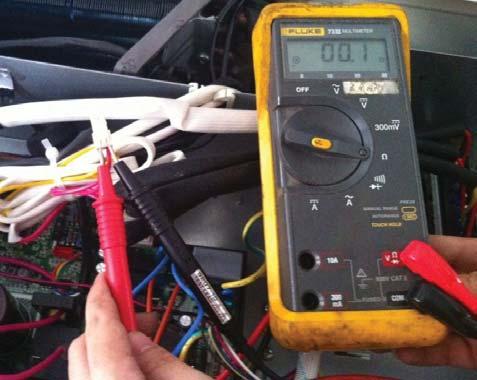
35 Remark Use a multimeter to test the DC voltage between the L2 port and ports of the outdoor unit. (Fig. 31) The red pin of multimeter connects with the L2 port while the black pin is for the port. When the AC is running normally, the voltage will move alternatively between -50V to 50V. If the outdoor unit has a malfunction, the voltage moves alternatively with a positive value. If the indoor unit has a malfunction, the voltage will be a certain value. Example: 10-13VDC small fluctuating amounts indicates indoor unit malfunction. Fig. 31 DC voltage test Remark Use a multimeter to test the resistance of the reactor which does not connect with the capacitor (Fig. 32). The normal values should be around zero ohm. Otherwise, the reactor must have a malfunction and must be replaced. Fig. 32 Reactor resistance test 35
36 Zero crossing detection error diagnosis and solution (E2) Error Code Malfunction decision conditions upposed Causes Troubleshooting: E2 When PCB does not receive zero crossing signal feedback for 4 minutes or the zero crossing signal interval is abnormal Connection mistake PCB faulty 36
37 E1, E2 (Communication malfunction between indoor and outdoor units) error diagnosis and solution. Error Code Malfunction decision conditions upposed Causes E2 Indoor unit does not receive the feedback from outdoor unit during 120 seconds or outdoor unit does not receive the feedback from any one indoor unit during 180 seconds. Wiring mistake Indoor or outdoor PCB faulty Troubleshooting Communica on malfunc on between indoor and outdoor units tart: Power off, then Power on the A/C by the Breaker. (reconnect the power wire). Is it s ll displaying the error code? Check wiring on the outdoor and indoor terminal follow the wiring diagram. Is all connec ng correctly? Reconnect the wiring Reconnect the wiring Turn on all indoor unit by remote controller. Is all indoor unit display Measure Vs, is it moving alternately between posi ve value and nega ve value? (Vs is the voltage between and L2). Refer PIC 1 A: Is all the wiring between terminal and Indoor PCB connect ok? Change the Indoor PCB Turn off the all indoor units. Is IPM power LED or opera ng LED lamp On? Refer PIC2 change IPM Power on by remote controller, IIs it s ll displaying the error code a er 3 minutes? Is main board lamp on? Refer PIC 3. Is the reactor connec ng well Reconnect the wiring Change Outdoor Main PCB Is indoor units number correct? Check on the outdoor check point. (2 for dual zone, 3 for tri zone, 4 for qua zone). Refer PIC 4. Trouble is solved first me second me A Change outdoor unit PCB assembly(include wiring) totally 37

38 Pic 1:Use a multimeter to test the DC voltage between L2 port and port of outdoor unit. The red pin of multimeter connects with L2 port while the black pin is for port. When AC is normal running, the voltage will move alternately between positive value and negative value. Pic 2: :IPM (For dual/tri-zone) Opera ng elf-check 38


39 Pic 2: :IPM (For qua-zone) Power, elf-check Opera ng PIC3 :Main board LED when power on and unit standby. PIC 4: Check point bu on, press 1 me for check how many indoor units are connected. 39
40 E3(Communication malfunction between IPM board and outdoor main board) error diagnosis Error Code Malfunction decision conditions upposed causes E3 PCB main chip does not receive feedback from IPM module during 60 seconds. Wiring mistake PCB faulty Troubleshooting Communication malfunction between IPM board and outdoor main board Is there at least one LED in the IPM board light? Check the signal wire between the IPM module and the main board, is it connected good? Reconnect and retry. Is error still display? Replace IPM board, and then check whether the system can run normally Replace outdoor main board, and then check whether the system can run normally Replace the electric control box Trouble is solved 40


41 Remark: Use a multimeter to test the DC voltage between black pin and white pin of signal wire The normal value should be around 5V. Use a multimeter to test the DC voltage between black pin and red pin of signal wire. The normal value should be around 12V. 41

42 E4 (open or short circuit of outdoor temperature sensor) diagnosis and solution F1/F2/F3/F4/F5 (open or short circuit of indoor coil temperature sensor) diagnosis and solution. Error Code Malfunction decision conditions upposed causes E4/F1/F2/F3/F4/F5 If the sampling voltage is lower than 0.06V or higher than 4.94V, the LED displays the failure. Wiring mistake ensor faulty PCB faulty Troubleshooting Check the connections between temperature sensor and PCB. Are the connections good? Correct the connections. Check the resistance value of the sensor via Appendix 1 and Appendix 2 Is it normal? Replace indoor or outdoor PCB. Replace the sensor 42
43 E5(Voltage protection) error diagnosis and solution. Error Code Malfunction decision conditions upposed causes E5 An abnormal voltage rise or drop is detected by checking the specified voltage detection circuit. Power supply problems ystem leakage or block PCB faulty Troubleshooting Voltage protection Check the voltage of outdoor unit power supply, whether the voltage between L(L1) and N (L2) is about 187~253VAC Check the power supply Check whether the voltage of IPM board P and N is normal? DC V for 18-27KBtu/h; DC V for 36KBtu/h Replace bridge rectifiers, and then check whether the system can run normally(only for quazone) Replace IPM board, and then check whether the system can run normally Replace outdoor main board Trouble is solved 43


44 IPM (for dual/trizone) IPM (for quazone) P-N (for dual/tri-zone) 44

45 45 P-N (for qua-zone)
 qua-zone) 46")
46 bridge rectifier (for dual/tri-zone) bridge rectifier (for qua-zone) 46

47 Remark: Measure the DC voltage between + and - port. The normal value should be 190V~250V. 47
48 E6(PFC module protection) error diagnosis and solution. Error Code Malfunction decision conditions upposed causes E6 When the voltage signal that PFC sends to main control board is abnormal, the display LED displays E6 and the AC turns off. Wiring mistake Outdoor PCB faulty Inductance of PFC module faulty PFC module malfunction Troubleshooting PFC module protection Check whether the connecting line between main board and the PFC module is connected tightly Connect it tightly, check normal or not Check whether the voltage range of P-N on IPM module is normal? DC V for 18-27KBtu/h; DC V for 36KBtu/h Replace the outdoor main board Check whether the inductance of PFC module is good? If the inductance is good, the resistance of the two ports is 0 Replace the inductance Replace the PFC module Trouble is solved 48


49 Inductance Two ports of the inductance 49

50 50
51 E8(Outdoor fan speed has been out of control) diagnosis and solution Error Code Malfunction decision conditions upposed causes E8 When outdoor fan speed keeps too low (300RPM) or too high(2400rpm) for certain time, the unit stops and the LED displays the failure. Wiring mistake Fan ass'y faulty Fan motor faulty PCB faulty Troubleshooting Power off, then restart the unit 3 minutes later. Is it s ll displaying the error code? The unit operates normally. hut off the power supply,, rotate the fan by hand. Does it rotate properly? Find out the cause and have it solved. For example, whether the fan is blocked or the screws which fix the fan are ghten. Check the wiring of fan motor. Are all the connec ons good? Correct the connec ons. Check whether the main PCB is normal through index 1? Replace the main PCB Replace the fan motor 51


52 Index 1: DC fan motor (control chip is inside fan motor) Power on and when the unit is in standby, measure the voltage of pin1 -pin3, pin4 -pin3 in fan motor connector. If the value of the voltage is not in the range showing in below table, the PCB must have problems and need to be replaced. DC motor voltage input and output NO. Color ignal Voltage 1 Red Vs/Vm 200~380V Black GND 0V 4 White Vcc 13.5~16.5V 5 Yellow Vsp 0~6.5V 6 Blue FG 13.5~16.5V Vs Vcc Vsp FG 52
53 P0(Temperature protection of compressor top) error diagnosis and solution. Error Code Malfunction decision conditions upposed causes P0 If the sampling voltage is not 5V, the LED displays the failure. Wiring mistake Over load protector faulty ystem block Outdoor PCB faulty Troubleshooting Temperature protection of compressor top Check the air flow system of indoor and outdoor units Clear up the air inlet and outlet or the heat exchanger of indoor and outdoor units. Power off, then restart the unit 10 minutes later Check whether the temperature of compressor top is more than 100 Check wiring connection of the overload protector Correct the connection. Check the refrigerant volume charge Measure the resistance between the two ports of the OLP. Is it zero? Replace the OLP. Replace the outdoor main PCB. Refrigerant system is blocked, such as capillary or welded point of pipes. Recharge the correct refrigerant volume. 53


54 54
55 P1(High pressure protection) error diagnosis and solution. Error Code Malfunction decision conditions upposed causes P1 If the sampling voltage is not 5V, the LED displays the failure. Wiring mistake Over load protector faulty ystem block Outdoor PCB faulty Troubleshooting High pressure protec on Whether the wiring between the high pressure switch and main control board is connected well or correctly Connect it well Whether the high pressure protector is broken Method: Disconnect the plug. Measure the resistance of the high pressure protector, if the protector is normal the value is o, Replace high pressure protector Check whether the outdoor ambient temperature is higher higher than than 122 F top the unit Check if the outdoor unit l d NO Make the outdoor unit ventilate well Check if the outdoor fan runs properly please ref f fan speed has been out of control malf. Find out the cause and have it solved. Check whether the heat exchanger is dirty Clean the heat exchanger Replace outdoor main board Check whether the refrigerant system is ok 55


56 56
57 P2 (Low pressure protection) error diagnosis and solution Error Code Malfunction decision conditions upposed causes P2 If the sampling voltage is not 5V, the LED displays the failure. Wiring mistake Over load protector faulty ystem block Outdoor PCB faulty Low pressure protec on Whether the wiring between the low pressure protector and main control board is connected well or correctly Connect it well Whether the low pressure protector is broken Method: Disconnect the plug. Measure the resistance of the low pressure protector. If the protector is normal the value is o Replace low pressure protector Check whether the outdoor ambient temperature is too low top the unit Check whether valve core of high pressure valve is opened Check if if the indoor fan runs properly in cooling mode Open fully valve core of high pressure valve please refer to the solution of fan speed has been out of control malfunction. Find out the cause and have it solved. Replace outdoor main board Refrigerant is not enough add the refrigerant Check whether the refrigerant system is ok 57

58 58
59 P3 (Current protection of compressor) error diagnosis and solution. Error Code Malfunction decision conditions upposed causes P3 If the outdoor current exceeds the current limit value, the LED displays the failure. Wiring mistake Over load protector faulty ystem block Outdoor PCB faulty Troubleshooting f compressor Judge 1: Check whether the input current of the power supply wire is more than 12.5A(18K) (For 27K, it is 17.For 30K, it is 18.5.For 36K, it is 23A) Replace outdoor main board Check whether the refrigerant system is ok Judge 2: Check whether the outdoor ambient temperature is higher than F top the unit Judge 3: Check whether the outdoor unit is bad ve la on Make th late well Judge 4: Check whether the heat exchanger is dirty Clean the heat exchanger Judge 5: The refrigerant pipe is blocked Let the refrigerant out, then use the high pressure nitrogen or refrigerant to blow pipe, vacuumize and charge the refrigerant again Replace outdoor main board,and check whether the system can run normally Replace the electric control box Trouble is solved 59


60 60
61 P4(Temperature protection of compressor discharge) error diagnosis and solution. Error Code Malfunction decision conditions upposed causes Troubleshooting P4 When the compressor discharge temperature(t5) is more than 239_F for 10 seconds, the compressor stops and restarts when T5 is less than 194_F. Refrigerant leakage Wiring mistake The discharge temperature sensor faulty Outdoor PCB faulty T compressor discharge f Check whether the compressor discharge temp. is more than 239 F 115 C? Check whether the refrigerant is leak top leaking and add refrigerant Check whether the connection is right between compressor discharge temp. sensor and PCB according to wiring diagrams? Correct the wiring connection Measure the resistance value of compressor discharge temp. sensor. If the value is not normal is normal refer to the Appendix 2? Replace the compressor discharge temp. sensor Replace outdoor main PCB Replace high pressure valve assy 61
62 P5 (High temperature protection of condenser) error diagnosis and solution Error Code P5 Malfunction decision conditions When outdoor pipe temperature is more than 149 F, the unit stops, and unit runs again when the outdoor pipe temperature is less than 125 F. upposed causes The condenser temperature sensor faulty Heat exchanger dirty ystem block Troubleshooting High temperature protec on of condenser Check the connec on between temperature sensor and PCB. Correct the connec on Check whether the condenser temperature is Higher than C F Check C whether the e resistance of condenser temp. sensor is normal refer to the Appendix 1 Replace the temperature sensor Check whether the outdoor ambient temperature is higher than F top the unit Check if the outdoor unit ven la on is good Make the outdoor unit ventilate well Check if the outdoor fan runs properly please refer to the solu on of fan speed has been out of control malfunc on. Find out the cause and have it solved. Check whether the heat exchanger is dirty Clean the heat exchanger Replace outdoor main board Refrigerant is not enough add the refrigerant Check whether the refrigerant system is ok 62
63 P6 (IPM module protection) error diagnosis and solution Error Code Malfunction decision conditions upposed causes P6 When the voltage signal that IPM send to compressor drive chip is abnormal, the display LED shows P6 and the AC turns off. Wiring mistake IPM malfunction Outdoor fan ass y faulty Compressor malfunction Outdoor PCB faulty Troubleshooting IPM module protec on Check whether the voltage range of P-N on IPM module is normal? DC V for 18-27KBtu/h; DC V for 36KBtu/h Check whether the input power supply is correct? V, 1N, 60Hz Regulate it to correct, then check whether the system can work normally? Check whether the connec ng line between main board and the IPM module is connected ghtly Connect it ghtly, check ok or not? Check whether the power supply line is connected correctly and ghtly Connect it correctly and ghtly, check ok or not? Check whether the connec ng line of the compressor is connected correctly or ghtly Connect it well, check ok or not? Check whether the lines in E-part box are connected ghtly Connect it ghtly, check ok or not? Replace the IPM module, check whether the system can work normally? Check if the outdoor fan runs properly or the outdoor unit ven la on is good. Refer to 8.5 Trouble Criterion Of Main Parts, check whether the resistance of the fan motor is normal. If not, replace the fan motor. For other models, refer to the solu on of fan speed has been out of control malfunc on. Find out the cause and have it solved. Check whether the bridge rec fiers are normal? Use the mul meter to measure the resistance between each two terminals, check whether there is the condi on that value of resistance is 0 Check whether the connec ng line of every reactor is normal? If the line is broken, the resistance of the two ports is models except for M4OC-36HRFN1- M Check whether the PFC module broken Replace the bridge rec fiers Replace the main board; check whether the system can work normally? Replace the connec ng line or reactor or replace the PFC module Replace the compressor, check whether the system can work normally? Trouble is solved 63


64 The cooling operation or heating operation does not operate. upposed causes 4 -way valve faulty Check the 4 -way valve. Refer to part 5 in 9.5. When cooling, heat exchanger of non -operating indoor unit frosts. When heating, non -operating indoor unit gets warm. upposed causes: EXV faulty Wire and tubing connected in reverse Check the EXV. Refer to part 6 in 9.5 Trouble Criterion Of Main Parts. IMPORTANT: If you replace outdoor main PCB, you need to check whether the PCB is produced before Apr If yes, you need to short connect OLP connector. Otherwise, the outdoor LED displays P0. 64
65 Temperature sensor checking Disconnect the temperature sensor from PCB, measure the resistance value with a tester. Temperature ensors Room temp.(t1) sensor, Indoor coil temp.(t2) sensor, Outdoor coil temp.(t3) sensor, Outdoor ambient temp.(t4) sensor, Compressor discharge temp.(t5) sensor. Measure the resistance value of each winding by using the multi -meter. 65
66 APPENDIX 1 TEMPERATURE ENOR REITANCE VALUE TABLE (_C-K) KOhm KOhm KOhm KOhm
67 APPENDIX 2 Unit: -K - Discharge Temperature ensor Table B(25/50)=3950K R(90 )=5KΩ±3% APPENDIX
 0.55Ω (20 /68 ) 0.53Ω (20 /68 ) 0.")
68 Compressor Check Measure the resistance value of each winding by using the tester. Position Resistance Value Blue - Red 0.95Ω (20 /68 ) 0.55Ω (20 /68 ) 0.53Ω (20 /68 ) 0.44Ω (20 /68 ) IPM continuity check 68
69 Turn off the power, let the large capacity electrolytic capacitors discharge completely, and dismount the IPM. Use a digital tester to measure the resistance between P and UVWN; UVW and N. rmal resistance rmal resistance Digital tester Digital tester value value (+)Red P (-)Black N U V W (everal MΩ) AC Fan Motor Measure the resistance value of each winding by using the tester. (+)Red U V W (+)Red (-)Black N (everal MΩ) Position Resistance Value RPG20B RPG28H Black - Red 381Ω±8% (68 _F) 342Ω±8% (68 _F) 183.6Ω±8% (68 _F) 180Ω±8% (68 _F) White - Black 267Ω±8% (68 _F) 253Ω±8% (68 _F) 206Ω±8% (68 _F) 190Ω±8% (68 _F) Measure the resistance value of each winding by using the tester. Position Black - 56Ω±8% 24.5Ω±8% 317Ω±8% Resistance Value 145Ω±8% 345Ω±8% 627Ω±8% 88.5Ω±8% Red Red- (68_F) 76Ω±8% (68_F) 19Ω±8% (68_F) 252Ω±8% (68_F) 88Ω±8% (68_F) 150Ω±8% (68_F) 374.3Ω±8% (68_F) 138Ω±8% Yellow Yellow- (68_F) 76Ω±8% (68_F) 19Ω±8% (68_F) 252Ω±8% (68_F) 88Ω±8% (68_F) 150Ω±8% (68_F) 374.3Ω±8% (68_F) 138Ω±8% Blue (68_F) (68_F) (68_F) (68_F) (68_F) (68_F) (68_F) 69


70 4 -Way Valve 1 Power on, use a digital tester to measure the voltage, when the unit operates in cooling, it is 0V. When the unit operates in heating, it is about 230VAC. If the value of the voltage is not in the range, the PCB must have problems and need to be replaced. 2 Turn off the power, use a digital tester to measure the resistance. The value should be 1.8~2.5 KΩ. 70


71 EXV check Disconnect the connectors. Resistance to EXV coil Color of lead wire Red- Blue Red - Yellow Brown-Orange Brown-White rmal Value About 50Ω 71


72 Red- Blue Red - Yellow 72


73 Brown-Orange Brown-White 73
 top operation of the air conditioner and turn OFF the")
 Remove the screws of top crews of top cover cover, and remove the top cover.")
 4) Remove the screws of front panel, and remove the")
74 DIAEMBLY INTRUCTION. Part name Procedures How to remove the panel plate. 1 Panel plate Remarks 1) top operation of the air conditioner and turn OFF the power breaker. 2) Remove the screws of top crews of top cover cover, and remove the top cover. (9 screws) 3) Remove the screws of right front side panel, and remove the right front side panel (2 screws) 4) Remove the screws of front panel, and remove the front panel. (9 screws) crews of rightrear panel crews of front panel 74
 crews of big handle 6) Remove two screws of")


75 5) Remove the screws of big handle, and remove the big handle.(4 screws) crews of big handle 6) Remove two screws of terminal board, four screws of water collector and fourteen screws of rightrear panel, and remove the right-rear panel. crews of water collector crews of terminal board crews of rightrear panel 2 Fan ass y How to remove the fan ass y. 1) Remove the top cover, right front side panel and front panel from item 1.step 1~4 2) Remove the hex nut fixing the fan. 3) Remove the fan. 75
 Disconnect the fan motor connector CN37(5p,white) from the PCB board.")
 Perform work of item 1,2.")
 Unfasten the connector of the compressor.")

76 4) Remove the electrical control box cover. 5) Disconnect the fan motor connector CN37(5p,white) from the PCB board. 6) Remove the fan motor after unfastening four fixing screws. 3 Electrical parts How to remove the electrical parts. 1) Perform work of item 1,2. 2) Remove the ten screws fixing the IPM board. 3) Unfasten the connector of the reactor. IPM board PCB board 4) Unfasten the connector of the compressor. 5) Disconnect following 5 pieces of connection wires and connectors between IPM and PCB. Copyright 2015 CAC/BDP W. Morris t. Indianapolis, IN Edition Date: 08/15 Manufacturer reserves the right to change, at any time, specifications and designs without notice and without obligations. Catalog.38MGQ---01M Replaces: NEW 76
Installation Instructions
 38MHR Outdoor Unit Single Zone Ductless System Sizes 09 to 24 Installation Instructions NOTE: Read the entire instruction manual before starting the installation. NOTE: Images are for illustration purposes
DLCLRA. INSTALLATION INSTRUCTIONS Outdoor Unit Single Zone Ductless System Sizes 36 to 58 TABLE OF CONTENTS
 DLCLRA INSTALLATION INSTRUCTIONS Outdoor Unit Single Zone Ductless System Sizes 36 to 58 Fig. 1 - Size 36 TABLE OF CONTENTS PAGE SAFETY CONSIDERATIONS... 2 PARTS LIST... 3 SYSTEM REQUIREMENTS... 4 WIRING...
Installation Instructions
 38MGQ Multi-Zone Ductless System Sizes 18, 27, 36 and 48 Installation Instructions NOTE: Read the entire instruction manual before starting the installation. TABLE OF CONTENTS PAGE SAFETY CONSIDERATIONS...
Installation Instructions
 38MPRA Outdoor Unit Single Zone Ductless System Sizes 09 to 12 Installation Instructions NOTES: Read the entire instruction manual before starting the installation. Images are for illustration purposes
DLCSRA. INSTALLATION INSTRUCTIONS Outdoor Unit Ductless Split System Sizes 09 to 36 TABLE OF CONTENTS
 DLCSRA INSTALLATION INSTRUCTIONS Outdoor Unit Ductless Split System Sizes 09 to 36 NOTES: Read the entire instruction manual before starting the installation. Images are for illustration purposes only.
Installation Instructions
 40MAQ High Wall Ductless Split System Sizes 09 to 36 Installation Instructions NOTE: Read the entire instruction manual before starting the installation TABLE OF CONTENTS PAGE SAFETY CONSIDERATIONS 2 PARTS
TABLE OF CONTENTS. NOTE: Read the entire instruction manual before starting the installation. TROUBLESHOOTING... 13
 R 410A Duct Free Split System Air Conditioner and Heat Pump Product Family: DFS4(A/H) System, DFC4(A/H)3 Outdoor, DFF4(A/H)H Indoor NOTE: Read the entire instruction manual before starting the installation.
Installation Instructions
 40MBFQ Floor Console Ductless System Sizes 09 to 12 Installation Instructions TABLE OF CONTENTS PAGE SAFETY CONSIDERATIONS... 2 PARTS LIST... 3 SYSTEM REQUIREMENTS... 4 DIMENSIONS... 5 CLEARANCES... 5
Installation Instructions
 40MBFQ Floor Console Ductless System Sizes 09 to 58 Installation Instructions TABLE OF CONTENTS PAGE SAFETY CONSIDERATIONS... 2 PARTS LIST... 3 SYSTEM REQUIREMENTS... 4 WIRING... 4 DIMENSIONS... 5 CLEARANCES...
Installation Instructions
 8GXM / 0GXM Multi---Split High---Wall Duct Free Split System 8GXM --- Size 18k, k, and 0k 0GXM --- Size 9k, 1k, and 18k Installation Instructions NOTE: Read the entire instruction manual before starting
Product Data. 38MG / 40MA / 40MB Multi- Zone Ductless Split System Size 18k, 27k, 36k and 48k INDUSTRY LEADING FEATURES / BENEFITS
 38MG / 40MA / 40MB Multi- Zone Ductless plit ystem ize 18k, 27k, 36k and 48k Product Data INDUTRY LEADING FEATURE / BENEFIT AN INEXPENIVE AND CREATIVE OLUTION TO DEIGN PROBLEM. The 38MG / 40MA / 40MB ductless
Product Data. 38MGQ Multi-Zone Ductless System Sizes 18, 27, 36 and 48 INDUSTRY LEADING FEATURES / BENEFITS
 38MGQ Multi-Zone Ductless ystem izes 18, 27, 36 and 48 Product Data INDUTRY LEADING FEATURE / BENEFIT AN INEXPENIVE AND CREATIVE OLUTION TO DEIGN PROBLEM. The 38MGQ ductless inverter driven multi zone
Installation Instructions
 40MAQ / 38MAQ 619PB / 538PR High---Wall Ductless Split System Sizes 09 to 30 Installation Instructions TABLE OF CONTENTS PAGE PARTS LIST... 2 SAFETY CONSIDERATIONS... 3 SYSTEM REQUIREMENTS... 4 DIMENSIONS...
INSTALLATION INSTRUCTIONS R 410A
 R 410A Ductless Split System Air Conditioner and Heat Pump MODELS: DLC4(A/H) Outdoor, DLF4(A/H) SIZES: 9K, 12K, 18K, 24K, 30K, and 36K NOTE: Read the entire instruction manual before starting the installation.
DLCMRA. INSTALLATION INSTRUCTIONS Multi zone Outdoor Unit Ductless System Sizes 18, 27, 36 and 48 TABLE OF CONTENTS PAGE SAFETY CONSIDERATIONS...
 DLCMRA INSTALLATION INSTRUCTIONS Multi zone Outdoor Unit Ductless System Sizes 18, 27, 36 and 48 TABLE OF CONTENTS PAGE SAFETY CONSIDERATIONS... 2 GENERAL... 2 PARTS LIST... 3 SYSTEM REQUIREMENTS... 4
Installation Instruction
 40GRQ / 619FB / 38GRQ / 538FR High- Wall Ductless Split System Sizes 09-18 Installation Instruction NOTE: Read the entire instruction manual before starting the installation. TABLE OF CONTENTS PAGE SAFETY
Installation Instructions
 38MGR Multi-zone Outdoor Unit Ductless System Sizes 18, 24, 30, 36 and 48 Installation Instructions TABLE OF CONTENTS PAGE SAFETY CONSIDERATIONS... 2 GENERAL... 2 PARTS LIST... 3 SYSTEM REQUIREMENTS...
Installation Instructions
 40MBD Ducted Style Ductless System Sizes 09 to 48 Installation Instructions NOTE: Read the entire instruction manual before starting the installation. TABLE OF CONTENTS PAGE SAFETY CONSIDERATIONS... 2
Product Data INDUSTRY LEADING FEATURES / BENEFITS. 38MA*R Outdoor Unit Single Zone Ductless System Sizes 09 to 36
 38MA*R Outdoor Unit ingle Zone Ductless ystem izes 09 to 36 Product Data INDUTRY LEADING FEATURE / BENEFIT A PERFECT BALANCE BETWEEN BUDGET LIMIT, ENERGY AVING AND COMFORT. The 38MA*R series ductless systems
Service Manual CAUTION ! WARNING SAFETY CONSIDERATIONS INTRODUCTION. 40MFC / 38MFC 40MFQ / 38MFQ High Wall Ductless System Sizes 09 to 22
 40MFC / 38MFC 40MFQ / 38MFQ High Wall Ductless ystem izes 09 to 22 TABLE OF CONTENT PAGE AFETY CONIDERATION... 1 INTRODUCTION... 1 MODEL / ERIAL NUMBER NOMENCLATURE... 2 TANDARD FEATURE AND ACCEORIE...
Installation Instruction
 DLFCAB / DLCCAR / DLFCHB / DLCCHR DLFDAB / DLCDAR / DLFDHB / DLCDHR High- Wall Ductless Split System Sizes 09-36 Installation Instruction NOTE: Read the entire instruction manual before starting the installation.
Installation Instructions
 40MAQ High Wall Ductless System Sizes 09 to 36 Installation Instructions NOTES: Read the entire instruction manual before starting the installation. Images are for illustration purposes only. Actual models
Service Manual CAUTION ! WARNING SAFETY CONSIDERATIONS INTRODUCTION. 38MA*R Outdoor Unit Single Zone Ductless System Sizes 09 to 36
 38MA*R Outdoor Unit Single Zone Ductless System Sizes 09 to 36 Service Manual TABLE OF CONTENTS PAGE SAFETY CONSIDERATIONS... 1 INTRODUCTION... 1 MODEL / SERIAL NUMBER NOMENCLATURES... 2 SPECIFICATIONS...
Product Data INDUSTRY LEADING FEATURES / BENEFITS
 8MGR Multi-zone Outdoor Unit Ductless System Sizes 18, 24, 0, 6 and 48 Fig. 1 18K Fig. 2 24K and 0K Product Data INDUSTRY LEADING FEATURES / BENEFITS A competitively priced and creative solution to design
Product Data. 38GJQ / 40GRQ / 40GJB / 40GJC / 40GJD / 40GJF Multi---Zone Ductless Split System Size 18K, 24K, 30K, 36K, 42K, 48K and 56k
 38GJQ / 40GRQ / 40GJB / 40GJC / 40GJD / 40GJF Multi---Zone Ductless plit ystem ize 18K, 24K, 30K, 36K, 42K, 48K and 56k Product Data INDUTRY LEADING FEATURE / BENEFIT AN INEXPENIVE AND CREATIVE OLUTION
SERVICE MANUAL 42QHF009DS* 42QHF012DS* 42QHF018DS* 42QHF022DS* 38QUS009DS* 38QUS012DS* 38QUS018DS* 38QUS022DS* Indoor unit.
 SERVICE MANUAL Indoor unit Outdoor unit 42QHF009DS* 42QHF012DS* 42QHF018DS* 42QHF022DS* 38QUS009DS* 38QUS012DS* 38QUS018DS* 38QUS022DS* INDEX PART1 GENERAL INFORMATION PART2 ELECTRICAL DIAGRAM PART3 TROUBLE
Service Manual CAUTION ! WARNING INTRODUCTION. 619PB High Wall Ductless System Sizes 09 to 36
 619PB High Wall Ductless System Sizes 09 to 36 Service Manual TABLE OF CONTENTS PAGE SAFETY CONSIDERATIONS... 1 INTRODUCTION... 1 MODEL/SERIAL NUMBER NOMENCLATURES... 2 SPECIFICATIONS... 3 COMPATIBILITY...
Product Data INDUSTRY LEADING FEATURES / BENEFITS
 8MGR Multi-zone Outdoor Unit Ductless System Sizes 18, 24, 0, 6 and 48 Fig. 1 18K Fig. 2 24K and 0K Product Data INDUSTRY LEADING FEATURES / BENEFITS A competitively priced and creative solution to design
CAUTION ! WARNING SAFETY CONSIDERATIONS INTRODUCTION. 38MGR Multi-zone Outdoor Unit Ductless System Sizes 18, 24, 30, 36 and 48
 38MGR Multi-zone Outdoor Unit Ductless System Sizes 18, 24, 30, 36 and 48 TABLE OF CONTENTS PAGE SAFETY CONSIDERATIONS... 1 INTRODUCTION... 1 MODEL/SERIAL NUMBER NOMENCLATURES... 2 SPECIFICATIONS OUTDOOR...
Installation Instructions
 40MHH High Wall Ductless System Sizes 09 to 24 Installation Instructions NOTE: Read the entire instruction manual before starting the installation. NOTE: Images are for illustration purposes only. Actual
Product Data INDUSTRY LEADING FEATURES / BENEFITS. 38MBQ Outdoor Unit Single Zone Ductless System Sizes 36 to 48
 38MBQ Outdoor Unit Single Zone Ductless System Sizes 36 to 48 Product Data INDUSTRY LEADING FEATURES / BENEFITS A PERFECT BALANCE BETWEEN BUDGET LIMITS, ENERGY SAVINGS AND COMFORT. The 38MBQ series ductless
SERVICE MANUAL K LIGHT COMMERCIAL
 SERVICE MANUAL 36 48 60K LIGHT COMMERCIAL Cassette indoor unit Under-ceiling indoor unit Ducted indoor unit 42QTD036DS* 42QTD048DS* 42QTD060DS* 42QZL036DS* 42QZL048DS* 42QZL060DS* 42QSM036DS* 42QSM048DS*
Product Data INDUSTRY LEADING FEATURES / BENEFITS. 40MB*D / 38MAQ / 38MBQ Ducted Split System Sizes 09 to 48
 40MB*D / 38MAQ / 38MBQ Ducted plit ystem izes 09 to 48 Product Data INDUTRY LEADING FEATURE / BENEFIT A PERFECT BALANCE BETWEEN BUDGET LIMIT, ENERGY AVING AND COMFORT. The 40MBD series ducted split systems
Service Manual CAUTION ! WARNING SAFETY CONSIDERATIONS INTRODUCTION 619PB / 538PR HIGH-WALL DUCTLESS SPLIT SYSTEM SIZES 09 TO 30
 619PB / 538PR HIGH-WALL DUCTLE PLIT YTEM IZE 09 TO 30 TABLE OF CONTENT PAGE AFETY CONIDERATION... 1 INTRODUCTION... 1 MODEL / ERIAL NUMBER NOMENCLATURE... 2 TANDARD FEATURE AND ACCEORIE... 3 DIMENION-
Product Data INDUSTRY LEADING FEATURES / BENEFITS. 38MHR Outdoor Unit Single Zone Ductless System Sizes 09 to 24
 38MHR Outdoor Unit ingle Zone Ductless ystem izes 09 to 24 Product Data INDUTRY LEADING FEATURE / BENEFIT A PERFECT BALANCE BETWEEN BUDGET LIMIT, ENERGY AVING AND COMFORT. The 38MHR series ductless systems
CAUTION DLFEHA. SERVICE MANUAL High Wall Ductless System Sizes 09 to 24
 DLFEHA SERVICE MANUAL High Wall Ductless System Sizes 09 to 24 TABLE OF CONTENTS PAGE SAFETY CONSIDERATIONS... 1 INTRODUCTION... 1 MODEL/SERIAL NUMBER NOMENCLATURES... 2 SPECIFICATIONS COOLING ONLY...
KMIR218-H221 / KMIR327-H217 / KMIR436-H217 / KMIR545-H219
 Multi outdoor units SERVICE MANUAL Multi - Zone heat pump units Model Numbers: KMIR218-H221 / KMIR327-H217 / KMIR436-H217 / KMIR545-H219 Table of Contents 1. Indoor Unit Combination 2. Suggested Indoor
Product Data. DLCERA Outdoor Unit Single Zone Ductless System Sizes 09 to 24 INDUSTRY LEADING FEATURES / BENEFITS
 DLCERA Outdoor Unit ingle Zone Ductless ystem izes 09 to 24 Product Data INDUTRY LEADING FEATURE / BENEFIT NOTE: Images are for illustration purposes only. Actual models may differ slightly. TABLE OF CONTENT
Product Data INDUSTRY LEADING FEATURES / BENEFITS. 38MPRA Outdoor Unit Single Zone Ductless System Sizes 09 to 12
 38MPRA Outdoor Unit ingle Zone Ductless ystem izes 09 to 12 Product Data INDUTRY LEADING FEATURE / BENEFIT A PERFECT BALANCE BETWEEN BUDGET LIMIT, ENERGY AVING AND COMFORT. The ductless systems are a matched
Product Data INDUSTRY LEADING FEATURES / BENEFITS. 40MB*D / 38MAQ / 38MBQ Ducted Split System Sizes 09 to 48
 40MB*D / 38MAQ / 38MBQ Ducted plit ystem izes 09 to 48 Product Data INDUTRY LEADING FEATURE / BENEFIT A PERFECT BALANCE BETWEEN BUDGET LIMIT, ENERGY AVING AND COMFORT. The 40MBD series ducted split systems
Product Data INDUSTRY LEADING FEATURES / BENEFITS. 40MB*C / 38MAQ Cassette Ductless Split System Sizes 09 to 18
 40MB*C / 38MAQ Cassette Ductless plit ystem izes 09 to 18 Product Data INDUTRY LEADING FEATURE / BENEFIT A PERFECT BALANCE BETWEEN BUDGET LIMIT, ENERGY AVING AND COMFORT. The 38/40MB*C series ductless
TROUBLESHOOTING TROUBLESHOOTING. Indoor unit EEPROM parameter error. Indoor / outdoor units communication error. Zero-crossing signal detection error
 www.olmo-comfort.com TROUBLESHOOTING When below list for identification of error code occurs, please turn off air conditioner and disconnect power, and then contact the qualified professionals for service.
FROZEN SERIE SERVICE MANUAL. DC Inverter R32. Sistemi per la climatizzazione
 DC Inverter R32 Sistemi per la climatizzazione SERVICE MANUAL FROZEN SERIE CONTENTS 1. General information of Outdoor Units... 3 2. Features... 4 3. Dimensions... 5 4. Refrigeration Cycle Diagram... 6
Product Data INDUSTRY LEADING FEATURES / BENEFITS. 40MB*F / 38MAQ Floor Console Ductless Split System Sizes 09 to 12
 40MB*F / 38MAQ Floor Console Ductless plit ystem izes 09 to 12 Product Data INDUTRY LEADING FEATURE / BENEFIT A PERFECT BALANCE BETWEEN BUDGET LIMIT, ENERGY AVING AND COMFORT. The 40MBF/38MAQ series ductless
SUPER DC INVERTER MULTI TYPE INSTRUKCJA SERWISOWA
 ODMFI-B-1211 INSTRUKCJA SERWISOWA SUPER DC INVERTER MULTI TYPE K2OD-14HFN1-Q, K2OD-18HFN1-Q, K3OD-21HFN1-Q K3OD-27HFN1-Q, K4OD-28HFN1-Q, K4OA-36HFN1-Q K5OC-36HFN1-Q DC MULTI OUTDOOR UNITS CONTENTS 1. General
Installation Instructions
 40MBCQ Cassette Ductless System Sizes 09 to 8 Installation Instructions TABLE OF CONTENTS PAGE SAFETY CONSIDERATIONS... PARTS LIST... 3 SYSTEM REQUIREMENTS... 4 DIMENSIONS INDOOR... 5 CLEARANCES INDOOR...
Product Data INDUSTRY LEADING FEATURES / BENEFITS. 40MB*F / 38MAQ Floor Console Ductless Split System Sizes 09 to 12
 40MB*F / 38MAQ Floor Console Ductless plit ystem izes 09 to 12 Product Data INDUTRY LEADING FEATURE / BENEFIT A PERFECT BALANCE BETWEEN BUDGET LIMIT, ENERGY AVING AND COMFORT. The 38/40MBF series ductless
Multi zone. MULTI OUTDOOR UNITsS. CONDENsSING UNITsS. Revision V1.0: Table of Contents
 MULTI OUTDOOR UNITsS sservice MANUAL Multi zone CONDENsSING UNITsS Revision V1.0: 20160616 Table of Contents 1. Indoor Unit Combination 2. Suggested Indoor Unit Model Numbers 3. Dimension Of Outdoor Unit
Product Data INDUSTRY LEADING FEATURES / BENEFITS. 40MB*C / 38MAQ Cassette Ductless Split System Sizes 09 to 18
 40MB*C / 38MAQ Cassette Ductless plit ystem izes 09 to 18 Product Data INDUTRY LEADING FEATURE / BENEFIT A PERFECT BALANCE BETWEEN BUDGET LIMIT, ENERGY AVING AND COMFORT. The 38/40MB*C series ductless
MULTI INVERTER SERIE H6M
 MULTI INVERTER SERIE H6M Service manual www.mundoclima.com Thank you very much for purchasing our products. Please read this manual carefully before installing and using the unit. ODMFI-B1-1606 CL20440
CAUTION DLCPRA. SERVICE MANUAL Outdoor Unit Single Zone Ductless System Sizes 09 to 12 ! WARNING
 DLCPRA SERVICE MANUAL Outdoor Unit Single Zone Ductless System Sizes 09 to 12 TABLE OF CONTENTS PAGE SAFETY CONSIDERATIONS... 1 INTRODUCTION... 1 MODEL / SERIAL NUMBER MENCLATURES... 2 SPECIFICATIONS HEAT
Product Data INDUSTRY LEADING FEATURES / BENEFITS
 40MB*D Ducted tyle Ductless ystem izes 09 to 48 Product Data INDUTRY LEADING FEATURE / BENEFIT A PERFECT BALANCE BETWEEN BUDGET LIMIT, ENERGY AVING AND COMFORT. The 40MB*D series ducted style ductless
Product Data INDUSTRY LEADING FEATURES / BENEFITS. 40MAQ / 38MAQ High- Wall Ductless Split System Sizes 09 to 30
 40MAQ / 38MAQ High- Wall Ductless plit ystem izes 09 to 30 Product Data INDUTRY LEADING FEATURE / BENEFIT A PERFECT BALANCE BETWEEN BUDGET LIMIT, ENERGY AVING AND COMFORT. The 38/40MAQ series ductless
CAUTION DLFPHA. SERVICE MANUAL High Wall Ductless System Sizes 09 to 12 ! WARNING
 DLFPHA SERVICE MANUAL High Wall Ductless System Sizes 09 to 12 TABLE OF CONTENTS PAGE SAFETY CONSIDERATIONS... 1 INTRODUCTION... 1 MODEL/SERIAL NUMBER MENCLATURES... 2 SPECIFICATIONS... 3 COMPATIBILITY...
Product Data INDUSTRY LEADING FEATURES / BENEFITS. 38MHRB Outdoor Unit Single Zone Ductless System Sizes 09 to 24
 38MHRB Outdoor Unit ingle Zone Ductless ystem izes 09 to 24 Product Data INDUTRY LEADING FEATURE / BENEFIT A PERFECT BALANCE BETWEEN BUDGET LIMIT, ENERGY AVING AND COMFORT. The 38MHRB series ductless systems
Service Manual CAUTION. 40MBDQ Ducted Style Ductless System Sizes 18 to 48 ! WARNING
 40MBDQ Ducted Style Ductless System Sizes 18 to 48 Service Manual TABLE OF CONTENTS PAGE SAFETY CONSIDERATIONS... 1 INTRODUCTION... 1 MODEL SERIAL NUMBER NOMENCLATURES... 2 SPECIFICATIONS... 3 COMPATIBILITY...
Product Data. 38MAQ Outdoor Unit Single Zone Ductless System Sizes 09 to 30 INDUSTRY LEADING FEATURES / BENEFITS
 38MAQ Outdoor Unit Single Zone Ductless System Sizes 09 to 30 Product Data INDUSTRY LEADING FEATURES / BENEFITS A PERFECT BALANCE BETWEEN BUDGET LIMITS, ENERGY SAVINGS AND COMFORT. The 38MAQ series ductless
YC ON-OFF SERIES. Service Manual
 YC ON-OFF SERIES Service Manual CONTENTS 1. Precaution... 3 1.1 Safety Precaution... 3 1.2 Warning... 3 2. Model Lists... 6 3. Dimension... 7 3.1 Indoor Unit... 7 3.2 Outdoor Unit... 11 4. Refrigerant
Product Data INDUSTRY LEADING FEATURES / BENEFITS. 40MVC / 38MVC 40MVQ / 38MVQ High---Wall Duct Free Split System Sizes 009 to 024
 40MVC / 38MVC 40MVQ / 38MVQ High---Wall Duct Free plit ystem izes 009 to 024 Product Data INDUTRY LEADING FEATURE / BENEFIT AN INEXPENIVE AND CREATIVE OLUTION TO DEIGN PROBLEM. The 38/40MVC(Q) series duct-free
HEAT PUMP INSTALLATION MANUAL
 DUCTLESS INVERTER HEAT PUMP INSTALLATION MANUAL Models: TERRA09HP230V1A TERRA12HP230V1A TERRA18HP230V1B TERRA24HP230V1B Thank you for choosing a Gree Terra Ductless Heat Pump for your customer. Please
SERVICE MANUAL Room Air Conditioner DC Inverter Multi Split Outdoor units
 SERVICE MANUAL Room Air Conditioner DC Inverter Multi Split Outdoor units FS2MIF-140AE2 FS2MIF-180AE2 FS3MIF-210AE2 FS3MIF-270AE2 FS4MIF-280AE2 FS4MIF-360AE2 FS5MIF-360AE2 NOTE: Before servicing the unit,
PERFORMANCE DATA Model Numbers Cooling High Heating 47 F Low Heating 17 F
 ENVIRONMENTALLY OUND REFRIGERANT DLC4(A/H)6 Outdoor DLF4(A/H)6 Indoor Product pecifications DUCTLE HIGH WALL PLIT YTEM, R 410A Efficient 16 EER Air Conditioners and Up to 8.6 HPF Heat Pumps 3/4 thru 2
DuctlessAire ES Series. Service Manual 2016 ABSSA-B4-1601
 DuctlessAire ES Series Service Manual 2016 ABSSA-B4-1601 CONTENTS 1. Precaution... 1 1.1 Safety Precaution... 1 1.2 Warning... 1 2. Model list... 4 3. Dimension... 5 3.1 Indoor Unit... 5 3.2 Outdoor Unit...
Product Data INDUSTRY LEADING FEATURES / BENEFITS. 40GVC / 38GVC 40GVQ / 38GVQ High---Wall Ductless Split Systems Size 009K K
 40GVC / 38GVC 40GVQ / 38GVQ High---Wall Ductless plit ystems ize 009K --- 036K Product Data INDUTRY LEADING FEATURE / BENEFIT AN INEXPENIVE AND CREATIVE OLUTION TO DEIGN PROBLEM. The 38GVC(Q)/40GVC(Q)
Product Data INDUSTRY LEADING FEATURES / BENEFITS
 40MBFQ Floor Console Ductless ystem izes 09 to 12 Product Data INDUTRY LEADING FEATURE / BENEFIT A PERFECT BALANCE BETWEEN BUDGET LIMIT, ENERGY AVING AND COMFORT. The 40MBFQ series ductless system are
Product Data. 38GJQ MULTI-ZONE DUCTLESS SYSTEM MATCHED WITH 40GRQ / 40GJB / 40GJC / 40GJD / 40GJF Indoor Units Sizes 18, 24, 30, 36, 42, 48 and 56
 38GJQ MULTI-ZONE DUCTLESS SYSTEM MATCHED WITH 40GRQ / 40GJB / 40GJC / 40GJD / 40GJF Indoor Units Sizes 18, 24, 30, 36, 42, 48 and 56 Product Data INDUSTRY LEADING FEATURES / BENEFITS AN INEXPENSIVE AND
Service Manual CAUTION
 38MHR Outdoor Unit Single Zone Ductless System Sizes 09 to 24 Service Manual TABLE OF CONTENTS PAGE SAFETY CONSIDERATIONS... 1 INTRODUCTION... 1 MODEL/SERIAL NUMBER NOMENCLATURES... 2 SPECIFICATIONS...
Product Data. 38GXM / 40GXM Multi---Split High---Wall Duct Free Split System 38GXM --- Size 18k, 24k, and 30k 40GXM --- Size 9k, 12k, and 18k
 38GXM / 40GXM Multiplit HighWall Duct Free plit ystem 38GXM ize 18k, 24k, and 30k 40GXM ize 9k, 12k, and 18k Product Data NOTE: Read the entire instruction manual before starting the installation. INDUTRY
Product Data. 38GVM / 40GVM Multi---Split High---Wall Ductless Split System 38GVM --- Size 18k, 24k, 30k, 36k and 42k 40GVM --- Size 9k, 12k, and 18k
 38GVM / 40GVM Multi---plit High---Wall Ductless plit ystem 38GVM --- ize 18k, 24k, 30k, 36k and 42k 40GVM --- ize 9k, 12k, and 18k Product Data INDUTRY LEADING FEATURE / BENEFIT AN INEXPENIVE AND CREATIVE
Residential Piping and Long Line Guideline
 AC / HP R-410A Refrigerant Systems Single-Stage, Two-Stage and Variable Speed Models Residential Piping and Long Line Guideline TABLE OF CONTENTS Safety Considerations... 2 Definitions... 2 Introduction...
Installation Instructions Read and become familiar with these instructions before beginning installation.
 KSAIC005 (5V) KSAIC00230 (208-230V) 24V Interface Kit for Ductless Systems Installation Instructions Read and become familiar with these instructions before beginning installation. SAFETY CSIDERATIS Read
Product Data INDUSTRY LEADING FEATURES / BENEFITS. DHCMA / DACMA DHQMA / DAQMA High Wall Ductless System Sizes 09 to 22
 DHCMA / DACMA DHQMA / DAQMA High Wall Ductless ystem izes 09 to 22 Product Data INDUTRY LEADING FEATURE / BENEFIT A PERFECT BALANCE BETWEEN BUDGET LIMIT, ENERGY AVING AND COMFORT. The DACMA/DHCMA DAQMA/DHQMA
WMHP Series R410a Heat Pump INSTALLATION INSTRUCTIONS
 WMHP Series R410a Heat Pump INSTALLATION INSTRUCTIONS **WARNING TO INSTALLER, SERVICE PERSONNEL AND OWNER** Altering the product or replacing parts with non authorized factory parts voids all warranty
YN-M SERIES MULTI SPLIT SYSTEM MULTI CIRCUIT OUTDOOR UNITS (2, 3 AND 4 ZONES) SERVICE MANUAL PRE 2014 MODELS (Pre Serials) CONDENSING UNITS
 SERVICE MANUAL PRE 2014 MODELS (Pre Serials) CONDENSING UNITS") YN-M SERIES MULTI SPLIT SYSTEM MULTI CIRCUIT OUTDOOR UNITS (2, 3 AND 4 ZONES) SERVICE MANUAL PRE 2014 MODELS (Pre 50130047 Serials) CONDENSING UNITS Parker Davis HVAC International, Inc. Revision B: ODMI
YN-M SERIES MULTI SPLIT SYSTEM MULTI CIRCUIT OUTDOOR UNITS (2, 3 AND 4 ZONES) SERVICE MANUAL PRE 2014 MODELS (Pre 50130047 Serials) CONDENSING UNITS Parker Davis HVAC International, Inc. Revision B: ODMI
Bosch Split-Type Ductless Air Conditioner / Heat Pump
 Bosch Split-Type Ductless Air Conditioner / Heat Pump Climate 5000 AA Series Service Manual 2 Bosch Climate 5000 AA Series Split Type Ductless Air Conditioner / Heat Pump Service Manual Data subject to
Installation Instructions Read and become familiar with these instructions before beginning installation.
 KSAIC020230 (208-230V) 24V Interface Kit for Ductless Outdoor Single Zone matched with Air Handler Installation Instructions Read and become familiar with these instructions before beginning installation.
Part 3 Troubleshooting
 Part Troubleshooting What is in this part? This part contains the following chapters: Chapter See page Troubleshooting 2 Error Codes: Hydro-box 7 Error Codes: Outdoor Units Error Codes: System Malfunctions
Service Manual CAUTION. 38MAQ Outdoor Unit Single Zone Ductless System Sizes 09 to 30 ! WARNING SAFETY CONSIDERATIONS
 38MAQ Outdoor Unit Single Zone Ductless System Sizes 09 to 30 TABLE OF CONTENTS PAGE SAFETY CONSIDERATIONS... 1 INTRODUCTION... 1 MODEL/SERIAL NUMBER NOMENCLATURES... 2 SPECIFICATIONS... 3 DIMENSIONS...
Multi zone Two, Three, Four and Five Zones
 MULTI SPLIT SYSTEM OUTDOOR UNITS SERVICE MANUAL Multi zone Two, Three, Four and Five Zones DC INVERTER MULTI ZONE OUTDOOR UNITS Revision A: ODMI E 1601 PDB55/2016 Model Numbers: YN020GMFI22M2D YN030GMFI22M3D
Product Data INDUSTRY LEADING FEATURES / BENEFITS
 0MHH High Wall Ductless ystem izes 09 to 2 Product Data INDUTRY LEADING FEATURE / BENEFIT A PERFECT BALANCE BETWEEN BUDGET LIMIT, ENERGY AVING AND COMFORT. The 0MHH series ductless systems are a matched
Product Data INDUSTRY LEADING FEATURES / BENEFITS. 40GXC / 38GXC 40GXQ / 38GXQ Inverter---Driven High Wall Duct---Free Split System Sizes 009 to 024
 40GXC / 38GXC 40GXQ / 38GXQ InverterDriven High Wall DuctFree plit ystem izes 009 to 024 Product Data The ideal compliment to your ducted system when it is impractical or prohibitively expensive to use
Owner s Manual TABLE OF CONTENTS
 40MBD / 38MAQ / 38MBQ Ducted tyle Ductless plit ystem izes 09 to 48 Owner s Manual TABLE OF CONTENT PAGE A NOTE ABOUT AFETY... 2 GENERAL... 2 PART LIT... 3 DIPLAY PANEL... 4 REMOTE CONTROL... 6 REMOTE
Product Data INDUSTRY LEADING FEATURES / BENEFITS. 40GRQ / 38GRQ High- Wall Ductless Split System Sizes 09 to 18
 40GRQ / 38GRQ High- Wall Ductless plit ystem izes 09 to 18 Product Data INDUTRY LEADING FEATURE / BENEFIT A PERFECT BALANCE BETWEEN BUDGET LIMIT, ENERGY AVING AND COMFORT. The 38/40GRQ series ductless
Product Data INDUSTRY LEADING FEATURES / BENEFITS
 40MKCF / 24AHA4 / 124AN 40MKQF / 25HHA4 / 224AN Under Ceiling/Floor Console Ductless ystem izes 18 to 54 Product Data INDUTRY LEADING FEATURE / BENEFIT A PERFECT BALANCE BETWEEN BUDGET LIMIT, ENERGY AVING
Service manual. MIV V4+ Mini
 DM12-01.01.05en Service manual MIV V4+ Mini DC INVERTER R410A (~220V, 50Hz, 1Ph) MVUH80A-VA1 Contents Part 1 General Information... 1 Part 2 Outdoor Units... 6 Part 3 Installation... 44 DM12-01.01.05en
Product Data INDUSTRY LEADING FEATURES / BENEFITS. 40GRQ / 38GRQ High Wall Ductless Split System Sizes 09 to 18
 40GRQ / 38GRQ High Wall Ductless plit ystem izes 09 to 18 Product Data INDUTRY LEADING FEATURE / BENEFIT A PERFECT BALANCE BETWEEN BUDGET LIMIT, ENERGY AVING AND COMFORT. The 38/40GRQ series ductless split
Dream Inverter Series. Service Manual 2017
 Dream Inverter Series Service Manual 2017 CONTENTS 1. Precaution... 3 1.1 Safety Precaution... 3 1.2 Warning... 3 2. Model List... 6 3. Dimension... 7 3.1 Indoor Unit... 7 3.2 Outdoor Unit... 11 4.Refrigerant
DC INVERTER MULTI-SYSTEM AIR CONDITIONER
 TECHNICAL & SERVICE MANUAL OUTDOOR UNIT : CU-3KE19NBU CU-4KE24NBU CU-4KE31NBU DC INVERTER MULTI-SYSTEM AIR CONDITIONER Capacity at 0V 19,100 BTU/h,200 BTU/h 30,600 BTU/h Outdoor Model No. CU-3KE19NBU CU-4KE24NBU
Installation Instructions
 24AHA4 Performance Series Air Conditioner with Puron Refrigerant 1-1/2 to 5 Nominal Tons Installation Instructions Fig. 1-24AHA4 A07532 SAFETY CONSIDERATIONS Improper installation, adjustment, alteration,
HABITAT USER MANUAL TIN310**V33 TIN414**V33 TIN520**V33 TIN625**V33 TIN1036H2V02 TIN1939H2V02 INVERTER MINI SPLIT
 HABITAT INVERTER MINI SPLIT USER MANUAL TIN310**V33 TIN414**V33 TIN520**V33 TIN625**V33 TIN1036H2V02 TIN1939H2V02 WARNING The information contained in the manual is intended for use by a qualified service
Mission 3D Inverter Series
 Mission 3D Inverter Series Service Manual 2014 MBSEU-A-1412 CONTENTS 1. Precaution... 3 1.1 Safety Precaution... 3 1.2 Warning... 3 2. Function... 6 3. Dimension... 7 3.1 Indoor Unit... 7 3.2 Outdoor Unit...
Product Data. High --- Wall Duct --- Free Split systems INDUSTRY LEADING FEATURES / BENEFITS
 High --- Wall Duct --- Free plit systems PA13A / PW3CA Cooling izes 009---012 PA13N / PW3CN Cooling izes 018---024 PH13A / PW3HA HP izes 009---012 PH13N / PW3HN HP izes 018---024 Product Data INDUTRY LEADING
Installation Instructions
 50ZPB, C, 50ZHB, C, PA3Z ---A, PH3Z ---A, PA4Z, PH4Z, PAJ4,PHJ4,WJA4,WJH4 SMALL PACKAGED PRODUCTS (SPP) Accessory Electric Heaters 5---20 kw For 14 SEER, R---410A Manufactured Home Installation Instructions
Product Data INDUSTRY LEADING FEATURES / BENEFITS
 40MKCF / 24AHA4 / 124AN 40MKQF / 25HHA4 / 224AN Under Ceiling/Floor Console Ductless ystem izes 18 to 54 Product Data INDUTRY LEADING FEATURE / BENEFIT A PERFECT BALANCE BETWEEN BUDGET LIMIT, ENERGY AVING
HIGH-WALL DUCTLESS AIR CONDITIONING & HEATING SYSTEM INSTALLATION MANUAL
 HIGH-WALL DUCTLESS AIR CONDITIONING & HEATING SYSTEM INSTALLATION MANUAL Models: RIO09HP115V1A RIO12HP115V1A RIO09HP230V1B RIO12HP230V1B RIO18HP230V1B RIO24HP230V1A Thank you for choosing a Rio Heat Pump
DC INVERTER MULTI-SYSTEM AIR CONDITIONER
 TECHNICAL & SERVICE MANUAL OUTDOOR UNIT : CLM97 CLM7 CLM7 FILE NO. Destination: North America DC INVERTER MULTI-SYSTEM AIR CONDITIONER Capacity at 0V 9,700 BTU/h,00 BTU/h 0,600 BTU/h Outdoor Model No.
Part 5. Troubleshooting. 1. Normal Air Conditioner Phenomenon Air Conditioner Protection in Common
 Part 5 1. Normal Air Conditioner Phenomenon... 1611 2. Air Conditioner Protection in Common... 1611 3. Malfunction Code and... 162 160 1. Normal Air Conditioner Phenomenon 1.1 When outdoor unit appears
KSIM20912-H216 KSIM30912-H216 KSIM40912-H216
 SERVICE MANUAL KLIMAIRE AIRCONDITIONER KSIM DC INVERTER MULTI TYPE KSIM20912-H216 KSIM30912-H216 KSIM40912-H216 DC MULTI OUTDOOR UNITS CONTENTS 1. General information of Outdoor Units...3 2 Features...4
Service Manual CAUTION ! WARNING SAFETY CONSIDERATIONS INTRODUCTION
 40MKCF / 24AHA4 / 124AN 40MKQF / 25HHA4 / 224AN Under Ceiling/Floor Console Ductless ystem izes 18 to 54 ervice Manual TABLE OF CONTENT PAGE AFETY CONIDERATION... 1 INTRODUCTION... 1 MODEL / ERIAL NUMBER
Installation Instructions
 Electric Heater Kit For use with GB, GP and GT eries Geothermal Heat Pumps KWAEH0101N05 KWAEH0101N10 KWAEH0101F15 KWAEH0101F20 Installation Instructions NOTE: Read the entire instruction manual before