Description of functions
|
|
|
- Basil Goodwin
- 6 years ago
- Views:
Transcription
1 Description of functions Laddomat 21 is designed to......allow the boiler to reach a high working temperature soon after firing....to preheat the cold tank water in the bottom of the boiler so that the boiler does not rust away due to condensation. charge the tank with water at a high and even temperature and low flow, to ensure optimal layering in the tank. transfer the residual heat in the boiler to the tank after the fire has gone out. in the event of electrical power failure stopping the pump, transfer the heat in the boiler to the tank through self-circulation. Operation Laddomat 21 functions fully automatically provided that pump start and stop is automated. See page 16. The settings described in this User manual are normally made only once. The Laddomat requires no special supervision or service. NOTE! Diagrams in this brochure only describe connection principles. Each installation must be measured and carried out according to the applicable regulations. Start up Operating phase Final phase Connection to top of boiler Self-circulation Technical data Laddomat Pump: Laddomat LM6 Laddomat LM6A ErP 2015 Connection: Opening temperature: Max. boiler output: 3 x Cu28 with lever 3 x R32 with lever 53, 57, 63, 66, 72, 78, 83 or 87 C 60 kw Technical data Laddomat Pump: Wilo RS25-7 Wilo Yonos Para ErP 2015 Connection to bottom of boiler Connection to bottom of tank Connection: Opening temperature: 3 x R32 with lever 53, 57, 63, 66, 72, 78, 83 or 87 C Max. boiler output: 120 kw 1
2 Dimensioning Generous pipe dimensions and short lengths guarantee operating reliability, even when the demand for heat is high. This also allows effective self-circulation in the event of power failure. Recommended pipe dimensions for a maximum boilerto-tank distance of 2 m. Total length boiler-tank-boiler would then be m + 6 bends. 1 bend is equivalent to 1 m pipe length. Boiler with max output* up to: Laddomat 21-60: 45 kw min. 28 Cu pipe or R25 60 kw min. 35 Cu pipe or R32 Laddomat : 80 kw min. 35 Cu-rör alt. R kw min. 42 Cu-rör alt. R kw min. 54 Cu-rör alt. R50 Flow: At the above pipe dimensions, Laddomat gives 2 3 m³/h. Laddomat gives 3 4m³/h. See flow diagram below. The dimensions must be increased for longer distances. The maximum distance between boiler and tank is 6 m. Total length would then be m + 6 bends. Maximum distance and self-circulation With longer distance, the Laddomat should be placed closer to the accumulator. Remember that flow capacity will decrease, both when it comes to pump flow as well as self-circulation. See example on page 6. If there are special requirements for self-circulation, the pipes must be dimensioned accordingly. Example: If the boiler s nominal output is 40 kw, the max output can reach up to 60 kw. This is very important to include in the calculation when dimensioning the system. Connection Laddomat 21 must always be connected in the upright position as shown in the diagrams. Place Laddomat 21 near the boiler and at the level of the boiler s bottom output. Pipe-runs must be as short as possible and have the minimum number of bends. Make sure that all air pockets are eliminated. The diameter of the pipe from the top of the boiler to the T-pipe and down to the Laddomat 21 must be as large as possible. This gives low water velocity, and allows air released in the boiler to separate out in the expansion chamber or the vent. Starting and stopping the charging pump The speed control on the circulation pump must be in position 3. NOTE! Check that the control is not at the lowest speed or a neutral position because this can prevent the pump from starting. The pump can be started by a flue thermostat. If extra safety is required, a water thermostat can be connected in parallel. See image to the right. Expansion vessel The expansion vessel must be sufficiently large, at least 5 10% of the total volume for an open system. If a pressure vessel is installed, this must be at least 10 20% of the total volume. Each installation must be specially dimensioned in accordance with the manufacturer s instructions. Check that the operating pressure, when the system is cold, is never lower than the height difference between the pressure gauge and the highest radiator + 2 metre water pillar (mwp, 1 m = 0,1 bar). *Boiler output: There is a difference between the nominal output and the maximum output of a boiler. The maximum output can be as much as 30-50% higher than the boiler s nominal output. 2 Radiator system To make the maximum use of the storage tank, it is very important that the radiator system is fitted with: 1. Automatic by-pass control like Thermomatic with flow sensor and room sensor is ideal for this purpose, thanks to its ability to sense the heating needs of the house rapidly. The automatic by-pass control always matches heat output exactly to requirements. 2. Thermostatic valves with integrated pressure reduction devices, which are set to suit the radiator size. Both measures are intended to reduce the flow and so reduce the return temperature, without raising the delivery temperature. The lower the return temperature, the longer the heat in the tank lasts.
3 Connecting to 1 tank 1. The pipe-runs shown on the diagram are optimised to minimise air-related operating interruptions. 2. The hot water pipe to the by-pass valve can be connected in two ways. A. Approx 30 cm from the top of the tank to prioritise domestic hot water. B. On the charge line connection to the tank to prioritise heating. The connection is directed downwards to prevent air rising to the radiators. Laddomat 21 can easily be reversed for right-hand mounting. Just move the thermometers to the other side. Connecting 2 tanks The tanks must be located up against each other, and as close as possible to the boiler. The pipe-runs from the bottom of the tanks are always laid close to the floor. It is important that the flow to the tanks during charging and discharging is distributed equally. If the system is connected incorrectly, then charging will be cut off when tank 1 is full of hot water which will reach the boiler before the other tanks are completely filled. Tank 2 will be virtually unused. If the system is connected incorrectly, the warm water and the heat will run out earlier than estimated after the burner has stopped, since tank 1 will cool down more quickly than the other. If these requirements cannot be met, there are other connection options. NOTE If the radiator is connected in this way there is a large risk of heat retention in the boiler and/or reduced heat to the radiator circuit. The pipe to the bottom of the tank must not be routed through the roof. This connection removes the selfcirculation function. Equal pipe lengths To achieve equal resistance, it is essential to use approximately the same pipe-lengths to the tanks, this is achieved by: 1. Connecting the charging circuit diagonally, A A. 2. Connecting the radiator circuit diagonally, B B. In addition, the dimension of the pipes between the tanks must be large enough to facilitate self-circulation between the tanks. It is an advantage if the tanks are connected together in the centre, to further distribute the heat. Connecting the by-pass valve The hot water port is connected at B, which prioritises hot water, or at B 1, which prioritises heating. Electrical immersion heater operation When operating solely on the electrical immersion heater, it is an advantage only to heat the first tank to prevent heat loss. Shut off the other tank using the valve at the bottom of the tank. 3
4 Connection suggestions NOTE This type of installation will remove the selfcirculation function. The check valve must be blocked to lower the risk of keeping the boiler warm. See picture 5 on next page for instruction. Recommended installation with longer distance To make sure the charging will work, the Laddomat should be placed near the accumulator. NOTE long distance means lower flow, which means lower capacity for the system. Bottom connection of the expansion vessel gives reduced heat losses. NOTE See information on page 16 about the expansion vessel Alternative installation with open expansion vessel 4


. Push the new thermostat into the plunger.")

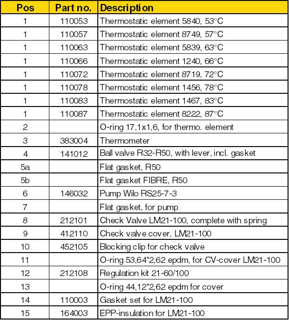
5 Thermostat cartridge The thermostat cartridge is available as a spare part, and may need to be replaced more often if it is regularly exposed to temperatures close to, or above, boiling point. The number is engraved on the cartridge. See spare parts list for options Service Before carrying out any servicing work, close the three shutoffs by turning the lever on the valves at right angles to the direction of the pipe. This makes it easy to access the pump, thermal valve and check valve for service. If operating interruptions still occur, even though the system has been bled, there may be dirt such as lint, tape or thread swarf stuck in the coupling. Disassemble and clean. Clean all sealing surfaces when reassembling: 1. The thermal valve 2. The self-circulation valve 3. The pump impeller In some installations, there are problems with extremely high levels of contaminants. These can form deposits inside the pump, which may result in stoppages. Picture1 Instructions for replacing the thermostat in Laddomat 21 Check that the pump is switched off. Close the three shut-off valves. Unscrew the cover opposite the pump. Remove the cover with the spring, plunger and thermostat from Laddomat 21. The thermostat is held in place on the plunger by an O- ring. Detach the thermostat from the plunger carefully using a screwdriver (see image on right). Push the new thermostat into the plunger. Reinstall the cover with the spring, plunger and thermostat. Open the shut-off valves. Wait a few minutes before starting the pump to allow any air to rise and escape from the system. The installation is now ready for use. Picture 3 Picture 2 The blocking clip is mounted here. Blocking the check valve If you, for some reason, want to completely shut off the self circulation function, the check valve must be blocked. Use the blocking clip, placed at the bottom of the EPPinsulation (Picture 3), to block the check valve. The clip is then fastened around the check valve axis according to picture 5. To reach the axis, the spring needs to be removed. Picture 4 Picture 5 Laddomat Blocking clip Laddomat
6 Installation & setting pump Laddomat LMXA Blue Green Yellow Blue Laddomat LM6A I 7-50 W 16 W II W 34 W III W 50 W 230 V ± 10 %, 50 Hz 6

7 7

8 8
Description of functions
 Description of functions EN Laddomat 21 is designed to......allow the boiler to reach a high working temperature soon after firing....to preheat the cold tank water in the bottom of the boiler so that
Manual and installation instructions. Function. Operating phase
 LADDOMAT M120 Manual and installation instructions Thermal layering Function Thanks to its design and control features, the Laddomat M120 means optimal thermal layering in storage tanks, with a low and
Laddomat. Mixing valves for solid fuel boilers. Version 1.01
 Laddomat Mixing valves for solid fuel boilers Version 1.01 Laddomat > Mixing valves for solid fuel boilers Why Laddomat This is the answer to those who burn wood or pellets and wonder why you should complement
INSTALLATION, OPERATION AND MAINTENANCE. Ariterm Vedo
 INSTALLATION, OPERATION AND MAINTENANCE Ariterm Vedo CONTENTS General...3 Installation...4-5 Laddomat 21 Connection diagram...6 Temperature control valve...7 About burning wood...8 Operation...9-11 Service
User & Installation instruction
 LADDOMAT MR 40 User & Installation instruction Scope of delivery Valve package Laddomat 41-100 with: Charge and discharge valve with 2 non-return valves and thermal three-way valve. 2 pumps, LM6A-130.
Product range Code HE1 Connection and energy management compact unit without anti-condensation valve
 Connection and energy management compact unit 2850 series ACCREDITED CALEFFI 01259/14 GB ISO 9001 FM 21654 ISO 9001 No. 0003 Function The connection and energy management compact unit enables combining
INSTALLATION AND OPERATING INSTRUCTIONS
 INSTALLATION AND OPERATING INSTRUCTIONS CONTENTS 2 6 7 8 9 10-12 16 17 18 18 19 2 GENERAL TRANSPORTATION, STORAGE AND OPENING THE PACKAGE Receiving the goods - Storage Opening the package 3 INSTALLATION
INSTALLATION AND OPERATING INSTRUCTIONS. Ariterm 60+
 INSTALLATION AND OPERATING INSTRUCTIONS Ariterm 60+ CONTENTS General.... 2 Installation.... 4-5 Installation of temperature limit valve... 6 Measurements and connections... 7 Technical specifications and
Installation instructions
 LADDOMAT MR 30 Installation instructions Scope of delivery Sys 30: Art no. 11 34 31 02 Laddomat MR, complete. Spring-loaded non-return valve BV FB40-T Charge pump LM6A-130, with 2 x shut-off valves Cu28
sustainable energy solutions
 sustainable energy solutions EN Why Laddomat? 6 7 Laddomat 21-series 8 9 Laddomat 11-series NEW! 10 11 Laddomat 11 Duo NEW! 12 Laddomat 11-30 FDV 13 Laddomatic NEW! 14-15 Laddomat M120 16 Laddotank NEW!
PLEASE LEAVE THIS MANUAL WITH THE OSO UNIT AFTER INSTALLATION INSTALLATION MANUAL
 PLEASE LEAVE THIS MANUAL WITH THE OSO UNIT AFTER INSTALLATION SOLARCYL IM/SC INSTALLATION MANUAL This manual gives detailed advice for installation and should be read carefully prior to fitting any unvented
CALEFFI. Anti-condensation recirculation and distribution unit. 281 series 01224/14 GB. Replaces dp 01224/12 GB. Function
 Anti-condensation recirculation and distribution unit 8 series ACCREDITED ISO 900 FM 654 ISO 900 No. 000 CALEFFI 04/4 GB Replaces dp 04/ GB GB Function The anti-condensation recirculation and distribution
PLEASE LEAVE THIS MANUAL WITH THE OSO UNIT AFTER INSTALLATION INSTALLATION MANUAL
 PLEASE LEAVE THIS MANUAL WITH THE OSO UNIT AFTER INSTALLATION 0 RD 0 RI 0000-06 IM/ IM/a INSTALLATION MANUAL This manual gives detailed advice for installation and should be read carefully prior to fitting
BioMaster 250/350/600 BioMaster Thermo 250/350/600
 Downloaded from www.watergardeningdirect.com BioMaster 250/350/600 BioMaster Thermo 250/350/600 A BMR0003 B BMR0004 2 BioMaster 250/350/600, BioMaster Thermo 250/350/600 C D BMR0021 BMR0022 3 Downloaded
Trade Product List 2013 BIOMASS ACCESSORIES
 Trade Product List 2013 BIOMASS ACCESSORIES BIOMASS SYSTEM COMPONENTS Constant Temperature Control Accessories CONSTANT TEMPERATURE CONTROL PRODUCTS Order Code Description of Package and Contents Pictures
JANUS 3 CIRCULATOR WATER HEATER INSTALLATION, COMMISSIONING & SERVICING INSTRUCTIONS G.C. No
 JANUS 3 CIRCULATOR WATER HEATER INSTALLATION, COMMISSIONING & SERVICING INSTRUCTIONS G.C. No 53 416 06 Publication No. ZZ 180/17 May 2000 These appliances are tested and certified by B G Technology for
Installation, operation and care Firewood boiler Vedolux 40 UB
 Installation, operation and care Firewood boiler Vedolux 40 UB 2008-09-23 Ver 2 Replaces: 05-11 VEDOLUX 40 UB Notes 0809 To be completed when the Vedolux 40 UB is installed Serial number:... Installation
USER'S MANUAL PGE Single Package Rooftop
 USER'S MANUAL PGE Single Package Rooftop Gas Heating/Electric Cooling Units Sizes 036-150 3 to 12-1/2 Tons NOTE TO INSTALLER: This manual should be left with the equipment owner. WARNING: If the information
Installation, operation and care. Pellmax UB. Burner not included Replaces:
 Installation, operation and care Burner not included 2011-11-11 ver: Replaces: Contents 11.11 otes...3 General...4 Function...4 Technical data...5 System principle Pellmax with radiator and tank-in-tank
A AD Oil burners fuel unit. deltapumps.com. DE A-AD_en_0709.pdf Page 1/1
 A AD Oil burners fuel unit deltapumps.com DE116-0709 A-AD_en_0709.pdf - 16.11.09 Page 1/1 Oil burners fuel unit Type A, AD 1- Applications The DELTA aluminium fuel unit type A is an efficient and modern
INSTALLATION MANUAL. Ecoline Geo RI HP PLEASE LEAVE THIS MANUAL WITH THE OSO UNIT AFTER INSTALLATION
 PLEASE LEAVE THIS MANUAL WITH THE OSO UNIT AFTER INSTALLATION Ecoline Geo RI HP INSTALLATION MANUAL The Ecoline GEO is an indirect unvented cylinder designed and approved for use with a heat pump. The
Remeha. Fuel oil/gas boilers P 520. Installation and Service Manual A
 Remeha Fuel oil/gas boilers EN Installation and Service Manual 300016859-001-A 63115 Declaration of conformity The appliance complies with the standard model described in declaration of compliance. It
HEATING AND VENTILATION
 SECTION 14-102.04 14-102.04/ 1 2007OC19 DESCRIPTION The heating, ventilation and air conditioning (HVAC) system is designed to optimize passenger comfort. The system regulates interior vehicle atmosphere,
User s Information Manual
 48N2,N3,N4,N5,N6,N7,N8,N9 75-150 Ton Gas Heating/Electric Cooling Units with ComfortLink Controls User s Information Manual NOTE TO INSTALLER: This manual should be left with the equipment owner. : If
User s Information Manual
 48AJ,AK,AW,AY020-060 Single-Package Rooftop Gas Heating Units with COMFORTLINK Controls and Scroll Compressors User s Information Manual NOTE TO INSTALLER This manual should be left with the equipment
Conversion Instructions Logano G234X. Gas boiler. Please read carefully before installing and servicing. Gas boiler
 Gas boiler UPON COMPLETION OF THE INSTALLATION THE INSTALLER MUST INSTRUCT THE OWNER AND OPERATOR ON THE FUNCTIONALITY AND THE PROPER OPERATION OF THE BOILER AND THE HEATING SYSTEM. INSTALLER MUST REVIEW
Installation, operation and care Wall-mounted electric boiler MP THL nr. - rev 02
 Installation, operation and care Wall-mounted electric boiler MP 4 150206 THL nr. - rev 02 Contents Notes... 3 Safety and handling... 4 Operation... 5 Technical data... 6 Pipe installation... 8 System
Electronically controlled instantaneous water heater. MCX: 27300, and models. Installation instructions
 Electronically controlled instantaneous water heater MCX: 27300, 27400 and 27600 models Installation instructions These appliances deliver water not exceeding 50 ºC in accordance with AS3498. 1. Overview
Operating Instructions
 Operating Instructions Low Emissions and High Efficiency Condensing Oil Boiler DANGER! If these instructions are not followed exactly, a fire or explosion may be caused with serious property damage or
Built-in Gas Hob CZ55554 CZ55571
 Built-in Gas Hob CZ55554 CZ55571 INSTALLATION AND OPERATING INSTRUCTIONS The product may differ from the one illustrated but the installation and operation procedure remains the same The product may differ
FULL RANGE of products for the protection of boilers and water heating loops SLUDGE FILTERS FDM-1P / FDM-2 / FDM-3
 FULL RANGE of products for the protection of boilers and water heating loops SLUDGE FILTERS FDM-1P / FDM-2 / FDM-3 ACID CONDENSATE NEUTRALISERS NEUTRAL COND / NEUTRAL MINI FDM SLUDGE FILTERS The FDM sludge
Rif Cod i220-0
 15 52 50 6 13 53 51 2 9 8 3 20 19 18 5 1 7 14 10 4 17 Rif Cod 1 0010060 2 0060287 3 0060310 4 0080003 5 0080004 6 0080051 7 0080053 8 0080410 9 0080413 10 0080430 11 0080432 12 0080434 13 0080435 14 0080436
Series 47 and 247 Mechanical Water Feeders. Series 47-2 and Combination Mechanical Water Feeder/Low Water Cut-Off ! WARNING
 Series 47 and 247 Mechanical Water Feeders McDonnell & Miller Installation & Maintenance Instructions MM-316(C) Series 47-2 and 247-2 Combination Mechanical Water Feeder/Low Water Cut-Off Series 47 Water
Installer manual ELK 213 Immersion heater
 Installer manual ELK 213 LEK IHB GB 1535-3 031403 Table of Contents 1 English, IHB - ELK 213 General Component positions Pipe connections 2 2 3 5 Disturbances in comfort Accessories Technical data Electrical
Protection and Control of Solid Fuel Boilers
 Protection and Control of Solid Fuel Boilers thermal relief valves thermostatic valves and pump stations draft regulators www.regulus.eu BOILER PROTECTION AGAINST OVERHEATING Solid fuel boilers may get
Ca 6s and BCa 6s kw INSTALLATION AND OPERATING INSTRUCTIONS. Page 1 31/07/00
 Ca 6s and BCa 6s 33-64 kw INSTALLATION AND OPERATING INSTRUCTIONS Page 1 CONTENTS: General specification Dimensions for Ca6s and BCa6s boilers. Boiler room clearance requirements Boiler block assembly
Powerstock Storage Tank
 Powerstock Storage Tank Models ST300, ST500, ST750 & ST1000 INSTALLATION, COMMISSIONING AND SERVICING INSTRUCTIONS THE POWERSTOCK STORAGE TANK IS INTENDED FOR USE AS A COMMERCIAL APPLIANCE. PUBLICATION
Servicing manual. Wall-mounted condensing gas boiler 600 Series - 11S / 19S / 24S / 24C /2002 GB(EN) For trade use
 For trade use") GB122 7210 1300-12/2002 GB(EN) For trade use Servicing manual Wall-mounted condensing gas boiler 600 Series - 11S / 19S / 24S / 24C Please read thoroughly before attempting to diagnose fault List of contents
GB122 7210 1300-12/2002 GB(EN) For trade use Servicing manual Wall-mounted condensing gas boiler 600 Series - 11S / 19S / 24S / 24C Please read thoroughly before attempting to diagnose fault List of contents
SPARE PARTS EXPLODED VIEW GAS WALL BOILERS Model GENUS HP. Domestic Gas Boilers GENUS HP. R EN - Edition 05-12/10/2011
 SPARE PARTS EXPLODED VIEW GAS WALL BOILERS Model R8216248-05EN - Edition 05-12/10/2011 Domestic Gas Boilers 3580762 45KW IT/ES 08/08... 3580763 GENUS PREMIUM HP 45KW RO/HU/PL 11/08... 3580764 45KW TU 11/08...
Servicing manual. 600 Series - 11S / 19S / 24S / 24C. Wall-mounted condensing gas boiler. For trade use
 GB122 Servicing manual Wall-mounted condensing gas boiler 600 Series - 11S / 19S / 24S / 24C For trade use Please read thoroughly before attemting to diagnose fault 7217 4900 (03/2010) GB/IE List of contents
Heater Inspection Guidelines
 www.hotstart.com Heater Inspection Guidelines INSTRUCTIONAL VIDEO PROVIDING ADDITIONAL SUPPORT CAN BE FOUND AT http://hotstart.com/home/resources/installation-instructions/ HOTSTART heaters utilize a standard
Stainless steel range of condensing boilers. Designed to meet carbon reduction targets. Lifetime service and support. Outputs from 50kW to 660kW
 Stainless steel range of condensing boilers Outputs from 50kW to 660kW Designed to meet carbon reduction targets Lifetime service and support Totally dependable. page 1 www.pottertoncommercial.co.uk Contents
Operating instructions
 Operating instructions Gas condensing boiler WARNING: If the information in this manual is not followed exactly, a fire or explosion may result causing property damage, personal injury or loss of life.
Model: 1100 Float-Controlled Condensate Trap, PN 25
 1 Safety instructions Model: 1100 Float-Controlled Condensate Trap, PN 25 1.1 Proper use Any improper use, intervention in the design and deviation from the design data automatically lead to termination
GB24 & GB30. User Manual
 GB24 & GB30 User Manual BOILER OUTPUT To Domestic Hot Water:To Central Heating: GB24/30 Minimum 8.0 kw (27,296 Btu/h) GB24 Maximum 24.2 kw (82,570 Btu/h) GB30 Maximum 30.3 kw (103,384 Btu/h) GB24/30 Minimum
Water Distiller Service Manual
 Water Distiller Service Manual Water Distiller Service Manual L70478WT 2008 Regal Ware, Inc. Table of Contents RECOMMENDED TOOLS... 2 GENERAL INSPECTION...3 BOILING CHAMBER TROUBLESHOOTING & REPAIRS Description...
CS TSV MIX REGULUS PUMP STATION - for boilers and heating systems
 Instruction Manual CS TSV MIX REGULUS PUMP STATION - for boilers and heating systems EN v 1.1 CONTENTS: 1 Introduction 3 2 Connection dimensions of CS TSV MIX Regulus 3 3 Function description of CS TSV
Alpha CombiMax 350 and 600
 Installation and Servicing Instructions Alpha CombiMax 350 and 600 Unvented Hot Water Store for use with the Alpha 240/280 Range of Gas Fired Combination Boilers For Technical help or for Service call...
BWT ECO. Fitting and operating instructions. Ultra Violet Water Disinfection System. ECO Range: LC 8 UV LC19 UV LC36 UV LC51 UV
 Fitting and operating instructions EN BWT ECO Ultra Violet Water Disinfection System ECO Range: LC 8 UV LC19 UV LC36 UV LC51 UV BWT ECO Range /06-2016 BWT UK Limited Changes of technical details are reserved
Aluminium range of condensing boilers. Works every time. Designed to meet carbon reduction targets. Lifetime service and support
 Aluminium range of condensing boilers Outputs from 30kW to 600kW Designed to meet carbon reduction targets Lifetime service and support Works every time. www.pottertoncommercial.co.uk Aluminium range of
CS TSV MIX-REGULUS CS TSV MIX REGULUS. Installation and Operation Manual CS TSV MIX REGULUS PUMP STATION - for boilers and heating systems
 www.regulus.eu CS TSV MIX-REGULUS Installation and Operation Manual CS TSV MIX REGULUS PUMP STATION - for boilers and heating systems EN CS TSV MIX REGULUS CONTENTS: 1 Introduction 3 2 Connection dimensions
Oil burners fuel unit with solenoid valve
 Oil burners fuel unit with solenoid valve Type VM www.deltapumps.com VM1 - VM4U flanged Certified Quality System Printed in Germany VM_e.pdf - 18.05.08 Page 1/6 Oil burners fuel unit with solenoid valve
Technical Guide. Installation, Operation and Care. EP E series 7 step electric boilers 26 and 42 kw
 Technical Guide Installation, Operation and Care EP E series 7 step electric boilers 26 and 42 kw Arkelstorpsvägen 88, 291 94 KRISTIANSTAD Tel +46 44-22 63 20, Telefax +46 44-22 63 58 e-mail: info@varmebaronen.se
Operating Guide. Termix Compact 28 VX-FI / HWP / HWS. 1.0 Table of Contents. 1.0 Table of Contents
 1.0 Table of Contents 1.0 Table of Contents... 1........................................................................ 2 2.0 Functional description... 3 3.0 Safety notes... 4 3.1 Safety Notes general............................................
Mikrofill Ethos Condensing combination boiler. Maintenance Instructions 24cc
 Mikrofill Ethos Condensing combination boiler Maintenance Instructions 24cc IMPORTANT Benchmark Installation, Commissioning and Service Record Log Book is enclosed in your customer information pack. This
Oil burners fuel unit with solenoid valve
 Oil burners fuel unit with solenoid valve Type VM www.deltapumps.com VM1 - VM4U flanged Certified Quality System Printed in Italy - DE112/0404 Oil burners fuel unit with solenoid valve Type VM The DELTA
Series 1140 and 1141 Temperature Regulators
 Hoffman Specialty Installation & Maintenance Instructions HS-504(E) Series 1140 and 1141 Temperature Regulators! CAUTION FOLLOW ALL INSTALLATION AND OPERATING INSTRUCTIONS. TURN OFF WATER OR STEAM BEFORE
THERMAPHASE INSTALLATION AND OPERATING INSTRUCTIONS
 Page 1 of 10 THERMAPHASE INSTALLATION AND OPERATING INSTRUCTIONS Purpose of Manual The purpose of this manual is to provide operating, servicing and repair instructions for the Summit standard models ThermaPhase
VENTS. Main Steam Vents. How to Select Steam Vents. For Steam Vent selection information, please refer to Selection Guidelines on page 133.
 Main Steam How to Select Steam For Steam Vent selection information, please refer to Selection Guidelines on page 133. Model Radiator Convector Unit Thermostatlic Number (Angle Type) (Bottom Inlet) Heater
INSTALLATION, OPERATION AND MAINTENANCE. Ariterm Hybrid 20
 INSTALLATION, OPERATION AND MAINTENANCE Ariterm Hybrid 20 TABLE OF CONTENTS General...3 Installation... 4-5 Dimensions - with flue gas exhauster...6 Dimensions - without flue gas exhauster...7 Pipe installations...8
Installation, operation and maintenance. Accumulator tank. Acc-tank 500 CU. Acc-tank 500 UB ver: Supersedes:
 Installation, operation and maintenance Accumulator tank Acc-tank 500 CU 2010-11-2 ver: Supersedes: Acc-tank General information 1011 Read through these instructions carefully before carrying out installation,
Installation and Maintenance "L" and "LS" Series
 Installation and Maintenance "L" and "LS" Series IB-43-E This bulletin should be used by experienced personnel as a guide to the installation and maintenance of "L" and "LS" Series ultra capacity float
Roth fixed-value control set with high-efficiency pump
 Energy Systems Roth fixed-value control set with high-efficiency pump Assembly Instructions Living full of energy Contents General information Intended use 3 Benefits 3 Layout/Components 3 Installation/Electrical
SIME FORMAT WALL HUNG BOILERS MODEL 34i AND MODEL 34e. cod A
 cod. 6272262A GENERAL DATA Heating Data Heat Output Input (Adjustable) (Adjustable) Format 34i 11.2 34KW 45 145MJ/hr Format 34e 11.2 34KW 45 145MJ/hr General Specifications FORMAT 34i 34e Main burner injectors
Silencer Preheater unit Electric post-heating unit Water circulated post-heating unit CO 2 sensor %RH sensor Pressure difference switch LON converter
 VALLOX Product Code: 3158400 L 3158410 R SILENCER (OPTIONAL) INSTRUCTIONS FOR USE AND MAINTENANCE WATER CIRCULATED POST-HEATING UNIT (OPTIONAL) ELECTRIC POST-HEATING UNIT (OPTIONAL)) PREHEATER (OPTIONAL)
Cylinders for Domestic Purposes Heat Pumps
 Testing of Cylinders for use with heat pumps HWA 002:2015 Page 1 of 10 HOT WATER ASSOCIATION SPECIFICATION HWA 002:2015 Cylinders for Domestic Purposes Heat Pumps Specification of requirements and test
ALDRICH COMPANY THREE PASS FIRETUBE BOILER CLASSIC SERIES OPERATING & MAINTENANCE MANUAL
 ALDRICH COMPANY THREE PASS FIRETUBE BOILER CLASSIC SERIES OPERATING & MAINTENANCE MANUAL ALDRICH COMPANY 341 EAST WILLIAMS ST WYOMING, IL 61491 PH: 309-695-2311 FAX: 309-695-5779 1 General Information:
TS RD 7761 RD, 7761 RD
 1/2 HERZ Calis TS RD three way valve HERZ Calis TS RD 100% three-way valve for heating and cooling Datasheet for 1 7761 RD, Issue 0716 Dimensions in mm Order number Dimension R A B C kvs dp (bar) maximum
INSTRUCTIONS FOR USE PORTABLE VACUUM SYSTEM LEI Part # s / , , , IMPORTANT INFORMATION
 INSTRUCTIONS FOR USE PORTABLE VACUUM SYSTEM LEI Part # s / 27-009, 27-010, 27-015, 27-020 IMPORTANT INFORMATION UNATHORIZED CHANGES OR ALTERATIONS TO ANY LINCOLN PORTABLE VACUUM SYSTEM WILL AUTOMATICALLY
Unvented Electric Water Heater 10/15 litre Undersink
 Unvented Electric Water Heater 10/15 litre Undersink Fitting Instructions and User Guide 1 CONTENTS SECTION PAGE 1.0 INTRODUCTION 2 2.0 TECHNICAL SPECIFICATION 3 3.0 INSTALLATION 4 4.0 COMMISSIONING 9
Alpha FlowSmart 25 and 50
 Installation and Servicing Instructions Alpha FlowSmart 25 and 50 Hot Water System incorporating a Flue Gas Heat Recovery Device, Primary Store and an Alpha CD Condensing Combination Boiler For Technical
Method Statement. General Site preparation by others: Preparation for screed system by others: Preparation for plate system by others:
 Method Statement. The One Stop Solution for Underfloor Heating. General Site preparation by others: Work areas to receive UFH must be watertight, dry, clean and clear of any debris or moveable obstructions.
Superior. A Compact Floor Standing Gas Fired, High Efficiency Condensing Hot Water Boiler. Outputs 120, 160, 200, 240, 280 kw
 Superior A Compact Floor Standing Gas Fired, High Efficiency Condensing Hot Water Boiler Outputs 120, 160, 200, 240, 280 kw 1 The Superior is a, pre-assembled floor standing, gas fired high efficiency
TECHNICAL DATA. Wet 26a. February 22, 2009
 February 22, 2009 Wet 26a 1. DESCRIPTION The Viking Alarm Check Valve serves as a check valve by trapping pressurized water above the clapper and preventing reverse flow from sprinkler piping. The valve
FMH Range Hoods. Installation, Operation & Maintenance Instructions
 Installation, Operation & Maintenance Instructions Fourneaux de France Ltd Unit 3 Albion Close, Newtown Business Park, Poole Dorset, BH12 3LL Tel 01202-733011 Email info@fdef.co.uk www.fdef.co.uk W1103
InterSeptor Centrifugal Separators Operating & Maintenance Manual
 General Information: This manual was prepared to assist in the installation, operation, and maintenance of PEP ICS centrifugal separator systems. For immediate response to questions not covered in this
ELECTRIC CENTRAL HEATING FLOW BOILER
 ELECTRIC CENTRAL HEATING FLOW BOILER EKCO.A1 Used product can t be treated as general communal waste. Disassembled appliance has to be delivered to the collection point of electrical and electronic equipment
FIL-SPL Flow-through heater for central heating USER MANUAL
 FIL-SPL Flow-through heater for central heating with 0-10 V EP 15-30 control unit USER MANUAL Kaukora LTD. D106159 r3.0 Contents 1. Important information... 5 Safety information... 5 General... 5 Marking...
Technical Data TYPE T14 & T14D TEMPERATURE PILOT SPENCE ENGINEERING COMPANY, INC. 150 COLDENHAM ROAD, WALDEN, NY SD 4511A T14 PILOT
 Technical Data SD 4511A SPENCE ENGINEERING COMPANY, INC. 150 COLDENHAM ROAD, WALDEN, NY 12586-2035 TYPE T14 & T14D TEMPERATURE PILOT PRINTED IN U.S.A. SD 4511A/9811 5 13 /16 D 4 7 /8 1 13 /16 T14 PILOT
MODELS N150/300/675/900/1500/2500/2600 INSTALLATION, SERVICING AND MAINTENANCE INSTRUCTIONS
 MODELS N150/300/675/900/1500/2500/2600 INSTALLATION, SERVICING AND MAINTENANCE INSTRUCTIONS 1. FEATURES The Type N Trap range is particularly suitable for high pressure/high temperature trapping applications
Installation & Operating Guide
 5-036 HOT WATER TANK Installation & Operating Guide Read all instructions thoroughly. Keep this guide for future reference. Proof of purchase is required for Warranty. Staple receipt or proof of purchase
Bryan Flexible Water Tube. Ultra-High Efficiency Condensing Hot Water Boilers. 3,000,000 BTUH Natural Gas Fired
 Form No. 8700 Bryan Flexible Water Tube TM Triple-Flex Series Ultra-High Efficiency Condensing Hot Water Boilers 3,000,000 BTUH Natural Gas Fired Minimum 90% Thermal Efficiency at 160 F Return with 20
User s Information Manual
 48TJD005-014 48TJE004-014 48TJF004-012 Single-Package Rooftop Heating/Cooling Units User s Information Manual NOTE TO INSTALLER This manual should be left with the equipment owner. FOR YOUR SAFETY Do not
SPARE PARTS EXPLODED VIEW GAS WALL BOILERS Model EGIS - AS. R EN - Edition 03-01/03/2008
 SPARE PARTS EXPLODED VIEW GAS WALL BOILERS Model R8215807-03EN - Edition 03-01/03/2008 3300252 EGIS 24 FF NG (IT)...... 3300179 EGIS 24 FF N...... 3300193 EGIS 24 FF NG (EAA1)...... 3300195 EGIS 24 FF
USER S INFORMATION MANUAL
 USER S INFORMATION MANUAL HOT WATER HEATING BOILERS DOMESTIC WATER HEATERS 150,000-300,000 Btu/hr MODELS EB-EWU-02 IMPORTANT INSTALLER - AFFIX INSTALLATION MANUAL ADJACENT TO THE BOILER CONSUMER - RETAIN
Standards of Training in Safe Gas Work Domestic Natural Gas Training Specification
 Standards of Training in Safe Gas Work Domestic Natural Gas Training Specification This training specification represents the minimum requirement for a new entrant into the gas industry. Off-the-Job Training
Instructions for Use Installation and Servicing
 0020004886A 18.01.05 Instructions for Use Installation and Servicing To be left with the user 12563 115-150-175-200-250-300 Unvented hot water storage cylinders Glow-worm, Nottingham Road, Belper, Derbyshire.
Mercury Mixing Kit (Code: ME1053)
") Mercury Mixing Kit (Code: ME1053) The installation and commissioning of the UFH mixing kit system must be exclusively performed by qualified personnel in accordance with the national guidelines and/or
Mercury Mixing Kit (Code: ME1053) The installation and commissioning of the UFH mixing kit system must be exclusively performed by qualified personnel in accordance with the national guidelines and/or
2 INSTALLATION OPERATION TECHNICAL SPECIFICATIONS COMPONENTS FUNCTIONS REPAIR Series TS14/TDS14/PL138
 REPAIR INSTTRUCTTI I IONS Series TS14/TDS14/PL138 1 SAFETY... 2 7 FAULT DIAGNOSTICS...19 1.1 Safety precautions... 2 1.2 Trouble-shooting... 2 2 INSTALLATION... 3 3 OPERATION... 4 3.1 Components... 4 3.2
Solar heating systems
 03 energy efficiency Compact, "ALL-IN-ONE" solar system Solar panel for swimming pools Hydraulic components Drain-Unit: dual hydraulic unit with drain back system Drain-Unit: hydraulic unit with drain-back
Installation, Operation and Maintenance Instructions Electric Flow Heater OM009
 Installation, Operation and Maintenance Instructions Electric Flow Heater OM009 Calorifiers Heat Exchangers Pressurisation Units Sales Tel: 01457 835700 Sales Fax: 01457 832700 E-mail: sales@gmsthermal.co.uk
PRO 2000i LOW LEVEL DEPOSITOR
 DEPOSITORS AND AUTOMATED CAKE PRODUCTION SYSTEMS PRO 2000i LOW LEVEL DEPOSITOR OPERATION AND SPARE PARTS MANUAL Serial No. PR2L- (Please quote this number when ordering spares, and making service calls)
Chapter 2.3: Steam System
 Part I: Objective type Questions and Answers Chapter 2.3: Steam System 1. For industrial process heating, the best quality of steam is: a) dry saturated steam b) superheated steam c) wet steam d) high
CROWN WATER HEATERS CPU10 - CPU15 CPOS10 - CPOS15
 CROWN WATER HEATERS CPU10 - CPU15 CPOS10 - CPOS15 COMPACT PLUS 10 and 15 Litre Unvented Under and Over Sink Water Heater INSTALLATION AND USER GUIDE 1 DIMENSIONS 10L - 250mm 15L - 310mm 100mm 80mm 410mm
Unvented Direct & Indirect Hot Water Cylinders (400L L)
") Unvented Direct & Indirect Hot Water Cylinders (400L - 2500L) Important Please read & understand all these instructions before commencing installation. Please leave this manual with the customer for future
Unvented Direct & Indirect Hot Water Cylinders (400L - 2500L) Important Please read & understand all these instructions before commencing installation. Please leave this manual with the customer for future
SERVICE MANUAL. Freestanding cooker 500 and 600 / Range Gas- gas Electric CFSGSV14 CFSGWH14 CFSESV14 CFSEWH14
 Freestanding cooker 500 and 600 / Range 2013 Gas- gas Electric CFSGSV14 CFSGWH14 CFSESV14 CFSEWH14 SERVICE MANUAL 2 Door assembly Removing the door assembly 1. Lift the lock of the left and right door
Installation, Operation and Maintenance Instructions for Electric Storage Calorifier
 OM004 Installation, Operation and Maintenance Instructions for Electric Storage Calorifier The operating and maintenance instructions contained within this package are for standard electric storage calorifiers
TECHNICAL INSTRUCTIONS
 TID-0137_0A TECHNICAL INSTRUCTIONS AM Series Boiler Heat Exchanger Maintenance & Replacement For all models of AM Series Boilers, Including: Boilers: AM 399B AM 500B AM 750B AM 1000B Water Heaters: AM
Cm Pelet-set - touch TECHNICAL INSTRUCTIONS FOR THE COMMISSIONING AND ADJUSTMENT
 CENTROMETAL d.o.o. Glavna 12 40306 Macinec Croatia tel: +385 40 372 600; fax : +385 40 372 611 TECHNICAL INSTRUCTIONS FOR THE COMMISSIONING AND ADJUSTMENT Cm Pelet-set - touch (60-90 kw) For boilers: EKO-CK
Air/water - Heat pumps
 Air/water - Heat pumps Installation of a NIBE air/water heat pump can lead to your energy consumption for heating being reduced by up to 50%, in comparison to conventional heating systems. Areas of Use