BLOWER COILS BLOWER COILS. Providing You With Air Distribution Solutions F2-1 KRUEGER 2014 FORM - BC.HV /05/14
|
|
|
- Abraham Richard
- 6 years ago
- Views:
Transcription


1 OWER COI F2 OWER COI RUEGER 204 FORM C.HV.00 2/05/4 Providing You With Air Distribution olutions F2


2 F2 OWER COI Table of Contents OWER COI H This unit features a horizontal concealed arrangement with belt driven motor. V This unit features a vertical concealed arrangement with belt driven motor. This unit features a vertical small footprint arrangement with bottom return air. This unit features a vertical small footprint arrangement with rear return air. M This unit features a highly configurable modular arrangement. H & V Introduction...F23 Product Description...F24 Coil and tatic Pressure Information...F26 Discharge Options...F26 Coil and Filter Information...F27 Dimensional Data...F28 Electric Heat Features and Capacities...F23 Electrical and Weight Information...F24 Fan Curves...F25 Performance Data...F28 Engineering pecification...f29 & Introduction...F223 Product Description...F224 Coil and tatic Pressure Information...F226 Coil and Filter Information...F227 Discharge Options...F228 Typical Installations...F229 Dimensional Data...F230 Electric Heat Features and Capacities...F237 Electrical and Weight Information...F238 Fan Curves...F239 Engineering pecification...f242 M Introduction...F246 Product Description...F247 tatic Pressure Information...F249 Coil and Filter Information...F250 Filter and Coil Pressure Data...F25 Coil Weight Information...F252 Dimensional Data...F253 Electric Heat Features and Capacities...F254 Motor and Electrical Information...F256 Fan Curves...F257 Performance Data...F267 Engineering pecification...f268 F22 Excellence in Air Distribution RUEGER 204

3 OWER COI F2, Vertical, mall Footprint Introduction:, rueger s model / belt drive blower coils offer a wide range of application flexibility, while maintaining a simple, easy to install unit design. These units are intended to provide comfort cooling and heating within a small footprint. They may be applied in many types of building structures including schools, office buildings, hospitals, condominiums, assisted living facilities, apartments or stores. Applications can be constant or variable volume. There are many applications the / product can be utilized. ome examples are listed below. Constant Volume Applications: Twopipe hydronic system for cooling and/or heating. Twopipe hydronic cooling system with electric heat. Fourpipe system with dedicated heating and cooling coils. Direct Expansion (DX) split systems with hydronic heat. Direct Expansion (DX) split systems with electric heat. OWER COI Variable Volume Applications: Twopipe hydronic system for cooling and/or heating. Twopipe hydronic cooling system with electric heat. Fourpipe system with dedicated heating and cooling coils. MODE Vertical mall Footprint lower Coil, ottom Return Vertical mall Footprint lower Coil, Rear Return RUEGER 204 FORM C.F.00 2/05/4 Providing You With Air Distribution olutions F223
4 F2 OWER COI, Vertical, mall Footprint, Product Description OWER COI ACOUTIC Control of noise within both occupied and unoccupied spaces has become increasingly important to designers and building owners/occupants. Proper consideration must be given to placement of indoor air conditioning units, particularly in the occupied space. Inherent flexibility of the fan and coil combination in the vertical configuration allows application in soundsensitive areas. In such instances, a fan running at a low speed with a high capacity coil normally yields satisfactory results. It also may be desirable to select a larger nominal capacity unit and operate it at a less than nominal airflow for further acoustic benefit. Three phase motors are recommended for soundsensitive applications to avoid potential single phase motor hum. Unit operation in the stall region of the fan curve is not recommended since it may cause unsatisfactory noise levels and excessive unit vibration. INTAATION These floor mounted units can be installed with external vibration isolation on a base rail () or on a return plenum () at the corner points. This requires flex connections at the corner brackets, ductwork, electrical connections and piping connections. One of the most important and basic IAQ issues is condensate management. The first step to ensure troublefree operation is proper installation. It is very important that the unit be mounted high enough so that the condensate drain from the unit may be properly trapped. Please refer to the / IOM Manual for specifics on this issue. As with all HVAC systems, these units should be installed according to all applicable AHRAE standards, MACNA and local code requirements. OPERATING IMITATION Units must not be operated above maximum fan speed or unit airflow as listed in the Fan Performance section of this catalog. Unit operation at greater than maximum fan speed could drastically reduce bearing life and may result in a catastrophic wheel failure. Operating at greater than the maximum allowable airflow in the cooling mode may result in unsatisfactory operation due to moisture carry over from the coil. In addition, it is often not economical to operate a unit at its maximum fan speed due to the greater motor power requirements. Units with electric heat should not be operated with leaving air temperature greater than 04 F (40 C), to prevent excessive leaving air temperatures and electric heat limit trips. A hydronic (or steam) coil and electric heat should not be operated simultaneously to prevent excessive leaving air temperatures and limit trips. Electric heat units are equipped with a high limit lockout switch that disables the electric heater if the temperature of the hydronic (or steam) coil is greater than 04 F (40 C). Water coils must not be operated above a fluid velocity of 8 ft./sec. to reduce the possibility of velocity induced erosion and flow noise. Water coils must not be operated below a fluid velocity of ft./sec. to prevent degraded coil performance caused by laminar flow. These high or low fluid flow rates may not be included in the AHRI coil certification. F224 Excellence in Air Distribution DEIGNED FOR MAXIMUM FEXIIITY The rueger / belt drive blower coils give maximum flexibility for selection and installation where extreme space restrictions exist. The units are designed with a slant coil and all front access to minimize the space used for installation. The units are designed to exceed the stringent quality standards of the institutional market, while remaining cost competitive in the light commercial segment of the market. rueger belt drive blower coils set the new standards for quality, flexibility, and competitive pricing. COMPONENT OPTION The extensive variety of standard options available on the / units are where you find the versatility to fit any HVAC system designer s needs. Options include: Mixing boxes with standard lowleak dampers, blow thru electric heat with or without single point power connection. All electric heat units are listed with ET as an assembly and carry the cet label. High efficiency motors, starters, disconnects and fusing mean easier coordination between mechanical and electrical trades. Coil options allow for 4 or 6 row cooling coils. QUAITY PRODUCT / model blower coils are constructed from 8 gage galvanized steel. This metal surpasses the ATM 25 hour salt spray test for corrosion and rust. Insulation is inch thick,.6 pound per cubic foot scrim reinforced foil faced insulation, which is glued, pinned and taped for maximum positive adhesion. Insulation complies with U 8, ATMC07, NFPA90A and 90 and meets bacteriological standard ATMC665 and C36 for mold, mildew and humidity resistance. All units, with or without Electric Heat, are cet listed and labeled. All wiring is in compliance with NEC, assuring safety and quality for the owner. OWER INTAED COT All / model blower coils are shipped completely assembled, reducing field installation time and labor. All units are thoroughly inspected and tested prior to shipment, eliminating potential problems at startup. Motor wiring is brought to a junction box and terminated. The junction box is located on the outside of the unit casing, reducing electrical hookup time. A wide variety of fan discharge configurations allow for increased flexibility and easier installation on the jobsite, resulting in cost reductions by eliminating expensive elbows, etc. FORM C.F.00 2/05/4 RUEGER 204
5 OWER COI F2, Vertical, mall Footprint, Product Description TANDARD FEATURE Construction Galvanized steel cabinet construction, minimum 8 gage. thick.6 lb/ft 3 scrim reinforced foil faced insulation, glued, taped and pinned in place. supply duct collars. Gasketed, removable access panel sized for easy handling. Galvanized steel drain pan with ODM copper pipe outlet. eft and right hand arrangement. Fan Assembly Forward curved (double width, double inlet) fans. tatically and dynamically balanced. olid steel shafting. all bearings with a minimum design average life (50) of 00,000 hours. OPTIONA FEATURE Construction tainless steel drain pan with MPT galvanized pipe outlet. External rubberinshear or spring type vibration isolators, floor mount. Fan discharge arrangements. Discharge plenum with double deflection discharge grille. Access panel with lift and turn fasteners. Double wall access panel w/lift and turn fasteners. Return plenum with removable panels ( only). ase rails with rigging slots factory assembled and installed. Fan Motor and Drive TEFC motors. High efficiency motors. OWER COI Fan Motor and Drive NEMA design ODP motors. 750 RPM single speed, 60 Hertz. ingle phase motors with inherent thermal protection. Three phase motors. Rigid mount adjustable motor base. tandard cross section Vbelt drive with.2 service factor. Adjustable pitch motor pulley and fixed pitch blower pulley. Coils AHRI 40 certified and labeled. /2 O.D. seamless copper tubes. Collared and corrugated aluminum fins. Manual air vent plug on all water coils. 300 PIG working pressure at 200 F. team coils rated at 5 PIG maximum. Copper ODM sweat connections tube wall on water and evaporator coils tube wall on steam coils. High efficiency aluminum fin surface for optimizing heat transfer, pressure drop and carryover. Filters and Filter Rack Top access flat filter rack ( only). Front access filter rack ( only). tandard size 2 nominal throwaway filters. Electrical Fan motor wired and terminated to Jbox. All units ET listed in compliance with U/ANI tandard 995. Coils 4 and 6 row chilled water or R22 DX coils. and 2 row hot water coils. and 2 row hot water or standard steam coils in discharge coil section only. Hot water coil in preheat or reheat position. tainless steel coil casings tube wall on water and evaporator coils. Auto air vents on water coils. Filters and Filter Rack ide access filter rack ( only). 2 pleated filter. pare throwaway or pleated filters. Inlet Damper ection Factory assembled and installed. Heavy gage galvanized steel formed blade dampers. owleak dampers with extruded vinyl blade seals and flexible metal jamb seals. Parallel blade operation. Interconnecting damper linkage. Electrical Motor wiring in conduit. Motor starter (contactor with overload for three phase; contactor for single phase), factory installed (mounted and wired). Door interlocking disconnect switch (nonfused) (with main fusing). Hand off auto switch (HOA). Main fusing. RUEGER 204 FORM C.F.00 2/05/4 Electric Heat ection Factory mounted electric heater with single point power connection, ET listed as an assembly (see page 37). Providing You With Air Distribution olutions F225
6 F2 OWER COI, Vertical, mall Footprint, Coil and tatic Pressure Information COI rueger manufactures hot water, chilled water, direct expansion (DX), and standard steam coils for specific application with all Model / blower coils. AHRI 40 certified and labeled, and strict onsite inspection before, during, and after installation guarantees the highest quality and performance available. OWER COI TANDARD FEATURE Designed, manufactured and tested by rueger. AHRI 40 certified and labeled. /2 O.D. seamless copper tubes. High efficiency aluminum fin surface for optimizing heat transfer, pressure drop and carryover. Mechanically expanded copper tubes leak tested to a minimum 450 PIG air pressure under water. Manual air vent plug on all water coils. Copper ODM sweat connections. 300 PIG working pressure at 200 F. Evaporator coils are factory sealed and charged with a minimum of 5 PIG nitrogen or refrigerated dry air. Refrigerant coils are provided with a fixed orifice distributor. team coils rated at 5 PIG maximum operating pressure at above 35 F tube wall thickness (0.025 on steam). OPTIONA FEATURE tainless steel coil casings. Automatic air vents on water coils Elevated working pressure ratings Heat pump compatible cooling coils Double circuit DX coils (intertwined with 5050 split) tube wall thickness. COMPONENT TATIC PREURE O ( WG) Unit ize Nominal CFM Cabinet Filter (2 T/A) Internal NOTE: All static pressures are at nominal CFM. Coil static pressure for standard coil, 0FPI at 80/67 EAT and 45 EWT with 0 rise. For 2 FPI, refer to rueger s selection software. Filter static pressure based on 50% loaded filter. If pleated filters are used in lieu of throwaway, the filter static pressure loss is Coil External Row 2 Row 4 Row 6 Row Row 2 Row Inlet Damper ection Electric Heat ection RUEGER 204 F226 Excellence in Air Distribution FORM C.F.00 2/05/4
7 OWER COI F2, Vertical, mall Footprint, Coil and Filter Information COI FACE AREA AND FITER INFORMATION Unit ize Internal Cooling and Heating Coils Discharge ection Heating Coils 2 Filters (Quantity) and ize Filter Face Area 8 2. [0.20] 2. [0.20] () 6 x 20 x 2 (406 x 508 x 5) 2.2 [0.20] [0.26] 2. [0.20] () 20 x 20 x 2 (508 x 508 x 5) 2.8 [0.26] [0.33] 3.2 [0.30] () x x 2 (60 x 60 x 5) 4.0 [0.37] [0.45] 3.2 [0.30] () x x 2 (60 x 60 x 5) 4.0 [0.37] [0.53] 4.6 [0.43] [0.63] 5.7 [0.53] () x x 2 (60 x 60 x 5) () 2 x x 2 (305 x 60 x 5) () x x 2 (60 x 60 x 5) () 2 x x 2 (305 x 60 x 5) 6.0 [0.56] 6.0 [0.56] NOTE: tandard filters are 2 throw away; optional filters are 2 pleated. Filter sizes are nominal and standard size, measured in inches (millimeters). Coil and filter face areas are measured in square feet [square meters]. OWER COI NOMINA COI CONNECTION IZE Unit ize Row 2 Row Coil Type Water team Refrigerant 4 Row 6 Row 3/8 (35) 3/8 (35) Row 2 Row 4 Row 6 Row tm. Cond. tm. Cond. iq. uct. iq. uct. 3/8 (35) 3/8 (35) (4) 3/8 (35) 3/8 (35) (4) (4) NOTE: Water coils are based on standard GPM circuiting. Consult rueger for applications requiring special circuiting. For other selections, refer to rueger s selection software. Refrigerant coil connection sizes for single circuit coils and may vary with application. Contact rueger for double circuit coils. All dimensional data is outside diameter (O.D.), measured in inches (millimeters). ee page 25 for a list of standard and optional features of coils. RUEGER 204 FORM C.F.00 2/05/4 Providing You With Air Distribution olutions F227
8 F2 OWER COI, Vertical, mall Footprint, Discharge Options ARRANGEMENT REVERE ROTATION ARRANGEMENT 2 TANDARD ROTATION ARRANGEMENT 7 HORIZONTA REAR DICHARGE OWER COI ARRANGEMENT REVERE ROTATION ARRANGEMENT 2 TANDARD ROTATION ARRANGEMENT 7 HORIZONTA REAR DICHARGE NOTE: Refer to Dimensional Data for unit dimensions. Fan arrangements are also available with inlet damper section (Model ) and return plenum section (Model ). ide access filter rack standard on arrangement 7 (Model ). Discharge heating coil section and supply plenum are not available with arrangement 7. All drawings subject to change without prior notice. F228 Excellence in Air Distribution FORM C.F.00 2/05/4 RUEGER 204
9 OWER COI F2, Vertical, mall Footprint, Typical Installations WITH OTTOM RETURN & RETURN PENUM (FOR CONFINED PACE) WITH EECTRIC HEAT (FOR MECHANICA ROOM) CEIING CEIING DUCTED RETURN AIR DUCTED UPPY AIR DUCTED UPPY AIR OWER COI RETURN AIR EXITING FOOR EXITING FOOR WITH REAR RETURN AND MIXING OX (FOR MECHANICA ROOM) CEIING WITH REAR RETURN HANDING OAD IN AN ADJACENT ROOM CEIING DUCTED OUTIDE AIR DUCTED RETURN AIR UPPY AIR RUEGER 204 DUCTED OUTIDE AIR FORM C.F.00 2/05/4 EXITING FOOR RETURN AIR EXITING FOOR Providing You With Air Distribution olutions F229
10 F2 OWER COI, Vertical, mall Footprint (ottom Return) Dimensional Information TANDARD UNIT TOP, FRONT AND IDE VIEW OWER COI DIA. MOUNTING HOE TYP. (4) PC. (25) TYP 8 (203) MAX W TOP VIEW (25) TYP 4 (02) TYP (25) A (25) C CONTRO ENCOURE FRONT ACCE PANE FITER REMOVA PACE REQUIRED 4 (02) TYP IDE VIEW D 3 (76) OPTIONA AE RAI W FRONT VIEW FITER ACCE FROM FRONT DIMENIONA DETAI Unit ize Fan ize Quantity H W A C D NOTE: Dimensions in parentheses are mm. All dimensions are ±/4 (6mm). Metric values are soft conversions. Motor/drive location may be specified left or right hand. tandard control enclosure location matches motor/drive position. Provide sufficient clearance to access electrical controls and comply with all applicable codes and ordinances. Maximum total internal coil rows: 6. eft hand unit shown; right hand unit has CW and HW piping connections mirrored. Filter assembly runs the full length of the unit size. F230 6 x 20 x 2 (406 x 508 x 5) 20 x 20 x 2 (508 x 508 x 5) x x 2 (60 x 60 x 5) x x 2 (60 x 60 x 5) 25 x x 2 (60 x 60 x 5) 2 x x 2 30 (305 x 60 x 5) / ea. / ea. 46 (68) 46 (68) 54 (372) 54 (372) 60 (524) 60 (524) 26 (660) 26 (660) 29 (737) 29 (737) 39 (99) 39 (99) 9 (483) 2 (533) 25 (635) 28 (7) 28 (7) 28 (7) 6 /2 (65) 7 /2 (90) 7 /2 (90) 3/8 (289) 6 (406) 6 (406) Excellence in Air Distribution 6 (75) 8 /4 (20) 0 /4 (260) 3 /4 (337) 2 (327) 5 (38) 9 9/6 (243) 8 (225) 9 3/8 (238) 7 (200) 3 /6 (332) 2 (305) 6 (406) 20 (508) (60) (60) (60) (60) FORM C.F.00 2/05/4 RUEGER 204
11 OWER COI F2, Vertical, mall Footprint (ottom Return) with low Thru Electric Heat Dimensional Information TANDARD UNIT WITH OW THRU EECTRIC HEAT TOP, FRONT AND IDE VIEW (25) TYP. (25) TYP. DIA. MOUNTING HOE TYP. (4) PACE FRONT ACCE EECTRIC HEAT CONTRO ENCOURE W TOP VIEW 4 (02) TYP. OWER COI A 0 (254) MAX C 22 (559) FACTORY MOUNTED EECTRIC HEAT FRONT ACCE PANE H FITER REMOVA PACE REQUIRED 4 (02) IDE VIEW D 3 (76) OPTIONA AE RAI W FRONT VIEW FITER ACCE FROM FRONT RUEGER 204 DIMENIONA DETAI Unit ize Fan ize Quantity H W A C D x 20 x 2 (406 x 508 x 5) 20 x 20 x 2 (508 x 508 x 5) x x 2 (60 x 60 x 5) x x 2 (60 x 60 x 5) 25 x x 2 (60 x 60 x 5) 2 x x 2 30 (305 x 60 x 5) 46 (68) 46 (68) 26 (660) 26 (660) NOTE: Dimensions in parentheses are mm. All dimensions are ±/4 (6mm). Metric values are soft conversions. eft hand unit shown. Motor/ drive location may be specified left or right hand. tandard control enclosure location matches motor/drive position. Provide sufficient clearance to access electrical controls and comply with all applicable codes and ordinances. Optional base rail designed for use with floor mount vibration isolators. lowthru electric heat may not be combined with supply plenum or discharge section. FORM C.F.00 2/05/4 / ea. / ea. 54 (372) 54 (372) 60 (524) 60 (524) 29 (737) 29 (737) 39 (99) 39 (99) 9 (483) 2 (533) 25 (635) 28 (7) 28 (7) 28 (7) 8 (226) 8 (226) 0 (277) 3 (353) 3 (353) 5 (397) (302) (302) 2 (305) 4 (356) 6 (422) 6 (422) 7 /6 (80) 7 /6 (80) 8 /2 (26) 7 /2 (90) /6 (28) /6 (28) 6 (406) 20 (508) (60) (60) (60) (60) Providing You With Air Distribution olutions F23
12 F2 OWER COI, Vertical, mall Footprint (Rear Return) Dimensional Information TANDARD UNIT TOP, FRONT AND IDE VIEW OWER COI DIA. MOUNTING HOE TYP. (4) PACE (25) TYP. (25) TYP. 8 (203) MAX W TOP VIEW 4 (02) TYP. FITER REMOVA PACE REQUIRED (25) A (25) CONTRO ENCOURE C H D FRONT ACCE PANE 4 (02) IDE VIEW 3 (76) OPTIONA AE RAI W FRONT VIEW FITER ACCE FROM FRONT DIMENIONA DETAI Unit ize Fan ize Quantity H W A C D NOTE: Dimensions in parentheses are mm. All dimensions are ±/4 (6mm). Metric values are soft conversions. Motor/drive location may be specified eft or Right Hand. tandard control enclosure location matches motor/drive position. Provide sufficient clearance to access electrical controls and comply with all applicable codes and ordinances. Maximum total internal coil rows: 6. eft hand unit shown; right hand unit has CW and HW piping connections mirrored. Filter assembly runs the full length of the unit size. F232 6 x 20 x 2 (406 x 508 x 5) 20 x 20 x 2 (508 x 508 x 5) x x 2 (60 x 60 x 5) x x 2 (60 x 60 x 5) 25 x x 2 (60 x 60 x 5) 2 x x 2 30 (305 x 60 x 5) / ea. / ea. 46 (68) 46 (68) 54 (372) 54 (372) 60 (524) 60 (524) 26 (660) 26 (660) 29 (737) 29 (737) 39 (99) 39 (99) 9 (483) 2 (533) 25 (635) 28 (7) 28 (7) 28 (7) 6 /2 (65) 7 /2 (90) 7 /2 (90) 3/8 (289) 6 (406) 6 (406) Excellence in Air Distribution 6 (75) 8 /4 (20) 0 /4 (260) 3 /4 (337) 2 (327) 5 (38) 9 9/6 (243) 8 (225) 9 3/8 (238) 7 (200) 3 /6 (332) 2 (305) 6 (406) 20 (508) (60) (60) (60) (60) FORM C.F.00 2/05/4 RUEGER 204
13 OWER COI F2, Vertical, mall Footprint (Rear Return) with Inlet Damper ection Dimensional Information TANDARD UNIT WITH INET DAMPER ECTION TOP, FRONT AND IDE VIEW 2 (5) J 2 (5) DIA. MOUNTING HOE TYP. (4) PACE (25) TYP. OWER COI (25) TYP. 8 (203) MAX W TOP VIEW 4 (02) TYP. FITER REMOVA PACE REQUIRED A (25) (25) C CONTRO ENCOURE 3 (76) ACCE DOOR G D H FRONT ACCE PANE G 3 (76) 3 /2 (89) E F 3 (76) AE RAI W IDE VIEW FRONT VIEW RUEGER 204 DIMENIONA DETAI Unit ize Fan ize Qty H W A C D E F G J x 20 x 2 (406 x 508 x 5) 20 x 20 x 2 (508 x 508 x 5) x x 2 (60 x 60 x 5) x x 2 (60 x 60 x 5) 25 x x 2 (60 x 60 x 5) 2 x x 2 30 (305 x 60 x 5) 46 (68) 26 (660) 9 (483) 6 /2 (65) NOTE: Dimensions in parentheses are mm. All dimensions are ±/4 (6mm). Metric values are soft conversions. eft hand unit shown. Motor/ drive location may be specified left or right hand. tandard control enclosure location matches motor/drive position. Provide sufficient clearance to access electrical controls and comply with all applicable codes and ordinances. Optional base rail designed for use with floor mount vibration isolators. lowthru electric heat may not be combined with supply plenum or discharge section. FORM C.F.00 2/05/4 ea. ea. 46 (68) 54 (372) 54 (372) 60 (524) 60 (524) 26 (660) 29 (737) 29 (737) 39 (99) 39 (99) 2 (533) 25 (635) 28 (7) 28 (7) 28 (7) 7 /2 (90) 7 /2 (90) 3/8 (289) 6 (406) 6 (406) 6 (75) 8 /4 (20) 0 /4 (260) 3 /4 (337) 2 (327) 5 (38) 9 9/6 (243) 8 (225) 9 3/8 (238) 7 (200) 3 /6 (332) 2 (305) 6 (406) 20 (508) (60) (60) (60) (60) 5 (38) 8 (457) 8 (457) 2 (533) 2 (533) 2 (533) 35 (889) 40 (06) 44 (8) 50 (270) 50 (270) 50 (270) 6 (52) 9 (229) 9 (229) 2 (305) 2 (305) 2 (305) 22 (559) 22 (559) 25 (635) 25 (635) 35 (889) 35 (889) Providing You With Air Distribution olutions F233
14 F2 OWER COI, Vertical, mall Footprint Return Plenum Dimensional Information RETURN PENUM FRONT AND IDE VIEW OWER COI COPENING 6 (406) COPENING FRONT VIEW A IDE VIEW RETURN PENUM DIMENIONA DETAI Unit ize A upply Grille 8 9 (483) 26 (660) 9 x 6 (229 x 406) 2 2 (533) 26 (660) 9 x 8 (229 x 457) 6 25 (635) 29 (737) 9 x 22 (229 x 559) (7) 29 (737) 2 x 22 (305 x 559) (7) 39 (99) 2 x 25 (305 x 635) (7) 39 (99) 2 x 25 (305 x 635) NOTE: Dimensions in parentheses are mm. All dimensions are ±/4 (6mm). Metric values are soft conversions. ottom and back panels are fixed. oth side panels are removable and can be used to cover the front opening. RUEGER 204 F234 Excellence in Air Distribution FORM C.F.00 2/05/4
15 OWER COI F2, Vertical, mall Footprint, Discharge Plenum with Double Deflection Grille Dimensional Information DICHARGE PENUM WITH DOUE DEFECTION GRIE FRONT AND IDE VIEW DICHARGE GRIE C OWER COI FRONT VIEW A IDE VIEW DICHARGE PENUM WITH DOUE DEFECTION GRIE DIMENIONA DETAI Unit ize A C upply Grille 8 9 (483) 26 (660) 2 (305) 8 x 8 (457 x 203) 2 2 (533) 26 (660) 2 (305) 22 x 8 (559 x 203) 6 25 (635) 29 (737) 4 (356) x 0 (60 x 254) (7) 29 (737) 6 (406) x 2 (60 x 305) (7) 39 (99) 6 (406) 30 x 2 (762 x 305) (7) 39 (99) 6 (406) 36 x 2 (94 x 305) NOTE: Dimensions in parentheses are mm. All dimensions are ±/4 (6mm). Metric values are soft conversions. Discharge plenum shipped attached to unit. Discharge plenum includes double deflection discharge grille; location is front as shown. Discharge plenum may not be combined with blow through electric heat. RUEGER 204 FORM C.F.00 2/05/4 Providing You With Air Distribution olutions F235
16 F2 OWER COI, Vertical, mall Footprint, Discharge ection with Heating Coil Dimensional Information DICHARGE ECTION WITH HEATING COI FRONT AND IDE VIEW OWER COI F /2 (38) 4 (02) (25) E 2 (5) (25) 2 (5) C D 2 (5) HOT WATER COI AIR VENT EE NOTE * (25) A/F A FRONT VIEW IDE VIEW DICHARGE ECTION WITH HEATING COI DIMENIONA DETAI F Unit ize A C D E Hot Water team Row 2 Row Row 2 Row Weight lbs [kg] 8 9 (483) 26 (660) 2 (305) 5 (38) 20 (508) 2 3/4 (70) 2 3/4 (70) 2 3/4 (70) 2 3/4 (70) 35 [6] 2 2 (533) 26 (660) 2 (305) 7 (432) 20 (508) 2 3/4 (70) 2 3/4 (70) 2 3/4 (70) 2 3/4 (70) 37 [7] 6 25 (635) 29 (737) 4 (356) 2 (533) 23 (584) 2 3/4 (70) 3 (76) 2 3/4 (70) 3 /4 (83) 49 [22] (7) 29 (737) 4 (356) (60) 23 (584) 2 3/4 (70) 3 (76) 3 /4 (83) 3 /4 (83) 53 [24] (7) 39 (99) 8 (457) (60) 33 (838) 2 3/4 (70) 3 (76) 3 /4 (83) 3 3/4 (95) 76 [35] (7) 39 (99) 8 (457) (60) 33 (838) 3 (76) 3 /4 (83) 3 3/4 (95) 3 3/4 (95) 80 [36] COI CONNECTION IZE team Hot Water Unit ize Row 2 Row Row 2 Row upply Condensate upply Condensate /8 (35) 20 3/8 (35) 3/8 (35) 25 3/8 (35) (4) 30 (4) (4) NOTE: Dimensions in parentheses are mm. All dimensions are ±/4 (6mm). Metric values are soft conversions. This section required with 6 row cooling in conjunction with hot water and all steam heating. Weight with 2 row dry coil. Coil connection dimension + /2 (3mm). Discharge section may not be combined with blow thru electric heat. *Hot Water Coils: upply, bottom; Return, top. team Coils: upply, top; Condensate, bottom. RUEGER 204 F236 Excellence in Air Distribution FORM C.F.00 2/05/4
17 OWER COI F2, Vertical, mall Footprint, Electric Heat Features & Capacities EECTRIC HEAT TANDARD FEATURE Galvanized steel casing. Flanged construction for direct unit mounting, in blow thru configuration. isted for zero clearance installation. Meets National Electrical Code requirements. NiChrome wire in ceramic insulators. tainless steel element terminals and hardware. Element support brackets on maximum 3 /2 centers. olid cover with continuous full height hinge. Overtemperature protection. All internal wiring rated for 05 C minimum. Airflow switch. Incoming line power distribution block. ET isted in compliance with U/ANI tandard 995. ingle point power connection. Heater factory mounted to unit with ET listing as an assembly OPTIONA HEATER CONTRO Door interlocking disconnect switch. Fusing (main) (per stage). Magnetic contactors wired for disconnecting operation. Fan control package with heater interlock contacts (required for single point power connection) EECTRICA CACUATION INFORMATION Nonfused door interlock disconnect switch shall be sized according to MCA. Main fusing shall be sized according to MOP. OWER COI HEATER AMP CACUATION Voltage AMPs per kw 5 / / / / / / / / 3.00 RUEGER 204 EECTRIC HEAT kw IMIT ingle Phase Three Phase Unit Voltage and Phase Unit ize Min Max Min Max Min Max Min Max Min Max Min Max kw AMPs kw AMPs kw AMPs kw AMPs kw AMPs kw AMPs kw AMPs kw AMPs NOTE: Electric heat sections may be shipped separate for field installation to unit. Factory certified submittals available upon request. tandard heater kw limits are maximum per unit size and voltage. Heater should be sized for a maximum leaving air temperature of 04 F. FORM C.F.00 2/05/4 Providing You With Air Distribution olutions F237
18 F2 OWER COI, Vertical, mall Footprint, Electrical and Weight Information MOTOR EECTRICA INFORMATION OWER COI Horsepower Maximum Motor Amperage Voltage 5/ 208/ 230/ 277/ 208/3 230/3 460/3 575/3 / / / / NOTE: Actual motor nameplate AMPs may vary, but will not exceed values shown. Consult rueger for applications requiring special motors. UNIT WEIGHT Component Unit ize ase Unit 25 [57] 3 [60] 60 [73] 67 [76] 23 [05] 236 [07] Damper ection 42 [9] 53 [24] 59 [27] 73 [33] 9 [4] 9 [4] low Thru Electric Heater 42 [9] 42 [9] 42 [9] 50 [23] 55 [25] 55 [25] Discharge Coil ection 35 [6] 37 [7] 49 [22] 53 [24] 76 [35] 80 [36] upply Plenum 22 [0] 26 [2] 35 [6] 38 [7] 76 [35] 76 [35] Return Plenum () 29 [3] 30 [4] 33 [5] 35 [6] 44 [20] 44 [20] ROW DRY 2 [5] 4 [6] 7 [8] 2 [0] 23 [0] 27 [2] ROW WET 4 [6] 7 [8] 2 [0] 26 [2] 28 [3] 34 [5] 2 ROW DRY 7 [8] 2 [0] 26 [2] 32 [5] 37 [7] 43 [20] Coil Rows 2 ROW WET 2 [0] 27 [2] 33 [5] 42 [9] 48 [22] 56 [25] 4 ROW DRY 29 [3] 36 [6] 45 [20] 57 [26] 65 [30] 76 [35] 4 ROW WET 37 [7] 47 [2] 58 [26] 75 [34] 86 [39] 0 [46] 6 ROW DRY 40 [8] 5 [23] 64 [29] 8 [37] 93 [42] 09 [50] 6 ROW WET 52 [24] 66 [30] 84 [38] 09 [50] 24 [56] 46 [66] NOTE: Unit weight data is shipping weight in pounds [kilograms].discharge section includes a 2 row coil. MOTOR / DRIVE WEIGHT Type Motor Horsepower /3 /2 3/4 /2 2 3 ingle Phase 37 [7] 37 [7] 45 [20] 47 [2] Three Phase 34 [5] 34 [5] 40 [8] 43 [20] 46 [2] 53 [24] 8 [37] NOTE: Includes motor, pulleys, belts, and motor base. Motor/drive weight data is shipping weight in pounds [kilograms]. RUEGER 204 F238 Excellence in Air Distribution FORM C.F.00 2/05/4
19 OWER COI F2, Vertical, mall Footprint, Fan Curves UNIT IZE 8 TATIC PREURE INCHE WATER GAUGE CFM x P E = 6362 x HP /3 HP /4 HP /6 HP 800 RPM /2 HP 000 RPM 3/4 HP 200 RPM 400 RPM HP 600 RPM 800 RPM OWER COI RPM FOW RATE (CFM) UNIT IZE E = CFM x P 6362 x HP.5 HP 800 RPM 2.50 HP TATIC PREURE INCHE WATER GAUGE /6 HP /4 HP /3 HP /2 HP 3/4 HP 000 RPM 200 RPM 400 RPM 600 RPM RUEGER 204 FORM C.F.00 2/05/4 800 RPM RPM FOW RATE (CFM) Providing You With Air Distribution olutions F239
20 F2 OWER COI, Vertical, mall Footprint, Fan Curves UNIT IZE OWER COI TATIC PREURE INCHE WATER GAUGE E = /6 HP CFM x P 6362 x HP /3 HP /4 HP /2 HP 3/4 HP 800 RPM HP 000 RPM.5 HP 200 RPM 400 RPM 600 RPM RPM FOW RATE (CFM) UNIT IZE E = CFM x P 6362 x HP 2 HP 600 RPM HP TATIC PREURE INCHE WATER GAUGE F HP /4 HP.25 /2 HP /3 HP /4 HP /6 HP RPM 800 RPM 000 RPM 200 RPM FOW RATE (CFM) Excellence in Air Distribution 400 RPM FORM C.F.00 2/05/4 RUEGER 204
21 OWER COI F2, Vertical, mall Footprint, Fan Curves UNIT IZE TATIC PREURE INCHE WATER GAUGE E = CFM x P 6362 x HP.75.5 HP.50 HP.25 3/4 HP.00 /2 HP 0.75 /3 HP 0.50 /4 HP /6 HP RPM 600 RPM 800 RPM OWER COI FOW RATE (CFM) UNIT IZE E = CFM x P 6362 x HP HP TATIC PREURE INCHE WATER GAUGE /2 HP /3 HP /4 HP 3/4 HP HP.5 HP 600 RPM 800 RPM 000 RPM RUEGER 204 FORM C.F.00 2/05/4 400 RPM 0.25 /6 HP FOW RATE (CFM) Providing You With Air Distribution olutions F24
22 F2 OWER COI, Vertical, mall Footprint, Engineering pecification & Configuration OWER COI GENERA Furnish and install rueger Model / belt drive blower coil units where indicated on the plans and specifications. Units shall be completely factory assembled and tested and shipped as one piece except where noted. All units shall be capable of meeting or exceeding the scheduled capacities for cooling, heating and air delivery. All unit dimensions for each model and size shall be considered maximums. All units shall be designed with coils, fans, motor/drive and drain pan completely contained within the unit cabinet. Electric heat to be in the blowthru configuration. Hot water and steam coils to be in a blow thru configuration when installed in a discharge plenum. FAN MOTOR & DRIVE AEMY All fan motors shall be standard NEMA design motors of the horsepower listed in the equipment schedule. All motors shall be 750 RPM, 60hertz (ODP) (ODP E+) single speed motors rated for continuous duty. All motors shall be reversible rotation type. Three phase motors shall be acrosstheline start type in 56 Frame size up through two horsepower. Three horsepower shall be standard T frame with rigid mount. All motors shall be mounted on an adjustable base. All motor wiring is to be terminated in a junction box, external to the unit casing. All fan drive assemblies shall include an adjustable pitch motor pulley, a fixed pitch blower pulley and a standard cross section Vbelt. All fan drives shall be selected at a minimum service factor of.2. Units shall be ET listed in compliance with U/ANI tandard 995. All unit coils shall meet or exceed the scheduled cooling and heating capacity, selected and rated in accordance with AHRI 40. CONTRUCTION All units shall be fabricated of minimum 8 gage galvanized steel, able to withstand a 25 hour salt spray test per ATM 7. Panels shall be dieformed multibend construction for optimum strength and rigidity. All exterior panels shall be single wall. Insulation shall be inch thick,.6 pound per cubic foot scrim reinforced foil faced insulation, glued and pinned with mechanical fasteners, and seams are foil taped for maximum positive adhesion. Insulation must comply with U 8, ATMC07, NFPA 90A & 90 and meets bacteriological standard ATMC665 and C36 for mold, mildew and humidity resistance. Maximum thermal conductivity shall be All units shall have minimum duct collars on discharge and return. The access panel shall be fully insulated and attached with standard lift and turn fasteners on at least two opposite sides. No coil or drain piping or electrical connections shall pass through any access panel. Each unit shall be furnished with a onepiece heavy gage (Galvanized steel) (stainless steel) drain pan with welded corner construction. (Rubberinshear) (pring) type unit mounting vibration isolators shall be provided by the unit manufacturer. COI All unit coils shall be rated in accordance with AHRI 40. All coils shall be /2 O.D. seamless copper tubes with collared and corrugated aluminum fins. All tubes shall be mechanically expanded to provide an efficient bond between tube and fin. All water coils shall be provided with a manual air vent fitting to allow for coil venting. Valve core type vent fittings shall not be accepted. All chilled water, hot water, and direct expansion (DX) coils shall have thick aluminum fins and 0.06 tube wall thickness. All steam coils shall have thick aluminum fins and tube wall thickness. All steam coils shall be suitable for temperatures above 35 F and 5psig maximum operating pressure. All coils shall be hydrostatically tested with air under water at 450 PIG minimum pressure and rated for a maximum of 300 PIG working pressure at 200 F. DX coils shall be tested to 450 pressure and factory sealed and charged with a minimum of 5psig nitrogen or refrigerated dry air. DX coils shall be provided with a fixed orifice refrigerant distributor. A field furnished and installed thermal expansion valve (TXV) can be mounted directly to the refrigerant distributor. COI OPTION Coil casing shall be fabricated from stainless steel. Provide automatic air vents, in lieu of manual air vents. FAN AEMY All units shall be furnished with DWDI forward curved centrifugal blowers statically and dynamically balanced for smooth operation. All blower wheels shall have two setscrews and shall be mounted on solid steel shafting rotating in ball bearings with a minimum design average life (50)of 00,000 hours. All blower assemblies shall have resilient mounted cartridge type permanently lubricated ball bearings. F242 Excellence in Air Distribution Tube wall thickness shall be on chilled water, hot water, and direct expansion coils. FITER RAC AEMY All units shall be furnished with a flat filter rack designed to accept 2 nominal, standard sized, throwaway filters. One complete set of spare throwaway filters shall be provided for each unit. FORM C.F.00 2/05/4 RUEGER 204
23 OWER COI F2, Vertical, mall Footprint, Engineering pecification & Configuration FITER OPTION Unit shall be furnished with a flat filter rack designed to accept 2 nominal, standard sized, pleated filters. One complete set of spare pleated filters shall be provided for each unit. INET DAMPER ECTION MODE ONY Where shown on the plans, the unit manufacturer shall furnish a fully insulated mixing box section (factory assembled and installed inlet damper section) to be mounted next to the unit on base rail (unit and mixing box). The mixing box section shall include heavy gage formed steel blade dampers in a heavy gage steel frame with extruded vinyl blade seals and flexible metal jamb seals. Damper drive linkage shall be factory furnished and installed by the unit manufacturer. A field furnished and installed damper actuator can be mounted directly to the damper shaft. RETURN PENUM ECTION MODE ONY Where shown on the plans, the unit manufacturer shall furnish a fully insulated return air plenum section to be mounted under the unit in the field. Return plenum will have a solid bottom & back panel with right, left, and front openings all with the same dimensions. The return plenum right and left openings will be covered with a sheet metal panel that can be removed and used to cover the front opening (for field modification) or discarded when more than one opening is required. The return air can be from the (front and/or sides) (rear and/or sides). All heating elements shall be of open coil design using Ni Chrome wire mounted in ceramic insulators and housed in an insulated heavy gage galvanized steel housing. All elements shall terminate in a machine staked stainless steel terminal secured with stainless steel hardware. The element support brackets shall be spaced no greater than 3/2 on center. All internal wiring shall be rated for 05 C minimum. All heaters shall include over temperature protection. All heaters shall include a nonadjustable airflow switch. An incoming line power distribution block shall be provided. The power distribution block shall be designed to accept incoming power wiring capable of carrying 25% of the calculated load current. In addition to the above, electric heaters shall include the following options: Door interlocking disconnect switch (nonfused) (with main fusing). Fusing (main) (per stage). Magnetic contactors wired for disconnecting operation. Fan control package with heater interlock contacts (required for single point power connection). OWER COI DICHARGE PENUM ECTION Where shown on the plans, the unit manufacturer shall furnish and mount a fully insulated discharge plenum section complete with a double deflection discharge grille (cannot be used with discharge heating coil plenum options). EECTRICA CONTRO The unit fan motor shall be completely factory wired to an external electrical enclosure. Each unit shall include fan control package with 24volt control voltage. Each unit shall include motor circuit fusing, control circuit transformer and terminal strip for connection of field wiring. A main incoming power (nonfused) (fused) disconnect switch shall be factory furnished and wired by the unit manufacturer for single point power connection. RUEGER 204 EECTRIC HEAT ECTION Where shown on the plans, the unit manufacturer shall furnish an electric resistance heating assembly with the heating capacity, voltage and stages as shown in the schedule. The heater assembly shall be designed and rated for installation to the blower coil unit in the blowthru configuration without the use of duct extensions or transitions between the unit and the heater assembly. The heater assembly shall be factory assembled to the blower coil unit and completely factory wired for single point power connection to the unit. The heater/unit assembly shall be listed for zero clearance meeting all N.E.C. requirements and be ET listed in compliance with U/ANI td FORM C.F.00 2/05/4 Providing You With Air Distribution olutions F243
24 F2 OWER COI, Vertical, mall Footprint, Engineering pecification & Configuration OWER COI. ERIE: (XXX) Vertical mall Footrprint lower Coil, ottom Return Vertical mall Footrprint lower Coil, Rear Return 2. ARRANGEMENT: (X) Fan Arr. (Upblast Rear) 2 Fan Arr. 2 (Upblast Front) 7 Fan Arr. 7 (Horizontal Top Rear) 3. INET: (X) 0 None 2 Mixing ox with inkage * Only 3 Return Plenum * Only 3. COI : (X) 4 Row Cold Water C 6 Row Cold Water E 4 Row DX, ingle Circuit F 6 Row DX, ingle Circuit G Row Hot Water H 2 Row Hot Water 4 Row with Changeover M 6 Row with Changeover 4. COI FPI: (XX) 0 0 FPI 2 2 FPI 4. OUTET: (X) 0 None upply Plenum with Grille 5. IZE: (XX) 08 ize 8 2 ize 2 6 ize 6 20 ize ize ize MOTOR: (XX) (ee rueger s selection software.) 7. MOTOR HAND: (X) efthand Motor R Righthand Motor 8. CONDUIT: (X) 0 None C Conduit 5. COI HAND: (XX) R Coil eft Hand, Coil 2 Right Hand R Coil Right Hand, Coil 2 eft Hand 6. COI AUTO AIR VENT: (X) 0 None Auto Air Vent 7. COI CAING: (X) 0 Galvanized Casing tainless teel Casing 8. COI TUE WA: (X) COI 2: (X) 0 None 4 Row Cold Water C 6 Row Cold Water G Row Hot Water H 2 Row Hot Water 9. DICONNECT WITCH: (X) 0 None D Disconnect witch 0. FAN CONTRO PACAGE: (X) 0 None F Fan Control Package. AUTO WITCH: (X) 0 None H HandOff Auto witch 2. PARE ET: (X) 0 None pare elt 2 2 pare elts 3 3 pare elts F COI 2 FPI: (XX) 00 None 0 0 FPI 2 2 FPI 2. COI 2 AUTO AIR VENT: (X) 0 None Auto Air Vent 22. COI 2 TUE WA: (X) COI 3: (X) 0 None G Row Hot Water H 2 Row Hot Water I Row team J 2 Row team Continued on next page... Excellence in Air Distribution FORM C.F.00 2/05/4 RUEGER 204
25 OWER COI F2, Vertical, mall Footprint, Engineering pecification & Configuration 24. COI 3 FPI: (XX) 00 None 0 0 FPI 2 2 FPI 25. COI 3 TUE WA: (X) EECTRIC HEAT CAING: (X) 0 None U low Thru Uninsulated W low Thru Double Wall 27. EECTRIC HEAT VOTAGE: (X) (ee rueger s selection software.) 28. EECTRIC HEAT W: (XX) (ee rueger s selection software.) 29. EECTRIC HEAT HAND: (X) 0 None efthand R Righthand 30. MAGNETIC CONTACTOR: (X) 0 None M Magnetic Contactor 37. PARE FITER: (X) 0 None A () 2 Throwaway pare () 2 Pleated pare F (2) 2 Throwaway pares G (2) 2 Pleated pares (3) 2 Throwaway pares M (3) 2 Pleated pares 38. AE RAI: (X) 0 None ase Rails 39. HINGE DOOR: (X) 0 None Hinged Doors with ift and Turn Fasteners D DW Hinged Doors with ift and Turn Fasteners 40. VIRATION: (X) 0 None R Rubber in hear pring 4. FOAT: (X) 0 None C Condensate Float witch OWER COI 3. FUING PER TEP: (X) 0 None F Fusing per tep 32. DOOR DICONNECT: (X) 0 None Door Interlocking Fused Disconnect Door Interlocking NonFused Disconnect 33. MAIN FUING: (X) 0 None M Main Fusing 34. DRAIN PAN: (X) IAQ Galvanized Drain Pan 3 IAQ tainless teel Drain Pan 35. FITER: (X) 2 Throwaway 2 2 MERV 8 RUEGER FITER RAC: (X) 0 None 2 in. ide Access Filter Rack * Only FORM C.F.00 2/05/4 Providing You With Air Distribution olutions F245
SSL & SBS Engineering Guide
 REDUCED-FOOTPRINT VERTICAL BLOWER COIL UNITS SSL & SBS Engineering Guide SO TOUGH, WE GUARANTEE IT. SSL SBS Table of Contents Features and Benefits... 3 Construction Features... 4 Features and Options...
PRODUCT CATALOG BLOWER COILS.
 2016 PRODUCT CATALOG BLOWER COILS www.superiorrex.com SBH / SBV Series Design Features DESIGNED FOR MAXIMUM FLEXIBILITY Both Horizontal and Vertical Belt Drive Blower Coils are designed to maximize flexibility
SSL / SBS Sales Guide BLOWER-COILS REDUCED-FOOTPRINT, VERTICAL
 SO TOUGH, WE GUARANTEE IT. SSL / SBS Sales Guide BLOWER-COILS REDUCED-FOOTPRINT, VERTICAL SSL SBS www.superiorrex.com SSL / SBS Series: BIG ON FEATURES; SMALL IN SIZE Contractors All SSL/SBS model blower-coil
Horizontal and Vertical DIRECT DRIVE BLOWER COIL UNITS. Rating and selection at
 Horizontal and Vertical DIRECT DRIVE BER COIL UNITS Rating and selection at www.enviro-tec.com CDH/CDV TABLE OF CONTENTS Construction Features...3 Fan Assembly...4 Optional Construction...5 Electric Heat...6
catalog CDV Fan-Coil Units High-Performance, Vertical
 catalog CDV Fan-Coil Units High-Performance, Vertical Catalog: ET115.26-EG8 (415) TABLE OF CONTENTS CDV Fan-Coil Units High-Performance, Vertical Features and Benefits... 3 Construction Features... 4 Standard
FCC Fan-Coil Units High-Performance, Vertical
 FCC Fan-Coil s High-Performance, Vertical Model FCC construction features Piping and supply-duct connections are from top of unit, eliminating the need for side or back access Right or left-hand configurations
engineering guide FH Fan-Coil Units Low-Profile, Horizontal
 engineering guide FH Fan-Coil Units Low-Profile, Horizontal FORM 115.26-EG7 (908) Table of contents FH Fan-Coil Units Low-Profile, Horizontal Features and Benefits... Construction Features... Standard
Complete HVAC Capability. Central Station Air Handling Units. Publication No. WT-CSX-0616A
 Publication No. WT-CSX-0616A Central Station Air Handling Units Complete HVAC Capability Horizontal Draw-Thru to Size 65 Vertical Draw-Thru to Size 50 1000 to 60,000 CFM Forward Curved or Airfoil Wheels
WE ARE PLEASED TO PROVIDE THE ENCLOSED SUBMITTAL FOR YOUR REVIEW AND APPROVAL
 PREPARED FOR: DATE: JOB NAME: WE ARE PLEASED TO PROVIDE THE ENCLOSED SUBMITTAL FOR YOUR REVIEW AND APPROVAL EQUIPMENT DETAILS ITEM TAG DESCRIPTION MODEL NUMBER 1 2 3 4 5 6 7 8 9 10 11 12 13 14 15 EQUIPMENT
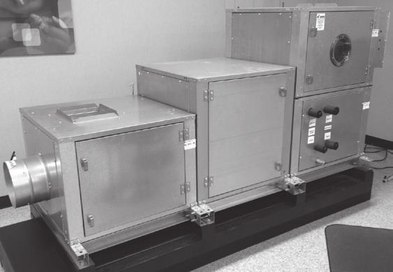
Modular Supply Make-Up Air Unit
 Modular Supply Make-Up Air Unit Model MSX Flexible Design Factory Assembled Heating Options Hot Water Steam Electric Cooling Options Evaporative Direct Expansion Chilled Water November 2009 Product Features
SPLIT-SYSTEM EVAPORATOR BLOWER DESCRIPTION FEATURES L4EU NOMINAL TONS
 036-21096-001 (0101) SPLIT-SYSTEM EVAPORATOR BLOWER L4EU240 20 NOMINAL TONS DESCRIPTION This 20 ton evaporator blower is designed with two distinct modules to provide maximum application flexibility. The
Brown University Revised August 3, 2012 Facilities Design & Construction Standards SECTION AIR HANDLING UNITS
 SECTION 23 70 00 AIR HANDLING UNITS PART 1. GENERAL 1.1 Section includes air-handling units to 15,000 cfm and accessories. 1.2 Related Sections 1 : A. Division 01 - Brown University Standard for Narragansett
CATALOG. MQL Modular Air-Handling Units
 CATALOG MQL Modular Air-Handling Units TABLE OF CONTENTS Product Overview...3 Features and Benefits...4 Application Considerations...5 Unit Configuration...6 Electric Heat...7 Coil and Filter Data...9
Submittal. RBVR Vertical Concealed Floor Mount FCU RBVR
 FCU RBVR 1.0 07 25 18 RBVR Vertical Concealed Floor Mount Unit Size 02 03 04 06 08 10 A 23 3/16 [589] 27 3/16 [691] 33 3/16 [843] 43 3/16 [1097] 45 3/16 [1148] 59 3/16 [1503] B 22 ¾ [578] 26 ¾ [679] 32
SECTION AIR HANDLING UNIT
 SECTION 15800 - AIR HANDLING UNIT PART 1 - GENERAL 1.01 RELATED DOCUMENTS A. Basic Requirements: Provisions of Section 15010, BASIC MECHANICAL REQUIREMENTS, and Section 15030, ELECTRICAL REQUIREMENTS FOR
SPLIT-SYSTEM EVAPORATOR BLOWERS K2EU060, K4EU090, K3EU120 & K1EU180 5 Thru 15 Nominal Tons DESCRIPTION ACCESSORIES FIELD INSTALLED
 (491) SPLIT-SYSTEM EVAPORATOR BLOWERS K2EU060, K4EU, K3EU & K1EU180 5 Thru 15 Nominal Tons DESCRIPTION These completely assembled units include a well-insulated cabinet, a DX cooling coil with copper tubes
1.1 This section applies to air handling units for HVAC Systems.
 AIR HANDLING UNITS GENERAL INFORMATION 1.1 This section applies to air handling units for HVAC Systems. DESIGN REQUIREMENTS 2.1 Design Criteria a. The decision to use modular central station air handling
engineering guide FN Fan-Coil Units High-Performance, Horizontal
 engineering guide FN Fan-Coil Units High-Performance, Horizontal Form 115.26-EG3 (909) TABLE OF CONTENTS High-Performance, Horizontal Fan-Coil Units Features and Benefits...3 Unit Arrangements...4 Construction
MHCCW Chilled Water Ceiling Concealed Without Electric Heat 2-Pipe Heat / Cool Fan Coil 18,000 BTUH
 MHCCW-06-00 Chilled Water Ceiling Concealed Without Electric Heat 2-Pipe Heat / Cool Fan Coil 18,000 BTUH Rev. 1.21 HVAC Guide Specifications Chilled or Hot Water Fan Coil 2-Pipe Nominal Size: 18,000 BTUH
A. Section includes Factory Packaged, Modular units, providing cooling and heating for air distribution systems.
 15855 AIR HANDLING UNITS SPECIFIER: CSI MasterFormat 2004 number: 237313 PART 1 GENERAL 1.1 SUMMARY A. Section includes Factory Packaged, Modular units, providing cooling and heating for air distribution
SKYPAK II, 3 Ton Series, gives you a
 SKYPAK II 3 ton Heating And Cooling self-contained Package SKYPAK II, 3 Ton Series, gives you a complete air-conditioning and heating system as an all in one package unit. Designed for convenient through-the-wall
MHCCW Chilled Water Ceiling Concealed With 5kW Electric Heat 2-Pipe Heat / Cool Fan Coil 30,000 BTUH
 MHCCW-10-05 Chilled Water Ceiling Concealed With 5kW Electric Heat 2-Pipe Heat / Cool Fan Coil 30,000 BTUH Rev. 1.21 HVAC Guide Specifications Chilled Water Fan Coil with Electric Heat 2-Pipe Nominal Size:
FLD = Furnished by Trane U.S. Inc. / Installed by Equipment Submittal Page 3 of 13
 Tag Data - Split System Air Conditioning Units (Large) (Qty: 6) Item Tag(s) Qty Description Model Number A1 20 ton vfd 6 6-25 Ton Unitary Split Systems ( SSC2 TTA24004H00-TWE240E404A TTA Air Condensing
SECTION AIR-COOLED SPLIT SYSTEM AIR CONDITIONING UNITS
 SECTION 23 62 13 - AIR-COOLED SPLIT SYSTEM AIR CONDITIONING UNITS PART 1 - GENERAL 1.1 RELATED DOCUMENTS: A. The Conditions of the Contract and applicable requirements of Division 1, "General Requirements",
KINGS COUNTY JAIL EXPANSION PHASE III COUNTY OF KINGS SECTION
 SECTION 237433, PART 1 - GENERAL 1.1 RELATED DOCUMENTS A. Drawings and general provisions of the Contract, including General and Supplementary Conditions and Division 01 Specification Sections, apply to
CHAMPION SPLIT-SYSTEM EVAPORATOR BLOWER DESCRIPTION FEATURES L2EU NOMINAL TONS
 550.23-TG5Y (893) CHAMPION SPLIT-SYSTEM EVAPORATOR BLOWER L2EU240 20 NOMINAL TONS DESCRIPTION This 20 ton evaporator blower is designed with two distinct modules to provide maximum application flexibility.
Guide Spec Summary. Option List. Date: 05/21/2001. EarthWise Modular Climate Changer Full Spec. Prepared by: Phone Number: Prepared for:
 Date: 05/21/2001 Time: 08:50:16 AM Job Name: EarthWise Modular Climate Changer Full Spec Location: Any Town, Earth Prepared by: Phone Number: Prepared for: Guide Spec Summary Option List SUBMITTALS Submittals
Catalog Destiny Indoor Air Handler. Models Horizontal Configuration. Vertical Configuration
 Destiny Indoor Air Handler Models 002 030 Catalog 580-8 Horizontal Configuration Vertical Configuration Table of Contents Introduction.... 2 Certification...2 Smoke Control and Management Systems...2 Features
A. American National Standards Institute (ANSI) : Establishes requirements applicable to certifying direct gas-fired heaters.
 : Establishes requirements applicable to certifying direct gas-fired heaters.") Section 15 _ Energy Recovery Air Handling System Part 1: GENERAL 1.1 Section Includes: A. Energy Recovery Air Handler B. Controls (most by Others) C. Equipment Schedule 1.2 Related Sections: A. Section
Section 15 _ Energy Recovery Air Handling System Part 1: GENERAL 1.1 Section Includes: A. Energy Recovery Air Handler B. Controls (most by Others) C. Equipment Schedule 1.2 Related Sections: A. Section
SKYPAK II, 3 Ton Series, gives you a
 SKYPAK II 3 ton Heating And Cooling self-contained Package SKYPAK II, 3 Ton Series, gives you a complete air-conditioning and heating system as an all in one package unit. Designed for convenient through-the-wall
Modular Heating & Ventilating Unit Model IGX-HV
 Modular Heating & Ventilating Unit Model IGX-HV Indirect Gas-Fired Heating Evaporative Chilled Water DX Cooling October 2008 Product Features Model IGX-HV Indirect Gas-Fired Heating and Ventilating Unit
Chilled Water DOAS Fan Powered Terminal Units
 Chilled Water DOAS Fan Powered Terminal Units CHILLED WATER DOAS FAN POWERED TERMINAL UNITS DOAS TERMINAL UNITS FEATURES AND BENEFITS MINIMUM VENTILATION CONTROL The DOAS unit provides the Designer, Owner
Construction Standards Page Exclusively published and distributed by Architectural Computer Services, Inc. (ARCOM) for the AIA
 for the AIA") Construction Standards Page 233423-1 Copyright 2009 by The American Institute of Architects (AIA) Exclusively published and distributed by Architectural Computer Services, Inc. (ARCOM) for the AIA Modified
Construction Standards Page 233423-1 Copyright 2009 by The American Institute of Architects (AIA) Exclusively published and distributed by Architectural Computer Services, Inc. (ARCOM) for the AIA Modified
UNIVERSITY SERVICES ANNEX James Madison University Harrisonburg, Virginia State Project Code: Architect s Project Number:
 SECTION 233423 - HVAC POWER VENTILATORS PART 1 - GENERAL 1.1 RELATED DOCUMENTS A. Provisions of the Contract and of the Contract Documents apply to this Section. 1.2 PERFORMANCE REQUIREMENTS A. Operating
VertiCool Aurora Engineering Guide
 Engineering Guide Effective August 2016 Air-Cooled, Water-Cooled and Water Source Heat Pump Contents Product Features... 3 Options... 4 Physical Data...5-6 Air-Cooled Performance Data (a) (b) (c)...7-8
TECHNICAL GUIDE SPLIT-SYSTEM AIR-COOLED EVAPORATOR BLOWER 25, 30, 40 & 50 TON LA300, LB360, 480 & 600 (50 Hz) PROVEN PERFORMANCE GENERAL FEATURING
 PROVEN PERFORMANCE GENERAL FEATURING") TECHNICAL GUIDE SPLIT-SYSTEM AIR-COOLED EVAPORATOR BLOWER 25, 30, 40 & 50 TON LA300, LB360, 480 & 600 (50 Hz) PROVEN PERFORMANCE GENERAL The LA/LB line is a flexible performer. LA300, LB360 & 480 can be
TECHNICAL GUIDE SPLIT-SYSTEM AIR-COOLED EVAPORATOR BLOWER 25, 30, 40 & 50 TON LA300, LB360, 480 & 600 (50 Hz) PROVEN PERFORMANCE GENERAL The LA/LB line is a flexible performer. LA300, LB360 & 480 can be
Technical Guide DESCRIPTION CHAMPION SPLIT-SYSTEM EVAPORATOR BLOWER L4EU240A 20 NOMINAL TONS (WORLD 50 HZ) FEATURES XTG-A-0307
 FEATURES XTG-A-0307") DESCRIPTION Technical Guide CHAMPION SPLIT-SYSTEM EVAPORATOR BLOWER L4EU240A 20 NOMINAL TONS (WORLD 50 HZ) This 20 ton evaporator blower is designed with two distinct modules to provide maximum application
DESCRIPTION Technical Guide CHAMPION SPLIT-SYSTEM EVAPORATOR BLOWER L4EU240A 20 NOMINAL TONS (WORLD 50 HZ) This 20 ton evaporator blower is designed with two distinct modules to provide maximum application
SECTION FAN COIL UNITS
 PART 1 GENERAL 1.1 RELATED DOCUMENTS A. Drawings and general provisions of the Contract, including General and Supplementary Conditions and Specification Sections, apply to this Section. B. Related Sections:
UNIVERSITY OF MISSOURI Central Station Air-Handling Units March
 GENERAL: 1. This section provides criteria for the design and installation of air handling units. DESIGN GUIDELINES: Design General 1. Location 1.1. For new construction, and existing buildings where possible,
VariCool VAV Engineering Guide
 Engineering Guide Effective September 2017 Water-Cooled and Chilled Water, Variable Air Volume Contents Product Features... 3 UNIT FEATURES... 3 Product Features... 4 Marvel Plus Microprocessor Control
MHNCCW (4-Pipe) Chilled/Hot Water Ceiling Concealed 208/230V 4-Pipe Heating & Cooling Fan Coil 12,000 BTUH
 Chilled/Hot Water Ceiling Concealed 208/230V 4-Pipe Heating & Cooling Fan Coil 12,000 BTUH") MHNCCW-04-01 (4-Pipe) Chilled/Hot Water Ceiling Concealed 208/230V 4-Pipe Heating & Cooling Fan Coil 12,000 BTUH Rev. 1.2 HVAC Guide Specifications Chilled and Hot Water Fan Coil 4-Pipe Nominal Size: 12,000
MHNCCW-04-01 (4-Pipe) Chilled/Hot Water Ceiling Concealed 208/230V 4-Pipe Heating & Cooling Fan Coil 12,000 BTUH Rev. 1.2 HVAC Guide Specifications Chilled and Hot Water Fan Coil 4-Pipe Nominal Size: 12,000
C13-Series Engineering Guide
 Engineering Guide Effective January 2018 Horizontal Air-Cooled, Water-Cooled, Chilled Water and Heat Pump Contents Product Features............................... 3 Product Options................................
Catalog C: McQuay Horizontal Concealed Fan Coil Unit
 Catalog C: 700-1 McQuay Horizontal Concealed Fan Coil Unit Model THC Sizes 200 Through 1200 CFM McQuay THC Horizontal Concealed Fan Coil Nomenclature F THC 1 H02 Fan-coil Type of Unit THC = Horizontal
MHNCCX DX with Hot Water Heat Ceiling Concealed 4-Pipe Heat / Cool Fan Coil 12,000-36,000 BTUH
 MHNCCX DX with Hot Water Heat Ceiling Concealed 4-Pipe Heat / Cool Fan Coil 12,000-36,000 BTUH 318 MHNCCX NOMENCLATURE BREAKDOWN 4-Pipe Heat/Cool Ceiling Concealed Fan Coil MHNCCW- XX - XX Ceiling Concealed
K*ES120 DESCRIPTION TECHNICAL GUIDE SPLIT-SYSTEM EVAPORATOR BLOWERS 10 NOMINAL TONS EER 8.5 ACCESSORIES FIELD INSTALLED TABLE 1: ARI RATINGS*
 TECHNICAL GUIDE SPLIT-SYSTEM EVAPORATOR BLOWERS K*ES120 10 NOMINAL TONS EER 8.5 DESCRIPTION These completely assembled dual circuit evaporator blower units include a well-insulated cabinet, a DX cooling
Product Specifications. Vertical Floor Consoles By First Co.
 NOW WITH 18 GAUGE CABINET AND FACTORY INSTALLED SERVICE SWITCH Product Specifications VFB Series VSB Series VCB Series Vertical Console Fan Coils 300-00 CFM Vertical Floor Consoles By First Co. VFB Series
AIR HANDLERS. Central Station (CS3) Roof Mounted (RT) (Modular AL Frame AHU)
 Roof Mounted (RT) (Modular AL Frame AHU)") AIR HANDLERS Central Station (CS3) (Modular AL Frame AHU) Roof Mounted (RT) CONTENTS 1. CS3 Modular Aluminium Frame AHU : Unit Types 2. Casing Structure 3. Blowers and Drives 4. Coils 5. Options and Accessory
AIR HANDLERS Central Station (CS3) (Modular AL Frame AHU) Roof Mounted (RT) CONTENTS 1. CS3 Modular Aluminium Frame AHU : Unit Types 2. Casing Structure 3. Blowers and Drives 4. Coils 5. Options and Accessory
Technical Guide SUNLINE 2000 DESCRIPTION ACCESSORIES FIELD INSTALLED SPLIT-SYSTEM EVAPORATOR BLOWER K4EU NOMINAL TONS (WORLD 50 HZ)
") Technical Guide SUNLINE 2000 SPLIT-SYSTEM EVAPORATOR BLOWER K4EU180 15 NOMINAL TONS (WORLD 50 HZ) DESCRIPTION These completely assembled units include a well-insulated cabinet, a DX cooling coil with copper
Technical Guide SUNLINE 2000 SPLIT-SYSTEM EVAPORATOR BLOWER K4EU180 15 NOMINAL TONS (WORLD 50 HZ) DESCRIPTION These completely assembled units include a well-insulated cabinet, a DX cooling coil with copper
XeteX, Inc. All Rights Reserved.
 Model DXH Custom, packaged, roof mounted or indoor mounted unit with cooling (DX or Chilled Water) and an air-to-air aluminum flat plate exchanger designed to provide pre-cooling and reheat. The DXH is
VERTICAL FAN COIL UNITS
 VERTICAL FAN COIL UNITS VERTICAL FAN COIL UNITS Model: CT & TCE 2 - Pipe 350 cfm to 1200 cfm capacity 4-row water coil 120v or 24v controls Electric heating coil (TCE Model) Fresh air connection from remote
Large Capacity Fan Coil Units Catalog Belt-Drive and Direct-Drive Cabinet and Hideaway Models
 Large Capacity Fan Coil Units Catalog 735-12 Belt-Drive and Direct-Drive Cabinet and Hideaway Models Table of Contents Agency Listing and Nomenclature... 3 Overview....................................
SECTION PACKAGED ROOFTOP AIR CONDITIONING UNITS
 SECTION 15732 - PACKAGED ROOFTOP AIR CONDITIONING UNITS PART 1 - GENERAL 1.1 SECTION INCLUDES A. Package roof top unit. B. Heat exchanger. C. Refrigeration components. D. Unit operating controls. E. Roof
Advance Release September 2009
 Vertical Air Cooled DSV Series R 410A Model DSV096 DSV120 DSV144 DSV180 Nominal Cooling (Tons) 8 10 12 15 Refrigerant R 410A R 410A R 410A R 410A Cooling Performance Gross Cooling Capacity(Btu/h) 95,000*
DENVER PUBLIC SCHOOLS DESIGN AND CONSTRUCTION STANDARDS This Standard is for guidance only. SECTION EXHAUST FANS
 PART 0 A/E INSTRUCTIONS 0.01 DESIGN REQUIREMENTS A. Placement within a mechanical room is required for all major mechanical equipment. Only small units may be roof-mounted, and shall be made as inconspicuous
EMBASSY SERIES SINGLE PACKAGE AIR CONDITIONERS (WATER-COOLED) C2ED060, 090, 120 & 180 5, 7-1/2, 10 & 15 Nominal Tons
 C2ED060, 090, 120 & 180 5, 7-1/2, 10 & 15 Nominal Tons") 560.20-TG1Y (388) EMBASSY SERIES SINGLE PACKAGE AIR CONDITIONERS (WATER-COOLED) C2ED060, 090, 120 & 180 5, 7-1/2, 10 & 15 Nominal Tons Each circuit includes a fully hermetic compressor with a crankcase
560.20-TG1Y (388) EMBASSY SERIES SINGLE PACKAGE AIR CONDITIONERS (WATER-COOLED) C2ED060, 090, 120 & 180 5, 7-1/2, 10 & 15 Nominal Tons Each circuit includes a fully hermetic compressor with a crankcase
SPLIT-SYSTEM HEAT PUMPS 50 AND 60 HZ DESCRIPTION
 SPLIT-SYSTEM HEAT PUMPS 50 AND 60 HZ E3FB090/E1FB120/F3EH090 & 120 7-1/2 & 10 NOMINAL TONS (60 HZ) 7 & 9 NOMINAL TONS (50 HZ) (9.0-9.2 EER) 208/230/460 VOLT ONLY 208/230 VOLT ONLY DESCRIPTION YORK has
ENGINEERING GUIDE. Water-Cooled Self-Contained Units C-Series, Vertical
 ENGINEERING GUIDE Water-Cooled Self-Contained Units C-Series, Vertical TABLE OF CONTENTS Introduction...2 Product Overview...3 Nomenclature...4 General Data...5 Cooling Performance Data....6 Evaporator
KIC Air Curtains. Technical Guide
 TGKIC-3 KIC Air Curtains Technical Guide AIR PERFORMANCE AIR MOVEMENT AND CONTROL ASSOCIATION INTERNATIONAL, INC. King certifies that the air curtains shown herein are licensed to bear the AMCA seal. The
Stanford University Facilities Design Guidelines SECTION DECENTRALIZED UNITARY HVAC EQUIPMENT
 SECTION 23 81 00 DECENTRALIZED UNITARY HVAC EQUIPMENT PART 1 - GENERAL 1.1 SUMMARY A. Section includes packaged roof top unit, unit controls, remote panel, roof mounting curb and base, maintenance service,
DARTMOUTH COLLEGE DESIGN January 3, 2012 & CONSTRUCTION GUIDELINES
 SECTION 15856 MODULAR AIR HANDLING UNITS PART 1 DESIGN DIRECTIVES 1.1 QUALITY ASSURANCE A. NFPA Compliance: Modular air handling units and components shall be designed, fabricated, and installed in compliance
TECHNICAL GUIDE GENERAL SPECIFICATIONS COMMERCIAL SPLIT-SYSTEM COOLING UNITS FOUR PIPE SYSTEM OUTDOOR UNIT: INDOOR UNIT:
 GENERAL SPECIFICATIONS OUTDOOR UNIT: TECHNICAL GUIDE COMMERCIAL SPLIT-SYSTEM COOLING UNITS FOUR PIPE SYSTEM MODELS HB 180 & HB 240 MODELS LB 180 & LB 240 15 & 20 NOMINAL TONS 9.7 EER Two independent refrigerant
Cabinet Unit Heaters Steam / Hot Water
 11-160.4 February, 2005 Cabinet Unit Heaters Steam / Hot Water Model C MODEL IDENTIFICATION Table of Contents I. Model Identification... 3 Page Il. IIl. III. IV. Design Benefits A. Features and Benefits...
AIR HANDLING UNITS Vibration Isolation Air Filtration Equipment Ductwork.
 SECTION 15855 AIR HANDLING UNITS PART 1 GENERAL 1.01 SUMMARY A. Related Sections: 1. 15240 - Vibration Isolation. 2. 15885 - Air Filtration Equipment. 3. 15890 - Ductwork. 1.02 REFERENCES A. Air Moving
SECTION CONVECTION HEATING AND COOLING UNITS
 PART 1 GENERAL 1.01 SECTION INCLUDES A. Baseboard radiation. B. Finned tube radiation. C. Convectors. D. Unit heaters. E. Cabinet unit heaters. F. Fan-coil units. G. Unit ventilators. H. Blower-coil units.
CFFWA4P-16-1-U Chilled/Hot Water Universal Mount Fan Coil (4-Pipe) 4-Pipe Heat / Cool Fan Coil 48,000 BTUH
 4-Pipe Heat / Cool Fan Coil 48,000 BTUH") CFFWA4P-16-1-U Chilled/Hot Water Universal Mount Fan Coil (4-Pipe) 4-Pipe Heat / Cool Fan Coil 48,000 BTUH Rev. 1.3 HVAC Guide Specifications Chilled and Hot Water Universal Mount Fan Coil 4-Pipe Nominal
CFFWA4P-16-1-U Chilled/Hot Water Universal Mount Fan Coil (4-Pipe) 4-Pipe Heat / Cool Fan Coil 48,000 BTUH Rev. 1.3 HVAC Guide Specifications Chilled and Hot Water Universal Mount Fan Coil 4-Pipe Nominal
CFFWA4P-12-1-U Chilled/Hot Water Universal Mount Fan Coil (4-Pipe) 4-Pipe Heat / Cool Fan Coil 36,000 BTUH
 4-Pipe Heat / Cool Fan Coil 36,000 BTUH") CFFWA4P-12-1-U Chilled/Hot Water Universal Mount Fan Coil (4-Pipe) 4-Pipe Heat / Cool Fan Coil 36,000 BTUH Rev. 1.3 HVAC Guide Specifications Chilled and Hot Water Universal Mount Fan Coil 4-Pipe Nominal
CFFWA4P-12-1-U Chilled/Hot Water Universal Mount Fan Coil (4-Pipe) 4-Pipe Heat / Cool Fan Coil 36,000 BTUH Rev. 1.3 HVAC Guide Specifications Chilled and Hot Water Universal Mount Fan Coil 4-Pipe Nominal
SPLIT-SYSTEM EVAPORATOR BLOWER DESCRIPTION ACCESSORIES - FIELD INSTALLED. K5EU090 and K4EU Hz 7.5 and 10 NOMINAL TONS SUNLINE 2000 (WORLD 50 HZ)
") (994) SPLIT-SYSTEM EVAPORATOR BLOWER K5EU090 and K4EU120 50 Hz 7.5 and 10 NOMINAL TONS SUNLINE 2000 (WORLD 50 HZ) DESCRIPTION These completely assembled units include a well-insulated cabinet, a DX coil
(994) SPLIT-SYSTEM EVAPORATOR BLOWER K5EU090 and K4EU120 50 Hz 7.5 and 10 NOMINAL TONS SUNLINE 2000 (WORLD 50 HZ) DESCRIPTION These completely assembled units include a well-insulated cabinet, a DX coil
Vertical V*B Series Fan Coil Technical Catalog
 Vertical V*B Series Fan Coil Technical Catalog Vertical Hideaway (VCB) 200 CFM to 1200 CFM The Vertical Hideaway (VCB) fan coil unit is designed for concealed applications. The coil section is lined with
CFFWA4P-08-1-U Chilled/Hot Water Universal Mount Fan Coil (4-Pipe) 4-Pipe Heat / Cool Fan Coil 24,000 BTUH
 4-Pipe Heat / Cool Fan Coil 24,000 BTUH") CFFWA4P-08-1-U Chilled/Hot Water Universal Mount Fan Coil (4-Pipe) 4-Pipe Heat / Cool Fan Coil 24,000 BTUH Rev. 1.3 HVAC Guide Specifications Chilled and Hot Water Universal Mount Fan Coil 4-Pipe Nominal
CFFWA4P-08-1-U Chilled/Hot Water Universal Mount Fan Coil (4-Pipe) 4-Pipe Heat / Cool Fan Coil 24,000 BTUH Rev. 1.3 HVAC Guide Specifications Chilled and Hot Water Universal Mount Fan Coil 4-Pipe Nominal
Guide Spec Summary. Option List. Date: 05/21/2001. EarthWise VAV Terminal Units Full Spec. Prepared by: Phone Number: Prepared for:
 Date: 05/21/2001 Time: 02:57:44 PM Job Name: EarthWise VAV Terminal Units Full Spec Location: AnyTown, Earth Prepared by: Phone Number: Prepared for: Guide Spec Summary Option List SINGLE & DUAL DUCT UNIT
Internal ridged board 1" x 1.5 foil face installation shall be installed on roof, walls and base of casing.
 A-D WITH MPU SPECIFICATION WRITTEN SPECIFICATION Description A Modular Packaged Heating, Cooling and ventilating unit(s), as indicated on the drawings shall be furnished. Direct Fired Gas Unit(s) shall
DSV Model Air Cooled Self Contained Indoor Packaged Units 3-5 Tons Preliminary Application Data
 DSV Model Air Cooled Self Contained Indoor Packaged Units 3-5 Tons Preliminary Application Data July 28, 2008 Page 1 1 of 3 PROJECT: TAG: Gross Cooling Capacity [Btuh]: 37,800* Design CFM: 1,200 Seasonal
VERTICAL STACK INNKEEPER GUIDE SPECIFICATION CGC Hybrid Heat Pump System
 VERTICAL STACK INNKEEPER GUIDE SPECIFICATION CGC Hybrid Heat Pump System PART 1 SYSTEM DESCRIPTION 1.1 The HVAC system is based on the CGC HYBRID Hydronic Heat Pump System. 1.2 The system will automatically
TECHNICAL GUIDE SPLIT-SYSTEM AIR-COOLED EVAPORATOR BLOWER 25, 30, 40 & 50 TON LA300, LB360, 480 & 600 PROVEN PERFORMANCE GENERAL FEATURING
 TECHNICAL GUIDE SPLIT-SYSTEM AIR-COOLED EVAPORATOR BLOWER 25, 30, 40 & 50 TON LA300, LB360, 480 & 600 PROVEN PERFORMANCE GENERAL The LA/LB line is a flexible performer. LA300, LB360 & 480 canbepositionedinupto12differentpositionsandsuspended
SECTION CUSTOM INDOOR CENTRAL-STATION AIR-HANDLING UNITS For large systems, 50,000 cfm or more.
 Page 237323-1 SECTION 237323 - For large systems, 50,000 cfm or more. PART 1 - GENERAL 1.1 RELATED DOCUMENTS A. Drawings and general provisions of the Contract, including General and Supplementary Conditions
VertiCool CLASSIC. Engineering Guide. Effective March Air-Cooled, Water-Cooled, Chilled Water and Water Source Heat Pump
 VertiCool CLASSIC Engineering Guide Effective March 2018 Air-Cooled, Water-Cooled, Chilled Water and Water Source Heat Pump Contents Product Features... 3 UNIT FEATURES... 3 OPTIONS:... 3 Physical Data...
Direct Fired Heater Model AD Specification
 Direct Fired Heater Model AD Specification Description A Direct-fired gas heating and ventilating unit(s), as indicated on the drawings shall be furnished. Unit(s) shall be tested in accordance with ANSI
DSH Model Air Cooled Self Contained Indoor Packaged Units 2-5 Tons Preliminary Application Data
 DSH Model Air Cooled Self Contained Indoor Packaged Units 2-5 Tons Preliminary Application Data July 28, 2008 Page 1 1 of 3 PROJECT: TAG: Gross Cooling Capacity [Btuh]: 25,240* Design CFM: 800 Seasonal
UNIVERSITY OF ROCHESTER DESIGN STANDARDS NOVEMBER 1, 2013
 SECTION 15800 - AIR HANDLING EQUIPMENT 1.1 GENERAL A. All air handlers installed shall conform to the University of Rochester specification Guideline for Semi-Custom and Pre-Engineered Air Handling Units.
KAP Horizontal Product Coolers
 PRODUCT DATA & INSTALLATION Bulletin K80-KAP-PDI-6 Part # 1097718 PRODUCT SUPPORT web: k-rp.com/kap email: ahu@k-rp.com call: 1-844-893-3222 x527 scan: KAP Horizontal Product Coolers Air Defrost for Applications
SeasonMaker ThinLine Fan-coil Units
 Catalog C: 720-12 SeasonMaker ThinLine Fan-coil Units Type TSH & TSC Horizontal Design TSS, TPF, TSF & TSB Vertical Design C L I S T E D Ratings Certified by the Air Conditioning & Refrigeration Institute
CATALOG. SKYPAK Self-Contained Heating/Cooling Units
 CATALOG SKYPAK Self-Contained Heating/Cooling Units FORM SK145.00-EG6 (1211) TABLE OF CONTENTS SKYPAK Self-Contained Heating/Cooling Units Introduction...3 Product Overview...3 Nomenclature...4 SKYPAK
TYPICAL CPA SPECIFICATIONS
 TYPICAL CPA SPECIFICATIONS 4/10/2017 UNIT CONSTRUCTION: Casing: The exterior casing of the unit shall be constructed of 18-gauge, G235 galvanized steel (optional stainless steel or aluminum), unpainted.
SeasonMaker ThinLine Fan-coil Units
 Catalog C: 720-12 SeasonMaker ThinLine Fan-coil Units Type TSH & TSC Horizontal Design TSS, TPF, TSF & TSB Vertical Design C L I S T E D Ratings Certified by the Air Conditioning & Refrigeration Institute
CoolSpot Engineering Guide
 Engineering Guide Effective December 2017 Air-Cooled, Water-Cooled, Chilled Water or Magna Cool Precision Cooling Package Contents Contents....................................................... 2 Product
Warm. IFR Indirect Fired Gas Heating Systems. Applied Air. Keeps You
 TGIFR IFR Indirect Fired Gas Heating Systems Technical Guide for: Outdoor Rooftop Mounted Units To 46,000 CFM And 4,000 MBH Output Applied Air Keeps You Warm Indirect Fired Heating Systems Technical Guide
Technical Guide DESCRIPTION ACCESSORIES FIELD INSTALLED SPLIT-SYSTEM EVAPORATOR BLOWERS. 7-1/2 and 10 NOMINAL TONS LA090 & LA120 SUPPLY AIR PLENUMS
 Technical Guide SPLIT-SYSTEM EVAPORATOR BLOWERS 7-1/2 and 10 NOMINAL TONS LA090 & LA120 DESCRIPTION These completely assembled units include a well-insulated cabinet, a DX cooling coil with copper tubes
Multi-position, Upflow, Horizontal Left, or Horizontal Right, Modular Air Handlers
 Multi-position, Upflow, Horizontal Left, or Horizontal Right, Modular Air Handlers 60 HZ Convertible Air Handlers Model: Series 2 Air Handlers 1.5-3 ton Standard Coil Black Epoxy Coil GAF2A0A18S11SE GAF2A0A18S11EE
High Plume Blowers Suggested Specification Section (Master Format 1996) Suggested Specification Section (Master Format 2004)
 Suggested Specification Section (Master Format 2004)") High Plume Blowers Suggested Specification Section 15500 (Master Format 1996) Suggested Specification Section 23 38 16 (Master Format 2004) PART 1 GENERAL 1.01 WORK INCLUDED High Plume Laboratory Exhaust
High Plume Blowers Suggested Specification Section 15500 (Master Format 1996) Suggested Specification Section 23 38 16 (Master Format 2004) PART 1 GENERAL 1.01 WORK INCLUDED High Plume Laboratory Exhaust
A. Product Data: Include rated capacities, operating characteristics, furnished specialties, and accessories.
 Page 238219-1 SECTION 238219 - PART 1 - GENERAL 1.1 RELATED DOCUMENTS A. Drawings and general provisions of the Contract, including General and Supplementary Conditions and Division 01 Specification Sections,
A. General: Refer to paragraph entitled "SUBMITTAL" in Section Include the following data:
 SECTION 15860 - FANS PART 1 - GENERAL 1.01 RELATED DOCUMENT A. Basic Requirements: Provisions of Section 15010, BASIC MECHANICAL REQUIREMENTS, and Section 15030, ELECTRICAL REQUIREMENTS FOR MECHANICAL
Submittal Data 558F SINGLE-PACKAGE ELECTRIC HEATING/ ELECTRIC COOLING UNITS NOMINAL TONS DESCRIPTION FEATURES
 180-300 INGLE-PACKAGE ELECTRIC HEATING/ ELECTRIC COOLING UNIT 15-25 NOMINAL TON ubmittal Data DECRIPTION The units are one -piece electric cooling/optional electric heating units, prewired and precharged.
Construction Standards Page
 Construction Standards Page 236313-1 SECTION 236313 - PART 1 - GENERAL 1.1 RELATED DOCUMENTS A. Drawings and general provisions of the Contract, including General and Supplementary Conditions and Division
TECHNICAL GUIDE DESCRIPTION EA090/FA090 SPLIT-SYSTEM HEAT PUMPS OUTDOOR UNIT INDOOR UNIT
 TECHNICAL GUIDE SPLIT-SYSTEM HEAT PUMPS EA090/FA090 DESCRIPTION YORK has combined the latest concepts in modern technology with time-proven quality standards to design a split-system heat pump to meet
VERTICOOL TECHNICAL DATA MANUAL. Vertical Air/Water Cooled 3-25 Tons
 491 East Princess Street York, PA 17403 877-905-1111 717-843-4311 Fax: 717-854-4462 uca@unitedcoolair.com www.unitedcoolair.com VERTICOOL TECHNICAL DATA MANUAL Vertical Air/Water Cooled 3-25 Tons UNITED
Water-Cooled Self-Contained Units
 CATALOG FORM SK145.15-EG1 (1017) Water-Cooled Self-Contained Units C-Series, Vertical Nomenclature WATER-COOLED SELF-CONTAINED UNIT 1, 2 3 4, 5, 6 7 8 9 10 11 12 13 14 15 16 17 CS V 180 B 2 M 1 V A A A
TECHNICAL GUIDE DESCRIPTION SPLIT-SYSTEM AIR-COOLED CONDENSING UNITS MODELS: HF-07 FEATURES B-0703
 TECHNICAL GUIDE SPLIT-SYSTEM AIR-COOLED CONDENSING UNITS MODELS: HF-07 DESCRIPTION These Sunline 2000 units are completely assembled, piped and wired at the factory to provide one-piece shipment and rigging.
C. ASME Compliance: Fabricate and label water chiller heat exchangers to comply with ASME Boiler and Pressure Vessel Code: Section VIII, Division 1.
 SECTION 236426 - ROTARY-SCREW WATER CHILLERS PART 1 - GENERAL 1.1 SUMMARY A. This Section includes packaged, water cooled or air cooled as scheduled, electric-motor-driven, rotary-screw water chillers
Direct Gas-Fired Make-Up Air
 Direct Gas-Fired Make-Up Air Model TSU Heavy Duty, High Airflow Applications Manufacturing and Industrial Facilities Up to 64,000 cfm August 2012 Products Model TSU Direct Gas-Fired Make-Up Air Unit The
Large Capacity Fan Coil Units Belt and Direct Drive Cabinet and Hideaway
 Catalog C: 735-7 Large Capacity Fan Coil Units Belt and Direct Drive Cabinet and Hideaway Direct Drive CUL Listed McQuay Large Capacity Fan Coil Units Page 2 / Catalog 735 Direct drive hideaway unit The