Plant Application Guide
|
|
|
- Crystal Floyd
- 6 years ago
- Views:
Transcription
 1996-2016 THE BOARD OF TRUSTEES OF THE UNIVERSITY OF ILLI- NOIS AND THE REGENTS OF THE UNIVERSITY OF CALIFORNIA THROUGH THE ERNEST ORLANDO LAWRENCE")
1 EnergyPlus Version 8.5 Documentation Plant Application Guide U.S. Department of Energy March 31, 2016 COPYRIGHT (c) THE BOARD OF TRUSTEES OF THE UNIVERSITY OF ILLI- NOIS AND THE REGENTS OF THE UNIVERSITY OF CALIFORNIA THROUGH THE ERNEST ORLANDO LAWRENCE BERKELEY NATIONAL LABORATORY. ALL RIGHTS RESERVED. NO PART OF THIS MATERIAL MAY BE REPRODUCED OR TRANSMITTED IN ANY FORM OR BY ANY MEANS WITHOUT THE PRIOR WRITTEN PERMISSION OF THE UNIVERSITY OF ILLINOIS OR THE ERNEST ORLANDO LAWRENCE BERKELEY NATIONAL LABORATORY. ENERGYPLUS IS A TRADEMARK OF THE US DEPARTMENT OF ENERGY.
2 Contents 1 Introduction Organization Scope 4 3 EnergyPlus Nomenclature 6 4 Generating an EnergyPlus Line Diagram Example for EnergyPlus Line Diagram Generation Inputting the system into the IDF file 16 6 Example System 1: Chiller and Condenser Loops Chilled water (CW) loop Flowcharts for the CW Loop Input Process Flowcharts for CW Loop Controls Condenser Loop Flowcharts for the Condenser Loop Input Process Flowcharts for Condenser Loop Controls Example System 2: Thermal Energy Storage Primary Cooling Loop (CoolSysPrimary) - Chiller Flowcharts for the Primary Cooling Loop Input Process Flowcharts for Primary Cooling Loop Controls Condenser Loop (Condenser Loop) - Cooling Tower Flowcharts for the Condenser Loop Input Process Flowcharts for Condenser Loop Controls Heating Loop (HeatSys1) - Boiler Flowcharts for the Heating Loop Input Process Flowcharts for Heating Loop Controls Example System 3: Primary/Secondary Pumping Primary Chilled Water Loop Chiller(s) and purchased cooling Flowcharts for the Primary Chilled Water Loop Input Process Flowcharts for Primary Chilled Water Loop Controls Secondary Chilled Water Loop Plate Heat Exchanger
3 CONTENTS Flowcharts for the Secondary Chilled Water Loop Input Process Flowcharts for secondary chilled water loop Controls Primary/Secondary Pumping Condenser Loop - Cooling Tower Flowcharts for the Condenser Loop Input Process Flowcharts for Condenser Loop Controls References 96
4 Chapter 1 Introduction This document provides an in-depth look at plant modeling in EnergyPlus. Plant refers to the subset of HVAC that involves hydronic equipment for heating, cooling, and service water heating (or domestic hot water). This guide serves as an aid to help model plant systems in EnergyPlus simulations. It is intended to augment the Input Output Reference, which describes the syntax and the details of individual input objects. This guide will discuss how the different objects can be used to construct a plant loop that can service a building load. 1.1 Organization This document begins with some general information to introduce users to the syntax used in EnergyPlus as well as this guide. Then some basic conversion methods needed to take a real system and format it to simplify the input process are provided. The bulk of this Application Guide is devoted to modeling example systems. The example systems are intended to demonstrate the input process for various types of plant systems, such as systems that use thermal energy storage tanks and those that have a primary/secondary pumping configurations. The example systems are defined by breaking the system into its constituent loops. The loops are then separated into supply and demand sides. These half-loops are then defined by branches, connectors, and components. The controls for each loop are set after the loop has been completed. Figures and flowcharts are used to display the definition process. The flow charts should be read from top to bottom and each branched level should be read from left to right. The Object Class Names and Object Names used in the flow charts match those used in the input file provided for the example. One thing that is not specified in the flow charts or figures is the node names used. The various object class names and object names used in the examples refer to the entries in the example input files. 4
5 Chapter 2 Scope The scope of modeling plant loops in EnergyPlus is limited depending on the application. For example, there is no provision to model nested loops, and multiple splitter-mixer pairs in a single loop which are often used in large scale systems. Thus, it has to be realized that modeling large scale district loops may be challenging in EnergyPlus. One way to model such systems is to make some assumptions to condense some arrangements of components that cannot be modeled in EnergyPlus. This approach may not work because the arrangements could be very important to the system. Figure 2.1 shows a central plant chilled water system for the University of California, Riverside (Hyman and Little, 2004). This system contains a total of eight splitter-mixer pairs, four on the supply side, and four on the demand side. We could make some assumptions to simplify the system. For example we can use a single chiller instead of the array of five chillers, this could work if we size and control the chiller properly, but the concept of scheduling the different chillers to operate at different times of the day to improve efficiency will be lost. Hence, it should be noted that while simplifications can provide a general overview of how the system will operate, they may defeat the original purpose of the complex design. Therefore, this guide will only discuss building plant systems which are less complicated. 5


6 6 CHAPTER 2. SCOPE Figure 2.1: Central plant chilled water schematic for the University of California, Riverside (recreated from Hyman and Little, 2004)
7 Chapter 3 EnergyPlus Nomenclature The following is a list of terms that are used in this guide. A simple description of each of the terms is provided. More detailed descriptions can be obtained from the EnergyPlus Input Output Reference. Some keywords are provided to assist with the search for these terms in the Input Output Reference guide. Loops Loops are high-level construction objects in EnergyPlus. Loops are paths through which the working fluid is circulated in order to satisfy a cooling or heating load. An HVAC system may consist of a zone, plant loop, and a condenser loop. Loops are constructed by using branches. (Keywords: PlantLoop). Note: Although Energy- Plus has separate object classes for CondenserLoops and PlantLoops, the difference between them is very trivial; therefore all the condenser loops in this guide will be modeled by a PlantLoop object. Supply side half-loop This is the half loop that contains components (such as Boilers and chillers) which treat the working fluid to supply a working fluid state to the demand components. Demand side half-loop This is the half loop that contains components (such as cooling coils and heating coils which use the working fluid to satisfy a load. Branches Branches are mid-level construction objects in EnergyPlus. Branches are the segments used to construct the loops. They are constructed by using nodes and a series of components. Every branch must have at least one component. Branches will be denoted by using blue colored lines in the EnergyPlus schematics. (Keyword: Branch). Branchlists Branchlists list all the branches on one side of a loop. Branchlist). (Keyword: Bypass Branch A bypass branch is used to bypass the core operating components, it ensures that when the operating components are not required, the working fluid can be circulated through the bypass pipe instead of component. Note: Only one bypass per half loop is required. 7
8 8 CHAPTER 3. ENERGYPLUS NOMENCLATURE Connectors Connectors are mid-level loop construction objects that are used to connect the various branches in the loops. There are two kinds of connectors: splitter which split the flow into two or more branches, and mixers which mix the flow from two or more branches. A connector pair consists of a splitter and a mixer. A maximum of one connector pair is allowed on each half loop. Connectors will be denoted by using green colored lines in the EnergyPlus schematics used in this guide. (Keywords: Connector:Mixer, Connector:Splitter). Connectorlists Connectorlists list all the connectors on one side of a loop. (Keyword: Connectorlist). Components Components are the low-level construction objects in EnergyPlus. Physical objects that are present in the loop are generally called components. Components such as a chiller, cooling tower, and a circulation pump can be considered as the operating/active components. Pipes and ducts can be considered as passive or supporting components. (Keywords: Chiller:Electric, Pipe:Adiabatic, and many others). Nodes Nodes define the starting and ending points of components and branches. Nodelists Nodelists can be used to list a set of nodes in the loop. These nodelists can then be used for a variety of purposes. For example, a setpoint can be assigned to multiple nodes by referring to a particular nodelist. (Keyword: Nodelist). Set-point Setpoints are control conditions imposed on node(s) that are monitored by the SetpointManager to control the system. (Keyword: SetpointManager:Scheduled, and others). Plant equipment operation scheme This object details the mechanism required to control the operation of the plant loop, as well as the availability of the plant equipment under various conditions. (Keyword: PlantEquipmentOperation:CoolingLoad, and others). Schedule Schedules allow the user to influence the scheduling of many operational parameters in the loop. For example, a schedule can determine the time period of a simulation, or instruct the load profile object of a plant to import data from a certain external file, among other actions. (Keywords: Schedule:Compact, Schedule:file). Load Profile A load profile object is used to simulate a demand profile. This object can be used when the load profile of a building is already known. (Keyword: LoadProfile:Plant). Note: This object does not allow feedback from the plant conditions to the air system or the zones. However, this object is a great tool for plant-only development and debugging.
9 Chapter 4 Generating an EnergyPlus Line Diagram The following list of steps will outline the process for converting an engineering line diagram into an EnergyPlus line diagram. Throughout the process, the components in the systems should be identified and named properly. It is easier to input the system if a list of components and their names is available. 1. Obtain an engineering line diagram for the system. 2. Identify all the loops in the system. Some systems may be very complex, but an effort should be made to separate the system into its constituent plant loops. A system may have multiple plant loops. Therefore, proper documentation of the loops and their components should be a priority. 3. Identify the demand side and supply side of the individual loops. EnergyPlus expects the demand side loop and supply side loop to be entered separately. Some examples of simple plant loops are: a hot water heater (supply component) connected to a heating coil (demand component), a chiller (supply component) connected to a cooling coil (demand component) or a cooling tower (supply component) connected to a water cooled chiller (demand component). These loops may have multiple supply components and multiple demand components. A chiller may also be a supply or demand component depending on the loop. 4. Identify the components in the system. All the operating/active components, such as chillers, pumps, cooling towers, thermal energy storage tanks, heating and cooling coils, and other components should be identified and named properly. It should be noted that even though EnergyPlus has objects for modeling valves, they are not often used. Instead the flow through a component is regulated by using schedules, plant equipment operation schemes and set points. Passive components such as inlet and outlet pipes for each side of the loop should also be identified, as they will help in modeling the loop connectors. 5. Identify all the nodes in the system. Nodes are necessary to connect the different components in the system. Nodes define the starting and ending points of branches as well as intermediate nodes on multi-component branches. A good method to pin-point nodes on the line diagram would be to put a node on either side of an active or passive component. Note: If the outlet of one component does not feed into a splitter or a mixer, then the outlet node will be the same as the inlet node of the downstream component. 9
10 10 CHAPTER 4. GENERATING AN ENERGYPLUS LINE DIAGRAM 6. Identify all the branches in the loops. A good way to define a branch would be to include at least one of the components in the branch. Branches can accommodate multiple components in series, but parallel components should be modeled on separate branches. Operating/active components (except pumps) should be bypassed by adding a bypass branch parallel to the branch containing the active component. Multiple bypass branches in parallel can be replaced by a single bypass branch. 7. Identify the position of the connectors in the system. Connectors are an integral part of the system and are important in constructing the loop. There are two types of connectors, splitters and mixers. Splitters can distribute the flow from a single branch into multiple parallel branches. Mixers can combine the flow from multiple branches into a single branch. As mentioned above, most systems have multiple supply and demand side components, so splitters and mixers play a crucial role in distributing and recombining the flow of the working fluid through all the components. 8. Generate an EnergyPlus diagram of the whole system as well as the individual loops by using the information gathered from the preceding steps. A flowchart for this process is provided in Figure Example for EnergyPlus Line Diagram Generation A series of figures are provided below to detail the process for generating an EnergyPlus line diagram. 1. Obtain a simple engineering line diagram for the system. This system is a simple cooling system that employs a primary/secondary pumping setup with a one-way common pipe to circulate chilled water through a building. Figure 4.2 shows the simple line diagram for the system. 2. Identify all the loops in the system. This system contains only one plant loop. Loop name: Cooling Loop. 3. Identify the demand side and supply side of the loop. The half loops are depicted in Figure Identify the components in the system. While identifying the main components in the loop, it should be noted that this loop has a primary/secondary pumping setup, and that there is a common pipe that allows for flow imbalance. (Note: The PlantLoop object in EnergyPlus has a provision for the input of a common pipe. The user only has to specify the existence of a common pipe in the loop, and the program calculates its position in the loop). The primary pump is shown below is shown in Figure Identify all the nodes in the system. As mentioned above, placing a node on each side of a component is a good way to pinpoint all the nodes in the system. This process should be repeated for every component in the loop. Figure 4.5 shows the placement of all the nodes on Individual components, while Figure 4.6 shows all the nodes in the system. Note: No nodes were placed on the common pipe, but its existence should be specified in the PlantLoop object. 6. Identify all the branches in the system. Remember to add the bypass branches to the operating components (except the pumps). Branches have to start and end with


11 4.1. EXAMPLE FOR ENERGYPLUS LINE DIAGRAM GENERATION 11 Figure 4.1: Flowchart for EnergyPlus line diagram generation
12 12 CHAPTER 4. GENERATING AN ENERGYPLUS LINE DIAGRAM Figure 4.2: Simple line diagram for the example system, (recreated from Reed and Davis 2007)


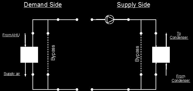
13 4.1. EXAMPLE FOR ENERGYPLUS LINE DIAGRAM GENERATION 13 Figure 4.3: Breakdown of a loop into its constituent half-loops Figure 4.4: A component in the loop


14 14 CHAPTER 4. GENERATING AN ENERGYPLUS LINE DIAGRAM Figure 4.5: Node placement on components Figure 4.6: Nodes in the system


15 4.1. EXAMPLE FOR ENERGYPLUS LINE DIAGRAM GENERATION 15 nodes, and should contain at least one component. The branches are denoted by the blue lines in Figure 4.7. Figure 4.7: Branch definition 7. Identify the position of the connectors in the system. The PlantLoop accepts only one splitter-mixer pair per half loop. The connectors are defined by using branches; a splitter can have one inlet branch and any number of outlet branches whereas a mixer can have any number of inlet branches and one outlet branch. All the connectors in the loop are denoted by the green lines in Figure An EnergyPlus diagram can be generated by using all the identified components. The complete schematic is shown in Figure 4.9.


16 16 CHAPTER 4. GENERATING AN ENERGYPLUS LINE DIAGRAM Figure 4.8: Splitters and mixers in the loop Figure 4.9: Complete EnergyPlus line diagram
17 Chapter 5 Inputting the system into the IDF file Since, it is not possible to input schematics into the input file, it is important to add descriptive comments to all of the entries to ensure that all the components in the system have been accounted for. Such documentation will also make debugging easier. It should be noted that all of the syntax for the inputs is documented in the Input-Output reference guide. A flowchart for the basic input process is provided in Figure


18 18 CHAPTER 5. INPUTTING THE SYSTEM INTO THE IDF FILE Figure 5.1: Flowchart for input process
19 Chapter 6 Example System 1: Chiller and Condenser Loops A simple cooling system will be used as an example to demonstrate the process of inputting a system into the input file. The input file for this example can be found under the name: PlantApplicationsGuide_Example1.idf. This particular system consists of two unique sub-systems/loops. It contains the Plant- Loop with the chiller and the load profile, and another PlantLoop with the cooling tower. A schedule containing previously obtained simulation loads is used to simulate the demand load profile for this loop (Note: In a more general scenario a cooling coil placed in a building zone would provide the load profile). Flow diagrams along with some keywords from the input file will be used to record to steps that are required to properly input the system into EnergyPlus. The simple line diagram for this system is provided in Figure 6.1. The complete EnergyPlus schematic for the system is provided in Figure 6.2. Figure 6.1: Simple cooling system line diagram The cooling system consists of a chilled water loop which is defined by the PlantLoop object, and a condenser loop which is also defined by the PlantLoop object. Identification of 19

 loop The chilled water loop is constructed by using a PlantLoop object.")


20 20 CHAPTER 6. EXAMPLE SYSTEM 1: CHILLER AND CONDENSER LOOPS Figure 6.2: EnergyPlus line diagram for the simple cooling system these loops in the system is critical for the process of modeling the system in the input file the flowchart for loop identification is provided in Figure 6.3. Figure 6.3: Flowchart for loop identification 6.1 Chilled water (CW) loop The chilled water loop is constructed by using a PlantLoop object. This loop uses a watercooled electric chiller to supply chilled water to the demand side of this loop. As mentioned above, the cooling coil is replaced by a load profile object that contains the demand load profile. The chiller is operated by using set points, plant equipment operation schemes and schedules. Refer to Figure 6.4 for a simple diagram of the Chilled Water Loop Flowcharts for the CW Loop Input Process This series of flow charts serve as a process guide for identifying and inputting the chilled water loop and its components into the input file. Refer to Figure 6.5 for an EnergyPlus schematic of the Chilled Water Loop. The PlantLoop object is entered into the input file, with water as the working fluid. The supply side of the chilled water loop is then input into the system followed by the demand side. A flow chart for separating the half loops in the loop is provided in Figure 6.6.
 LOOP 21 Figure")


21 6.1. CHILLED WATER (CW) LOOP 21 Figure 6.4: Simple line diagram for the chilled water loop Figure 6.5: EnergyPlus line diagram for the chilled water loop

22 22 CHAPTER 6. EXAMPLE SYSTEM 1: CHILLER AND CONDENSER LOOPS Figure 6.6: Simple flowchart for separation of half loops in the chilled water loop CW Loop Supply Side Loop Construction The main components in the supply side of the chilled water loop are the circulation pump for the chilled water and the electric chiller that supplies the chilled water. The set-point is set to the outlet node of this half of the loop; the temperature at this node is controlled to regulate the operation of the chiller. This side of the loop has eight nodes, four components and four branches, while it is not required to define individual node positions in the loop, the components and branches have to be defined with an inlet and an outlet node. Connectors are the objects that connect the branches together and complete the loop. Therefore, the branches and the connectors will set the positions of the nodes in the loop. The EnergyPlus line diagram for the Chilled Water Loop supply side is provided in Figure 6.7. The flowchart for supply side branches and components is provided in Figure 6.8. The flowchart for the supply side connectors is provided in Figure CW Loop Demand Side Loop Construction The demand side of the loop is entered next. The main component in this side of the loop is the cooling load profile(instead of the cooling coil). This load profile is input by using a Schedule:Compact object which indicates the hourly cooling loads for the annual run period. In a more general scenario a cooling coil would take the place of the load profile and the cooling load will be simulated from the data obtained in the building system energy simulation. Apart from the load profile, the structure of the loop is very similar to the structure of the supply side. This side of the loop also has eight nodes, four components,


23 6.1. CHILLED WATER (CW) LOOP 23 Figure 6.7: EnergyPlus line diagram for the supply side of the chilled water loop Figure 6.8: Flowchart for chilled water loop supply side branches and components

24 24 CHAPTER 6. EXAMPLE SYSTEM 1: CHILLER AND CONDENSER LOOPS Figure 6.9: Flowchart for chilled water loop supply side connectors and four branches. An EnergyPlus schematic for the demand side is provided in Figure The flowchart for demand side branch definition is provided in Figure The flowchart for the demand side connectors is provided in Figure As shown in the flowchart above, the load profile is attached to the chilled water loop at its designated position (the LoadProfile:Plant object can be used just like any other component) on the demand side of the loop Flowcharts for CW Loop Controls The chilled water loop is operated by using set-points, plant equipment operation schemes and schedules Chilled Water Loop Schedules The chilled water loop uses two different schedules to operate properly. The Chiller AlwaysOnSchedule is a compact schedule that keeps the chiller ON at all times of the day for a whole year. This compact schedule uses a discrete ScheduleTypeLimit (CW Loop On/Off) which defines that the value of On is 1 and that of Off is 0. This plant loop also uses another compact schedule named CW Loop Temp Schedule to set the temperature at the chilled water loop outlet node. This schedule uses a schedule type limit named CW Loop Any Number. The flowchart for chilled water loop schedule definition is provided in Figure Chilled Water Loop Plant Equipment Operation Schemes The PlantEquipmentOperationschemes object uses the Chiller AlwaysOnSchedule and the CW Loop Cooling Load objects to set the range of the demand load for which the chiller


25 6.1. CHILLED WATER (CW) LOOP 25 Figure 6.10: EnergyPlus line diagram for the demand side of the chilled water loop Figure 6.11: Flowchart for chilled water loop demand side branches and components


26 26 CHAPTER 6. EXAMPLE SYSTEM 1: CHILLER AND CONDENSER LOOPS Figure 6.12: Flowchart for chilled water loop demand side connectors Figure 6.13: Flowchart for chilled water loop schedules


27 6.1. CHILLED WATER (CW) LOOP 27 can be operated during the simulation period. Operation schemes are especially useful and crucial when using multiple active components. For example, the performance of multiple chillers can be optimized by carefully managing the load ranges on each of the chillers. A flowchart detailing the chilled water loop plant equipment operation schemes is provided in Figure Figure 6.14: Flowchart for chilled water loop plant equipment operation schemes Chilled Water Loop Setpoints The Chilled Water Loop Setpoint Manager uses the CW Loop Temp Schedule to set a temperature control point at the CW Supply Outlet Node. This setpoint allows the program to control the temperature at the node by operating the components in the chilled water loop. Since, setpoint managers are high-level control objects, their usefulness is realized in much more complex systems, where multiple nodes have to be monitored in order to operate the system properly. A flowchart for chilled water loop setpoints is provided in Figure Figure 6.15: Flowchart for chilled water Loop setpoints
28 28 CHAPTER 6. EXAMPLE SYSTEM 1: CHILLER AND CONDENSER LOOPS Chilled Water Loop Sizing The chilled water loop is sized such a way that the design loop exit temperature is 7 degrees Celsius, and the loop design temperature difference is 5 degrees Celsius. A flowchart for the chilled water loop sizing is provided in Figure Note: Since the Load Profile object does not demand any feedback from the PlantLoop object, the chilled water loop does not necessarily need to be sized (This object is commented out in the example file). The sizing shown here is just an example of how the object class can be used in EnergyPlus. Figure 6.16: Flowchart for chilled water loop sizing 6.2 Condenser Loop The condenser loop uses a cooling tower to supply cooling water to the water-cooled electric chiller in the chilled water loop. Hence, the supply side of this loop consists of the cooling tower and the demand side consists of the electric chiller. The schedules for this loop are almost identical to the ones applied on the CW loop. They dictate that the cooling tower also works around the year. The plant equipment schemes specify the cooling capacity/load of the cooling tower. The operation of the cooling tower is managed by monitoring the outdoor air wet bulb (air cooled condenser) temperature at the location of the simulation. The structure of this loop is very similar to that of the chilled water loop, the only difference being the main components in the loop. A simple line diagram of the condenser loop is provided in Figure Flowcharts for the Condenser Loop Input Process As discussed in Section 1 the supply side and the demand side of the loop are modeled separately by following the process provided in the flow chart. The flow charts for this loop are provided below. A PlantLoop object is used to model the condenser loop with the chiller and the cooling tower as its main components. The working fluid is water. This loop is also sized such that the loop exit temperature is set to 20 degrees Celsius and the loop design temperature
.")

29 6.2. CONDENSER LOOP 29 Figure 6.17: Simple line diagram for the condenser loop difference is 5 degrees Celsius. The chiller serves as the bridge between the chilled water loop and the condenser loop. This is achieved by managing the nodal connections on the chiller, hence the chiller appears on two branches in the system (supply branch of the CW loop, and the demand branch of the condenser loop). The EnergyPlus line diagram for the condenser loop is provided in Figure A simple flow chart for the separation of the half loops is provided in Figure Condenser Loop Supply Side Construction The main components in the supply side of the condenser loop are the condenser circulation pump and the cooling tower. The temperature set-point is set at the outlet node, where the outdoor air wet bulb temperature is monitored to regulate the operation of the cooling tower. The outdoor air conditions are obtained from the weather information file during the simulation. This side of the loop has eight nodes and four branches. An EnergyPlus diagram for the condenser loop supply side is provided in Figure The flowchart for supply side branch definition is provided in Figure The flowchart for the supply side connectors is provided in Figure Condenser Loop Demand Side Construction The central component of the demand side is the chiller. The flowchart for the construction of the demand side is also provided below. The schedules for this side do not need to


30 30 CHAPTER 6. EXAMPLE SYSTEM 1: CHILLER AND CONDENSER LOOPS Figure 6.18: EnergyPlus line diagram for the condenser loop Figure 6.19: Simple flowchart for separation of half loops in the condenser loop

31 6.2. CONDENSER LOOP 31 Figure 6.20: EnergyPlus line diagram for the supply side of the condenser loop


32 32 CHAPTER 6. EXAMPLE SYSTEM 1: CHILLER AND CONDENSER LOOPS Figure 6.21: Flowchart for condenser supply side branches and components Figure 6.22: Condenser loop supply side connectors


33 6.2. CONDENSER LOOP 33 be specified, because the schedules that apply to the chiller also apply to this side of the condenser loop. This side of the loop also contains eight nodes and four branches. An EnergyPlus schematic for the demand side is provided in Figure The flowchart for demand side branch definition is provided in Figure The flowchart for the demand side connectors is provided in Figure Figure 6.23: EnergyPlus line diagram for the demand side of the condenser loop Flowcharts for Condenser Loop Controls The cooling tower is also scheduled similar to the chiller because both of these units have to work together in order to satisfy the cooling load. The operation of the cooling tower is determined by using a set point at the condenser supply exit node. This set point monitors the temperature at this node as well as the outdoor air wet bulb temperature to operate the cooling tower. The flowchart for the schedules, plant equipment schemes, and the set points are also provided below.


34 34 CHAPTER 6. EXAMPLE SYSTEM 1: CHILLER AND CONDENSER LOOPS Figure 6.24: Condenser loop demand side construction Figure 6.25: Condenser loop demand side schedules, equipment schemes and setpoints
 which defines that the value of On is 1 and that of Off is 0. A flowchart for condenser loop schedules is provided in Figure 6.26. Figure 6.26: Condenser loop schedules 6.")

35 6.2. CONDENSER LOOP Condenser Loop Schedules The Tower AlwaysOnSchedule is a compact schedule that keeps the tower ON at all times of the day for a whole year, this compact schedule uses a discrete scheduletypelimit (Tower On/Off) which defines that the value of On is 1 and that of Off is 0. A flowchart for condenser loop schedules is provided in Figure Figure 6.26: Condenser loop schedules Condenser Loop Plant Equipment Operation Schemes The plant equipment operation schemes for the condenser loop are very similar to those of the chilled water loop. The PlantEquipmentOperationschemes object uses the Tower AlwaysOnSchedule and the Tower Load objects to set the range of the demand loads for which the cooling tower is operated during the simulation period. A flowchart for the condenser loop plant equipment operation schemes is provided in Figure Condenser Loop Setpoints The Condensercontrol setpointmanager places a temperature setpoint at the Condenser Supply Outlet Node. The temperature at this point is controlled with respect to the outdoor air wet bulb temperature at that point in the simulation. The outdoor air wet bulb temperature is obtained from the weather data at the location of the simulation. A flowchart for the condenser loop setpoint is provided in Figure 6.28.


36 36 CHAPTER 6. EXAMPLE SYSTEM 1: CHILLER AND CONDENSER LOOPS Figure 6.27: Condenser loop plant equipment operation schemes Figure 6.28: Condenser loop setpoints

37 6.2. CONDENSER LOOP Condenser Loop Sizing The condenser loop is sized such that the loop exit temperature is 20 degrees Celsius and the loop temperature difference is 5 degrees Celsius. A flowchart for condenser loop sizing is provided in Figure Figure 6.29: Condenser loop sizing
38 Chapter 7 Example System 2: Thermal Energy Storage This system will detail the process required to model a Plant Loop coupled with Thermal Energy Storage (TES) in EnergyPlus. The input file for this example can be found under the name: PlantApplicationsGuide_Example2.idf. The TES tank will be charged by using a chiller loop, which will in turn be cooled by a condenser loop. The schedules for this system are setup such that the TES tank will be charged by the chiller during the night and then the stored chilled water is used to satisfy the building cooling load during the day. The TES tank used in this system is a stratified tank. This system also includes one heating loop which satisfies the heating load. The cooling and heating system operate in conjunction with an air loop that is spread across a total of five zones. The air loop modeling will not be discussed in this guide. This system consists of a total of three separate plant loops, the cooling side is comprised of two loops and the heating side contains one loop. A simple line diagram for the cooling system is provided in Figure 7.1. The EnergyPlus line diagram for the cooling loop is provided in Figure 7.3. A simple line diagram for the heating loop is provided in Figure 7.2, whereas its EnergyPlus line diagram is provided in Figure 7.4. SHWSys1 The cooling side of the system will be modeled first. The primary cooling loop (named CoolSysPrimary in the input file) uses the chiller as the supply side component to charge the TES tank. The chilled water that is stored in the TES tank is then supplied to the cooling coil. A cooling tower that operates on the supply side of the condenser loop (named Condenser Loop ) supplies the cooling water to the chiller that is used in the primary cooling loop. These two loops serve as the cooling system for this building. This system will be modeled first with emphasis placed on the primary cooling loop. In particular the schedules used for the charging and discharging the TES tank play a crucial role in the efficient operation of the system. The building also has one heating loop. The heating loop (named HeatSys 1 ) uses a boiler to provide hot water to five heating coils that are located in the five zones. This heating loop also supplies hot water to the reheat coil. A flow chart for loop identification is provided in Figure


39 39 Figure 7.1: Simple line diagram for cooling system Figure 7.2: Simple line diagram for heating loop


40 40 CHAPTER 7. EXAMPLE SYSTEM 2: THERMAL ENERGY STORAGE Figure 7.3: EnergyPlus line diagram for cooling system Figure 7.4: EnergyPlus line diagram for heating loop
 - Chiller The primary cooling system is constructed by using a PlantLoop object.")

41 7.1. PRIMARY COOLING LOOP (COOLSYSPRIMARY) - CHILLER 41 Figure 7.5: Flowchart for loop identification 7.1 Primary Cooling Loop (CoolSysPrimary) - Chiller The primary cooling system is constructed by using a PlantLoop object. It uses an electric chiller that generates chilled water which is used to charge the TES tank at night. The chilled water stored in the TES tank is later used during the peak hours to satisfy the demand loads. Therefore, the supply side of the loop contains the electric chiller and the charge side of the TES tank. The demand side loop contains the cooling coil. The loop is operated by using plant equipment operation schemes, and schedules. Refer to Figure 7.6 for a simple diagram of the Primary Cooling Loop Flowcharts for the Primary Cooling Loop Input Process This series of flowcharts serve as a guide for identifying and inputting the CoolSysPrimary loop and its components into the input file. The working fluid in this loop is water. The important area for this loop is its controls. The EnergyPlus line diagram for this loop is provided in Figure 7.7. A simple flowchart for the separation of the half loops is provided in Figure CoolSysPrimary Supply Side Loop Construction The main components on the supply side half loop for the primary cooling system are the electric chiller that supplies the chilled water, the variable speed pump that circulates the chilled water through the loop, and the TES tank that stores the supplied chilled water. This half loop supplies chilled water to the cooling coil which is placed on the demand side half loop. The supply side half loop contains five components, four branches, nine nodes, and one splitter-mixer pair. The EnergyPlus line diagram for the primary cooling loop supply side is provided in Figure 7.9. The flowchart for supply side branches and components is provided in Figure The flowchart for supply side connectors is provided in Figure 8.9.


42 42 CHAPTER 7. EXAMPLE SYSTEM 2: THERMAL ENERGY STORAGE Figure 7.6: Simple line diagram for the primary cooling system Figure 7.7: EnergyPlus line diagram for the primary cooling system

43 7.1. PRIMARY COOLING LOOP (COOLSYSPRIMARY) - CHILLER 43 Figure 7.8: Simple flowchart for the separation of half-loops in the primary cooling system CoolSysPrimary Demand Side Loop Construction The main component on the demand side half loop is the cooling coil which cools the air in the building by using the chilled water that is supplied by the supply side half loop. This side of the loop has eight nodes, four components, four branches, and one splitter mixer pair. An EnergyPlus line diagram for the demand side is provided in Figure The flowchart for demand side branch definition is provided in Figure The flowchart for the demand side connectors is provided in Figure Flowcharts for Primary Cooling Loop Controls The Primary Cooling loop is operated by using set-points, plant equipment operation schemes and schedules. The TES tank charging schedule is one of the most important schedules in this system CoolSysPrimary Schedules The flowchart for Primary Cooling loop schedule definition is provided in Figure 56. The Primary Cooling loop uses five different schedules to operate properly. The PlantOnSchedule is a compact schedule that keeps the chiller and the TES tank ON at all times of the day, this compact schedule uses a discrete ScheduleTypeLimit (On/Off) which defines that the value of On is 1 and that of Off is 0. This plant loop also uses another compact schedule named CW Primary Loop Temp Schedule declare that the temperature of the chilled water loop outlet flow is 6.7 degrees Celsius at all times. This schedule is used by the setpoint


44 44 CHAPTER 7. EXAMPLE SYSTEM 2: THERMAL ENERGY STORAGE Figure 7.9: EnergyPlus line diagram for the supply side of the primary cooling loop
 - CHILLER 45")


45 7.1. PRIMARY COOLING LOOP (COOLSYSPRIMARY) - CHILLER 45 Figure 7.10: Flowchart for primary cooling loop supply side branches and components Figure 7.11: Flowchart for primary cooling loop supply side connectors

46 46 CHAPTER 7. EXAMPLE SYSTEM 2: THERMAL ENERGY STORAGE Figure 7.12: EnergyPlus line diagram for the demand side of the primary cooling loop

47 7.1. PRIMARY COOLING LOOP (COOLSYSPRIMARY) - CHILLER 47 Figure 7.13: Flowchart for primary cooling loop demand side branches and components Figure 7.14: Flowchart for primary cooling loop demand side connectors
48 48 CHAPTER 7. EXAMPLE SYSTEM 2: THERMAL ENERGY STORAGE manager (CoolSysPrimary Loop Setpoint Manager). This schedule uses a schedule type limit named Temperature, which defines the upper and lower loop temperature limits The compact schedule ALWAYS_ON dictates that the use/discharge side of the TES tank is On at all times of the day. This schedule uses the ScheduleTypeLimit (Fraction) to set the fractional flow rate of the use side. This schedule is used to define the use side availability of the TES tank. The compact schedule CW Tank Temp Schedule is input in the TES tank object class to define the limits of the temperature for the chilled water storage tank outlet. This schedule uses the ScheduleTypeLimit (Temperature) to define that the temperature at that outlet should be 7.5 degrees Celsius at all times of the day. The TES Charge Schedule is a very important schedule for the functioning of the Cool- SysPrimary Loop the schedule from the input file is provided in Figure The schedule shows that, the on/off ScheduleTypeLimit is used to determine if the TES schedule is On or off for a certain period of time. A value of 1.0 means On and a value of 0 means Off. For example, it can be observed from the figure that, for the weekdays the TES tank is charged until 10:00AM, then it is operated during the day from 10:00 AM to 5:00 PM and then it is charged until midnight. The schedule for the other days is also shown in the figure. Figure 7.15: TES Charge Schedule CoolSysPrimary Plant Equipment Operation Schemes This loop has two plant equipment operation schemes, one for the chiller and one for the TES tank. The PlantEquipmentOperationschemes object uses the PlantOnSchedule and the CoolSysPrimary Operation Scheme objects to set the range of demand loads for which the chiller is operated during the simulation period. Operation schemes are especially useful and crucial when using multiple active components. For example, the performance of multiple chillers can be optimized by carefully managing the load ranges on each of the chillers. It should be noted that it is required to enter a plant equipment operation scheme for every
 - CHILLER")

49 7.1. PRIMARY COOLING LOOP (COOLSYSPRIMARY) - CHILLER 49 Figure 7.16: Flowchart for primary cooling loop schedules

50 50 CHAPTER 7. EXAMPLE SYSTEM 2: THERMAL ENERGY STORAGE plant loop in the system. A flowchart detailing the chilled water loop plant equipment operation schemes is provided in Figure Figure 7.17: Flowchart for Chiller plant equipment operation schemes The TES tank operation is modeled here. The PlantEquipmentOperationschemes object uses the PlantOnSchedule and the TES Operation Scheme objects to set the range of the demand loads for which the TES tank is operated during the simulation period. A flowchart detailing the Secondary Cooling Loop plant equipment operation schemes is provided in Figure CoolSysPrimary Setpoints The CoolSysPrimary Loop Setpoint Manager uses the CoolSysPrimary Loop Temp Schedule to set a temperature control point at the CoolSysPrimary Supply Outlet Node. This setpoint allows the program to control the temperature at the node by operating the components in the Primary Cooling loop. A flowchart for Secondary Cooling loop setpoints is provided in Figure CoolSysPrimary Sizing The chilled water loop is sized such a way that the design loop exit temperature is 6.7 degrees Celsius, and the loop design temperature difference is 5 degrees Celsius. A flowchart for the Secondary Cooling loop sizing is provided in Figure 7.20.


51 7.1. PRIMARY COOLING LOOP (COOLSYSPRIMARY) - CHILLER 51 Figure 7.18: Flowchart for Thermal Energy Storage plant equipment operation schemes Figure 7.19: Flowchart for primary cooling loop setpoints Figure 7.20: Flowchart for primary cooling loop sizing
 and a constant speed pump (modeled by using a Pump:ConstantSpeed) to supply cooling water to the electric chiller")

52 52 CHAPTER 7. EXAMPLE SYSTEM 2: THERMAL ENERGY STORAGE 7.2 Condenser Loop (Condenser Loop) - Cooling Tower The Condenser Loop is constructed by using a PlantLoop object. It uses a cooling tower (modeled by using a CoolingTower:SingleSpeed object class) and a constant speed pump (modeled by using a Pump:ConstantSpeed) to supply cooling water to the electric chiller (modeled by using a Chiller:Electric object). Therefore, the supply side of the loop contains the Cooling Tower and the demand side contains the electric chiller. The loop is operated by using plant equipment operation schemes, and schedules. Refer to Figure 7.21 for a simple diagram of the Condenser Loop. Figure 7.21: Simple line diagram for the condenser loop Flowcharts for the Condenser Loop Input Process This series of flowcharts serve as a guide for identifying and inputting the Condenser Loop and its components into the input file. The EnergyPlus line diagram for this loop is provided in Figure A simple flowchart for the separation of the half loops is provided in Figure Condenser Loop Supply Side Construction The main components on the supply side half loop for the Condenser Loop are the Cooling Tower that supplies the cooling water and the constant speed pump that circulates the cooling


53 7.2. CONDENSER LOOP (CONDENSER LOOP) - COOLING TOWER 53 Figure 7.22: EnergyPlus line diagram for the condenser loop Figure 7.23: Simple flow chart for separation on half loops in the condenser loop
54 54 CHAPTER 7. EXAMPLE SYSTEM 2: THERMAL ENERGY STORAGE water through the loop. This half loop supplies cooling water to the electric chiller on the demand side half loop. The supply side half loop contains four components, four branches, eight nodes, and one splitter-mixer pair. The EnergyPlus line diagram for the Condenser loop supply side is provided in Figure The flowchart for supply side branches and components is provided in Figure The flowchart for supply side connectors is provided in Figure Figure 7.24: EnergyPlus line diagram for the supply side of the condenser loop Condenser Loop Demand Side Construction The main component on the demand side half loop is the Chiller that uses the cooling water supplied by the cooling tower. The chiller in turn is used to supply chilled water in
 - COOLING TOWER 55 Figure")


55 7.2. CONDENSER LOOP (CONDENSER LOOP) - COOLING TOWER 55 Figure 7.25: Flowchart for condenser loop supply side branches and components Figure 7.26: Flowchart for condenser loop supply side connectors

56 56 CHAPTER 7. EXAMPLE SYSTEM 2: THERMAL ENERGY STORAGE the Primary Cooling loop. This side of the loop also has eight nodes, four components, four branches and one splitter-mixer pair. An EnergyPlus schematic for the demand side is provided in Figure The flowchart for demand side branch definition is provided in Figure The flowchart for the demand side connectors is provided in Figure Figure 7.27: EnergyPlus line diagram for the demand side of the condenser loop Flowcharts for Condenser Loop Controls The Condenser Loop is operated by using set-points, plant equipment operation schemes and schedules Condenser Loop Schedules The flowchart for condenser loop schedule definition is provided in Figure The Condenser loop uses one schedule to operate properly. PlantOnSchedule is a compact schedule
57 7.2. CONDENSER LOOP (CONDENSER LOOP) - COOLING TOWER 57 Figure 7.28: Flowchart for condenser loop demand side branches and components Figure 7.29: Flowchart for condenser loop demand side connectors
 which defines that the value of On")
58 58 CHAPTER 7. EXAMPLE SYSTEM 2: THERMAL ENERGY STORAGE that keeps the Cooling Tower On at all times of the day, this compact schedule uses a discrete ScheduleTypeLimit (On/Off) which defines that the value of On is 1 and that of Off is 0. Figure 7.30: Flowchart for condenser loop schedules Condenser Loop Plant Equipment Operation Schemes The PlantEquipmentOperationschemes object uses the PlantOnSchedule and the Condenser Loop Operation Scheme objects to set the range of demand loads for which the cooling tower is operated during the simulation period. A flowchart detailing the Condenser Loop plant equipment operation schemes is provided in Figure Condenser Loop Setpoints The MyCondenserControl setpointmanager places a temperature setpoint at the Condenser Supply Outlet Node. The temperature at this point is controlled with respect to the outdoor air wet bulb temperature at that point in the simulation. The outdoor air wet bulb temperature is obtained from the weather data at the location of the simulation. The minimum setpoint temperature is 5 degrees Celsius and the maximum setpoint temperature is 80 degrees Celsius. A flowchart for Secondary Cooling loop setpoints is provided in Figure 7.32.

59 7.2. CONDENSER LOOP (CONDENSER LOOP) - COOLING TOWER 59 Figure 7.31: Flowchart for condenser loop plant equipment operation schemes Figure 7.32: Flowchart for condenser loop setpoints

 to supply hot water to the five heating coils placed in the five zones of the building (modeled by using a")
60 60 CHAPTER 7. EXAMPLE SYSTEM 2: THERMAL ENERGY STORAGE Condenser Loop Sizing The Condenser loop is sized such a way that the design loop exit temperature is 29.4 degrees Celsius, and the loop design temperature difference is 5.6 degrees Celsius. A flowchart for the chilled water loop sizing is provided in Figure Figure 7.33: Flowchart for condenser loop sizing 7.3 Heating Loop (HeatSys1) - Boiler The Heating loop is constructed by using a PlantLoop object. It uses an electric boiler to (modeled by using a Boiler:HotWater object class) to supply hot water to the five heating coils placed in the five zones of the building (modeled by using a Coil:Heating:Water object class). Therefore, the supply side of the loop contains the hot water boiler and the demand side contains a total of six heating coils. The loop is operated by using plant equipment operation schemes, and schedules. Refer to Figure 7.34 for a simple diagram of the Condenser Loop. Figure 7.34: Simple line diagram for the heating loop

61 7.3. HEATING LOOP (HEATSYS1) - BOILER Flowcharts for the Heating Loop Input Process This series of flowcharts serve as a guide for identifying and inputting the Heating loop and its components into the input file. The EnergyPlus line diagram for this loop is provided in Figure A simple flowchart for the separation of the half loops is provided in Figure Figure 7.35: EnergyPlus line diagram for the heating loop Heating Loop Supply Side Construction The main components on the supply side half loop for the Heating Loop are the hot water boiler that generates hot water and the variable speed pump that circulates the hot water through the loop. This half loop supplies hot water to five heating coils on the demand side half loop. The supply side half loop contains four components, four branches, eight nodes, and one splitter-mixer pair. The EnergyPlus line diagram for the Primary Cooling loop supply side is provided in Figure The flowchart for supply side branches and components is provided in Figure The flowchart for supply side connectors is provided in Figure Heating Loop Demand Side Construction The demand side half loop contains five heating coils that heat the air in the different zones of the building by using the hot water that is supplied by the hot water boiler. This side of the loop also has sixteen nodes, eight components, eight branches, and one splitter-mixer pair. An EnergyPlus schematic for the demand side is provided in Figure The flowchart for demand side branch definition is provided in Figure The flowchart for the demand side connectors is provided in Figure Flowcharts for Heating Loop Controls The Heating Loop is operated by using set-points, plant equipment operation schemes and schedules.
62 62 CHAPTER 7. EXAMPLE SYSTEM 2: THERMAL ENERGY STORAGE Figure 7.36: Simple flow chart for separation on half loops in the heating loop Heating Loop Schedules The flowchart for Primary Heating loop schedule definition is provided in Figure The Heating Loop uses three different schedules to operate properly. PlantOnSchedule is a compact schedule that uses a discrete ScheduleTypeLimit (On/Off) which defines that the value of ON is 1 and that of Off is 0. This plant loop also uses another compact schedule named HW Loop Temp Schedule to declare that the temperature at the heating loop outlet and the boiler outlet to be 82 degrees Celsius. This schedule uses a schedule type limit named Temperature, which defines the loop upper and lower temperature limits. The compact schedule ALWAYS_ON dictates that the boiler and the cooling coils are On at all times of the day. This schedule uses the ScheduleTypeLimit (Fraction) to set the fractional flow rate of the components to Heating Loop Plant Equipment Operation Schemes The PlantEquipmentOperationschemes object uses the PlantOnSchedule and the HeatSys1 Operation Scheme objects to set the range of the demand loads for which the boiler is operated during the simulation period. Operation schemes are especially useful and crucial when using multiple active components but it is required to enter set up a plant equipment operation scheme for every PlantLoop that is used in a system. A flowchart detailing the heating loop plant equipment operation scheme is provided in Figure 7.44.


63 7.3. HEATING LOOP (HEATSYS1) - BOILER 63 Figure 7.37: EnergyPlus line diagram for the supply side of the heating loop


64 64 CHAPTER 7. EXAMPLE SYSTEM 2: THERMAL ENERGY STORAGE Figure 7.38: Flowchart for heating loop supply side branches and components Figure 7.39: Flowchart for heating loop supply side connectors


65 7.3. HEATING LOOP (HEATSYS1) - BOILER 65 Figure 7.40: EnergyPlus line diagram for the demand side of the heating loop Figure 7.41: Flowchart for heating loop demand side branches and components


66 66 CHAPTER 7. EXAMPLE SYSTEM 2: THERMAL ENERGY STORAGE Figure 7.42: Flowchart for heating loop demand side connectors Figure 7.43: Flowchart for heating loop schedules

67 7.3. HEATING LOOP (HEATSYS1) - BOILER 67 Figure 7.44: Flowchart for heating loop plant equipment operation schemes Heating Loop Setpoints The HeatSys1 Loop Setpoint Manager uses the HW Loop Temp Schedule to set a temperature control point at the HeatSys1 Supply Outlet Node. This setpoint allows the program to control the temperature (set to 82 degrees Celsius) at the node by operating the components in the Heating loop. The Heating Loop also uses another schedule (HeatSys1 Boiler Setpoint Manager) to set the temperature of the boiler outlet to 82 degrees Celsius. If the HeatSys1 Boiler Setpoint Manager is not entered the program assumes the overall loop setpoint for the boiler outlet node. Since, setpoint managers are high-level control objects, their usefulness is realized in much more complex systems, where multiple nodes have to be monitored in order to operate the system properly. A flowchart for heating loop setpoints is provided in Figure Figure 7.45: Flowchart for heating loop setpoints

68 68 CHAPTER 7. EXAMPLE SYSTEM 2: THERMAL ENERGY STORAGE Heating Loop Sizing The Heating Loop is sized such a way that the design loop exit temperature is 82.0 degrees Celsius, and the loop design temperature difference is 11.0 degrees Celsius. A flowchart for the chilled water loop sizing is provided in Figure Figure 7.46: Flowchart for heating loop sizing

69 Chapter 8 Example System 3: Primary/Secondary Pumping This example will discuss the basics of primary/secondary pumping systems and some of the controls that are used in managing such systems. The input file for this example can be found under the name: PlantApplicationsGuide_Example3.idf. Although it is common for these systems to have a common pipe setup to allow for flow imbalance as shown in Figure 8.1 and even though there is a provision in EnergyPlus to model common pipes, this example will not discuss them. In the future, the common pipe is expected to be obsolesced, and therefore using a heat exchanger and two separate loops is recommended for future primary/secondary pumping arrangements. Figure 8.1: Example of a common pipe setup This system services a three zone building by using, two chillers and purchased cooling on the primary chilled water loop to satisfy the demand loads. The chilled water from the supply side of the primary chilled water loop is passes through a plate heat exchanger which serves as the supply side for the secondary chilled water loop. The cooling coil is placed on the demand side of the secondary loop. The primary loop uses a constant speed pump 69

 which contains a small chiller, a big chiller and a purchased cooling object on the supply side half loop for supplying chilled water to a")
70 70 CHAPTER 8. EXAMPLE SYSTEM 3: PRIMARY/SECONDARY PUMPING to circulate the working fluid (water). The secondary loop uses a variable speed pump to manipulate the flow of the fluid such that the cooling coil demand is satisfied. The above mentioned pumps are considered as a primary/secondary pumping pair. Therefore there are four different loops in the system. The cooling loops in the system will be modeled first. The primary cooling loop ( Primary Chilled Water Loop ) which contains a small chiller, a big chiller and a purchased cooling object on the supply side half loop for supplying chilled water to a fluid to fluid plate heat exchanger on the demand side. The secondary cooling loop ( Secondary Chilled Water Loop ) contains the fluid to fluid plate heat exchanger on the supply side half loop and a cooling coil on the demand side. The condenser loop ( Condenser Loop ) which uses a cooling tower to supply cold water to the chillers on the demand side is modeled next. The heating loop ( Heating Loop ) uses purchased heating to serve the demand loads of three reheat coils places in each of the zones of the buildings, this loop will not be discussed in this application guide because it does not relate to the primary/secondary pumping setup in any way. The plant equipment operation scheme for the primary chilled water loop and the primary/secondary pumping setup are the most important features of this system. The simple line diagram for the system is shown in Figure 8.3. The EnergyPlus line diagram is shown in Figure 8.3. Figure 8.2: Simple line diagram for the cooling system 8.1 Primary Chilled Water Loop Chiller(s) and purchased cooling The Secondary Cooling system is constructed by using a PlantLoop object. It uses two chillers (a small constant COP chiller and a bigger electric chiller) and purchased district cooling. Therefore, the supply side of the loop contains the chillers and the purchased cooling, and the demand side contains one side of the plate heat exchanger. The loop is operated by using plant equipment operation schemes and schedules. Refer to Figure 8.4 for a simple diagram of the Primary Cooling Loop.
 AND PURCHASED")

71 8.1. PRIMARY CHILLED WATER LOOP CHILLER(S) AND PURCHASED COOLING71 Figure 8.3: EnergyPlus line diagram for the cooling system


72 72 CHAPTER 8. EXAMPLE SYSTEM 3: PRIMARY/SECONDARY PUMPING Figure 8.4: Simple line diagram for the primary chilled water loop Flowcharts for the Primary Chilled Water Loop Input Process This series of flowcharts serve as a guide for identifying and inputting the Primary Chilled Water loop and its components into the input file. The working fluid in this loop is water. The EnergyPlus line diagram for this loop is provided in Figure 8.5. A simple flowchart for the separation of the half loops is provided in Figure 8.6. Figure 8.5: EnergyPlus line diagram for the primary chilled water loop
73 8.1. PRIMARY CHILLED WATER LOOP CHILLER(S) AND PURCHASED COOLING73 Figure 8.6: Simple flowchart for the separation of half-loops in the primary chilled water loop Primary Cooling System Supply Side Loop Construction The main components on the supply side half loop for the primary chilled water loop are two chillers and district cooling object that supply chilled water and the constant speed pump that circulates the chilled water through the loop. This pump ( CW Primary Circ Pump ) is the primary pump in the primary/secondary pumping setup. This half loop supplies chilled water to the plate heat exchanger which is placed on the demand side half loop. The supply side half loop contains six components, six branches, twelve nodes, and one splitter-mixer pair. The EnergyPlus line diagram for the Primary Cooling loop supply side is provided in Figure 8.7. The flowchart for supply side branches and components is provided in Figure 8.8. The flowchart for supply side connectors is provided in Figure Primary Cooling Loop Demand Side Loop Construction The main component on the demand side half loop is the plate heat exchanger that facilitates the exchange of heat between the fluids of the primary and secondary chilled water loop. The plate heat exchanger will not be discussed in this loop. Instead the object will be discussed in the supply side half loop of the secondary chilled water loop. This side of the loop also has eight nodes, four components, four branches, and one splitter mixer pair. An EnergyPlus schematic for the demand side is provided in Figure The flowchart for demand side branch definition is provided in Figure The flowchart for the demand side connectors is provided in Figure 8.12.


74 74 CHAPTER 8. EXAMPLE SYSTEM 3: PRIMARY/SECONDARY PUMPING Figure 8.7: EnergyPlus line diagram for the supply side of the primary chilled water loop Figure 8.8: Flowchart for Primary Cooling Loop supply side branches and components

75 8.1. PRIMARY CHILLED WATER LOOP CHILLER(S) AND PURCHASED COOLING75 Figure 8.9: Flowchart for Primary Cooling Loop supply side branches and components Flowcharts for Primary Chilled Water Loop Controls The Primary Cooling loop is operated by using set-points, plant equipment operation schemes and schedules. The plant equipment scheme for the on peak and off peak operation of the chillers is very important Primary Chilled Water Loop Schedules The Primary Cooling loop uses three different schedules to operate properly. On Peak is a compact schedule that defines the on peak hours (9 AM to 6 PM). The Off Peak is a compact schedule that defines the off peak hours (6 PM to 9 AM). This plant loop also uses another compact schedule named CW Loop Temp Schedule declare that the temperature of the chilled water loop outlet flow is 6.7 degrees Celsius at all times. This schedule is used by the setpoint manager (Primary CW Loop Setpoint Manager). This schedule uses a schedule type limit named Temperature, which defines the loop upper and lower temperature limits. The flowchart for Primary Cooling loop schedule definition is provided in Figure Primary Chilled Water Loop Plant Equipment Operation Schemes There are two important operation schemes in the primary chilled water loop. The CW Loop Operation plant equipment operation scheme used two schedules (On Peak and off Peak) to control the supply components in the primary cooling loop. Peak Operation is set up such that different components or combinations of components are operated for different values of cooling load during the peak hours (9AM to 6PM everyday) of the simulation period. Up to 25,000 W of cooling load, the small constant COP chiller is operated, for 25, ,000 W the big electric chiller and purchased cooling are used and for 245, ,000 W purchased cooling is used. This setup serves to increase the efficiency of the system. Off Peak Operation is set up such that both the chillers are operated during the off peak hours (6 PM to 9 AM).


76 76 CHAPTER 8. EXAMPLE SYSTEM 3: PRIMARY/SECONDARY PUMPING Figure 8.10: EnergyPlus line diagram for the demand side of the primary chilled water loop Figure 8.11: Flowchart for primary chilled water loop demand side branches and components


77 8.2. SECONDARY CHILLED WATER LOOP PLATE HEAT EXCHANGER 77 Figure 8.12: Flowchart for primary chilled water loop demand side connectors Figure 8.13: Flowchart for primary chilled water loop schedules Flowcharts detailing the chilled water loop plant equipment operation schemes are provided in Figure 8.14 and Figure Primary Chilled Water Loop Setpoints The Primary CW Loop Setpoint Manager uses the CW Loop Temp Schedule to set a temperature control point at the CW Primary Supply Outlet Node. This setpoint allows the program to control the temperature at the node by operating the components in the Primary Cooling loop. Since, setpoint managers are high-level control objects, their usefulness is realized in much more complex systems, where multiple nodes have to be monitored in order to operate the system properly. A flowchart for Secondary Cooling loop setpoints is provided in Figure Secondary Chilled Water Loop Plate Heat Exchanger The Secondary Cooling system is constructed by using a PlantLoop object, the working fluid in this loop is water. It uses one side of a plate heat exchanger (modeled using a HeatExchanger:FluidToFluid object) to supply chilled water to a cooling coil (modeled by using a Coil:Cooling:DetailedGeometry object). Therefore, the supply side of the loop contains the heat exchanger and the demand side contains the cooling coil. The loop is operated by


78 78 CHAPTER 8. EXAMPLE SYSTEM 3: PRIMARY/SECONDARY PUMPING Figure 8.14: Flowchart for on peak operation of the primary chilled water loop Figure 8.15: Flowchart for off peak plant operation of the primary chilled water loop


79 8.2. SECONDARY CHILLED WATER LOOP PLATE HEAT EXCHANGER 79 Figure 8.16: Flowchart for Primary Cooling Loop setpoints using plant equipment operation schemes, and schedules. diagram of the secondary chilled water loop. Refer to Figure 8.17 for a simple Figure 8.17: Simple line diagram for the secondary chilled water loop Flowcharts for the Secondary Chilled Water Loop Input Process This series of flowcharts serve as a guide for identifying and inputting the secondary chilled water loop and its components into the input file. The EnergyPlus line diagram for this loop is provided in Figure A simple flowchart for the separation of the half loops is provided in Figure Secondary Chilled Water Loop Supply Side Loop Construction The main components on the supply side half loop for the Secondary Cooling System are the plate heat exchanger that supplies the chilled water and the variable speed pump that circulates the chilled water through the loop. The variable speed pump (named CW Sec Circ Pump ) is the secondary pump in the primary/secondary pumping setup. This half loop


80 80 CHAPTER 8. EXAMPLE SYSTEM 3: PRIMARY/SECONDARY PUMPING Figure 8.18: EnergyPlus line diagram for the secondary chilled water loop Figure 8.19: Simple flow chart for separation on half loops in the secondary chilled water loop


81 8.2. SECONDARY CHILLED WATER LOOP PLATE HEAT EXCHANGER 81 supplies chilled water to a cooling coil on the demand side half loop. The supply side half loop contains four components, four branches, eight nodes, and one splitter-mixer pair. The EnergyPlus line diagram for the secondary chilled water loop supply side is provided in Figure The flowchart for supply side branches and components is provided in Figure The flowchart for supply side connectors is provided in Figure Figure 8.20: EnergyPlus line diagram for the supply side of the secondary chilled water loop Secondary Chilled Water Loop Demand Side Loop Construction The main component on the demand side half loop is the Cooling Coil that cools the air in the building by using the chilled water that is supplied by the plate heat exchanger. This side of the loop also has eight nodes, four components, four branches, and one splitter-mixer pair. An EnergyPlus schematic for the demand side is provided in Figure The flowchart for demand side branch definition is provided in Figure The flowchart for the demand side connectors is provided in Figure 8.25.


82 82 CHAPTER 8. EXAMPLE SYSTEM 3: PRIMARY/SECONDARY PUMPING Figure 8.21: Flowchart for secondary chilled water loop supply side branches and components Figure 8.22: Flowchart for secondary chilled water loop supply side connectors


83 8.2. SECONDARY CHILLED WATER LOOP PLATE HEAT EXCHANGER 83 Figure 8.23: EnergyPlus line diagram for the demand side of the secondary chilled water loop


84 84 CHAPTER 8. EXAMPLE SYSTEM 3: PRIMARY/SECONDARY PUMPING Figure 8.24: Flowchart for secondary chilled water loop demand side branches and components Figure 8.25: Flowchart for secondary chilled water loop demand side connectors

85 8.2. SECONDARY CHILLED WATER LOOP PLATE HEAT EXCHANGER Flowcharts for secondary chilled water loop Controls The secondary chilled water loop is operated by using set-points, plant equipment operation schemes and schedules Secondary Chilled Water Loop Schedules The flowchart for Primary Cooling loop schedule definition is provided in Figure The Secondary Cooling loop uses two different schedules to operate properly. ON is a compact schedule that keeps the plate heat exchanger running at all times of the day, this compact schedule uses a continuous ScheduleTypeLimit (Fraction) which defines that the value of On is 1 and that of Off is 0. This plant loop also uses another compact schedule named CW Sec Loop Temp Schedule declares that the outlet temperature of the Secondary Cooling loop should be 6.67 degrees Celsius at any time; this schedule is used by the setpoint manager (CW Sec Loop Setpoint Manager). This schedule uses a schedule type limit named Temperature, which defines the loop upper and lower temperature limits. Figure 8.26: Flowchart for secondary chilled water loop schedules Secondary Chilled Water Loop Plant Equipment Operation Schemes The PlantEquipmentOperationschemes object uses the ON schedule and the CW Sec Operation Scheme objects to set the range of the demand loads for which the heat exchanger is operated during the simulation period. A flowchart detailing the secondary chilled water loop plant equipment operation schemes is provided in Figure Secondary Chilled Water Loop Setpoints The CW Sec Loop Setpoint Manager uses the CW Sec Loop Temp Schedule to set a temperature control point at the CW Sec Supply Outlet Node. This setpoint allows the program to control the temperature at the node by operating the components in the Secondary Cooling loop. A flowchart for Secondary Cooling loop setpoints is provided in Figure 8.28.

86 86 CHAPTER 8. EXAMPLE SYSTEM 3: PRIMARY/SECONDARY PUMPING Figure 8.27: Flowchart for secondary chilled water loop plant equipment operation schemes Figure 8.28: Flowchart for secondary chilled water loop setpoints

87 8.3. PRIMARY/SECONDARY PUMPING Secondary Chilled Water Loop Sizing The secondary chilled water loop is sized such a way that the design loop exit temperature is 6.67 degrees Celsius, and the loop design temperature difference is 5 degrees Celsius. A flowchart for the chilled water loop sizing is provided in Figure Figure 8.29: Flowchart for secondary chilled water loop sizing 8.3 Primary/Secondary Pumping As mentioned in sections Primary Cooling System Supply Side Loop Construction and Secondary Chilled Water Loop Supply Side Loop Construction, the CW primary Circ Pump and the CW Sec Circ Pump function as the primary/secondary (respectively) pumping system. The primary pump is a constant speed pump that circulates chilled water at a constant flow rate through one side the plate heat exchanger in the primary chilled water loop. The secondary pump is a variable speed pump that circulates chilled water at a variable flow rate through the other side of the plate heat exchanger depending on the demand load. 8.4 Condenser Loop - Cooling Tower The Condenser Loop is constructed by using a PlantLoop object. It uses a cooling tower (modeled by using a CoolingTower:SingleSpeed object class) and a variable speed pump (modeled by using a Pump:VariableSpeed) to supply cooling water to the chillers in the primary cooling loop. Therefore, the supply side of the loop contains the Cooling Tower and the demand side contains the chillers. The loop is operated by using plant equipment operation schemes, and schedules. Refer to Figure 8.30 for a simple diagram of the Condenser Loop.


88 88 CHAPTER 8. EXAMPLE SYSTEM 3: PRIMARY/SECONDARY PUMPING Figure 8.30: Simple line diagram for the condenser loop


89 8.4. CONDENSER LOOP - COOLING TOWER Flowcharts for the Condenser Loop Input Process This series of flowcharts serve as a guide for identifying and inputting the Condenser Loop and its components into the input file. The EnergyPlus line diagram for this loop is provided in Figure A simple flowchart for the separation of the half loops is provided in Figure Figure 8.31: EnergyPlus line diagram for the condenser loop Condenser Loop Supply Side Construction The main components on the supply side half loop for the Condenser Loop are the Cooling Tower that supplies the cooling water and the variable speed pump that circulates the cooling water through the loop. This half loop supplies cooling water to the chillers on the demand side half loop. The supply side half loop contains four components, four branches, eight nodes, and one splitter-mixer pair. The EnergyPlus line diagram for the Condenser loop supply side is provided in Figure The flowchart for supply side branches and components is provided in Figure The flowchart for supply side connectors is provided in Figure 8.35.
90 90 CHAPTER 8. EXAMPLE SYSTEM 3: PRIMARY/SECONDARY PUMPING Figure 8.32: Simple flow chart for separation on half loops in the condenser loop Condenser Loop Demand Side Construction The main components on the demand side half loop are the small constant COP chiller and the bigger electric chiller that use the cooling water supplied by the cooling tower. The chillers are in turn used to supply chilled water in the Primary Cooling loop. This side of the loop also has ten nodes, five components, five branches and one splitter-mixer pair. An EnergyPlus schematic for the demand side is provided in Figure The flowchart for demand side branch definition is provided in Figure The flowchart for the demand side connectors is provided in Figure Flowcharts for Condenser Loop Controls The Condenser loop is operated by using set-points, plant equipment operation schemes and schedules Condenser Loop Schedules The flowchart for condenser loop schedule definition is provided in Figure The Condenser loop uses one schedule to operate properly. ON is a compact schedule that keeps the Cooling Tower On at all times of the day, this compact schedule uses a continuous ScheduleTypeLimit (Fraction) which defines that the value of On is 1 and that of Off is 0.


91 8.4. CONDENSER LOOP - COOLING TOWER 91 Figure 8.33: EnergyPlus line diagram for the supply side of the Condenser Loop

92 92 CHAPTER 8. EXAMPLE SYSTEM 3: PRIMARY/SECONDARY PUMPING Figure 8.34: Flowchart for Condenser Loop supply side branches and components Figure 8.35: Flowchart for Condenser Loop supply side connectors


93 8.4. CONDENSER LOOP - COOLING TOWER 93 Figure 8.36: EnergyPlus line diagram for the demand side of the Condenser Loop


94 94 CHAPTER 8. EXAMPLE SYSTEM 3: PRIMARY/SECONDARY PUMPING Figure 8.37: Flowchart for Condenser Loop demand side branches and components Figure 8.38: Flowchart for Condenser Loop demand side connectors

95 8.4. CONDENSER LOOP - COOLING TOWER 95 Figure 8.39: Flowchart for condenser loop schedules Condenser Loop Plant Equipment Operation Schemes The PlantEquipmentOperationschemes object uses the ON schedule and the Tower Operation objects to set the range of demand loads for which the cooling tower is operated during the simulation period. A flowchart detailing the Condenser Loop plant equipment operation schemes is provided in Figure Condenser Loop Setpoints The MyCondenserControl setpoint manager places a temperature setpoint at the Condenser Supply Outlet Node. The temperature at this point is controlled with respect to the outdoor air wet bulb temperature at that point in the simulation. The outdoor air wet bulb temperature is obtained from the weather data at the location of the simulation. A flowchart for Secondary Cooling loop setpoints is provided in Figure 8.41.


96 96 CHAPTER 8. EXAMPLE SYSTEM 3: PRIMARY/SECONDARY PUMPING Figure 8.40: Flowchart for Condenser Loop plant equipment operation schemes Figure 8.41: Flowchart for Condenser Loop setpoints
Plant Application Guide
 EnergyPlus Version 8.9.0 Documentation Plant Application Guide U.S. Department of Energy March 23, 2018 Build: 40101eaafd COPYRIGHT (c) 1996-2018 THE BOARD OF TRUSTEES OF THE UNIVERSITY OF ILLINOIS, THE
COMPLEX HEATING, COOLING, AND HEAT RECOVERY PLANT MODELING
 COMPLEX HEATING, COOLING, AND HEAT RECOVERY PLANT MODELING Energy Trust of Oregon Building Energy Simulation Forum 04/18/2018 Lyle Keck, PE, LEED AP BD+C Building Performance Consultant AFFILIATED ENGINEERS,
New Features. IES Virtual Environment 6.4
 New Features IES Virtual Environment Contents New Features... 1 1 Tabular Room Data editing for thermal properties... 3 2 ApacheHVAC... 4 3 Alternate system schedules: enhancements... 17 4 BREEAM Navigator...
TRACE 700. Slide 1. Hello, my name is Nick Cavitt and I m a marketing engineer in the C.D.S. group at TRANE.
 Slide 1 TRACE 700 Chiller Sequencing and Controls Hello, my name is Nick Cavitt and I m a marketing engineer in the C.D.S. group at TRANE. Today, we will be talking about the Plant Sequencing and Controls
SAMPLE. added benefit of reduced operating costs during low demand periods, such as spring and fall.
 Chapter 4 Variable-speed pumps. A variable-speed pump varies the flow rate by maintaining a constant pressure differential as zone valves open and close. A sensor measures the difference in pressure between
The Creative and Performing Arts High School (CAPA) Pittsburgh, PA 11/11/2002 Andrew Tech Mechanical Option Prof. S. A. Mumma
 Pittsburgh, PA 11/11/2002 Andrew Tech Mechanical Option Prof. S. A. Mumma") Objectives and Requirements For the Creative and Performing Arts High School (CAPA), the main objective of the mechanical design is to provide an energy efficient system that is easily maintainable and
Objectives and Requirements For the Creative and Performing Arts High School (CAPA), the main objective of the mechanical design is to provide an energy efficient system that is easily maintainable and
Commercial Buildings Chilled water systems efficiency By Jens Nørgaard, Senior Application Manager, Grundfos, Denmark
 Commercial Buildings Chilled water systems efficiency By Jens Nørgaard, Senior Application Manager, Grundfos, Denmark Introduction: Energy use is the single largest operating expense in commercial office
BRINE CIRCULATED ICE THERMAL STORAGE SYSTEM DESIGN - CASE ILLUSTRATION - Partial Ice Storage for Air Conditioning Application
 1 BRINE CIRCULATED ICE THERMAL STORAGE SYSTEM DESIGN - CASE ILLUSTRATION - Partial Ice Storage for Air Conditioning Application By: T. S. Wan Date: Oct. 7, 1995 Copy Right 1995 by T. S. Wan All rights
VARIABLE HEAT RECOVERY IN DOUBLE BUNDLE ELECTRIC CHILLERS. Richard J Liesen 1, Rahul J Chillar 2 1 University of Illinois at Urbana Champaign
 VARIABLE HEAT RECOVERY IN DOUBLE BUNDLE ELECTRIC CHILLERS Richard J Liesen 1, Rahul J Chillar 2 1 University of Illinois at Urbana Champaign Dept of Mechanical & Industrial Engineering 1206 WGreen St Urbana,
CONTROLLED CHILLED BEAM PUMP MODULE
 ENERGY SAVINGS 1 ST COST SAVINGS PROACTIVE CONTROL CONTROLLED CHILLED BEAM PUMP MODULE Active condensation control system effectively eliminates chilled beam condensation High efficiency, variable speed
MODELING OF THE SINGLE COIL, TWIN FAN AIR-CONDITIONING SYSTEM IN ENERGYPLUS
 MODELING OF THE SINGLE COIL, TWIN FAN AIR-CONDITIONING SYSTEM IN ENERGYPLUS Clayton Miller 1,* and Chandra Sekhar 1 1 National University of Singapore, Singapore * Corresponding email: miller.clayton@nus.edu.sg
THERMAL ICE STORAGE: Application & Design Guide
 THERMAL ICE STORAGE: Application & Design Guide Table of Contents: 1. Introduction A. History of Thermal Energy Storage B. Operating and Cost Benefits 2. Applications A Fundamental System B. HVAC Cooling
CONTROLLED CHILLED BEAM PUMP MODULE
 FIRST COST SAVINGS PROACTIVE CONTROL CONTROLLED CHILLED BEAM PUMP MODULE Active condensation control system effectively eliminates chilled beam condensation High efficiency, variable speed pump uses a
HVAC Water chiller selection and optimisation of operation
 HVAC Water chiller selection and optimisation of operation Introduction Water-chiller is a broad term describing an overall package that includes an electrical control panel, refrigeration plant, water
Summary Comparison of Simulation Program Features
 Summary Comparison of Simulation Program Features FEATURE DOE2.2 equest TRACE 700 HAP Public/Proprietary Public Domain Proprietary Proprietary Proprietary Simulation Method 8760 hours 8760 hours 8760 hours
Description of All Alternatives Considered-
 Description of All Alternatives Considered- Energy efficiency is an area where the Tubman design can be improved. The design heating load is 1807.8 MBH and the design cooling load is 1702.2 MBH or 142
BOOK 1 OVERVIEW RD2XRT INSTALLATION AND OPERATION MANUAL. Table of Contents ABOUT BOOK 1:
 4510 Helgesen Drive, Madison, WI, 53718 608.221.4499, 800.627.4499, Fax: 608.221.2824 support@renewaire.com www.renewaire.com RD2XRT INSTALLATION AND OPERATION MANUAL BOOK 1 OVERVIEW ABOUT BOOK 1: This
Vernonia K-12 School: Thermal Comfort in Passively-Cooled Zones
 Vernonia K-12 School: LEED Indoor Environmental Quality Credit 7.1 28 July 2011 Test zones in the context of simplified geometry: Southwest Level 2 Classroom, Level 2 Administrative Area, Science Laboratory,
AC SYSTEM CONFIGURATION- CENTRAL CHILLER PLANT
 AC SYSTEM CONFIGURATION- CENTRAL CHILLER PLANT Central Chiller Plant (with Cooling Tower and Chilled Water distribution) The other AC configuration is called a Chilled Water or Larger Cooler system. It
Job Name Control Systems Description Date
 Job Name Control Systems Description Date Project Overview The project is a describe the building and its major HVAC systems (e.g. three-story office building, served by a rooftop unit VAV system ). In
DISTRIBUTION SYSTEMS. Water Piping and Pumps
 DISTRIBUTION SYSTEMS Water Piping and Pumps Technical Development Programs (TDP) are modules of technical training on HVAC theory, system design, equipment selection and application topics. They are targeted
BOOK 1 OVERVIEW RD2XIN INSTALLATION AND OPERATION MANUAL. Table of Contents ABOUT BOOK 1:
 4510 Helgesen Drive, Madison, WI, 53718 608.221.4499, 800.627.4499, Fax: 608.221.2824 support@renewaire.com www.renewaire.com RD2XIN INSTALLATION AND OPERATION MANUAL BOOK 1 OVERVIEW ABOUT BOOK 1: This
Submitted to. Texas A&M University at Galveston The Texas A&M University System. Submitted by. Yeqiao Zhu Dan Turner David Claridge
 ESL-TR-99/12-05 Report of Energy Efficiency Study and Metering/Utilities Profile for Electricity Deregulation at the Texas A&M University at Galveston (TAMU-G) Galveston, Texas Submitted to Texas A&M University
Method to test HVAC equipment at part load conditions
 IPLV Method to test HVAC equipment at part load conditions For water cooled chillers: 100% load ( % hrs) + 75% ( Hrs ) + 50% ( Hrs ) + 25% ( Hrs ) = IPLV value Manufacturer can favor this number by tweaking
NEW FEATURES IN THE CARRIER HOURLY ANALYSIS PROGRAM v4.80
 NEW FEATURES IN THE CARRIER HOURLY ANALYSIS PROGRAM v4.80 Carrier Software Systems Carrier Corporation Syracuse, New York rev October 10, 2013 Copyright 2013 Carrier Corporation, All Rights Reserved Page
terminal units only provide sensible cooling, a separate dehumidification system is usually needed.
 providing insights for today s hvac system designer Engineers Newsletter volume 44 3 Dual-Temperature Chiller Plants This Engineers Newsletter describes several dual-temperature configurations that can
Chiller Plant Design. Julian R. de Bullet President debullet Consulting
 Chiller Plant Design Julian R. de Bullet President debullet Consulting 703-483-0179 julian@debullet.com This ASHRAE Distinguished Lecturer is brought to you by the Society Chapter Technology Transfer ASHRAE
TOTAL SYSTEM EFFICIENCY: SYSTEM APPLICATIONS & DESIGNS. David Grassl PE Mechanical Engineer Principal
 TOTAL SYSTEM EFFICIENCY: SYSTEM APPLICATIONS & DESIGNS David Grassl PE Mechanical Engineer Principal Similar to traditional boiler systems, condensing boiler systems have many designs they can operate
Energy Savings Potential of Passive Chilled Beam System as a Retrofit Option for Commercial Buildings in Different Climates
 Purdue University Purdue e-pubs International High Performance Buildings Conference School of Mechanical Engineering 2014 Energy Savings Potential of Passive Chilled Beam System as a Retrofit Option for
Bosch. Gas Condensing Boiler. Applications Manual. 100, 151 Combi Boiler 57, 100, 131, 151 Heating Boiler
 WARNING: Improper installation, setup, modification, operation or maintenance of the heating system can cause personal injury and property damage. Follow each appliances' instructions precisely. For assistance
Challenges and Methods of Estimating a Conceptual HVAC Design
 Challenges and Methods of Estimating a Conceptual HVAC Design ABSTRACT In any conceptual HVAC design, estimators are faced with the challenge of trying to capture all of the pieces that complete a system.
Retrocommissioning Findings Summary: Building X #1 Priority: Major Comfort/Control Problems
 IMPORTANT NOTICE: This sample document is provided for instructional purposes only. CCC is not rendering advice concerning any commission project or practices. This document is neither approved nor intended
AIR-CONDITIONING SYSTEMS AND APPLICATIONS. Abdullah Nuhait Ph D. King Saud University
 AIR-CONDITIONING SYSTEMS AND APPLICATIONS Abdullah Nuhait Ph D. King Saud University AIR-CONDITIONING SYSTEMS Earliest air conditioning system used only for heating (winter) Provided heated air for comfort
Clemens Felsmann 1, Jean Lebrun 2, Vincent Lemort 2 and Aad Wijsman 3 ABSTRACT INTRODUCTION METHODOLOGY
 Eleventh International IBPSA Conference Glasgow, Scotland July 27-30, 2009 TESTING AND VALIDATION OF SIMULATION TOOLS OF HVAC MECHANICAL EQUIPMENT INCLUDING THEIR CONTROL STRATEGIES. PART II: VALIDATION
Senior Thesis Centre Community Hospital East Wing Addition - Proposal Keith Beidel Mechanical Option 12/05/02 1
 Table of Contents Page Number(s) Executive Summary 2 Project Background 3 Proposed Depth Alternatives 4 Proposed Depth Redesign 5-7 Justification of Proposed Depth Redesign 8 Proposed Breath Redesign 9
Daikin VRV Sizing & Simulation Plug-in User Guide
 Daikin VRV Sizing & Simulation Plug-in User Guide IES Virtual Environment Copyright 2015 Integrated Environmental Solutions Limited. All rights reserved. No part of the manual is to be copied or reproduced
Continuous Commissioning: A Valuable Partner to Retrofit Projects
 Continuous Commissioning: A Valuable Partner to Retrofit Projects Yeqiao Zhu Aamer Athar Kenneth Banks Ph.D. PE, CEM PE, CEM Energy Systems Laboratory Sempra Energy Solutions Sempra Energy Solutions Charles
Daikin VRV Systems Plugin VE2012 User Guide
 www.iesve.com Integrated Environmental Solutions Ltd Developers of the IES May 2012 Contents 1 - Introduction... 3 The... 3 2 - System Types... 4 2 Pipe Heat Pump Systems... 4 3 Pipe
Existing Mechanical System Operation
 majority of the air handlers. There are louvers along the north side of the building that allow for outdoor air to come in and feed the air handlers. On levels 4-8 the research laboratories are variable
End-Use Data Collection Requirements Data Trend Type
 End-Use Data Collection Requirements Data Trend Type Building Electrical: building electrical (main bldg. feed) HVAC Cooling: Total building electrical consumption data shall be submetered through the
Mechanical Redesign, Proposal Elizabeth C. Krauss Mechanical Option September 18, 2013
 Mechanical Redesign, Proposal Elizabeth C. Mechanical Option September 18, 2013 State Institute of Rehabilitation T e c h n i c a l R e p o r t I 1 Mechanical Redesign, Proposal... 0 Executive Summary...
HVAC 101. The Basics of Heating, Ventilation and Air Conditioning
 HVAC 101 The Basics of Heating, Ventilation and Air Conditioning HVAC Heating, Ventilation and Air Conditioning Provides comfort for people Allows humans to exist under adverse conditions. Comfort Comfort
Radiant Exchange in Stratified Environments: Considerations and Challenges for Hourly Energy Simulation of UFAD, DV, and Radiant Cooling Systems
 Radiant Exchange in Stratified Environments: Considerations and Challenges for Hourly Energy Simulation of UFAD, DV, and Radiant Cooling Systems CBE Timothy Moore CENTER FOR THE BUILT ENVIRONMENT SimBuild
2013 Guideline for Specifying the Thermal Performance of Cool Storage Equipment. AHRI Guideline T (I-P)
") 2013 Guideline for Specifying the Thermal Performance of Cool Storage Equipment AHRI Guideline T (I-P) IMPORTANT SAFETY DISCLAIMER AHRI does not set safety standards and does not certify or guarantee the
2013 Guideline for Specifying the Thermal Performance of Cool Storage Equipment AHRI Guideline T (I-P) IMPORTANT SAFETY DISCLAIMER AHRI does not set safety standards and does not certify or guarantee the
Submitted to. Texas A&M University-Corpus Christi The Texas A&M University System. Submitted by. Yeqiao Zhu Dan Turner David Claridge
 ESL-TR-99/12-04 Report of Energy Efficiency Study and Metering/Utilities Profile for Electricity Deregulation at the Texas A&M University-Corpus Christi (TAMU-CC) Corpus Christi, Texas Submitted to Texas
Energy Efficiency Through Waste Heat Recovery. Heat Recovery Centrifugal Chillers and Templifier Water Heaters
 Energy Efficiency Through Waste Heat Recovery Heat Recovery Centrifugal Chillers and Templifier Water Heaters Innovative Solutions for Saving Energy McQuay offers two innovative methods of saving energy
Appendix 13. Categories of Cooling and Heating systems
 EcoShopping - Energy efficient & Cost competitive retrofitting solutions for Shopping buildings Co-funded by the European Commission within the 7 th Framework Programme. Grant Agreement no: 609180. 2013-09-01
CARRIER edesign SUITE NEWS. Modeling 100% OA Constant Volume Air Systems. Volume 6, Issue 1. Page 1 Modeling 100% OA Constant Volume Air Systems
 Volume 6, Issue 1 CARRIER edesign SUITE NEWS Modeling 100% OA Constant Volume Air Systems This article provides an overview of how to model a stand-alone constant air volume (CAV) 100% OA system in HAP.
INTRODUCTION TO: ASHRAE STANDARD 90.1, HVAC System Requirements for Reducing Energy Consumption in Commercial Buildings
 INTRODUCTION TO: ASHRAE STANDARD 90.1, 2013 HVAC System Requirements for Reducing Energy Consumption in Commercial Buildings Rocky Mountain ASHRAE Technical Conference, April 29, 2016 SEAN BEILMAN, P.E.,
So far, we have covered the basic concepts of heat transfer and properties.
 ET3034TUx - 6.2.2 - Solar thermal energy 2 - Solar thermal heating So far, we have covered the basic concepts of heat transfer and properties. Now we are going to discuss the applications of these concepts
General HVAC Recommendations
 General HVAC Recommendations DESIGN GUIDELINES FOR ENERGY EFFICIENT HVAC SYSTEMS Thank you for your interest in energy efficiency! Energy efficient heating, ventilation, and air conditioning (HVAC) equipment
APPLICATION BROCHURE Chillers and Heat Pumps Hydraulics Manual. Suggestions for the hydraulic integration of chillers and heat pumps
 APPLICATION BROCHURE Chillers and Heat Pumps Hydraulics Manual Suggestions for the hydraulic integration of chillers and heat pumps Table of Contents From practical experience, for your practical needs...
Benefits Offered by Passive Dehumidification Wheel Speed Control
 Benefits Offered by Passive Dehumidification Wheel Speed Control White paper By John Fischer Benefits Offered by Passive Dehumidification Wheel Speed Control The most significant advantage of the Pinnacle
Better Design, Better Control, Better Systems.
 Product Catalog Better Design, Better Control, Better Systems. At tekmar Control Systems, we believe the indoor comfort of a building depends on the performance of its heating, ventilating & air conditioning
Application of Air Source Variable Refrigerant Flow in Cold Climates
 PREPARED BY Seventhwave with the assistance of Daikin North America, LLC Masters Building Solutions Application of Air Source Variable Refrigerant Flow in Cold Climates A White Paper March 2015 275-1
VLT 6000 HVAC Application Booklet
 Variable Air Volume Ventilation Systems... 3 Application...3 Traditional Design... 3 Adjustable frequency drives...4 Specific energy consumption...5 Annual operation load profile...5 Energy savings calculation
Best Practices for Condensing Boilers
 ASHRAE www.ashrae.org. Used with permission from ASHRAE Journal at www.cleaverbrooks.com. This article may not be copied nor distributed in either paper or digital form without ASHRAE s permission. For
State of the art building simulation software... Frenger Radiant chilled beam performance at 1 Shelly St - Sydney
 Frenger Radiant chilled beam performance at 3D Model Creation Daylight Analysis Comparison of the performance of various HVAC systems at 1 Shelly St, Sydney VAV fancoil Active chilled beam Passive chilled
ASHRAE JOURNAL ON REHEAT
 Page: 1 of 7 ASHRAE JOURNAL ON REHEAT Dan Int-Hout Chief Engineer Page: 2 of 7 Overhead Heating: A lost art. March 2007 ASHRAE Journal Article Dan Int-Hout Chief Engineer, Krueger VAV terminals provide
CARRIER edesign SUITE NEWS. Interpreting High (Low) Peak Design Airflow Sizing Results for HVAC. Equipment Selection.
 Peak Design Airflow Sizing Results for HVAC. Equipment Selection.") Volume 5, Issue 1 CARRIER edesign SUITE NEWS Interpreting High (Low) Peak Design Airflow Sizing Results for HVAC Equipment Selection A design challenge sometimes occurs when computing design loads using
Volume 5, Issue 1 CARRIER edesign SUITE NEWS Interpreting High (Low) Peak Design Airflow Sizing Results for HVAC Equipment Selection A design challenge sometimes occurs when computing design loads using
Process Simulation and Optimization of Cryogenic Operations Using Multi-Stream Brazed Aluminum Exchangers
 Page 1 of 12 Process Simulation and Optimization of Cryogenic Operations Using Multi-Stream Brazed Aluminum Exchangers JOHN C. POLASEK, Bryan Research & Engineering, Inc., Bryan, Texas STEPHEN T. DONNELLY,
Technical Criteria for District Energy Ready Buildings Master Requirement ENG 108 Building Department: ,
 Purpose 355 West Queens Road Technical Criteria for District Energy Ready Buildings Master Requirement ENG 108 Building Department: 604-990-2480, building@dnv.org The purpose of this document is to provide
CONTENTS. B. System Design and Performance Requirements
 15625 Water Chillers This document provides design standards only, and is not intended for use, in whole or in part, as a specification. Do not copy this information verbatim in specifications or in notes
Single Zone System. One duct system Used mostly in small buildings Forced air system All spaces controlled by a single thermostat Single air return
 Single Zone System One duct system Used mostly in small buildings Forced air system All spaces controlled by a single thermostat Single air return Multi Zone System Used in small to medium sized buildings
New PHE applications in construction & HVAC.
 New PHE applications in construction & HVAC Static head isolation Static Head isolation A temperature gradient present in different levels Different sizing of AHU / FCU required Reduces pressure head in
Pack Calculation Pro. Users guide. Version Morten Juel Skovrup
 Pack Calculation Pro Users guide Version 4.10 Morten Juel Skovrup 1 Contents 2 Introduction... 5 3 Example... 7 3.1 Setup systems... 7 3.1.1 Selecting compressors... 9 3.1.2 Suction side... 12 3.1.3 Discharge
Installation Guide. ECL Comfort 310, application A Table of Contents
 1.0 Table of Contents 1.0 Table of Contents... 1 1.1 Important safety and product information..................... 2 2.0 Installation... 5 2.1 Before you start.....................................................
Preparing the Next Generation of Building Technicians
 Preparing the Next Generation of Building Technicians Laney's Model for Advanced Curriculum and Laboratory Requirements In some cases defining the new technician Green Collar Job Training at Laney College
CHAPTER 4. HVAC DELIVERY SYSTEMS
 CHAPTER 4. HVAC DELIVERY SYSTEMS 4.1 Introduction 4.2 Centralized System versus Individual System 4.3 Heat Transfer Fluids 4.4 CAV versus VAV Systems 4.5 Common Systems for Heating and Cooling 4.6 Economizer
Hydronic & HVAC Control Systems
 tekmar 218 Full Line Catalog Hydronic & HVAC Control Systems HVAC Multi-Staging Alternative Energy Zoning Snow Melting Setpoint tekmarcontrols.com tekmarcontrols.com Better Design, Better Control, Better
- Data Brochure Universal Reset Module 422
 - Data Brochure Universal Reset Module 422 D 422 08/07 1 Information Brochure Choose controls to match application Application Brochure Design your mechanical applications 2 3 Rough-in Wiring Rough-in
ApacheHVAC in VE 2012
 ApacheHVAC in VE 2012 Cooling tower loop Condenser water loop Electric water cooled chiller Chilled water loop Open cooling tower Towb L T 1 T lct V c Compressor T let V e Cooling tower loop pump Water-to-water
Air Conditioning Clinic
 Air Conditioning Clinic Ice Storage Systems One of the Systems Series August 2012 TRG-TRC019-EN Ice Storage Systems One of the Systems Series A publication of Trane Preface Ice Storage Systems A Trane
- Data Brochure Universal Reset Module 423
 - Data Brochure Universal Reset Module 423 D 423 08/07 1 Information Brochure Choose controls to match application Application Brochure Design your mechanical applications 2 3 Rough-in Wiring Rough-in
Radiant Cooling Nonresidential HVAC Stakeholder Meeting #2
 1 Radiant Cooling Nonresidential HVAC Stakeholder Meeting #2 California Statewide Utility Codes and Standards Program Abhijeet Pande Heschong Mahone Group, Inc. Kristin Heinemeier Western Cooling Efficiency
Oakton TEMP 9500 Advanced Multiparameter Controller
 Oakton TEMP 9500 Advanced Multiparameter Controller Models: 89800-03 & 89800-04 Oakton Instruments 625 E Bunker Ct. Vernon Hills, IL 60061, USA 1-888-4OAKTON (1-888-462-5866) info@4oakton.com Contents
Energy Efficiency Baselines for CLEANROOMS. PG&E s Customized New Construction and Customized Retrofit Incentive Programs. October 1, 2010.
 Energy Efficiency Baselines for CLEANROOMS PG&E s Customized New Construction and Customized Retrofit Incentive Programs October 1, 2010 Funded By: Written By: 427 13 th Street Oakland, CA 94612 510.663.2070
Topic 2. ME 414/514 HVAC Systems Overview Topic 2. Equipment. Outline
 ME 414/514 HVAC Systems Overview Equipment Outline 2-1 The Complete System 2-2 The Air-Conditioning and Distribution System 2-3 Mechanical Equipment Air-handling Equipment Heating Equipment Boilers Furnaces
2009 IECC Commercial Mechanical Requirements
 BUILDING ENERGY CODES UNIVERSITY 2009 IECC Commercial Mechanical Requirements Ken Baker PNNL-SA-66171 Learning(Objec-ves(( ( 1. Find(minimum(equipment(efficiency(requirements( and(recite(at(least(3(common(terms(for(measuring(
AHRI 920 Performance Rating and Comparisons of DX-DOAS Unit Efficiency
 Application Note 24 AHRI 920 Performance Rating and Comparisons I NTRODUCTION In 2015, the Air-Conditioning, Heating, and Refrigeration Institute (AHRI) introduced a performance rating for dedicated outside
FAST AND ROBUST BUILDING SIMULATION SOFTWARE. Chilled Beam Performance: 1 Shelly Street, Sydney
 FAST AND ROBUST BUILDING SIMULATION SOFTWARE Chilled Beam Performance: 1 Shelly Street, Sydney 3D Model Creation 1 Shelley Street, Sydney 3D Model Creation 1 Shelley Street, Sydney Daylight Analysis 1
Psychrologix Controller W/ DHC
 Psychrologix Controller W/ DHC User Manual For Psychrologix version 1.3 Please read this entire document before connecting the Psychrologix controller. 1 *IMPORTANT PLEASE NOTE The Following: First, a
Daikin Altherma/Viessmann Integration Notes (used with schematics M1 thru M5)
") March 15, 2011 Daikin Altherma/Viessmann Integration Notes (used with schematics M1 thru M5) Our Daikin Altherma project involves integrating an indoor unit (EKHBX054BA3VJU) with an existing domestic hot
March 15, 2011 Daikin Altherma/Viessmann Integration Notes (used with schematics M1 thru M5) Our Daikin Altherma project involves integrating an indoor unit (EKHBX054BA3VJU) with an existing domestic hot
Technical Assignment 3
 0 David H. Koch Institute for Integrative Cancer Research Senior Capstone Mechanical Option Technical Assignment 3 Mechanical Systems and Existing Conditions Report David H. Koch Institute for Integrative
EnergyPlus Testing with Global Energy Balance Test
 Table of Contents Table of Contents Plus Testing with Global Balance Test 1 Test Objectives and Overview 1.1 Test Type: Comparative 1.2 Test Suite: Plus Global Balance Test Description 1.2.1 Base Case
CO2 TRANSCRITICAL BOOSTER SYSTEMS
 CO2 TRANSCRITICAL BOOSTER SYSTEMS William Katz Sr. Technical Writer Hillphoenix 2016 Gees Mill Road Conyers, GA 30013 Tel: 678-613-9364 Email: william.katz@hillphoenix.com Refrigeration systems for supermarkets
Application Guide. Vitodens 100-W B1HA/B1KA Residential Boiler
 Application Guide Vitodens 100-W B1HA/B1KA Residential Boiler APPLICATION GUIDE The application examples contained in this document serve as a guideline only. These are not engineered drawings and are
Fans and Pumps I. Dr. Sam C. M. Hui Department of Mechanical Engineering The University of Hong Kong
 MEBS6008 Environmental Services II http://www.mech.hku.hk/bse/mebs6008/ Fans and Pumps I Dr. Sam C. M. Hui Department of Mechanical Engineering The University of Hong Kong E-mail: cmhui@hku.hk Sep 2012
Climate control precision in Hi-tech environments Jupiter and Mercury Close Control Units
 Climate control precision in Hi-tech environments Jupiter and Mercury Close Control Units Precision control from the total provide Uncompromised precision More than ever data centers, server rooms, and
A Technical Introduction to Cool Thermal Energy Storage Commercial Applications
 A Technical Introduction to Cool Thermal Energy Storage Commercial Applications Cool Thermal Energy Storage is a new application of an old idea that can cut air conditioning energy costs in half while
CHILLED WATER SYSTEM 1.01 RELATED CORNELL DESIGN AND CONSTRUCTION STANDARDS. B. Section HVAC Basic Materials and Methods
 230510 CHILLED WATER SYSTEM PART 1: GENERAL 1.01 RELATED CORNELL DESIGN AND CONSTRUCTION STANDARDS A. Section 230000 Basic HVAC Requirements B. Section 230500 HVAC Basic Materials and Methods C. Section
MicroTech Rooftop/RMC
 Open Protocol Data Communications Packet Version 4.1 Group: Controls Date: March 1999 MicroTech Rooftop/RMC Data Information Packet for Open Protocol 1999 McQuay International Revision History Version
ApacheHVAC User Guide Part B: Equipment, Loops, Components, and Controls
 ApacheHVAC User Guide Part B: Equipment, Loops, Components, and Controls IES Virtual Environment Copyright 2017 Integrated Environmental Solutions Limited. All rights reserved. No part of the manual is
March 2014 AHRI Presents Research Findings at Low-GWP AREP Conference
 March 2014 AHRI Presents Research Findings at Low-GWP AREP Conference In addition to its regular research activities, AHRI is conducting the Low-Global Warming Potential Alternative Refrigerants Evaluation
Modelling Appliance Loads in Multi-Unit Residential Buildings
 Modelling Appliance Loads in Multi-Unit Residential Buildings April 2018 Prepared by: Report For: Contents 1. Introduction... 3 2. Resource Review... 5 3. Recommendations... 7 3.1 What is the reference...
High Efficiency Heating and Cooling Systems for Community Colleges Kirk Mescher, PE, LEED AP Principal ICCCFO
 High Efficiency Heating and Cooling Systems for Community Colleges Kirk Mescher, PE, LEED AP Principal ICCCFO 2012 1 Learning Objectives for this Session Get acquainted with typical systems used in the
Contact person RISE Date Reference Page. Daniel Månsson P (13) Energy and circular economy
 Energy and circular economy") Contact person RISE Daniel Månsson 2017-09-26 7P03172 1 (13) Energy and circular economy +46 10 516 53 28 daniel.mansson@ri.se Evinox Energy Ltd. Unit 37, Barwell Business Park Leatherhead Road, Chessington
Contact person RISE Daniel Månsson 2017-09-26 7P03172 1 (13) Energy and circular economy +46 10 516 53 28 daniel.mansson@ri.se Evinox Energy Ltd. Unit 37, Barwell Business Park Leatherhead Road, Chessington
BHSAPPMAN 08/00 USA. Applications Manual. Ecomatic / Logamatic Controls. Save These Instructions!
 BHSAPPMAN 08/00 USA Applications Manual Ecomatic / Logamatic Controls Save These Instructions! TABLE OF CONTENTS 1 2 3 4 5 6 7 8 Introduction 1 Terms 2-4 Description of Wiring Terminals 5-7 Application
Submitted to. Texas A&M University at Commerce The Texas A&M University System. Submitted by. Guanghua Wei Craig Campbell David Claridge Dan Turner
 ESL-TR-99/12-09 Report of Energy Efficiency Study and Metering/Utilities Profile for Electricity Deregulation at the Texas A&M University at Commerce (TAMU-Commerce) Commerce, Texas Submitted to Texas
ApacheHVAC User Guide
 ApacheHVAC User Guide IES Virtual Environment Copyright 2014 Integrated Environmental Solutions Limited. All rights reserved. No part of the manual is to be copied or reproduced in any form without the