Understanding Clean Carburetors. Understanding Carburetors
|
|
|
- Julian Hancock
- 6 years ago
- Views:
Transcription

1 Understanding Clean Carburetors This guide is borrowed from the forum at Gixxer.com, was written by Rob (Old Skool_R), and he is solely responsible for its content. The only editing I have done is to remove unrelated content and correct spelling. This is meant to be used as a guide to familiarize the new mechanic with the parts and procedures. You are strongly encouraged to consult your Service Manual or other factory documentation. Use this information at your own risk. Not all of this information may be applicable to the carburetors on the Suzuki GS series of motorcycles. Before we get started, here is yet another carb guide, the Dellorto Motorcycle Carburettor Tuning Guide. And now, on with Rob's excellent guide. Understanding Carburetors GSX-R factory carb specifications GSX-R U.S Type: BST31SS Main Jet: Main Air Jet: 1.7mm Jet Needle: 4C71 Needle Jet: P-8 Pilot Jet: 32.5 Pilot Air Jet: 160 Pilot Screw setting: Preset Starter Jet (choke): 40 Float Height: 14.6mm (+/- 1mm)
2 1987 U.S Type: BST34SS Main Jet: Main Air Jet: 1.8mm Jet Needle: 4C09-1 Needle Jet: O-6 Pilot Jet: 35 Pilot Air Jet: 145 Pilot Screw setting: Preset Starter Jet (choke): 45 Float Height: 14.6mm (+/- 1mm) 1985 through 1987 U.K Type: VM29SS Main Jet: 97.5 Main Air Jet: 0.5mm Jet Needle: 6DP-2-3 Needle Jet: P-5 Pilot Jet: 32.5 Pilot Air Jet: 1.6mm Pilot Screw setting: Preset (1 1/2 turns out) Starter Jet (choke): 42.5 Float Height: 14.2mm (+/- 1mm) 1988 and 1989 Type: BST36SS Main Jet: Main Air Jet: 0.5mm Jet Needle: U.S: 5FZ91 U.K: 5FZ89-3 Needle Jet: Y-5 Pilot Jet: U.S: 32.5, U.K: 37.5 Pilot Air Jet California: 1.45mm U.S except California: 1.55mm U.K: 1.40mm Pilot Screw setting U.S: Preset U.K: Preset (1 1/2 turns out) Starter Jet (choke): 45 Float Height: 14.6mm (+/- 1mm) Type: California= BST36SS, Except California= BST38SS Main Jet California: U.S except California: U.K: 117.5
3 Main Air Jet California: 0.5mm U.S except California: Cylinders 1 and 4= 0.9mm / Cylinders 2 and 3= 1.2mm U.K: 0mm (blank) Jet Needle California: 5FZ91 U.S except California: 5ZDZ3 U.K: 6ZD7-3 Needle Jet California: Y-5 Except California: O-8 Pilot Jet U.S: 37.5 U.K: 32.5 Pilot Air Jet 1990: 1.2mm 1991 on: not specified Pilot Screw Setting U.S: Preset U.K: Preset (1 1/8 turns out) Starter Jet (choke) California: 45 Except California: 40 Float Height California: 14.6mm (+/- 1mm) Except California: 14.7mm (+/- 1mm) GSX-R Type: BST34SS Main Jet: 130 Main Air Jet: 0.6mm Jet Needle U.S: 5D29 U.K: 4D13-3 Needle Jet U.S: P-2 U.K: O-9
4 Pilot Jet U.S: 32.5 U.K: 42.5 Pilot Air Jet U.S: 135 U.K: 150 Pilot Screw setting U.S: Preset U.K: Preset (2 turns out) Starter Jet (choke): 45 Float Height: 14.6mm (+/- 1mm) U.S Type: BST36SS Main Jet: Main Air Jet: 1.5mm Jet Needle California: 5D43 U.S except California: 5D42 Needle Jet: O-8 Pilot Jet: 30 Pilot Air Jet 1989 and 1990 California: 1.35mm U.S except California: 1.2mm 1991 and 1992: Not specified Pilot Screw setting: Preset Starter Jet (choke) 1989 and 1990: and 1992: 42.5 Float Height: 14.6mm (+/- 1mm) 1989 and 1990 U.K Type: BST36SS Main Jet: Main Air Jet: 1.5mm Jet Needle: 5E60-3 Needle Jet: O-8 Pilot Jet: 40 Pilot Air Jet: 1.4mm Pilot Screw setting: Preset (2 turns out) Starter Jet (choke): 45 Float Height: 14.6mm (+/- 1mm)
5 U.K Type: BST40SS Main Jet: 125 Main Air Jet: 1.2mm Jet Needle: 6ZD13-3 Needle Jet: P-2 Pilot Jet: 40 Pilot Air Jet: Not Specified Pilot Screw setting: Preset (2 turns out) Starter Jet (choke): 40 Float Height: 14.7mm (+/- 1mm) Katana factory carb specifications Katana (GSX600F) (US Models) Type: BST31SS Main Jet Cylinders #1 and #4: Cylinders #2 and #3: 135 Main Air Jet: 1.0mm Jet Needle California: 4CZ-5-1 Expect California: 4CZ-4-1 Needle Jet: P-8 Pilot Jet California: 37.5 Except California: 32.5 Pilot Air Jet California: 155 Except California: 150 Pilot Screw setting: Preset Starter Jet (choke): 45 Float Height: 14.6mm (+/- 1mm) (UK Models) Type: BST31SS Main Jet Cylinders #1 and #4: Cylinders #2 and #3: 135 Main Air Jet: 1.0mm Jet Needle: 4CZ-3-3 Needle Jet: P-9 Pilot Jet: 40 Pilot Air Jet: 160
6 Pilot Screw setting 1988: 1-7/8 turns out 1989: Preset Starter Jet (choke): 45 Float Height: 14.6mm (+/- 1mm) 1990 on U.S Type: BST33SS Main Jet: Main Air Jet: 0.5mm Jet Needle California: 5F105 Except California: 5F104 Needle Jet: P-2 Pilot Jet: 32.5 Pilot Air Jet California: 1.45mm Except California: 1.55mm Pilot Screw setting: Preset Starter Jet (choke): 35 Float Height: 14.6mm (+/- 1mm) 1990 on U.K Type: BST33SS Main Jet: 110 Main Air Jet: 0.5mm Jet Needle: 5FZ Needle Jet: P-3 Pilot Jet: 32.5 Pilot Air Jet: 1.3mm Pilot Screw setting: 1 1/2 turns out Starter Jet (choke): 35 Float Height: 14.6mm (+/- 1mm) Katana factory carb specifications Katana 750 (GSX750F) Type: BST36SS Main Jet U.S, cylinder #3: 110 All others: 105 Main Air Jet: 0.5mm
7 Jet Needle California: 5EZ53 U.S except California: 5EZ62 U.K: 5EZ61-3 Needle Jet U.S: Y-1 U.K: Y-2 Pilot Jet U.S: 32.5 U.K: 37.5 Pilot Air Jet 1989 and 1990 California: 1.25mm 1991 on California: 1.2mm U.S except California: 1.35mm U.K: 1.3mm Pilot Screw setting U.S: Preset U.K: Preset (1 5/8 turns out) Starter Jet (choke): 37.5 Float Height: 14.6mm (+/- 1mm) Katana 1100 (GSX1100F) Type: BST34SS Main Jet Cylinders #1 and #4: Cylinders #2 and #3: 110 Main Air Jet: 0.6mm Jet Needle California: 5DL16 U.S except California: 5DL11 U.K: 5DL7-3 Needle Jet California and U.K: P-0 All others: P-2 Pilot Jet California and U.K: 42.5 All others: 32.5 Pilot Air Jet California: 155 U.S except California: 135 U.K: 150
 Understanding Clean Carburetors OK, so here's my guide on how to clean your Mikuni BST36SS carburetors a.k.a. Slingshot carbs.")
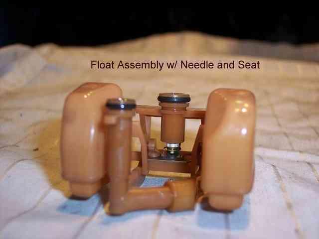
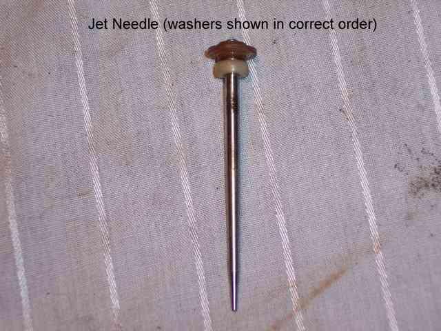
8 Pilot Screw setting U.S: Preset U.K: Preset (2 7/16 turns out) 1991 on U.K: Preset (2 1/2 turns out) Starter Jet (choke): 42.5 Float Height: 14.6mm (+/- 1mm) Understanding Clean Carburetors OK, so here's my guide on how to clean your Mikuni BST36SS carburetors a.k.a. Slingshot carbs. This guide is written assuming you already have the carburetors removed from your bike. Make sure you have a very clean workspace and have a box of ziplock bags on hand so when you remove parts from the carb, you can place them in a bag and label them. You should have one bag for each carb, and all the parts from the carb you're working on should stay in one bag, DO NOT mix them up. This is so that when you are all done re-assembling you carbs there are no extra bolts left over and you wont have to wonder..."where does this go again?" Front shot of Mikuni BST36SS carburetors


9 Back shot Bottom shot

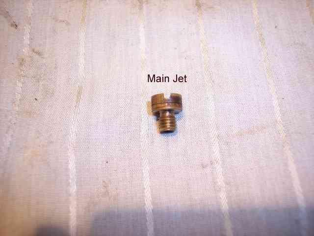
10 Top shot Everything needs to be clean, clean, clean. I cannot stress this enough. If the carbs are dirty on the outside when you take them off, spray them down with degreaser or some gentle parts cleaner. When you re-assemble the carbs make sure every part is extra clean, you don't want to be doing this over and over. Make sure your tools are clean too. Ive caught myself picking up a screwdriver that had dirt and metal shavings on the end of it whenineeded to put a main jet in. NOT GOOD! Fuel delivery system- (gas tank, petcock, fuel filters, and fuel line). All of these components of the fuel system need to be clean and in top shape or the bike will never run right. Sometimes its not even a carb problem, its a fuel problem. Check the tank to see if its rusty. If it is, either get a new tank or you can get the tank acid dipped to get most of the rust out. Some people use tank coatings like Kreem or Red-Kote. I know some have used it with good results butithink its just putting a band-aid on a broken elbow and might end up causing more problems than fixing. If the tank is rusty and you don't want to get a new tank or re-paint the one you have after getting it dipped id just try to clean it the best you can. The filters will catch the very small stuff, you just don't want so much rust that the filters get clogged. To clean the tank, empty out all of the gas and wash the small amount of remaining gas out with water. Remove the petcock and cover the hole with duct tape. Put an assortment of nuts, bolts, small chain, etc. into the tank and shake it back and forth, up and down, side to side to get any loose rust off of the inside of the tank. Now take the duct tape off, open the filler door and wash the loose rust out with water. Wash it a couple times to make sure you got it all. A garden hose works best. Allow the tank to dry so no water gets mixed with the new gas. Blowing compressed air into the tank will help speed up the drying process. Before you put the petcock back on, check the screen. If it is ripped, clogged or missing, replace the petcock. If the petcock is in good shape, re-install it and set the tank aside until you are finished with the carbs.
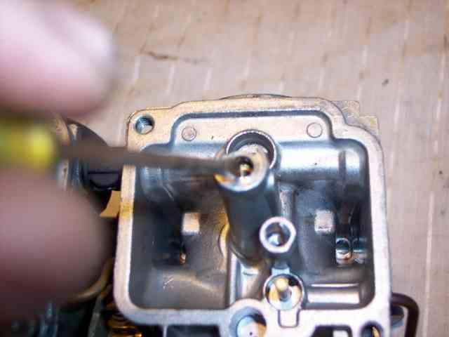
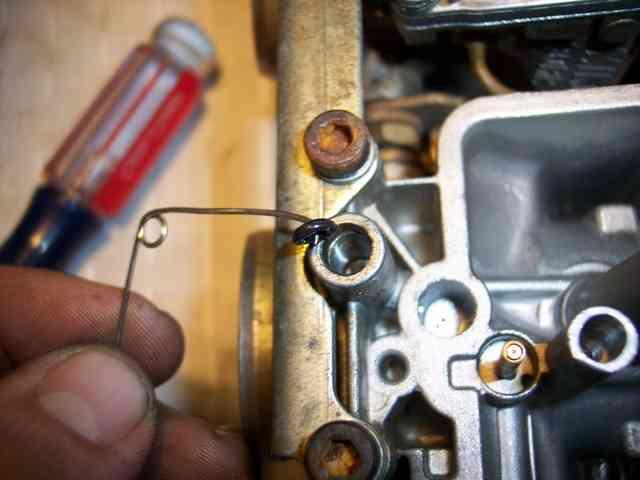
11 Another thing you should check while the carbs are off is the intake boots and clamps. Check for dry cracking/rotting/checking, rips, slices, gouges, etc. in the boots. Also check to make sure that the bolts that hold the boots to the motor are tight. If any air is leaking by the carbs into the motor it will not run right and you will be chasing your tail trying to tune the carbs with an intake leak. I know some GSX-R's have the synchronizing ports on the intake boots, make sure these are blocked off and not leaking also. Same thing with the clamps, make sure they're in good shape. If they aren't, get new ones and don't use a hose clamp! the hose clamp will cut into the intake boot and could cause a leak. TOOLS NEEDED: -Ziplock bags and permanent marker -Wide assortment of screwdrivers, regular and Phillips head. -Compressed air and blow-gun with small tip -Soaking tank for carbs/jets -Carb cleaner( both solvent and a can of cleaner with extension tip) or Carb cleaner "dip" -Vernier calipers ($20.00 at sears) -Drill and assorted drill bits -Cleaning tools- assorted small picks, torch cleaning tips, toothbrush, small wire brush (for heavy cleaning) DISASSEMBLY- First thing to do is remove the vent lines and fuel lines, this will make it easier to work on. I like to remove the big center idle adjustment screw also because then the carbs will stand up by themselves but some people may not want to. Next thing you will want to do while the carbs are still sealed is take the pilot screw plugs out.(refer to the pic for location) Underneath these plugs are the pilot screws or a.k.a idle screws. When you hear people talk about drilling out the idle screw plugs when they install a jet kit, this is what they're talking about. Well, whether you have a jet kit or not,irecommend taking the plugs out so that you can take the pilot screw out and inspect it. This will also let you to clean out the idle circuit. You will want to use a drill bit that is a couple sizes smaller than the plug. This way if you aren't holding the drill perfectly straight you wont drill into the carb body. Best thing to use is a drill press where you can control the feed but a hand held electric drill will work just as well if you are careful. Drill the plug out LIGHTLY, if you use too much pressure you will break thru the plug and drill the head of the pilot screw. NOT GOOD! Once you feel the drill bit break thru the plug, STOP and remove the drill. Sometimes the plug will come out with the drill bit. If it doesn't, get a flat tip screwdriver that fits halfway into the plug and while pushing down lightly, twist the screwdriver back and forth. The plug should come unseated from the carb and come right out. Repeat this on the remaining 3 carbs. After all plugs are out, use compressed air to blow all the shaving off of the carbs.

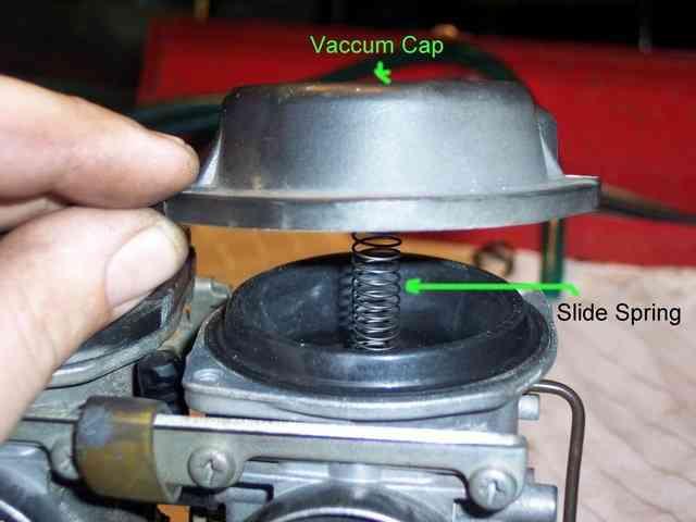
12 After all of that clutter is out of the way you will want to remove the black vacuum caps located on top of the carbs. NOTE: You should know, underneath the cap is a small o-ring that seals the synchronizing port. These are easy to loose so be prepared to catch it when you take the caps off. Check the rubber cap that seals the synchronizing port off. These will dry crack and will let air leak in and the bike will not run right. These are cheap, even if they look OK, id replace them. Once you have the cap unbolted remove it and put it in a labeled bag. Remove the diaphragm spring next, sometimes it will come out with the cap and sometimes it will stay in the carb, remove it and put it in the bag. Next, remove the diaphragm/slide/ needle assembly. Once it is out, hold the slide in one hand and tip it upside down into the other hand and the needle should fall out. Check the needle to see what condition its in. If its worn badly, you might want to get some new ones*. After that, bag the needle and slide and proceed to do these steps over again to the remaining carbs *Check this webpage from Factory Pro to see damaged jet needles. Use their guide to determine whether you need to replace your needles or not.
13

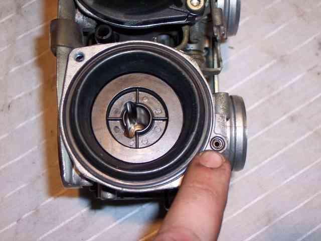
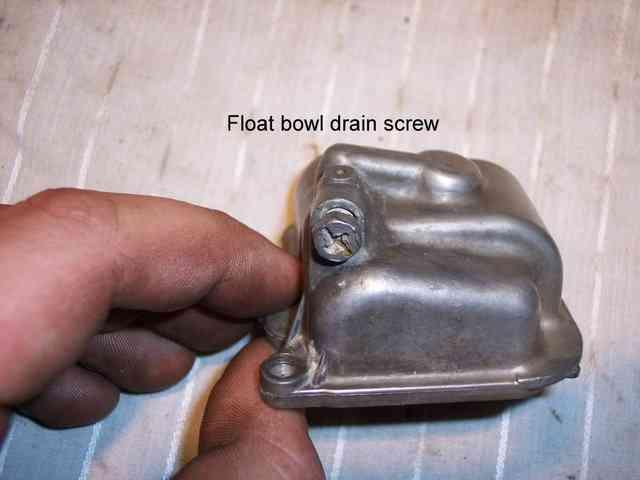
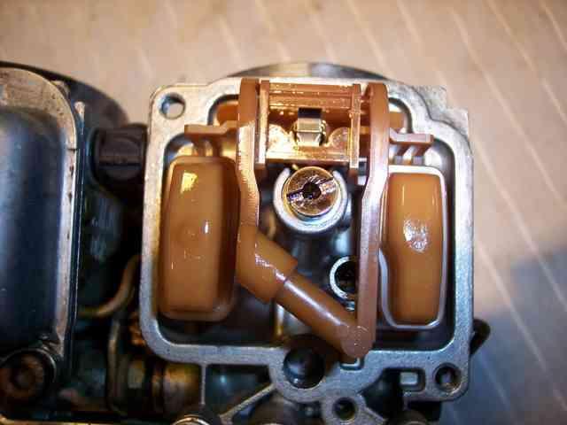
14 *You should use both hands to pick up the diaphragm. I only used one hand becauseihad to use the other to run the camera. Next is to remove the float bowls*. Make sure to remember which way the float drain screw is facing on each carb before you take them off. Now, remove the needle/float assembly. Gently pry under the tab near the needle with a small screwdriver while pulling up on the other side. Once it is out check the two o-rings to see what shape they are in. I highly recommend replacing these now. You already have them apart and if they do leak the bike will not run right. Another thing to check is if the needle and seat are working good. Clean off the fuel inlet part of the float good so there is no gas. Then blow thru the inlet with your mouth and manually work the float by hand. You should be able to blow thru it fine with the float all the way down. You should not be able to blow thru it with the float all the way up. If you feel air leaking by with the float all the way up, the float assembly is no good and needs to be replaced. Another thing to look for with the float assembly (this is rarer with plastic floats but I'll mention it anyways), if you have one cylinder that keeps getting flooded and the needle and seat and o-rings are good, the float may have a hole in it. What happens is, gas will leak into the hollow float and the float will not float anymore (haha), which will cause the needle to stay open and let fuel in all the time. Hold the float assembly up to a bright light and you should be able to see gas inside the float. Another good check is to hold the float under water and see if any air bubbles come out. You cannot replace the needle and seat or float by themselves. It comes as one assembly. If the float assembly is in good shape, bag it.
15
16

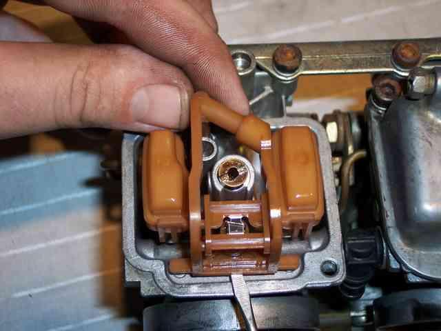
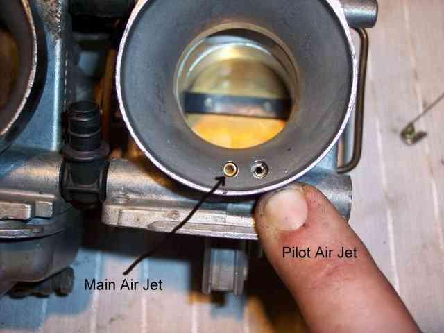
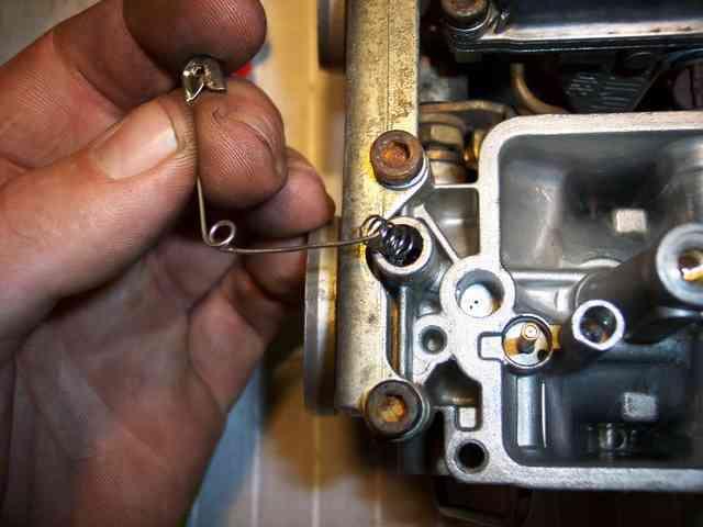
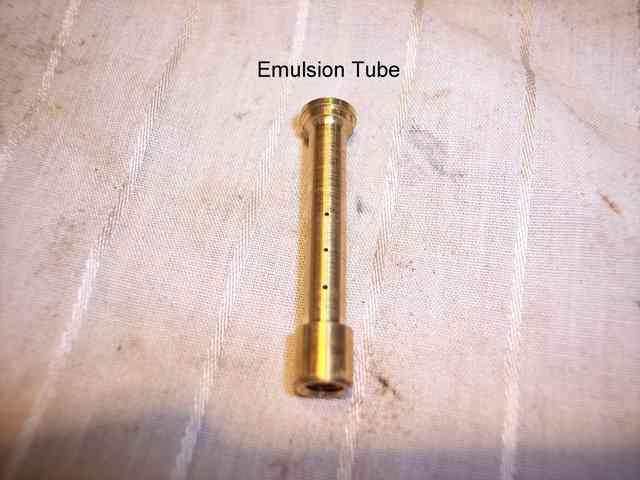
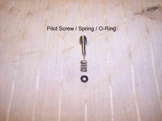
17 Next, remove the main jet with a good size flat screwdriver and start a separate bag for just jets. These will be getting soaked and cleaned later. Now remove the emulsion tube which is right under the main jet. In the pics you can see I used a small flat screwdriver to knock it out. This is all I had at the time. Best thing to use is a long 5mm bolt/screw. It will screw right into the emulsion tube and you can push/tap the emulsion tube out. This way you won't mar the soft threads of the tube, if you plan on using them over again. If you know you're going to put new tubes in anyway, just use whatever works. When the tubes come out, the plastic slide guide that holds the slide in place usually comes with it. This is fine, just notice that there is a o-ring on the bottom (see pic). Sometimes it stays on the guide, sometimes it stays on the carb itself. Whichever, push the emulsion tube up and out of the plastic body (you may have to wiggle it out). Put the guide in a bag and put the emulsion tube in your jets bag*. Next remove the pilot jet, it is right next to the main jet tower. Put this in your jets bag. Now remove the pilot air jet, located at the mouth of the carbs (see pic) put in the jets bag. The main air jet is pressed into the carb body and is not removable (at least the ones I have aren't). Do not attempt to remove this jet, just spray carb cleaner through it and blow it out. Last but not least, is the pilot screw. Underneath the screw is a spring and o- ring (by what I've been told there should be a small washer between the spring and o-ring to protect the o-ring from being ripped. I did not see these on my carbs, but keep a good eye out for the washer when you take everything out!) A small safety pin with a bent end on it will help you get both out. Be careful not to puncture the o-ring with your pick. Continue to disassemble the last 3 carbs in the same way. *Before you put the emulsion tubes away, take a second to see if they're worn out. Worn emulsion tubes can cause many problems, bad gas mileage, running rich, low power, etc. Take a look at these worn emulsion tubes on Factory Pro's site -

18

19
20
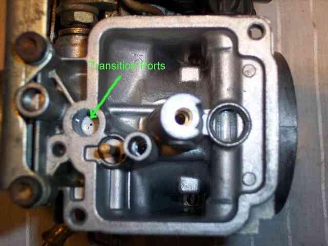
21 CLEANING Note: Most carb solvents like this are acid based and will eat plastic and rubber, make sure you look on the back of the carb cleaner to see if it's safe for plastic/rubber parts. If the dip is not plastic safe you will have to completely disassemble the rack of carbs and remove the rubber vent barbs and the rubber fuel inlet barbs. If your carbs are in very bad shape this is the routeirecommend. If you're a beginner and your carbs are in need of a full disassembly in order to soak them, please take them to a professional. Other than that, a can of spray carb cleaner will work fine. Now that the carbs are completely disassembled you will need to make sure that the insides of the carbs and all the fuel/air circuits are clean from dirt, varnish, sediment, or any other foreign objects. You can do this by one of two ways. One way is to go to the local auto store and buy some carb cleaner "dip" to soak the carbs in. This dip usually comes in a 5 gallon or more can. Pretty much just open the can and set the carbs in, let them soak until all the nasty gunk is gone. If using the spray carb cleaner, if there is any gunk inside of the float bowls or the inside of the carbs this should be cleaned out first. Spray some carb cleaner on the gunk to loosen it up and then use whatever cleaning tools you have to remove it. The inside of the carbs/float bowls should be very clean. Take as much time as you need to get them perfect. Next, take your can of carb cleaner with the nozzle extension and spray cleaner into every hole/circuit that you can find. Some of the circuits that you might not see that need to be cleaned are right by the throttle plate. These are called transition ports. Start by spraying some cleaner into whatever circuit you are trying to clean, let it soak for a second and then blow some compressed air in to try and clean it out. If its clean you will hear/feel air coming out of the other side of the circuit. This will let you know that circuit is clean. If you do not feel any air coming out, that circuit might be plugged. Try cleaning it with some more carb clean and blowing it out a couple more times. If none of this helps you will have to find a small piece of wire to stick in to break up whatever is blocking it. If you have a good supply of compressed air you should rarely have to resort to using the wire trick. Repeat these steps on every other hole/circuit you find. Now that the carbs are done, you can clean out the jets that you put aside. If you put the jets up to a light and look thru them you can tell if they're blocked or not. If they're really dirty you can soak these in the carb dip without any worry. If they look to be in decent shape, give them a quick look under a magnifying glass to see if there is any varnish build up on the inside of the jet. If it looks clean, or there is a small amount of varnish/gunk, give it a quick spray with the cleaner and blow it out with the compressed air. If your emulsion tubes are in good shape and you've decided to use them over, look in all of the air holes to see if they're plugged. Again, holding the tube up to a bright light will let you see if these small holes are blocked. If they are, use your torch cleaning tips to clean them. Do not force any kind of tip or pick into the hole, as you might enlarge it.
22

23 REASSEMBLY- Now that all the carbs and jets are clean, you can put them all back together. Its pretty much the reverse of taking it apart but theres some things to know. *When putting the vacuum caps or float bowls back oniwould recommend replacing the Phillips head screws with socket cap screws, especially if you're putting a jet kit in. If you have the carbs apart multiple times to change the settings, the head of the screw usually strips out. The size of the screw to replace them is 8mm x Go to your local hardware store and get some stainless steel screws and lock washers. If all they have is regular steel thats OK, but they will rust as you can see mine did in the pics. You should only need lock washers for the float bowls. Remember to take the screw with you so you can get the correct length. Order of re-assembly (read all information below before re-assembly): 1. Plastic guide for slide and emulsion tube 2. Jets (install main jet first to hold emulsion tube in) then all other jets 3. Needle/slide/diaphragm assembly 4. Slide spring 5. Vacuum caps 6. Float assemblies (then set float height) 7. Float bowls 8. Re-install carbs on bike
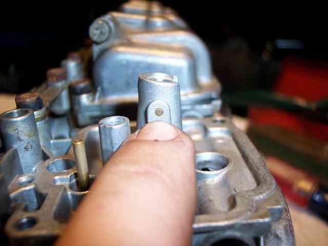
24 Plastic guide/emulsion tubes - When putting the emulsion tubes back in, there is only one way they can go back in. If you look at the bottom of the tube ( in the pictures )you can see a slot. Now look at the main jet tower on the carb, see that pin? ( I'm pointing to it in the pics ) This is where the slot in the tube needs to line up. If the tube doesn't go in easily (might have to lightly tap them in) then the tube is probably not lined up right. Make sure when installing the slide guide block the o-ring is centered and not off to one side. Needle/Slide/Diaphragm assembly - The needle and washers go in the order shown in the picture, the white washer that goes on bottom has two notches cut into it. These notches face down. Vacuum caps and slide springs - Make sure the o-rings are in place before you install the vacuum cap. If not there will be a vacuum leak and the bike will not run right. When installing the vacuum cap, put the slide spring onto the tower in the cap and then lower both onto the carb. If you put the spring in the carb first and then lower the cap onto the spring, it might not seat correctly and may come off the tower. After you have all the caps on, manually work the slide with your finger, it should slide up and down with some resistance. If it slides up easily, or doesn't feel right, the spring may have popped off the cap. Take the cap off again and double check everything. Pilot screws/jets - As you can see in the pic, the o-ring goes first, then spring, then the screw. Screw the pilot screw in until you feel it bottom out on the carb. Do not tighten the pilot screw anymore after it has bottomed out! You may damage the screw or could damage the carb. Now back the screw out however many turns that are factory recommended. If you have added a performance exhaust or air filter you may need to turn the screw out farther to richen up the idle mixture. The more you back out the pilot screw (counter-clockwise) the richer the idle mix. The more it is screwed in (clockwise), the leaner the idle mixture. The pilot air jets that screw into the mouth of the carb (airbox side) are easy to cross thread so just be careful. Float - Once all the jets are in, its time to put the float on. I put some clean motor oil on my finger and lightly coat the o-rings. The oil will help the float "snap" into place and will prevent you from breaking the float from forcing it into place. The 0-rings are what holds the float assembly to the carb. It is an interference fit. After putting the float assembly on, lightly pull up on each end of the float where the o- rings hold it. If you can easily pull the float back off the carb, the o-rings are no good and need to be replaced. Setting Float Height - Now that the carbs are pretty much all back together and the float assemblies are on you need to set float height. The carbs should be leaning at an angle so that the float tang (metal tab that rides on the needle) is touching the needle but not compressing it. I myself pick the float up off the needle and then set it down gently to make sure the needle wasn't compressed to begin with. Now you need to know what the float height spec is. You can refer to the specs in the beginning of this sticky or look in your repair manual. The spec will be in millimeters. If using vernier calipers you will need to convert millimeters to inches. You can use this webpage to do your conversion, To adjust the float height you will need to bend the float tang either up or down. The float tang is the piece of metal that the needle clips to on the float assembly. Bending it up will decrease the float height, bending it down will have the opposite affect.

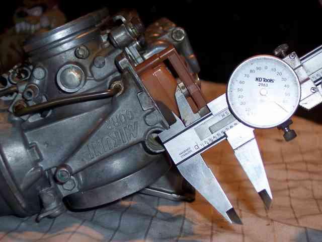
25 One thing to mention thatihave seen is that not all float tanks are the same height. WhatImean by this is on one float assembly, one float tank may be higher than the other one. When setting float height you will want to set it on the float tank that is highest. I should have taken a picture to demonstrate this butididn't think of it until afterihad the carbs back on my bike. NOTE- Its called setting the float height but your actually setting the fuel level. Picture the carbs installed on the bike, the higher the float is, the higher the fuel level is in the bowl. The higher the fuel level the richer the air/fuel mix. The lower the fuel level, the leaner the air/fuel mix. The reason for this is, the closer the fuel is to the venturi (emulsion tube and needle) the easier it is for the vacuum to pick up the fuel. The farther away the fuel is, the more vacuum (higher rpm) you will need to pick up the fuel. Some float heights converted: 13mm = = mm = mm = mm = mm = mm =.0669 You don't need to use a set of calipers, just as long as you measure from the base of the carb where the float bowl gasket sits to the very top of the float bowl with some type of measuring device. (As shown in picture)
26
27

28 Bench Sync Tip Best way to bench sync is with a pair of vernier calipers. Wire the throttle wide open someway on the carbs. Then measure with your calipers from the bottom of the throttle blade to the lowest part of the throttle bore. Measure the stationary carb first then set the other carbs to that one carbs measurement. Ill post pics sometime, I don't think im saying it in the best way. -Rob Additional Pictures Here are some pictures I had left over that might be of some use. Shot of the slide from the bottom, the middle hole is where the needle goes, the two outer holes are where the air flows out to raise the slide. These are the holes you would drill/plug/modify on some jet kits.


29 Side shot of the slide. The shape of the bottom of the slide is where the carbs get the "slingshot" term. Intake for the diaphragm.
30

31 Copyright Gixxer.com

32 Just for grins and giggles, here are a couple of pictures of some pretty nice GS850s. - BassCliff

33
Radiator Coolant Flush
 Radiator Coolant Flush Should be done every couple years. Fairly easy job, need a Phillips head screwdriver, 10mm deep socket, couple gallons of water, a gallon of silicate free anti-freeze, needle nose
SKS FIELD STRIPPING 101,CORROSIVE AMMO CLEANING,LUBRICATION
 SKS FIELD STRIPPING 101,CORROSIVE AMMO CLEANING,LUBRICATION We all know that the SKS gain more and more popularity everyday so i was thinking why not make a little SKS field stripping tutorial I know most
JOHN DEERE GATOR HPX/XUV 2 PASSENGER HEATER INSTALLATION INSTRUCTIONS (p/n: 9PH20S30)
") P. 1 of 12 JOHN DEERE GATOR HPX/XUV 2 PASSENGER HEATER INSTALLATION INSTRUCTIONS (p/n: 9PH20S30) Item: Qty: Description: 1 2 1 x 1 x 5/8 Tee Fitting 2 2 Plastic Snap-in Hose Grommet 3 4 1-1/2" Hose Clamps
P. 1 of 12 JOHN DEERE GATOR HPX/XUV 2 PASSENGER HEATER INSTALLATION INSTRUCTIONS (p/n: 9PH20S30) Item: Qty: Description: 1 2 1 x 1 x 5/8 Tee Fitting 2 2 Plastic Snap-in Hose Grommet 3 4 1-1/2" Hose Clamps
BMW E36 Thermostat Removal And Coolant Flush
 BMW E36 Thermostat Removal And Coolant Flush Disclaimer: The cooling system is critical to the proper operation of your car. Failure to properly install all of the components of the cooling system could
Oreck Edge - Upright Tune-Up & Service Guide 02/26/2010
 The Oreck Manufacturing Company Oreck Edge - Upright Tune-Up & Service Guide 02/26/2010 Compiled by Clark DeNoble 1 Table of Contents Electrical Page 3 Tune-Up Evaluate Page 4 Clean Page 4 Replace Page
Table of Contents. What to Expect with. Mounting Options. Tools Needed
 Table of Contents www.hunterfan.com What to Expect with Your Installation Congratulations on purchasing your new Hunter ceiling fan! It will provide comfort and performance in your home or office for many
N54 Silicone Intake install tips
 N54 Silicone Intake install tips Thank you for your purchase of the VTT BMW N54 Silicone Intake set! First thing to do when you open your box is to make sure all parts are in their respective bags and
SuperKlean Washdown Products
 February 2012 DURAMIX 8000 INSTALLATION AND MAINTENANCE INSTRUCTIONS **DO NOT THROW AWAY AFTER INSTALLATION** **SAVE AND DISPLAY PROMINENTLY WHERE THIS EQUIPMENT IS USED** WARNING HIGH PRESSURE AND HOT
Bliss Box Former Troubleshooting. 6.1 Troubleshooting Chart. Troubleshooting INTRODUCTION SAFETY PROCEDURES
 6.0 Bliss Box Former 1.0 INTRODUCTION Table 6-1 provides a logical sequence of tests that are designed to isolate problems with the Bliss Box Former machines. This table includes a list of probable causes
Table of Contents. What to Expect with. Tools Needed. Mounting Options. Blades
 www.hunterfan.com Table of Contents Ceiling Bracket 30 inches Downrod Ladder 3 Wiring Operation, Maintenance & Cleaning Light Kit 11 Troubleshooting??? 16 15 1 12 10 9 5 Blades Canopy 6 4 PÁGINA 2 7 feet
Table of Contents. What to Expect with. Tools Needed. Mounting Options. Blades
 Table of Contents 1.888.830.1326 Ceiling Bracket 30 inches Ladder Downrod 3 Wiring 10 Operation, Maintenance & Cleaning Light Kit 11 Troubleshooting??? 17 15 1 13 5 Blades 9 Switch Housing 12 Canopy 6
Changing Radiator Pt1
 Changing Radiator Pt1 I dont know if any of you owners of a year 2000 (W Reg) Phase 3 (with air-con) have attempted to change your radiator (the type with the thin clip that secures the bottom hose) but,
IMAGE V. Parts and Service Manual
 IMAGE 0V Section II Parts and Service Manual (88B) CLARKE TECHNOLOGY Image Operator's Manual Page AUTHORIZED PERSONNEL MAINTENANCE To Access Pump Motor. Remove brush housing from machine. See "Brush Motor
Welcome! Today s topic: Small Home Repairs. November 14, 2015
 Welcome! Today s topic: Small Home Repairs November 14, 2015 Small Home Repairs Course Presented by Monique Johnson Environmental Green Solutions, LLC Objective Educate homeowners on basic technical skills
SUBCOURSE EDITION EN US ARMY ENGINEER SCHOOL PLUMBING FIXTURES (PLUMBING IV)
") SUBCOURSE EDITION EN5113 5 US ARMY ENGINEER SCHOOL PLUMBING FIXTURES (PLUMBING IV) US ARMY PLUMBER MOS 51K SKILL LEVELS 1 AND 2 COURSE PLUMBING FIXTURES (PLUMBING IV) SUBCOURSE NO. EN5113 US Army Engineer
SUBCOURSE EDITION EN5113 5 US ARMY ENGINEER SCHOOL PLUMBING FIXTURES (PLUMBING IV) US ARMY PLUMBER MOS 51K SKILL LEVELS 1 AND 2 COURSE PLUMBING FIXTURES (PLUMBING IV) SUBCOURSE NO. EN5113 US Army Engineer
GETZ EQUIPMENT INNOVATORS PART NO.: 9G58619 MODEL: SV1 150 PR VACUFILL SYSTEM (Revised 2/25/14)
") GETZ EQUIPMENT INNOVATORS PART NO.: 9G58619 MODEL: SV1 150 PR VACUFILL SYSTEM (Revised 2/25/14) !!WARNING!! SEVERE DAMAGE AND/OR INJURY MAY RESULT DO NOT DISCHARGE ANY EXTINGUISHER CYLINDER EXCEEDING 195
GETZ EQUIPMENT INNOVATORS PART NO.: 9G58619 MODEL: SV1 150 PR VACUFILL SYSTEM (Revised 2/25/14) !!WARNING!! SEVERE DAMAGE AND/OR INJURY MAY RESULT DO NOT DISCHARGE ANY EXTINGUISHER CYLINDER EXCEEDING 195
Model HD 3000 Part No High Pressure Washer Operator Manual
 Model HD 3000 Part No. 1.187-116 High Pressure Washer Operator Manual Overview..................................1 P recautions...............................1-2 Assembly Instructions.........................3
π H-2268 SANITAIRE UPRIGHT VACUUM SAFETY uline.com
 π H-2268 SANITAIRE UPRIGHT VACUUM 1-800-295-5510 uline.com SAFETY PAGE 1 OF 7 NOTE: When using an electrical appliance, basic precautions should always be followed, including the following: READ ALL INSTRUCTIONS
Standard Downrod for ceilings 8-10 feet high. Longer Downrod for ceilings 10 feet or higher
 Table of Contents www.casablancafanco.com To register your fan, please visit: www.casablancafanco.com/register What to Expect with Your Installation Save your receipt for proof of purchase. Ceiling Bracket??
Instructions for Installing the MMD Rear Window Louvers
 Instructions for Installing the MMD Rear Window Louvers Time Required: Less than 1 hour of labor (5 hours total installation if the 4 hours of letting the brackets set are included). Required Tools: Socket
Table of Contents What to Expect with Your Installation. Top Housing. Ceiling Plate. Tools Needed.
 Table of Contents Congratulations on purchasing your new Hunter ceiling fan! It will provide comfort and performance in your home or office for many years. This installation and operation manual contains
Fun with the Ventilation System
 Not long after I got my 33, I was foolish and inexperienced in the ways of Alfas. So when I noticed squealing noises from the ventilation fan motor and miserable airflow out of the air vents, I decided
Model HD 3501 Part No High Pressure Washer Operator Manual
 0 15 25 40 25 Nozzle Identification SOAP HD3501 Manual 4/22/02 6:57 PM Page 1 Model HD 3501 Part No. 1.810-999.0 High Pressure Washer Operator Manual Overview..................................1 Precautions...............................1-2
PackardInfo.com. HOW TO: Rebuild a Trico Mag Nu Matic Vacuum Washer Pump. Introduction
 Introduction So here hopefully ends the saga of my Trico Mag Nu Matic washer pump. I found the pump at the 2009 Packards International swap meet for $35. I thought I had the deal of a lifetime as it looked
Click here for a labelled version of above
 Click here for a labelled version of above Download Of This Page: Click Here to download this whole page. (773 Kb Adobe Acrobat File) Biodiesel Processor Diagram: Click Here to download a detailed diagram
GETZ MANUFACTURING PART NO.: MODEL: SV1 100 PR VACUFILL SYSTEM (Revised 6/7/05)
") GETZ MANUFACTURING PART NO.: 58616 MODEL: SV1 100 PR VACUFILL SYSTEM (Revised 6/7/05) GETZ SV1-100-PR VACU-FILL SYSTEM TABLE OF CONTENTS PAGE # 1... GETZ SV1-100-PR VACU-FILL SYSTEM 2... PARTS LIST 3...
GETZ MANUFACTURING PART NO.: 58616 MODEL: SV1 100 PR VACUFILL SYSTEM (Revised 6/7/05) GETZ SV1-100-PR VACU-FILL SYSTEM TABLE OF CONTENTS PAGE # 1... GETZ SV1-100-PR VACU-FILL SYSTEM 2... PARTS LIST 3...
High Pressure Washer Operator Manual. Specifications Model HD 2700 DH/DB
 Model HD 2700 DB Part No. 1.194-116 Model HD 2700 DH Part No. 1.194-117 Model HD 3000 DH Part No. 1.187-115 Model HD 3500 DH Part No. 1.810-997 Model HD 3500 DB Part No. 1.810-998 High Pressure Washer
Fast Fix Kenmore Model 100 Clutch Replacement
 Fast Fix Kenmore Model 100 Clutch Replacement Replace your worn or broken transmission clutch on the Kenmore Model 110 washing machine. Written By: Jonathan Beach ifixit CC BY-NC-SA www.ifixit.com Page
Heat Exchanger Block Replacement Instructions
 Series 1-4 Gas-fired water boiler Heat Exchanger Block Replacement Instructions Ultra-80 S1-4 Heat Exchanger Block Replacement Kit, Part No. 383-500-773 Ultra-105 S1-4 Heat Exchanger Block Replacement
Model K 3000 G Part No
 K3000G Manual 11/30/01 4:56 PM Page 1 Model K 3000 G Part No. 1.133-110.0 High Pressure Washer Operator Manual Overview..................................1 Precautions...............................1-2
Parts List. RevA _85609INST
 Parts List (1) Air Oil Separator (1) Billet Clamp (1) Stainless Steel Mount (1) Stainless Steel Tab (1) 90 degree barbed fitting (1) Straight Barbed Fitting (2) 30 Long ½ I.D. Hose (4) ¼ x 20 x 5/8 SHCS
INSTANT HOT WATER DISPENSER
 INSTANT HOT WATER DISPENSER Tank Installation Materials required (not provided) 2 mounting bracket screws (and 2 plastic anchors if attaching to drywall) Shut-Off valve and T fitting Components When you
Model K 5800 G Part No
 K5800G Manual 11/30/01 5:02 PM Page 1 Model K 5800 G Part No. 1.194-103.0 High Pressure Washer Operator Manual Overview..................................1 Precautions...............................1-2
Model K 4400 G Part No High Pressure Washer
 Model K 4400 G Part No. 1.133-208.0 High Pressure Washer Table of Contents Overview..................................1 Precautions...............................1-2 Assembly Instructions.........................3
How to Fix a Leaky Toilet:
 How to Fix a Leaky Toilet: First, determine the type of toilet you have. Pressurized Toilet: Inside this toilet is a sealed tank. When water is fed from the water line, the air inside the tank is compressed.
Table of Contents. Ceiling Bracket Installation
 Table of Contents What to Expect with Your Installation Congratulations on purchasing your new Casablanca ceiling fan! It will provide comfort and performance in your home or office for many years. This
Owner s Guide and Installation Manual
 For Your Records and Warranty Assistance For reference, also attach your receipt or a copy of your receipt to the manual. Model Name Type 8 Models Owner s Guide and Installation Manual Model No. Catalog
This site is based on a but applies to all 1971-on Saab 99 and Saab 900.
 by Mark Jeter updated: December 8, 2004 originally web-published June 27, 2001 This document shows how the original waterpump in a Saab "B" engine can be eliminated and replaced with a reliable, efficient
pushing the tube into the rear of the water outlet housing with a slight twisting motion to evenly distribute the adhesive. After cleaning off any ext
 I chose an original FE expansion tank that had the filler neck on the driver's side of the tank but still had the radiator hose outlet facing the passenger side. I figured using such a tank would afford
SAAB 99 Series H Type Engine. Installation Guide Silicone Cooling System Hoses. Classic Silicone Hoses
 SAAB 99 Series 1981 1984 H Type Engine Installation Guide Silicone Cooling System Hoses Classic Silicone Hoses http://www.classicsiliconehoses.com/ Disclaimer This document is for reference purposes only.
Table of Contents. What to Expect with. Mounting Options. Tools Needed
 www.hunterfan.com Table of Contents What to Expect with Your Installation Congratulations on purchasing your new Hunter ceiling fan! It will provide comfort and performance in your home or office for many
INSTRUCTIONS FOR USE PORTABLE VACUUM SYSTEM LEI Part # s / , , , IMPORTANT INFORMATION
 INSTRUCTIONS FOR USE PORTABLE VACUUM SYSTEM LEI Part # s / 27-009, 27-010, 27-015, 27-020 IMPORTANT INFORMATION UNATHORIZED CHANGES OR ALTERATIONS TO ANY LINCOLN PORTABLE VACUUM SYSTEM WILL AUTOMATICALLY
installation and operation manual for Hunter Ceiling Fans
 For Your Records and Warranty Assistance Model Name: Catalog/Model No.: Serial No.: Date Purchased: Where Purchased: For reference also attach your receipt or a copy of your receipt to the manual. installation
Owner s Guide and Installation Manual
 For Your Records and Warranty Assistance For reference, also attach your receipt or a copy of your receipt to the manual. Model Name Type 2 Models Owner s Guide and Installation Manual Model No. Date Purchased
General System Layout Sketch
 General System Layout Sketch EZ-37 Solar Panels PV panel Can use Standard Copper, CPVC or PEX Pipes Pump Existing Water Heater Bottom Feed Connector 1 Introduction This document describes how to install
Wrangler JK Engine Cooling
 Wrangler JK Engine Cooling Preface In the old days the temperature gauge was a simple and direct monitor of engine cooling. Contemporary cars with their recovery tanks, electric fans, and electronic controls
Bob-White Systems: AUTOMATED BOTTLE FILLER
 Bob-White Systems: AUTOMATED BOTTLE FILLER PRODUCT CAPPER MANUAL General Safety Rules WARNING: READ ALL INSTRUCTIONS. Failure to follow the safety rules listed below and other basic safety precautions
Safety. Rinse Kit for Multi-Pro 1200 and 1250 Turf Sprayers Model No Safety and Instructional Decals. Installation Instructions
 Rinse Kit for Multi-Pro 1200 and 1250 Turf Sprayers Model No. 106-4842 Form No. 3353-529 Rev B Installation Instructions Note: Determine the left and right sides of the machine from the normal operating
PIPE DREAMS 96. Aeroponic Garden IMPORTANT:
 1 WARNING: BEFORE PUTTING WATER PUMP INTO OPERATION FILL UP NUTRIENT TANK TO TOP OF PUMP. THE PUMP MUST NEVER RUN DRY OTHERWISE, WARRANTY WILL BE DECLINED. READ FILLING INSTRUCTIONS BEFORE USE. Welcome
PolyMax H1-10 Dutch Bucket System
 112529 PolyMax H1-10 Dutch Bucket System *Actual system may differ. PolyMax Dutch Buckets Versatile PolyMax Dutch Buckets are ideal for both small- and large-scale hydroponic growing. STK# DIMENSIONS 112529
Built-in Gas Hob CZ55554 CZ55571
 Built-in Gas Hob CZ55554 CZ55571 INSTALLATION AND OPERATING INSTRUCTIONS The product may differ from the one illustrated but the installation and operation procedure remains the same The product may differ
CapraLite. Owner s Manual. Milking Machines. Built by: Apparatus Mfg., Inc. 13 Commerce St Poughkeepsie, NY 12603
 CapraLite Milking Machines Owner s Manual www.capralite.com Built by: Apparatus Mfg., Inc. 13 Commerce St Poughkeepsie, NY 12603 Page 2 Getting your Machine ready Your machine is almost ready to use. For
Operating Instructions for the BBO-1 and BBO-2 Basket Blasters
 Operating Instructions for the BBO-1 and BBO-2 Basket Blasters 2101 West Cabot Boulevard Langhorne, PA 19047-1893 www.empire-airblast.com Page 2 Model Number: Serial Number: Date of Purchase: Date of Installation:
INSTALLATION INSTRUCTIONS UNDERCOUNTER DISHWASHERS
 INSTALLATION INSTRUCTIONS UNDERCOUNTER DISHWASHERS VIKING 111 Front Street Greenwood, Mississippi 38930 USA (662) 455-1200 IMPORTANT - PLEASE READ AND FOLLOW Before beginning - please read these instructions
Table of Contents. What to Expect with. Mounting Options. Tools Needed. Preparation. Wiring. Downrod.
 Table of Contents www.casablancafanco.com What to Expect with Your Installation Congratulations on purchasing your new Casablanca ceiling fan! It will provide comfort and performance in your home or office
Table of Contents What to Expect with Your Installation. Tools Needed. Wall Control
 Table of Contents Congratulations on purchasing your new Casablanca ceiling fan! It will provide comfort and performance in your home or office for many years. This installation and operation manual contains
C-IV 60 CEILING FAN READ AND SAVE THESE INSTRUCTIONS. FAN RATING AC 120V. 60Hz
 C-IV 60 CEILING FAN READ AND SAVE THESE INSTRUCTIONS FAN RATING AC 120V. 60Hz Please do not use any electric or battery powered tools in the assembly and installation of this or any Matthews Fan Company
Table of Contents. What to Expect with. Tools Needed. Mounting Options. Preparation. Downrod. Maintenance.
 www.hunterfan.com Table of Contents What to Expect with Your Installation Congratulations on purchasing your new Hunter ceiling fan! It will provide comfort and performance in your home or ofice for many
Table of Contents. What to Expect with. Mounting Options. Tools Needed. Wall Control
 Table of Contents www.casablancafanco.com What to Expect with Your Installation Congratulations on purchasing your new Casablanca ceiling fan! It will provide comfort and performance in your home or office
Table of Contents. 1 M /10/14 Casablanca Fan Company. What to Expect with Tools Needed.
 www.casablancafanco.com Table of Contents Congratulations on purchasing your new Casablanca ceiling fan! It will provide comfort and performance in your home or ofice for many years. This installation
===================== LandyAir - Disco 3/4 &RR Sport
 ! Dear Customer please choose a part of this document that is particular to the product you purchased. Disclaimer This document is the property of Landyair and should not be redistributed or replicated
Pro-MAX Ultraviolet Sterilizer
 Pro-MAX Ultraviolet Sterilizer Lifegard Aquatics introduces the Pro-MAX UV Sterilizer, featuring a patent-pending, flow-through design with less restrictive angled inlet and outlet ports requiring less
Fume Free Casting Box
 Fume Free Casting Box Contributed by: Mark James A.K.A mark james This tutorial was downloaded from http://www.penturners.org The International Association of Penturners - 2014 FUME FREE CASTING BOX by
Table of Contents What to Expect with Your Installation. Tools Needed. Wall Control
 Table of Contents Congratulations on purchasing your new Casablanca ceiling fan! It will provide comfort and performance in your home or office for many years. This installation and operation manual contains
Series 8920, 9200, 9300, 9400 Service Center Guide
 Series 8920, 9200, 9300, 9400 Service Center Guide 2005 BISSELL Homecare, Inc. Page 1 of 22 TABLE OF CONTENTS Product overview Page 3 Quick reference troubleshooting chart Page 4 UL recommended high voltage
Installation Instructions. For the 18 Built-In Dishwasher and Front Color Panels
 Installation Instructions For the 18 Built-In Dishwasher and Front Color Panels Printed in USA 154232102 Before You Begin DO NOT INSTALL DISHWASHER UNTIL YOU HAVE READ ALL INSTRUCTIONS. FOR YOUR SAFETY,
Adding a Cooling Fan to The Big Red Pig (BRP)
") Adding a Cooling Fan to The Big Red Pig (BRP) As many XR650R owners are aware, the bike comes from the factory very restricted in terms of jetting and airflow. This needs to be corrected both for proper
Adding a Cooling Fan to The Big Red Pig (BRP) As many XR650R owners are aware, the bike comes from the factory very restricted in terms of jetting and airflow. This needs to be corrected both for proper
OWNER S MANUAL AND INSTALLATION GUIDE PLEASE READ THIS MANUAL CAREFULLY BEFORE ATTEMPTING INSTALLATION
 ClearChoice Economy Under Sink Drinking Water System OWNER S MANUAL AND INSTALLATION GUIDE PLEASE READ THIS MANUAL CAREFULLY BEFORE ATTEMPTING INSTALLATION Congratulations on the purchase of your ClearChoice
Installation and Operation Manual For Hunter Ceiling Fans
 Installation and Operation Manual For Hunter Ceiling Fans 1 2 CONGRATULATIONS! Your new Hunter ceiling fan is an addition to your home or office that will provide comfort and performance for many years.
SAFETY AND OPERATING MANUAL
 SAFETY AND OPERATING MANUAL HOT WATER ELECTRIC WATER BLASTERS Read Safety & Operating Instructions Before Commencing Operation THESE INSTRUCTIONS MUST BE READ AND ADHERED TO BEFORE OPERATING THIS MACHINE.
Sanitise Syrup Lines & Valves. Taylor PH61 Cleaning every 14 days
 Taylor PH61 Cleaning every 14 days Drain the Syrup Lines Remove each syrup feed tube from syrup bottle and let excess syrup drain from the feed tube back into the syrup bottle. When flow of syrup from
CBT Bowl & wrap replacement
 CBT bowl & wrap replacement 2 CBT BOWL & WRAP REPLACEMENT Revision History rev. level 01_03.14.2012 rev. level 02_03.19.2012 rev. level 03_03.23.2012 rev. level 04_05.30.2013 NOTE: due to the fact that
Can Am Commander 1000 Radiator Relocation Installation Instructions
 Can Am Commander 1000 Radiator Relocation Installation Instructions What comes with the kit 2 CNC Machined Aluminum mounting brackets 2 pcs M6 x 1.0 x 60mm long SHCS 2 pcs M6 x 1.0 x75mm long SHCS 4 pc
Installation Instructions
 Suzuki Samurai Coolant and Water Hose Kit (SKU# SER-CHK) Installation Instructions SER-HHCK SER-WPI SER-ROP CAUTION: Safety glasses should be worn at all times when working with vehicles and related tools
Tap Master Artesian Hydro Gardener Series Installation & Service Manual
 Perfect Water Technologies 7 Tips for an Easy and Successful Installation 1. Keep it simple - there are 3 connections to make, and the tubing is color coded. 2. Have plenty of time, light, space, and towels
Smith's Heater Core DIY version
 Smith's Heater Core DIY version Some time ago there was an article in the LRO about how to make a new core for the old round Smith's heaters that involved wrapping a number of loops of 8mm diameter micro
Torrena 42 Ceiling Fan
 Torrena 42 Ceiling Fan Owner s Manual Part # 269268, 269269 Model # 32096, 32097 Exclusively Distributed by: HD Supply Facilities Maintenance, Ltd. Atlanta, GA 30339 2017 Made in China If you are experiencing
Milkweed Seed Separator
 Milkweed Seed Separator Chip Taylor s design is for a 30 gallon metal trashcan (plans and video http://monarchwatch.org/bringback-the-monarchs/milkweed/seed-separator). Bryan Bockbrader of the Wood County
HydroCycle Vertical Aeroponic Systems
 HydroCycle Vertical Aeroponic Systems 2018 Growers Supply All Rights Reserved. Reproduction is prohibited without permission. 113700 4' Vertical System (24 Grow Sites) Revision date: 01.10.18 1 Important
Camarillo 52 Ceiling Fan
 Owner s Manual Camarillo 52 Ceiling Fan Part # 269263, 269259, 269287 Model # 32091, 32092, 32087 Exclusively Distributed by: HD Supply Facilities Maintenance, Ltd. Atlanta, GA 30339 2017 Made in China
DAD-500 (130026) DESICCANT AIR DRYING SYSTEM
 DESICCANT AIR DRYING SYSTEM") SERVICE BULLETIN SB---O Replaces SB---N DAD-00 (00) DESICCANT AIR DRYING SYSTEM Air In 0 The CFM DAD-00 Desiccant Air Drying System is designed to be a point of use system. It is capable of removing dirt,
SERVICE BULLETIN SB---O Replaces SB---N DAD-00 (00) DESICCANT AIR DRYING SYSTEM Air In 0 The CFM DAD-00 Desiccant Air Drying System is designed to be a point of use system. It is capable of removing dirt,
Table of Contents. What to Expect with Your Installation. Tools Needed. Mounting Options. Ceiling Bracket. Wiring.
 www.hunterfan.com Table of Contents What to Expect with Your Installation Congratulations on purchasing your new Hunter ceiling fan! It will provide comfort and performance in your home or office for many
What to Expect with Your Installation. Tools Needed. 30 inches PA G E. To register your fan, please visit: 11 PA G E
 Table of Contents Tools Needed Mounting Options 1.888.227.2178 Ceiling Bracket 30 inches To register your fan, please visit: www.casablancafanco.com/register Wiring 11 Troubleshooting??? 15 14 1 13 Operation,
Eccotemp L5 and L10 Comprehensive Troubleshooting Guide
 http://waterheatertimer.org/tent-city-usa-water-heater.html Eccotemp L5 and L10 Comprehensive Listed below are some common questions and troubleshooting guidelines for our various models. Always remember
Model: Series. PumpAgents.com - buy pumps and parts online. DESIGNER STYLED MARINE TOILET With Integral Bowl Rinse Water/Waste Evacuation Pump
 PumpAgents.com - Click here for Pricing/Ordering Model: 37085-Series DESIGNER STYLED MARINE ILET With Integral Bowl Rinse Water/Waste Evacuation Pump FEATURES Single button flush actuator All toilet plumbing
installation and operation manual for Hunter Ceiling Fans
 For Your Records and Warranty Assistance Model Name: Catalog/Model No.: Serial No.: Date Purchased: Where Purchased: For reference also attach your receipt or a copy of your receipt to the manual. installation
BLAST-IT-ALL BUMPER BLASTER
 LARRY HESS AND ASSOCIATES, INC 185 PIPER LANE / SALISBURY, NC 28147 PHONE: 1-800-535-2612 / FAX: 1-704-638-9311 WWW.BLAST-IT-ALL.COM BLAST-IT-ALL BUMPER BLASTER SUCTION BLAST CABINET NOTE: It is the responsibility
1350 & AMMCO Brake Washer Systems. Installation and Operating Instructions With Safety and Maintenance Instructions and Parts Identification
 1350 & 1450 AMMCO Brake Washer Systems Installation and Operating Instructions With Safety and Maintenance Instructions and Parts Identification READ these instructions before placing unit in service.
Over-the-Range Microwave Oven Installation Instructions MVH130* MVH230* MVH330*
 Over-the-Range Microwave Oven Installation Instructions MVH130* MVH230* MVH330* * Additional alphanumeric characters representing other models in the series may follow each model number. Keep these instructions
SHOT BLAST CABINET USER INSTRUCTIONS. Model No: CSB20B. Part No: GC05/13
 SHOT BLAST CABINET Model No: CSB20B Part No: 7640110 USER INSTRUCTIONS GC05/13 INTRODUCTION Thank you for purchasing this CLARKE Shot Blast Cabinet which is designed for professional workshop use. Please
SERVICING INFORMATION
 SERVICING INFORMATION OPTIKINETICS SOLAR 250 (Early Type) M.Ginda 06/03/08 1 Servicing the Solar 250 effects projector. This is a short guide on how to service the main component parts of the projector.
Page 1 of 18. Part# /5/2013
 Part# 1002655-06 8/5/2013 This manual contains important information concerning the installation and operation of the gun washers listed above. Read manual thoroughly and keep for future reference INSTRUCTIONS
Owner s Guide and Installation Manual
 For Your Records and Warranty Assistance For reference, also attach your receipt or a copy of your receipt to the manual. Model Name Type 2 Models Owner s Guide and Installation Manual Model No. Catalog
Model Series. PumpAgents.com - buy pumps and parts online QUIET - FLUSH ELECTRIC TOILET. Model Series FEATURES SPECIFICATIONS INSTALLATION
 PumpAgents.com - Click here for Pricing/Ordering Model 37045-Series QUIET - FLUSH ELECTRIC TOILET FEATURES Very quiet flush cycle - like a household toilet Single button flush actuator - with dual function
Getz Equipment Innovators 450 lb Dual Portable Dry Chemical Fill System
 Getz Equipment Innovators 450 lb Dual Portable Dry Chemical Fill System 1 Revised 11/18/10 2320 Lakecrest Drive, Pekin IL 61554 PH. (888) 747-4389 Fax (309) 495-0625 Website: www.getzequipment.com LIMITED
Table of Contents What to Expect with Your Installation. Ceiling Plate. Tools Needed.
 Table of Contents Congratulations on purchasing your new Casablanca ceiling fan! It will provide comfort and performance in your home or office for many years. This installation and operation manual contains
HydroCycle Vertical Aeroponic Systems
 HydroCycle Vertical Aeroponic Systems 2018 Growers Supply All Rights Reserved. Reproduction is prohibited without permission. *Actual system may differ from system shown. 113593 8' Vertical System (44
Emissions testing Honda Accord/Prelude
 Emissions testing Honda Accord/Prelude 1984-1995 PVC TESTING See Figure 4 The PCV valve is easily checked with the engine running at normal idle speed (warmed up). Gently pinch the hose shut, then release
1. SAFETY RULES. 8. Avoid placing objects in the path of the blades.
 1 1. SAFETY RULES 1. To reduce the risk of electric shock, insure electricity has been turned off at the circuit breaker or fuse box before beginning. 2. All wiring must be in accordance with the National
ELECTRIC FLAT PANEL FIREPLACE HEATER
 ELECTRIC FLAT PANEL FIREPLACE HEATER Model Numbers: 80-2000A-42 OWNER S MANUAL AC 120V 60Hz 1500W WARNING Read and understand this entire owner s manual, including all safety information, before plugging