WATER TREATMENT SYSTEM CONDUCTIVITY CONTROLLER With feed verification INSTALLATION & OPERATION MANUAL
|
|
|
- Vincent McDaniel
- 6 years ago
- Views:
Transcription
 228-0839 Fax (414) 355-3508 http://www.lakewoodinstruments.")
1 LAKEWOOD INSTRUMENTS MODEL 1575e WATER TREATMENT SYSTEM CONDUCTIVITY CONTROLLER With feed verification INSTALLATION & OPERATION MANUAL SERIAL #: Lakewood Instruments 7838 North Faulkner Road, Milwaukee, WI USA Phone (800) Fax (414)
2
3 Lakewood Instruments Model 1575e Controller Quick Installation Sheet 1. Attach the four (4) supplied mounting feet to the back of the controller enclosure either vertically or horizontally. Install the controller on a flat, non-vibrating surface. Do not mount the controller to a steel object that has a large temperature change (side of cooling tower, etc). This can cause water to condense inside the enclosure. 2. Install water meters, chemical pumps, flow checkers, plumbing assemblies and the conductivity sensor (see drawing on back for cooling tower). 3. Wire the flow switch (use jumper wire for no flow switch), conductivity sensor, water meters, flow checkers, and 4-20 ma output/input, if applicable (see drawing on back). Ensure wiring connections are correct or damage may occur. 4. If doing a conduit installation, remove receptacles and wire pumps and bleed valve directly to the terminals. If using a motorized ball valve, wire as per wiring instructions. Refer to the instruction manual for more details. 5. Plug in chemical pumps and bleed valve to controller (unless hardwired as per step #5). 6. Apply power to the 1575e controller, press CLR twice, press 7 System setup, press 2 Initialization, press 2 Whole controller, press 1 Yes. After initialization, press the CLR key several times until you get to the main menu. 7. Press 1 Process, Press ENT. This screen allows manual control of the relay outputs to test the chemical pumps and bleed valve. Press CLR to return to the Process screen. 8. Press CLR to get to the main menu. Press 7 System Setup, press 1 Process Parameters, press 1 Cell Constant, input the cell constant for your sensor, press ENT to return to the Process Parameter screen. Press 2 Temp Compensation, select the temperature compensator for your sensor. Press CLR several times to return to the main menu, press 1 for the Process screen. 9. To calibrate conductivity take a sample with a handheld conductivity meter, press the PRO button, type in conductivity value, press ENT (skip if not using conductivity sensor). 10. Set up the digital inputs, water meters, and program the 1575e relays for bleed and chemical feed schemes. If no conductivity sensor is used, disable the conductivity input. See instruction manual for more details.
4
5 IMPORTANT NOTICE WARNING: CHEMICAL FEED All electromechanical devices are subject to failure from a variety of causes. These include mechanical stress, component degradation, electromagnetic fields, mishandling, improper setup, physical abuse, chemical abuse, improper installation, improper power feeds, and exposure. While every precaution is taken to insure proper functioning, extra precautions should be taken to limit the ability of over-feeding by limiting chemical quantities available, secondary shut-downs, alarms, and redundancy or other available methods. CAUTION: POWER SOURCE AND WIRING Low voltage wiring and high voltage (110 plus) should not be run in the same conduit. Always run separately. Even shielded low voltage is not a guarantee of isolation. Every precaution should be taken to insure proper grounding and elimination of shorting or Electromagnetic field (EMF) interference. WARNING: ELECTRICAL SHOCK To reduce the risk of electrical shock, this equipment has a grounding-type plug that has a third (grounding) pin. This plug will only fit into a groundingtype outlet. If the plug does not fit into the outlet, contact a qualified electrician to install the proper outlet. DO NOT change the plug in any way.
6 - 2 -
7 Lakewood Instruments We thank you for your selection and purchase of a Lakewood Instruments product. With proper care and maintenance, this device should give you many years of trouble-free service. Please take the time to read and understand this Installation and Operation Manual, paying special attention to the sections on OPERATION and MAINTENANCE. If, in the future, any parts or repairs are required, we strongly recommend that only original replacement parts be used. Our Customer Service Department is happy to assist you with your parts or service requests. Lakewood Instruments Customer Service and Technical Support Departments can be reached by calling (800) or faxing (414) , Monday through Friday, 7:30 a.m. - 5:00 p.m. CST. Our address is csd@lakewoodinstruments.com Mail should be sent to: Lakewood Instruments 7838 North Faulkner Road Milwaukee, WI USA - 3 -
8 - 4 -
9 MODEL 1575e Table of Contents 1.0 Introduction Features, Benefits and Specifications Features Benefits Specifications Ordering Information Unpacking, Mounting and Installation Unpacking Mounting the Enclosure Plumbing Installation Cooling Tower Plumbing Blowdown Valve Sizing Boiler Plumbing Orifice Sizing Chart Condensate Plumbing Sensor Mounting Electrical Installation Incoming power Relay Outputs Flow Switch Wiring Sensor Wiring Water Meter Wiring Digital Inputs Wiring ma Output Wiring ma Input Wiring Functional Overview Front Panel Display Keypad Menu Security Levels Starting Up the Controller Operation of Controller Process Screen Manual Operation of the Relays Calibration of Conductivity Conductivity vs. PPM Main Menu
10 6.5 Configuring the Relays Configuring the Blowdown Relay Based on Setpoint Based on Volume Configuring Relays 2,3, Disabled By Setpoint By Water Meter By Water Meter Without Flow Checker By Water Meter With Flow Checker By Percent of Blowdown Time By Percent of Time By Feed Schedule As an Alarm Relay Short Cycle Reset Setting Up the Feed Schedule Alarms Water Meters ma In/Out Setup the 4-20 ma Output Setup the 4-20 ma Input The System Setup Menu Process Parameters Cell Constant Temperature Compensation Anti-flashing Enable or Disable Conductivity Input Initialization Change the Security Password Firmware Version Diagnostics Digital Inputs Digital Inputs Set as Drum Switch Digital Inputs Set as Flow Checker Setting the Clock Changing the Security Levels Maintenance Sensor Maintenance Flow Switch Maintenance Replacing the Fuses Troubleshooting Error Messages Factory Service
11 10.0 Drawings 10.1 Cooling tower Suggested installation a 10.2 Chill loop / Cooling tower suggested installation a 10.3 Boiler plumbing diagram a 10.4 Wiring diagram for power connections a 10.5 Wiring diagram for water meter inputs a 10.6 Wiring diagram flow checker b 10.7 Cooling tower sensor wiring a 10.8 Boiler sensor wiring a 10.9 Condensate sensor wiring a ma input and output wiring a - 7 -
12 1.0 Introduction The Model 1575e is a microprocessor based, menu driven, water treatment controller designed for use in cooling towers, chill loops, boilers and condensate systems. The Model 1575e provides for conductivity tracking and control, flow monitoring and chemical injection. The Model 1575e can be operated with or without the use of the conductivity input. The Model 1575e is NTL/CSA, and CE approved. The Model 1575e uses the latest in microprocessor capability, giving the user a high level of application flexibility. A large illuminated graphics screen, multiple inputs, and an intuitive menu characterize this new technology. Security features allow full access to programming features or restrict access to viewing only. An operator password can help ensure that only authorized personnel will operate the system. The Model 1575e is user-friendly with a graphical screen, numeric keypad, LEDs for power, alarm and relay status. It accepts multiple inputs and is easily configured. It s a combination of reliability, accuracy, security and simplicity. The model 1575e can accept up to two feed verification inputs through its two digital inputs. The model 1575e has been designed to accept these feed verification inputs from the Tacmina FC-1 flow checker. The controller is able to energize relays 2, 3, or 4 based on the makeup water meter input. The relay can be configured to feed a user specified amount of chemical, measured in milliliters, after receiving a user specified amount of makeup water meter input. This amount of chemical flow would be measured by the Tacmina FC-1. After the specified amount of chemical is measured, the relay de-energizes. The controller has selectable display screens for the two flow checker inputs showing the totalized flow in milliliters, alarms for short cycle and pump timeout, a screen to reset the short cycle alarm, a screen showing the total milliliters fed for the last 1000 gallons of makeup, and a screen that converts the milliliters for the last 1000 gallons of makeup to lbs of chemical for the last 1000 gallons of makeup. There are two alarms associated with the feed verification feature. The first alarm is a RELAY TIME EXCEEDED or overfeed alarm. When used with a flow checker, this alarm will occur if the controller does not register the specified feed counts from the flow checker within a specified amount of time. This alarm turns off the affected relay. The alarm resets when a new feed signal is received from the makeup water meter. The second alarm is a Short Cycle alarm. This alarm will occur if the controller does not complete a feed cycle before the next feed signal is received from the makeup water meter. The controller will function as follows: The controller is in the middle of a chemical feed after receiving an input from the makeup water meter; another input from the makeup water meter is received, the controller will stop its current feed, begin the new feed and activate the alarm. This alarm does not turn off the relay or activate the alarm LED. This alarm will lock in and will be required to be reset by the operator

13 2.0 Features, Benefits, Specifications Steel domed numeric keypad for easy programming Watertight fittings for sensor, water meters, 4-20 ma and flow switch wiring Receptacles and power cord can be removed for 240 VAC applications Figure 1: Model 1575e 2.1 FEATURES Controller can be used for Cooling towers, Chill loops, Boilers, and Condensate systems Removable power cord and receptacles for conduit installations. Enclosure is rated NEMA 4X Four user configurable relays for conductivity control and chemical addition. These relays can be configured in multiple ways including scheduled feed for biocide addition Two (2) water meter inputs, two drum switch or flow checker inputs, conductivity input, flow switch input, 4-20 ma output, and an optional remote conductivity input via 4-20 ma are all standard features. Designed with a single circuit board for high reliability and lower cost. Large open shallow enclosure for easy wiring. Ball valve delay feature allows accurate control of motorized ball valves. Heavy-duty stainless steel domed numeric keypad and illuminated graphical display allow for quick and easy programming. Steel domed switches improve the tactile sensing and life expectancy of the keypad. The Model 1575e controller stores all setpoints, calibration values, and relay configurations in an EEPROM. An EEPROM does not require a battery to retain information, so if power is lost these values will be retained for years. The 1575e includes a capacitive backup device to retain information such as water meter totals, and clock and calendar information. The capacitive backup device will never need to be replaced and will hold data approximately 1 day after each power failure
14 2.2 BENEFITS Easy to program, the Model 1575e Controller uses an intuitive menu and programs identical to the Lakewood 2000 Series controllers. Controller can be removed from a cooling tower and be placed in another type of application when used with the appropriate conductivity sensor and plumbing assembly. No add-on options. 4-20mA output, 4-20mA input, and biocide features are standard. 2.3 Specifications Conductivity range 50-10,000 µs for Cooling Towers; µs for Boilers; µs for condensate. Conductivity sensor 2 electrode Conductivity Resolution ± 10 µs (conductivity < 5000 µs) ± 100 µs (conductivity > 5000 µs) Temperature comp. Automatic (except boiler sensors) Accuracy & repeatability ± 1.0% of scale Deadband/Setpoint User programmable Auto/Manual outputs Menu selectable Keypad 16 tactile steel-dome push buttons Display Illuminated 128 x 64 pixel LCD Water meter inputs (2) Contact head, paddle wheel or turbine Digital Inputs 2 digital inputs for drum switches or flow checkers Timer Max. blowdown time exceeded. Relay run time exceeded. Input Signal One 4-20 ma, non-isolated, internally powered Input. Output Signal One 4 20 ma, isolated or non-isolated optionally powered output for conductivity. Output relays 3 selectable use, 1 blowdown Relay ratings 3A each, 10A total Power 120/240 VAC 50/60 Hz 6W Ambient temp F (0-60 C) Storage temp F (0-60 C) Sensors/Plumbing Cooling Tower Boiler Condensate Max Pressure 140 psi (9.65 bar) 600 psi ( psi (4.8 F bar) Max Temp 140 F (60 C) 486 F (252 C) 392 F (200 C) Min flow 1 gpm (3.785 Lpm), 5 gpm max Varies w/orifice plate 1 gpm (3.785 Lpm)

15 TRANSFORMER POWER SELECTOR SWITCH RELAYS FUSES INCOMMING POWER RIBBON CABLE DISPLAY TERMINAL P-8 TERMINAL P-2 TERMINAL P-7 RELAY #1 TERMINAL P-5 RELAY #2 RELAY #3 RELAY #4 Figure 2: Model 1575e Enclosure 11
16 2.4 Ordering Information CONTROLLER OPTIONS 1575e Water Treatment Controller. Universal controller is field programmable for cooling towers, boilers, and condensate applications. COOLING TOWER OPTIONS Cooling Tower Flow Switch Cooling Tower Sensor Tee Conductivity sensor Plumbing w/ Sensor Cooling Tower Sensor with 20 ft of cable Plumbing Tee Flow Switch Plumbing. BOILER SYSTEM OPTIONS SR2 ORIFICE UNION MBV SR2 Boiler water sensor with 20 ft cable and elbow. ¾ in NPT connection Orifice Plate, ½ NPT, 1 / Orifice Plate, ½ NPT, ¼ Orifice Plate, ½ NPT, 1 / Orifice Plate, ½ NPT, 3 / Orifice Union, ½ NPT MBV1 ½ in NPT Motorized ball valve MBV2 ¾ in NPT Motorized ball valve. CONDENSATE OPTIONS 540K I-10-TC K I-10-TC500 Condensate sensor with ¾ in NPT inline fitting µs K R-18-TC500 Condensate sensor with 1.0 in NPT retractable inline fitting µs K I-10-TC500 Condensate sensor with ¾ in NPT inline fitting µs K R-18-TC500 Condensate sensor with 1.0 NPT retractable inline fitting µs. 12
17 3.0 Unpacking, Mounting and Installation 3.1 Unpacking Inspect the shipping carton for obvious external damage. Note on the carrier's bill-oflading the extent of the damage, if any, and notify the carrier. Save the shipping carton until your Model 1575e controller is started up. If shipping damage has occurred, call the Lakewood Instruments Customer Service Department at (800) and return the controller to the factory in the original carton. 3.2 Mounting the Enclosure The Model 1575e is supplied with four mounting feet. The Model 1575e can be mounted to a panel or to a flat non-vibrating wall. Attach the four mounting feet to the back of the controller enclosure. Install on smooth surface to prevent stress on the mounting feet. Do not install on vibrating wall. If enclosure is installed in corrosive environments, consider purging. Dimensions indicated as inches (millimeters). The enclosure material is PVC. Use #10 mounting screws (4). Avoid drilling or punching additional holes in the controller enclosure. Damage incurred as a result of any alteration to the enclosure is not covered under the Lakewood Instruments product warranty. The dimensions of the enclosure in inches are: The model 1575e has a shipping weight of less than 5 lbs. 13
18 3.3 Plumbing Installation Cooling Tower Plumbing PLUMBING MATERIALS Inlet plumbing can be ¾ inch (1.9 cm) PVC, CPVC, or iron pipe. Provide at least 1 gpm (3.79 Lpm) to the sensor. A 4-psi (0.3 bar) differential pressure from take-off to injection is sufficient. If flow is marginal, consult your Lakewood Instruments Factory Representative. The maximum recommended flow is 5 gpm (18.93Lpm). Outlet plumbing can be ¾ inch (1.9 cm) PVC, CPVC, or iron pipe. PVC, CPVC Schedule 80 is recommended for strength and sunlight protection. If iron pipe is used, install a PVC union to relieve the stress on the plumbing. The sample line inlet should be plumbed downstream of the recirculating pump and upstream of the heat exchanger. This line brings the sample water into the sensor plumbing for conductivity measurement. If the Lakewood Instruments flow switch plumbing assembly is used, this flow of water also pushes the flow switch float up to activate the relay outputs of the controller. NOTE: FOR YOUR CONVENIENCE, INCLUDE A LAKEWOOD INSTRUMENTS MODEL 9102 SAMPLE LINE SHUT-OFF VALVE AND A SAMPLE VALVE SPOUT (AS SHOWN) IN THE INLET FLOW PLUMBING. Figure 3: Model 9102 Valve & Spout The sample line outlet flow (solution/sample line) should be plumbed to the tower return line or the tower basin, where you can insert your chemical feed system. Refer to the suggested installation drawing in the back of this manual for an example of a typical installation. Remember to install isolation and bypass valves so that maintenance can be performed. WARNING: NEVER INJECT CHEMICALS UPSTREAM OF THE CONTROLLER FLOW CELLS! If you have questions or need assistance, call Lakewood Instruments Technical Service Department at (800) , Monday-Friday, 7:30 a.m. - 5:00 p.m. CST. WARNING: SOME CHEMICALS MAY HAVE TO BE INJECTED DIRECTLY INTO THE COOLING SYSTEM WATER LINE AND NOT INTO THE SAMPLE LINE. CONTACT YOUR WATER TREATMENT SPECIALIST FOR SPECIFIC RECOMMENDATIONS. 14
19 NOTE: IF THE SOLUTION/SAMPLE LINE IS RETURNED TO THE COOLING TOWER RETURN LINE, USE A CORPORATION STOP (LAKEWOOD INSTRUMENTS MODEL 9160), A SOLUTION LINE INJECTOR OR A DISPERSING PIPE. THIS AIDS CHEMICAL-WATER MIXING AND ENHANCES WATER TREATMENT CONTROL CAPABILITIES Blowdown Valve Sizing If you have a way to measure your blowdown flow rate and pressure range, you can use the chart below to determine the correct valve size. If not, consult your water treatment engineer. Adjustable flow rate diaphragm valves require at least 10-psi (0.7 bar) differential pressure to close. If your water pressure is marginal, use a supply water pressure actuated diaphragm valve or a valve designed to work with zero differential pressure. Extremely dirty cooling water will plug diaphragm valves. In such cases, use a motorized ball valve and a globe valve for flow control. A strainer ahead of the valve may be okay, but you must flush it regularly. If your flow lines are above 3 inch (for large systems), use a pneumatically operated butterfly valve. Be sure to provide isolation and bypass valves. Refer to drawings in the back of the manual for examples of typical installations. If your blowdown valve ever fails, you need to be able to bypass it in order to service it. BLOWDOWN VALVE SIZING CHART Pressure range Flow range Suggested Valve Size (psi) (bar) (gpm) (Lpm) (inch) (cm) ¾ inch 1.9 cm ¾ inch 1.9 cm inch 2.5 cm inch 2.5 cm ½ inch 3.8 cm ½ inch 3.8 cm inch 5.1 cm inch 5.1 cm inch 7.6 cm inch 10.2 cm
20 3.3.2 Boiler Plumbing PLUMBING INSTALLATION There are two methods of automatic control of the conductivity in a boiler; sample/cycle and continuous sample. To decide if you should use continuous sample or sample/cycle control, determine your blowdown rate requirement. If your boiler requires greater than 1000 pounds per hour of blowdown to maintain conductivity then the continuous sample method should be used. If your blowdown requirement is less than 1000 pounds per hour, the sample/cycle method is appropriate. The model 1575e can be used for either sample/cycle control or continuous sample control of the conductivity in the boiler. The installation drawing in the back of this manual shows how to plumb the boiler sample line so that it can be used as sample/cycle or continuous sample. To prevent steam flashing and damage to the controller refer to the installation drawing in the back of the manual and notes below. Use piping from the boiler skimmer line as the sample and blowdown line. NOTE: DO NOT USE THE BOTTOM BLOWDOWN OUTLET AS THE SAMPLE OR AUTOMATIC BLOWDOWN LINE. The maximum allowed wire distance between the controller and the sensor is 20 ft unless the 4-20 ma input is used. If using conduit between the sensor and controller, allow a place for water to escape if the sensor leaks. This will help prevent water damage to the controller. Use orifice plates or globe valves to prevent steam flash. The orifice plates or the globe valve should be mounted within 5 feet of the sensor. Orifice plates (or globe valve) and the sensor must be installed horizontally (as shown in the drawing). The sensor should be located at least two feet below the water level in the boiler. Ensure that there are no restrictions between the skimmer line and the orifice plates (or globe valve) and all valves upstream of the boiler sensor are fully open. Be sure to provide isolation valves in the sample line to allow for maintenance of the sensor. Refer to section for the orifice sizing chart NOTE: DO NOT RUN THE SENSOR WIRING IN THE SAME CONDUIT AS THE MOTORIZED VALVE WIRING. 16
21 Orifice Sizing Chart Refer to the chart below to determine the orifice size that is required for a specific flow rate Orifice Diameter0.400, Inches Throughput Flow Rate as a function of Orifice Size & Steam Pressure 15 PSIG 100 PSIG 150 PSIG Flow Rate, lb./hr (X 1000) 250 PSIG 500 PSIG 900 PSIG Condensate Plumbing Lakewood Instruments recommends that the conductivity sensor be mounted per the drawing in the back of this manual. The sensor is mounted vertically to remove any air bubbles, which may otherwise collect around the sensor tip. Avoid connections in dead leg sections of pipe. An air pocket around the electrode tips will cause erroneous readings. The sensor electrodes should be in direct contact with the process flow Sensor Mounting The conductivity sensor should be mounted in the horizontal position (except for the condensate sensor). When using the plumbing with the Flow Switch, be sure that the dome is in the upright position. Avoid connections in dead leg sections of pipe. An air pocket around the electrode tips will cause erroneous readings. The sensor electrodes should be in direct contact with the process flow. The water flow should be in the upward direction for cooling tower sensor and the condensate sensor. The flow should be in the downward direction for the boiler sensor. 17
22 3.4 Electrical Installation Incoming Power 115/230 VAC The Model 1575e can be powered from either 115 VAC or 230 VAC at 50/60 Hz. There is a power selector switch located in the upper left-hand corner of the control board. To select the appropriate voltage, simply slide the switch from one position to the other with a small screwdriver. The Model 1575e controller comes with a power cord and female molded receptacles for the blowdown valve and chemical pumps. The power cord and receptacles are rated for 115VAC. If the controller will be powered by 230 VAC, the power cord and receptacles will need to be removed and the incoming power and the relay outputs will need to be hard-wired. The incoming power is connected to terminal block P1 at the bottom left corner of the control board. There is a hot or line input (L1), a neutral input (N) and an earth ground input ( ). Refer to the drawing in the back of this manual for wiring instructions Relay Outputs The relay outputs are of the same voltage as the power input. Ensure that the devices that are to be connected to the relay outputs are of the same voltage rating or damage will occur. The relay outputs are wired to the female molded receptacles. The molded receptacle on the far left is relay #1 and the molded receptacle on the far right is relay #4. If 115 VAC is used simply plug your devices into the molded receptacles. If 230 VAC is used, remove the receptacles and hard-wire your devices to the relay outputs. Relay #1 has both a normally open and normally closed contact. This is designed for used with a motorized blowdown valve. The normally open (NO) contact is connected to the open connection of the valve and the normally closed (NC) contact is connected to the close connection of the valve. The other three relays only have a normally open contact. Each relay output has a neutral (N) connection and an earth ground connection ( ) connection. 18

23 To operate the terminal blocks to remove or add wiring, insert a small screwdriver into the slot above each wiring connection and pry upward while removing or inserting the wire. Refer to the drawing in the back of this manual for wiring instructions Flow Switch Wiring The model 1575e has a flow switch input. The purpose of the flow switch input is to disable the relay outputs on a loss of flow in the system. The flow switch input requires a digital contact. Any digital contact rated for 24 VDC and 500 ma may be used, such as a relay driven by the recirculating pump. Lakewood Instruments manufactures a flow switch plumbing assembly for use with the model 1575e. If a flow switch is not used then a jumper must be installed across the flow switch connections. Refer to the drawings in the back of this manual for wiring instructions Sensor Wiring The model 1575e uses the Lakewood Instruments two electrode conductivity sensors. These sensors can be wired directly or a 4-20 ma device can amplify them. The maximum recommended wiring distance for sensors without a 4-20 ma device to amplify them is 20 feet. Direct wired sensors are wired directly to the P8 terminal block on the upper right corner of the control board. Refer to the drawing in the back of this manual for wiring instructions for each of the available Lakewood Instruments conductivity sensors. Sensors that are amplified by a 4-20 ma device are wired to terminal block P2. The model 1575e controller powers this 4-20 ma device. Refer to the drawing in the back of this manual for wiring instructions for the 4-20 ma input. 19
24 3.4.5 Water Meter Wiring The Model 1575e will accept two water meter inputs. These inputs can be configured for make-up, make-up Second Source, Bleed, or Chill Loop make-up. Refer to the water meter manufacturer s manual for plumbing information. The 1575e series controllers will work directly with the following types of meters: dry contacting head meters, Seametrics open collector output meters, Signet 2535 and 2540 paddle wheel meters, and the Autotrol 1 inch and 2 inch meters. Contact Lakewood Instruments for other types of water meters. The water meters are wired to terminal block P7 on the right-hand side of the control board. Refer to the drawing in the back of this manual for wiring instructions Digital Inputs Wiring The model 1575e has two digital inputs to be used as either drum switch inputs or as flow checker inputs. The digital inputs are wired to terminal block P5. Terminals 1 and 2 are used for digital input #1, and terminals 3 and 4 are used for digital input #2. When used as a drum switch input, the digital inputs require a dry contact input. Any digital contact rated for 24 VDC and 500 ma may be used. The inputs are not polarity sensitive; either of the two wires can be connected to either of the two input terminals. When the digital inputs are used as a flow checker input, the wiring diagram in the back of this manual must be followed or damage may occur. The Tacmina FC-1 flow checker uses the +5 vdc output from the water meter input terminal block P7, terminal #3 or terminal #6. The other two wires of the flow checker are wired to the desired digital input terminals. If it is desired to use a flow measuring device other than the Tacmina FC-1, please contact Technical Support for additional information. Refer to the drawing in the back of this manual for wiring instructions ma Output Wiring The model 1575e has one 4-20 ma output for conductivity. This output can be isolated or non-isolated, externally powered or internally powered. If the 4-20 ma output is internally powered then it is non-isolated. If the 4-20 ma output is externally powered then it is isolated. The 4-20 ma output is wired to terminal block P2 on the right-hand side of the control board. Refer to the drawing in the back of this manual for wiring instructions. 20
25 ma Input Wiring The model 1575e can accept a 4-20 ma input as the conductivity input. The conductivity sensor is wired to a 4-20 device and the device is wired to terminal block P2 on the righthand side of the control board. This input is a non-isolated input and the controller powers it. Refer to the manufacturer instructions for wiring of the 4-20 ma device. A Lakewood Instruments 100 series conductivity controller with a 4-20 ma output works very well as the 4-20 ma input device for M1575e conductivity. Refer to the drawing in the back of this manual for wiring instructions. 21

26 4.0 Functional Overview 4.1 Front Panel Figure 4: Model 1575e Front Panel with Display LCD A large, 128x64-pixel graphic display makes it easy to read the menu-driven program ENCLOSURE A sturdy NEMA 4X enclosure protects your controller. Make sure it is properly mounted on a flat, non-vibrating wall. 16-BUTTON KEYPAD ENT = for Menu selection and/or acceptance of selected values. CLR = to exit a Menu selection and/or skip input options. PRO = to program a Menu selection. DSP = Not used. INDICATOR LIGHTS LEDs for Power, Alarm, and relay status 22
27 4.2 Display The model 1575e uses an illuminated 128x64-pixel LCD digital display for ease of viewing. It has multiple lines to display information such as the conductivity reading, alarms, relay status, relay configuration, clock, flow rates and total flow for both water meters, and menu selections. 4.3 Keypad The model 1575e uses a 16-key steel-domed numeric keypad for ease of programming. The keys have the following functions: ENT CLR PRO DSP UP arrow DOWN arrow Number keys To accept a setting or to enter a screen. To exit a screen or to access the main menu. To calibrate the controller. Not used. To move about in the menu. To move about in a menu. To input a value or to select a menu item. 4.4 Menu The model 1575e is programmed and calibrated by the use of a menu. The complete Main Menu has 8 available options that can be accessed in the Technician Level. However, a list of only six options can be viewed at one time. Use the and keys to scroll through the options. As an introduction, here is a graphic overview of the first level of each option in the Main Menu to see how it operates. Complete details of each option are provided later in this manual. MAIN MENU ============= 1 PROCESS 2 RELAYS 3 FEED SCHEDULE 4 ALARMS 5 WATER METERS MA IN/OUT 7 SYSTEM SETUP 8 CLOCK µs COND: HIGH ALARM BLOW RLY2 RLY3 RLY4 WHICH RELAY? ============ 1 BLOW 2 RLY2 3 RLY3 4 RLY4 FEED SCHEDULE ============ 1*BY WEEKDAY 2 BY CYCLE CALENDAR 3 LIST SCHEDULE HIGH ALARM= 4000 µs LOW ALARM= 0 µs WHICH WATER METER? ============ 1 MTR1 2 MTR MA OUTPUT ============ 1 SET 4-20 MA RANGE 2 MANUAL CONTROL 3 CALIBRATE SYSTEM SETUP ============ 1 PROCESS PARAMETERS 2 INITIALIZATION 3 SECURITY 4 FIRMWARE VERSION 5 DIAGNOSTICS THU 18 FEB 98 05:42:40 PRO= CALIB; ENT= RELAYS ENT: ACCEPT CLR:QUIT PRO=CHANGE; CLR=EXIT 23
28 4.5 Security Levels The model 1575e has a security feature to lock out the menu to prevent tampering of the controller. In normal operation the controller is in the TECHNICIAN security level. This level allows the user full access to the entire menu. To prevent tampering of the controller, the model 1575e can be placed into the View Only security level. When the controller is in the View Only security level, the menu is completely locked out; access is limited to manual operation of the relays, and viewing all of the process screens. A password is required to change from the VIEW ONLY security level to the TECHNICIAN security level. If the controller is in the View Only security level just press the password on the keypad to change to the TECHNICIAN security level. The TECHNICIAN security level password is factory-preset to This password can be changed to a different 4-digit password in the main menu. 24
29 5.0 Starting Up the Controller Once the hardware Installation is complete it is time to start up the controller. Note: If a flow switch is not used, the flow switch input must be bypassed by installing a jumper wire across terminals 1 & 2 of terminal block P7 or else the relays will not be able to be energized by the program. 1. Initiate sample flow to the sensor by opening the sample line isolation valves. Check for leakage. 2. Power up the controller by either turning on the circuit breaker or plugging the power cord into a 120 VAC receptacle. 3. It is best to initialize the whole controller to remove any settings that may be in the memory before programming the controller. Refer to section of this manual to initialize the controller. 4. If conductivity will not be used with this controller, disable the conductivity input. Refer to section of this manual. 5. If the conductivity input will be coming from a 4-20 ma device enable the 4-20 ma input by following section If conductivity is used and it is not coming from a 4-20 ma device set up the cell constant and temperature compensation for the sensor. Follow sections and section respectively. 7. If flow checkers or drum switches are to be used set up the digital inputs by following section If this controller will be used in a boiler application, enable the anti-flashing in section Set the clock by following section Set the high and low conductivity alarms by following section Set up the water meter inputs by following section Configure the relays for operation by following section Calibrate the conductivity by following section Verify operation of the controller before leaving the area. 25
30 6.0 Operation of the Controller 6.1 Process Screen The screen that is used the most in the 1575e controller is the Process Screen. Below are the process screen views. The process screen has three sections. The top section shows the conductivity reading. The alarm bar is the middle section and appears between the top and bottom sections. It is solid in appearance and flashes showing the current active alarms in sequence if there are multiple alarms. The bottom section has user selectable readings as shown below. 1 - DATE SCREEN 0 µs ALARM BAR 3 MAR 98 11:55:04 PRO=CALIB; ENT=RELAYS There are many different screens available in the PROCESS screen. These screens allow you to view the units settings (incl. time setting, relay set-ups, flow rates, total flow, etc.) without the danger of altering them. Access these screens by using the and keys to scroll through the available screens. Press ENT to manually enable a relay for testing or troubleshooting purposes. Press PRO to calibrate the conductivity. 2 - ALL RELAY SCREEN 0 µs NO FLOW BLOW RLY2 RLY3 RLY4 PRO=CALIB; ENT=RELAYS 3 - BLOW SETPOINT SCREEN 0 µs OPENED TC BLOW:SETPOINT= 2500 µs PRO=CALIB; ENT=RELAYS 4 - RELAY 2,3,4 SETTINGS 0 µs BLOWDOWN TIMEOUT RLY2: BY MTR2 METER FEED AFTER GALS/LTRS= 0 FOR 00:00 MM:SS PRO=CALIB; ENT=RELAYS 5 - MTR1,2 FLOW 0 µs HIGH CONDUCTIVITY MTR1 TOTAL FLOW= 1000 PRO=CALIB; ENT=RELAYS 6 MTR1,2 FLOW RATE 0 µs DRUM LEVEL #2 MTR2 FLOW RATE= 0 PRO=CALIB; ENT=RELAYS 7 FC1,2 TOTAL FLOW 0 µs SHORTED TC FC1 TOTAL FLOW= 108 PRO=CALIB; ENT=RELAYS PRESS ENT ESS ENT FOR RELAYS 26 8 FC1,2 ML / 1000 GAL 0 µs LOW CONDUCTIVITY FC2 ML / 1000 GAL= 100 PRO=CALIB; ENT=RELAYS PRESS ENT ESS ENT FOR RELAYS 9 FC1,2 LBS / 1000 GAL 0 µs RELAY #3 TIMEOUT FC1 LB / 1000 GAL= ### PRO=CALIB; ENT=RELAYS PRESS ENT ESS ENT FOR When conductivity is disabled the top half of the screen will look like this. BLOW RLY2 RLY3 RLY4 OPENED TC OPENED TC
31 The bottom half of the display is user selectable and may be left in any screen desired. DATE AND TIME is the current date and time. ALL RELAY shows the current status of all four relays. The box is clear to show that the relay is off and darkened to show the relay is on. BLOW SETPOINT shows the current blowdown setpoint. When the blowdown relay is used for SAMPLE / CYCLE control in a boiler application, this screen will show one of three possible displays; SAMPLING, CYCLING, or the SETPOINT. In the SAMPLING and CYCLING screens a count down timer is displayed to show the current status of the blowdown relay. RLY 2,3,4 SETTINGS shows the current configuration of relays 2, 3, and 4. This allows the operator to check the relay settings without the possibility of accidentally making changes. MTR1,2 TOTAL FLOW is the total amount of flow through the applicable water meter since the total was reset. This total is updated each time a count is received. MTR1,2 FLOW RATE is the current flow rate through the applicable water meter. A contact head water meter will not display a flow rate. FC1 or FC2 TOTAL FLOW is the total amount of flow through the applicable flow checker since the total was reset. This total is updated each time a count is received. FC1 or FC2 ML/1000GAL is the amount of chemical fed during the last 1000 gallons of flow through the applicable water meter. If <1000 gallons have flowed, ### will be displayed. This total is updated after every 100 gallons of flow through the water meter. FC1 or FC2 LB/1000 GAL is the total flow through the applicable flow checker during the last 1000 gallons of flow through the applicable water meter times the constant to convert milliters to pounds. This total is updated after every 100 gallons of flow through the water meter. 27
32 6.2 Manual Operation of the Relays All four of the relays can be operated manually. To manually operate the relays: Go to the Process screen. Press ENT. You will be taken to a screen that looks like: AUTO-MANUAL (5 MINS.) (1) BLOW (2) RLY2 (3) RLY3 (4) RLY4 Press 1-4; CLR=EXIT PRESS 1-4; CL EXIT Press 1-4 to manually change the state of that particular relay. If the relay is already on, pressing that number will turn it off. A five-minute countdown timer will start. After five minutes has expired the relay will return to automatic control. A relay that is in manual control will stay in manual control until the five minutes expires even if this screen is exited. The five-minute timer helps to prevent damage to the system if a relay is left in manual. WARNING: Manual control overrides everything including the flow switch input. Use care when operating relays manually with no flow in the system. 6.3 Calibration of Conductivity The conductivity requires periodic calibration. Calibration is usually required after cleaning the sensor. Calibration should always be performed with the sensor in the piping assembly with good flow past the sensor. It is necessary to have an accurate reading of the blowdown water to properly calibrate the controller. A hand-held conductivity meter that tests the sample works well for this purpose. If a meter that measures ppm is used, refer to the conductivity vs. ppm chart in section and convert the ppm to an approximate conductivity value. If the conductivity sensor is connected to a 4-20 ma device, follow the manufacturer instructions for calibrating that device. If the conductivity sensor is directly wired to the 1575e controller follow these instructions for calibration. For cooling towers, condensate and continuous sample boilers Ensure that the controller is operating with good flow past the sensor. Take a sample of the water and measure with a hand-held conductivity tester. From the PROCESS screen, press PRO to enter the calibration screen. Use the keypad to input the conductivity reading from the hand-held. Press ENT. Take another hand-held sample to verify calibration. 28
33 For sample/cycle boilers Manually energize the blowdown relay. Allow the water to flow past the sensor for a minimum of 60 seconds. Take a sample of the water and measure with a hand-held conductivity tester. From the PROCESS screen, press PRO to enter the calibration screen. Use the keypad to input the conductivity reading from the hand-held. Press ENT. Take another hand-held sample to verify calibration. Restore the blowdown relay to automatic control Conductivity vs. ppm The model 1575e measures the conductivity of the water. The ppm of the water may be measured instead of conductivity. If ppm is measured, use the following chart for an approximation of the conductivity level and calibrate to the conductivity level that is closest to the ppm level that is measured. Remember this is just an approximation because the ions that make up the conductivity may be different than the particles that make up the ppm reading. Conductivity vs. PPM Table µs/cm ppm µs/cm ppm µs/cm ppm ,
34 6.4 Main Menu The MAIN MENU of the 1575e looks like this: MAIN MENU ============= 1 PROCESS 2 RELAYS 3 FEED SCHEDULE 4 ALARMS 5 WATER METERS MA IN/OUT 7 SYSTEM SETUP 8 CLOCK The MAIN MENU can be accessed from the PROCESS screen by pressing CLR. If CLR is pressed and the MAIN MENU does not appear, the controller is probably in the VIEW ONLY security mode. If the controller is in the VIEW ONLY security mode, enter the TECHNICIAN security password to be able to access the MAIN MENU. To move about in the menu screen use the and keys to highlight the desired option and press ENT or simply press the number key for the desired option. Use the ENT key to accept a setting or to enter a screen. Use the CLR key to reject a setting or to exit a screen. From anywhere in the menu, pressing CLR will take you one step closer to the MAIN MENU. Each of the MAIN MENU options are discussed in detail later in this manual. 6.5 Configuring the Relays To access the relay configuration screen from the MAIN MENU, press 2 or highlight RELAYS and press ENT. The following screen will appear. WHICH RELAY? ============ 1 BLOW 2 RLY2 3 RLY3 4 RLY4 Select the relay that you want to program. 30
35 6.5.1 Configuring the Blowdown Relay The blowdown relay can be configured to operate based on a setpoint or based on a water meter input. When the blowdown relay is selected for programming the following screen will appear. BLOWDOWN RELAY ============ 1 BASED ON SETPOINT 2 BASED ON VOLUME Blowdown can be configured based on a setpoint or based on volume Based On Setpoint To set up the blowdown relay to operate based on a setpoint, select based on setpoint. The following screen will appear. BASED ON SETPOINT ============ 1 SETPOINT VALUES 2 WHEN TO BLOWDOWN 3 BOILER TIMERS 4 BALL VALVE DELAY SETPOINT In the SETPOINT VALUES screen you will set the SETPOINT, the DEADBAND and the EXCESS BLOWDOWN TIME alarm. The SETPOINT is the conductivity value that you are trying to maintain. Check with your water treatment engineer to determine the conductivity setpoint for your system needs. Follow these instructions to establish the controller's setpoint: Press 1 or highlight SETPOINT VALUES and press ENT. Use the keypad numbers to enter the proper conductivity setpoint and press ENT. When finished, you will automatically be moved down to the deadband. DEADBAND After the setpoint is established, the controller's deadband must also be set. "Deadband" refers to the amount of conductivity above and below the setpoint a range within which the controller will not react. Due to continuous fluctuations in the conductivity level, it is necessary to have this deadband range or stable readings will be difficult to obtain. The Deadband should be a small percentage of the setpoint. Half the deadband amount will be automatically put above the setpoint, and the other half below it. 31
36 For example, a conductivity setpoint of 1,000 µs with a deadband of 100 µs would result in the BLOWDOWN relay opening at 1,050 µs and closing at 950 µs. Use the keypad numbers to enter the proper deadband setpoint and press ENT. When finished, you will automatically be switched to the EXCESS BLOWDOWN TIME alarm screen. EXCESS BLOWDOWN TIME The EXCESS BLOWDOWN TIME alarm is designed to notify the operator of a problem in the blowdown system such as, a clogged strainer or the blowdown valve did not open. The blowdown timeout function is strictly a visual alarm feature displayed on the 1575e series controller it will not close the blowdown valve. If a relay is configured as an alarm relay, the EXCESS BLOWDOWN TIME alarm will energize the alarm relay. To disable this function, simply program 0 hours, 0 minutes. Use the keypad numbers to enter the time in hours and minutes before this alarm will appear and press ENT. WHEN TO BLOWDOWN Most applications for cooling towers and boilers will blowdown above the setpoint. There are some chill loop systems, however, where a reverse setpoint method is preferred. That is, blowdown occurs below the setpoint. In these applications the user will apply a chemical pump to the bleed outlet and feed a chemical to raise the conductivity of a chiller loop. If using this method be sure that the high conductivity alarm is set as high as possible. In the WHEN TO BLOWDOWN screen, select either 1 ABOVE SETPOINT or 2 BELOW SETPOINT. BOILER TIMERS For cooling tower, condensate and continuous sample boiler applications, these timers must remain at zero. In boiler applications where the sample/cycle method is used, times will be entered. A typical sample time is 2 minutes with a cycle time of 1 hour. A short sample time is desired to prevent excessive loss of water and heat. Once the sample time is set, it should never have to be changed again. The cycle time may need to be adjusted based on the steaming rate and make-up water quality. If in the sample/cycle mode, the conductivity does not rise to the setpoint, the cycle time is probably set for too short of a time and will need to be adjusted to a longer period of time. If the conductivity is always above the setpoint, the cycle time is probably set at too long of a time and will need to be adjusted to a shorter period of time. The sample time is set in minutes and seconds and the cycle time is set in hours and minutes. Lakewood Instruments recommends that you consult your water treatment professional for more information on using these settings. 32
37 Ball Valve Delay Motorized ball valves require a few seconds to open and close. If the valve is commanded to close before it completes the process of opening, it may enter a state where it is half-open. The ball valve delay feature prevents this from occurring. To use this feature, determine how many seconds it takes to open and close the valve. Use the longest time and round up 1 second. Use this value as your Ball valve delay time. This delay time will also be observed when manually operating the BLOWDOWN relay. Recommended Delay Times Valve Solenoid Worcester Actuator Delay Time 0 Seconds 8 Seconds Based on Volume To program the blowdown to be based on volume, select 2 BASED ON VOLUME in the BLOWDOWN RELAY screen. The following screen will appear. BASED ON VOLUME ============ 1 BLOWDOWN VOLUME 2 BALL VALVE DELAY There are two methods available to blowdown based on volume, TIME LIMITED and VOLUME LIMITED. With TIME LIMITED, the blowdown relay will be on for a specified amount of time after a specified amount of make-up has been received. With VOLUME LIMITED, the blowdown relay will be on until a specified amount of blowdown is met. After selecting BLOWDOWN VOLUME, another screen appears. This screen is the HOW TO BLOWDOWN screen. The two choices are: 1 TIME LIMITED and 2 VOLUME LIMITED. If TIME LIMITED is selected: Select the water meter you want to base blowdown on by pressing 1 for MTR1, pressing 2 for MTR2, or pressing 3 for the sum of BOTH water meters. Use the keypad numbers to enter the proper water volume and press ENT. You will automatically be moved down to the amount of time to blow down in minutes and seconds. Enter the amount of time to blowdown and press ENT. 33
38 If VOLUME LIMITED is selected: The next screen that appears is MAKEUP WATER METER? Select the meter to which your makeup meter is wired and press ENT. Use the keypad to enter the volume of makeup after which you want to blowdown then press ENT Input the volume of blowdown that you want to blow down then press ENT. The next screen is the EXCESS BLOWDOWN TIME ALARM screen. Enter the amount of blowdown time before the EXCESS BLOWDOWN TIME ALARM will occur then press ENT. This alarm will close the blowdown valve and it will give an alarm indication on the display. The alarm time is set in hours and minutes. To disable this feature, enter 00:00. Ball Valve Delay Refer to the previous section for an explanation on the Ball Valve Delay feature Configuring Relays 2,3,4 Below is the RELAY OPTIONS screen. The asterisk (*) next to one of the options tells you how that relay is configured to feed. Relays 2,3, and 4 can be programmed in each of the methods shown on the RELAY OPTIONS screen. RLY2 ====================== 1*DISABLED 2 SETPOINT 3 WATER METER 4 PERCENT BLOWDOWN 5 PERCENT OF TIME 6 FEED SCHEDULE 7 ALARM RELAY 8 SHORT CYCLE RESET Disabled Relays 2, 3, and 4 can be disabled. When a relay is disabled, it will not energize. To disable a relay: From the RELAY OPTIONS screen press 1 Disabled to disable the relay. 34
39 By Setpoint Relays 2, 3, and 4 can be configured to operate based on a setpoint. Refer to section for a description of the setpoint and deadband. When relays 2, 3, or 4 are configured for setpoint control, the timeout alarm will shut off the relay when the timeout time expires. Setpoint Values From the RELAY OPTIONS screen press 2 SETPOINT to configure the relay as a setpoint relay. This will take you to the BASED ON SETPOINT screen. Press 1 SETPOINT VALUES. Use the keypad to enter the SETPOINT, press ENT. Enter the DEADBAND value, press ENT. This will take you to the TIMEOUT screen. Enter a time for the TIMEOUT alarm. The TIMEOUT alarm will turn off the relay. Enter 00:00 to disable this feature. When to Feed From the BASED ON SETPOINT screen press 2 WHEN TO FEED. Select 1 ABOVE SETPOINT or 2 BELOW SETPOINT. Refer to section WHEN TO BLOWDOWN for a description of above setpoint and below setpoint By Water Meter Relays 2, 3, and 4 can be configured to operate for a specified amount of time or for a specified amount of chemical through a flow checker based on a specified amount of flow through the water meter inputs. The flow total of MTR1, MTR2, or the sum of BOTH water meter inputs can activate the relay By Water Meter Without Flow Checker To set up the relay to operate for a specified amount of time based on a specified amount of flow through the water meter inputs: From the RELAY OPTIONS screen press 3 WATER METER. Select either MTR1 or MTR2 or BOTH as the trigger for the relay. In the FLOW CHECKER? screen select NONE. Use the keypad to enter the amount of flow before the relay is activated. Press ENT. Enter the amount of time that the relay will be activated. Press ENT. NOTE: If the digital inputs have not been set up as flow checkers the "FLOW CHECKER?" screen will not appear and that step will be skipped. 35
40 By Water Meter With Flow Checker NOTE: At least one digital input must be configured as a flow checker before performing this programming step. To set up the relay to operate for a specified amount of chemical, measured in milliliters with a flow checker, based on a specified amount of flow through the water meter inputs: From the RELAY OPTIONS screen press 3 WATER METER. Select either MTR1 or MTR2 or BOTH as the trigger for the relay. In the FLOW CHECKER? screen, select either FLOW CHECKER 1 or FLOW CHECKER 2. FLOW CHECKER? ====================== 1 FLOW CHECKER 1 2 FLOW CHECKER 2 3 * NONE Use the keypad to enter the amount of flow before the relay is activated. Press ENT. Use the keypad to enter the amount of chemical to feed. Press ENT. Enter the amount of time in minutes and seconds before the relay timeout alarm will be activated. Press ENT. NOTE: A time must be specified for the relay timeout. Inputting a zero for this time will cause the relay to shut off immediately. The purpose of the timeout alarm is to turn off the relay to prevent overfeeding of chemical By Percent of Blowdown Time Relays 2, 3, and 4 can be activated by a percent of the time that the blowdown was on. The relay will activate after the blowdown shuts off. For example, if 50% is entered and the blowdown relay is on for 10 minutes, the relay will be energized for 5 minutes. From the RELAY OPTIONS screen, press 4 PERCENT BLOWDOWN. Use the keypad to enter a percent of blowdown time to activate this relay. Press ENT. 36
41 By Percent of Time The Percent of Time feature allows you to feed chemical strictly based by a percent of time. This relay control scheme works in patterns of 20-second time blocks. A relay is on for some multiple of 20 seconds and off for some multiple of 20 seconds. Below is a chart showing how Percent of Time works over a 400 second example. x = 20 seconds on - = 20 seconds off ==================400 seconds====================== 0% % x % x x % x x x x % x - - x - - x x - - x - - x % x - x - - x - x - - x - x - - x - x % x - x - x - x - x - x - x - x - x - x - 60% x - x x - x - x x - x - x x - x - x x - 70% x x - x x - x x x - x x - x x - x x x - 80% x x x x - x x x x - x x x x - x x x x - 90% x x x x x x x x x - x x x x x x x x x - 95% x x x x x x x x x x x x x x x x x x x - 100% x x x x x x x x x x x x x x x x x x x x A 400-second example is shown because it will cover the patterns of the major percentages. The patterns for odd values such as 37% or 52% cannot be shown in a 400-second time interval but they would look very much like those patterns shown for 40% and 50% respectively. In an extreme case such as 99%, the relay would be on for second blocks (1980 seconds) and then off for 1 20-second block (20 seconds) and then on for 1980 seconds and off for 20 seconds etc. To determine the total amount of chemical fed over a 24 hour period, multiply the percent of time by the number of hours a day that your controller is operating, then multiply by your chemical pump flow rate per hour. For example: We select 10% of the time, our controller operates 24 hours a day and our chemical pump flow rate is 1 gallon per hour. 10% x 24 hours x 1gallon = 2.4 Gallons Day Hour Day From the RELAY OPTIONS screen press 5 PERCENT OF TIME. Use the keypad to enter the percentage of time desired. Press ENT. 37
42 By Feed Schedule The feed schedule is used to feed chemicals such as biocides on a time of day basis. Setting up the feed schedule is a two-part process. The first part is to configure the relay so that it will operate by feed schedule. The second part of the process is to configure the feed schedule. The feed schedule is covered in section From the RELAY OPTIONS screen press 6 FEED SCHEDULE. The controller will respond with the following screen. SCHEDULED RELAY SEE MAIN MENU FOR FEED SCHEDULE PRESS ANY KEY The relay has been configured to operate based on a feed schedule but, the relay will not activate because the feed schedule has not been programmed yet As an Alarm Relay Relays 2, 3, and 4 can be configured as alarm relays. Any alarm will cause the relay to activate. These alarms include: HIGH CONDUCTIVITY, LOW CONDUCTIVITY, OPENED TC, SHORTED TC, DRUM LEVEL #1, DRUM LEVEL #2, BLOWDOWN TIMEOUT, RELAY #2 TIMEOUT, RELAY #3 TIMEOUT, RELAY #4 TIMEOUT, and the NO FLOW alarm. From the RELAY OPTIONS screen press 7 ALARM RELAY. The controller will respond with the following screen. ALARM RELAY RELAY ACTIVE ON ANY ALARM PRESS ANY KEY NOTE: A relay that is configured as an alarm relay will be activated any time any alarm including the NO FLOW alarm is present. 38
43 Short Cycle Reset When relays 2, 3, or 4 are configured to feed based on water meter with a flow checker there is a possibility that the water meter based feed cycle will be short cycled by receiving additional water meter inputs before completing the current chemical feed. When this occurs, the controller stops the current chemical feed and starts the next chemical feed. The controller will display an alarm message that a relay has been short cycled. This alarm message does not trigger the alarm LED or any alarm relays. To reset a short cycle alarm, go to the relay options menu for the affected relay. From the RELAY OPTIONS screen, press 8 SHORT CYCLE RESET. The controller will respond with the following screen. RESET COMPLETE Setting up the Feed Schedule Refer to section to configure a relay to feed based on the feed schedule before continuing with this section. To get to the feed schedule menu: From the MAIN MENU press 3 FEED SCHEDULE. You will see the following screen: FEED SCHEDULE ============ 1*BY WEEKDAY 2 BY CYCLE CALENDAR 3 LIST SCHEDULE The feed schedule can be programmed to feed chemicals by either WEEKDAY or by a CYCLE CALENDAR basis. BY WEEKDAY is used to feed chemicals by the weekday name, i.e. Monday, Tuesday, Wednesday etc.. This is a seven-day schedule. At the end of the week, the schedule starts over again. To configure the feed schedule to feed by weekday: From the FEED SCHEDULE screen, press 1 BY WEEKDAY. 39
44 BY CYCLE CALENDAR is used to feed chemicals by a schedule other than one that is seven days long. BY CYCLE CALENDAR can be used to feed the same chemical every day or up to 28 days between feedings. The operator specifies the number of days in the cycle calendar. After the cycle calendar is completed, the schedule starts over again. This method of feeding is particularly useful when feeding two biocides on alternating weekly basis. To configure the feed schedule to feed by cycle calendar: From the FEED SCHEDULE screen, press 2 BY CYCLE CALENDAR. Use the keypad to enter the number of days in your cycle then press ENT. Remember the maximum number of days allowed is 28. Use the keypad to enter which day today is in your cycle. E g. today is day number 5 in my 14 day cycle. Then press ENT. After selecting whether the feed schedule will be fed by WEEKDAY or by CYCLE CALENDAR it is time to actually program the schedule. To enter the actual feed schedule or to edit the feed schedule from the feed schedule screen above: Press 3 LIST SCHEDULE. This will take you to a list of all scheduled feeds as shown in the screen on the next page. NOTE: The maximum number of scheduled feeds is 12 (twelve) total. NOTE: ALL TIMES ARE IN HOURS AND MINUTES FEED SCHEDULE ================== :00 RLY : : : : :00 If there are no scheduled feeds, select the first schedule and press ENT. If you are editing the schedule, select the schedule that you want to edit and press ENT. Below is an example screen for programming a chemical feed. Before programming a chemical feed, you need to configure Relay 2, 3, or 4 to be a feed schedule relay. RELAY (ARROWS) : NONE CYCLE DAY : 0 START TIME: 00:00 COND SETPOINT : 0 BLOW DURATION : 00:00 FEED DURATION : 00:00 LOCKOUT TIME : 00:00 <UP><DOWN>ENT: ACCEPT To program the schedule use the keypad to enter the values in the above screen. Press ENT to move to the next item. 40
45 RELAY CYCLE DAY or DAY START TIME COND SETPOINT BLOW DURATION FEED DURATION LOCKOUT TIME is which relay you want to program (you must configure a relay to be a feed schedule relay first). Use the arrow keys to select the available relays. is the day you wish to actuate the feed schedule relay. is the time you want to start the feed schedule sequence. is a pre-bleed setpoint. This would typically be lower than the normal conductivity setpoint. Because the bleed valve will be disabled during a scheduled feed, a pre-bleed will help prevent a build up of tower conductivity. 0 µs will disable this feature. This feature has no effect when conductivity is disabled. if the COND SETPOINT is not met within this time, the blowdown will stop and the feed schedule relay will be actuated. If conductivity is disabled, this is the amount of time the controller will blow down during the pre-bleed sequence. Inputting 0:00 will disable this feature. Lakewood Instruments recommends that some time be entered if pre-bleed is used. is the amount of time the feed schedule relay will be on. after the feed schedule relay is done, an additional lockout time for the BLOW, 2, 3, and 4 relays can be programmed. The lockout time prevents the other relays from operating until this time expires. Setting this time to 0:00 will disable this feature Alarms The Model 1575e is equipped with both high and low conductivity alarms. This menu option allows you to program the specific values for these alarms. When a conductivity alarm is received, it will appear as a flashing message in the middle of the display and any configured alarm relays will be activated. Consult your water treatment specialist when determining the proper High and Low Alarm values for your system. To get to the alarm settings: From the MAIN MENU press 4 ALARMS. Use the keypad to enter a value for the high alarm. Press ENT. Use the keypad to enter a value for the low alarm and press ENT. HIGH ALARM= µs LOW ALARM= 100 µs ENT: ACCEPT CLR:QUIT NOTE: The high conductivity alarm will override the normal conductivity setpoint and force a blowdown. 41
46 6.5.5 Water Meters The 1575e series controllers will work directly with the following types of meters: dry contacting head meters, Seametrics open collector output meters, Signet 2535 and 2540 paddle wheel meters, and the Autotrol 1 inch and 2 inch meters. Contact Lakewood Instruments for other types of water meters. Both water meter inputs are programmed in the same manner. To configure the water meter inputs: From the main menu, press 5 WATER METERS. This will take you to the WHICH WATER METER SCREEN. Press 1 for MTR1 or press 2 for MTR2. The water meters can be configured for gallons or liters. Press 1 for GALLONS or press 2 for LITERS. This will take you to the WATER METER TYPES screen as shown below. WATER METER TYPES ================= 1 CONTACTING HEAD 2 PADDLE WHEEL 3 AUTOTROL TURB 1 IN. 4 AUTOTROL TURB 2 IN. Use the keypad to select the type of water meter that you are using. If CONTACTING HEAD is selected: You will be taken to the GALLONS OR LITERS PER CONTACT screen. Use the keypad to enter the number of gallons or liters per contact for your specific meter then press ENT. You will then be asked if you want to reset the total count for that meter to zero. Press 1 for YES or press 2 for NO. If PADDLE WHEEL is selected: You will be taken to the K-FACTOR screen. Use the keypad to enter the K-factor for your particular water meter then press ENT. You will then be asked if you want to reset the total count for that meter to zero. Press 1 for YES or press 2 for NO. If AUTOTROL TURB 1 IN. is selected: The controller will confirm that the AUTOTROL TURB 1 IN. has been selected and you will be asked if you want to reset the total count for that meter to zero. Press 1 for YES or press 2 for NO. If the AUTOTROL TURB 2 IN. is selected: The controller will confirm that the AUTOTROL TURB 2 IN. has been selected and you will be asked if you want to reset the total count for that meter to zero. Press 1 for YES or press 2 for NO. 42
47 ma IN/OUT The model 1575e has one 4-20 ma output that is configured for the conductivity. The model 1575e has a 4-20 ma input that is used for a remote conductivity input to the controller Set Up of the 4-20 ma Output To set up the 4-20 ma output: From the Main Menu, press ma IN/OUT. Press ma OUT SETUP. There are three things that can be done from the 4-20 ma Out Setup screen; set the 4-20 ma range, take manual control of the 4-20 ma output and calibrate the 4-20 ma output. Below is the 4-20 ma Setup screen MA OUTPUT ==================== 1 SET 4-20 MA RANGE 2 MANUAL CONTROL 3 CALIBRATE Set the 4-20 ma Range The 4-20 ma output range must be set for the output to be useful. From the 4-20 ma Setup screen, press 1 Set the 4-20 ma RANGE. Use the keypad to enter a conductivity value for the 4-mA point. Press ENT. Use the keypad to enter a conductivity value for the 20-mA point. Press ENT. Manual Control Manual control is used to temporarily change the 4-20 ma output. From the 4-20 ma Setup screen, press 2 MANUAL CONTROL. Use the up and down arrow keys to raise or lower the 4-20 ma output. To exit this screen press CLR. 43
48 Calibrate The 4-20 ma needs to be calibrated to the actual output to be accurate. A milliamp meter is necessary to calibrate the 4-20 ma output. Connect the milliamp meter in-line with one leg of the 4-20 ma output. Refer to the drawing in the back of this manual for wiring instructions. From the 4-20 ma Setup screen, press 3 CALIBRATE. Use the keypad to enter the milliamp reading from the milliamp meter for the 4-mA point. Press ENT. Use the keypad to enter the milliamp reading from the milliamp meter for the 20-mA point. Press ENT Set Up of the 4-20 ma Input The 4-20 ma input is used for a remote conductivity application where the conductivity sensor will be mounted greater than 20 feet from the controller. An external 4-20 ma device is required. A Lakewood Instruments M100 series controller with a 35 card and an isolated analog signal conditioner works well for this application. Contact the factory for recommended analog signal conditioners. To set up the 4-20 ma input: From the Main Menu press ma IN/OUT. Press ma IN SETUP. There are three things that can be done from the 4-20 ma IN Setup screen; set the 4-20 ma range, enable or disable the 4-20 ma input and calibrate the 4-20 ma input. Below is the 4-20 ma INPUT setup screen: 4-20 MA INPUT ==================== 1 SET 4-20 MA RANGE 2 ENABLE/DISABLE 3 CALIBRATE Set the 4-20 ma Range The 4-20 ma input range must be set to the 4-20 ma output range of the 4-20 ma device to be useful. From the 4-20 ma IN setup screen, press 1 Set 4-20 ma RANGE. Use the keypad to enter a conductivity value for the 4-mA point. Press ENT. Use the keypad to enter a conductivity value for the 20-mA point. Press ENT. Enable/disable To use the 4-20 ma input, it must be enabled. From the 4-20 ma IN setup screen, press 2 ENABLE/DISABLE. Press 1 to enable the 4-20 ma input or press 2 to disable the 4-20 ma input. 44
49 Calibrate The 4-20 ma input needs to be calibrated to the actual input to be accurate. A milliamp meter is necessary to calibrate the 4-20 ma input. Connect the milliamp meter in-line with one leg of the 4-20 ma input. Refer to the drawing in the back of this manual for wiring instructions. From the 4-20 ma Setup screen, press 3 CALIBRATE. Use the keypad to enter the milliamp reading from the milliamp meter. Press ENT The System Setup Menu The system setup menu is used to set up the cell constant, temperature compensation, anti-flashing, enable or disable the conductivity input, initialize the controller, change the security password, check the firmware version and check the diagnostics Process Parameters The process parameters screen is used to set up the cell constant, temperature compensation, anti-flashing, and enable or disable the conductivity input Cell Constant The conductivity sensor has a cell constant associated with it. The cell constant must be set up for the default conductivity value to be close to the actual conductivity. To set up the cell constant: From the Main Menu press 7 SYSTEM SETUP. Press 1 PROCESS PARAMETERS. Press 1 CELL CONSTANT. Use the keypad to enter the cell constant for your conductivity sensor. Below is a table of the Lakewood Instruments conductivity sensor cell constants that can be used with the model 1575e: Table #1: Sensor Identification per Application Application Sensor Description Cell Temp Comp. P/N s Constant Cooling Tower Sensor with 2 ft of cable NTC Cooling Tower Sensor with 20 ft of cable Boiler (SR) Sensor with 20 ft of cable NONE Condensate K I-10-TC NTC Condensate K R-18-TC Condensate K I-10-TC Condensate K R-18-TC
50 Temperature Compensation All Lakewood Instruments conductivity sensors are temperature compensated with the exception of the SR type boiler sensor. The temperature compensation for your sensor must be set in the model 1575e controller. Refer to the table above for the temperature compensation values for the Lakewood Instruments conductivity sensors. To set up the temperature compensation: From the Main Menu press 7 SYSTEM SETUP. Press 1 PROCESS PARAMETERS. Press 2 TEMP COMPENSATION Press 1 for 500 NTC. Press 2 for NONE Anti-flashing The anti-flashing menu selection inserts a damping circuit value into the conductivity circuit to slow down the rate of change of the conductivity when steam flashing is occurring. The anti-flashing should only be used when the model 1575e is used with the boiler sensor in a hot sample application. To set up the anti-flashing: From the Main Menu press 7 SYSTEM SETUP. Press 1 PROCESS PARAMETERS. Press 3 ANTI-FLASHING. Press 1 YES to enable anti-flashing, press 2 NO to disable anti-flashing Enable or Disable the Conductivity Input The Model 1575e can be used with or without the conductivity input. If conductivity is not being used, disable the conductivity input. From the Main Menu press 7 SYSTEM SETUP. Press 1 PROCESS PARAMETERS. Press 4 ENABLE/DISABLE. Press 1 YES to enable the conductivity input or press 2 NO to disable the conductivity input. 46
51 Initialization Initialization restores the factory default settings to the controller. The whole controller can be initialized or just the calibration. It is suggested that you initialize the whole controller before you program the controller. This will clear any random settings that may be in the controller. To do so, follow these instructions: From the Main Menu, press 7 SYSTEM SETUP. Press 2 INITIALIZATION. Press 2 WHOLE CONTROLLER and press ENT. A warning will appear on the screen (see below). Press 1 to proceed, 2 to cancel. To initialize just the calibration: WARNING: THIS OPTION MAY REQUIRE YOU TO RE-CALIBRATE THE CONTROLLER. ARE YOU SURE? 1 YES 2 NO Press 1 CALIBRATIONS instead of 2 WHOLE CONTROLLER in the procedure above. The same warning screen will appear Change the Security Password The security password can be changed from the factory default setting of 2222 to any four-digit value that you desire. To change the security password: From the Main Menu, press 7 SYSTEM SETUP. Press 3 SECURITY. Use the keypad to enter the old password. If the password has not been changed before, the old password is Use the keypad to enter the new password. Use the keypad to enter the new password a second time for verification If you lose your password, contact Lakewood Instruments for assistance. 47
52 Firmware Version Sometimes it is necessary to verify the firmware version of the controller for troubleshooting purposes. To get to the firmware version: From the Main Menu, press 7 SYSTEM SETUP. Press 4 FIRMWARE VERSION. The firmware version will be displayed along with a checksum value. The checksum value is used to verify that the program has not been corrupted. To exit this screen, press any key Diagnostics The diagnostics screen is used for troubleshooting purposes. Contact Lakewood Instruments for assistance Digital Inputs The model 1575e has two digital inputs that can be used as either drum switches or as flow checkers Digital Inputs Set As Drum Switch From the Main Menu, press 7 SYSTEM SETUP. Press 6 DIGITAL INPUTS. In the DIGITAL INPUT SETUP screen press "1" for DIGITAL INPUT 1 or press "2" for DIGITAL INPUT 2. Press "1" to configure the input as a DRUM SWITCH. The controller will respond with the following screen. DRUM SWITCH SET Digital Inputs Set As A Flow Checker From the Main Menu, press 7 SYSTEM SETUP. Press 6 DIGITAL INPUTS. In the DIGITAL INPUT SETUP screen press "1" for DIGITAL INPUT 1 or press "2" for DIGITAL INPUT 2. Press "2" to configure the input as a FLOW CHECKER. Use the keypad to input the DENSITY OF CHEMICAL IN LBS PER LITER. Press "ENT". 48
53 DENSITY OF CHEMICAL IN LBS PER LITER In the FLOW CHECKER RESET screen press "1" YES to reset the flow checker total flow back to zero or press "2" NO to keep the flow checker flow total. DIGITAL 1 INPUT =========================== RESET FC TOTAL? 1 YES 2 NO Setting the Clock The clock uses the 24 hour or military time. 06:00:00 is 6 a.m. 18:00:00 is 6 p.m. To set the clock: From the Main Menu press 8 CLOCK. The following screen will appear: MON 11 FEB 02 11:23:13 PRO: CHANGE; CLR: EXIT Press PRO to change the clock settings. Use the up and down arrow keys to change the day of the week. Press ENT. Use the number keys to change the date. Press ENT. Use the arrow keys to change the month. Press ENT. Use the number keys to change the year. Press ENT. Use the number keys to change the hour. Press ENT. Use the number keys to change the minutes. Press ENT. Use the number keys to change the seconds. Press ENT. Press CLR to exit this screen. You must press ENT all the way through this menu for the settings to take affect. 49
54 6.5.9 Changing the Security Levels The security level can be change to prevent any unwanted tampering of the controller. To change the security level from Technician to View-Only: From the Main Menu, press 0. (Note that 0 does not appear on the menu screen.) Select YES to change the security level. DROP SECURITY LEVEL TO VIEW-ONLY ACCESS? WARNING: YOU SHOULD KNOW THE PASSWORD! 1 YES 2 NO VIEW-ONLY PRESS ANY KEY The controller menu now functions at the VIEW-ONLY security level. To return to the Technician security level: Press the numeric password from the Process screen: TECHNICIAN PRESS ANY KEY Remember that following the first power-up the Technician password is You may change the passwords in the SYSTEM SETUP menu. 50
55 7.0 Maintenance Periodic maintenance is required to ensure trouble free operation of the model 1575e controller. The following sections cover the required maintenance. 7.1 Sensor Maintenance Routine maintenance is necessary in order to maximize the efficiency and accuracy of your sensor. Clean the electrode end of the conductivity sensor at least once per month. Cleaning of the conductivity sensor may need to be performed more frequently if it is in a high fouling environment. Remove power from the controller and shut off the sample flow. Remove the sensor from its plumbing. Use a wire brush to lightly brush the sensor tips. Do not use cloth to clean the sensor tips. Cloth has oils that will foul the sensor. If there is oil on the sensor tips, use isopropyl alcohol to clean the tips. If there is scale on the sensor tips use a 10% Muriatic or HCL acid to clean the sensor. Wash the sensor off with tap water. Install the sensor in its plumbing. Restore sample flow and check for leaks. Restore power to the controller. Perform a calibration of the conductivity. 7.2 Flow Switch Maintenance If you have the flow switch plumbing assembly, you may need to periodically clean the wetted parts in this assembly. Shut off the inlet flow and the power to the controller. Turn the red lock ring for the flow switch counterclockwise. Pull out the clear flowsight tube and remove the float with your fingers. Use a bottlebrush on the float, flowsight and the flow switch assembly to remove any residue. Clean and lubricate the O ring with a silicone-based lubricant (petroleum-based lubricants will cause the O-ring to swell). Lock down the red lock ring after you replace the components. Turn the inlet flow back on and check for leaks. 51
56 Replacing the Reed Switch If you ever need to replace the reed switch for the flow switch, follow the procedure below. Remove the power to the controller and shut off the sample flow. Disconnect the flow switch wires from the controller. Remove the screws holding the flow switch plumbing assembly. Move the flow switch plumbing assembly away from the wall. Pull hard on the wires that go to the reed switch assembly to remove the reed switch. Push the new reed switch into the plumbing assembly and wire the new reed switch to the controller. Re-install plumbing. Restore flow to the plumbing assembly and check for leaks. Restore power to the controller. FlowSwitchAssembly, P/N Find No. Part No. Part Description Flowsight O-Ring (flow sight) Flow Magnet Red Locking Ring Kit Reed Switch O-Ring (check valve) 52

57 7.3 Replacing the Fuses The Model 1575e contains a two 5 x 20 mm, European-style fuse. Replacement fuses must be a Schurter , Littlefuse , or equivalent 10A, 250V, fast blow type for Fuse F1 and a Littlefuse , Schurter , or equivalent 100mA, slow blow for Fuse F2. If a fuse is blown, the display will be blank when the unit is connected to power. Refer to the troubleshooting section of this manual for more information about blank displays. 115/230VAC power selector switch 100mA, 250V, slow blow fuse 10A, 250V, fast blow fuse 53
58 8.0 Troubleshooting 8.1 Error Messages This section discusses some of the more common questions with the Model 1575e. These notes are not intended to be all-inclusive only to cover the most common situations. If you have other questions or are need support, contact the Lakewood Instruments Technical Service Department toll free at (800) PROBLEM WHAT THIS MEANS CORRECTIVE ACTION {Alarm Flashing} CONDUCTIVITY HIGH. {Alarm Flashing} CONDUCTIVITY LOW. Water meters not accumulating. {Alarm Flashing} FEED SEQUENCE ACTIVE. Display is blank. Conductivity is too high with respect to the high alarm setpoint. Also opens up Bleed Valve (useful during FEED SCHEDULE lockout). Conductivity is too low with respect to the low alarm setpoint. There may be a problem with the wiring or the reed switch in the meter may be bad. For water meters other than the contacting head type, check the manufacturer s user manual for that particular water meter. This simply indicates that a feed schedule relay is active. There may be a problem with the incoming power, the fuses or the circuit board. Open the front panel to troubleshoot. 1. See {BLOWDOWN TIMEOUT}. 2. Change the High Alarm Value. 1. Check blowdown setpoint and deadband. 2. Verify blowdown valve is not stuck open. 3. Change the Low Alarm Value. 4. Insure the system is not overflowing. 1. Approximately 5 volts DC should be present at the input terminal when the water meter contact is closed. That should change to zero VDC when the contact opens. Check these voltages and for correct wiring. 2. Is the controller configured for your type of water meter? No action necessary. 1. Check the fuse F1. Replace with 5 x 20 mm, 10A, 250V, fast blow fuse. 2. Check the fuse F2. Replace with 5 x 20 mm, 100mA, 250V, slow blow fuse. 3. Does the unit have power? 4. If there is power to terminals AC and ACC on P1, call Lakewood Instruments Technical Service for more information. {Alarm Flashing} NO FLOW alarm. Flow input switch is not closed The flow switch float may be stuck or no flow is present. 2. Flow switch may be bad. Replace reed switch in plumbing assembly. If no flow switch is used, a jumper wire should be installed across the flow switch input. Removing the jumper disables all relay outputs.
59 PROBLEM WHAT THIS MEANS CORRECTIVE ACTION 1. Verify operation of Blowdown valve system. Use the manual relay control to help. {Alarm Flashing} BLOWDOWN TIMEOUT. This indicates that the controller has been trying to reduce the conductivity for longer than the user-programmed time and is unable to reach the setpoint. 2. Check that the blowdown valve is not stuck closed or restricted. 3. Verify operation of Makeup water system. 4. Verify blowdown timeout time is properly set for your application (see item #2 or RELAYS in MAIN menu). {Alarm Flashing} RELAY X TIME EXCEEDED This indicates that the controller has been trying to reach a setpoint or flow checker total for longer than the user-programmed time and is unable to reach the setpoint or flow checker total. 1. Verify operation of Blowdown valve system. Use the manual relay control to help. 2. Verify operation of Makeup water system. 3. Verify operation of chemical pump. 4. Verify operation of flow checker. 5. Adjust overfeed time for affected relay. {Alarm Flashing} OPENED TC. Temperature compensator not being properly read. 1. Check wiring. 2. Replace conductivity sensor. {Alarm Flashing} SHORTED TC. Temperature compensator not being properly read. 1. Check wiring. 2. Replace conductivity sensor. {Alarm Flashing} SHORT CYCLE RLY X. A relay that has been configured to feed based on a flow checker has received a second trigger before completing the first feed. 1. Verify chemical pump is operating properly. 2. Verify flow checker is operating properly. 3. Increase speed or stroke of chemical pump. 4. Reset alarm as per section Motorized ball valve functions, but will not remain open or closed as expected. The motorized ball valve is not indicating to the 1575e that it has actually reached the open or closed position. Adjust the limit switch for the motorized ball valve. 55
60 9.0 Factory Service Technical Support for Lakewood Instruments can be reached by calling (800) or faxing (414) , Monday through Friday, 7:30 a.m. - 5:00 p.m. CST. NOTE: IF YOU CALL FOR TROUBLESHOOTING HELP, PLEASE HAVE THE MODEL NUMBER, SERIAL NUMBER, AND ANY OPTIONS PERTAINING TO YOUR UNIT AVAILABLE FOR REFERENCE. Mail and returns should be sent to: Lakewood Instruments 7838 North Faulkner Road Milwaukee, WI USA When any merchandise is to be returned to the factory, please call and obtain a Return Goods Authorization (RGA) number and have the following information available: Customer s name, address, telephone and fax numbers (shipping and billing). A hard copy purchase order number for cases where repairs or parts are required that are not under warranty. A contact person s name and telephone number to call if the equipment is beyond repair or to discuss any other warranty matter. Equipment model and serial numbers. Reason for return, e.g., repair, warranty, incorrect part, etc. We will then fax to your attention an RGA form that must accompany the returned item. NOTE: THE RGA NUMBER MUST BE CLEARLY WRITTEN ON THE OUTSIDE OF THE PACKAGE(S) BEING RETURNED. ANY ITEMS SENT BACK TO THE FACTORY WITHOUT AN RGA NUMBER WILL BE REFUSED AND RETURNED TO SENDER 56
61 Parts List and Service Guide When calling Lakewood Instruments, please have your controller s complete model number and serial number available, together with the firmware version so that the Technician can better assist you. Refer to the Ordering Information section of this manual for part numbered replacement parts. Write your controller s complete model number, serial number, and firmware version here so that you will have them available if you wish to contact a Lakewood Instruments technician. Model Number: Serial Number: Firmware Version:
62 10.0 Drawings
63
64
65
66
67

68
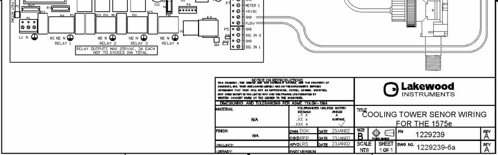
69
PULSAFEEDER MODEL 3210 MICROPROCESSOR-BASED CONDUCTIVITY CONTROLLER INSTALLATION & OPERATION MANUAL SERIAL #:
 PULSAFEEDER MODEL 3210 MICROPROCESSOR-BASED CONDUCTIVITY CONTROLLER INSTALLATION & OPERATION MANUAL SERIAL #: Table of Contents 1 1.0 Introduction... 1-4 1.1 FEATURES... 1-4 1.2 BENEFITS... 1-4 2 Specifications...
WATER TREATMENT SYSTEM CONDUCTIVITY CONTROLLER
 LAKEWOOD INSTRUMENTS MODEL 1575 WATER TREATMENT SYSTEM CONDUCTIVITY CONTROLLER INSTALLATION & OPERATION MANUAL SERIAL #: Lakewood Instruments 7838 North Faulkner Road, Milwaukee, WI 53224 USA Phone (414)
ORP/MILLIVOLT CONTROLLER
 LAKEWOOD INSTRUMENTS MODEL 330 ORP/MILLIVOLT CONTROLLER INSTALLATION & OPERATION MANUAL SERIAL #: Lakewood Instruments 7838 North Faulkner Road, Milwaukee, Wisconsin 53224 USA Phone (800) 228-0839 Fax
ph COOLING TOWER CONTROLLER
 LAKEWOOD INSTRUMENTS MODEL 350 ph COOLING TOWER CONTROLLER INSTRUCTION MANUAL SERIAL #: Lakewood Instruments 7838 North Faulkner Road, Milwaukee, WI 53224 USA Phone (800) 228-0839 Fax (414) 355-3508 http://www.lakewoodinstruments.com
Use this Specification Template to develop a specification to be used for requesting a quote or defining a job work description.
 Use this Specification Template to develop a specification to be used for requesting a quote or defining a job work description. This document is a framework for creating a specification. It may contain
LAKEWOOD INSTRUMENTS MODEL 353 ORP/MILLIVOLT CONTROLLER
 LAKEWOOD INSTRUMENTS MODEL 353 ORP/MILLIVOLT CONTROLLER INSTRUCTION MANUAL SERIAL #: Lakewood Instruments 7838 North Faulkner Road, Milwaukee, WI 53224 USA Phone (800) 228-0839 Fax (414) 355-3508 http://www.lakewoodinstruments.com
Manual. NanoTron Conductivity. Installation Maintenance Repair Manual
 Manual NanoTron Conductivity Installation Maintenance Repair Manual ENTER Advantage Controls P.O. Box 1472 Muskogee, OK 74402 Phone: 800-743-7431 Fax: 888-686-6212 www.advantagecontrols.com email: support@advantagecontrols.com
MICROtrac MICROPROCESSOR BASED WATER TREATMENT CONTROLLER. Installation and Operation Manual REV. L
 MICROtrac MICROPROCESSOR BASED WATER TREATMENT CONTROLLER Installation and Operation Manual MICROtrac Warranty Pulsafeeder, Inc. warrants MICROtrac control systems (including the conductivity sensor) of
MYRIAD TRIPLEX PUMP CONTROLLER INSTRUCTION MANUAL
 MYRIAD TRIPLEX PUMP CONTROLLER INSTRUCTION MANUAL MYRIAD TPC VISIT OUR WEBSITE SIGMACONTROLS.COM MYRIADI&O062705 2 TABLE OF CONTENTS INTRODUCTION 3 Ordering Information Specifications Features WIRING 7,8
Parts Diagram. Up button. Down button. Right (fan) button. Left (system) button. RC/RH Jumper. Field programming pins
 button. Left (system) button. RC/RH Jumper. Field programming pins") Table of Contents Parts Diagram........................................................... 1 Icon Descriptions......................................................... 2 Specifications...........................................................
Table of Contents Parts Diagram........................................................... 1 Icon Descriptions......................................................... 2 Specifications...........................................................
D3000. Installation & Setup Guide
 Page 1 of 15 17483-00 Rev B s1 April 2009 Contents Description Page Safety... 3 Installation Standards 3 Specification. 3-4 Circuit Board Connection 5 Mounting Dimensions 6 Installation Procedure 6 Mechanical
Table of Contents 1. OVERVIEW SYSTEM LAYOUT SPECIFICATIONS FUNCTION... 11
 Table of Contents 1. OVERVIEW... 3 2. SYSTEM LAYOUT... 4 3. SPECIFICATIONS... 8 3.1 SYSTEM COMPONENTS...9 3.2 PLC INPUTS AND OUTPUTS...9 3.3 FUNCTION KEYS...10 3.4 DEFAULT SET POINTS AND TIMERS...10 4.
IMPORTANT SAFETY INSTRUCTIONS READ AND FOLLOW ALL INSTRUCTIONS SAVE THESE INSTRUCTIONS
 Operating Manual MODEL RC554P AND 554200 ph Digital Controller FEED ph FLOW ALERT AUTO MODE SET LEVEL FEED TIME ph CALIB FLOW SWITCH ph ph OUTPUT POWER IMPORTANT SAFETY INSTRUCTIONS READ AND FOLLOW ALL
Rooftop Thermostat Controller Specification and Installation Instructions. Model TRT2422
 ºF / º C Rooftop Thermostat Controller Model TRT2422 Description The TRT2422 is a combination controller and thermostat with a built-in scheduler, which is designed for simple and accurate control of single
Oxygen (O2) Single-Point Gas Detection System
 Single-Point Gas Detection System") Oxygen (O) Single-Point Gas Detection System DESCRIPTION Wall-mounted gas monitor with built-in oxygen (O) sensor, accepts one analog remote device such as a secondary gas sensor, temperature or humidity
Oxygen (O) Single-Point Gas Detection System DESCRIPTION Wall-mounted gas monitor with built-in oxygen (O) sensor, accepts one analog remote device such as a secondary gas sensor, temperature or humidity
Analog Room Pressure Monitor RPC Series
 Description The Room Pressure Monitor is used to measure differential pressure in the range of 0.125 to 1"wc or 30 to 250 Pa. It combines precision high sensitivity silicon sensing capabilities and the
SC Installation, Operation & Application Guide
 SC 5211 2-Stage Heat Pump Auto Changeover Hardwire Programmable Electronic Thermostat 7-Day, 5-2-Day or 5-1-1-Day Programmable Configurable 2-Stage Heat Pump Systems Large Display With Backlight Selectable
DIESEL Engine Fire Pump Controllers Features
 September 007 DIESEL Engine Fire Pump Controllers Features FD0 Diesel Engine Controllers 1-1 Printer / Recorder The industrial grade thermal printer is housed in a rugged steel enclosure within the controller.
Smart Temp. ApolloP/n Installation Manual. Version 1.0
 Smart Temp ApolloP/n 44-800 Installation Manual Version 1.0 TABLE OF CONTENTS Introduction...6 Getting started...7 Installing the thermostat...8 Disassembly...8 Thermostat location...8 Mounting the subbase...8,
Pump-Up Controller MODEL 4062
 Pump-Up Controller 4-20mA Input/Scalable Output Seal Fail Monitoring Duplex Pump Alternation Hand-Off-Auto Controls Dual Run-time Meters RS-485/Modbus Communications DESCRIPTION The Model 4062 Pump-Up
ModSync Sequencing System Installation & Operation Manual. For use with Fulton Steam Boilers.
 ModSync Sequencing System Installation & Operation Manual For use with Fulton Steam Boilers. Revision 3.0 8/21/2008 - 2 - Table of Contents Introduction Page 4 Features Page 4 Sequence of Operation Page
Tempco Part Number PCT30006 Temperature Control Enclosure with Relay Output for Tote Tank Heating Applications
 Instruction Manual Tempco Part Number PCT30006 Temperature Control Enclosure with Relay Output for Tote Tank Heating Applications Manual PCT30006, Revision 9/20/2016 The PCT30006 control enclosure incorporates
Nitrogen Dioxide (NO2) Single-Point Gas Detection System
 Single-Point Gas Detection System") Nitrogen Dioxide (NO) Single-Point Gas Detection System DESCRIPTION Wall-mounted gas monitor with built-in nitrogen dioxide (NO)/diesel fume gas sensor, accepts one analog remote device such as a secondary
Nitrogen Dioxide (NO) Single-Point Gas Detection System DESCRIPTION Wall-mounted gas monitor with built-in nitrogen dioxide (NO)/diesel fume gas sensor, accepts one analog remote device such as a secondary
CommStat 4. Controller for Redundant Telecom HVAC Systems PRODUCT DATA SHEET. Features and Benefits
 CommStat 4 PRODUCT DATA SHEET Controller for Redundant Telecom HVAC Systems General Description The CommStat 4 is an HVAC controller designed specifically for controlling two redundant air conditioners,
Pump-Down Controller MODEL 4052
 Pump-Down Controller 4-20mA Input/Scalable Output Seal Fail Monitoring Duplex Pump Alternation Hand-Off-Auto Controls Dual Run-time Meters RS-485/Modbus Communications DESCRIPTION The Model 4052 Pump-Down
IMPORTANT SAFETY INSTRUCTIONS READ AND FOLLOW ALL INSTRUCTIONS SAVE THESE INSTRUCTIONS
 Operating Manual MODEL RC554X AND 554230 ORP Digital Controller FEED ALERT ORP FLOW AUTO MODE SET LEVEL FEED TIME FLOW SWITCH ORP ORP OUTPUT POWER IMPORTANT SAFETY INSTRUCTIONS READ AND FOLLOW ALL INSTRUCTIONS
Refrigeration Controller Operator s Manual (HRC) PO Box 6183 Kennewick, WA
 PO Box 6183 Kennewick, WA") Refrigeration Controller Operator s Manual (HRC) PO Box 6183 Kennewick, WA 99336 www.jmcvr.com 1-509-586-9893 Table of Contents TABLE OF FIGURES...1 OVERVIEW OF THE HRC CAPABILITIES...2 INSTALLATION AND
Refrigeration Controller Operator s Manual (HRC) PO Box 6183 Kennewick, WA 99336 www.jmcvr.com 1-509-586-9893 Table of Contents TABLE OF FIGURES...1 OVERVIEW OF THE HRC CAPABILITIES...2 INSTALLATION AND
SCM. Micro. Streaming Current Monitor. Analyzer. Sensor/Sampler with light shield removed. The Analyzer. Instrument Overview
 Micro SCM Streaming Current Monitor A Watts Water Technologies Company Instrument Overview The instrument consists of the Analyzer and the SCM sensor. Analyzer The Analyzer The monitor has a built in graphic
ROYCE SUSPENDED SOLIDS SYSTEM MODEL 7011A AND SENSORS MODELS 72A, 72P, 73B, 74A, 75A & 76A
 SPECIFICATIONS (Revised 1/12/2006) ROYCE SUSPENDED SOLIDS SYSTEM MODEL 7011A AND SENSORS MODELS 72A, 72P, 73B, 74A, 75A & 76A The system shall operate on the principle of light absorption. It shall consist
EXPERT TRI-STAR. Temperature controller. User s Manual
 Temperature controller r s Manual WARNINGS The warranty can be void if this product is used in a manner not specified by the manufacturer. Every effort has been made to ensure that this manual is complete,
Controller Specification Sheet
 Controller Specification Sheet MC9550ABXXBX Proportional Inhibitor Dosing, Dual Conductivity Bleed Control, Dual Point ph Control, Redox Control of Oxidising Biocide and Secondary Biocide Dosing PULSAtrol
RATIO:GUARD Model E-1S EC Monitor
 EC probe Probe tees Probe retention clips Temperature probe E-1S monitor box UNPACKING Please open and inspect your package upon receipt. Your package was packed with great care and all the necessary packing
Tempco PCT-3000 Series Temperature Control Console with Relay Output for Heating or Cooling Applications
 Instruction Manual Tempco PCT-3000 Series Temperature Control Console with Relay Output for Heating or Cooling Applications Manual PCT-3000 Revision 9/2014 The PCT-3000 series control console incorporates
OWNER S MANUAL. Vintage Classic HEAT COOL models. Proudly Made in the USA
 OWNER S MANUAL Vintage Classic HEAT COOL models Proudly Made in the USA support@aquacomfort.com www.aquacomfort.com/service-and-support 888-475-7443 Manufacturing High Quality, High Efficiency Heat Pump
ERV-24. Technician Settings & Operating Manual. Protected by one or more of the following patents: US 5,547,017; 5,881,806; 6,431,268; CA 2,245,135
 ERV-24 Technician Settings & Operating Manual Protected by one or more of the following patents: US 5,547,017; 5,881,806; 6,431,268; CA 2,245,135 1 Introduction brief description General The ERV-24-HC11
HP727S. Single speed swimming pool heat pump controller Operation manual TABLE OF CONTENTS
 HP727S Single speed swimming pool heat pump controller Operation manual TABLE OF CONTENTS 1. General Description 2. Specifications 3. Installation Instructions 4. Electrical Wiring 5. Instrument Wiring
F PC and AO OUTPUT BOARDS INSTRUCTION MANUAL. Blue-White. Industries, Ltd.
 F-2000 PC and AO OUTPUT BOARDS INSTRUCTION MANUAL Blue-White R Industries, Ltd. 500 Business Drive Huntington Beach, CA 92649 USA Phone: 714-89-8529 FAX: 714-894-9492 E mail: sales@blue-white.com or techsupport@blue-white.com
Steamist Installation Guidelines
 Steamist Installation Guidelines The Heavy Commercial steam generator (HC-9 thru HC-18) comes from the factory assembled, carefully wired, and tested. Please read all instructions before installing or
1.2.3 Returning Instrument for Repair.
 2 Contents Installation....Page 5 Electrical and I/O...Page 8 Operating Principle...Page 11 Specifications.......Page 12 Operation.Page 14 Menu Screens......Page 15 Installation Tips and Troubleshooting.
SC Installation, Operation & Application Guide
 SC 3006 Auto Changeover 7-Day Programmable Hardwired Programmable Electronic Thermostat 7-Day Programmable Single Stage Heat Pump/Non-Heat Pump Systems Backlit Display Single Stage Heat/Cool Systems Field
CommStat 6. Controller for Redundant HVAC Systems PRODUCT DATA SHEET
 CommStat 6 Controller for Redundant HVAC Systems PRODUCT DATA SHEET General Description The CommStat 6 HVAC controller is designed for controlling up to six redundant air conditioners in an E-House or
Excellence through Versatility
 Controllers Excellence through Versatility Located in Acton, Massachusetts, Liquid Metronics has been providing quality products and service to the water treatment industry worldwide for over 20 years.
Comfort System T-21-P Touchscreen Thermostat Installation Manual
 Comfort System T-21-P Touchscreen Thermostat Installation Manual Version 1.40 INTRODUCTION The Comfort System T-21-P is a feature-rich touchscreen thermostat that can be battery powered or hardwired to
T-32-TS Touchscreen Thermostat. Installation Manual
 T-32-TS Touchscreen Thermostat Installation Manual TABLE OF CONTENTS Introduction...4 Getting Started...5 Installing the Thermostat...6, 8 Disassembly...6 Thermostat Location...6 Mounting the Subbase...6,
Condensate Monitoring OM0232
 3D TRASAR Boiler Technology 33 Condensate Monitoring Basics Date 4-18-11 Version 1.0 Nalco Global Equipment Solutions 1601 West Diehl Road Naperville, IL 60563-1198 Nalco Global Equipment Solutions 2 Table
M770 ph Controller Owner s Manual
 M770 ph Controller Owner s Manual Table of Contents I. Introduction page 2 A. Water Chemistry page 2 B. Safety page 3 C. System Components page 4 D. Specifications page 7 E. Controller Panel Descriptions
Owner s Manual RD432-0 Chemical Controller
 Owner s Manual RD432-0 Chemical Controller Table of Contents I. Introduction page 2 A. Water Chemistry page 2 B. Safety page 3 C. System Components page 4 D. Specifications page 7 E. Controller Panel Descriptions
Operator's Manual Dielman Rock Island Industrial Dr. St. Louis, MO Tel:(314)
") Operator's Manual TABLE OF CONTENTS Firmware Version... 1 Environmental Conditions... 1 Electrical Specifications... 1 Warnings... 2 Section A: Programming the Controller... 3 A 1: Adjusting the Display
Operator's Manual TABLE OF CONTENTS Firmware Version... 1 Environmental Conditions... 1 Electrical Specifications... 1 Warnings... 2 Section A: Programming the Controller... 3 A 1: Adjusting the Display
VAV Thermostat Controller Specification and Installation Instructions. Model TRO24T4XYZ1
 Model TRO24T4XYZ1 Description The TRO24T4XYZ1 is a combination controller and thermostat. The VAV Thermostat Controller is designed for simple and accurate control of any variable air volume box in a number
MicroVision MICROPROCESSOR BASED WATER TREATMENT CONTROLLER. Installation Operation Manual Rev. N Page 1 of 43
 MicroVision MICROPROCESSOR BASED WATER TREATMENT CONTROLLER Installation Operation Manual Page 1 of 43 Table of Contents 1. INTRODUCTION... 4 2. MICROVISION FEATURES... 4 2.1 Toroidal Probe... 4 2.2 Output
TABLE OF CONTENTS. Principle of operation of CAFM...1. Installation instructions...2. Main ADC Operating screen...3. Set process temp and Setback...
 TABLE OF CONTENTS Principle of operation of CAFM....1 Installation instructions......2 Main ADC Operating screen......3 Menu definitions of ADC control Set process temp and Setback.....4 7-Day timer and
Installation, Start-Up, and Operating Instructions
 Installation, Start-Up, and Operating Instructions CONTENTS Page SAFETY CONSIDERATIONS...1 GENERAL...1 INSTALLATION...1-5 Install Batteries...1 Select Transmitter Location (Optional)...1 Mount Transmitter
SAMPLE MANUAL - INSTALLATION - FOR REFERENCE ONLY. ChemScan mini Analyzer. Parameter. Method #### Installation, Operation & Maintenance Manual
 Parameter Method ####, Operation & Maintenance Manual Rev 3/26/2018 Contact Information Document Information Customer Name: Plant Name/Location: Date: Analyzer Serial #: ASA, Inc. (Applied Spectrometry
IMPORTANT SAFETY INSTRUCTIONS READ AND FOLLOW ALL INSTRUCTIONS SAVE THESE INSTRUCTIONS
 Operating Manual MODELS RC554XP AND 554000 ORP/pH Digital Controller FEED ph ALERT FEED ORP ALERT F LOW ph MODE AUTO FEED ONCE SET LEVEL FEED TIME HI LOW ph CALIB ORP ph ORP IMPORTANT SAFETY INSTRUCTIONS
Product Manual SZ1009
 Product Manual SZ1009 Conventional Heating & Cooling Thermostats with Heat Pump Mode Communicating Thermostats Description The SZ1009 is a microprocessor-based mable thermostats designed for conventional
ORP (mv) Controller Model: ORP-XP2. UP DOWN ENTER Time & Date Main Menu Alarm Reset
 Controller Model: ORP-XP2. UP DOWN ENTER Time & Date Main Menu Alarm Reset") Instruction Manual ORP (mv) Controller Model: ORP-XP2 Power Control Alarm Comms UP DOWN ENTER Time & Date Main Menu Alarm Reset Supplied by: Convergent Water Controls Pty Ltd 2/4 Huntley Street, PO Box
Instruction Manual ORP (mv) Controller Model: ORP-XP2 Power Control Alarm Comms UP DOWN ENTER Time & Date Main Menu Alarm Reset Supplied by: Convergent Water Controls Pty Ltd 2/4 Huntley Street, PO Box
SC Installation, Operation & Application Guide
 SC 5811 2 Heat/2 Cool Auto Changeover Hardwire Programmable Electronic Thermostat 7-Day, 5-2-Day or 5-1-1-Day Programmable Configurable 2-Stage Heat/2-Stage Cool Systems 2-Stage Heat Pump Systems Large
MASTER JOCKEY PUMP CONTROLLER. Model JPCE INSTRUCTION MANUAL. C 2018 Master Control Systems, Inc
 MASTER JOCKEY PUMP CONTROLLER Model JPCE INSTRUCTION MANUAL C 2018 Master Control Systems, Inc TABLE OF CONTENTS Important Safety Information. Page 3 General Description and Installation.. Page 4 Model
Smart Temp. Model
 Smart Temp Model 42-160 SINGLE STAGE PROGRAMMABLE THERMOSTAT 1 Heat / 1 Cool Single Stage Thermostat. 5+2 Programmable, Compatible with Gas Heat & Heat Pump System Installation and Operation Manual SPECIFICATIONS:--------------------------------------------------------------------------------
Beacon 800 Gas Monitor Operator s Manual
 Beacon 800 Gas Monitor Operator s Manual Part Number: 71-0037RK Revision: F Released: 4/18/17 www.rkiinstruments.com Product Warranty RKI Instruments, Inc. warrants gas alarm equipment sold by us to be
Digital Programmable
 www.geappliances.com Digital Programmable Thermostats Operating Instructions Auto Changeover..........10 Day/Time Setting Mode.....6 Default Mode...............4 Fan Control...............10 Hold and Temporary
microflex Blowdown Controller for Boilers Measures Conductivity, Temperature, Make-up Water Meter and Interlock
 microflex Blowdown Controller for Boilers Measures Conductivity, Temperature, Make-up Water Meter and Interlock Controls the Blowdown Valve and the Inhibitor Pump Part No. BB-IN CONTENTS Safety 1. INSTALLATION
Browser Manual ProMinent ProMtrac Cooling Tower Water Treatment Controller
 Browser Manual ProMinent ProMtrac Cooling Tower Water Treatment Controller ProMtrac_Browser_Manual.docx (5/23/13) rev1: pn. 7501088 Please completely read through these operating instructions first! Do
User s Manual. TIGER S EYE E-Series Mark V Jockey. TIGERFLOW Systems, Inc Mint Way Dallas, Texas
 User s Manual TIGER S EYE E-Series Mark V Jockey TIGERFLOW Systems, Inc. 4034 Mint Way Dallas, Texas 75237 214-337-8780 www.tigerflow.com TABLE OF CONTENTS Introduction... 4 Sequence of Operation... 5
RCS Residential Control Systems Inc.
 RCS Residential Control Systems Inc. Model TZ16 Z-Wave Communicating Thermostat with Rev P HVAC Control Unit INSTALLATION AND OPERATION MANUAL DCN: 141-00882 Rev 02 5/18/06 This manual applies to the following
SlimFlex microflex: HELP
 HELP Links The first line of the controller LCD display may display a help number?123 where 123 is a HELP number from 010 to 255. Example: LCD Displays Off@ 995?121 ON 1299uS?121 The Bleed Solenoid is
1025, BOUL. MARCEL-LAURIN INSTRUCTION MANUAL FOR WATER COOLED ENVIROCHILL CHILLER. Prepared par Claude Gadoury, P. Eng MTL TECHNOLOGIES INC.
 WYETH-AYERST CANADA INC. 1025, BOUL. MARCEL-LAURIN S T - L A U R E N T, Q U É B E C INSTRUCTION MANUAL FOR WATER COOLED ENVIROCHILL CHILLER MODEL P448800LT--55WC--22C66S Prepared par Claude Gadoury, P.
AS950 REFRIGERATED SAMPLERS
 AS950 REFRIGERATED SAMPLERS Applications Wastewater Collections Industrial Pretreatment Environmental Monitoring Stormwater Sampling has never been this easy. The AS950 Refrigerated Sampler makes programming,
AUTOTROL 363TC AUTOMATIC FILTER VALVE SERVICE MANUAL
 AUTOTROL 363TC AUTOMATIC FILTER VALVE SERVICE MANUAL 2013 Pentair Residential Filtration, LLC www.pentairaqua.com/pro TABLE OF CONTENTS MANUAL OVERVIEW... 2 SAFETY INFORMATION... 2 TYPICAL TOOLS AND FITTINGS
Digi-Sense TC9000 Advanced PID and On/Off Temperature Controller with Thermocouple Input
 User Manual 99 Washington Street Melrose, MA 02176 Phone 781-665-1400 Toll Free 1-800-517-8431 Visit us at www.testequipmentdepot.com Digi-Sense TC9000 Advanced PID and On/Off Temperature Controller with
HALOGUARD TM IR MONITOR (OPTIONAL) FOUR or EIGHT POINT SCANNER INSTRUCTION MANUAL
 FOUR or EIGHT POINT SCANNER INSTRUCTION MANUAL") HALOGUARD TM IR MONITOR (OPTIONAL) FOUR or EIGHT POINT SCANNER INSTRUCTION MANUAL SE R IA L N O. M O D E L N O. Tem p. Range 1 - = > 60 o F 2 - = 40-60 o F 3 - = < 40 o F G as Type 1 - R-11 2 - R-12 3
HALOGUARD TM IR MONITOR (OPTIONAL) FOUR or EIGHT POINT SCANNER INSTRUCTION MANUAL SE R IA L N O. M O D E L N O. Tem p. Range 1 - = > 60 o F 2 - = 40-60 o F 3 - = < 40 o F G as Type 1 - R-11 2 - R-12 3
Beacon 200 Gas Monitor Operator s Manual. Part Number: RK Released: 6/6/08
 Beacon 200 Gas Monitor Operator s Manual Part Number: 71-2102RK Released: 6/6/08 Table of Contents Chapter 1: Introduction.................................................3 Overview.............................................................3
TMC. Installation and Operation Manual TMC. Temperature and Pressure Monitoring for Heating and Cooling Applications. Temperature Monitoring Control
 Installation and Operation Manual Temperature and Pressure Monitoring for Heating and Cooling Applications Temperature Monitoring Control VALVE OPEN ALARM System= 128 o F Alarm At= 130 o F RESET /BACK
Two-Channel Gas Controller
 Two-Channel Gas Controller Specifications subject to change without notice. USA 09 Page of DESCRIPTION Highly configurable, UL 0 performance-tested and -certified, and wall-mounted gas monitor; continuously
M790 ph/orp Controller. Owner s Manual
 M790 ph/orp Controller Owner s Manual Table of Contents I. Introduction page 2 A. Water Chemistry page 2 B. Safety page 3 C. System Components page 4 D. Specifications page 7 E. Controller Panel Descriptions
MYRIAD DPC DUPLEX PUMP CONTROLLER INSTRUCTION MANUAL VERSION 3.7
 MYRIAD DPC DUPLEX PUMP CONTROLLER INSTRUCTION MANUAL VERSION 3.7 VISIT OUR WEBSITE SIGMACONTROLS.COM MYRIAD DPC MANUAL 013114 1 2 TABLE OF CONTENTS INTRODUCTION 3 Ordering Information Specifications Features
DEMA TITAN EP II WAREWASH CONTROL TE.812 & TE.813 SERIES
 DEMA TITAN EP II WAREWASH CONTROL TE.812 & TE.813 SERIES Overview The Titan EP ware wash system controls all chemical delivery functions for dish machines and similar warewash applications. The system
OPERATING AND MAINTENANCE MANUAL FOR PLATE HEAT EXCHANGER INDIRECT FIRED WATER HEATER. Electric Heater Company Base Model "BWXP"
 OPERATING AND MAINTENANCE MANUAL FOR PLATE HEAT EXCHANGER INDIRECT FIRED WATER HEATER Electric Heater Company Base Model "BWXP" HUBBELL ELECTRIC HEATER COMPANY P.O. BOX 288 STRATFORD, CT 06615 PHONE: (203)
Phone-A-Stat. MODEL Command Center With Thermostat Operation, Maintenance & Installation Manual. Introduction.
 Introduction The UL listed Phone-A-Stat (model # 7632 ) is designed and approved for the safe operation of remotely controlling four independent loads, such as a sprinkler system or a water heater via
Integrated Automation Instrumentation & Terminal Devices
 Sections Included In This Standard: 1.1 Building Systems Control 1.2 Building Aumotation Systems (BAS) 1.1 BUILDING SYSTEMS CONTROL A. HVAC CONTROLS: 1. General: Temperature control zones shall not combine
PF1000 CONTROLLER. for the. Heateflex Corporation 405 E. Santa Clara St. Arcadia, CA TEL: (626) ; FAX: (626)
 ; FAX: (626)") PF1000 CONTROLLER for the AQUARIUS I/II DEIONIZED WATER HEATING SYSTEM Heateflex Corporation 405 E. Santa Clara St. TEL: (626)599-8566; FAX: (626)599-9567 Rev. 07 10/19/10, (PF1000) 1 2 TABLE OF CONTENTS
PF1000 CONTROLLER for the AQUARIUS I/II DEIONIZED WATER HEATING SYSTEM Heateflex Corporation 405 E. Santa Clara St. TEL: (626)599-8566; FAX: (626)599-9567 Rev. 07 10/19/10, (PF1000) 1 2 TABLE OF CONTENTS
Installation, Operation & Maintenance Manual. Wash System
 Installation, Operation & Maintenance Manual Wash System Kleen Flo Wash System Installation, Operation & Maintenance Manual CONTENTS Introduction and Overview... 3 Pipeline Wash System Features... 5 Wash
CommStat 4 Controller
 CommStat 4 Controller CommStat 4 Telecom HVAC Controller The CommStat 4 is an HVAC controller designed specifically for controlling two redundant air conditioners, heat pumps and air conditioners with
TYPE CM-2201 NELSON SINGLE POINT CIRCUIT MANAGEMENT SYSTEM
 2 Line, 16 Characters/row LCD Display Temperature Input Range -50 C to +500 C -58 F to + 932 F Enclosure NEMA Type 4X Current Rating 30A max (resistive load only) Ambient Temperature -40 C to + 40 C -40
ECC-1 user manual and installation guide
 ECC-1 user manual and installation guide Table of contents Introducing the ECC-1...1 Features...2 Electrical ratings...2 Optional accessories...3 About this manual...3 Using the buttons...4 About the status
Tri-Stack Smart System
 Tri-Stack Smart System TM Notes & Warnings - The protection provided by this equipment may be impaired if it is not used in the manner specified herein. - Ensure all wiring meets applicable national and
Dryer Controller M720
 User Manual Dryer Controller M720 Hardware version 2.00 Software version 2.00 Manual M720 Dryer controller Page 1 of 60 Document history Preliminary version: - Created in April, 2009 Hardware Version 2.00,
INSTRUCTIONS FOR E-SERIES WATER PURIFICATION MACHINES 57,000 GPD TO 288,000 GPD 216 M3/D to 1090 M3/D OPERATION AND MAINTENANCE MANUAL
 INSTRUCTIONS FOR E-SERIES WATER PURIFICATION MACHINES 57,000 GPD TO 288,000 GPD 216 M3/D to 1090 M3/D OPERATION AND MAINTENANCE MANUAL TABLE OF CONTENTS 1.0 DESCRIPTION................................................................
DIGITAL METERS Large Display Temperature Meters Instruction Manual
 DIGITAL METERS Large Display Temperature Meters PD755 PD756 PD757 Handles Thermocouple & RTD Inputs with Simplicity J, K, T, E, R, & S Thermocouples 100 Ω Platinum RTD (0.00385 or 0.00392 curve) Large
MASTER PRESSRE MAINTANENCE CONTROLLER. Models PMCE INSTRUCTION MANUAL. C 2018 Master Control Systems, Inc
 MASTER PRESSRE MAINTANENCE CONTROLLER Models PMCE INSTRUCTION MANUAL C 2018 Master Control Systems, Inc TABLE OF CONTENTS Important Safety Information. Page 3 General Description and Installation.. Page
Emerson Blue Easy Set 1H/1C
 Emerson Blue Easy Set 1H/1C Model: 1F86EZ-0251 Non-Programmable Thermostat with 3 Temperature Pre-Sets Home, Sleep and Away Installation Instructions and User Guide Message to Homeowner Congratulations
Software Version 2.01 LEVEL MONITOR MODEL 220
 Software Version 2.01 LEVEL MONITOR MODEL 220 19 April 2000 CONTENTS 1. Introduction 1 1.1 Model Number Designation 2 1.2 Intrinsic Safety Considerations 3 2. Specification 4 3. Operation 6 3.1 Display
9901i 9915i 9920i. User's Manual. Menu Driven Display. Fresh Air Control DELUXE PROGRAMMABLE THERMOSTATS
 9901i 9915i 9920i DELUXE MABLE THERMOSTATS User's Manual Menu Driven Display Integrated Damper / Economizer Control 24 VAC with Worry-Free Memory Storage English and Spanish Menus Fresh Air Control 110-1069
CP CP
 CP-8161-333 CP-8161-433 Electronic Programmable Controller Six Stage, Dual Setpoint General Instructions APPLICATION Electronic six stage programmable controller with proportional output for heating, cooling
GG-2 2-CHANNEL GAS DETECTION CONTROL PANEL. Installation and Operation Manual
 GG-2 2-CHANNEL GAS DETECTION CONTROL PANEL Installation and Operation Manual 2 GG-2 Warning Use this product only in the manner described in this manual. If the equipment is used in a manner not specified
INSTALLATION MANUAL. * If using remote sensors the thermostat must be hardwired. Need Help?
 INSTALLATION MANUAL This manual covers the following models: T955W Master Thermostat Base Module Thermostat Applications Guide Description Gas or Oil Heat Electric Furnace Heat Pump (No Aux. or Emergency
USER MANUAL MODEL READ ALL INSTRUCTIONS BEFORE PROCEEDING. 5-2 Day Programmable Multi-Stage 2 Heat/1 Cool Heat Pump Digital Thermostat
 WARNING! Important Safety Information Builder MODEL 2200 Series 5-2 Day Programmable Multi-Stage 2 Heat/1 Cool Heat Pump Digital Thermostat USER MANUAL Compatible with low voltage multi stage heat/cool
INSTALLATION MANUAL. Need Help? This manual covers the following models: T915. Power Type. Thermostat Applications Guide. Page.
 INSTALLATION MANUAL This manual covers the following models: T915 Thermostat Applications Guide Des cription Gas or Oil Heat Electric Furnace Heat Pump (No Aux. or Emergency Heat) Heat Pump (with Aux.
GASGUARDIAN Channel Controller OPERATING & INSTALLATION MANUAL
 GASGUARDIAN 2 3 2-Channel Controller OPERATING & INSTALLATION MANUAL GasGuardian 2 3 Operating and Installation Manual Table of Contents General description.... 3 Installation. 3 Locating the GasGuardian-2..
D3000. Installation and Operating Manual SAFETY D3000 SPECIFICATIONS PRODUCT DESCRIPTION
 D3000 Installation and Operating Manual SAFETY Always wear the required Personal Protective Equipment (such as safety glasses, gloves, face shields, and aprons) when potentially exposed to any hazardous