FINAL THESIS REPORT. Oklahoma University Children s Medical Office Building OKLAHOMA UNIVERSITY CHILDREN S MEDICAL OFFICE BUILDING
|
|
|
- Katrina Hamilton
- 6 years ago
- Views:
Transcription

1 FINAL THESIS REPORT Oklahoma University Children s Medical Office Building Oklahoma City, Oklahoma A l e c T. C a n t e r M e c h a n i c a l O p t i o n B a c h e l o r o f A r c h i t e c t u r a l E n g i n e e r i n g F a c u l t y A d v i s o r : L a u r a M i l l e r 4 / 9 / 2 1 4

2 1
3 Contents Acknowledgements... 6 Executive Summary... 7 Part I: Existing Design Analysis... 8 Existing Project Conditions... 8 Building Overview... 8 Systems Overview... 8 Project Team... 9 ASHRAE Standard 9.1 Energy Standard for Buildings... 9 Chapter 5 Building Envelope... 9 Chapter 6 Heating, Ventilation, and Air Conditioning... 1 Chapter 7 Service Water Heating Chapter 8 Power Chapter 9 Lighting Mechanical System Outdoor & Indoor Design Conditions Ventilation Heating & Cooling Existing Mechanical Equipment Air Handling Units Air Terminal Units Hydronic Unit Heaters Packaged Terminal Heat Pumps Fan Coil Units System Operation Airside Waterside Mechanical System Space ASHRAE Standard 62.1 Ventilation for Acceptable Indoor Air Quality Chapter 5. Systems & Equipment Chapter 6. Ventilation Rate Calculations Procedure... 2 Part II: Proposed Redesign
4 Proposed Alternative Mechanical Depth Acoustics Breadth Electrical Breadth Redesign Introduction Redesign System Operation VRF Design & Model VRF Evaluation and Comparison Acoustics Breadth Electrical Breadth References APPENDIX A: Ventilation Schedules... APPENDIX B: Acoustics Breadth, Sound Power Level Attenuation Calculations... APPENDIX C: Rooftop/Outdoor Condenser Connections Schedule APPENDIX D: Required Equipment Efficiencies for Compliance
5 Figures & Tables Figure 1. Climate Zones for United States Locations..7 Figure 2. Building Envelope Requirements for Climate Zone 3 (A, B, C).8 Figure 3. Bird Screens and Goosenecks...15 Figure 4. Plan View of Air Handling Unit with Access Doors Figure 5. Exterior Wall Section indicating Weather-Proofing.. 18 Figure 6: Typical Layout of a VRF System (taken from ASHRAE).24 Figure 7. VRF Heat Recovery Diagram...26 Figure 8. Basement Floor (Floor ) Zoning..27 Figure 9. Third Floor Zoning 27 Figure 1. Fourth Floor Zoning. 28 Figure 11. Fifth Floor Zoning...28 Figure 12. Sixth Floor Zoning...28 Figure 13. Seventh Floor Zoning Figure 14. Eighth Floor Zoning.28 Figure 15. Ninth Floor Zoning..28 Figure 16. Tenth Floor Zoning..28 Figure 17. Annual Electricity Comparison 3 Figure 18. Original Cost Breakdown Figure 19. Proposed Design Cost Breakdown...31 Figure 2. Noise Criteria Curve 34 Table 1. Building Design Conditions....1 Table 2. Ventilation Rate Results Summarized 1 Table 3. Heating & Cooling Design vs. Trace Flow Rates..11 Table 4. AHU Schedule.12 4
6 Table 5. Thermostat Setting.19 Table 6. Common Room Occupancy..2 Table 7. Space Lighting and Equipment Loads.21 Table 8. Typical Construction Assemblies..22 Table 9. Airflow Comparison.22 Table 1. VRF Cooling and Heating Required 27 Table 11. Condenser Schedule.29 Table 12. Air Handling Units vs. Dedicated Outdoor Air Units..31 Table 13. Airflow Comparison..31 Table 14. Existing AHU-F Sound Power Levels 32 Table 15. Proposed DOAS Unit and Exhaust Fan Power Levels.32 Table 16. Terminal Unit sound Power Levels.33 Table 17. Room Sound Power and Sound Pressure Levels..33 Table 18. Connection Schedule for the Air Handling Units..35 Table 19. Connection Schedule for the DOAS Units.36 5
7 Acknowledgements The Pennsylvania State University Architectural Engineering Department Thesis Advisor: Dr. Laura Miller Jorge Charneco, AIA; Miles Associates Rob Gould, PE; AKF Group Thanks to all my family and friends 6
8 Executive Summary This senior year thesis project is an investigation into Oklahoma University Children s Medical Office Building and a potential new design that would be practical while accomplishing energy savings, reduced emissions, and better controllability for occupant comfort. The Oklahoma University MOB is part of the hospital campus in downtown Oklahoma City, Oklahoma. It is a 12 story mid-rise building that is reserved primarily for offices. The following report contains two parts, the first of which is the study of the existing conditions such as building envelope, designed systems (emphasizing on the mechanical systems), code compliances, and climate and locale amongst others. The second part of this document contains a proposed redesign of the building which is comprised of three sections. The main mechanical depth is the main section of the redesign proposal. In this section a variable refrigerant volume mechanical system was designed in place of the existing variable air volume system. The variable refrigerant volume system was designed to be paired with floor-by-floor dedicated outdoor air system units to provide the building with 1% outdoor air. The VRF and DOAS couple successfully achieved combined annual electricity and gas savings of 11% as well as reduced the amount of emissions produced. The VRF system also added increased occupant controllability based on the heat recovery option, which allows for simultaneous heating and cooling. Overall, the proposed VRF system outperformed the existing VAV system, except for its high first cost. A life cycle cost analysis discovered the simple payback period of the VRF and DOAS system combination to be approximately fifteen years, even with the annual energy savings, which could discount the system as a viable option. The next two analyses compared the electrical and acoustical characteristics of the system to that of the variable air volume system. For the acoustical breadth, the sound power levels created by the indoor evaporator units and DOAS system were compared against the VAVs and AHUs in the closest rooms downstream from the main mechanical room. Both systems met the acoustical requirements of rooms and rated similarly in noise criteria values. Finally, the electrical connections were calculated for both of the systems air handling devices. They were then compared against each of to see if the DOAS units required larger connections than the existing AHUs. It was discovered that the DOAS unit connections were smaller than that of the existing air handling units, which was found to be a good indicator that the existing panel board and power distribution could accommodate the DOAS units. Additional connections were calculated for the outdoor VRF units to get a better understanding of the electrical load they will require. 7
9 Part I: Existing Design Analysis Existing Project Conditions Building Overview The Oklahoma University Children s MOB is a 337, square foot newly constructed building on the OU hospital grounds. The cost of the project is approximately $6 million, and was set for completion in the spring of 29. The architecture of the building incorporates a brick veneer façade separated visually by large spans of aluminum panels and glass curtain walls achieving a modern appearance. The interior floors are repetitive and feature exterior and interior offices, which are divided by a continuous corridor. Offices and spaces are designated by their corresponding medical use. The building reaches a total of twelve above ground stories, with a basement floor and ground level parking deck. Although the building is designated as a medical building, approximately half of the space is office space. There are currently 3 ½ floors that are unoccupied. Systems Overview The general mechanical layout for the building makes use of an air-handling unit on each of the 11 above-grade floors and 1 basement floor. Each air-handling unit is capable of providing approximately 28 tons of cooling. From the air-handling unit, air is distributed to approximately 4 terminal boxes per floor. All terminal boxes present within the building are intended for variable air volume (VAV). The medical office building uses the plenum space above the rooms for air return and circulation by way of the terminal units and transfer ducts. Additionally, each floor is served by the two mechanical rooms; that which houses the floor s air-handling unit and another at the opposite side of the building were approximately 5% of the distributed air is discharged from the building. All exhaust air travels up to the roof to be relieved. Chilled and heating water is distributed through the building after transfer in the main mechanical room, which is served by a central steam heating plant and a chiller plant both located offsite, but on the hospital campus. Currently, nine of the twelve floors are set to be occupied, leaving three floors with AHUs not yet in operation. Furthermore, egress spaces on the unoccupied floors, parking deck, and stairwells are served by fan coil units. The main power is supplied at 48/277 V from the utility transformer. The electrical distribution is divided into two stacks: the north stack supplies all panel boards serving lighting, receptacles, and other equipment and, additionally directly supplies the air handling units; the south stack serves the critical, life safety, and emergency equipment branches. The main 48/277 V distribution panel serves each stack. A 5kW natural gas generator in the event of power failure also serves the south stack. The structural system uses concrete for the entire height of the building. Each floor features reinforced concrete columns and a grid of reinforced concrete beams. The beams act as column slabs distributing the loads in two directions. Steel framing supports the façade. 8

10 Project Team Owner: Oklahoma University Hospital Trust Construction Manager: Flintco, Inc. Design Architect: Hellmuth, Obata, Kassabaum [HOK] Project Architect: Miles Associates Structural Engineer: Zahl-Ford, Inc. MEP Engineer: ZRDH, P.C. Civil Engineer: Smith-Roberts Baldischwiler, Inc. ASHRAE Standard 9.1 Energy Standard for Buildings Chapter 5 Building Envelope Climate Zones The climate zones for the continental United States increase from zone one to zone seven (eight is only present in Alaska) as temperature decreases and elevation increases from south to north generally. Additionally each county is defined by its relative humidity progressing from A on the east coast and much of the eastern half of the country where climates are considered moist or humid to C on the very edge of the west coast where areas are distinguished as cool and marine. Figure 1. Climate Zones for United States Locations Oklahoma borders zone four to the north and the dry region (B) to the west. All counties in Oklahoma fall in climate zone 3A except Beaver, Cimarron, and Texas counties, which lie in zone 4A. Therefore, Oklahoma University Children s Medical Office Building in Oklahoma City (Oklahoma County) resides in zone 3A, which is described as being warm-humid. 9

11 Section 5.2 Compliance Paths Compliance: The compliance path of the construction follows Section 5.5, the Prescriptive Building Envelope Option. Refer to Section 5.5 for the full requirements. To comply, the vertical fenestration area of the floors must not exceed 4% of the gross wall area and the skylight fenestration area cannot exceed 5% of the gross roof area. The OU Children s Medical Office Building meets both of these categories in that the ratio of vertical wall fenestration to gross wall area is lower than 4%, and there is no skylight fenestration to factor in. Therefore, the Prescriptive Building Envelope Option can be used. Section 5.4 Mandatory Provisions Air Leakage: The entire building envelope is designed to maintain a continuous air barrier. Section 5.5 Prescriptive Building Envelope Option Building Envelope Requirements: OU Children s Medical Office Building is a nonresidential conditioned space; therefore it must comply with the requirements outlined in the table beside for the appropriate climate zone, 3A. Figure 2. Building Envelope Requirements for Climate Zone 3 (A, B, C) [Skylight Fenestration Excluded from Table] Chapter 6 Heating, Ventilation, and Air Conditioning Section 6.2 Compliance Paths Compliance: Compliance will be achieved by meeting all the requirements for Section 6.4, Mandatory Provisions, and Section 6.5, Prescriptive Path. A discussion follows. 1
12 Section 6.4 Mandatory Provisions Equipment Efficiencies, Verification, and Labeling Requirements: All equipment in the building that is shown on the tables in Appendix D must have a minimum performance that it will meet at the specified rating condition. Only the tables containing pertinent equipment have been included. Section 6.5 Prescriptive Path Economizers: Each cooling system that has a fan within the building must include an economizer since all systems are over 54, Btuh. All air handling units in the building utilize an air economizer. Computer cooling does not require an economizer as the building resides in climate zone 3A. Chapter 7 Service Water Heating The steam and heating water used for the building comes from an offsite location, a steam/heating water plant that is elsewhere on the Oklahoma University Hospital campus. This is also true about the chilled water. Once on site the water is then distributed to various heat exchangers and pumps to heat domestic and heating water for the Medical Office Building. Chapter 8 Power The Children s Medical Office Building uses low-voltage dry-type transformers rated at 6 V and less, with capacities up to 1 kva. Under the mandatory provisions section, the feeder conductors cannot impose a voltage drop greater than 2% at design load. Additionally, the branch circuit conductors must not exceed a voltage drop of 3% at design load. Chapter 9 Lighting Only areas such as restrooms, corridors, stairwells, and lobbies will be full automatic-on. The rest of the spaces will be either manual or not more that 5% power when automatically controlled. Based on the occupancy schedule, the lighting will be automatically controlled to shut off when the building is considered unoccupied. In addition to on and off, the space lighting is indicated to have a medium power setting between 3% and 7% of full lighting power. 11
13 Mechanical System Outdoor & Indoor Design Conditions The design conditions for the building were based on weather data at the nearest weather station, Oklahoma City International Airport, which were taken from the 29 ASHRAE Handbook of Fundamentals. Additionally these values were based on the 1% and 99% design conditions for cooling and heating, respectively. This data can be seen in Table 1, below. Table 1. Building Design Conditions Thermostat Design Settings Cooling Dry Bulb [ o F] 75 Heating Dry Bulb [ o F] 72 Cooling Dry Bulb [%RH] 5 Cooling Drift Point [ o F] 81 Heating Drift Point [ o F] 64 Essentially, the values in the table mean that during the summer (or cooling season) the temperature exceeds the value in the table only one percent of the hours in a given year while in the winter the temperature exceeds the value 99 percent of the time. It should be noted that the values for the indoor design conditions in building were taken at a relative humidity of 5 percent. Ventilation The ventilation rate procedure was computed for the building yielding the results summarized in the table below. A more detailed analysis can be found in Appendix A. Both ASHRAE Standard 62.1 and Standard 17 were used in the analysis as the building is divided into general commercial office building space as well as space intended for healthcare. Table 2. Ventilation Rate Results Summarized Unit- Floor Capacity [cfm] Outdoor Air Supplied [cfm] Outdoor Air Required [cfm] ASHRAE 62.1 & 17 Compliance AHU - F Yes AHU - F Not Occupied Not Occupied AHU - F Yes AHU - F Yes AHU - F Yes AHU - F Yes AHU - F Yes AHU - F Yes AHU - F Yes AHU - F Yes AHU - F Not Occupied Not Occupied AHU - F Not Occupied Not Occupied 12
14 The fourth column in Table 2 represents the calculated ventilation rate based on space type, area, occupant density, and equipment loads. As can be seen, the current outdoor air rate being supplied by each air-handling unit on each floor meets the minimum value that was computed using ASHRAE 62.1 and ASHRAE 17. Therefore, the current conditions of the ventilation are compliant and will not need to be improved. Floors two, eleven, and twelve were neglected from the ventilation calculations since they have yet to be occupied via the tenant fit-out plan. Heating & Cooling The information provided in the table below contains the heating and cooling design flow rates that were taken from the construction documents provided as well as the calculated flow rates from the energy model analyzed through Trane TRACE 7. Floor Table 3. Heating & Cooling Design vs. Trace Flow Rates Unit- Designed [CFM] Cooling Calculated [CFM] Designed [CFM] Heating Calculated [CFM] AHU - F AHU - F AHU - F AHU - F AHU - F AHU - F AHU - F AHU - F AHU - F AHU - F AHU - F AHU - F Existing Mechanical Equipment Air Handling Units Each floor requires its own air-handling unit to provide air to all the terminal units downstream. Currently, each floor is equipped with an AHU, although not all the floors are occupied. Additionally, it was assumed by the designers that approximately 4 terminal units, which are taken into account and described in greater detail below, would serve the floors currently without tenants in the future. The role of the twelve air-handling units in the Oklahoma University Children s MOB is to mix the outdoor and return air, condition it, and distribute it throughout each floor. The amount of outside air and return air with respect to total airflow is approximately 2 percent and 8 percent, respectively. The cooling and heating capacities of the air-handling units on each floor are noted in the following table. 13
15 Further analysis of the operation of the AHUs with the corresponding mechanical equipment comprising the entire mechanical system will follow. Table 4. AHU Schedule Unit-Floor Capacity Outdoor Air Return Supply Exhaust Air Heating Cooling [cfm] Supplied [cfm] Air [cfm] Air [cfm] [cfm] [MBH] [Tons] AHU - F AHU - F AHU - F AHU - F AHU - F AHU - F AHU - F AHU - F AHU - F AHU - F AHU - F AHU - F Total Air Terminal Units The air terminal units present within the medical office building are all single duct variable air volume boxes. There are a total of 454 terminal units used by the air-handling units to deliver air to each space. The units are based off two different series fan powered boxes manufactured by Price. Additionally, each box is equipped with a reheat coil that has ranges between.33 GPM all the way up to 7 GPM. The coils are supplied by the main mechanical room, which is in turn supplied with steam and chilled water from the nearby plant. Hydronic Unit Heaters The hydronic unit heaters are located in the mechanical and fan rooms on each floor. Each provides heat at approximately 18 to 34 Btu s per hour with varying flow rates of 1 to 5 GPM. The mechanical rooms tend to have the greater capacity heaters for the purposes of mitigating mold growth in the space while the fan rooms (which are exhausting air) do not need as great of a thermal offset. The unit heaters require 12 V power. Packaged Terminal Heat Pumps Similar to the hydronic unit heaters previously described, the packaged terminal heat pumps are used to provide heat to small spaces not requiring ventilation air. The heat pumps, which are located exclusively in the elevator equipment rooms, however, also provide cooling during the summer months. The heat pumps are fitted with an electric motor requiring 28 V to power to the fans. The larger of the two types of packaged heat pumps used, provide cooling at 14,5 Btuh and heating at 11,6 Btuh. 14
16 Fan Coil Units There are four different types of fan coil units in design of the building. They are located in the stairwells, the elevator machine room, and on the ground floor egress areas to and from the parking deck. The FCUs utilize hydronic piping to provide both heat and cooling when needed. The largest of the FCUs is the one located on the parking deck floor that supplies the corridor and elevator lobby. This fan coil unit is ducted and provides approximately 42 Btuh for heating and 22 Btuh for cooling. System Operation Airside The air-handling unit on each floor mixes outdoor air and return air (which is ducted back to the air handling unit from the plenums above each space). A variable speed fan pulls the return air back to air handling unit through normally open dampers. At a minimum, 3 percent of the mixture will be outdoor air; the outdoor and return air dampers control the mixture. After leaving the mixing chamber, the air passes through the mixed air filter. If the differential pressure sensor across the filter senses a drop below the set point, maintenance must be performed. The mixed air then passes through the variable volume preheat coil, which will be modulated in all modes to maintain a temperature of 52 o F. The supply fan, which is controlled by a variable speed drive, carriers the air along based on an occupied-unoccupied basis. Essentially this means that the fan is either on or off depending on whether the building is occupied or unoccupied respectively. However, when in occupied mode, the variable speed drive of the fan modulates to maintain duct static pressure. Finally, the mixed air passes through the variable volume cooling coils, which are operated to maintain discharge air temperature at 54 o F. From here the air travels to the space devices where the air will get delivered. The pressure sensor at the supply outlet determines the AHU supply fan speed in order to maintain duct static pressure. Waterside Multiple boilers contained in the heating plant off site feed the mechanical heating water and steam system. The high-pressure steam from the plant passes through a large heat exchanger in the building s main mechanical room and transfers its heat to a mixture of 65% water and 35% propylene glycol. The steam condensate returns to the plant to be reheated. After passing through an air separator, the water mixture is distributed by two 98 GPM hot water pumps to hydronic heating equipment throughout the building, such as the air handlers and VAV terminal boxes. The high-pressure steam from the plants also heats the domestic hot water. Again in the main mechanical room, steam passes through a double-wall, instantaneous, domestic hot water heater, where heat is exchanged to the domestic water and pumped out the various plumbing systems. Chilled water and domestic cold water come directly from plant to the main mechanical room where the water is pumped to the floors for hydronic cooling or domestic use. 15
17 Mechanical System Space The Oklahoma University Children s Medical Office Building features two mechanical rooms on each floor: one for the air handling unit and equipment and the other for exhausting air. Very little equipment is placed on the roof except for several exhaust fans. The basement floor contains the main mechanical room, which is served by the central plant. Overall, the mechanical spaces only account for roughly five percent of the floor area. As can be seen in the figure below the cost of the mechanical systems designed for the Children s MOB is a majority leader at approximately $12.7 million or 19% of the total construction cost. ASHRAE Standard 62.1 Ventilation for Acceptable Indoor Air Quality Chapter 5. Systems & Equipment Ventilation Air Distribution (Section 5.1) Every zone on the system is supplied by at least one terminal box. The system is only part plenum, where the primary air is delivered from the air handling units directly by duct, while the air is returned to the plenum spaces above the zones. Here some of this air will be mixed with the primary air in the terminal units for recirculation. Otherwise the return air in the plenum is pulled through the spaces via plenums and transfer ducts back to floor air handling unit to be re-circulated or exhausted. The terminal units used by every space are variable air volume. Majority of the variable air volume boxes deliver only supply air from the air handling unit and do not directly re-circulate return air from the plenum. These terminal units vary the volume of primary air through the use of a damper. The remaining variable air volume boxes make use of a fan and mix return and primary air. In order to maintain minimum ventilation air the fans are variable speed. In addition, every supply branch downstream of all the terminal units is equipped with a manual air damper. Exhaust Duct Location (Section 5.2) All necessary rooms such as toilet rooms, janitor closets, equipment rooms, as well as all required medical rooms and laboratories are provided with exhaust ductwork that is negatively pressurized by roof top fans (located outside the system). All exhaust ducts are additionally sealed per SMACNA Seal Class A. Most of the return air is also exhausted due to the buildings medical implications. However, the return air is exhausted through exterior walls with a fan provided just within the exterior wall. Ventilation System Controls (Section 5.3) The supply fans for the AHUs run only on an occupied/unoccupied basis; there is no consideration of part load occupancy. In the occupied mode the control panel will enable the fan and modulate speed to maintain duct pressure. When the spaces are unoccupied the fan will be off unless any space temperature falls below the night setback temperature set-point of 62 o F or rises above a setpoint of 85 o F. 16
18 An airflow measuring station serves the air handling units on each floor where the outdoor air intake is. The system also includes outdoor air economizers, in which case minimum outdoor air dampers have been included at the inlet to provide accurate airflow measurements in economizer mode. Airstream Surfaces (Section 5.4) According to the specifications for obvious equipment, surfaces that are in contact with the airstream will have to comply with the 24 requirements of ASHRAE Therefore, it can be assumed to meet the standards under such tests as UL 181 or ASTM C 1338 for resistance to mold growth and erosion. Further investigation into the construction of certain mechanical devices will yield the use galvanized metals as well as specific cleaning and installation for the prevention of debris and particulates. Outdoor Air Intakes (Section 5.5) Each floor features two mechanical rooms: one that houses the floor s air handling unit and the other who s main airside function is for exhausting the return and exhaust air therefore separating the outdoor air intake from the return/exhaust relief by the entire length of the building. Lab air as well as the basement floor air is ducted up to the roof and exhausted by rooftop fans where there is no intake equipment. All outdoor air intakes are equipped with louvers in which air-performance, water-penetration, and wind-driven rain ratings are compliant with the equivalent tested manufacturer equipment per AMCA 5-L. Louvers are also manufactured with a gutter in the frame as well as on each blade and the sill is steeply sloped preventing water accumulation. For extra protection access doors and slopes to drainage are included in all outdoor air intake equipment that adjoins to these louvers. All outdoor air intakes are equipped with ½ x½ bird screens to prevent nesting. Figure 3. Bird Screens and Goosenecks Local Capture of Contaminants (Section 5.6) This section is not applicable. See Section 5.8 Particulate Matter Removal for related material. 17
19 Combustion Air (Section 5.7) There is no combustion or fuel burning equipment within the building. The power system requires a natural gas generator. However, the generator and equipment are located outside the building and thus are exhausted outside the confines of the building. Particulate Matter Removal (Section 5.8) The main air handling units contain 4 thick filters that have a MERV rating of 11. These are the pre-filters within the system. All other air distribution devices such as the terminal units are supplied with 2 filters, which are downstream from the cooling coils, which have the potential to harbor microbial growth. These filters have a MERV rating of 7 and achieve an arrestance of 9%. The downstream filter rating meets the minimums established in ASHRAE standard 52.1 and Dehumidification Systems (Section 5.9) The standard requires that upper limit of relative humidity (RH) be set at 65% for the space air. The air handling units in this building have a heating coil preceding the cooling coil in-order for the cooling coil to extract the moisture out of the air as it conditions the air to the correct supply temperature. The temperature drop through the cooling coils effectively accommodates a relative humidity that is less than 65%. Drain Pans (Section 5.1) The requirements laid out in this section apply only to the building air handling units and fan coil units which contain cooling coils; terminal units contain only heating coils. The air handling and fan coil units that contain cooling and/or dehumidification coils are compliant with the specific requirements for drain pan slope and size as well as drain outlet size. In addition, the selected air handling units contain the drain pans within a double-wall construction with foam insulation inbetween to seal the moisture tight, further preventing the spread of microbial contaminants in the event there is standing water or a blockage in the drain. Finned-Tube Coils and Heat Exchangers (Section 5.11) In addition to the above mentioned equipment for dehumidification coil drain pans; all condensate producing heat exchangers are equipped with drainage for consequent water within the shell of the exchanger. The drainage is compliant with the requirements in this section and is connected with by a hose for removal. No finned-tube coils are used in the heat exchangers; heat exchangers are shell and tube construction with seamless copper tubes. Humidifiers and Water-Spray Systems (Section 5.12) There are no humidifiers and/or water-spray systems present in either of the two types of air handling units used, nor is there any system that makes use of these components anywhere else in the building. Access for Inspection, Cleaning, and Maintenance (Section 5.13) Access to all equipment is provided by the appropriate clearances for service and maintenance. It is implied in each device s installation section of their specification to be compliant with manufacturer clearances. The equipment which includes all air handling units, fan coil units, and terminal units 18

20 are manufactured with access doors or removable panels for access to parts requiring service, adjustment, cleaning, or maintenance. It is additionally important to note that all equipment requiring drain pans have access to these areas. As demonstrated in the air handling unit below there is an access door for the following: air intake/mixing plenum section, filter access, downstream section of heating coil, fan section, and one for the discharge plenum which is downstream of the cooling coil. This is compliant with the standard and also denoted by the manufacturer in the specifications for periodic maintenance and inspections. Typical Access Door on Air Handling Units Figure 4. Plan View of Air Handling Unit with Access Doors Building Envelope and Interior Surfaces (Section 5.14) Air and vapor barrier systems within the building envelope establish a continuous barrier to air infiltration/exfiltration and water vapor transmission while also acting as a liquid water drainage plane flashed to discharge any incidental condensation or water penetration. Since a large part of the exterior façade is brick veneer, weeps are included in the exterior wall construction to allow water to pass through into the air space via wicks. Joint sealants and caulking provide continuous weather tight construction along with flashing, transition tape, drainage mats and the membrane roofing, which is aided by roof drains. 19
21 Figure 5. Exterior Wall Section indicating Weather-Proofing Interior equipment that has the potential to generate condensation such as supply ducts, various piping, and other mechanical equipment are fitted with thermal insulation and vapor retarders as necessary. Similar to barrier/water prevention connections being made for all walls, foundation, windows, doors, roof, etc. with retarders and sealants, all joints, seams, and penetrations in ducts and piping are ensured to be sealed. No measures are taken for radon infiltration from the ground or other soil gas contaminants. There is also no indication of the authority having jurisdiction requiring extra measures be taken. Buildings with Attached Parking Garages (Section 5.15) The building has a parking garage on the ground floor that is accessed by several stairwells and elevators. Entry to the elevators and one stairwell is provided through a lobby, which is positively pressurized while a vestibule serves the other stairwell. Each of these egress spaces is designed to limit the entry of vehicular exhaust. Air Classification and Recirculation (Section 5.16) All floors are served only by the air handling unit on that floor. Toilet rooms, janitor closets, and equipment rooms are the only rooms, which are exhausted. The remainder of spaces on each floor is designated as either Class 1 or Class 2 and each air class is only re-circulated with its own class. Lab fume hoods are also exhausted from the spaces containing them. Requirements for ETS Areas and ETS-Free Areas (Section 5.17) Not applicable. Smoking is prohibited throughout the building. Chapter 6. Ventilation Rate Calculations Procedure The section provides the ventilation rate procedure used to design each ventilation system within the building. The approach is based on the minimum outdoor air that will be required based on the 2
22 space area, occupancy, and room design. The section also includes the minimum ventilation rates in the breathing zone which will be utilized for the analysis. However, OU Children s Medical Office Building has been considered to be a healthcare facility, so ASHRAE Standard 17, Ventilation of Health Care Facilities, is also used. Oklahoma University Children s Medical Office Building is a tenant fit out construction. Therefore, as floors and spaces are leased the floor plans are developed and designed base on the ventilation needed for those particular spaces. Currently, floors two, eleven, and twelve have yet to be occupied by tenants. However, each of the three floors is sized with an air handling unit that will provide 4 CFM of outside air for the entire floor area. Once occupied, the air handling units with be adjusted to provide the correct amount of outdoor air required based on the ventilation calculations in this section. Already included above (under the Mechanical Section, Ventilation) was a summary of the floor by floor outdoor air currently being supplied, the amount of outdoor air that will be required, and whether or not these rates are compliant with the corresponding ASHRAE standard. Further analysis of room by room outdoor air ventilation rates can be found in Appendix A. Load Calculations The loads presented and energy consumed by Oklahoma University Children s MOB was obtained through Trane s load calculation and energy simulation software, TRACE 7. The software makes calculations based on the user input and guideline criteria established by the American Society of Heating, Refrigeration, and Air Condition Engineers (ASHRAE). Design Conditions Based upon the weather data and the design documents a general thermostat setting is used, shown in Table 1. This was created as the default for all of the spaces in the building; however, thermostat settings could be changed on a room by room basis if a specific space has required so. For the purposes of this analysis all of the spaces use the thermostat design settings in the following table. Table 5. Thermostat Setting Thermostat Design Settings Cooling Dry Bulb [ o F] 75 Heating Dry Bulb [ o F] 72 Cooling Dry Bulb [%RH] 5 Cooling Drift Point [ o F] 81 Heating Drift Point [ o F] 64 Model Design The medical office building is a tenant fit-out construction project and thus requires the use of 12 air handling units (AHU). A single air handling unit is used to serve each of floors; one basement floor below the parking garage and 11 floors above the parking deck. Therefore as a building floor is leased out, the air handling unit that serves the floor becomes operable. Currently only three and half floors have not become occupied. 21
23 The model for the building defines zones room by room. Since there are a wide variety of rooms, each room was inputted into the software individually as opposed to using block loading. For example, an interior block along the east face of the building envelope may contain everything from an exam room to library to laboratory, thus the need to evaluate each room individually. Load Assumptions The loads for the building were based upon the supposed occupancy due to the space types established in the construction documents. Rooms were selected based upon a sufficient amount of space templates created from the design documents, which will be described in more detail later. For rooms where sufficient information could not be gathered from the construction documents, comparable room properties provided by the software (set forth by ASHRAE) were used. The general space characteristics used follow. Occupancy Assumptions Occupancy numbers and densities are given for the sixteen general room templates in Table 2. The number and density for each room has been acquired from the interior architectural drawings provide by Miles Associates and from general densities provided by TRACE from ASHRAE literature. Upon creating the individual rooms if a single room varied from a given template then the occupancy was independently input. There are a total of 738 rooms in the building created from the templates displayed below. Table 6. Common Room Occupancy Space Templates Occupancy No. of Persons Persons per Square Foot Office 1 - Conference - 2 Patient Room 2 - Basic Storage Special Storage Equipment Room 2 - Laboratory - 33 Work Break Room 3 - Copy/Printing Reception - 17 Waiting 3 - Corridor toilet Changing/Locker Room Library - 5 Lighting and Equipment Electrical Load Assumptions The lighting equipment described in the MEP design documents was used for each of the room templates. Generally, the lighting equipment used on each floor for each space was the same and was approximately two watts per square foot. Additionally for rooms where lighting would typically be off for the majority of the day a lower wattage per square foot was used for the individual room, such as janitor closets. 22
24 The building in examination is a medical building, which means that the equipment load is generally more than a basic commercial office building. This plays a significant factor in the load analysis. The majority of the spaces in the building are patient, procedure, and exam rooms which are typically considered to have sufficient densities of mechanical equipment which use electrical power. Laboratories and other special equipment rooms such as X-Ray rooms are also present within the medical office building. General lighting and miscellaneous equipment power densities for the room templates are given in Table 3, below. Table 7. Space Lighting and Equipment Loads Space Templates Lighting Loads [W/ft 2 ] Miscellaneous Equipment Loads [W/ft 2 ] Office 1 1 Conference 1 1 Patient Room 1 2 Basic Storage 1 Special Storage 1 2 Equipment Room 1 2 Laboratory 1 1 Work 1 1 Break Room 1 2 Copy/Printing 1 2 Reception 1 1 Waiting 1 Corridor 1 Toilet 1 Changing/Locker Room 1 Library 1 2 Construction The basic construction elements for the building were acquired from the construction documents and entered into the room templates as they applied to each one. Then as each specific room was created, the building envelope materials were applied at the correct angle from North. Much of the office and exam rooms are located at the exterior walls facing north and east. Each of the spaces contained at least one window that was correctly applied to the exterior wall. On the west face of the building, corridors and waiting areas are situated and contain a continuous glass curtain wall along the entire face. The typical construction assemblies are laid out in the table below. The elements used in the design were as closely matched to those provided by TRACE. Table 8. Typical Construction Assemblies Glass Type U-Factor, Btu/hr-ft 2 - o F Shading Coefficient 23
25 Window 6mm Double Pane Low-E, Clear, 13mm Air Space Door Standard Door.2. Construction Type U-Factor, Btu/hr-ft 2 - o F Slab 4" Light Weight Concrete.213 Roof 8" Heavy Weight Concrete, 4" Insulation.65 Wall Metal, 2" Insulation.13 Partition 3/4" Gypsum Wall Board Framed.388 Schedules Occupancy schedules for people, lights, and miscellaneous loads were utilized during normal work hours because Oklahoma University Children s Medical Office Building is mostly an office building. Loads during the day are much higher than at night with off peak hours of 11:pm to 7:am used during the weekday. Calculated Load vs. Design Load Analysis The calculated loads using Trane s software proved to be accurate with what was previously designed for, as can be seen in Table 9. The majority of the error that exist can be pin-pointed to the basement floor. First and foremost, bathrooms, corridors, and waiting areas were all accounted for in the TRACE model. Typically these rooms would not be set to receive a significant amount of design airflow. However, between the exterior spaces and the interior space there is ample corridor and waiting space which makes up a sufficient amount of the total floor area. In the model, the waiting areas were design to have an occupant density. Additionally, majority of the floors have areas designated for future construction or what is denoted as available or open office space. These spaces were applied as offices in the model. The total error in the calculated airflow versus the designed airflow only amounts to 1.21 percent. Floor Table 9. Airflow Comparison Design vs. Calculated Airflow Designed [cfm] Calculated [cfm] Percent Error Basement Third Fourth Fifth Sixth Seventh Eighth Ninth Tenth Total
26 Part II: Proposed Redesign Proposed Alternative The alternative being proposed herein, a variable refrigerant flow system serves only as an alternate to the current system and in no way is to represent a better or more correct design for the medical office building. The system will be studied as a viable option throughout the semester and evaluated as being a plausible or not option for design. Mechanical Depth The variable refrigerant flow system (sometimes referred to as variable refrigerant volume, VRV) is a system that was found to be a worthwhile study when evaluating several options for the Oklahoma University Children s MOB. VRF technology is not a cutting edge system; it has been popular in China, Japan, and parts of Europe for several decades, but until recently it was not popular among the HVAC industry within the United States. The important factors that caused this system to take precedence for the Medical Office Building are as follows: system high efficiency, increased controllability, possibility of simultaneous heating and cooling, a comparably small footprint, and possible decreases energy consumption and emissions It is important to note however that the cause for the small footprint is partially due to less ductwork or none at all. Essentially, VRF systems do not need ducting and the only purpose for ducted air would be to supply adequate outdoor air ventilation. Since the building in question is an office building with medical intentions, reducing ductwork must be done carefully and appropriately so as not to induce an unhealthy environment. Additionally ASHRAE has set standards for amounts of refrigerant used in enclosed quarters and within significant rooms, such as patient rooms. Typically, most hospitals and healthcare designated buildings have spaces, which require one hundred percent outdoor air. This is to mitigate stagnate air, improve patient comfort levels, and most importantly mitigate the spread of airborne illness. Therefore, in designing the VRF system it is of utmost concern to keep rooms, which are deemed sensitive to stale air connected to a supply of air that meets its minimum outdoor air requirement. The VRF system design will be similar to the diagram below with multiple outdoor condensing units each serving a multitude of spaces. 25

27 Figure 6: Typical Layout of a VRF System (taken from ASHRAE) Acoustics Breadth The changes proposed above to incorporate VRF boxes into each space should reduce the sound created by air handling units in the mechanical spaces and each of the individual occupied spaces. This is mainly due the absence of the originally required VAV boxes, which were designed to serve individual spaces and zones. It is reported that indoor units for VRF systems operate at sound levels as low as 27 db and 29 db when they are connected to supply air duct work. Spaces will be studied to find if the airborne noise generated by the VRF system are comparable to the existing system. If they prove to be significantly higher than the existing sound power levels redesign of the air supply and indoor equipment will need to take place. The sound power level of two systems will be compared through the noise criteria rating and that which is standard for the type of room. Redesign would consist of implement sound reducing equipment such as duct silencers, Z-walls for mechanical rooms, or ever relocation of VRF indoor evaporator units. In this analysis acoustical properties of building materials and mechanical equipment will be evaluated using applicable American National Standards Institute standards, basic architectural acoustics calculations, ASHRAE acoustics guidelines, and Excel. Electrical Breadth With the implementation of different mechanical equipment and the exchange of others, it will be important to investigate whether the existing electrical distribution equipment is adequate for the new VRF equipment. Electrical equipment such as conductors, circuit boards, and conduit are going to need to be sized according to their characteristic load amps, horsepower, and voltage. Motor starters will be sized for any mechanical equipment such as pumps and fans applicable to the VRF system design. The National Electric Code will be utilized for all of the sizing and calculations. 26
28 Redesign Introduction The mechanical redesign of Oklahoma University Children s Medical Office Building was based solely on the heating, ventilating, and air-conditioning side of the existing mechanical systems. As analyzed in the Part I of this document, the building heating and cooling was found to be served by the hospital main chilled water and heating water plants, which serve all the buildings on the hospital campus. The first opportunity that presented itself was to isolate the Children s Medical Office Building from the central plants or at least partially. In order for this to work the MOB would need to be connected to its own plant for heating and chilled water or similar. This needed to happen because the existing air handling units utilize both services from the plant and the floor VAV boxes utilize the heating water for reheat purposes after treatment from the AHUs. Upon analyzing the loads and the climate in the prior investigating, I wanted to try a refrigerant system in some capacity since its seemed optimum under these conditions. Finally research was conducted and a VRF system was chosen to replace the existing heating and cooling loads imposed on the current system. Redesign System Operation A VRF System (variable refrigerant flow system) can be thought of as similar to a multi-split system, where a space has an interior fan coil units (the evaporator units) connected to an outdoor condensing unit. A multi-split system supplies a constant amount of refrigerant needed to treat the space based on an ON and OFF regime. VRF Systems however are able to supply more than one zone with significantly more indoor units connected to a single outdoor unit as well as variable the amount of refrigerant required to treat space loads. This system is more applicable for larger buildings with multiple zones. The fan coil units are different than typical fan coil unit which utilize hydronic heating and cooling. The fan coil units in a VRF system are connected to the outside condensing unit via a series of pipes containing a refrigerant, which is typically R-41A, for both heating and cooling. It is important to remember that it is the refrigeration cycle that cools the space and the reverse process, the heat pump cycle, which heats the space. The units and connecting refrigerant piping system vary by manufacturer, but each manufacturer usually offers a two pipe system and a three pipe system (excluding Mitsubishi Electric). The two pipe systems are called heat pump systems. These systems utilize a supply line (to the indoor units) and a suction line (back to the condenser), hence the term two pipe. A two pipe system can only do heating or cooling. This can pose a problem in the winter when some zones require heating while others require cooling. This can also be an issue with occupant comfort. The three pipe systems, also called heat recovery VRF systems, utilize a third pipe, the discharge line. In two pipe systems the refrigerant, supply, line carries the refrigerant in liquid form for cooling and gas for heating to the indoor units from the outdoor unit. In the heat recovery system, on the other hand, the condensing unit supplies the refrigerant as gas in the discharge line and refrigerant as liquid in the supply line to a device called a branch selector, which is also connected to a suction line. The indoor fan coil units are connected to their inherent branch selector via a supply and return line, where the supply line can be used to supply either gas or liquid refrigerant. By using a series of valves and a heat exchanger at the branch selector, the return line can transfer 27
29 heat to the hot gas line. In this way, the heat recovery option can provide simultaneous heating and cooling. A simplified diagram, below, is provided to show this process. Figure 7. VRF Heat Recovery Diagram VRF Design & Model The three-pipe, heat recovery, VRF system was chosen for the redesign of the building based on the layout of the building and the incentive for extra savings. The building construction provided the optimum opportunity for heat recovery due to the interior and perimeter spaces divided by a continuous corridor. It was assumed that throughout the year spaces on the exterior would need heating while those on the interior may require cooling and vice versa. In addition, the majority of the spaces that have higher equipment loads due to medical and laboratory devices are in the interior of the building whereas offices, patient rooms, and waiting rooms are all at the exterior. Like the existing system, the VRF system was modelled in TRACE which allowed for simple comparison. The VRF model utilized equipment and settings similar to that of Daikin-AC s VRV heat recovery line (VRV being another acronym for VRF coined by Daikin). The analysis found that the loads on each floor were substantially more than any single condensing unit offered by any of the existing VRF system manufacturers in the industry. Therefore each floor had to be divided into zones that would each be served by its own individual condensing unit. The total cooling and heating demand can be found in the table below, Table 1. 28
![Table 1. VRF Cooling and Heating Required Floor Cooling [tons] Heating [MBH] 2.8 16.9 3 4.4 59.5 4 39. 6.4 5 39.6 56.2 6 42.9 61.3 7 41.1 6.7 8 4.3 61.1 9 33.8 51.5 1 35.4 53.](/docs-images/80/81149955/images/30-0.jpg "4 OKLAHOMA UNIVERSITY It was found that the interior spaces account for the majority of the total spaces on each floor, while the perimeter spaces account for the majority of the loads on each floor.")
30 Table 1. VRF Cooling and Heating Required Floor Cooling [tons] Heating [MBH] OKLAHOMA UNIVERSITY It was found that the interior spaces account for the majority of the total spaces on each floor, while the perimeter spaces account for the majority of the loads on each floor. The best layout for the refrigerant system was discovered to have the interior spaces on each floor served by a single condensing unit and the exterior/perimeter spaces served by another condensing unit. This is design for each of the eight above ground floors that a currently occupied. The total of the basement loads is significantly less than that of above ground floors so it only needed one condenser unit. Both the exterior and interior spaces for the below ground floor (basement) were considered to be one single interior zone. The zones for each of the floors being redesigned can be seen below. For each of the following floor plans, the interior zone is represented in blue; while the exterior zone is represented in red. Figure 8. Basement Floor (Floor ) Zoning Figure 9. Third Floor Zoning 29


31 Figure 1. Fourth Floor Zoning Figure 11. Fifth Floor Zoning Figure 12. Sixth Floor Zoning Figure 13. Seventh Floor Zoning Figure 14. Eighth Floor Zoning Figure 15. Ninth Floor Zoning Figure 16. Tenth Floor Zoning 3
32 Furthermore, pressure drop had to be considered when creating the zones, and the entire system. Each manufacture gives the distances of allowable total, vertical, and lateral refrigerant piping for their VRF systems. These distances are extremely important as the condenser units are usually located offsite or on the building roof and the refrigerant piping diameter remains small in comparison to hydronic piping. Both of these factors introduce pressure concerns, which are inherent in all VRF systems. The allowable distances given by the manufacture of which this design is based upon are the following: 54 linear feet of piping between condensing unit and furthest located fan coil unit or equivalent; 3,28 total one-way piping in the complete piping network; 164 feet in vertical separation between the condensing unit and the fan coil units; and 49 feet in vertical separation between fan coil units. The assumption has been made that the condensing units will be placed on the roof of the MOB. However, the distance from the basement level to the rooftop (127 ft) exceeds the maximum allowable vertical separation between condensing and evaporator unit. Therefore, the condensing unit which serves the entire basement level will have to be located on grade level or elsewhere. The indoor units were not laid out so it is assumed they meet the requirements by creating two separate systems for each floor: the interior zone and exterior zone. By designating the rooms to their respective zones, the coil loads were retotaled by zone to find the appropriate sizes for condensing units. Once the new condensing units were selected, the zones were paired with it, which placed each zone on their own system within that model. The coil loads that were used for sizing the zone condenser units were calculated based on the peak loads. This allowed for leeway when selecting the condenser because is it unlikely that all the spaces within on each system will peak at the same time. It was found that the rule of thumb for sizing an outdoor unit is between 7-13% of the combined space loads. The units sized for the Children s Medical Office Building, given below in Table 11, were sized near 1% required cooling load within.6 tons. Floor/Units Table 11. Condenser Schedule Interior Zone [tons] Condenser Unit Sizes Exterior Zone [tons] F/CU-1,CU F3/CU-3,CU F4/CU-5,CU F5/CU-7,CU F6/CU-9,CU F7/CU-11,CU F8/CU-13,CU F9/CU-15,CU F1/CU-16,CU
33 Energy Use [kwh] OKLAHOMA UNIVERSITY Finally, the VRF system was paired with a dedicated outdoor air system (DOAS) for the purposes of ventilation. Each floor was given a single DOAS unit in place of the existing air handling units. The DOAS units will utilize the chilled and heating water (hydronic) piping at far less capacity than the existing AHUs to treat and provide 1 percent outdoor air to the spaces. As the existing VAV system remains ducted supply, the outdoor air will also be ducted to the indoor VRF units. The existing building return and exhaust was converted to be only exhaust at approximately the same flow rates as the incoming outdoor air at each DOAS unit. VRF Evaluation and Comparison Overall the VRF system paired with the DOAS outperformed the existing VAV system design. The VRF heat recovery systems reduced to the building gas consumption to almost zero, the annual electrical consumption by 11%, and the annual emissions by approximately 5, lbs. of equivalent CO 2. Majority of the savings can be attributed to the use of heat recovery within the VRF system. This significantly reduced the yearly heating costs which accounted for 22% of the entire building energy use in the existing design. The costs due to electricity usage are the largest energy saver for the building when comparing the two designs. The annual energy savings are understood by the following graph Monthly Electricity Consumption 15 1 VRF-Redesign VAV-Existing 5 Figure 17. Annual Electricity Comparison Additionally, the VRF system is ideal for part load conditions. Historically, VRF system efficiency is better than the variable air volume systems when operating at capacities less than 7% because they can control the amount of refrigerant needed to offset loads faster and more accurately; conventional hydronic pumps and HVAC fans cannot. Overall, this leads to VRF systems achieving an excellent coefficient of performance and seasonal energy efficiency rating. The following diagrams document the energy consumption comparisons. 32


34 Original Design Proposed Redesign 1% Heating Cooling Fans & Pumps Lighting & Receptacle 45% 7% 22% 26% 63% 28% 8% Heating Cooling Fans & Pumps Lighting & Receptacle Figure 18. Original Cost Breakdown Figure 19. Proposed Design Cost Breakdown It is easy to see how the lighting and receptacle loads accounted for the majority of the energy costs in both cases, but yields a larger fraction of the consumption for the redesign when the heating is drastically reduced. The proposed design did, however, result in a slightly higher pump and fan cost due to the 17 condensers needed to supply the building refrigerant load. Although Figures 18 and 19 depict an increase in fan and pump costs, the fans themselves, exclusively the DOAS units, require approximately 2, MBtus less than the existing system each year. This data is provided in the following as well as the reduced flow rate required the DOAS system compared to the VAV system. Table 12. Air Handling Units vs. Dedicated Outdoor Air Units Original Design [kbtu/yr] Fan Energy Savings Redesign [kbtu/yr] Energy Saved [kbtu/yr] Floor Table 13. Airflow Comparison Original Design [cfm] Required Airflow Redesign [cfm] Percent Difference Basement Third Fourth Fifth Sixth Seventh Eighth Ninth Tenth Total
35 Acoustics Breadth In addition to increased comfort resulting from increased controllability and simultaneous heating and cooling provided by the heat recovery VRF system, sound power levels of VRF indoor units tend to be lower than VAV terminal units. In this analysis, the VAV terminal units supplied by the floor air handling units will be compared to the VRF fan coil units paired with the ducted DOAS units on each floor. The comparisons of the sound power levels resulting for the mechanical equipment are provided in Appendix B. Below, the analysis of one floor is detailed, while each consecutive floor is examined in the same process. Based on the existing basement floor air handling unit supply and return fan capacities, the following sound power levels were acquired from ASHRAE databases that contain typical sound power data per fan flow rate, ton, and total static pressure. Table 14. Existing AHU-F Sound Power Levels Octave Band (Hz) Supply Fan Power Level, L w (db) Return Power Level, Lw (db) Combined Sound Power Level, L w (db) The sound power data for the basement floor DOAS unit were acquired in similar fashion, but based on the flow rate and characteristics given from the TRACE energy and load model. They are as follows: Table 15. Proposed DOAS Unit and Exhaust Fan Power Levels Octave Band (Hz) Supply Fan Power Level, L w (db) Exhaust Fan Power Level, L w (db) Combined Sound Power Level, L w (db) The existing design incorporates a separate mechanical room where all floor air is exhausted via an exhaust fan. For the proposed design, there is no return fan since it is 1% outdoor air. Therefore, it was decided upon to combine the DOAS supply fan power levels with the exhaust fan sound power levels because by placing both pieces of equipment in the same mechanical room we create a worst case scenario in relation to noise levels. However, another important reason for doing this was to allow for future heat recovery if desired by the building owner. By pairing the exhaust of warm air with the inlet of outdoor air that s needs to be treated in the same mechanical room, a flat plate heat exchanger or similar could be incorporated to transfer reject heat. Next the sound power data for each terminal unit was obtained from manufacture data based on the existing system design and redesign. This data is provided in the table below. It is clear that the 34
36 initial sound power levels of the VRF indoor unit a significantly lower than those of the VAV terminal unit. Table 16. Terminal Unit sound Power Levels Octave Band (Hz) VAV Sound Power Level, L w (db) VRF Sound Power Level, L w (db) Once all of the acoustical data for the equipment was found, the path of the supply air to the terminal units was traced to the nearest room. Each floor system air supply was followed from the air handling device to a nearby room, which happened to be different on each floor providing a more encompassing analysis. To calculate the sound power level at the room/space diffusers the attenuation due to ducts and other equipment for their respective lengths/dimensions was subtracted from the initial sound power level at the air handling equipment. When the sound level accounted for all attenuation up to the inlet of the terminal device, the VRF indoor unit or VAV box sound power levels were factored in and the attenuation from the terminal unit outlet to the diffuser followed. At this point all attenuation due to mechanical equipment has been accounted for in the space sound power levels. These values are the fully attenuated sound powers levels existing in the space due to the terminal box and air handling device (AHU or DOAS Unit) upstream from the device. All attenuation values were obtained from ASHRAE as well; they include straight duct length for various types of duct, elbows, transitions, split, etc. Finally, the values for each design were converted to sound pressure levels and plotted against room criterion (RC) curves. The results for the mechanical system sound power levels and sound pressure levels that are present in the nearest room, Waiting Room 3 (for the basement floor), are provided in the following table and plotted on the accompanying RC graph. Table 17. Room Sound Power and Sound Pressure Levels Octave Band (Hz) VAV-AHU Sound Power Level at Room VAV-AHU Sound Pressure Level VRF-DOAS Sound Power Level at Room VRF-DOAS Sound Pressure Level
37 Sound Pressure Level (db re: 2 μpa) Noise Criteria for Waiting Room 3 OKLAHOMA UNIVERSITY NC-45 VAV System VRF System Octave Band Center Frequency (Hz) Figure 2. Noise Criteria Curve The noise criteria value, which is a value based on standard background noise levels generated by certain types of equipment in certain settings, can be obtained by moving the nearest NC curve down to the highest point plotted for each system. For this case, the NC value for the VAV system is approximately 41, whereas the NC value for the VRF system is 36. This means that the VRF indoor unit coupled with the DOAS unit rates lower on the amount of background noise inherent in the waiting, i.e. the VRF system performs better acoustically in this situation as higher NC values equate to more background noise. Research conducted found that a typical NC value for a waiting room should be no higher than 45, which means that both systems are acoustically sound designs not requiring any redesign. The entire process was carried out in excel spreadsheets which can be viewed in Appendix B. It is important to note the because of the reduced airflow necessary for the VRF system, the duct layout to each of the nearby room was resized based on the proposed airflow rate calculated previously. Overall, each room and system studied resulted in very similar NC values between the two designs, therefore no redesign was necessary. It can be assumed that for all of the rooms at further distances from the AHUs and DOAS units the NC values will be even lower. 36
38 Electrical Breadth The VRF system design determined that 17 outdoor condensing units would be needed to supply the indoor units and loads present within each zone. The system also included the replacement of the existing 12 air handling units with DOAS units. Although only 9 floors are currently occupied the existing AHUs had to be sized and included in the design due to their location within the building on each floor. Likewise, twelve DOAS Units would also need to be placed within the building before the construction commences enclosure. There this analysis was included to size the existing connections of the air handling units (as one was not provided), followed by sizing the electrical equipment for the DOAS units. Finally a simple comparison was made to check whether the electrical distribution system could support the new system. The process was pretty straightforward by following the National Electrical Code. The connections that would be necessary to support the existing electrical connections were calculated in excel using several equations and rules of thumb found within the NEC. The connections for the existing AHUs are shown below. Table 18. Connection Schedule for the Air Handling Units Air Handling Unit Schedule Unit Volt Phase Fan HP FLA kva Wire Wire amps Conduit Starter Load CB Gnd Disc. Amps Size Size A AHU-F # /4" NEMA #1 6 AHU-F # /4" NEMA #1 6 AHU-F # /4" NEMA #1 6 AHU-F # /4" NEMA #1 6 AHU-F # /4" NEMA #1 6 AHU-F # /4" NEMA #1 6 AHU-F # /4" NEMA #1 6 AHU-F # /4" NEMA #1 6 AHU-F # /4" NEMA #1 6 AHU-F # /4" NEMA #1 6 AHU-F # /4" NEMA #1 6 AHU-F # /4" NEMA #1 6 TOTALS Notes: 1. Wires are type RHW 2. Conduit material is EMT The connection schedule for the DOAS units was calculated in a similar based on a 3-phase voltage of 46 V and the calculated fan horsepower need to serve to outdoor air flow rate. 37
39 DOAS Unit Schedule Table 19. Connection Schedule for the DOAS Units OKLAHOMA UNIVERSITY Unit Volt Phase Fan HP FLA kva Wire Wire amps Conduit Starter Load Amps CB Size Gnd Size Disc. A DOAS-F # /4" NEMA #12 25 DOAS-F # /4" NEMA #1 6 DOAS-F # /4" NEMA #1 6 DOAS-F # /4" NEMA #1 6 DOAS-F # /4" NEMA #1 6 DOAS-F # /4" NEMA #1 6 DOAS-F # /4" NEMA #1 6 DOAS-F # /4" NEMA #1 6 DOAS-F # /4" NEMA #1 5 DOAS-F # /4" NEMA #1 6 DOAS-F # /4" NEMA #1 6 DOAS-F # /4" NEMA #1 6 TOTALS Notes: 1. Wires are type RHW 2. Conduit material is EMT From a simple comparison of the schedules, it was determined that the total electrical load demanded by the twelve air handlers was larger than that of the DOAS units. Additionally all connections to the DOAS units are smaller than the existing AHU connections. Therefore, a general assumption was made that the main panel board supplying the system power would be sufficient for the DOAS units provided smaller connections are used. Finally, for completeness a connection schedule was made for the 17 outdoor condenser units, which is provided in Appendix C. 38
40 References ANSI/ASHRAE (21). Standard , Ventilation for Acceptable Indoor Air Quality. Atlanta, GA: American Society of Heating, Refrigeration and Air Conditioning Engineers, Inc. ANSI/ASHRAE (21). Standard , Energy Standard for Buildings Except Low-Rise Residential Buildings. Atlanta, GA: American Society of Heating, Refrigeration and Air Conditioning Engineers, Inc. ANSI/ASHRAE (21). Standard 17-28, Ventilation of Health Care Facilities. Atlanta, GA: American Society of Heating, Refrigeration and Air Conditioning Engineers, Inc. ASHRAE (29). 25 ASHRAE Handbook - Fundamentals. Atlanta, GA: American Society of Heating Refrigeration and Air Conditioning Engineers, Inc. ASHRAE (27). 27 ASHRAE Handbook - HVAC Applications. Atlanta, GA: American Society of Heating Refrigeration and Air Conditioning Engineers, Inc. ASHRAE (27). 27 ASHRAE Handbook - HVAC Syetems and Equipment. Atlanta, GA: American Society of Heating Refrigeration and Air Conditioning Engineers, Inc. DOAS Supply Air Conditions. Mumma, Stanley. ASHRAE Jouranl. 28. Trane TRACE 7 v Computer Software. C.D.S. Applications,
41 APPENDIX A: Ventilation Schedules ROOM DIMENSIONS MINIMUM CFM REQUIRED No. of ASHRAE 17 Space ASHRAE 62.1 Space SA OUTSIDE AIR AHU People Height, Area, SF Volume, CF Designation Designation FT No. ROOM NAME AIA AIA IMC 318 Mech AHU F ,535 Electrical Equipment Rooms 3114 Corridor AHU F ,145 Corridor Conference AHU F ,365 Conference/meeting Shared Conference AHU F ,23 Conference/meeting Echo AHU F ,187 Patient Rooms Exam AHU F ,79 Patient Rooms Exam AHU F ,32 Patient Rooms Nurse Work AHU F Patient Rooms Vitals AHU F Patient Rooms Reception AHU F ,42 Booking/Waiting Toilet AHU F Bathroom Exam AHU F Patient Rooms Exam AHU F Patient Rooms Exam AHU F Patient Rooms Echo AHU F ,183 Patient Rooms Phys. Work AHU F ,227 Patient Rooms Echo Work AHU F ,87 Patient Rooms Heart Storage AHU F ,54 Sterile Storage Office AHU F ,286 Office Spaces Consultation AHU F ,15 Patient Rooms shared Break AHU F ,73 Break Rooms Exam AHU F ,151 Patient Rooms Exam AHU F ,168 Patient Rooms Exam AHU F ,14 Patient Rooms Exam AHU F ,11 Patient Rooms Exam AHU F ,149 Patient Rooms
42 3233 Exam AHU F ,168 Patient Rooms Data AHU F Telephone/data entry 3235 Storage AHU F ,326 Storage Rooms 1 Mechanical Electrical Equipment , AHU F-3 Rooms JC Janitor Closets, Trash AHU F-3 Rooms, Recycling Xray/CT X-Ray (diagnostic and , AHU F-3 treatment) Control Room Radiology waiting , AHU F-3 rooms Toilet AHU F Bathroom Change AHU F Locker/dressing Rooms 339 Change AHU F Locker/dressing Rooms 3313 Ultra AHU F ,564 Patient Rooms Ultra AHU F ,645 Patient Rooms A Toilet AHU F Bathroom A Toilet AHU F Bathroom Start Up AHU F Patient Rooms Toilet AHU F Bathroom Radiology Storage AHU F ,84 Sterile Storage Office AHU F Office Spaces 5 Xray X-Ray (diagnostic and , AHU F-3 treatment) 3221 Cast 1 AHU F ,211 Patient Rooms Cast 2 AHU F ,35 Patient Rooms Procedure/Exam AHU F ,484 Patient Rooms Phys. Work AHU F ,387 Patient Rooms Nurse Work AHU F ,91 Patient Rooms Phys. Work AHU F ,76 Patient Rooms Exam AHU F ,169 Patient Rooms Exam AHU F ,133 Patient Rooms Exam AHU F ,231 Patient Rooms Vitals AHU F Patient Rooms Toilet AHU F Bathroom Toilet AHU F Bathroom Vitals AHU F Patient Rooms
43 32 Check-in AHU F ,923 Booking/Waiting Tech Work AHU F ,82 Pharmacy Reception AHU F Booking/Waiting Private Reception AHU F Booking/Waiting 8 Xray X-Ray (diagnostic and , AHU F-3 treatment) Xray X-Ray (diagnostic and , AHU F-3 treatment) Cast 3 AHU F ,541 Patient Rooms RN/CT AHU F ,78 Patient Rooms PA Office AHU F Office Spaces Cast 4 AHU F ,464 Patient Rooms Toilet AHU F Bathroom RN/CT AHU F ,2 Patient Rooms Exam AHU F ,45 Patient Rooms Exam AHU F ,25 Patient Rooms Exam AHU F ,222 Patient Rooms Exam AHU F ,128 Patient Rooms Exam AHU F ,167 Patient Rooms Women AHU F ,835 Bathroom Men AHU F ,619 Bathroom Waiting AHU F ,995 Lobbies/prefunction Waiting AHU F ,128 Lobbies/prefunction Waiting AHU F ,87 Lobbies/prefunction Waiting AHU F ,12 Lobbies/prefunction Waiting AHU F ,293 Lobbies/prefunction Waiting AHU F , ,264 Lobbies/prefunction Waiting AHU F ,65 8 8,52 Lobbies/prefunction 23 3 Elevator Lobby AHU F ,315 Lobbies/prefunction 31 Alcove AHU F ,727 Corridor Corridor AHU F ,53 Corridor Corridor AHU F ,285 Corridor Corridor AHU F ,933 Corridor Corridor AHU F ,53 Corridor Corridor AHU F ,825 Corridor Corridor AHU F ,538 Corridor 85 2
44 3211 Corridor AHU F ,862 Corridor Corridor AHU F ,966 Corridor , Central Supply AHU F ,63 Sterile Storage B Medical Records AHU F ,479 Storage Rooms 1.31 Receiving AHU F ,924 Booking/Waiting 15 Mechanical Electrical Equipment. 2, ,87.41 AHU F- Rooms.116 Corridor AHU F-. 1, ,8 Corridor Break Room AHU F ,464 Break Rooms Toilets AHU F Toilet room Conference AHU F ,573 Conference/meeting Medical Records Storage AHU F ,718 Storage Rooms 1.32 Storage AHU F Storage Rooms Practitioner AHU F Patient Rooms Practitioner AHU F Patient Rooms Practitioner AHU F Patient Rooms Practitioner AHU F Patient Rooms Practitioner AHU F Patient Rooms Break Room AHU F Break Rooms 3 J.C. Janitor Closets, Trash AHU F- Rooms, Recycling.21 Resident AHU F Patient Rooms Mechanical Electrical Equipment , AHU F- Rooms Data Electrical Equipment AHU F- Rooms.28 Available AHU F ,98 Office Spaces.26 Special Exam AHU F ,9 Patient Rooms Exam AHU F ,9 Patient Rooms Exam AHU F ,56 Patient Rooms Exam AHU F ,56 Patient Rooms Office AHU F Office Spaces 5.36 Office AHU F Office Spaces 5.37 Office AHU F Office Spaces 5.38 Office AHU F Office Spaces 5.39 Med. Rec. Office AHU F ,56 Storage Rooms 1 3
45 .3 Waiting AHU F ,336 Booking/Waiting Office AHU F Office Spaces Office AHU F Office Spaces Office AHU F Office Spaces Office AHU F Office Spaces 5.312B Copy Room AHU F ,19 Copy/Printing Rooms.311 Admin Assist AHU F ,5 Office Spaces Work AHU F- 3. 2, ,371 Office Spaces Storage AHU F ,582 Storage Rooms Sewing AHU F ,388 Office Spaces Equipment Electrical Equipment , AHU F- Rooms.223 Conference AHU F ,81 Conference/meeting Plaster AHU F ,81 Patient Rooms Gait AHU F ,182 Patient Rooms Casting AHU F ,182 Patient Rooms Oven AHU F ,359 Patient Rooms LAM AHU F ,359 Patient Rooms Women AHU F ,915 Toilet room Men AHU F ,552 Toilet room Staff Change AHU F Locker/dressing Rooms.25 ADA Toilet AHU F Toilet room 1.23 File AHU F Storage Rooms 1.1 Waiting Area AHU F ,598 Booking/Waiting Reception AHU F ,32 Booking/Waiting 15 1 Elevator Lobby AHU F ,52 Lobbies/prefunction.318 Corridor AHU F-. 1,72 8 8,576 Corridor Corridor AHU F-. 1, ,8 Corridor Corridor AHU F ,128 Corridor Mech AHU F-4 2, Electrical Equipment ,16 Rooms 47 Director's Office AHU F ,93 Office Spaces Admin Office AHU F Office Spaces Faculty Office AHU F Office Spaces Faculty Office AHU F ,129 Office Spaces 5 4
46 466 Faculty Office AHU F ,274 Office Spaces Faculty Office AHU F ,12 Office Spaces Faculty Office AHU F ,8 Office Spaces Faculty Office AHU F Office Spaces Business Manager AHU F ,195 Office Spaces Director's Office AHU F ,66 Office Spaces 5 44 Admin Office AHU F ,63 Office Spaces Faculty Office AHU F ,23 Office Spaces Nurse's Office AHU F ,212 Office Spaces Faculty Office AHU F ,34 Office Spaces Faculty Office AHU F Office Spaces Faculty Office AHU F ,4 Office Spaces Faculty Office AHU F ,39 Office Spaces Faculty Office AHU F Office Spaces Faculty Office AHU F ,8 Office Spaces 5 Equipment Room Electrical Equipment , AHU F-4 Rooms Data Electrical Equipment AHU F-4 Rooms 49 Lab AHU F ,152 Laboratory, general Mech Electrical Equipment , AHU F-4 Rooms J.C. Janitor Closets, Trash AHU F-4 Rooms, Recycling 457 Staff Office Secretary's AHU F ,651 Office Spaces Work Files/Copier AHU F ,89 Copy/Printing Rooms 459 Staff Office AHU F Office Spaces 5 46 Staff Office AHU F Office Spaces Staff Office AHU F Office Spaces Staff Toilet AHU F Toilet room Staff Office AHU F Office Spaces Staff Office AHU F Office Spaces Staff Office AHU F Office Spaces Fellow's Office AHU F ,86 Office Spaces Kitchen AHU F Kitchenettes 442 Staff Office AHU F ,93 Office Spaces Staff Office AHU F Office Spaces 5 5
47 444 Staff Office AHU F Office Spaces Staff Office AHU F Office Spaces Small Conference AHU F ,669 Conference/meeting Storage AHU F Storage Rooms Physician Workroom AHU F ,94 Patient Rooms Exam Room AHU F ,133 Patient Rooms Exam Room AHU F ,175 Patient Rooms Vital Signs AHU F Patient Rooms Vital Signs AHU F Patient Rooms Exam Room AHU F Patient Rooms Exam Room AHU F Patient Rooms Exam Room AHU F Patient Rooms IV Infusion Area AHU F ,378 Laboratory, general History/Intake Room AHU F ,215 Patient Rooms Nurse , /26 Station/Reception/Check-in AHU F-4 Patient Rooms 425 Nurse's Office AHU F Office Spaces Small Conference AHU F ,543 Conference/meeting Medication Room AHU F Medication room Procedure Lab AHU F ,66 Laboratory, general Toilet AHU F Toilet room Open Office AHU F ,748 Office Spaces 418 Nourishment AHU F ,442 Patient Rooms Women's Toilet AHU F ,774 Toilet room Men's toilet AHU F ,63 Toilet room Lab AHU F ,32 Laboratory, general Calorimetry Room AHU F ,376 Laboratory, general Treadmill Testing AHU F Laboratory, general Locker Room AHU F Locker/dressing Rooms 41 Exercise Area AHU F ,77 Laboratory, general Metabolic Lab/Body Comp , Lab AHU F-4 Laboratory, general 45 Vascular Lab AHU F ,275 Laboratory, general Corridor AHU F ,812 Corridor Corridor AHU F ,528 Corridor Waiting AHU F , ,89 Booking/Waiting 23 6
48 474 Corridor AHU F ,411 Corridor Waiting AHU F ,839 Booking/Waiting Corridor AHU F ,449 Corridor Alcove AHU F ,945 Corridor 65 4 Elevator Lobby AHU F ,1 Lobbies/prefunction 462 Corridor AHU F ,921 Corridor Corridor AHU F ,645 Corridor Corridor AHU F ,58 Corridor Corridor AHU F ,82 Corridor Corridor AHU F ,228 Corridor Corridor AHU F-4. 1,6 8 8,51 Corridor Conference AHU F ,185 Conference/meeting Mechanical AHU F-5 21, Electrical Equipment ,883 Rooms 519 Conference AHU F ,62 Conference/meeting Corridor AHU F ,3 Corridor Student Break AHU F ,362 Break Rooms Shared Conference AHU F ,224 Conference/meeting Patient/Diab. AHU F ,13 Patient Rooms Patient/Diab. AHU F ,99 Patient Rooms Patient/Diab. AHU F ,235 Patient Rooms Res./Ed. Work AHU F ,161 Office Spaces Office AHU F ,143 Office Spaces Office AHU F ,16 Office Spaces Phys. Work AHU F ,38 Office Spaces Office AHU F ,31 Office Spaces Storage AHU F ,99 Storage Rooms Storage AHU F ,56 Storage Rooms 1 Data Electrical Equipment AHU F-5 Rooms 5251 Storage AHU F ,51 Storage Rooms 1 Mechanical Electrical Equipment , AHU F-5 Rooms J.C. Janitor Closets, Trash AHU F-5 Rooms, Recycling 531 Exam AHU F ,189 Patient Rooms
49 538 Exam AHU F ,16 Patient Rooms Exam AHU F ,283 Patient Rooms Toilet AHU F Toilet room Exam AHU F ,1 Patient Rooms Procedure AHU F ,17 Patient Rooms Exam AHU F ,288 Patient Rooms Exam AHU F ,232 Patient Rooms Nurse Work AHU F ,34 Patient Rooms Vitals AHU F Patient Rooms Reception AHU F ,31 Office Spaces Exam AHU F ,5 Patient Rooms Exam AHU F Patient Rooms Exam AHU F ,72 Patient Rooms Patient Toilet AHU F Toilet room Vitals AHU F Patient Rooms Reception AHU F Office Spaces Dictation AHU F Office Spaces Exam AHU F ,71 Patient Rooms Exam AHU F ,7 Patient Rooms Procedure AHU F ,471 Patient Rooms Exam AHU F ,124 Patient Rooms Exam AHU F ,51 Patient Rooms Nurse Work AHU F ,363 Patient Rooms Consult. AHU F ,36 Patient Rooms Exam AHU F ,8 Patient Rooms Exam AHU F ,71 Patient Rooms Exam AHU F ,54 Patient Rooms Exam AHU F ,17 Patient Rooms Exam AHU F ,142 Patient Rooms Exam AHU F ,138 Patient Rooms Nurse Work AHU F ,369 Patient Rooms Vitals AHU F Patient Rooms Vitals AHU F Patient Rooms Reception AHU F Office Spaces 5 52 Reception AHU F Office Spaces 5 8
50 528 Exam AHU F ,17 Patient Rooms Exam AHU F ,218 Patient Rooms Storage AHU F ,66 Storage Rooms Exam AHU F ,136 Patient Rooms Group Conf./Work AHU F ,384 Conference/meeting Staff Toilet AHU F Toilet room PVT. Infusion AHU F ,521 Laboratory, general Control AHU F ,888 Laboratory, general Infusion AHU F ,42 8 8,338 Laboratory, general Toilet AHU F Toilet room F.C./Consult AHU F ,262 Patient Rooms Lab AHU F ,243 Laboratory, general Meds AHU F ,27 Medication room Women's Toilet AHU F ,93 Toilet room Men's Toilet AHU F ,815 Toilet room Waiting AHU F ,17 8 9,357 Booking/Waiting Waiting AHU F , ,46 Booking/Waiting Waiting AHU F ,968 Booking/Waiting Corridor AHU F ,646 Corridor Elevator Lobby AHU F ,499 Lobbies/prefunction 51 Alcove AHU F ,925 Corridor Corridor AHU F ,14 Corridor Corridor AHU F ,661 Corridor Corridor AHU F ,647 Corridor Corridor AHU F ,422 Corridor Corridor AHU F ,797 Corridor Corridor AHU F ,722 Corridor Corridor AHU F ,791 Corridor Corridor AHU F ,259 Corridor Corridor AHU F ,159 Corridor Corridor AHU F ,846 Corridor Mechanical AHU F-6. 22, Electrical Equipment 8 7, Rooms 618 Corridor AHU F ,17 Corridor 7 9
51 6113 Conference AHU F ,358 Conference/meeting Resident Work AHU F ,161 Office Spaces Exam AHU F ,367 Patient Rooms OBS AHU F Patient Rooms Exam AHU F ,19 Patient Rooms NP Office AHU F ,283 Office Spaces Clean AHU F ,13 Laboratory, general Shared Conference AHU F ,84 Conference/meeting Shared Break AHU F ,673 Break Rooms Exam AHU F ,248 Patient Rooms Exam AHU F ,11 Patient Rooms Exam AHU F ,144 Patient Rooms Exam AHU F ,91 Patient Rooms Exam AHU F ,72 Patient Rooms Electrical Equipment Data AHU F-6 97 Rooms 6236 Coordination AHU F ,246 Patient Rooms Electrical Equipment. 8 3, Mechanical AHU F Rooms Janitor Closets, Trash J.C. AHU F-6 1 Rooms, Recycling 649 Exam AHU F ,9 Patient Rooms Exam AHU F ,16 Patient Rooms Exam AHU F ,2 Patient Rooms Exam AHU F Patient Rooms Vitals AHU F Patient Rooms Toilet AHU F Toilet room Exam AHU F ,152 Patient Rooms Meds AHU F ,136 Sterile Storage Nurse Work AHU F ,742 Patient Rooms Check-out AHU F Booking/Waiting Reception AHU F Booking/Waiting Reception AHU F ,8 Booking/Waiting Check-out AHU F Booking/Waiting Book AHU F ,87 Booking/Waiting 6416 Exam AHU F ,87 Patient Rooms
52 6414 Toilet AHU F Toilet room Procedure/Exam AHU F ,283 Patient Rooms Exam AHU F ,56 Patient Rooms Exam AHU F ,24 Patient Rooms Exam AHU F ,54 Patient Rooms Vitals AHU F Patient Rooms PPM Storage AHU F ,219 Sterile Storage Ch. Nurse Office AHU F ,72 Office Spaces Ref. Coord. Office AHU F ,53 Office Spaces Nurse Office AHU F ,91 Office Spaces Shared Audio AHU F ,326 Patient Rooms Soiled AHU F Storage Rooms Lab AHU F Laboratory, general Student Toilet AHU F Toilet room Sp. Interview AHU F ,15 Office Spaces OBS AHU F ,139 Patient Rooms Sex. Assualt Exam AHU F ,157 Patient Rooms A Spec Collect AHU F Patient Rooms Patient Toilet AHU F Toilet room Resident Check-out AHU F ,282 Booking/Waiting Clean AHU F Laboratory, general Group Therapy AHU F ,23 Patient Rooms Procedure/Exam AHU F ,253 Patient Rooms Procedure/Exam AHU F ,346 Patient Rooms Exam AHU F ,8 Patient Rooms Exam AHU F ,83 Patient Rooms Nurse Work AHU F ,989 Patient Rooms Toilet AHU F Toilet room Toilet AHU F Toilet room Vitals AHU F Patient Rooms Vitals AHU F Patient Rooms Charge/Triage AHU F Patient Rooms F.C. AHU F Office Spaces 5 62A Check-out AHU F ,163 Booking/Waiting Check-In AHU F ,595 Booking/Waiting 15 11
53 6211 Exam AHU F ,299 Patient Rooms Exam AHU F ,258 Patient Rooms Exam AHU F ,156 Patient Rooms Exam AHU F ,198 Patient Rooms Exam AHU F ,178 Patient Rooms Exam AHU F ,22 Patient Rooms Student Check-out AHU F ,873 Booking/Waiting Toilet Womens AHU F ,928 Toilet room Toilet Mens AHU F ,89 Toilet room Waiting AHU F ,753 Corridor Waiting AHU F ,336 Corridor Waiting AHU F ,678 Corridor Corridor AHU F ,249 Corridor Waiting AHU F ,675 Corridor Waiting AHU F ,72 Corridor Elevator Lobby AHU F ,826 Lobbies/prefunction 61 Alcove AHU F ,786 Lobbies/prefunction 61 Waiting AHU F ,797 Corridor Corridor AHU F ,276 Corridor Corridor AHU F ,955 Corridor Corridor AHU F ,822 Corridor Corridor AHU F ,339 Corridor Corridor AHU F ,322 Corridor Corridor AHU F ,464 Corridor Corridor AHU F ,934 Corridor Corridor AHU F ,89 Corridor Corridor AHU F ,216 Corridor Mechanical AHU F-7. 22, ,471 Electrical Equipment Rooms 717 Corridor AHU F ,7 Corridor Conference AHU F ,465 Conference/meeting Phys./Resid. AHU F ,3 Office Spaces NP Office AHU F ,185 Office Spaces Shared Conference AHU F ,18 Conference/meeting 35 12
54 753 Shared Break AHU F ,686 Break Rooms Phys. Work AHU F ,375 Patient Rooms Lab AHU F ,288 Laboratory, general Addl. Med. Office AHU F ,15 Office Spaces Office AHU F ,178 Office Spaces Office AHU F ,235 Office Spaces Phys. Work AHU F ,159 Patient Rooms DR. H Office AHU F ,256 Office Spaces Storage AHU F Storage Rooms 1 Electrical Equipment Data AHU F-7 11 Rooms 722 Psych Office AHU F ,41 Office Spaces 5 Electrical Equipment. 8 3, Mechanical AHU F Rooms Janitor Closets, Trash J.C. AHU F Rooms, Recycling 761 Exam AHU F ,173 Patient Rooms Exam AHU F ,112 Patient Rooms Exam AHU F ,143 Patient Rooms Educ./Consult. AHU F ,137 Patient Rooms EEG Exam AHU F ,26 Patient Rooms Toilet AHU F Toilet room Phys. Dict. AHU F ,196 Office Spaces Nurse Work AHU F ,216 Patient Rooms Vitals AHU F Patient Rooms Reception AHU F ,19 Booking/Waiting EEG Procedure AHU F ,122 Patient Rooms EEG Read Office AHU F Office Spaces Phys. Dict. AHU F ,134 Office Spaces Nurse Work AHU F ,137 Patient Rooms Vitals AHU F Patient Rooms Reception AHU F Booking/Waiting Toilet AHU F Toilet room Exam AHU F ,98 Patient Rooms Exam AHU F ,64 Patient Rooms Exam AHU F ,168 Patient Rooms
55 743 Exam AHU F ,151 Patient Rooms Exam AHU F ,41 Patient Rooms Exam AHU F ,71 Patient Rooms Exam AHU F ,38 Patient Rooms Nurse Work AHU F ,148 Patient Rooms Exam AHU F ,125 Patient Rooms Exam AHU F ,59 Patient Rooms Exam AHU F Patient Rooms Meds. Supply AHU F ,1 Sterile Storage Toilet AHU F Toilet room Vitals AHU F Patient Rooms Reception AHU F Booking/Waiting Exam AHU F ,155 Patient Rooms Exam AHU F ,35 Patient Rooms Nurse Work AHU F ,654 Patient Rooms Work AHU F Patient Rooms Check-in/check-out AHU F Booking/Waiting Exam AHU F ,236 Patient Rooms Exam AHU F ,332 Patient Rooms Exam AHU F ,116 Patient Rooms Exam AHU F ,23 Patient Rooms Cysto AHU F ,19 Patient Rooms Exam AHU F ,199 Patient Rooms Ante AHU F Patient Rooms Uro AHU F ,51 Patient Rooms Vitals AHU F ,461 Patient Rooms Short toilet AHU F Toilet room Lab AHU F ,218 Laboratory, general Tall Toilet AHU F Toilet room Short Toilet AHU F Toilet room Ultrasound Exam AHU F ,392 Patient Rooms Telemedicine AHU F Telephone/data entry Staff Group AHU F ,415 Office Spaces Toilet AHU F Toilet room Office AHU F ,138 Office Spaces 5 14
56 7235 Fellow/Resident Office AHU F ,314 Office Spaces Research Area AHU F ,249 Laboratory, general Women AHU F ,795 Toilet room Men AHU F ,62 Toilet room Waiting AHU F ,958 Corridor Waiting AHU F ,57 Corridor Corridor AHU F ,124 Corridor Waiting AHU F ,222 Corridor Waiting AHU F ,225 Corridor Elevator Lobby AHU F ,174 Lobbies/prefunction 71 Alcove AHU F ,526 Lobbies/prefunction 71 Waiting AHU F ,255 Corridor Corridor AHU F ,598 Corridor Corridor AHU F ,18 Corridor Corridor AHU F ,83 Corridor Corridor AHU F ,33 Corridor Corridor AHU F ,256 Corridor Corridor AHU F ,888 Corridor Corridor AHU F ,8 Corridor Corridor AHU F ,397 Corridor Mechanical AHU F Electrical Equipment 8 7, Rooms 8113 Corridor AHU F , Corridor Conference AHU F ,51 Conference/meeting Shared Staff Conference AHU F ,341 Conference/meeting Avail AHU F ,254 Office Spaces Avail AHU F ,8 Office Spaces Shared Staff Break AHU F ,73 Break Rooms Avail AHU F ,294 Office Spaces Avail AHU F Office Spaces Avail AHU F ,116 Office Spaces Audio Booth AHU F ,82 Patient Rooms Audio Booth AHU F ,76 Patient Rooms Phys. Work AHU F ,77 Patient Rooms
57 8216 Audio Admin Office AHU F ,155 Office Spaces ORL Admin AHU F ,17 Office Spaces ORL Storage AHU F ,16 Sterile Storage Electrical Equipment Data AHU F-8 11 Rooms 8222 Opthal Office/Consultation AHU F ,245 Office Spaces 5 Electrical Equipment. 8 3, Mechanical AHU F-8 46 Rooms Janitor Closets, Trash J.C. AHU F-8 96 Rooms, Recycling 8327 Phys. Office AHU F ,96 Office Spaces Phys. Office AHU F ,61 Office Spaces Phys. Office AHU F ,16 Office Spaces File/Work AHU F ,985 Storage Rooms 1 84 Reception AHU F Booking/Waiting Dental Admin Office AHU F Office Spaces Billing Office AHU F Office Spaces 5 83A Work AHU F Office Spaces Consult AHU F ,131 Office Spaces Work-up AHU F ,189 Patient Rooms Surgery AHU F ,245 Patient Rooms Surgery AHU F ,246 Patient Rooms Recovery AHU F Patient Rooms Operatories AHU F ,316 Patient Rooms Sterilization AHU F ,512 Patient Rooms Toilet AHU F Toilet room Storage AHU F Storage Rooms Lab AHU F ,889 Laboratory, general Dark AHU F Laboratory, general Panarex AHU F Patient Rooms Exam AHU F ,13 Patient Rooms Exam AHU F ,57 Patient Rooms Exam AHU F ,96 Patient Rooms Phys. Work AHU F ,277 Patient Rooms Toilet AHU F Toilet room Shared Toilet AHU F Toilet room
58 846 Future Audio Booth AHU F ,648 Patient Rooms Nurse Work AHU F ,537 Patient Rooms Vitals AHU F Patient Rooms Exam/Procedure AHU F ,667 Patient Rooms Exam AHU F ,66 Patient Rooms Exam AHU F ,28 Patient Rooms ORL Admin AHU F ,73 Office Spaces Checkout AHU F ,77 Booking/Waiting Reception AHU F Booking/Waiting Exam AHU F ,329 Patient Rooms Exam AHU F ,281 Patient Rooms Exam AHU F ,268 Patient Rooms Nurse Work AHU F ,27 Patient Rooms Eye Exam AHU F ,36 Patient Rooms Eye Exam AHU F ,971 Patient Rooms Eye Exam AHU F ,948 Patient Rooms Eye Exam AHU F ,931 Patient Rooms Women AHU F ,81 Toilet room Men AHU F ,66 Toilet room Nurse Work AHU F Patient Rooms Toilet AHU F Toilet room Procedure AHU F ,864 Patient Rooms Waiting Area AHU F Corridor Fields AHU F Patient Rooms Check-in/Check-out AHU F ,617 Booking/Waiting Lab AHU F ,26 Laboratory, general Admin Office AHU F Office Spaces Nurse Work AHU F ,11 Patient Rooms Waiting AHU F ,558 Corridor Waiting AHU F ,462 Corridor Waiting AHU F ,723 Corridor Waiting AHU F ,788 Corridor Waiting AHU F ,692 Corridor Corridor AHU F ,217 Corridor 74 8 Elevator Lobby AHU F ,453 Lobbies/prefunction 17
59 81 Alcove AHU F ,539 Lobbies/prefunction 81 Waiting AHU F ,41 Corridor Corridor AHU F ,892 Corridor Corridor AHU F ,642 Corridor Corridor AHU F ,284 Corridor Cylinder Storage AHU F Sterile Storage Corridor AHU F ,969 Corridor Corridor AHU F ,356 Corridor Corridor AHU F ,712 Corridor Mechanical AHU F Electrical Equipment 8 7, Rooms 916 Corridor AHU F ,6 Corridor Conference AHU F ,453 Conference/meeting Shell AHU F ,26 Office Spaces 948 Shared Conference AHU F ,81 Conference/meeting Avail AHU F ,25 Office Spaces Office AHU F Office Spaces Phys. Office AHU F ,279 Office Spaces Avail AHU F ,169 Office Spaces Nutrition Pulm. Office AHU F ,172 Office Spaces NP Pulm. Office AHU F ,137 Office Spaces 5 Electrical Equipment Data AHU F-9 88 Rooms 9218 Avail AHU F ,247 Office Spaces 5 Electrical Equipment. 8 3, Mechanical AHU F Rooms Janitor Closets, Trash J.C. AHU F-9 93 Rooms, Recycling 947 Toilet AHU F Toilet room Storage AHU F Storage Rooms Exam AHU F ,88 Patient Rooms Exam AHU F ,79 Patient Rooms TV/Education Library AHU F ,128 Libraries Shared Break AHU F ,191 Break Rooms Exam AHU F ,14 Patient Rooms Exam AHU F Patient Rooms
60 954 Counseling Office AHU F ,15 Office Spaces Counseling Office AHU F ,26 Office Spaces 1 95 Reception AHU F Booking/Waiting GI Storage AHU F ,211 Sterile Storage Exam AHU F ,31 Patient Rooms Exam AHU F Patient Rooms Nurse Work AHU F ,168 Patient Rooms Work AHU F Patient Rooms Reception AHU F Booking/Waiting Exam AHU F ,225 Patient Rooms Exam AHU F ,18 Patient Rooms Exam AHU F Patient Rooms Vitals AHU F ,38 Patient Rooms Toilet AHU F Toilet room Avail AHU F ,179 Office Spaces PFT Lab AHU F ,897 Laboratory, general PFT Work AHU F ,76 Patient Rooms Phys. Work AHU F ,514 Patient Rooms Women AHU F ,782 Toilet room Men AHU F ,597 Toilet room Nurse Work AHU F ,979 Patient Rooms Toilet AHU F Toilet room Vitals AHU F Patient Rooms Storage AHU F ,66 Storage Rooms 1 92 Reception AHU F ,426 Booking/Waiting Exam AHU F ,1 Patient Rooms Exam AHU F ,36 Patient Rooms Exam AHU F ,65 Patient Rooms Exam AHU F ,21 Patient Rooms Exam AHU F ,75 Patient Rooms Exam AHU F ,81 Patient Rooms Waiting AHU F ,191 Corridor Waiting AHU F ,456 Corridor Waiting AHU F ,788 Corridor Waiting AHU F ,99 Corridor
61 9 Elevator Lobby AHU F ,836 Lobbies/prefunction 91 Alcove AHU F ,633 Lobbies/prefunction 91 Waiting AHU F ,68 Corridor Corridor AHU F ,6 Corridor Corridor AHU F ,542 Corridor Corridor AHU F ,52 Corridor Corridor AHU F ,84 Corridor Corridor AHU F ,88 Corridor Corridor AHU F ,396 Corridor Corridor AHU F ,635 Corridor Mechanical AHU F Electrical Equipment 8 7, Rooms 1264 Corridor AHU F ,561 Corridor Conference AHU F ,289 Conference/meeting PN/PNP AHU F ,396 Office Spaces Sickle Cell AHU F ,729 Patient Rooms Exam AHU F ,148 Patient Rooms Exam AHU F ,136 Patient Rooms Exam AHU F ,117 Patient Rooms Procedure AHU F ,9 Patient Rooms Recovery AHU F ,91 Patient Rooms Recovery AHU F ,8 Patient Rooms B ISO Exam AHU F ,589 Patient Rooms A Toilet AHU F Toilet room Special Consult AHU F ,31 Patient Rooms Special Exam AHU F ,28 Patient Rooms Electrical Equipment Data AHU F-1 89 Rooms 1251 Patient Education AHU F ,246 Patient Rooms Electrical Equipment. 8 3, Mechanical AHU F Rooms Janitor Closets, Trash JC AHU F-1 92 Rooms, Recycling 1238 Hemophilia AHU F ,168 Patient Rooms Available AHU F ,192 Office Spaces Shared Staff conf AHU F ,826 Conference/meeting 35 2
62 1227 Kitchen AHU F ,319 Break Rooms Storage AHU F Storage Rooms Toilet AHU F Toilet room toilet AHU F Toilet room Support AHU F ,284 Patient Rooms Shared Break AHU F ,748 Break Rooms Exam AHU F ,7 Patient Rooms Exam AHU F ,46 Patient Rooms Family Pantry AHU F ,8 Storage Rooms Exam AHU F ,49 Patient Rooms Exam AHU F ,66 Patient Rooms Soiled Linen AHU F Storage Rooms toilet AHU F Toilet room toy Storage AHU F Storage Rooms Infusion AHU F ,278 Patient Rooms Nurse Work AHU F ,78 Patient Rooms MD/PA work AHU F ,196 Patient Rooms Copy AHU F Copy/Printing Rooms 1211 Nurse work AHU F ,716 Patient Rooms Meds AHU F ,433 Medication room File AHU F Storage Rooms CRA AHU F ,981 Office Spaces Patient Consultation AHU F ,429 Patient Rooms MD/PA Work AHU F ,46 Patient Rooms SP Exam AHU F Patient Rooms Microscope AHU F Laboratory, general SP Exam AHU F ,34 Patient Rooms SP Exam AHU F ,39 Patient Rooms Lab AHU F ,8 Laboratory, general Lab Office AHU F Office Spaces Phleb/Draw AHU F Patient Rooms Psych AHU F ,11 Patient Rooms FC Office AHU F ,216 Lobbies/prefunction 8 12 Schedule/Check-In AHU F ,539 Booking/Waiting Head CRA AHU F Office Spaces 5 21
63 121 RN Office AHU F Office Spaces Toilet AHU F Toilet room Vitals AHU F Patient Rooms Vitals AHU F Patient Rooms File AHU F ,21 Storage Rooms Women Restroom AHU F ,831 Toilet room Men Restroom AHU F ,645 Toilet room Corridor AHU F ,148 Corridor Corridor AHU F ,37 Corridor Waiting AHU F ,884 Corridor Elevator Lobby AHU F ,72 Lobbies/prefunction 11 Alcove AHU F ,411 Lobbies/prefunction 175 Corridor AHU F ,94 Corridor Corridor AHU F ,956 Corridor Corridor AHU F ,248 Corridor Corridor AHU F ,77 Corridor Corridor AHU F ,98 Corridor Corridor AHU F ,43 Corridor Corridor AHU F ,47 Corridor Total 394,815 1,579,259 22
64 APPENDIX B: Acoustics Breadth, Sound Power Level Attenuation Calculations Octave Band (Hz) AHU Sound Power Level, L w (db) Attenuation Double Wall, 44x Attenuation x Attenuation x Radial Elbow Attenuation x Split Attenuation " Round Spectrum Level at VAV Terminal Box VAV Sound Power Level, L w (db) Attenuation x1 Lined Attenuation x1 Lined Attenuation " Round Lined Acoustical Tile Insertion Loss End Reflection Loss Spectrum Level at Ceiling Diffuser Sound Pressure Level Octave Band (Hz) DOAS Sound Power Level, L w (db) Attenuation Double Wall, 14x Attenuation x Attenuation x Radial Elbow Attenuation x Split Attenuation " Round Spectrum Level at VRF Terminal Box VRF Sound Power Level, L w (db) Attenuation x8 Lined Attenuation x8 Lined Attenuation " Round Lined Acoustical Tile Insertion Loss End Reflection Loss Spectrum Level at Ceiling Diffuser Sound Pressure Level
65 Sound Pressure Level (db re: 2 μpa) Noise Criteria for Waiting Room 3 OKLAHOMA UNIVERSITY NC-45 VAV System VRF System Octave Band Center Frequency (Hz) 1
66 OKLAHOMA UNIVERSITY Octave Band (Hz) AHU Sound Power Level, L w (db) Attenuation Double Wall, 8x Split Attenuation x Attenuation x Attenuation x Split Attenuation " Round Spectrum Level at VAV Terminal Box VAV Sound Power Level, L w (db) Attenuation x1 Lined Attenuation " Round Lined Acoustical Tile Insertion Loss End Reflection Loss Spectrum Level at Ceiling Diffuser Sound Pressure Level Octave Band (Hz) DOAS Sound Power Level, L w (db) Attenuation Double Wall, 24x Split Attenuation x Attenuation x Attenuation x Split Attenuation " Round Spectrum Level at VRF Terminal Box VRF Sound Power Level, L w (db) Attenuation x8 Lined Attenuation " Round Lined Acoustical Tile Insertion Loss End Reflection Loss Spectrum Level at Ceiling Diffuser Sound Pressure Level
67 Sound Pressure Level (db re: 2 μpa) Noise Criteria for Exam Room 348 OKLAHOMA UNIVERSITY NC-5 VAV System VRF System Octave Band Center Frequency (Hz) 3
68 Octave Band (Hz) AHU Sound Power Level, L w (db) Attenuation Double Wall, 8x Split Attenuation x Split Attenuation " Round Spectrum Level at VAV Terminal Box VAV Supply Fan Power Level, L w (db) Attenuation x1 Lined Attenuation " Round Lined Acoustical Tile Insertion Loss End Reflection Loss Spectrum Level at Ceiling Diffuser Sound Pressure Level Octave Band (Hz) DOAS Sound Power Level, L w (db) Attenuation Double Wall, 24x Split Attenuation x Split Attenuation " Round Spectrum Level at VRF Terminal Box VRF Sound Power Level, L w (db) Attenuation x8 Lined Attenuation " Round Lined Acoustical Tile Insertion Loss End Reflection Loss Spectrum Level at Ceiling Diffuser Sound Pressure Level
69 Sound Pressure Level (db re: 2 μpa) Noise Criteria for Faculty Office 467 OKLAHOMA UNIVERSITY NC-45 VAV System VRF System Octave Band Center Frequency (Hz) 5
70 Octave Band (Hz) AHU Sound Power Level, L w (db) Attenuation Double Wall, 8x Split Attenuation x Split Attenuation " Round Spectrum Level at VAV Terminal Box VAV Sound Power Level, L w (db) Attenuation x1 Lined Attenuation " Round Lined Acoustical Tile Insertion Loss End Reflection Loss Spectrum Level at Ceiling Diffuser Sound Pressure Level Octave Band (Hz) DOAS Sound Power Level, L w (db) Attenuation Double Wall, 24x Split Attenuation x Split Attenuation " Round Spectrum Level at VRF Terminal Box VRF Sound Power Level, L w (db) Attenuation x8 Lined Attenuation " Round Lined Acoustical Tile Insertion Loss End Reflection Loss Spectrum Level at Ceiling Diffuser Sound Pressure Level
71 Sound Pressure Level (db re: 2 μpa) Noise Criteria for Exam Room 536 OKLAHOMA UNIVERSITY NC-45 VAV System VRF System Octave Band Center Frequency (Hz) 7
72 Octave Band (Hz) AHU Sound Power Level, L w (db) Attenuation Double Wall, 8x Split Attenuation " Round Spectrum Level at VAV Terminal Box VAV Sound Power Level, L w (db) Attenuation x1 Lined Attenuation " Round Lined Acoustical Tile Insertion Loss End Reflection Loss Spectrum Level at Ceiling Diffuser Sound Pressure Level Octave Band (Hz) DOAS Sound Power Level, L w (db) Attenuation Double Wall, 24x Split Attenuation " Round Spectrum Level at VRF Terminal Box VRF Sound Power Level, L w (db) Attenuation x8 Lined Attenuation " Round Lined Acoustical Tile Insertion Loss End Reflection Loss Spectrum Level Ceiling Diffuser Sound Pressure Level
73 Sound Pressure Level (db re: 2 μpa) OKLAHOMA UNIVERSITY Noise Criteria for Vitals Room 641 NC-55 VAV System Octave Band Center Frequency (Hz) 9
74 Octave Band (Hz) AHU Sound Power Level, L w (db) Attenuation Double Wall, 8x Split Attenuation x Split Attenuation " Round Spectrum Level at VAV Terminal Box VAV Sound Power Level, L w (db) Attenuation x1 Lined Attenuation " Round Lined Acoustical Tile Insertion Loss End Reflection Loss Spectrum Level at Ceiling Diffuser Sound Pressure Level Octave Band (Hz) DOAS Sound Power Level, L w (db) Attenuation Double Wall, 26x Split Attenuation x Split Attenuation " Round Spectrum Level at VRF Terminal Box VRF Sound Power Level, L w (db) Attenuation x8 Lined Attenuation " Round Lined Acoustical Tile Insertion Loss End Reflection Loss Spectrum Level at Ceiling Diffuser Sound Pressure Level
75 Sound Power Level (db re: 2 μpa) OKLAHOMA UNIVERSITY Noise Criteria for Physician Dictation Room NC-55 VAV System VRF System Octave Band Center Frequency (Hz) 11
76 Octave Band (Hz) AHU Sound Power Level, L w (db) Attenuation Double Wall, 8x Split Attenuation x Split Attenuation " Round Spectrum Level at VAV Terminal Box VAV Sound Power Level, L w (db) Attenuation x1 Lined Attenuation " Round Lined Acoustical Tile Insertion Loss End Reflection Loss Spectrum Level at Ceiling Diffuser Sound Pressure Level Octave Band (Hz) DOAS Sound Power Level, L w (db) Attenuation Double Wall, 26x Split Attenuation x Split Attenuation " Round Spectrum Level at VRF Terminal Box VRF Sound Power Level, L w (db) Attenuation x8 Lined Attenuation " Round Lined Acoustical Tile Insertion Loss End Reflection Loss Spectrum Level at Ceiling Diffuser Sound Pressure Level
77 Sound Pressure Level (db re: 2 μpa) OKLAHOMA UNIVERSITY Noise Criteria for Consultation Room NC-5 VAV System VRF System Octave Band Center Frequency (Hz) 13
78 Octave Band (Hz) AHU Sound Power Level, L w (db) Attenuation Double Wall, 8x Attenuation x Split Attenuation " Round Spectrum Level at VAV Terminal Box VAV Sound Power Level, L w (db) Attenuation x Split Attenuation x Attenuation " Round Lined Acoustical Tile Insertion Loss End Reflection Loss Spectrum Level at Ceiling Diffuser Sound Presure Level Octave Band (Hz) DOAS Sound Power Level, L w (db) Attenuation Double Wall, 2x Attenuation x Split Attenuation " Round Spectrum Level at VRF Terminal Box VRF Sound Power Level, L w (db) Attenuation x Split Attenuation x Attenuation " Round Lined Acoustical Tile Insertion Loss End Reflection Loss Spectrum Level at Ceiling Diffuser Sound Presure Level
79 Sound Pressure Level (db re: 2 μpa) Noise Criteria for Reception Area 95 OKLAHOMA UNIVERSITY NC-4 VAV System VRF System Octave Band Center Frequency (Hz) 15
80 Octave Band (Hz) AHU Sound Power Level, L w (db) Attenuation Double Wall, 8x Split Attenuation " Round Attenuation " Round Spectrum Level at VAV Terminal Box VAV Sound Power Level, L w (db) Attenuation x1 Lined Attenuation " Round Lined Acoustical Tile Insertion Loss End Reflection Loss Spectrum Level at Ceiling Diffuser Sound Pressure Level Octave Band (Hz) DOAS Sound Power Level, L w (db) Attenuation Double Wall, 22x Split Attenuation " Round Attenuation " Round Spectrum Level at VRF Terminal Box VRF Sound Power Level, L w (db) Attenuation x8 Lined Attenuation " Round Lined Acoustical Tile Insertion Loss End Reflection Loss Spectrum Level at Ceiling Diffuser Sound Pressure Level
81 Sound Pressure Level (db re: 2 μpa) OKLAHOMA UNIVERSITY Noise Criteria for Shared Break Room 125 NC-5 VAV System VRF System Octave Band Center Frequency (Hz) 17
82 APPENDIX C: Rooftop/Outdoor Condenser Connections Schedule Condenser Unit Schedule Unit - Size Volt Phase Fan Wire Load Gnd Disc. kva Wire Conduit Starter CB Size HP FLA amps Amps Size A Floor 2-Ton # /4" NEMA #1 8 Floor 3 Floor 4 Floor 5 Floor 6 Floor 7 Floor 8 Floor 9 Floor 1 28-Ton 26-Ton 26-Ton 28-Ton 28-Ton 28-Ton 26-Ton 28-Ton #14 #14 #14 #14 #14 #14 #14 # /4" 3/4" 3/4" 3/4" 3/4" 3/4" 3/4" 3/4" NEMA 4 NEMA 4 NEMA 4 NEMA 4 NEMA 4 NEMA 4 NEMA 4 NEMA #8 #8 #8 #8 #8 #8 #8 # Ton 12-Ton 12-Ton 12-Ton 1-Ton 1-Ton 8-Ton 8-Ton #14 #14 #14 #14 #14 #14 #14 # /4" 3/4" 3/4" 3/4" 3/4" 3/4" 3/4" 3/4" NEMA 4 NEMA 4 NEMA 4 NEMA 4 NEMA 4 NEMA 4 NEMA 4 NEMA #1 #1 #1 #1 #1 #1 #1 # TOTALS 15.2 Notes: 1. Wires are type RHW 2. Conduit material is EMT 18

83 APPENDIX D: Required Equipment Efficiencies for Compliance 19
84 2
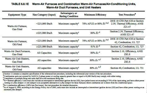
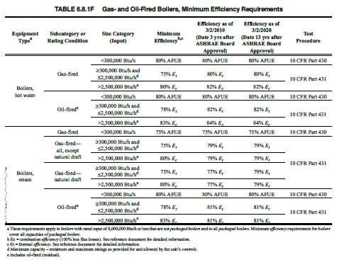
85 21
Technical Report Three
 Technical Report Three Existing Conditions for Mechanical Systems Contents Executive Summary...2 Building Overview...2 Mechanical Systems Overview...2 Mechanical System...3 Outdoor & Indoor Design Conditions...3
Table of Contents. List of Figures and Tables. Executive Summary: 3 ASHRAE Standard 62.1 Section 6 Analysis 7
 Army Reserve Center Newport, Rhode Island Technical Report One: ASHRAE Standard 62.1 Ventilat tion and Standard 90.1 Energy Design Evaluations October 4, 2010 2 Table of Contents Executive Summary: 3 ASHRAE
8 5.11: Finned-Tube Coils and Heat Exchangers : Humidifiers and Water Spray Systems : Access for Inspection, Cleaning, and Maintenance
 Table of Contents 3 Executive Summary 4 Building Overview 5 Mechanical Systems Overview 6 ASHRAE Standard 62.1 2013 Evaluation 6 Section 5: Systems and Equipment 6 5.1: Ventilation Air Distribution 6 5.2:
EADQUARTERS. Technical Report One. Stephanie Kunkel Mechanical Option
 EADQUARTERS 707 N. Calvert St. Technical Report One ASHRAE Standard 62.1 Ventilation ASHRAE Standard 90.1 Energy Design Stephanie Kunkel www.engr.psu.edu/ae/thesis/portfolios/2011/slk5061 Mechanical Option
Technical Assignment 1
 0 Technical Assignment 1 ASHRAE Standard 62.1 Ventilation and Standard 90.1 Energy Design Evaluations Compliance Analysis David H. Koch Institute for Integrative Cancer Research Massachusetts Institute
Architectural Engineering Senior Thesis Mechanical System Redesign
 Saint Joseph Medical Center Architectural Engineering Senior Thesis Mechanical System Redesign Chris Nicolais Building Description Existing Mechanical System Proposed Redesign Alternative Option Emergency
Mechanical Redesign, Proposal Elizabeth C. Krauss Mechanical Option September 18, 2013
 Mechanical Redesign, Proposal Elizabeth C. Mechanical Option September 18, 2013 State Institute of Rehabilitation T e c h n i c a l R e p o r t I 1 Mechanical Redesign, Proposal... 0 Executive Summary...
INTRODUCTION TO: ASHRAE STANDARD 90.1, HVAC System Requirements for Reducing Energy Consumption in Commercial Buildings
 INTRODUCTION TO: ASHRAE STANDARD 90.1, 2013 HVAC System Requirements for Reducing Energy Consumption in Commercial Buildings Rocky Mountain ASHRAE Technical Conference, April 29, 2016 SEAN BEILMAN, P.E.,
Hunter s Point South Intermediate School & High School
 Hunter s Point South Intermediate School & High School Long Island City, NY M E C H A N I C A L O P T I O N Technical Report One ASHRAE Standard 62.1-2007 and Standard 90.1-2007 Analysis By: Britt Kern
August 15, 2013 Page 1 of 19
 Section C401 Application Compliance with C402, C403, C404 and C405 AND (either C406.2, C406.3 or C406.4) Compliance with C402, C403, C404 or C405 Section C402 Building Envelope (Climate Zone 5A) Space-Conditioning
Technical Report 1. ASHRAE Standards 62.1, 170, and 90.1 Evaluation. Morton Hospital Expansion
 Technical Report 1 ASHRAE Standards 62.1, 170, and 90.1 Evaluation Morton Hospital Expansion Taunton, MA Courtney Millett Mechanical Option Advisor: Dr. Bahnfleth September 17, 2014 Millett Technical Report
UNIVERSITY OF MISSOURI Heating Ventilating and Air-Conditioning (HVAC) 2016 Q1
 2016 Q1") GENERAL: This section provides general standards for overall sizing and design of Heating, Ventilating, and Air Conditioning (HVAC) systems. Other sections contain specific standards for each system per
GENERAL: This section provides general standards for overall sizing and design of Heating, Ventilating, and Air Conditioning (HVAC) systems. Other sections contain specific standards for each system per
DIVISION 15 MECHANICAL
 DIVISION 15 MECHANICAL A. GENERAL DESIGN CONDITIONS 1. Design occupied spaces to maintain 72 F and a space dew point temperature not to exceed 55 F. 2. Design classroom and office space buildings with
Senior Thesis Centre Community Hospital East Wing Addition - Proposal Keith Beidel Mechanical Option 12/05/02 1
 Table of Contents Page Number(s) Executive Summary 2 Project Background 3 Proposed Depth Alternatives 4 Proposed Depth Redesign 5-7 Justification of Proposed Depth Redesign 8 Proposed Breath Redesign 9
Technical Report Rouse Boulevard. The Navy Yard Philadelphia, PA 19112
 Technical Report 1 201 Rouse Boulevard The Navy Yard Philadelphia, PA 19112 Nicholas W. Mattise Option: Mechanical;; Advisor: Dr. Miller September 23, 2013 Nicholas W. Mattise 1 of 22 Contents Executive
GARCIA GALUSKA DESOUSA Consulting Engineers
 L#57295/Page 1/July 21, 2017 HVAC SYSTEMS NARRATIVE REPORT The following is the HVAC system narrative, which defines the scope of work and capacities of the HVAC system as well as the Basis of Design.
2009 IECC Commercial Mechanical Requirements
 BUILDING ENERGY CODES UNIVERSITY 2009 IECC Commercial Mechanical Requirements Ken Baker PNNL-SA-66171 Learning(Objec-ves(( ( 1. Find(minimum(equipment(efficiency(requirements( and(recite(at(least(3(common(terms(for(measuring(
COMcheck Software Version Mechanical Compliance Certificate
 COMcheck Software Version 4.0.8.1 Mechanical Compliance Certificate Project Information Energy Code: Location: Climate Zone: Project Type: 90.1 (2013) Standard Buda, Texas 2a New Construction Construction
TECHNICAL REPORT 3 Mechanical Systems and Existing Conditions Northfield Mental Healthcare Center Northfield, Ohio
 Technical Report 3 Northfield Mental Healthcare Center Dr. Stephen Treado Ji Won Park Mechanical Option Fall 2012 TECHNICAL REPORT 3 Mechanical Systems and Existing Conditions Northfield Mental Healthcare
4. OVERVIEW OF MECHANICAL SYSTEM
 4. OVERVIEW OF MECHANICAL SYSTEM The 87,000 SF SLCC is served by six (6) Trane M-Series Climate Changer Air Handing Units (AHUs). Each unit serves a distinct zone within the facility that is unique in
COMcheck Software Version Review Mechanical Compliance Certificate
 COMcheck Software Version 4.0.7.2 Review Mechanical Compliance Certificate Section 1: Project Information Energy Code: 2014 Oregon Energy Efficiency Specialty Code Project Title: Benton County Health Project
Mechanical Compliance Certificate
 COMcheck Software Version 4.0.7.0 Mechanical Compliance Certificate Project Information Energy Code: Location: Climate Zone: Project Type: 90.1 (2013) Standard Austin, Texas 2a (weather data: TBD) New
Technical Assignment 3
 0 David H. Koch Institute for Integrative Cancer Research Senior Capstone Mechanical Option Technical Assignment 3 Mechanical Systems and Existing Conditions Report David H. Koch Institute for Integrative
COMcheck Software Version Mechanical Compliance Certificate
 COMcheck Software Version 3.8.2 Mechanical Compliance Certificate 90.1 (2007) Standard Section 1: Project Information Project Type: New Construction Project Title : Rudy's Star Motors Construction Site:
ASHRAE JOURNAL ON REHEAT
 Page: 1 of 7 ASHRAE JOURNAL ON REHEAT Dan Int-Hout Chief Engineer Page: 2 of 7 Overhead Heating: A lost art. March 2007 ASHRAE Journal Article Dan Int-Hout Chief Engineer, Krueger VAV terminals provide
Technical Investigation, Part Three Elizabeth C. Krauss Mechanical Option September 18, 2013
 Technical Investigation, Part Three Elizabeth C. Mechanical Option September 18, 2013 State Institute of Rehabilitation T e c h n i c a l R e p o r t I 1 Technical Investigation, Part Three... 0 Executive
ASHRAE/IESNA Standard
 ASHRAE/IESNA Standard 90.1-1999 An inside look at the requirements of Standard 90.1-1999 Energy Standard for Building Except Low-Rise Residential Building Mick Schwedler, PE Sr. Principal Applications
HVAC 101. H V A C S y s t e m s
 H V A C 1 0 1 S y s t e m s Introduction & Overview Should you care? Mechanical System Types Components & operation Popular Application Key Issues and Design Considerations System Comparisons First Cost
PINNACLE SERIES DEDICATED OUTDOOR AIR SYSTEM ENERGY EFFICIENT DEHUMIDIFICATION
 ENERGY EFFICIENT DEHUMIDIFICATION PINNACLE SERIES DEDICATED OUTDOOR AIR SYSTEM Provides a very high degree of latent cooling using only a minimal amount of conventional cooling input Substantial energy
B. Use UT Austin specifications and equipment schedule format for HVAC equipment where available.
 PART 1: GENERAL 1.01 General Requirements A. This standard is intended to provide useful information to the Professional Service Provider (PSP) to establish a basis of design. The responsibility of the
Computing Services Center
 Continuous Commissioning Report for the Computing Services Center Building #516 Submitted to: Utilities Energy Office Physical Plant Department Texas A&M University Prepared by: Energy Systems Laboratory
Union County Vocational - Technical Schools Scotch Plains, New Jersey
 SECTION 230593 - TESTING, ADJUSTING, AND BALANCING FOR HVAC PART 1 - GENERAL 1.1 SUMMARY A. Section Includes: 1. Balancing Air Systems: a. Constant-volume air systems. b. Variable-air-volume systems. 2.
1.1 This section applies to air handling units for HVAC Systems.
 AIR HANDLING UNITS GENERAL INFORMATION 1.1 This section applies to air handling units for HVAC Systems. DESIGN REQUIREMENTS 2.1 Design Criteria a. The decision to use modular central station air handling
F.W. Olin Physical Science Laboratory
 Mechanical Systems Existing Conditions Evaluation Presented on Page 1 of 16 Table of Contents Executive Summary Depth p.3 Executive Summary Breadth p.4 Introduction & Background p.5 Alternatives p.7 Breadth
AIR-CONDITIONING SYSTEMS AND APPLICATIONS. Abdullah Nuhait Ph D. King Saud University
 AIR-CONDITIONING SYSTEMS AND APPLICATIONS Abdullah Nuhait Ph D. King Saud University AIR-CONDITIONING SYSTEMS Earliest air conditioning system used only for heating (winter) Provided heated air for comfort
2009 Washington State Non-Residential Energy Code Scott Rushing, PE, LEED AP - Rushing Company Lisa Rosenow, CSBA, LEED AP NEEC
 2009 Washington State Non-Residential Energy Code Scott Rushing, PE, LEED AP - Rushing Company Lisa Rosenow, CSBA, LEED AP NEEC Mechanical Systems Agenda Changes in NREC Chapter 11 Changes in NREC Chapter
TECHNICAL REPORT 3: Mechanical Systems and Existing Conditions. Michael Morder Mechanical Option Advisor: Dr. William Bahnfleth
 TECHNICAL REPORT 3: Mechanical Systems and Existing Conditions Michael Morder Mechanical Option Advisor: Dr. William Bahnfleth INOVA South Patient Tower Falls Church, VA November 16, 2011 Table of Contents
Appendix B. Facilities Assessment Report
 Mile Lane Army Reserve Center Redevelopment Plan September 2008 Appendix B Facilities Assessment Report RKG Associates, Inc. Mile Lane Army Reserve Base Middletown, CT MEP System Evaluation For RKG Associates
Retrocommissioning Findings Summary: Building X #1 Priority: Major Comfort/Control Problems
 IMPORTANT NOTICE: This sample document is provided for instructional purposes only. CCC is not rendering advice concerning any commission project or practices. This document is neither approved nor intended
Mechanical Technical Report 1. ASHRAE Standard 62.1 Ventilation Compliance Evaluation
 Mechanical Technical Report 1 Standard 62.1 Ventilation Compliance Evaluation Lutheran Theological Seminary at Philadelphia The New Learning Center Prepared For: William P. Bahnfleth, Ph.D., P.E. Department
City of Duluth Festival Center 04/25
 SECTION 230593 - TESTING, ADJUSTING, AND BALANCING FOR HVAC PART 1 - GENERAL 1.1 RELATED DOCUMENTS A. Drawings and general provisions of the Contract, including General and Supplementary Conditions and
CARRIER edesign SUITE NEWS. Modeling 100% OA Constant Volume Air Systems. Volume 6, Issue 1. Page 1 Modeling 100% OA Constant Volume Air Systems
 Volume 6, Issue 1 CARRIER edesign SUITE NEWS Modeling 100% OA Constant Volume Air Systems This article provides an overview of how to model a stand-alone constant air volume (CAV) 100% OA system in HAP.
Energy Savings Potential of Passive Chilled Beam System as a Retrofit Option for Commercial Buildings in Different Climates
 Purdue University Purdue e-pubs International High Performance Buildings Conference School of Mechanical Engineering 2014 Energy Savings Potential of Passive Chilled Beam System as a Retrofit Option for
Gil Rossmiller. In the construction industry for over 30 years. ICC IRC Plumbing & Mechanical Code Development Committee
 Gil Rossmiller In the construction industry for over 30 years ICC IRC Plumbing & Mechanical Code Development Committee ICC- IECC Commercial Energy Code Development Committee Building Official Parker, Colorado
Challenges and Methods of Estimating a Conceptual HVAC Design
 Challenges and Methods of Estimating a Conceptual HVAC Design ABSTRACT In any conceptual HVAC design, estimators are faced with the challenge of trying to capture all of the pieces that complete a system.
Dehumidifying with Dedicated Outdoor Air
 Dehumidifying with Dedicated Outdoor Air System Configurations Figure 71. Configurations for dedicated outdoor-air systems A dedicated outdoor-air handler separately filters, cools, dehumidifies, heats,
Terminal. Las Vegas, NV. Technical
 McCarran International port Terminal 3 Technical Assignment 3 Mechanical System Existing Conditions Evaluation December 3, 2007 Prepared By: Faculty Advisor: Dr. William Bahnfleth, Ph.D., P..E. Table of
CONTENTS. B. System Design and Performance Requirements
 15625 Water Chillers This document provides design standards only, and is not intended for use, in whole or in part, as a specification. Do not copy this information verbatim in specifications or in notes
Element Z General Design Requirements Existing Facilities Information
 PART 1 - INTRODUCTION 1.01 OVERVIEW A. This Section provides general information for building systems and components. B. Refer to the Owner s Design Guideline Elements A though G and Element Z for technical
Christopher Kelly Technical Report Three
 Christopher Kelly Technical Report Three Mechanical Systems and Existing Conditions Evaluation SALK HALL ADDITION The University of Pittsburgh, Pittsburgh Christopher Kelly, Mechanical Option Professor
1080 Marina Village Parkway, Suite 501 Alameda, CA (510) Fax (510) HVAC DESIGN INTENT
 Fax (510) HVAC DESIGN INTENT") Taylor Engineering 1080 Marina Village Parkway, Suite 501 Alameda, CA 94501-1142 (510) 749-9135 Fax (510) 749-9136 LLC HVAC DESIGN INTENT PART 1 - GENERAL 1.1 Overview A. The project consists of a 3-story
Taylor Engineering 1080 Marina Village Parkway, Suite 501 Alameda, CA 94501-1142 (510) 749-9135 Fax (510) 749-9136 LLC HVAC DESIGN INTENT PART 1 - GENERAL 1.1 Overview A. The project consists of a 3-story
Job Name Control Systems Description Date
 Job Name Control Systems Description Date Project Overview The project is a describe the building and its major HVAC systems (e.g. three-story office building, served by a rooftop unit VAV system ). In
HVAC 101. The Basics of Heating, Ventilation and Air Conditioning
 HVAC 101 The Basics of Heating, Ventilation and Air Conditioning HVAC Heating, Ventilation and Air Conditioning Provides comfort for people Allows humans to exist under adverse conditions. Comfort Comfort
Civil Engineering Building
 Continuous Commissioning Report For the Civil Engineering Building Building 492 Submitted to: Utilities Energy Office Physical Plant Department Texas A&M University Prepared by: Energy Systems Laboratory
COMcheck Software Version Mechanical Compliance Certificate
 COMcheck Software Version 4.0.3.0 Mechanical Compliance Certificate Section 1: Project Information Energy Code: 2014 Oregon Energy Efficiency Specialty Code Project Title: AHSC (Asian Heal Service Center
High Performance Building Guide 1
 Description This Guide is intended to be used for projects with a Vermont Certified: High Performance energy efficiency goal. This High Performance goal is a whole-building efficiency approach rather than
Inspection Phase Three. Mechanical, Electrical & Plumbing Section 503
 Inspection Phase Three Mechanical, Electrical & Plumbing Section 503 COMCheck Mechanical Field Inspection Checklist Mechanical Mechanical, Electrical & Plumbing Equipment Efficiencies But a lot ore too
Existing Mechanical System Operation
 majority of the air handlers. There are louvers along the north side of the building that allow for outdoor air to come in and feed the air handlers. On levels 4-8 the research laboratories are variable
Energy-Efficient Makeup Air Units BY HUGH CROWTHER, P.ENG., MEMBER ASHRAE
 This article was published in ASHRAE Journal, March 20145 Copyright 2015 ASHRAE. Posted at www.ashrae.org. This article may not be copied and/or distributed electronically or in paper form without permission
Tighe&Bond. Groton Heights School Mechanical Evaluation. 1 Existing Conditions. 1.1 Water Service Entrance
 Groton Heights School Mechanical Evaluation TO: FROM: Amy Vaillancourt, Project Manager Harley Langford, Project Manger Jason Curtis, P.E. DATE: February 24, 2016; Revised May 31, 2016 On Monday, December
Element Z General Design Requirements Existing Facilities Information
 Charles M. LeMaistre PART 1 - INTRODUCTION 1.01 OVERVIEW A. This Section provides general information for building systems and components. B. Refer to the Owner s Design Guideline Elements A though G and
ENGINEERING BULLETIN. Overview of Chilled Beam Technology. Purpose. Summary. Theory
 Overview of Chilled Beam Technology Purpose Chilled beam technology is new to the United States but has been used in Europe since the 1950 s. Chilled beams can reduce energy costs, improve indoor air quality,
HAP e-help. Modeling Induction Beams in HAP v4.8 QB TIP 001
 This HAP e-help provides a high-level overview of induction beams, how they work and how to model them in HAP 4.8 (and later versions). The first half of the article explains how induction beams work.
Cleveland Clinic Design Standards MECHANICAL SYSTEMS DESIGN GUIDELINES HVAC AIR DISTRIBUTION PART I - GENERAL 1.1 SUMMARY
 PART I - GENERAL 1.1 SUMMARY A. This section addresses the general requirements for air handling distribution systems, including air handlers, ductwork, ductwork accessories, terminal units, air devices,
7. MECHANICAL SYSTEM DESIGN
 7. MECHANICAL SYSTEM DESIGN The second primary topic of this thesis is to investigate the application of a dedicated outdoor air system (DOAS) to the SLCC. The stated goals for this thesis of improved
CALIFORNIA MECHANICAL CODE OVERVIEW OF 2016 UPDATES CHANGES AND RAMIFICATIONS
 CALIFORNIA MECHANICAL CODE OVERVIEW OF 2016 UPDATES CHANGES AND RAMIFICATIONS Presented to: Presented by: Sargon Ishaya, PE www.pragmaticprofessionalengineers.com Introduction Today s Agenda Overview Review
The Creative and Performing Arts High School (CAPA) Pittsburgh, PA 11/11/2002 Andrew Tech Mechanical Option Prof. S. A. Mumma
 Pittsburgh, PA 11/11/2002 Andrew Tech Mechanical Option Prof. S. A. Mumma") Objectives and Requirements For the Creative and Performing Arts High School (CAPA), the main objective of the mechanical design is to provide an energy efficient system that is easily maintainable and
Objectives and Requirements For the Creative and Performing Arts High School (CAPA), the main objective of the mechanical design is to provide an energy efficient system that is easily maintainable and
2006 Washington State Nonresidential Energy Code Compliance Form Washington State Nonresidential Energy Code Compliance Forms Revised July 2007
 Mechanical Summary 2006 Washington State nresidential Energy Code Compliance Form MECH-SUM 2006 Washington State nresidential Energy Code Compliance Forms Revised July 2007 Project Info Project Address
HONORABLE MENTION: COMMERCIAL BUILDINGS, EXISTING
 ASHRAE s BEST This article was published in ASHRAE Journal, November 2010. Copyright 2010 American Society of Heating, Refrigerating and -Conditioning Engineers, Inc. Reprinted here by permission from
WORKSHOP VENTILATION- PSYCHROMETRICS-AHU
 Alkis Triantafyllopoulos Mechanical Engineer Member TEE, MASHRAE a.trianta@gmail.com WORKSHOP VENTILATION- PSYCHROMETRICS-AHU Based on ASHRAE 62 Purpose Set minimum Outdoor Air ventilation Rates Air Quality
APPLICATION GUIDE BEAMS
 BEAMS There is an increasing need for energy efficient air conditioning systems as energy codes become more stringent. Chilled beam systems are one such alternate to traditional all air conditioning systems.
SESSION Michigan Energy Code (MEC) Update (3 Technical) Per SMACNA Standard (TAB, Duct Design) and ASHRAE ( ) ASHRAE Detroit Members:
 Update (3 Technical) Per SMACNA Standard (TAB, Duct Design) and ASHRAE ( ) ASHRAE Detroit Members:") SESSION 1-2015 Michigan Energy Code (MEC) Update (3 Technical) Per SMACNA Standard (TAB, Duct Design) and ASHRAE (90.1.2013) ASHRAE Detroit Members: AM Session is eligible for (X) Professional Development
SESSION 1-2015 Michigan Energy Code (MEC) Update (3 Technical) Per SMACNA Standard (TAB, Duct Design) and ASHRAE (90.1.2013) ASHRAE Detroit Members: AM Session is eligible for (X) Professional Development
SECTION PACKAGED, OUTDOOR, CENTRAL-STATION AIR-HANDLING UNITS
 SECTION 237413 - PACKAGED, OUTDOOR, CENTRAL-STATION AIR-HANDLING UNITS PART 1 - GENERAL 1.1 SUMMARY A. This Section includes packaged, outdoor, central-station air-handling units (rooftop units) with the
Mechanical System Redesign. Dedicated Outdoor Air System. Design Criteria
 Mechanical System Redesign Dedicated Outdoor Air System Design Criteria The outdoor air conditions used were for Philadelphia, Pennsylvania IAP at a 0.4% occurrence. The supply air conditions were developed
AIR DISTRIBUTION. C. Section Building Automation and Control System Guidelines. D. Section Fire Alarm System & Detection Systems
 233100 AIR DISTRIBUTION PART 1: GENERAL 1.01 RELATED SECTIONS A. Section 230700 HVAC Insulation B. Section 237300 Air Handling C. Section 230900 Building Automation and Control System Guidelines D. Section
COMcheck Software Version Interior Lighting Compliance Certificate
 Section 1: Project Information Energy Code: 2009 IECC Project Type: New Construction COMcheck Software Version 4.0.2.8 Interior Lighting Compliance Certificate Construction Site: Owner/Agent: Designer/Contractor:
ASHRAE WILL GIVE YOU THE WORLD. This ASHRAE Distinguished Lecturer is brought to you by the Society Chapter Technology Transfer Committee
 ASHRAE WILL GIVE YOU THE WORLD This ASHRAE Distinguished Lecturer is brought to you by the Society Chapter Technology Transfer Committee Complete the Distinguished Lecturer Event Summary Critique CTTC
Raised Access Floor - (AE Breadth Area)
") Raised Access Floor - (AE Breadth Area) Currently, the Plaza has a raised access flooring system on both the 7 th and 8 th floors. The 8 th floor is designed with an independent HVAC system utilizing an
Raised Access Floor - (AE Breadth Area) Currently, the Plaza has a raised access flooring system on both the 7 th and 8 th floors. The 8 th floor is designed with an independent HVAC system utilizing an
ERRATA SHEET FOR ANSI/ASHRAE/IES STANDARD (I-P Edition) Energy Standard for Buildings Except Low-Rise Residential Buildings.
 Energy Standard for Buildings Except Low-Rise Residential Buildings.") ERRATA SHEET FOR ANSI/ASHRAE/IES STANDARD 90.1-2013 (I-P Edition) Energy Standard for Buildings Except Low-Rise Residential Buildings July 7, 2017 The corrections listed in this errata sheet apply to ANSI/ASHRAE/IES
ERRATA SHEET FOR ANSI/ASHRAE/IES STANDARD 90.1-2013 (I-P Edition) Energy Standard for Buildings Except Low-Rise Residential Buildings July 7, 2017 The corrections listed in this errata sheet apply to ANSI/ASHRAE/IES
AIRSIDE COMPONENTS AND SYSTEMS
 Ventilation: Outdoor air (OA) ventilation shall be introduced into each occupied building space in compliance with ASHRAE Standard 62. Adequate additional OA capability is needed to keep buildings under
FAARM-Underground Facility. Conceptual Design Review. Mechanical Systems. Dunham Associates, Inc.
 FAARM-Underground Facility Conceptual Design Review Mechanical Systems Prepared by: Dunham Associates, Inc. April 17, 2012 Dunham Project Number: 0412145-000-00 Dunham Associates Inc. Page 1 of 8 Mechanical
THIS IS A DESIGN GUIDE NOT A SPECIFICATION. Montgomery County Public Schools Facilities Guide DIVISION 15 MECHANICAL
 SECTION 15100 PART 1 GENERAL THIS IS A DESIGN GUIDE NOT A SPECIFICATION Montgomery County Public Schools Facilities Guide DIVISION 15 MECHANICAL HVAC SYSTEMS APPLICATIONS 1.1 SCOPE: The intent of this
Topic 2. ME 414/514 HVAC Systems Overview Topic 2. Equipment. Outline
 ME 414/514 HVAC Systems Overview Equipment Outline 2-1 The Complete System 2-2 The Air-Conditioning and Distribution System 2-3 Mechanical Equipment Air-handling Equipment Heating Equipment Boilers Furnaces
Brown University Revised August 3, 2012 Facilities Design & Construction Standards SECTION AIR HANDLING UNITS
 SECTION 23 70 00 AIR HANDLING UNITS PART 1. GENERAL 1.1 Section includes air-handling units to 15,000 cfm and accessories. 1.2 Related Sections 1 : A. Division 01 - Brown University Standard for Narragansett
COMMERCIAL HVAC PACKAGED EQUIPMENT. Rooftop Units Level 1: Constant Volume
 COMMERCIAL HVAC PACKAGED EQUIPMENT Rooftop Units Level 1: Constant Volume Technical Development Programs (TDP) are modules of technical training on HVAC theory, system design, equipment selection and application
2012 INTERNATIONAL FUEL GAS CODE VENTS
 2012 INTERNATIONAL FUEL GAS CODE SECTION 502 (IFGC) VENTS 502.1 General. All vents, except as provided in Section 503.7, shall be listed and labeled. Type B and BW vents shall be tested in accordance with
Ventilation for New Low-Rise Residential Buildings July 20, 2015
 Ventilation for New Low-Rise Residential Buildings July 20, 2015 BSC Standard 01 2015 Building Science Corporation 3 Lan Drive, Suite 102 Westford, MA 01886 www.buildingscience.com Contents 1. PURPOSE...3
Mechanical Technical Report 3. Mechanical Systems Existing Conditions Evaluation
 Mechanical Technical Report 3 Lutheran Theological Seminary at Philadelphia The New Learning Center Prepared For: William P. Bahnfleth, Ph.D., P.E. Department of Architectural Engineering Pennsylvania
SECTION HVAC TABLE OF CONTENTS PART 1 - SYSTEM DESCRIPTION / OUTLINE SPECIFICATIONS FILED SUB BID PROJECT OVERVIEW...
 SECTION 230001 TABLE OF CONTENTS SECTION 230001 PART 1 - SYSTEM DESCRIPTION / OUTLINE SPECIFICATIONS... 1 1.00 FILED SUB BID... 1 1.01 PROJECT OVERVIEW... 2 1.02 DESIGN CRITERIA... 4 1.03 CODE ISSUES...
COMMERCIAL HVAC EQUIPMENT Coils: Direct Expansion, Chilled Water, and Heating
 COMMERCIAL HVAC EQUIPMENT Coils: Direct Expansion, Chilled Water, and Heating Technical Development Program Technical Development Programs (TDP) are modules of technical training on HVAC theory, system
ASHRAE Illinois Chapter 2015 Excellence in Engineering Awards
 ASHRAE Illinois Chapter 2015 Excellence in Engineering Awards PROJECT Chicago Vocational Career Academy Chicago, Illinois OWNER Chicago Public Schools PREPARED FOR American Society of Heating Refrigerating
COMMERCIAL HVAC EQUIPMENT Indoor Self-Contained Units
 COMMERCIAL HVAC EQUIPMENT Indoor Self-Contained Units Technical Development Program Technical Development Programs (TDP) are modules of technical training on HVAC theory, system design, equipment selection
A. Base Bid: 1. Heating Contractor provide: a. Control sequences for HVAC systems, subsystems, and equipment.
 SECTION 23 09 93 - SEQUENCE OF OPERATIONS FOR HVAC CONTROLS PART 1 - GENERAL 1 WORK INCLUDES A. Base Bid: Heating Contractor provide: Control sequences for HVAC systems, subsystems, and equipment. B. Alternate
Technical Report #3 Mechanical Systems Existing Conditions Evaluation
 Mechanical Option Technical Report #3 Technical Report #3 Mechanical Systems Existing Conditions Evaluation Instructor: Dr. Bahnfleth 11.15.04 Building Sponsor: CCG Facilities Integration Table of Contents
COMMERCIAL HVAC SYSTEMS Water Source Heat Pump Systems
 COMMERCIAL HVAC SYSTEMS Water Source Heat Pump Systems Technical Development Program Technical Development Programs (TDP) are modules of technical training on HVAC theory, system design, equipment selection
GUIDELINES FOR HIGHRISE BUILDING CONSTRUCTION PROJECTS (MECHANICAL VENTILATION)
") GUIDELINES FOR HIGHRISE BUILDING CONSTRUCTION PROJECTS (MECHANICAL VENTILATION) February, 2017 Contents Clauses Page 1. Basic Concepts 1 2. Design Considerations 1 3. Car Parks Ventilation 2 4. Kitchen
GUIDELINES FOR HIGHRISE BUILDING CONSTRUCTION PROJECTS (MECHANICAL VENTILATION) February, 2017 Contents Clauses Page 1. Basic Concepts 1 2. Design Considerations 1 3. Car Parks Ventilation 2 4. Kitchen
VH Series B ENVIRO-STAC Vertical Hi-Rise Fan Coil Unit with Enhanced Humidity Control
 VH Series B ENVIRO-STAC Vertical Hi-Rise Fan Unit with Enhanced Humidity Control Motorized Bypass Damper Temperature and Humidity Controller Reheat Control Elastomeric Foam Insulation High Efficiency,
National Institutes of Health Building 37 Modernization Bethesda, Maryland MECHANICAL DEPTH EXISTING MECHANICAL SYSTEM
 MECHANICAL DEPTH EXISTING MECHANICAL SYSTEM The need to maintain occupancy during the renovation and the strict NIH Design Guidelines were the main driving forces behind the design. The mechanical engineering
System Components with ` Emphasis on Packaged Rooftop Application and Installation. Jerry Cohen President Jacco & Assoc.
 System Components with ` Emphasis on Packaged Rooftop Application and Installation Jerry Cohen President Jacco & Assoc. Agenda Define and relate in practical terms the following components: System Effect
CHAPTER 4. HVAC DELIVERY SYSTEMS
 CHAPTER 4. HVAC DELIVERY SYSTEMS 4.1 Introduction 4.2 Centralized System versus Individual System 4.3 Heat Transfer Fluids 4.4 CAV versus VAV Systems 4.5 Common Systems for Heating and Cooling 4.6 Economizer