SP22 Series Self-Priming Pumps. Assembly, Installation and Operation Manual
|
|
|
- Rosemary McBride
- 6 years ago
- Views:
Transcription

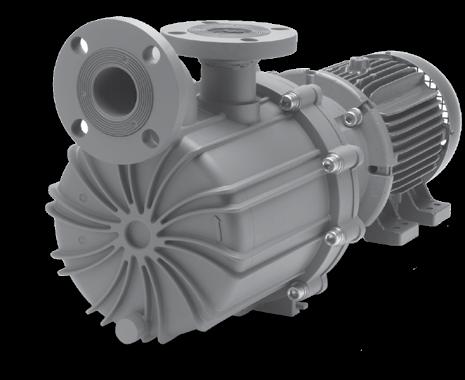


1 SP22 Series Self-Priming Pumps Assembly, Installation and Operation Manual
2 TABLE OF CONTENTS Important Notice Chemical Reaction Disclaimer Safety Precautions 3 SP22 Capabilities 4 SP22 Prime Time Curves 5 Section I - Assembly Pumps with Motors 6 Pumps without Motors 6 Section II - Installation..7 Mounting 7 Motor/Electrical 8 Section III - Start-up and Operation 8 Section IV - Shut Down Flush Systems..8 Maintenance 9 Section V - Disassembly 9-12 Outer Drive Replacement 11 Impeller Thrust Ring 11 Impeller Bushing 11 Impeller Disassembly Reassembly SP22 Part Number Explanation 13 Spare Parts Diagram 14 Spare Parts List Section VI - Troubleshooting 19 Section VII - Warranty 19 NOTE: Maintenance videos are now available on line at FTI Contacts: Tech Service: ; techservice@finishthompson.com Order Fax: or Sales: (toll free U.S. and Canada; ) 2
3 IMPORTANT NOTICE U.S. Export Administration Regulations, pursuant to ECCN 2B350, prohibit the export or reexport to certain enumerated countries of sealless centrifugal pumps in which all wetted materials are constructed from fluoropolymers without first applying for and obtaining a license from the U.S. Bureau of Industry and Security (BIS). This affects all Finish Thompson magnetic-drive pumps constructed from PVDF or lined with ETFE. Please contact the BIS ( or Finish Thompson with questions regarding the Regulations or a list of the countries to which they apply. Chemical Reaction Disclaimer The user must exercise primary responsibility in selecting the product s materials of construction, which are compatible with the fluid(s) that come(s) in contact with the product. The user may consult Finish Thompson, Inc. (manufacturer) and a manufacturer s representative/distributor agent to seek a recommendation of the product s material of construction that offers the optimum available chemical compatibility. However neither manufacturer nor agent shall be liable for product damage or failure, injuries, or any other damage or loss arising out of a reaction, interaction or any chemical effect that occurs between the materials of the product s construction and fluids that come into contact with the product s components. Safety Precautions WARNING: READ THIS MANUAL COMPLETELY BEFORE INSTALLING AND OPERATING THIS UNIT. FAILURE TO FOLLOW THESE PRECAU- TIONS CAN RESULT IN SERIOUS INJURY OR DEATH. WARNING: Magnetic field hazard. This pump contains powerful magnets. Exposed magnets (pump not connected to motor produce powerful magnetic fields. Individuals with cardiac pacemakers, implanted defibrillators, other electronic medical devices, metallic prosthetic heart valves, internal wound clips (from surgery), metallic prosthetic devices or sickle cell anemia must not handle or be in the proximity of the magnets contained inside the pump. Consult a health care provider for specific recommendations before working with this pump. WARNING: The SP Series are not recommended for pumping flammable or combustible liquids (unless pump is manufactured with ATEX construction and installed in compliance with all applicable ATEX standards). During the priming process, the pump atmosphere can become very dangerous should the pump fail to prime and overheat. SP Series pumps can be used to pump non-flammable or non-combustible liquids in a hazardous area. However, it is important to follow these guidelines: 1. You must select the non-sparking (Ns) bronze bump ring option. The non-sparking ring is pressed into the clamp ring or motor adapter and prevents sparking should the motor bearings fail and the outer mag drive assembly runs out of round. 2. You must select an FTI explosion-proof motor or provide your own explosion-proof motor. 3. Contact Finish Thompson for more information about using pump in ATEX areas. WARNING: Magnetic force hazard. This pump should only be disassembled and assembled using the recommended procedures. The magnetic attraction is powerful enough to rapidly pull the motor end and the wet end together. Do not place fingers between the mating surfaces of the motor and wet ends to avoid injuries. Keep the drive magnet and impeller assembly away from metal chips or particles, items with magnetic stripes like credit cards and magnetic computer media such as floppy discs and hard drives. WARNING: Hot surfaces. This pump is capable of handling liquids with temperatures as high as 220º F (104º C). This may cause the outer areas of the pump to become hot as well and could cause burns. WARNING: Rotating Parts. This pump has components that rotate while in operation. Follow local safety standards for locking out the motor from the power supply during maintenance or service. WARNING: Chemical Hazard. This pump is used for transferring many types of potentially dangerous chemicals. Always wear protective clothing, eye protection and follow standard safety procedures when handling corrosive or personally harmful materials. Proper procedures should be followed for draining and decontaminating the pump before disassembly and inspection of the pump. There may be small quantities of chemicals present during inspection. WARNING: Never run pump at less than minimum flow or with the discharge valve closed. This could lead to pump failure. WARNING: The pump and associated components are heavy. Failure to properly support the pump during lifting and movement could result in serious injury or damage to the pump and components. CAUTION: This pump should never be started without the 2 1/2 gallons (9.5 liters) of priming fluid in the housing. If the pump has a PTFE, ceramic or silicon carbide bushing, IT CANNOT BE RUN DRY WITHOUT CAUSING DAMAGE TO THE PUMP. However, the pump can operate without liquid in the housing if the pump has a carbon bushing. The exact length of time the pump can operate dry with a carbon 3
4 bushing varies with operating conditions and environment. CAUTION: Never start or operate with a closed suction valve. WARNING: Operation without priming or against a closed discharge valve can result in high temperatures that can result in injury or damage to pump components. CAUTION: Always provide adequate NPSHa (net positive suction head available). It is recommended to provide at least 2 feet (61 cm) above the NPSHr (net positive suction head required). CAUTION: If pump is used on variable speed drive, do not exceed the frequency for which the pump was designed (for example, if the pump is a 50 Hz model, do not exceed 50 Hz). SP22 Capabilities Maximum Working Pressure: 90 psi (6.2 bar) Maximum Temperature: Polypropylene -180º F (82º C); PVDF 220º F (104º C) NOTE: Maximum temperature is application dependent. Consult a chemical resistance guide or the chemical manufacturer for chemical compatibility and temperature limits. Maximum Lift: 25 feet (7.6 meters) NOTE: Lift determined on fresh, cold water with 3 Schedule 40 pipe. Specific gravity affects lift capability. Divide 25 feet (7.6 meters) by the specific gravity to determine equivalent maximum lift. Solids: Maximum particle size is 100 microns for slurries and 1/64 (.4 mm) for occasional solids. Maximum hardness is 80 HS. Maximum concentration is 10% by weight. If solids are being pumped, it is recommended that the pump have silicon carbide components for best results. Pumping solids may lead to increased wear. NOTE: While the pump is capable of being used in sump applications, it is NOT a trash pump. Care must be taken to ensure that debris and foreign objects do not enter the pump or damage may result. FTI recommends using a 2 (50.8 mm) or 3 (76.2 mm) strainer basket with 1/8 (3.2 mm) perforations. Regular strainer basket maintenance is required to prevent plugging and a decrease in NPSHa so not to starve and damage the pump. Minimum Allowable Flow Rate Do not allow the flow rate to drop below the minimum flow rate in the chart below: 3450/2900 rpm 1750/1450 rpm 10 US gpm (2.3 m 3 /hr) 5 US gpm (1.1 m3 /hr) Maximum Allowable Motor Power Do not exceed 7.5 kw (10 horsepower) for 50 Hz, 2900 rpm applications. For 60 Hz, 3450 rpm applications, the pump is capable of starting a 15 horsepower motor but is limited to a maximum of 13 horsepower (9.7 kw) while running. Use the information in the chart below to determine the maximum specific gravity capabilities by impeller trim for non-overloading applications. The use of a power monitor is strongly recommended for 60 Hz applications above 10 horsepower (7.5 kw). Maximum Noise Level: 80 dba (pump only) Maximum Specific Gravity for Non-Overloading Applications 3450 rpm (60 Hz) Impeller Diameter Maximum Specific Gravity 7 (177.8 mm) (165.1 mm) (152.4 mm) (139.7 mm) (127.0 mm) 1.8 Impeller Diameter 2900 rpm (50 Hz) Maximum Specific Gravity mm (7 ) mm (6.5 ) mm (6 ) mm (5.5 ) mm (5 ) 1.8 4
5 Priming Liquid Volume Initial filling (or refilling after maintenance) of the pump housing requires (2 1/2) US gallons (9.5 liters) of liquid. Priming Time Priming time varies with the impeller diameter and speed. 5
 Pumps with Motors Proceed to")

 in the groove in the motor adapter.")
 on the motor face. Align the holes in the adapter with the holes in the motor face. See figure 1.")
6 Unpacking and Inspection Unpack the pump and examine for any signs of shipping damage. If damage is detected, save the packaging and notify the carrier immediately. Section I - Assembly Tools Required: 3/8 Allen wrench or ballpoint hex socket, 3/16 Allen wrench, 10 mm hex socket, metric socket set (for pumps with IEC outer drives) Pumps with Motors Proceed to Installation Section Pumps Without Motors NOTE: All motors must have motor feet. 1. Remove the pump, drive magnet assembly and hardware package from the carton. CAUTION: Keep away from metallic particles, tools and electronics. Drive magnets MUST be free of metal chips. WARNING: Keep the drive magnet away from the open end of the motor adapter and barrier. Strong magnetic attraction could allow the drive hub to enter the motor adapter resulting in injury or damage. 2. For 184TC motors, proceed to step 3. For 213/215 NEMA motors only Install the o-ring (item 14A) in the groove in the motor adapter. Use small amount of petroleum jelly (or silicone grease on EPDM o-rings) to help hold the o-ring in Figure 1 place. Install the larger female rabbet portion of the motor adapter flange (item 14) on the motor face. Align the holes in the adapter with the holes in the motor face. See figure 1. For IEC 90, 100/112, 132 with B5 flange motors - Install flange (item 14) on motor with pockets (depressions) side towards the motor face. Align (4) holes in the adapter with the holes in the motor face. install the (4) bolts, lock washers and flat washers through the motor adapter into the motor face. See figure 1. Note: B5 flange motors require customer supplied hardware. Flange hole thread size: 90 B5 = M10 x /112 B5 = M12 x B5 = M12 x 1.75 SP22 Assembly, Installation and Operation towards the motor face. Align (4) holes in the adapter with the holes in the motor face. Install (4) bolts, lock washers and flat washers (items 24, 25, 26) through the motor adapter into the motor face. See figure 1. For 100/112 with B14 flange motors Install flange (item 10) on motor with pockets (depressions) towards the pump motor adapter (item 8). Align (4) holes in the adapter with the holes in the motor face. Install (4) bolts, lock washers and flat washers (items 20, 21, 22) through the motor adapter into the motor face. Torque bolts to the following: 90/100/112 B14 frame (M8) = 130 in-lb (14.7 N-m) 132 B14 (M10) frame (M10) = 240 in-lb (27.1 N-m) 90 frame B5 (M10) = 240 in-lb (27.1 N-m) 100/112/132 B5 (M12) = 480 in-lb (54.3 N-m) 3. Coat the motor shaft with anti-seize compound. Insert key supplied with motor into keyway on motor shaft. NOTE: Make sure the motor shaft is clean and free of burrs. The outer drive is precision machined and has a bore tolerance of /-0 inch. 4. Slide the outer drive magnet assembly (item 13) onto the motor shaft until the motor shaft contacts the snap ring in the bore of the drive. Figures 2 and 3. Figure 2 Figure 3 WARNING: Be careful, magnets will try to attract tools. Metric Motors: Secure the drive to the motor shaft using bolt, lock washer and flat washer (items 21, 22, 23). Thread the bolt into the end of the motor shaft (while holding the outer drive to prevent it from turning). See figure 4. Tighten the bolt to the following: 90 frame (M8) = 130 in-lb (14.7 N-m) 100/112 frame (M10) = 240 in-lb (27.1 N-m) 132 frame (M12) = 480 in-lb (54.3 N-m) NEMA Motors: Install set screws (item 13B) into threaded holes on the side of the outer drive magnet assembly. Using a 3/16 Allen wrench, tighten to 228 in-lbs (25.8 N-m). See figure 5. For 90 & 132 with B14 flange & 145TC motors - Install the flange item 14) on motor with pockets (depressions) side 6 Figure 4 Figure 5
 in the groove in the motor adapter (motor end).")
.")
 or the motor adapter flange. See figures 6 and 7.")
7 NOTE: The clearance between the motor adapter and drive magnet is tight (about.010 /.254 mm). 5. Install the pump end on the motor/drive magnet assembly. For 182, 184, 213 and 215TC motor frame pumps, install the o-ring (item12b) in the groove in the motor adapter (motor end). Use a small amount of petroleum jelly (or silicone grease on EPDM o-rings) to help hold the o-ring in place. Total suction lift including pipe friction loss and corrections for specific gravity must not exceed 25 feet (7.6 meters). Contact FTI for pumps installed where the elevation exceeds 1,000 feet (305 meters). Place the motor/drive on the floor with the drive and motor face pointing up. Firmly grab the pump and slide over the outer drive magnet until the motor adapter is seated in the rabbet of the motor (184TC) or the motor adapter flange. See figures 6 and 7. The last 4-5 (10-12 cm) will have strong magnetic attraction between the pump and outer drive magnet. 6. Secure the pump to the motor using (4) 1/2 socket head Install the pump as close to the suction source as possible. SP Series pumps are designed to operate in a horizontal position only with discharge on the top. Figure 6 Figure 7 cap screws, lock washers and flat washers (items 18, 19, 20). Use 3/8 Allen wrench or 3/8 ballpoint hex socket on universal joint. See figures 8 and Rotate the motor fan to ensure that there is no binding in the pump. SP Series pumps self-priming capability is due to its ability to create a vacuum in the suction piping. The suction piping MUST be airtight at fittings and connections. Support the piping independently near the pump to eliminate any strain on the pump casing. In addition, the piping should be aligned to avoid placing stress on the pump casing. The suction side of the pump should be as straight and short as possible to minimize pipe friction. Figure 8 Figure 9 8. Proceed to Installation Section. Section II - Installation Mounting Pump foot should be securely fastened to a solid foundation. If the pump was received with plastic shipping shims, these may be used as additional support for the motor feet. CAUTION: The NPSH available to the pump must be greater than the NPSH required. The amount of lift, frictional pipe loss and vapor pressure must be calculated into the application. NPSH available should be two feet (.6 meters) greater than NPSH required. 7 The suction line should not have any high spots. This can create air pockets that can reduce pump performance The suction piping should be level or slope slightly upward to the pump. The suction pipe should be 2 or 3. Larger suction piping will affect priming ability. Smaller piping affects NPSH available and pump performance. See priming curves on page 4 or performance curves in SP Series curve booklet. Provide for adequate suction submergence. Excessive submergence will reduce pump performance. The end of the pipe should be at least 3 (7.6 cm) above the bottom of the suction tank. If debris is in the suction tank, a strainer can be installed to help prevent foreign matter from entering the pump. The
8 strainer must be periodically cleaned to prevent restriction. Strainer hole size should be 1/8 (1.6 mm) with the amount of open area equal to or greater than 2 times the suction pipe diameter. It is recommended that a vacuum/pressure gage be installed in the suction piping. For faster priming on installations with high lift, a foot valve is recommended. Check and control valves (if used) should be installed on the discharge line. The control valve is used for regulating flow. Isolation valves on the suction and discharge are used to make the pump accessible for maintenance. The check valve helps protect the pump against damage from water hammer. This is particularly important when the static discharge head is high. NOTE: If a check valve is used in the discharge line, it must be placed at a distance at least equal to the maximum suction lift from the pump. If this cannot be done, an air vent must be provided in the discharge line. If flexible hose is preferred over pipe, use a reinforced hose rated for the proper temperature, pressure and is chemically resistant against the fluid being pumped. The suction valve must be completely open to avoid restricting the suction flow. When installing pumps with flanges, we recommend use of low seating stress gaskets such as Gore-Tex or Gylon (expanded PTFE). It is advisable to install a flush system in the piping to allow the pump to be flushed before the pump is removed from service. NOTE: The pump is provided with a 1/2 BSPP drain in the impeller housing. A tee can be installed in the discharge piping as an alternative location for filling the housing with fluid before pump operation. Filling is defined as filling the housing with 2 1/2 gallons (9.5 liters) of liquid Priming is defined as evacuating all the air from the suction piping/pump and replacing it with fluid. Motor/Electrical Install the motor according to NEC requirements and local electrical codes. The motor should have an overload protection circuit. Wire the motor for clockwise rotation when facing the fan end of the motor. 8 CAUTION: Do not operate the pump to check rotation until the pump is full of liquid. Check all electrical connections with the wiring diagram on the motor. Make sure the voltage, frequency, phase and amp draw comply with the supply circuit. To verify correct rotation of the motor: 1. Install the pump into the system. 2. Remove the fill plug and fill the housing with (2 1/2) US gallons (9.5 liters) of the service liquid or water. Replace fill plug and tighten until the o-ring is seated. 3. Fully open the suction and discharge valves. 4. Jog the motor (allow it to run for 1-2 seconds) and observe the rotation of the motor fan. Refer to the directional arrow molded into the front of the housing if necessary. NOTE: An SP pump running backwards may not prime. Section III - Start-up and Operation 1. Be sure the housing has been filled with 2 1/2 gallons (9.5 liters) of service liquid and the fill plug has been installed and tightened until the o-ring is seated. 2. Open the inlet (suction) and discharge valves completely. 3. Turn the pump on. Wait for discharge pressure and flow to stabilize (could take several minutes depending upon suction lift). Adjust the flow rate and pressure by regulating the discharge valve. Do not attempt to adjust the flow with the suction valve. Section IV - Shutdown Turn off the motor. NOTE: When the pump is stopped without a check valve in the piping, liquid will flow through the pump returning to the suction source. The SP design allows enough liquid to be retained in the housing to allow repriming without having to refill with liquid. Flush Systems CAUTION: Some fluids react with water; use compatible flushing fluid. 1. Turn off the pump. 2. Completely close the suction and discharge valves. 3. Connect flushing fluid supply to flush inlet valve. 4. Connect flushing fluid drain to flush drain valve. 5. Open flushing inlet and outlet valves. Flush system until the pump is clean. NOTE: The drain can be used as the flushing drain valve using appropriate customer supplied fittings. Using the drain helps to promote superior flushing and draining results.


 flat head screw drivers, 10 mm hex socket, metric socket set (for pumps with IEC outer drives).")
9 Maintenance Recommended maintenance schedule The recommended maintenance schedule depends upon the nature of the fluid being pumped and the specific application. If the pump is used on a clean fluid, it is recommended that the pump be removed from service and examined after six months of operation or after 2,000 hours of operation. If the pump is used on fluids with solids, high temperatures or other items that could cause accelerated wear this initial examination should be sooner. After the initial examination of the internal components and wear items are measured, a specific maintenance schedule can be determined. For best results, it is recommended that the pump be removed from service annually for examination. Section V - Disassembly Tools Required: 3/8 Allen wrench or ballpoint hex socket, 3/16 Allen wrench, (2) flat head screw drivers, 10 mm hex socket, metric socket set (for pumps with IEC outer drives). WARNING: Rotating Parts. This pump has components that rotate while in operation. Follow local safety standards for locking out the motor from the power supply during maintenance or service. WARNING: Chemical Hazard. This pump is used for transferring many types of potentially dangerous chemicals. Always wear protective clothing, eye protection and follow standard safety procedures when handling corrosive or personally harmful materials. Proper procedures should be followed for draining and decontaminating the pump before disassembly and inspection of the pump. There may be small quantities of chemicals present during inspection. WARNING: Magnetic force hazard. This pump should only be disassembled and assembled using the recommended procedures. The magnetic attraction is powerful enough to rapidly pull the motor end and the wet end together. Do not place fingers between the mating surfaces of the motor and wet ends to avoid injuries. Keep the drive magnet and impeller assembly away from metal chips or particles. 1. Stop the pump, lock out the motor starter, close all the valves that are connected to the pump, and drain/decontaminate the pump. WARNING: The pump must be thoroughly flushed of any hazardous materials and all internal pressure relieved prior to opening the pump. Allow the pump to reach ambient temperatures prior to performing maintenance. 2. Place the pump/motor on the floor with the pump facing up. Remove (4) 1/2 socket head cap screws, lock washers and flat washers (items 18, 19, 9 20) securing the pump to the motor. Use 3/8 Allen wrench or 3/8 hex socket on universal joint. 3. Firmly grab the motor adapter and pull straight up to disengage the motor and pump. See figure 10. Figure 10 For 182, 184, 213, and 215TC motor frame pumps, make sure the o-ring (item 12B) does not fall out of the motor adapter (motor end). 4. Place pump on bench with housing (item 1) facing up. Using a 10 mm hex (Allen) wrench, remove (10) M12 socket head cap screws, lock washers and flat washers (items 15, 16, 17). See figure 11. Figure 11 Remove the housing (item 1) by carefully inserting two flat head screwdrivers at the locations shown in Figure 12. Slide the screwdrivers in at the bolt holes between the metal motor adapter and the housing until they stop. Figure 12
. See figure 12A.")


 from the barrier and check for signs of cracking, chipping,")


, pull back on the (3) snap fit prongs one at a time so that")
10 Applying equal pressure, gently pry both screwdrivers in upward motion away from the table (to avoid damaging sealing surface). See figure 12A. Housing is tight due to o- ring seal on the internal gooseneck. NOTE: Do not twist the screwdrivers or damage may occur to the housing. 9. Pull the inner volute straight off. Be careful since the impeller shaft may come out with the inner volute. See figure Remove impeller/inner drive assembly (items 7A, 7, 8, 8A). Inspect for signs of rubbing, damage and wear. See figure 18. Check the impeller thrust ring and bushing for wear. See figure Remove the impeller shaft (item 9) from the barrier and check for signs of cracking, chipping, scoring or wear. See figure 20. Figure 12A 5. Examine the housing for signs of wear or damage. Inspect the gooseneck and suction and discharge for cracks. See figure 13. Inspect fill and drain plug o-rings (item 2A) for chemical attack, swelling, brittleness, cuts, etc. Figure 17 Figure 18 Figure 13 Figure 14 Figure Carefully remove the inner volute o-ring (item 4). See figure 14. Inspect for chemical attack, swelling, brittleness, cuts, etc. 7. Pull the separator plate (item 5) off the inner volute (item 6). Inspect for damage and cracks. 8. To remove the inner volute (item 6), pull back on the (3) snap fit prongs one at a time so that the hook portion falls into the channel on the inner volute. See figures 15 and 16. Figure Remove the barrier (item 11) from the motor adapter (item 12) (make sure the impeller shaft has been removed). If necessary, gently tap on the backside of the barrier with a soft rod (wood, plastic, etc). Inspect the inside and outside of the barrier for signs of rubbing. See figure 21. Figure 15 Figure 16 Figure 21 10
 for rubbing, damage, corrosion or loose magnets.")
 from the side of the drive (NEMA motors) or the bolt, lock washer and flat washer (items 21, 22, 23) from the center of the drive (metric motors).")


 with the impeller facing up in an arbor press.")
11 13. Remove the o-ring (item 10) from the barrier and inspect for chemical attack, swelling, brittleness, cuts, etc. 14. Visually inspect the outer drive (item 13) for rubbing, damage, corrosion or loose magnets. For 182, 184, 213 and 215TC frame pumps only, inspect the o-rings (item 12A, 12B and 14A if applicable) for chemical attack, swelling, brittleness, cuts, etc. Outer Drive Replacement 1. Remove the setscrews (item 13B) from the side of the drive (NEMA motors) or the bolt, lock washer and flat washer (items 21, 22, 23) from the center of the drive (metric motors). WARNING: Be careful, tools will want to be attracted to the magnets. 2. Remove the drive magnet from the motor shaft by gently prying up from the bottom of the drive. See fig ure To reinstall the drive or a new drive follow the instructions from Section I Assembly, Pumps without Motors, steps 3 & 4. Figure 22 Impeller Thrust Ring The impeller thrust ring is located in the front of the impeller shroud and is held in place with a snap-fit ridge. Removal 1. Using a razor knife or side cutters, cut a notch out of the thrust ring. Pull up and out of the holder. See figures 23 and 24. Figure 23 Figure 24 NOTE: A new impeller thrust ring will be required after removal. Replacement Impeller Bushing Removal 1. To remove the bushing, place the impeller/inner drive assembly (items 7, 7A, 8 & 8A) with the impeller facing up in an arbor press. If necessary support the bottom of the assembly with blocks to allow the bushing to fall out. Insert a 1 (25.4 mm) diameter plastic or wooden shaft through the impeller and press bushing out. See figure To replace bushing, place the assembly on a flat surface with the impeller thrust ring face down. With the slotted face of the bushing facing the rear of the inner drive, align the flat in the bushing with the flat in the inner drive magnet. See figure 26. Gently push until bushing bottoms out. Impeller Disassembly Figure 25 Figure 26 To separate impeller (item 7A, 7) from the inner drive (item 8A, 8), use two flat head screwdrivers in slots provided to gently pry apart. Reassembly 1. Install impeller shaft (item 9) into barrier (item 11) by aligning the flats on the shaft with the ones in the barrier. Make sure it is completely seated. See figure Carefully install the impeller/inner drive assembly (items 7A, 7, 8, 8A) by sliding it over the impeller shaft in the barrier. See figure Install the inner volute (item 6) by lining up the prongs of the barrier with the channels in the inner volute. Press down 1. Place the impeller and impeller drive assembly (items 7, 7A, 8 & 8A) on a table with the eye of the impeller facing up. 2. Position the replacement impeller thrust ring in the bore of the front shroud with the snap fit ridge towards the bottom of the bore. Align the anti-rotation flat on the impeller thrust ring with the flat in the impeller shroud. 3. Place the impeller and impeller drive assembly in an arbor press. Using a soft faced arbor, gently press the impeller thrust ring into place. Figure 27 Figure 28 11
.")
, install the o-ring (item Figure 35 Figure 29 Figure 30 Figure 33 Figure 34 12A) in")
 in groove in barrier.")


. 9. Tighten all bolts evenly using a star pattern. Tighten to 240 in-lbs (27.1 N-m). 10.")
12 evenly until the prongs snap onto the surface of the inner volute. See figure 29. WARNING: Magnetic force hazard. Keep fingers away from mating surfaces. 4. Install barrier, inner volute, impeller/inner drive and impeller shaft assembly into the motor adapter (item 12). Line up the center of the inner volute bottom port with the center of the motor adapter foot. See Figure 30. NOTE: If the pump has the o-ring sealing option (available on 184 and 215 frame pumps only), install the o-ring (item Figure 35 Figure 29 Figure 30 Figure 33 Figure 34 12A) in the groove in the motor adapter before installing the barrier, inner volute, impeller/inner drive and impeller shaft. Barrier will have to be pushed into place with o-ring sealing option. NOTE: Bolts are not on center line. 5. Install o-ring (item 10) in groove in barrier. Make sure o-ring is properly seated. 6. Install the separator plate (item 5) by lining up the bottom opening of the inner volute with the opening in the plate. Line up the slots in the separator plate with the notches in the inner volute. See figure Lubricate the inner volute o-ring (item 4) with a chemically compatible lubricant and install in the groove on the round suction nozzle in the center of the inner volute. See figure 32. Using uniform pressure, press the housing into place until it is flush with the motor adapter. Rotate the housing if necessary to line up the bolt holes in the housing with the bolt holes in the motor adapter. Tap lightly with a soft mallet if necessary. See figure 34. Install the housing bolts, lock washers and flat washers (items 15, 16, 17). 9. Tighten all bolts evenly using a star pattern. Tighten to 240 in-lbs (27.1 N-m). 10. Reinstall the pump on the motor/drive magnet following instructions found in Assembly, Pumps without motors, steps 5-8. Figure 31 Figure Install the housing (item 1). Lubricate the inside of the gooseneck with a chemically compatible lubricant. See figure 35. Line up the notch on the top of the separator plate with the tab in the housing (located inside the front of the housing near the discharge port). See figure
13 SP22 PART NUMBER EXPLANATION NOTE: Pump end includes wetted components, drive magnet and motor adapter. The wet end includes wetted components only. Part Number Explanation The base model number contains standard components. Where standard components are not suitable, add the alternative component code letter after the base model number to substitute components. Example: SP22P-E-U-21 is constructed of the listed base model components except it has an EPDM O-ring, union connections, and a 213TC motor adapter. The model number is on the serial number label located on the motor adapter. The model number contains a base model that features certain standard components. Compare the model number on the pump to the adjacent chart to determine if the pump contains any alternate components. Model numbers containing P have primary components molded from polypropylene. Model numbers contain V have primary components molded from PVDF. Base model numbers are: SP22P, SP22V Alternative Components Price Adders Component Base Alternative Code Bushing Carbon or PTFE T O-ring Viton or EPDM E Connection NPT or BSP Union Steel Reinforced Flange - ANSI 150 / PN20/40 / JIS 10K 2 x 2 FRP Flange - ANSI 150 / PN20/40 / JIS 10K 3 x 2 FRP Flange - ANSI 150 / PN20/40 / JIS 10K B U Fs Ff 3 x 2 Impeller 1 (60 Hz) 7 or 1A 1B 1C 2 2A 2B 2C A 3B 3C 4 4A 4B 4C Magnet (Upgrade for specific gravity corrections) 8-pole Up to 13 HP (60 Hz) / 7.5 kw (50 Hz) or No Upgrade Available. Motor Adaptor TC NEMA or 145TC NEMA TC NEMA 21 IEC 90/B14 94 IEC 100/B14 04 IEC 112/B14 24 IEC 132/B14 34 IEC 90/B5 95 IEC 100/B5 05 IEC 112/B5 25 IEC 132/B5 35 Gas engine mounting Ge Specials Not Standard SiC bushing/shaft SiC bushing/impeller thrust ring/shaft Hastelloy shaft Titanium Hardware Non-sparking ring Ss Si Hs TI Ns Motor Not Standard Contact dealer or factory for motor details 13
14 SP22 PARTS DIAGRAM A 2A A 6 7A 1 6B A B 14 14A 22 13A B 12A 14
15 SP22 Spare Parts List Item Qty Description Polypropylene PVDF Housing NPT threads BSP threads FRP flanges 2" x 2" - ANSI150/PN20/40/JIS10K FRP flanges 3" x 2" - ANSI150/PN20/40/JIS10K Steel flanges 2" x 2" - ANSI150/PN20/40/JIS10K Unions Fill/Drain Plug Fill/Drain Plug O-Ring 2A 2 FKM EPDM Discharge O-ring (BSP Housings Only) FKM EPDM Inner Volute O-Ring FKM EPDM Separator Plate Inner Volute w/ SiC Thrust Ring & Volute/Barrier Seal (Inner Volute matches impeller trim) #1 impeller (7.00") w/ FKM seal #1A impeller (6.88") w/ FKM seal #1B impeller (6.75") w/ FKM seal #1C impeller (6.63") w/ FKM seal #2 impeller (6.50") w/ FKM seal #2A impeller (6.38") w/ FKM seal #2B impeller (6.25") w/ FKM seal #2C impeller (6.13") w/ FKM seal #3 impeller (6.00") w/ FKM seal #3A impeller (5.88") w/ FKM seal #3B impeller (5.75") w/ FKM seal #3C impeller (5.63") w/ FKM seal #4 impeller (5.50") w/ FKM seal #4A impeller (5.38") w/ FKM seal #4B impeller (5.25") w/ FKM seal #4C impeller (5.13") w/ FKM seal #5 impeller (5.00") w/ FKM seal #1 impeller (7.00") w/ EPDM seal #1A impeller (6.88") w/ EPDM seal #1B impeller (6.75") w/ EPDM seal #1C impeller (6.63") w/ EPDM seal #2 impeller (6.50") w/ EPDM seal #2A impeller (6.38") w/ EPDM seal #2B impeller (6.25") w/ EPDM seal #2C impeller (6.13") w/ EPDM seal #3 impeller (6.00") w/ EPDM seal #3A impeller (5.88") w/ EPDM seal #3B impeller (5.75") w/ EPDM seal #3C impeller (5.63") w/ EPDM seal #4 impeller (5.50") w/ EPDM seal #4A impeller (5.38") w/ EPDM seal #4B impeller (5.25") w/ EPDM seal #4C impeller (5.13") w/ EPDM seal #5 impeller (5.00") w/ EPDM seal
16 SP22 Spare Parts - continued Item Qty Description Polypropylene PVDF 6A 1 6B A A A 1 12B A 1 Volute / Barrier Seal /8 length FKM EPDM Volute / Barrier Seal - 8 length FKM EPDM Impeller Assembly with Thrust Ring See SP22 Impeller Assemblies Table SP22 Closed Impeller Thrust Ring Only Fluorosint SiC Impeller Drive Assembly With carbon bushing With PTFE bushing With silicon carbide bushing Impeller Bushing Only Carbon J Filled PTFE SiC Impeller Shaft Ceramic SiC Hastelloy C Housing O-ring EPDM FKM Barrier Motor Adapter Front Motor Adapter O-Ring Buna Std EPDM FKM Rear Motor Adapter O-Ring Buna Std EPDM FKM Outer Drive Magnet Assembly with Retaining Ring 143/145TC frame (includes set screws) /184TC frame (includes set screws) /215TC frame (includes set screws) frame /112 frame frame Retaining Ring Only 145TC frame TC frame TC frame frame /112 frame frame
17 SP22 Spare Parts - continued Item Qty Description Polypropylene PVDF 13B 2 Set Screws NEMA frames only J Motor Adapter Flange 213/215TC B B /112 B14 & 143/145TC /112 B B B Motor Adapter Flange O-Ring (NEMA 213/215 Frame Motors Only) 14A 1 Buna EPDM FKM HARDWARE - ALL SP22 MODELS Item Qty Description Stainless Steel Titanium Housing Bolt Housing Lock Washer Housing Flat Washer Motor Adapter Bolt 18 4 All available frame sizes except 213/215TC /215 TC Motor Adapter Lockwasher J Motor Adapter Flatwasher Drive Bolt (IEC Only) 90 frame /112 frame frame Drive Lockwasher (IEC Only) frame J J /112 frame frame Drive Flatwasher (IEC Only) frame /112 frame J frame Motor Adapter Flange Bolt (for IEC with B14 flange and 143/145TC Frames Only) 90 Frame * 4 100/112 Frame Frame /145TC Frame J Motor Adapter Lock Washer (for IEC with B14 flange only) 25* 4 90 Frame J J /112 Frame J J Frame Motor Adapter Flat Washer (for IEC with B14 flange only) 26* 4 90 Frame J J /112 Frame J J Frame N/A N/A *Customer must supply motor adapter flange bolt, lock washer and flat washer for IEC frame motors with B5 flanges 17
18 SP22 Impeller Assemblies Thrust Ring PTFE SiC Thrust Ring PTFE SiC Impeller Material #1 #1A #1B #1C #2 #2A #2B #2C #3 #3A 7.00" 6.88" 6.75" 6.63" 6.50" 6.38" 6.25" 6.13" 6.00" 5.88" Polypro PVDF Polypro PVDF Impeller Material #3B #3C #4 #4A #4B #4C " 5.63" 5.50" 5.38" 5.25" 5.13" 5.00" Polypro PVDF Polypro PVDF All impeller diameters listed in inches. 18


19 Section VI - Troubleshooting General Notes: Cold water will contain dissolved air. Under high lift applications, the air can come out of solution blocking suction passages. This can lead to lack of priming, slow priming or low flow rates. Do not pump liquids containing ferrous metal fines. If magnets decouple, stop pump immediately. Operating the pump with the magnets decoupled will eventually weaken the magnets. Contact our Technical Service Department at or by at techservice@finishthompson.com if you have any questions regarding product operation or repair. No or Insufficient Discharge Air leaks in suction piping Housing not filled with priming fluid Suction pipe smaller than 3 inches Suction pipe contains high spots causing trapped air pockets Suction pipe excessively long (flow drops as suction pipe gets longer) System head higher than anticipated Closed valve Viscosity or specific gravity too high Motor too large for magnet coupling rating (magnets uncoupled) Suction lift too high or insufficient NPSH Clogged suction line, suction strainer (if used) or impeller vanes Insufficient Pressure Air or gas entrained liquid Impeller diameter too small System head lower than anticipated Motors speed insufficient (too low) or motor rotation incorrect (correct rotation when viewed from the fan end is clockwise) Won t Prime Did not fill housing with fluid before initially starting pump Closed discharge valve (valve should be open or open air vent line) Leak in suction piping Suction pipe not submerged enough (causing a vortex or exposing the end of the suction pipe) Lift exceeds pump ability (see Capabilities section) Suction pipe diameter too large Specific gravity or local atmospheric pressure (altitude/elevation) not accounted for in lift calculations Mismatch of inner volute and impeller diameter Inner volute o-ring chemically attacked, cut, brittle, etc. Motor rotation incorrect (correct rotation when viewed from the fan end is clockwise) Check valve installed too close to the pump. Primes Slowly Mismatch of inner volute and impeller diameter Suction pipe diameter too large (larger than 3 inches) Closed discharge valve (valve should be open) Inner volute o-ring chemically attacked, cut, brittle, etc. Excessive Power Consumption Head lower than rating Excessive flow Specific gravity or viscosity too high. Vibration/Noise Loose magnet Drive magnet rubbing Pump cavitating from improper suction or feed Motor or piping not properly secured Foreign object in impeller Section VII - Warranty Finish Thompson, Inc (manufacturer) warrants this pump product to be free of defects in materials and workmanship for a period of five years from date of purchase by original purchaser. If a warranted defect, which is determined by manufacturer s inspection, occurs within this period, it will be repaired or replaced at the manufacturer s option, provided (1) the product is submitted with proof of purchase date and (2) transportation charges are prepaid to the manufacturer. Liability under this warranty is expressly limited to repairing or replacing the product or parts thereof and is in lieu of any other warranties, either expressed or implied. This warranty does apply only to normal wear of the product or components. This warranty does not apply to products or parts broken due to, in whole or in part, accident, overload, abuse, chemical attack, tampering, or alteration. The warranty does not apply to any other equipment used or purchased in combination with this product. The manufacturer accepts no responsibility for product damage or personal injuries sustained when the product is modified in any way. If this warranty does not apply, the purchaser shall bear all cost for labor, material and transportation. Manufacturer shall not be liable for incidental or consequential damages including, but not limited to process down time, transportation costs, costs associated with replacement or substitution products, labor costs, product installation or removal costs, or loss of profit. In any and all events, manufacturer s liability shall not exceed the purchase price of the product and/or accessories. Warranty Registration Thank you for your purchase of this quality Finish Thompson product. Be sure to take a minute to register your pump at Finishthompson.com/warranty. Simply provide the model number, serial number and a few other pieces of information. Ordering Spare Parts Spare parts can be ordered from your local distributor. Always refer to the pump model to avoid error. 19 Tech Service Part Number , R17, 1/4/2018
20 EU Declaration of Conformity Finish Thompson Inc. hereby declares that the following machine(s) fully comply with the applicable health and safety requirements as specified by the EU Directives listed. The product may not be taken into service until it has been established that the drive motor for the centrifugal pump complies with the provisions of all relevant EU Directives. The complete product complies with the provisions of the EC Directive on machinery safety provided motors carry CE marking. This declaration is valid provided that the devices are fully assembled and no modifications are made to these devices. Type of Device: Centrifugal Pumps Models: AC/AK/AV - 400/500/600/800 GP-11/22/32 VKC-5.5/6/6H/7/8/10 DB-3/4/5/5.5/6/6H/7/8/9/10/11/15/22 MSKC SP-10/11/15/22 KC-3/4/5/5.5/6/6H/8/10/11/22/32 MSVKC UC-1516/1516L/1518/1518L/2110/3158/326/326H/328/436/438/4310H/326H/4310H/6410 EU Directives: Machinery Safety (2006/42/EC) Applied Harmonized Standards: EN ISO EN 809 Manufacturer: Finish Thompson Inc. 921 Greengarden Road Erie, Pennsylvania U.S.A Signed, President 1 August 2016 Person(s) Authorized to Compile Technical File: Finish Thompson GmbH Otto-Hahn-Strasse 16 Maintal, D DEU Telephone: 49 (0)
KC22/32 SERIES Sealless Non-Metallic Centrifugal Pumps Installation and Maintenance Instructions
 KC22/32 SERIES Sealless Non-Metallic Centrifugal Pumps Installation and Maintenance Instructions ASSEMBLY Unpack pump from carton and check for shipping damage. WARNING: Magnetic field hazard. This pump
AC6/6H & AC8/8H Horizontal Metric Models
 AC6/6H & AC8/8H Horizontal Metric Models ASSEMBLY, INSTALLATION AND OPERATION MANUAL Part No. 108203 EU Declaration of Conformity Finish Thompson Inc. hereby declares that the following machine(s) fully
KC22/32 SERIES Sealless Non-Metallic Centrifugal Pumps Installation and Maintenance Instructions
 KC22/32 SERIES Sealless Non-Metallic Centrifugal Pumps Installation and Maintenance Instructions ASSEMBLY Unpack pump from carton and check for shipping damage. WARNING: Magnetic field hazard. This pump
GP22/32 SERIES Sealed Non-Metallic Centrifugal Pumps Installation and Maintenance Instructions
 GP22/32 SERIES Sealed Non-Metallic Centrifugal Pumps Installation and Maintenance Instructions ASSEMBLY Unpack pump from carton and check for shipping damage. PUMPS WITH MOTOR No assembly required. Simply
AC 4 & 5 HORIZONTAL SERIES Sealed Metallic Centrifugal Pumps Installation and Maintenance Instructions ASSEMBLY ELECTRICAL CONNECTIONS INSTALLATION
 AC 4 & 5 HORIZONTAL SERIES Sealed Metallic Centrifugal Pumps Installation and Maintenance Instructions ASSEMBLY PUMPS WITH MOTORS 1. No assembly required. Unpack the pump and motor and examine for any
AC6 & AC8 HORIZONTAL SERIES Sealed Metallic Centrifugal Pumps Installation and Maintenance Instructions
 AC6 & AC8 HORIZONTAL SERIES Sealed Metallic Centrifugal Pumps Installation and Maintenance Instructions ASSEMBLY PUMPS WITH MOTORS 1. No assembly required. Unpack the pump and motor and examine for any
PREMIUM MAGNETIC-DRIVE SEALLESS CENTRIFUGAL PUMPS DB & SP SERIES
 PREMIUM MAGNETIC-DRIVE SEALLESS CENTRIFUGAL PUMPS PUMPING SOLUTIONS AROUND THE WORLD QLVKWKRPSVRQ FRP DB SERIES SP SERIES MAGNETIC DRIVE, SEALLESS, CENTRIFUGAL PUMPS DB SERIES FLOODED SUCTION Backed by
569, 570, 571, 572 Series
 Please read and save this Repair Parts Manual. Read this manual and the General Operating Instructions carefully before attempting to assemble, install, operate or maintain the product described. Protect
568X, 587X, 588X Series
 Please read and save this Repair Parts Manual. Read this manual and the General Operating Instructions carefully before attempting to assemble, install, operate or maintain the product described. Protect
STAINLESS STEEL UNITS
 Please read and save this Repair Parts Manual. Read this manual and the General Operating Instructions carefully before attempting to assemble, install, operate or maintain the product described. Protect
569, 570, 571, 572 Series
 Please read and save this Repair Parts Manual. Read this manual and the General Operating Instructions carefully before attempting to assemble, install, operate or maintain the product described. Protect
Specifications Information and Repair Parts Manual 316A-95, 316B-95, 393A-95, 393B A-95 thru 394D-95, 399A-95
 Specifications Information and Repair Parts Manual 316A-95, 316B-95, 393A-95, 393B-95 394A-95 thru 394D-95, 399A-95 Please read and save this Repair Parts Manual. Read this manual and the General Operating
SELF-PRIMING CENTRIFUGAL PUMPS BMLS-M & BMLS-H
 SELF-PRIMING CENTRIFUGAL PUMPS BMLS-M & BMLS-H INSTALLATION, OPERATION & MAINTENANCE INSTRUCTIONS HP Phase Medium Head High Head 3 1 BMLS 300 M BMLS 300 H 3 3 BMLS 300 M3 BMLS 300 H3 5 1 BMLS 500 M BMLS
MECHANICAL SEAL REPLACEMENT UNPACKING MAINTENANCE. Figure 1 & 2 - Mechanical Seal Replacement
 Please read and save this Repair Parts Manual. Read this manual and the General Operating Instructions carefully before attempting to assemble, install, operate or maintain the product described. Protect
Patterson/AMT Inline Circulator Pump Refer to pump manual for General Operating and Safety Instructions.
 Please read and save this Repair Parts Manual. Read this manual and the General Operating Instructions carefully before attempting to assemble, install, operate or maintain the product described. Protect
SERIES 'HE' PLASTIC HORIZONTAL PUMP MODEL: H2 x1½
 SERIES 'HE' PLASTIC HORIZONTAL PUMP MODEL: H2 x1½ OPERATION AND SERVICE GUIDE O-820_R FEBRUARY 2013 Refer to Bulletin P-201 and Parts Lists: P-7200, P-7250. SAFETY PRECAUTIONS BEFORE STARTING PUMP 1. Read
Patterson/AMT Inline Circulator Pump Refer to pump manual for General Operating and Safety Instructions.
 Please read and save this Repair Parts Manual. Read this manual and the General Operating Instructions carefully before attempting to assemble, install, operate or maintain the product described. Protect
"S" SERIES IMMERSIBLE PUMP OWNER'S MANUAL INSTALLATION OPERATION PARTS Models S12 S16
 Webster Pumps "S" SERIES IMMERSIBLE PUMP OWNER'S MANUAL INSTALLATION OPERATION PARTS Models S12 S16 PLEASE READ THE FOLLOWING INFORMATION PRIOR TO INSTALLING AND USING Webster PUMPS or HAYWARD VALVES,
LC Series - Light Commercial Pump Station Installation and Operation Manual
 LC Series - Light Commercial Pump Station Installation and Operation Manual Please keep this manual with the pump station Content Rain Bird LC Series Overview... Safety Instruction... Operation... 3 Pump
Series P. Installation & Maintenance. Materials: A - CPVC B - Polypropylene C - PVDF
 Series P Installation & Maintenance Models: P-/5 P-/6 P-/4 P-/ P-/-HP P-3/4 P-3/4HP P- P- / P- P-3 P-5 P-7 / Materials: A - CPVC B - Polypropylene C - PVDF Introduction Penguin Pumps are designed to handle
"S" SERIES IMMERSIBLE PUMP OWNER'S MANUAL INSTALLATION OPERATION PARTS Models S2 S4 S5 SS6 SS7 S8
 Webster Pumps "S" SERIES IMMERSIBLE PUMP OWNER'S MANUAL INSTALLATION OPERATION PARTS Models S2 S4 S5 SS6 SS7 S8 PLEASE READ THE FOLLOWING INFORMATION PRIOR TO INSTALLING AND USING Webster PUMPS or HAYWARD
489G DESCRIPTION CAST IRON UNITS BRONZE UNITS 316 STAINLESS STEEL UNITS. Maintenance. General Safety Information for 12 Volt DC Power
 Please read and save this Repair Parts Manual. Read this manual and the General Operating Instructions carefully before attempting to assemble, install, operate or maintain the product described. Protect
Vertical Inline Models
 Please read and save this Repair Parts Manual. Read this manual and the General Operating Instructions carefully before attempting to assemble, install, operate or maintain the product described. Protect
LS-JRE OPERATION & INSTRUCTION MANUAL
 SOLVENT RECYCLING SYSTEM LS-JRE OPERATION & INSTRUCTION MANUAL Now with adjustable temperature control! TABLE OF CONTENTS Description Page Introduction 1 Safety Precautions 1 Installation / Set-up 1 Supplied
OWNER S MANUAL INSTALLATION AND OPERATING INSTRUCTIONS REPAIR PARTS LIST
 OWNER S MANUAL INSTALLATION AND OPERATING INSTRUCTIONS REPAIR PARTS LIST SCX1740 SERIES CENTRIFUGAL PUMP High Head - Noryl Impellers MODELS Model ODP MOTORS TEFC MOTORS HP Number 115/230/60/1 20-230/460/60/3
SECTION STEAM CONDENSATE PUMPS
 PART 1 - GENERAL 1.1 DESCRIPTION SECTION 23 22 23 STEAM CONDENSATE PUMPS SPEC WRITER NOTES: 1. Delete between // ---- // if not applicable to project. Also delete any other item or paragraph not applicable
D1C HP Centrifugal Grinder Pump Installation & Service Manual with Parts List. Grinder Pump for Residential and Pressure Sewer Applications
 2HP Centrifugal Grinder Pump Installation & Service Manual with Parts List D1C20-21 Grinder Pump for Residential and Pressure Sewer Applications NOTE! To the installer: Please make sure you provide this
489 & 490 Series CAST IRON UNITS BRONZE UNITS STAINLESS STEEL UNITS MAINTENANCE. Figure 1 - Mechanical Seal Replacement
 Please read and save this Repair Parts Manual. Read this manual and the General Operating Instructions carefully before attempting to assemble, install, operate or maintain the product described. Protect
DESCRIPTION MAINTENANCE INSTALLATION OF NEW SEAL REMOVAL OF OLD SHAFT SEAL
 Please read and save this Repair Parts Manual. Read this manual and the General Operating Instructions carefully before attempting to assemble, install, operate or maintain the product described. Protect
Operating Instructions & Parts Manual Models 99533, 99532
 Operating Instructions & Parts Manual Models 99533, 99532 2 Please read and save these instructions. Read carefully before attempting to assemble, install, operate or maintain the product described. Protect
OWNERS GUIDE TO INSTALLATION AND OPERATION
 OWNERS GUIDE TO INSTALLATION AND OPERATION SPM SERIES HIGH POWER CENTRIFUGALS READ THESE INSTRUCTIONS CAREFULLY Read these installation instructions in detail before installing your pump. Be sure to check
Models Series Series
 Models 3180-Series 3181-Series INDUSTRIAL DIAPHRAGM PUMPS Commercial Duty, 3 GPM/1 LPM FEATURES Sealless Easy Installation Run Dry Ability Flow to 3 GPM/1 LPM Self-Priming Low Amp Draw Thermal Overload
TITAN FLOW CONTROL, INC.
 PREFACE: TITAN FLOW This manual contains information concerning the installation, operation, and maintenance of Titan Flow Control (Titan FCI) Suction Diffusers. To ensure efficient and safe operation
PENGUIN SERIES HSC PUMPS INTRODUCTION
 PENGUIN Installation & Maintenance SERIES HSC PUMPS MODELS HSC-1/4 HSC-1/2 HSC-3/4 HSC-1 HSC-2 HSC-3 SEALS S - Single D - Double M - Single/Multi-Stage INTRODUCTION Penguin 316 stainless steel centrifugal
INSTRUCTION AND MAINTENANCE MANUAL: ORIGINAL INSTRUCTIONS FZX 2000 Series Pump
 FZX Series Pump 1 INSTRUCTION AND MAINTENANCE MANUAL: ORIGINAL INSTRUCTIONS FZX 2000 Series Pump SANITARY LIQUID RING CENTRIFUGAL PUMPS Fristam Pumps 2 Description This manual contains disassembly and
52 CEILING FAN READ AND SAVE THESE INSTRUCTIONS FAN RATING AC 120V.
 Irene 52 CEILING FAN READ AND SAVE THESE INSTRUCTIONS FAN RATING AC 120V. 60Hz TABLE OF CONTENTS Tools and Materials Required... 1 Package Contents... 1 Safety Rules... 2 Mounting Options... 3 Hanging
Models Series Series
 Models 31800-Series 31801-Series INDUSTRIAL DIAPHRAGM PUMPS 4 GPM/15 LPM FEATURES Self-Priming Easy Installation Can run dry without damage Low Amp Draw Flow to 4 GPM/15 LPM Compact Size Thermal Overload
1 1/8 Inch Centrifugal Pump Operation and Maintenance Guide
 1 1/8 Inch Centrifugal Pump Operation and Maintenance Guide Installation Location! The pump should be located as close as possible to the liquid source so that the suction line can be as short and direct
SMF PUMP OWNER S MANUAL
 SMF PUMP OWNER S MANUAL IMPORTANT SAFETY INSTRUCTIONS READ AND FOLLOW ALL INSTRUCTIONS SAVE THESE INSTRUCTIONS WARNING: Before installing this product, read and follow all warning notices and instructions
TWIN-FLOIII HEATER INSPECT THE SHIPMENT IMMEDIATELY WHEN RECEIVED TO DETERMINE IF ANY DAMAGE HAS OCCURRED DURING SHIPMENT.
 TFII-11 Beacon/Morris TWIN-FLOIII HEATER INSTALLATION INSTRUCTIONS TYPES K, W, & F ATTENTION: READ THESE INSTRUCTIONS CAREFULLY BEFORE ATTEMPTING TO INSTALL, OPERATE, OR SERVICE THE BEACON MORRIS TWIN-FLO
REF. NO Clamp Assembly 8 1 set Gasket (4 per set) S.S. Lock-washer 3/8 x 1/ Brass Impeller 3.
 S.S. Lock-washer 3/8 x 1/ Brass Impeller 3.") 4.4 SUPPLY PUMPAK ASSEMBLY NOTE: This section applies only to systems, which include a supply pumpak. Only the H6, XA, and XC series systems contain a supply pumpak. If your system is a single zone, H6
4.4 SUPPLY PUMPAK ASSEMBLY NOTE: This section applies only to systems, which include a supply pumpak. Only the H6, XA, and XC series systems contain a supply pumpak. If your system is a single zone, H6
Sethco Division. Polypropylene / PVDF Self Priming and End Suction Magnetic Drive, Seal-less Pumps
 Sethco Division Polypropylene / PVDF Self Priming and End Suction Magnetic Drive, Seal-less Pumps O P E R A T I O N M A N U A L End Suction Models: PM-1035 KM-1035 PM-1040N KM-1040N PM-1040W KM-1040W Self
ECONO FLO 2.7HP VARIABLE SPEED PUMP OWNER S MANUAL
 ECONO FLO 2.7HP VARIABLE SPEED PUMP OWNER S MANUAL IMPORTANT SAFETY INSTRUCTIONS READ AND FOLLOW ALL INSTRUCTIONS SAVE THESE INSTRUCTIONS WARNING: Before installing this product, read and follow all warning
This label warns for risk of electrical shock when failing to observe.
 MANUAL horizontal centrifugal pumps MB series ic drive SB series mechanical seal 1. Introduction 2. Safety precautions 3. Receipt 4. Installation / Operation and Maintenance 4.1 Installation 4.2 Operation
55-Gallon Dispenser Package
 INSTRUCTIONS-PARTS LIST INSTRUCTIONS This manual contains important warnings and information. READ AND KEEP FOR REFERENCE. 308 666 Rev. A Husky 715 55-Gallon Dispenser Package 100 psi (6.9 bar) Maximum
Series PX. Installation & Maintenance. Models: PX-3 PX-5 PX-7 1/2-HF PX-10-HF PX-15-HF. Materials: A - CPVC
 Series PX Installation & Maintenance Models: PX-3 PX-5 PX-7 /2-HF PX-0-HF PX-5-HF Materials: A - CPVC Introduction Penguin Pumps are designed to handle a large range of chemicals without difficulty. Completely
SM-909/SM /2" Sweat 3/4" Sweat 3 3/8" F.L. Max. Max. Line Weight Model No. HP Inlet/Outlet Volts Amps Fluid Temp. Pressure (Lbs.
 Installation & Operating Manual Please read this manual carefully before attempting to install, operate or maintain the product described. Failure to comply with the information provided in this manual
Types TMUB, TMUAH and. J Jockey Pumps
 Multistage Diffuser Pumps Types TMUB, TMUAH and J Jockey Pumps Instructions Installation Operation Maintenance Read this entire book before attempting to install, operate or repair these controls. Properly
SERVICE MANUAL. 300 Series Motorized 35650, 35651, 35652, 36750, 36751, and Model
 Section: MOYNO 500 PUMPS Page: 1 of 4 Date: March 1, 1998 SERVICE MANUAL MOYNO 500 PUMPS 300 Series Motorized 35650, 35651, 35652, 36750, 36751, and 36752 Model DESIGN FEATURES Housing: Cast iron/316 SS
Elite Primer Baldor Series External Pond Pump
 Elite Primer Baldor Series External Pond Pump ( 5250PPB21, 6440PPB23, 7550PPB26, 9600PPB28) Installation and User s Guide IMPORTANT SAFETY INSTRUCTIONS, READ AND FOLLOW ALL INSTRUCTIONS. SAVE THESE INSTRUCTIONS
TURBO Fiberglass Cone Fan and Grill Fan 48'' Belt Drive. Installation & Operator s Instruction Manual
 TURBO Fiberglass Cone Fan and Grill Fan 48'' Belt Drive Installation & Operator s Instruction Manual July 1998 MV1383B Chore-Time TURBO TM Fan Extended Warranty Chore-Time Equipment warrants new TURBO
Mechanical Seal RG-4 stationary, double, liquid sealed
 Series SCK INSTALLATION AND OPERATING MANUAL Translation of the original manual Mechanical Seal RG-4 stationary, double, liquid sealed Keep for future use! This operating manual must be strictly observed
Plastic Housing Plastic Housing Stainless Housing SM /8" 3 3/8"
 Installation & Operating Manual Please read this manual carefully before attempting to install, operate or maintain the product described. Failure to comply with the information provided in this manual
Read All Instructions Thoroughly Before Installing or Using the Disposer.
 SINK PRO NANOGRIND 3 BOLT PRO MOUNT OPERATING & INSTALLATION INSTRUCTION MANUAL BEFORE YOU BEGIN: NOTE: Your XO Food Waste Disposer has been designed exclusively for residential use, for operation on 120V
STOP. SAFETY INFORMATION Please read and understand this entire manual before attempting to assemble, operate or install the product.
 STOP Power supply required Questions, problems, missing parts? Before returning to your retailer, call our customer service department at 1-800-742-5044, 7:30 a.m. - 5 p.m., EST, Monday - Friday. 115 volts
CHAMPION PUMP OWNER S MANUAL
 CHAMPION PUMP OWNER S MANUAL IMPORTANT SAFETY INSTRUCTIONS READ AND FOLLOW ALL INSTRUCTIONS SAVE THESE INSTRUCTIONS WARNING: Before installing this product, read and follow all warning notices and instructions
SECTION STEAM CONDENSATE PUMPS
 SECTION 23 22 23 - STEAM CONDENSATE PUMPS PART I - GENERAL 1.1 SECTION INCLUDES A. Steam Condensate Return Units, Gravity Return Type 1. Receiver 2. Pumps 3. Control Panel 4. Accessories Note to PSC: Although
CONSUMER SERVICES TECHNICAL EDUCATION GROUP PRESENTS
 CONSUMER SERVICES TECHNICAL EDUCATION GROUP PRESENTS L-71 SinkSpa JETTED SINK Model LJD1306L JOB AID Part No. 8178201 FORWARD This Whirlpool Job Aid, SinkSpa Jetted Sink, (Part No. 8178201), provides the
Model 53 Macerator Pump Installation, Operation, Repair Manual
 Model 53 Macerator Pump Installation, Operation, Repair Manual THE FOLLOWING ARE CAUTIONARY STATEMENTS THAT MUST BE READ AND FOLLOWED DURING BOTH INSTALLATION AND OPERATION WARNING: Raritan Engineering
MODELS MSP4/MSPD4 MSP6/MSPD6
 MODELS MSP4/MSPD4 MSP6/MSPD6 SELF-PRIMING SEWAGE AND TRASH PUMPS INSTALLATION AND SERVICE MANUAL NOTE! To the installer: Please make sure you provide this manual to the owner of the equip ment or to the
QUICK PRIME INSTALLATION AND SERVICE MANUAL
 QUICK PRIME INSTALLATION AND SERVICE MANUAL NOTE! To the installer: Please make sure you provide this manual to the owner of the equip ment or to the responsible party who maintains the system. Part #
4VH and 4VHX. 4" Non-Clog Wastewater Pumps Standard (4VH) and Explosion-Proof (4VHX) Construction
 and Explosion-Proof (4VHX) Construction") 4VH and 4VHX 4" Non-Clog Wastewater Pumps Standard (4VH) and Explosion-Proof (4VHX) Construction DURABLE MOTOR WILL DELIVER MANY YEARS OF RELIABLE SERVICE Oil-filled motor for maximum heat dissipation
4VH and 4VHX 4" Non-Clog Wastewater Pumps Standard (4VH) and Explosion-Proof (4VHX) Construction DURABLE MOTOR WILL DELIVER MANY YEARS OF RELIABLE SERVICE Oil-filled motor for maximum heat dissipation
C-IV 60 CEILING FAN READ AND SAVE THESE INSTRUCTIONS. FAN RATING AC 120V. 60Hz
 C-IV 60 CEILING FAN READ AND SAVE THESE INSTRUCTIONS FAN RATING AC 120V. 60Hz Please do not use any electric or battery powered tools in the assembly and installation of this or any Matthews Fan Company
316 Stainless Steel Close- Coupled Self-Priming Flexible Impeller Pumps
 Please read and save this Repair Parts Manual. Read this manual and the General Operating Instructions carefully before attempting to assemble, install, operate or maintain the product described. Protect
ultra quiet fan USER MANUAL INSTALLATION OPERATION MAINTENANCE
 USER MANUAL ultra quiet fan INSTALLATION OPERATION MAINTENANCE Z0414808 rev A ISSUED 02/2014 READ AND UNDERSTAND THIS MANUAL PRIOR TO OPERATING OR SERVICING THIS PRODUCT. safety and handling Safety Warning
ECONO FLO VSA 165 VARIABLE SPEED PUMP OWNER S MANUAL
 ECONO FLO VSA 165 VARIABLE SPEED PUMP OWNER S MANUAL IMPORTANT SAFETY INSTRUCTIONS READ AND FOLLOW ALL INSTRUCTIONS SAVE THESE INSTRUCTIONS WARNING: Before installing this product, read and follow all
CL & CLG Clamp Mount Mixers
 CL & CLG Clamp Mount Mixers CL / CLG Series OWNERS MANUAL Warranty Our products are guaranteed against defective materials and workmanship, we will repair or replace such items as may prove defective at
our contribution for Sealless Magnetic Coupled, Heavy Duty Side-Channel Pumps environmental protection Type SCM PN40
 Sealless Magnetic Coupled, Heavy Duty Side-Channel Pumps our contribution for environmental protection Type SCM PN40 General The DICKOW-pump, type SCM, is a selfpriming horizontal side-channel pump with
7165 Dust Collector Owner s Manual
 7165 Dust Collector Owner s Manual Oliver Machinery M-7165 12/2016 Seattle, WA Copyright 2003-2017 info@olivermachinery.net www.olivermachinery.net CONTENTS IMPORTANT SAFETY RULES----------------------------------------------------------------
COMPRESSED AIR DRYER. SAFETY... Page 2 MAINTENANCE... Page 5. INSTALLATION... Page 3 PARTS AND KITS... Page 6
 OWNERS MANUAL BOSS COMPRESSED AIR DRYER Distributed by Air & Vacuum Process, Inc. Phone: 281-866-9700 Fax: 281-866-9717 Email: sales@airvacuumprocess.com SAFETY... Page 2 MAINTENANCE... Page 5 INSTALLATION...
Series P. Installation & Maintenance. Introduction. Models: P-1/15 P-1/6 P-1/4 P-1/2 P-1/2-HP P-3/4 P-3/4HP P-1 P-1 1/2 P-2 P-3 P-5 P-7 1/2
 Series P Installation & Maintenance Models: P-1/15 P-1/6 P-1/4 P-1/2 P-1/2-HP P-3/4 P-3/4HP P-1 P-1 1/2 P-2 P-3 P-5 P-7 1/2 Materials: A - CPVC B - Polypropylene C - PVDF Introduction Penguin Pumps are
MG200 SERIES GRINDER PUMPS INSTALLATION AND SERVICE MANUAL. 2 HP Grinder Pump for Residential and Pressure Sewer Applications.
 MG200 SERIES GRINDER PUMPS INSTALLATION AND SERVICE MANUAL 2 HP Grinder Pump for Residential and Pressure Sewer Applications. NOTE! To the installer: Please make sure you provide this manual to the owner
INSTRUCTION MANUAL DN0136 REVISION D
 INSTRUCTION MANUAL DN0136 REVISION D PIPING (Returns) Gravity return lines from system must be properly pitched down to unit inlet. Returns must also be trapped to prevent steam entry into the unit. An
DAGNY LK. Ceiling Mounted Rotational Fan READ AND SAVE THESE INSTRUCTIONS. FAN RATING AC 110V~60Hz
 DAGNY LK Ceiling Mounted Rotational Fan READ AND SAVE THESE INSTRUCTIONS FAN RATING AC 110V~60Hz Please do not use any electric or battery powered tools in the assembly and installation of this or any
BSP4/BSPD4, BSP6/BSPD6 & BSPD8 Self-Priming Sewage and Trash Pumps. Installation and Service Manual
 BSP4/BSPD4, BSP6/BSPD6 & BSPD8 Self-Priming Sewage and Trash Pumps Installation and Service Manual 056255121 GENERAL INFORMATION The Berkeley self-priming centrifugal pump has a semiopen impeller and suction
QUICK PRIME INSTALLATION AND SERVICE MANUAL
 QUICK PRIME INSTALLATION AND SERVICE MANUAL NOTE! To the installer: Please make sure you provide this manual to the owner of the equip ment or to the responsible party who maintains the system. Part #
sta-rite Call C and CC Series Installation/Operation/Parts For further operating, installation, or maintenance assistance:
 OWNER S MANUAL Centrifugal Pumps sta-rite C and CC Series 2791 0397 Installation/Operation/Parts For further operating, installation, or maintenance assistance: Call 1-888-782-7483 293 WRIGHT STREET, DELAVAN,
USER MANUAL UN-200V / UN-200VH
 USER MANUAL UN-200V / UN-200VH CONTACT US PHONE/FAX Toll Free: 800.465.1004 Phone: 801.486.1004 Fax: 801.486.1007 ADDRESS LACO Technologies, Inc. 3085 West Directors Row Salt Lake City, UT 84104 WEB www.lacotech.com
SHURFLO 316 STAINLESS STEEL CLOSE-COUPLED SELF-PRIMING FLEXIBLE IMPELLER PUMPS OPERATION INSTRUCTIONS, PERFORMANCE, SPECIFICATIONS & PARTS MANUAL
 SHURFLO 316 STAINLESS STEEL CLOSE-COUPLED SELF-PRIMING FLEXIBLE IMPELLER PUMPS OPERATION INSTRUCTIONS, PERFORMANCE, SPECIFICATIONS & PARTS MANUAL MODELS MRS9000, MRS9001, MRS9900, MRS9901, MRS15000, MRS15001
Installation Instructions. For the 18 Built-In Dishwasher and Front Color Panels
 Installation Instructions For the 18 Built-In Dishwasher and Front Color Panels Printed in USA 154232102 Before You Begin DO NOT INSTALL DISHWASHER UNTIL YOU HAVE READ ALL INSTRUCTIONS. FOR YOUR SAFETY,
3020/3120 Series DEMING PUMPS. Frame-mounted and close-coupled Enclosded and semi-enclosed impeller Capacities to 4,000 GPM Heads to 780 feet
 3020/3120 Series Frame-mounted and close-coupled Enclosded and semi-enclosed impeller Capacities to 4,000 GPM Heads to 780 feet A Crane Co. Company DEMING PUMPS Introducting Deming 3020/3120 Series End-Suction
WHEATGRASS JUICER C O M M E R C I A L. INSTRUCTION MANUAL Model No
 COMMERCIAL PRODUCTS ATTENTION If any components of this unit are broken, do not operate properly, or for product returns, please contact Pragotrade at 1-800-814-4895 Outside the U.S. call 440-638-3131.
24 & 30 Quiet Design Oscillating Wall Mount Fan
 Operating Instructions & Parts Manual Models: 99538, 99539 Please read and save these instructions. Read carefully before attempting to assemble, install, operate or maintain the product described. Protect
M Series Fan Filter Units
 M Series Fan Filter Units Product Specifications... 2 Safety Instructions... 3 Receiving and Unpacking... 3 Pre-Installation Instructions... 3-4 Installation Instructions... 4 Electrical Installation Instructions...
C-IV 60 CEILING FAN READ AND SAVE THESE INSTRUCTIONS. FAN RATING AC 120V. 60Hz
 C-IV 60 CEILING FAN READ AND SAVE THESE INSTRUCTIONS FAN RATING AC 120V. 60Hz Please do not use any electric or battery powered tools in the assembly and installation of this or any Matthews Fan Company
IPT Series 2P5X, 2S5X, 2S5XC & 3S5X Pumps Refer to pump manual for General Operating and Safety Instructions.
 Please read and save this Repair Parts Manual. Read this manual and the General Operating Instructions carefully before attempting to assemble, install, operate or maintain the product described. Protect
PhiloWilke Partnership Addendum No. 2 A/E Project No April 2016
 SECTION 23 21 23 PART 1 - GENERAL 1.01 RELATED DOCUMENTS A. Drawings and general provisions of the Contract, including General Conditions and Division 01 Specification Sections, apply to this Section.
INSTRUCTION AND REPAIR MANUAL
 SECTION 6 ITEM 390 DATED JANUARY 2003 SUPERSEDES SECTION 6 ITEM 390 DATED OCTOBER 2000 INSTRUCTION AND REPAIR MANUAL SERIES 390 6 The 390 Series is a superior commercial Multi-Stage Vertical In-Line Centrifugal
Marley Ultra Quiet Fan
 USER MANUAL Marley Ultra Quiet Fan DESIGNED FOR INDUCED-DRAFT COOLING TOWER APPLICATIONS M2012-1165 ISSUED 8/2012 READ AND UNDERSTAND THIS MANUAL PRIOR TO OPERATING OR SERVICING THIS PRODUCT. safety and
55-Gallon Dispenser Package
 INSTRUCTIONS-PARTS LIST Husky 515 55-Gallon Dispenser Package 08666 Rev.C INSTRUCTIONS This manual contains important warnings and information. READ AND KEEP FOR REFERENCE. 100 psi(6.9 bar) Maximum Air
Penguin. Series P. Vertical Pump
 Series P Flows from 9 to 7 Pressure to 66 Ft. Penguin Vertical Pump Features: Choice of CPVC, PVDF, or Polypropylene Runs Dry Without Damage Self-Priming When Immersed No Metal Contact Chemical Resistant
CR20-07 A-F-A-E-HQQE 3x400/ HZ
 GRUNDFOS DATA BOOKLET CR2-7 A-F-A-E-HQQE 3x4/69 5 HZ Grundfos pump 965513 Thank you for your interest in our products. Please contact us for more information, or visit our website https://www.lenntech.com/grundfos/crfam/965513/cr-2-7-a-f-a-e-hqqe.html
AQUA-FLO A SERIES. The Bronze Pump designed exclusively for any swimming pool or spa application.
 The Bronze Pump designed exclusively for any swimming pool or spa application. The A Series pump, including motor bracket, impeller, volute and trap, are unit cast from corrosion-resistant fine old world
Operator s Manual S-333. Automated Soil Compactor. Version 3.3. Durham Geo Slope Indicator 2175 West Park Court Stone Mountain, GA USA
 Automated Soil Compactor S-333 Operator s Manual Version 3.3 Durham Geo Slope Indicator 2175 West Park Court Stone Mountain, GA 30087 USA Phone: 800-837-0864 or +1.770.465.7557 Fax: 770.465.7447 e-mail:
Mechanical seals external, single or double, to DIN EN 12756
 INSTALLATION AND OPERATING MANUAL Translation of the original manual Series SCK Bearing pedestal group: 0 Mechanical seals external, single or Keep for future use! This operating manual must be strictly
INSTALLATION & OPERATING INSTRUCTIONS
 INSTALLATION & OPERATING INSTRUCTIONS WARNING RISK OF ELECTRIC SHOCK. CONNECT ONLY TO A CIRCUIT PROTECTED BY A GROUND-FAULT CIRCUIT-INTERRUPTER. THE UNIT SHOULD BE INSTALLED BY A QUALIFIED SERVICE REPRESENTATIVE.
Fisher Scientific Model 281A Vacuum Oven. Installation and Operating Manual Rev. 0
 Fisher Scientific Model 281A Vacuum Oven Installation and Operating Manual 30979 Rev. 0 Preface Models covered in this manual: Catalog numbers Models numbers Voltage 13-262-50 6288 120V 13-262-51 6289
High Output Vacuum/Pressure Pump
 High Output Vacuum/Pressure Pump User Guide Catalogue Numbers: WP62 115 60 (115 V, 60 Hz) WP62 220 50 (230 V, 50 Hz, 1.1 A) WP62 100 60 (100 V, 50/60 Hz) Notice The information in this document is subject