Champion. Technical Manual. The Dishwashing Machine Specialists. Door-Type Dishwasher. Machine Serial No. February, 2003
|
|
|
- Bartholomew Charles
- 5 years ago
- Views:
Transcription
1 Champion The Dishwashing Machine Specialists For machines beginning with serial no. D2099 thru D3693 Technical Manual Door-Type Dishwasher Model D-HBM4 High Temperature with Built-in Booster D-H1M4 High Temperature D-LFM4 Low Temperature Machine Serial No. February, 2003 P.O. Box 4149 Winston-Salem, North Carolina / Fax: 336/ Manual P/N Rev. C 2674 N. Service Road Jordan Station, Ontario, Canada L0R 1S0 905/ Fax: 905/
2 Complete the information below so it will be available for quick reference. Model Number Serial Number Voltage and Phase Champion Parts Distributor Phone Champion Service Agency Phone Champion Industries Service: 1 (800) Champion Service Fax: 1 (336) In Canada: Champion Service: 1 (800) Canada Service Fax: 1 (905) We strongly recommend that you fax your orders. NOTE: When calling to order parts, be sure to have the model number, serial number, voltage, and phase of your machine. Machine Data Plate with Model & Serial number located on left side of control cabinet. COPYRIGHT 2003 by Champion Industries, Inc.
3 REVISIONS Revision History Revision Revised Serial Number Comments Date Pages Effectivity 4/2/01 All Issue temporary manual with replacement parts lists 8/16/01 All D2099 Issued as permanent manual 8/16/01 D2964 First S/N with electrical drain valve and timer /16/01 39 Added P/N Drain Valve kit for machines S/N D2099 thru D /05/01 27 Corrected Corner Machine Side Door 1/03/02 47, 51 D3291 Change vacuum breaker 3/4" to /03/02 32, 33 Added straight track assembly 5/20/02 47, 51 Added Kit* Repair 3/4" Vacuum Breaker 12/18/02 55 D3857 Inserted timer control board kit P/N to replace /5/03 27 Replaced P/N with /5/03 53 Replaced P/N with /5/03 55 Replaced Furnace (Siemens) overloads with Telemecanique (Square D) overloads. i
4 CONTENTS CONTENTS Page WARRANTY... vi INTRODUCTION... 1 GENERAL... 2 Model Numbers... 2 Standard Equipment... 2 Options... 2 Accessories... 2 Electrical Power Requirements... 3 INSTALLATION... 4 Unpacking... 4 Changing from Straight-through to Corner Operation... 4 Electrical Connections... 4 Plumbing Connections... 5 Water Connections... 6 Drain Connections... 6 Chemical Connections... 7 Model D-HB, D-H1 and D-LF... 7 Detergent... 7 Rinse Aid/Sanitizer... 8 INITIAL START-UP Model D-HB, D-H1 and D-LF OPERATION Model D-HB, D-H1 and D-LF MAINTENANCE Maintenance Schedule CLEANING Every 2 Hours or After Each Meal Period Model D-HB, D-H1 and D-LF Every 8 Hours or at the End of the Day Model D-HB, D-H1 and D-LF DELIMING Deliming process Model D-HB, D-H1 and D-LF OPERATION CHECKS Daily Weekly ii
5 CONTENTS CONTENTS Page TROUBLESHOOTING BASIC SERVICE Electrical Service Fuses Motor Overloads Solid State Control Board Low Water Tank Heat Protection Heater Element Wiring Motor Connections Mechanical Service Pump Seal Replacement REPLACEMENT PARTS LIST ELECTRICAL SCHEMATICS LIST OF FIGURES Figure 1 D-HB 3/4" NPT Water Supply Connection... 5 Figure 2 D-H1/ D-LF 3/4" NPT Water Supply Connection... 5 Figure 3 Chemical Connection Points... 7 Figure 4 Wash Tank Detergent Equipment Insertion Points... 7 Figure 5 Rinse Aid Injection Point (D-HB, D-H1 Only)... 8 Figure 6 Rinse Aid/Sanitizer Injection Points (D-LF)... 9 Figure 7 Operator Controls Figure 8 Door Activated Drain Lever Assembly Figure 9 Fuses Figure 10 Motor Overload Figure 11 Solid State Control Board Figure 12 Float Switch Figure 13 Float Switch Troubleshooting Chart Figure 14 Pump Motor Wiring Diagrams Figure 15 Pump Seal Replacement Figure 16 Doors, Panels and Gauges Figure 17 Door Guides, Stops, and Lift Bracket Figure 18 Door Handle and Spring Assembly Figure 19A Straight Track Assembly Figure 19B Corner Track Assembly Figure 20 Wash/Rinse Spray Piping Figure 21 Wash/Rinse Spray Arms Figure 22 Drain Assembly and Scrap Screens Figure 23 Wash Tank Heat, Thermostats, and Float Switch Figure 24 Electric Booster and Thermostat (D-HB Only) Figure 25 D-HB Lower Fill Piping Assembly iii
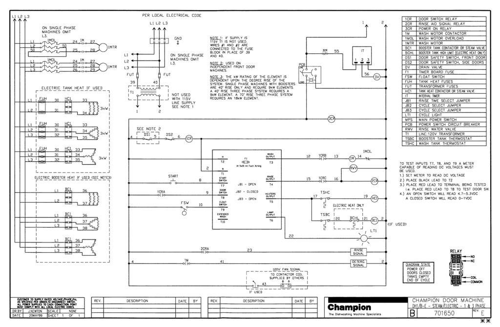
6 CONTENTS LIST OF FIGURES (cont d) Page Figure 26 D-HB, D-H1 Upper Fill Piping Assembly Figure 27 D-H1, D-LF Lower Fill Piping Assembly Figure 28 D-LF Upper Fill Piping Assembly Figure 29 Pump Assembly Figure 30 Control Cabinet Figure 31 Dishracks and PRV APPENDIXES Appendix A Conversion Information Appendix B Straight to Corner (Door Conversion Kit) Appendix C Corner to Straight (Door Conversion Kit) Appendix D Drain/Timer Circuit ELECTRIC SCHEMATICS B701650/E Wiring Diagram (D-HB, D-H1, D-LF Steam/Electric 1 & 3 Phase) iv
7 THIS PAGE INTENTIONALLY LEFT BLANK v
8 WARRANTY LIMITED WARRANTY Champion Industries Inc. (herein referred to as Champion), P.O. Box 4149, Winston-Salem, North Carolina 27115, and P.O. Box 301, 2674 North Service Road, Jordan Station, Ontario, Canada, L0R 1S0, warrants machines, and parts, as set out below. Warranty of Machines: Champion warrants all new machines of its manufacture bearing the name Champion and installed within the United States and Canada to be free from defects in material and workmanship for a period of one (1) year after the date of installation or fifteen (15) months after the date of shipment by Champion, whichever occurs first. [See below for special provisions relating to glasswashers.] The warranty registration card must be returned to Champion within ten (10) days after installation. If warranty card is not returned to Champion within such period, the warranty will expire after one year from the date of shipment. Champion will not assume any responsibility for extra costs for installation in any area where there are jurisdictional problems with local trades or unions. If a defect in workmanship or material is found to exist within the warranty period, Champion, at its election, will either repair or replace the defective machine or accept return of the machine for full credit; provided, however, as to glasswashers, Champion s obligation with respect to labor associated with any repairs shall end (a) 120 days after shipment, or (b) 90 days after installation, whichever occurs first. In the event that Champion elects to repair, the labor and work to be performed in connection with the warranty shall be done during regular working hours by a Champion authorized service technician. Defective parts become the property of Champion. Use of replacement parts not authorized by Champion will relieve Champion of all further liability in connection with its warranty. In no event will Champion s warranty obligation exceed Champion s charge for the machine. The following are not covered by Champion s warranty: a. Lighting of gas pilots or burners. b. Cleaning of gas lines. c. Replacement of fuses or resetting of overload breakers. d. Adjustment of thermostats. e. Adjustment of clutches. f. Opening or closing of utility supply valves or switching of electrical supply current. g. Cleaning of valves, strainers, screens, nozzles, or spray pipes. h. Performance of regular maintenance and cleaning as outlined in operator s guide. i. Damages resulting from water conditions, accidents, alterations, improper use, abuse, tampering, improper installation, or failure to follow maintenance and operation procedures. j. Wear on Pulper cutter blocks, pulse vanes, and auger brush. Examples of the defects not covered by warranty include, but are not limited to: (1) Damage to the exterior or interior finish as a result of the above. (2) Use with utility service other than that designated on the rating plate. (3) Improper connection to utility service. (4) Inadequate or excessive water pressure. (5) Corrosion from chemicals dispensed in excess of recommended concentrations. (6) Failure of electrical components due to connection of chemical dispensing equipment installed by others. (7) Leaks or damage resulting from such leaks caused by the installer, including those at machine table connections or by connection of chemical dispensing equipment installed by others. (8) Failure to comply with local building codes. (9) Damage caused by labor dispute. Warranty of Parts: Champion warrants all new machine parts produced or authorized by Champion to be free from defects in material and workmanship for a period of 90 days from date of invoice. If any defect in material and workmanship is found to exist within the warranty period Champion will replace the defective part without charge. DISCLAIMER OF WARRANTIES AND LIMITATIONS OF LIABILITY. CHAMPION S WARRANTY IS ONLY TO THE EXTENT REFLECTED ABOVE. CHAMPION MAKES NO OTHER WARRANTIES, EXPRESS OR IMPLIED, INCLUDING, BUT NOT LIMITED, TO ANY WARRANTY OF MERCHANTABILITY, OR FITNESS OF PURPOSE. CHAMPION SHALL NOT BE LIABLE FOR INCIDENTAL OR CONSEQUENTIAL DAMAGES. THE REMEDIES SET OUT ABOVE ARE THE EXCLUSIVE REMEDIES FOR ANY DEFECTS FOUND TO EXIST IN CHAMPION DISHWASHING MACHINES AND CHAMPION PARTS, AND ALL OTHER REMEDIES ARE EXCLUDED, INCLUDING ANY LIABILITY FOR INCIDENTALS OR CONSEQUENTIAL DAMAGES. Champion does not authorize any other person, including persons who deal in Champion dishwashing machines to change this warranty or create any other obligation in connection with Champion Dishwashing Machines. vi
9 INTRODUCTION INTRODUCTION Welcome to Champion... and thank you for allowing us to take care of your dishwashing needs. This manual covers the door-type series dishwasher models D-H1, D-HB, and D-LF. Your machine was completely assembled, inspected, and thoroughly tested at our factory before it was shipped to your installation site. This manual contains: Warranty Information Operation and Cleaning Instructions Maintenance Instructions Troubleshooting Guide Basic Service Information Replacement Parts Lists Electrical Schematics Complete and return your warranty registration card within ten (10) days after the installation of your machine. All information, illustrations and specifications contained in this manual are based upon the latest product information available at the time of publication. Champion constantly improves its products and reserves the right to make changes at any time or to change specifications or design without notice and without incurring obligation. For your protection, factory authorized parts should always be used for repairs. Replacement parts may be ordered from your Champion authorized parts distributor or from your Champion authorized service agency. When ordering parts, please supply the model number, serial number, voltage and phase of your machine, the part number, part description and quantity. 1
10 GENERAL GENERAL This manual covers the Champion door type dishwashing machine. These machines are fully automatic and come equipped with a 1-HP pump motor. The D-series dishwasher is available in the following models: Model Numbers D-H1, D-HB, D-LF The D-H1 model is a high temperature (180 F/82 C rinse) sanitizing model without booster. The D-HB model is a high temperature (180 F/82 C rinse) sanitizing model with booster. The D-LF is a low temperature (Min. 140 F/60 C) sanitizing model for use with a sodium hypochlorite (Chlorine) based sanitizer at a minimum concentration of 50PPM in the final rinse. Standard Equipment includes: D-H1, D-HB, D-LF Automatic tank fill Built-in electric (D-HB only) or steam booster heater (D-HB only) Drain Valve Electric Specified as straight-through or corner model Electric tank heat Balanced three door lift system Low-water tank heat protection 1-Hp drip-proof pump motor Door safety switches Options (D-HB only) Electric booster (70 F/39 C temperature rise) heater for 110 F/43 C supply water Steam injector or steam coil tank heat (steam booster 40 F/23 C 70 F/39 C rise) Accessories Additional dishracks: Dish rack (peg) P/N Silverware rack (flat bottom) P/N /4 Pressure reducing valve (PRV) P/N Common utility connections Two dish racks (peg and flat bottom) Detergent/chemical connection provisions Stainless steel front and side panels Top-mounted, splash-proof control console 60-second time cycle 2" O.D. gravity drain connection Water pressure regulating valve (mounted) (D-HB only) Interchangeable upper and lower spray arms 2
11 Electrical Power Requirements for Electric Heat / Electric Booster Model Voltage Booster Rise (D-HB Only) Rated Amps Minimum Supply Ckt. Conductor Ampacity Maximum Overcurrent Protective Device D-H1/LF 115/60/1 49 Amps 60 Amps 60 Amps D-H1/LF 208/60/1 25 Amps 35 Amps 35 Amps D-H1/LF 220/60/1 26 Amps 35 Amps 35 Amps D-H1/LF 230/60/1 26 Amps 35 Amps 35 Amps D-H1/LF 240/60/1 26 Amps 35 Amps 35 Amps D-H1/LF 208/60/3 14 Amps 20 Amps 20 Amps D-H1/LF 220/60/3 14 Amps 20 Amps 20 Amps D-H1/LF 230/60/3 14 Amps 20 Amps 20 Amps D-H1/LF 240/60/3 15 Amps 20 Amps 20 Amps D-H1/LF 380/60/3 9 Amps 15 Amps 15 Amps D-H1/LF 415/60/3 9 Amps 15 Amps 15 Amps D-H1/LF 480/60/3 7 Amps 15 Amps 15 Amps D-H1/LF 575/60/3 6 Amps 15 Amps 15 Amps D-HB 115/60/1 D-HB 208/60/1 40 F/23 C 69 Amps 80 Amps 80 Amps D-HB 220/60/1 40 F/23 C 76 Amps 80 Amps 80 Amps D-HB 230/60/1 40 F/23 C 76 Amps 80 Amps 80 Amps D-HB 240/60/1 40 F/23 C 76 Amps 90 Amps 90 Amps D-HB 208/60/3 40 F/23 C 39 Amps 45 Amps 45 Amps D-HB 220/60/3 40 F/23 C 39 Amps 45 Amps 45 Amps D-HB 230/60/3 40 F/23 C 43 Amps 45 Amps 45 Amps D-HB 240/60/3 40 F/23 C 43 Amps 50 Amps 50 Amps D-HB 380/60/3 40 F/23 C 24 Amps 30 Amps 30 Amps D-HB 415/60/3 40 F/23 C 25 Amps 30 Amps 30 Amps D-HB 480/60/3 40 F/23 C 18 Amps 25 Amps 25 Amps D-HB 575/60/3 40 F/23 C 15 Amps 20 Amps 20 Amps D-HB 115/60/1 D-HB 208/60/1 D-HB 220/60/1 D-HB 230/60/1 D-HB 240/60/1 D-HB 208/60/3 70 F/39 C 51 Amps 70 Amps 70 Amps D-HB 220/60/3 70 F/39 C 51 Amps 70 Amps 70 Amps D-HB 230/60/3 70 F/39 C 58 Amps 70 Amps 70 Amps D-HB 240/60/3 70 F/39 C 58 Amps 80 Amps 80 Amps D-HB 380/60/3 70 F/39 C 31 Amps 40 Amps 40 Amps D-HB 415/60/3 70 F/39 C 34 Amps 45 Amps 45 Amps D-HB 480/60/3 70 F/39 C 29 Amps 35 Amps 35 Amps D-HB 575/60/3 70 F/39 C 24 Amps 30 Amps 30 Amps Electrical Power Requirements for Steam or Gas Heat / Steam or Gas Booster Model Voltage Booster Rise (D-HB Only) Rated Amps Minimum Supply Ckt. Conductor Ampacity Maximum Overcurrent Protective Device D-H1/LF 115/60/1 22 Amps 30 Amps 30 Amps D-H1/LF 208/60/1 13 Amps 15 Amps 15 Amps D-H1/LF 220/60/1 13 Amps 15 Amps 15 Amps D-H1/LF 230/60/1 13 Amps 15 Amps 15 Amps D-H1/LF 240/60/1 11 Amps 15 Amps 15 Amps D-H1/LF 208/60/3 6 Amps 15 Amps 15 Amps D-H1/LF 220/60/3 6 Amps 15 Amps 15 Amps D-H1/LF 230/60/3 6 Amps 15 Amps 15 Amps D-H1/LF 240/60/3 6 Amps 15 Amps 15 Amps D-H1/LF 380/60/3 4 Amps 15 Amps 15 Amps D-H1/LF 415/60/3 4 Amps 15 Amps 15 Amps D-H1/LF 480/60/3 3 Amps 15 Amps 15 Amps D-H1/LF 575/60/3 3 Amps 15 Amps 15 Amps D-HB 115/60/1 D-HB 208/60/1 40 F/23 C 22 Amps 30 Amps 30 Amps D-HB 220/60/1 40 F/23 C 13 Amps 15 Amps 15 Amps D-HB 230/60/1 40 F/23 C 13 Amps 15 Amps 15 Amps D-HB 240/60/1 40 F/23 C 13 Amps 15 Amps 15 Amps D-HB 208/60/3 40 F/23 C 6 Amps 15 Amps 15 Amps D-HB 220/60/3 40 F/23 C 6 Amps 15 Amps 15 Amps D-HB 230/60/3 40 F/23 C 6 Amps 15 Amps 15 Amps D-HB 240/60/3 40 F/23 C 6 Amps 15 Amps 15 Amps D-HB 380/60/3 40 F/23 C 4 Amps 15 Amps 15 Amps D-HB 415/60/3 40 F/23 C 4 Amps 15 Amps 15 Amps D-HB 480/60/3 40 F/23 C 3 Amps 15 Amps 15 Amps D-HB 575/60/3 40 F/23 C 3 Amps 15 Amps 15 Amps D-HB 115/60/1 D-HB 208/60/1 D-HB 220/60/1 D-HB 230/60/1 D-HB 240/60/1 D-HB 208/60/3 70 F/39 C 6 Amps 15 Amps 15 Amps D-HB 220/60/3 70 F/39 C 6 Amps 15 Amps 15 Amps D-HB 230/60/3 70 F/39 C 6 Amps 15 Amps 15 Amps D-HB 240/60/3 70 F/39 C 6 Amps 15 Amps 15 Amps D-HB 380/60/3 70 F/39 C 4 Amps 15 Amps 15 Amps D-HB 415/60/3 70 F/39 C 4 Amps 15 Amps 15 Amps D-HB 480/60/3 70 F/39 C 3 Amps 15 Amps 15 Amps D-HB 575/60/3 70 F/39 C 3 Amps 15 Amps 15 Amps GENERAL 3
12 INSTALLATION INSTALLATION Unpacking! CAUTION: Care should be taken when lifting the machine to prevent damage. 1. Immediately after unpacking the machine, inspect for any shipping damage. If damage is found, save the packing material and contact the carrier immediately. 2. Remove the dishwasher from the skid. Adjust the feet if required, then move the machine to its permanent location. 3. Level the machine (if required) by placing a level on the top of machine and adjusting the feet. Level the machine front-to-back and side-to-side. 4. Remove the two dishracks and pressure gauge from the interior of the machine. Install the pressure gauge in the upper fill piping of the dishwasher in the petcock provided. NOTE: The installation of your machine must meet local health codes. Changing from Straight-through to Corner Operation Your door-type dishwasher was specified to the factory as a straight-through configuration or corner configuration. Your machine can be converted from straight-through to corner or from corner to straight-through. The factory has kits for these conversions available. For instructions and part numbers, see Appendixes A, B, and C. Electrical Connections!! WARNING: Electrical and grounding connections must comply with the National Electrical Code and/or Local Electrical Codes. WARNING: When working on the dishwasher, disconnect the electric service and place a tag at the disconnect switch to indicate work is being done on that circuit. 1. A qualified electrician must compare the electrical power supply with the machine electrical specifications stamped on the MACHINE ELECTRICAL CONNECTION PLATE located inside the top mounted control cabinet before connecting to the incoming service at a fused disconnect switch. 2. Motor rotation was set at the factory. Check the rotation of the motor shaft (CW when viewed from rear of motor). For three phase machines, reversing the motor direction is done in the control cabinet by reversing the wires L1 and L2 on the disconnect side of 4
13 INSTALLATION Electrical Connections (cont d) the main electrical connection block. For single phase machines, motor rotation is changed at the motor connection plate on the rear of the single phase motor. 3. A knock-out is provided at the rear of the top mounted control cabinet for the electrical service connection. A single source electrical connection has been provided. A fused disconnect switch or circuit breaker (supplied by others) is required to protect each power supply circuit. Plumbing Connections! CAUTION: Plumbing connections must comply with local sanitary and plumbing codes. Water Connections 1. Connect the hot water supply using a 3/4 NPT connection. The connection point is located behind the lower front panel of the dishwasher. Supply enters from underneath the machine. 8-7/8" [225 mm] 8-7/8" [225 mm] FLOOR FLOOR Figure 1 Figure 2 D-HB D-H1, D-LF 3/4 NPT Water Supply Connection 3/4 NPT Water Supply Connection Behind Front Panel Behind Front Panel 2. Minimum incoming water supply temperature requirements are listed below: D-HB with built-in 40 F/23 C rise electric booster (Minimum 140 F/60 C) (Min./Max. flow pressure psi/138 Kpa) D-HB with built-in 70 F/39 C rise electric booster (Minimum 110 F/43 C) (Min./Max. flow pressure psi/138 Kpa) D-H1 without built-in booster (Minimum 180 F/70 C) (Min./Max. flow pressure psi/138 Kpa) D-LF (Minimum 140 F/60 C) (Min./Max. flow pressure psi/138 Kpa) 5
14 INSTALLATION Water Connections (cont d) 3. A manual shut-off valve for steam and water (supplied by others) should be installed in supply line to allow for servicing of the machine. The shut-off valve should be the same size or larger than the supply line. 4. A 3/4" Pressure Regulating Valve (PRV), should be installed on the incoming water supply line if water flow pressure exceeds psi/138 Kpa. A PRV is standard equipment on Model D-HB. A PRV is not standard equipment on Models D-H1 and D-LF. The PRV may be obtained locally or direct from Champion. Drain Connections 1. Models D-HB, D-H1, and D-LF are GRAVITY DRAIN machines equipped with a 2" hose connection point. Drain height for ALL MODELS must not exceed 8-7/8" [225 mm] above floor level.! WARNING: Connection of the machine to a drain line higher than the machine drain height will prevent the machine from draining properly. Ventilation NOTE: Ventilation must comply with local sanitary and plumbing codes.! CAUTION: Exhaust air should not be vented into a wall, ceiling, or concealed space of a building. Condensation can cause damage. 6
15 INSTALLATION Chemical Connections NOTE: Consult a qualified chemical supplier for your chemical needs. Models D-HB, D-H1 and D-LF Refer to Figure Labeled chemical signal connection points are provided inside the control cabinet for chemical dispensing equipment (supplied by others). 5 6 CAUTION 120V SUPPLY DISPENSERS ONLY RINSE/SANI COMMON RETURN DETERGENT Signal connection points include: Detergent signal 120VAC between Wire #10 and Wire #2 (1 AMP MAX AMP LOAD) Rinse Aid/Sanitizer signal 120VAC between Wire #15 and Wire #2 (1 AMP MAX AMP LOAD) Figure 3 D-HB, D-H1, D-LF Chemical Connection Points Left Side Interior of Control Cabinet Detergent Refer to Figure Two removable black plugs, located on the rear and left side of the wash tank are provided as detergent equipment insertion points. 1/2" Black Removable Plug Detergent Injection Point 1/2" Black Removable Plug Detergent Sensor Point Figure 4 D-HB, D-H1, D-LF Wash Tank Detergent Equipment Insertion Points 7
16 INSTALLATION Chemical Connections (cont d) Detergent (cont d) 2. Detergent may be added manually if dishwasher is not equipped with dispensing equipment. Consult your chemical supplier for recommended amounts. Rinse Aid/Sanitizer Model D-HB and D-H1 Refer to Figure A rinse aid injection point is provided via a 1/4" NPT plug located in the final rinse piping. The plug is located in a cross fitting on the outlet side of the vacuum breaker. The vacuum breaker is located behind the control cabinet at the top of the machine. 2. Use a liquid rinse aid. Figure 5 Rinse Aid Injection Point D-HB, D-H1 Only NOTE: Models D-HB and D-H1 do not require sanitizer. 8
17 INSTALLATION Chemical Connections (cont d) Rinse Aid/Sanitizer (cont d) Model D-LF Refer to Figure A rinse aid injection point is provided via a 1/4" NPT plug located in the final rinse piping. The plug is located in a cross fitting on the outlet side of the vacuum breaker. The vacuum breaker is located behind the control cabinet at the top of the machine. 2. Use a liquid rinse aid. 3. A sanitizer injection point is provided via a 1/8" NPT plug located in the final rinse piping. The plug is located in a cross fitting on the outlet side of the vacuum breaker. The vacuum breaker is located behind the control cabinet at the top of the machine. 4. Use a sodium hypochlorite (Chlorine) based sanitizer at a minimum concentration of 50PPM in the final rinse. Use chlorine test papers to verify and monitor the 50PPM chlorine level.! Figure 6 D-LF Rinse Aid/Sanitizer Injection Points WARNING: Never premix rinse aid with the sanitizing agent. Mixing may cause hazardous gases to form.! CAUTION: Some metal, including silver, aluminum, and pewter are attacked by sodium hypochlorite (chlorine sanitizer). Avoid cleaning these metals in a D-LF dishwasher. 9
18 INITIAL START-UP INITIAL START-UP After plumbing and electrical connections are completed, follow the steps below to place your machine in service. Model D-HB, D-H1 and D-LF Refer to Figures 7 and 8 below. 1. Remove any foreign material from inside the machine. Make sure scrap screens are in place. 2. Make sure wash and rinse arms are installed correctly. 3. Close the Door. 4. Turn the water and main power sources to the dishwasher ON. 5. Flip the Power switch to the ON position. The power on light will illuminate and the machine will automatically fill with water. 6. Check the machine for leaks. 7. Push the Green Start Button to check automatic cycle. 8. Check pump motor rotation. Rotation is CW when viewed from rear of motor. 9. If machine checks okay, flip the power switch to OFF and machine will drain for ten minutes. Main power switch circuit breaker Pressure gauge POWER START Green pushbutton start switch IN CYCLE Champion WASH RINSE ON OFF WARNING! TURN OFF POWER BEFORE SERVICING MACHINE Green in cycle lite Temperature Gauges Figure 7 Operator Controls Top Mounted Control Cabinet POWER ON OFF Figure 8 Drain Assembly 10
19 OPERATION OPERATION Model D-HB, D-H1 and D-LF 1. Close the door and flip power switch ON Power light illuminates. Drain valve closes. Tank fills automatically and tank heat comes on. 2. Monitor wash tank temperature gauge Wait for temperature reading to reach Min. 150 F/66 C (D-HB, D-H1 Only) Temperature reading must be Min. 120 F-140 F/49 C-60 C Optimum (For D-LF Only) 3. Prescrap and load ware into rack Place dishes edgewise in peg rack, cups and bowls upside down in flat rack, and silverware spread evenly in single layer in flat rack. 4. Open door, insert rack 5. Close door, Push Green start button Green cycle light will illuminate. Automatic cycle begins. Machine washes for 45 sec., then pauses for 1 sec. 6. During Final Rinse monitor pressure Machine final rinses for 14 sec. Pressure gauge and final rinse temperature gauge reading must read between PSI. Temperature gauge must read F/82 91 C (D-HB, D-H1 Only) Min F/49 C 60 C Optimum (D-LF Only) second cycle complete Green cycle light goes out. 8. Open door, remove clean rack Insert another rack of soiled ware. 9. After each meal period or every two Turn power switch to OFF position and hours operation machine will drain for ten minutes. Flush interior and clean scrap screens and pump intake strainer. Check spray arms and clean if necessary. Flip power switch ON and OFF to drain remaining water repeat as necessary. NOTE: Opening the door at any time during the cycle will stop the machine. Closing the door and pushing the Green start button will resume the cycle where it left off. 11
20 MAINTENANCE MAINTENANCE Cleaning your machine is the best maintenance that you can provide. Components that are not regularly flushed and cleaned do not perform well. The Maintenance intervals shown in the following schedules are the minimum requirements necessary for the proper performance of your machine. Maintenance intervals should be shortened whenever your machine is faced with abnormal working conditions, hard water, or multiple shift operations. Maintenance Schedule CLEANING Every 2 Hours or After Each Meal Period Model D-HB, D-H1, and D-LF 1. Flip the power switch OFF. 2. Machine drain valve will open for 10 minutes automatically. 3. Flush tank interior with fresh water. 4. Remove and clean the scrap screens. Clean the pump intake screen. 5. Inspect the spray arm nozzles and rinse nozzles. Clean if necessary. 6. Close door, flip power switch ON to refill machine. Every 8 Hours or at the End of the Day Model D-HB, D-H1, and D-LF 1. Flip the power switch OFF. 2. Machine drain valve will open for 10 minutes automatically. 3. Flush tank interior with fresh water. 4. Remove and clean the scrap screens. Clean the pump intake screen. 5. Remove the spray arms. 6. Clean and inspect the spray arm bearings. 7. Flush the wash arm and rinse arm assemblies and nozzles. 8. Back flush the scrap screens and pump intake strainer. 9. Flip power switch ON then OFF to open drain valve for 10 minutes. 10. Reassemble the machine. Leave the door open to aid overnight drying.! CAUTION: DO NOT LEAVE WATER IN WASH TANK OVERNIGHT 12
21 MAINTENANCE DELIMING Your dishwasher should be delimed regularly depending on the mineral content of your water. Inspect the machine interior for mineral deposits and use a deliming solution for the best cleaning results. NOTE: Consult your chemical supplier for an appropriate deliming solution.! WARNING: Deliming solutions or other acids must not come in contact with household bleach (sodium hypochlorite) or any chemicals containing chlorine, iodine, bromine, or fluorine. Mixing will cause hazardous gases to form. Skin contact with deliming solutions can cause severe irritation and possible chemical burns. Consult your chemical supplier for specific safety precautions. DELIMING PROCESS Model D-HB, D-H1, and D-LF 1. Remove all dishes from machine. 2. Remove any chemical pick-up tubes from their containers. 3. Place each tube in a container of fresh water and prime the chemical lines for several minutes to thoroughly flush chemical from the lines. Leave pick-up tubes out of their containers. 4. Turn power switch to OFF position to drain machine for ten minutes, return power switch to ON position to refill with fresh water. 5. Spray interior walls with delimimg solution and let sit for 5 or 10 minutes depending on amount of build-up. Add deliming solution to wash tank. Do not let chemicals sit for longer than 15 minutes. 6. Push the Green start button and run an automatic cycle. 7. Repeat Steps 3-4 if necessary. 8. Repeat Step Refill the machine and run a complete cycle two additional times. Drain and refill the machine after each cycle to thoroughly flush any deliming solution from the interior of the machine. 10. Flip the power switch to OFF. 11. Machine drain valve will open for 10 minutes to drain machine completely. 12. Deliming is complete. 13
22 MAINTENANCE OPERATION CHECKS Daily 1. Check temperature gauges for proper readings. 2. Check pressure gauge for proper reading (D-H1, D-HB ONLY). 3. Check for leaks. 4. Check chemical supplies and refill as necessary. Weekly 1. Inspect all water lines for leaks. 2. Clean all detergent residue from the exterior of the machine. 3. Check the drains for leaks. 4. Clean accumulated mineral deposits from the tank heating elements 5. Check that float switch moves freely. TROUBLESHOOTING Before determining any specific cause of a breakdown or abnormal operation on your dishwasher, check that: Checklist 1. Main power and water supply are turned on to the machine 2. All switches are ON 3. Wash pipe and rinse nozzles are clean 4. Scrap screen(s) are properly positioned 5. Spray pipes are in their proper positions 6. Doors are fully closed 7. Thermostat(s) are at their correct setting 8. Sanitizer, detergent, and rinse additive dispensers are adequately filled. 9. Drain valve/timer problems see Appendix D for trouble shooting. If a problem still exists, use the following for troubleshooting. 14
23 TROUBLESHOOTING CONDITION CAUSE SOLUTION Machine will not start Door not closed Make sure doors are fully closed Door safety switch faulty Contact your service agency Start switch faulty Contact your service agency Main switch OFF Check disconnect Overload protector tripped Reset overload in control box Low or no water Main water supply is turned off..... Turn on house water supply Faulty drain valve Contact your service agency Machine doors not fully closed..... Close doors securely Faulty fill valve Contact your service agency Defective circuit board Contact your service agency Stuck or defective float Check floats and clean Clogged Y strainer Clean or replace Continuous water filling Stuck or defective float Check floats and clean Drain valve will not close Replace drain valve/contact your service agency Fill valve will not close Clean or replace Defective circuit board Contact your service agency Any motor not running Overload protector tripped Reset overload in control box Defective motor Contact your service agency Wash tank water Incoming water temperature temperature is low at machine too low Raise temperature to: when in use F/60 C for D-HB and D-LF, F/82 C for D-H1 Defective thermometer Check or replace Defective thermostat Check for proper setting or replace Lime scale buildup on heating elements Delime element Defective heater element Check or replace Low steam pressure Check steam supply pressure (15 30 psi) Defective steam trap Check or replace Defective solenoid valve Check or replace Insufficient pumped Clogged pump intake screen Clean spray pressure Clogged spray pipe Clean Scrap screen full Must be kept clean and in place Low water level in tank Check drain Pump motor rotation incorrect Reverse connection between L1 and L in Control Cabinet (3PH machines only) Defective pump seal Contact Service Agent Insufficient final rinse or Faulty pressure reducing valve..... Clean or replace no final rinse Improper setting on pressure reducing valve Set psi flow pressure at psi/138 Kpa Clogged rinse nozzle and/or pipe.... Clean Improper water line size Have installer change to proper size (3/4" min.) Clogged Y strainer Clean or replace Low final rinse temperature Low incoming water temperature... Check house supply water temperature Improper setting of booster thermostat Be sure booster thermostat is set to maintain F/82 C temperature Defective booster thermostat Replace thermostat Defective thermometer Check for proper setting or replace Poor washing results Detergent dispenser not operating properly Contact detergent supplier Insufficient detergents Contact detergent supplier Wash water temperature too low See condition Wash tank water temperature above. Wash arm clogged Clean Improperly scraped dishes Check scraping procedures Ware being improperly placed in rack Use proper racks. Do not overload racks Improperly cleaned equipment Unclog wash sprays and rinse nozzles to maintain proper pressure and flow conditions Keep wash water as clean as possible. Electric Elements or steam coils has soil/lime buildup Clean and/or delime Poor drying results Insufficient rinse-aid Contact chemical supplier Low final rinse temp See condition Low final rinse temperature above. 15
24 BASIC SERVICE BASIC SERVICE This Basic Service section does not cover all possible repair procedures. If you require additional service support, you may call your local service company or: Champion National Service In Canada Please have the Model and Serial Number of the machine ready when you call. ELECTRICAL SERVICE! WARNING: Disconnect Power at main disconnect switch before removing lower panels. Removing lower panels exposes live open electrical wiring (not contained in conduit). Always replace panels after completing service or repairs. Do not operate the dishwasher with panels removed for anything other than service repair operation. NOTE: DO NOT USE CHASSIS GROUND WHEN PERFORMING VOLTAGE CHECKS. Doing so will result in false and inaccurate readings. PERFORM VOLTAGE CHECKS BY READING FROM THE HOT SIDE OF THE LINE AND NEUTRAL (any #2 or white wire).!! WARNING: USE EXTREME CAUTION when performing tests on energized circuits. WARNING: When repairing a circuit, disconnect the power at the main service disconnect switch and place a tag at the disconnect switch to indicate that work is being performed on the circuit. Troubleshooting Schematics Champion places an electrical schematic in the control cabinet of every machine before it is shipped. Schematics are included at the back of this manual as well. Be aware that these schematics include options that may not apply to your machine. Options are enclosed in dashed lines with the words (IF USED) next to them on the schematic. Disregard any options that appear on the schematics which are not a part of your machine. 16
 fuses protect the wash tank heater circuit. Fuses are marked FU on the electrical schematic. Booster heater circuits (D-HB only) are not fused.")

25 BASIC SERVICE Fuses Refer to Figure 9. There are two fuse blocks, located in the center of the main control cabinet. The (A) fuses protect the main control transformer. The (B) fuses protect the wash tank heater circuit. Fuses are marked FU on the electrical schematic. Booster heater circuits (D-HB only) are not fused. To Replace a fuse: Turn the dishwasher main power switch off. Disconnect power to the machine at the main service disconnect switch. Replace the fuse. If the fuse blows again, DO NOT INCREASE THE FUSE SIZE. DETERMINE THE CAUSE OF THE OVERLOAD. A Figure 9 Fuses (Three phase shown) B Motor Overloads The wash pump motor has an overload to protect it from line voltage electrical overloads. The overload disconnects 120VAC power to the motor contactor coil. Refer to Figure 10. Note the Switch Lever on the Overload. If the switch lever is off with the 0 showing then the overload has tripped. To Reset the Motor Overload: Switch Lever Flip the overload switch to the On position. A 1 should be visible on the switch lever. To Replace a Motor Overload: Disconnect the wires to the overload. Release the mounting catch on the front side of the overload. Push forward and lift out. Snap the new overload into place and reconnect the wires. To adjust the overload setting: The screwdriver in Figure 10 is positioned to adjust the motor overload AMP setting. Read the full load amps (FLA) motor amps on the motor nameplate. Turn setting to match nameplate. Solid State D-HB, D-H1, and D-LF Operating Instructions Automatic Operation 1. Check that drain is closed and screens are in place. 2. Turn on main power to the machine. 3. Flip machine control panel power switch to ON. 4. Close doors.* *Machine pauses 4 seconds to check water level. 5. Machine fills for 110 seconds if float is down. Figure 10 Motor Overload 17
26 BASIC SERVICE ELECTRICAL SERVICE (cont d) 6. Run machine through several cycles or wait 10 minutes for temperature to stabilize. 7. Open door, insert rack of dishes. 8. Close doors. Push the GREEN push button to start cycle. 9. Machine cycle is: WASH = 45 seconds DWELL = 1 second RINSE = 14 seconds 10. Open door, remove clean rack of dishes. 11. Repeat for additional racks. Troubleshooting Timer Circuit Board 1.1 Introduction The following procedures are for determining whether or not the timer circuit board itself is faulty. In this part Checking the general condition of the circuit board. Testing inputs. Testing outputs. Special Tools A voltmeter capable of reading DC and AC volts. 1.2 Checking General Condition Before testing the inputs and outputs, you should first check that the board is receiving power. Turn on the power switch to the unit (do not start the unit, just turn ON power to the unit). If red POWER LED on board is illuminated, go directly to 1.3 Testing Board Inputs. When LED is not illuminated, then check that the following conditions are true: Power Terminals Verify that the board is receiving power of 120 VAC at the terminals: T2, marked H (AC Hot). T1, marked N (AC Neutral). If either of these terminals is not receiving 120 VAC, then there is a problem elsewhere with the unit not receiving power. The Fuse (F1) Verify that the circuit board fuse (F1) is good. If not replace it. Red POWER LED Verify that the red POWER LED is illuminated. If it is not, and the previous two conditions are true, then the board is bad and should be replaced. 1.3 Testing Board Inputs After you have verified that the circuit board is receiving power (as explained above), then test the board inputs. There are 4 board inputs: Start Switch Door Safety Switch Float Switch Extended Wash (not used on this Model) Perform the following steps to test a board input: 1. Set the voltmeter to measure DC volts. 18
27 BASIC SERVICE 2. Place the NEGATIVE (Black) test probe on the HOT terminal: T2, marked H. 3. Place the POSITIVE (Red) test probe on the input terminal to be tested: T7, marked START SW (for the Start Switch). T8, marked DOOR SW (for the Door Safety Switch). T9, marked FLOAT SW (for the Float Switch). 4. Check the results on the voltmeter: If switch is opened the meter should read between 4.7 to 5.3 DC volts. If switch is closed the meter should read between 0 to 1 DC volts. 1.4 Testing Board Outputs After you have verified that the circuit board is receiving power (as explained above), then test the board outputs. There are 4 board outputs: Wash Cycle Rinse Cycle Heaters In-Cycle Lamp Perform the following steps to test a board output: 1. Set the voltmeter to measure AC volts. 2. Place the NEGATIVE (Black) test probe on the NEUTRAL terminal: T1, marked N. 3. Place the POSITIVE (Red) test probe on the output terminal to be tested: T3, marked WASH OUTPUT (for the Wash Cycle). T4, marked RINSE OUTPUT (for the Rinse Cycle). T5, marked HEATERS OUTPUT (for the Water Heater). T6, marked LAMP OUTPUT (for the In-Cycle Lamp indicator). 4. Check the results on the voltmeter for the terminal you are testing: For T3 the meter should read 120 VAC whenever the unit is in cycle and the WASH LED is illuminated on the circuit board. For T4 the meter should read 120 VAC whenever the unit is in a fill or rinse mode and the corresponding FILL or RINSE LED is illuminated on the circuit board. For T5 the meter should read 120 VAC whenever the power switch is on and the wash tank is full (i.e., the float switch is up). For T6 the meter should read 120 VAC whenever the machine is in cycle. F1 H T2 N WASH OUTPUT T3 T1 START SW. POWER RINSE OUTPUT T7 L1 T4 DOOR SW. T8 FLOAT SW. T9 EXT. WASH T10 L2 L3 U1 L4 JB3 JB1 HEATERS OUTPUT T5 LAMP OUTPUT T6 FILL RINSE WASH JB2 Figure 11 Solid State Control Board 19

28 BASIC SERVICE Models D-HB, D-H1, and D-LF use a float switch and circuit board to control tank fill and tank heat. For Model D-HB only, the built-in booster heat circuit is also controlled by the float switch. Operation: 1. When dishwasher main power switch is turned on (wash tank empty), the drain valve closes allowing cycle time to run for a minimum of 110 seconds to fill the tank. 2. The float switch ball rises; its normally open contacts close. The fill circuit times out; the fill solenoid de-energizes, and the tank heat and booster heat energize. 3. If water level drops below the float level, the float switch ball moves down; heat de-energizes. The fill solenoid energizes and the fill cycle runs for a minimum of 110 seconds to refill the tank. Figure 12 Float Switch 4. If the tank is not full of water at the end of the 110-second fill cycle, then the machine will cycle again. When the float switch is satisfied, the fill cycle stops after completing its 110-second cycle. 5. Refer to the float switch troubleshooting chart (Fig.13) below, for a quick guide to evaluating float switch problems. Wash Tank Fills Constantly Is Tank Full of Water? YES NO Check Drain Is the Float Ball Up? YES NO Clean Float Assy Is Heat ON when called for? YES NO Replace Float Check Solenoid Valve System Checks Figure 13 Float Switch Troubleshooting Chart 20
29 BASIC SERVICE Heater Element Wiring Booster Tank and Wash Tank Heater Elements Refer to the illustrations and follow the steps below to properly install terminal jumpers and to make line power connections to a replacement element. Step 1. Hold the element assembly with the calrod coils facing toward you. Step 2. Match your element coil to Configuration A, B, C, or D. Step 3. Rotate your element coils to match the correct configuration. Step 4. Turn the element over and match your element to the correct terminal configuration. Step 5. Install terminal jumpers according to the illustration for your voltage requirement. Step 6. Install the element and make your line connections 1L1, 1L2, or 1L3 per the illustration. Configuration A Booster tank element View of calrod coils Terminal Connections view of element 1L1 1L3 1L3 1L3 1L1 1L2 1L1 1L1 1L2 1L2 1L2 208V/1 Phase V/3 Phase Delta Connection 480V/3 Phase 575V/3 Phase Delta Connection V/3 Phase Wye Connection for V/3 Phase Configuration B Booster tank element View of calrod coils 1L1 1L1 Terminal Connections view of element 1L1 1L2 1L2 1L2 1L3 1L3 1L1 1L2 1L3 Configuration C Booster tank element View of calrod coils 208V/1 Phase V/3 Phase Delta Connection 1L1 480V/3 Phase 575V/3 Phase Delta Connection V/3 Phase Wye Connection for V/3 Phase Terminal Connections view of element 1L2 1L1 1L1 1L3 1L1 1L3 1L3 1L2 1L2 1L2 Configuration D Wash tank element View of calrod coils 208V/1 Phase V/3 Phase Delta Connection 1L1 1L1 480V/3 Phase 575V/3 Phase Delta Connection V/3 Phase Wye Connection for V/3 Phase Terminal Connections view of element 1L1 1L1 1L2 1L2 1L3 1L2 1L3 1L2 1L3 208V/1 Phase V/3 Phase Delta Connection 480V/3 Phase 575V/3 Phase Delta Connection V/3 Phase Wye Connection for V/3 Phase 21
30 BASIC SERVICE Motor Connections 1. Models D-HB, D-H1, and D-LF are available in either single phase or 3 phase voltages. 2. Motor rotation was set at the factory. For three phase machines, reversing the motor direction is done in the control cabinet by reversing the wires L1 and L2 on the disconnect side of the main electrical connection block. For single phase machines, motor rotation is changed at the motor connection plate on the rear of the single phase motor (if necessary). Refer to Figure 14 for the proper wiring of the pump motor for single and three phase voltages. Single Phase - Low Voltage Single Phase - High Voltage L1 3 4 J 8 LINE 115V L1 3 4 LINE J V L2 2 LINE Figure 14 Pump Motor Wiring Diagrams L2 LINE V 480V Three Phase - Low Voltage Three Phase - High Voltage 575V Only Three Phase LINE LINE LINE 22
31 REPLACEMENT PARTS MECHANICAL SERVICE Pump Seal Replacement 1. Disconnect the power to the machine at the main breaker panel or fuse box. 2. Drain the machine. 3. Remove the front and side panels. 4. Remove drain plug on the pump volute and drain the pump. 5. Remove the pump hoses. 6. Disconnect the wires to the motor at the motor junction box. 7. Unbolt motor from machine base and remove the pump/motor assembly. 8. Remove bolts on volute and carefully remove from the pump flange. 9. Lock the motor shaft with a wrench or pliers. The back of motor shaft is square. 10. Turn the impeller counter-clockwise to remove from shaft (right hand threads). 11. Remove the old seal and discard. 12. Check seal seat in the pump flange and clean thoroughly. 13. Press rubber seal/ceramic portion of seal assembly into the pump flange. Use a water soluble lubricant. Be careful to keep the ceramic clean. 14. Install the rotating part of the seal on the shaft with the graphite surface toward the ceramic. Use a water soluble lubricant on the rubber seal part only (not the graphite). 15. Reinstall impeller and new flange gasket. Reinstall bolts. 16. Reinstall the pump/motor assembly and reconnect the pump hoses. 17. Fill the dishwasher with water. 18. Check motor rotation by bump starting motor. Correct motor shaft rotation is clockwise when viewing motor from the rear. 19. Test run and check for leaks. Pump Flange Impeller Gaskets Volute Seal Assy. Washer Bolt (B) Water Slinger Nut Backing Plate Mtg. Nut Backing Plate Bolt (A) Plug Figure 15 Pump Seal Replacement 23
32 24 THIS PAGE INTENTIONALLY LEFT BLANK
33 REPLACEMENT PARTS REPLACEMENT PARTS 25
34 REPLACEMENT PARTS Figure 16 D-HB/D-H1/D-LF Doors, Panels and Gauges 26
35 REPLACEMENT PARTS D-HB/D-H1/D-LF DOORS, PANELS AND GAUGES Fig. 16 Part Item No. No. Part Description Qty Side Door, Right Side Door, Right (Corner Machine) Front Door RH Panel, No Cut Out Screw 1/4-20 x 5/8 Truss Head Panel Front LH Panel w/cut Out Plug, Plastic Washer 13/16 x 1-13/ Nut, Plastic Door, Side Left Magnet Assembly Nut, Grip 6/32 w/nylon Insert Screw x 3/8 Truss Head Screw 4-40 x 5/8 Round Head Decal Control Cabinet Thermometer 4-ft. Gas Filled (Final Rinse) (Replaces ) Overlay, Final Rinse F Overlay, Final Rinse 120 F (D-LF Only) Thermometer 8-ft. (Wash) Overlay, Wash 150 F Overlay, Wash 120 F (D-LF Only) Control Cabinet Cover Chain, Bead # Chain, End Coupling Gauge, Pressure (0 60 PSI) Overlay, Pressure Gauge Foot, Cast Grey Screw 8-32 x 1/2 Pan Head Splash Baffle (Front & Side Doors) (Not Shown) A/R Splash Baffle (Top of Hood) (Not Shown) A/R Splash Baffle (Side, Top of Hood) (Not Shown) A/R Splash Baffle (Front, Side, Top of Hood) (Not Shown) A/R 27
36 REPLACEMENT PARTS Fig. 17 D-HB/D-H1/D-LF Door Guides, Stops, and Lift Bracket 28
37 REPLACEMENT PARTS D-HB/D-H1/D-LF DOOR GUIDES, STOPS, AND LIFT BRACKET Fig. 17 Part Item No. No. Part Description Qty Plug, Cornerpost Nut, Grip w/insert Bracket, Door Lift Screw x 1/2" Truss Head Guide, Door Gasket, Door Guide (26") Screw 8-32 x 1 Filister Screw x 3/8 Truss Head Stop, Door
38 REPLACEMENT PARTS Fig. 18 D-HB/D-H1/D-LF Door Handle and Spring Assembly 30
39 REPLACEMENT PARTS D-HB/D-H1/D-LF DOOR HANDLE AND SPRING ASSEMBLY Fig. 18 Part Item No. No. Part Description Qty Bolt 5/15-18 x 11 Hex Head Spring, Extension Block, Spring Hook Door Handle (Straight Thru Machine) Door Handle (Corner Machine) Bolt M6 x 45mm Hex Head Block, Upper Pivot Pin, Pivot Handle, Grip Block, Lower Pivot Nut, Plain M Screw M6 x 16mm Filister Support, Pivot Block Gasket, Backing Plate, Backing Bolt 5/16-18 x 1" Hex Head Nut, Grip w/nylon Insert Guard, Splash Screw, x 1/2 Truss Head Bushing, Side Door T Nut, Toplock 5/16-18 SST Lift Bar, Door Washer, Flat Bolt x 1-1/ Nut, Plain 5/ Washer, Lock 5/16 Split Washer 5/16 x 3/4 x 1/ Spring Anchor Bracket
40 REPLACEMENT PARTS Fig. 19A D-HB/D-H1/D-LF Straight Track Assembly Fig. 19B D-HB/D-H1/D-LF Corner Track Assembly 32
41 REPLACEMENT PARTS D-HB/D-H1/D-LF STRAIGHT TRACK ASSEMBLY Fig. 19A Part Item No. No. Part Description Qty Track, Rear Screw (1/4-20 x 1/2 Truss Head) Washer, Lock Nut (1/4-20 Hex Head) D-HB/D-H1/D-LF CORNER TRACK ASSEMBLY Fig. 19B Part Item No. No. Part Description Qty Guide, Right Hand Track, Rear Guide, Left Hand Support, Rack Track, Front Screw (10-32 x 5/8 Flat Head) Nut, Grip (10-32 w/nylon Insert) Screw (1/4-20 x 1/2 Truss Head) Washer, Lock Nut (1/4-20 Hex Head) Spacer
42 REPLACEMENT PARTS FRONT LEFT SIDE Fig. 20 D-HB/D-H1/D-LF Wash/Rinse Spray Piping 34
43 REPLACEMENT PARTS D-HB/D-H1/D-LF WASH/RINSE SPRAY PIPING Fig. 20 Part Item No. No. Part Description Qty Rinse Manifold Weldment Connector, Rinse Arm Top Rinse Arm Connector Spindle, Wash Arm Support, Wash Arm Standpipe, Wash Bolt 1/4-20 x 3/4 Hex Head Nut, Grip 1/ Gasket, Standpipe Wash Bolt 5/16-18 x 1" Hex Head Washer, Lock 5/16 Split Washer, Flat Nut, Plain 5/
44 REPLACEMENT PARTS Fig. 21 D-HB/D-H1/D-LF Wash/Rinse Spray Arms 36
45 REPLACEMENT PARTS D-HB/D-H1/D-LF WASH/RINSE SPRAY ARMS Fig. 21 Part Item No. No. Part Description Qty Spindle, Rinse Arm Nozzle, Rinse Arm (DHB, D-H1 Only) Bearing, Rinse Arm Rinse Arm Assembly (Includes 2 & 3) Nut, Rinse Arm Screw (#8 x 1/2 Pan Head) S Wash Arm Assembly (Includes 6 & 8) Bearing, Wash Arm Nozzle Rinse Arm (SST) (Model D-LF Only) Rinse Arm Assembly (Model D-LF Only) (Includes 3 & 9) Rinse Arm (Does Not Include Items 2, 3, or 9) Wash Arm (Does Not Include Item 8)
46 REPLACEMENT PARTS Fig. 22 D-HB/D-H1/D-LF Drain Assembly and Scrap Screens 38
47 REPLACEMENT PARTS D-HB/D-H1/D-LF DRAIN ASSEMBLY AND SCRAP SCREENS Fig. 22 Part Item No. No. Part Description Qty Screen 10" Filler Plate Bolt 1/4-20 x 3/4 Hex Head Washer, Flat Grip, Nut 1/4-20 w/nylon Insert Strainer Connector, Electric Drain Valve Clamp, Hose Hose, Rubber Electric Drain Valve (After S/N D2964) Kit, Drain Valve (From S/N D2099 thru D2963) Hose Clamp Overflow Hose Overflow Flange Weldment Gasket, Drain Flange Washer, Lock 1/4 Split Nut, Plain 1/4-20 SST
48 REPLACEMENT PARTS Thermostat bracket detail Fig. 23 D-HB/D-H1/D-LF Wash Tank Heat, Thermostats, and Float Switch 40
49 REPLACEMENT PARTS D-HB/D-H1/D-LF WASH TANK HEAT, THERMOSTATS, AND FLOAT SWITCH Fig. 23 Part Item No. No. Part Description Qty Thermometer 8 ft Thermostat w/cap F Washer Nut, Lock 1/2" Dual Thermostat Bracket Nut, Jam 1/ Washer Float Switch C-clip Float Switch Bolt 5/16-18 x 1 Hex Head Gasket 3 x 3 x 1/8 2" Washer 5/16 x 3/4 x 1/ Washer, Lock 5/16 Split Nut, Plain 5/16-18 SST Heater 3kw 115v/1ph Heater 3kw / v 1/3ph Heater 3kw 480v/3ph Heater 3kw 575v/3ph Screw x 3/8 Truss Head Nut, Grip w/nylon Insert Washer, Lock 1/4 Split Plain Nut 1/4-20 SST Putty, Sealing (Use To Seal Items 1, 2 & 8) A/R 41
50 REPLACEMENT PARTS 5 FROM FILL VALVE TO UPPER PIPING Fig. 24 D-HB Only Electric Booster and Thermostat 42
51 REPLACEMENT PARTS D-HB ONLY ELECTRIC BOOSTER AND THERMOSTAT Fig. 24 Part Item No. No. Part Description Qty Bolt 5/16-18 x 1 Hex Head Washer, Flat 5/16 x 3/4 x 1/ Nut, Grip 6-32 w/insert Thermostat, High Limit Compound, Heat Sink A/R Thermostat, Booster Nut, Plain 1/4-20 SST Washer, Lock 1/4 Split Heater 9kw / v, 40 Rise (1 & 3 Phase) Heater 9kw 480v, 40 Rise (3 Phase Only) Heater 9kw 575v, 40 Rise (3 Phase Only) Heater 18kw / v, 70 Rise (1 & 3 Phase) Heater 18kw 480v, 70 Rise (3 Phase Only) Heater 18kw 575v, 70 Rise (3 Phase Only) Seal, Electric Heater Plug 1/8 SST Tank, Booster
52 REPLACEMENT PARTS TO UPPER PIPING CUSTOMER WATER INLET Fig. 25 D-HB ONLY Lower Fill Piping Assembly 44
53 REPLACEMENT PARTS D-HB ONLY LOWER FILL PIPING ASSEMBLY Fig. 25 Part Item No. No. Part Description Qty Line Strainer/PRV Combo Street Ell 3/4" NPT Brass Nipple 3/4" x 2" Brass Valve 3/4" NPT Hot Water Nipple 3/4" NPT Elbow 3/4" NPT x Union 3/4" NPT Brass Compression Fitting 3/4" x 7/8" /4" Copper Tube (Formed) Coil, Solenoid Valve (120v) Repair Kit, 3/4" Solenoid Valve
54 REPLACEMENT PARTS WATER IN FROM LOWER PIPING FINAL RINSE THERMOMETER BULB Fig. 26 D-HB/D-H1 Upper Fill Piping Assembly 46
55 REPLACEMENT PARTS D-HB/D-H1 UPPER FILL PIPING ASSEMBLY Fig. 26 Part Item No. No. Part Description Qty Locknut 3/4" NPT Brass Union, 3/4" NPT Brass Nipple, Close 3/4" NPT Brass Plug 1/4" NPT Plastic Bushing, Reducing 3/4 x 1/4 NPT Plastic Cross, 3/4 NPT Brass Nipple 3/4 x 2-1/2 NPT Brass Tee 3/4 x 1/2 x 3/4 NPT Brass Bushing, Reducing 1/2 x 1/4 NPT Brass Needle Valve 1/4" Gauge, Pressure (0-60 PSI) Vacuum Breaker 3/4" (Prior to S/N D3290) Vacuum Breaker 3/4" (After S/N D3291) Repair Kit 3/4" Vacuum Breaker (Not Shown) (Prior to S/N D3290) Repair Kit 3/4" Vacuum Breaker (Not Shown) (After S/N D3291) Compression Fitting 3/4 NPT x 7/8" OD Bushing, Reducing 3/4 x 1/2 NPT Brass
56 REPLACEMENT PARTS 9 TO UPPER PIPING CUSTOMER WATER IN Fig. 27 D-H1/D-LF Lower Fill Piping Assembly 48
57 REPLACEMENT PARTS D-H1/D-LF LOWER FILL PIPING ASSEMBLY Fig. 27 Part Item No. No. Part Description Qty Street Ell 3/4" NPT Brass Plumbing Support Bracket Line Strainer 3/4" Brass Valve 3/4" NPT Hot Water Nipple, Close 3/4" NPT Brass Compression Fitting 3/4" NPT 7/8" Elbow 3/4" NPT Brass Nipple 3/4" NPT x 3" Brass Tube 3/4" Copper (Formed) Coil, Solenoid Valve (120V) Repair Kit, 3/4" Solenoid Valve
58 REPLACEMENT PARTS WATER IN FROM LOWER PIPING FINAL RINSE THERMOMETER BULB Fig. 28 D-LF Upper Fill Piping Assembly 50
59 REPLACEMENT PARTS D-LF UPPER FILL PIPING ASSEMBLY Fig. 28 Part Item No. No. Part Description Qty Locknut 3/4" NPT SST Union, 3/4" NPT SST Nipple, Close 3/4" NPT SST Plug 1/4" NPT Plastic Bushing, Reducing 3/4 x 1/4 NPT Plastic Cross, 3/4 NPT SST Nipple, Close 3/4" NPT Brass Tee 3/4 x 1/2 x 3/4 NPT Brass Bushing, Reducing 1/2 x 1/4 NPT Brass Needle Valve 1/4" Gauge, Pressure (0-60 PSI) Nipple, 3/4 x 2-1/2" Brass Vacuum Breaker 3/4" (Prior to S/N D3290) Vacuum Breaker 3/4" (After S/N D3291) Repair Kit 3/4" Vacuum Breaker (Not Shown) (Prior to S/N D3290) Repair Kit 3/4" Vacuum Breaker (Not Shown) (After S/N D3291) Compression Fitting 3/4 NPT x 7/8" OD Bushing, Reducing 3/4 x 1/2 NPT SST
60 REPLACEMENT PARTS Fig. 29 D-HB/D-H1/D-LF Pump Assembly 52
61 REPLACEMENT PARTS D-HB/D-H1/D-LF PUMP ASSEMBLY Fig. 29 Part Item No. No. Part Description Qty Stainer Nut, Grip w/nylon Insert Clamp, Hose Clamp, Hose Clamp, Hose Hose Pump, Discharge Hose, Suction Bolt 1/4-20 x 1/2" Hex Head Washer, Lock 1/4" Split Nut, Hex Jam 7/ Washer, Flat Plug 1/4" Bolt x 7/8 Hex Head Nut, Grip (10-32) Washer, Lock Int. SST #8 (not shown) Volute Impeller, 1.4-HP SST Gasket, O-ring Pump Seal Flange Assembly, 1-HP Nut, Jam 3/ Washer, Lock 3/8" Split Backing Plate Pump Slinger Washer Stud 3/8-16 x 1-3/ Motor, 1.4-HP ( v/460v/60/ Motor, 1.4-HP (115v/ v/60/1) Motor,1.4-HP (115v/ v/50/1) Motor, 1.4-HP (575v/60/3) Bolt 5/16-18 x 3/4 Hex Head Washer, Flat 5/ Washer, Lock 5/16-18 SST Nut, Grip 5/ Screw, Flat x 1/ Washer, Countersunk SST Kit, Pump (Includes 16, 18, 20, 23, 24) Pump, Motor Assembly Complete 1.4-HP ( v/460v/60/3ph) Pump, Motor Assembly Complete 1.4-HP (115v/ v/60/1ph) Pump, Motor Assembly Complete 1.4-HP (575v/60/3ph)
62 REPLACEMENT PARTS BOOSTER CONTACTOR TANK HEAT CONTACTOR WASH MOTOR CONTACTOR WASH MOTOR OVERLOAD TRANSFORMER LINE V: 120V H T2 N F1 WASH OUTPUT T3 T1 START SW. POWER RINSE OUTPUT 20 T7 DOOR SW. T8 FLOAT SW. T9 EXT. WASH L2 T10 L3 U1 L4 JB3 L1 JB1 T4 HEATERS OUTPUT T5 LAMP OUTPUT T FILL RINSE WASH JB POWER 26 Champion WASH RINSE START IN CYCLE ON OFF W ARNING! TURN OFF POWER BEFORE SERVICING MACHINE Fig. 30 D-HB/D-H1/D-LF Control Cabinet 54
63 REPLACEMENT PARTS D-HB/D-H1/D-LF CONTROL CABINET Fig. 30 Part Item No. No. Part Description Qty Terminal Block, 1 & 3 phase Wire Lug, Ground Contactor, Booster (All voltages), 3 phase 40 & Contactor, Tank Heat (All voltages), 1 & 3 phase Contactor, Wash Motor, 1 phase Contactor, Wash Motor, 3 phase Overload, Motor, 1.4-HP Wash (115v/1ph) Overload, Motor, 1.4-HP Wash ( /1ph) Starter Mtr, OL GV2-M10 w/aux 1.4-HP Wash ( /3ph) Starter Mtr, OL GV2-M08 w/aux 1.4-HP Wash ( /3ph) Starter Mtr, OL GV2-M08 w/aux 1.4-HP Wash (480v/3ph) Overload, Motor, 1.4-HP Wash (575v/3ph) Transformer, Control ( v/1 & 3 phase) Transformer, Control (480v/3ph) Transformer, Control ( vV/3ph) Transformer, Control (575v/3ph) Hamlin Reed Switch Terminal Block Fuse Block, 2 Pole (1 & 3 phase) Fuse 2.5A (115v/1ph) Fuse 2.5A ( v/1ph) Fuse 2.5A ( v/3ph) Fuse 1A ( v/3ph) Fuse 1A (480v/3ph) Fuse 2.5A (575v/3ph) Fuse Block, 3 Pole (1 & 3 phase) Fuse 30A (115v/1ph) Fuse 20A ( v/1ph) Fuse 10A ( v/3ph) Fuse 6A ( v/3ph) Fuse 5A ( v/3ph) Kit* DM Board & Instructions Relay 120v Relay Socket Indicator Light Kit* Pushbutton (Includes items 19, 20, 21) Switch, Pushbutton Contact Block (NO) Boot, Silicone, Pushbutton Circuit Breaker 5A Relay 3PDT 10Amp 120v Relay Socket Timer, Infintec 600 Second Decal, Control Cabinet
64 REPLACEMENT PARTS Fig. 31 D-HB/D-H1/D-LF Dishracks and PRV 56
65 REPLACEMENT PARTS D-HB/D-H1/D-LF DISHRACKS AND PRV Fig. 31 Part Item No. No. Part Description Qty Rack (Flat Bottom) Rack (Peg) Pressure Reducing Valve (3/4") (PRV) A/R 57
66 58 THIS PAGE INTENTIONALLY LEFT BLANK
67 APPENDIXES APPENDIXES 59
68 APPENDIXES INSTRUCTION SHEET Champion USA Tel: 336/ Fax: 336/ Tel: 800/ Champion/Moyer Diebel Canada Tel: 905/ Fax: 905/ Tel: 800/ Straight to Corner (Door Conversion Kit) P/N The instructions below illustrate the conversion of a Champion or Moyer Diebel door-type dishwasher from straight-through to corner operation. Affected Models: Beginning with S/N D1054 and above D-HBM3, D-H1M3, D-LFM3 MH-60M3, MH-6NM3, MH-6LM3 Prepare for Conversion 1 2! Refer to the parts list at right and make sure the kit is complete. OPTIONAL TOOL: (Qty. 2) block to support front and right door. Make sure dishwasher completes any unfinished cycles. Turn machine power off and turn power off at the main disconnect switch. Warning! Disconnect power at the main disconnect switch and place a tag at the disconnect switch to indicate work is being performed on the machine. Conversion Kit Parts List Kit # Item Part Qty. No. No. Description Track, front Track, rack guide Track, rack guide Track, rack support Screw (10-32 x 5/8" Flat Hd.) Bracket, door lift Bolt, spring (5/16-18 x 15") Putty, sealing 1 ft.! Warning! Machine surfaces are hot, especially during and after machine operation. WALL 5-1/4"[133mm] MIN Drain the dishwasher and allow hot surfaces to cool. Refer tofig. 1 at right. Note the installation. the controls must be from the front. Plan your relocation accordingly. Raise the doors completely. Block the front and right side door with the wood blocks described in step 1. If you do not have a tool, the doors. (Continued on next page) 5-1/4"[133mm] MIN. WALL FRONT POWER SWITCH (DH Series) POWER SWITCH (MH Series) Controls easily accessible from the front Figure 1- Machine Orientation for Corner Operation Form # Form #
69 APPENDIXES Change the Tracks Refer to Fig Remove existing front track, save mounting hardware. Install Item 1, from kit using existing mtg. hardware. Seal bolts with putty supplied in kit. Install Items 2-6 from kit FRONT 1 3 Change the Door Lift Bracket Refer to Fig.3. Existing track (Remove and discard) Existing hardware 9 Raise the doors completely. Block the front and right side door with the wood block described in step 1, If you do not have blocking tools, have a helper support the doors. Figure 2- Change the Tracks Existing door linkage (Remove and discard) 10 Remove the mounting hardware holding the existing door lift bracket. remove the bracket and discard. 11 Install Item 7 using existing hardware. Be sure to reinstall bolts in right side door to plug holes. 12 Remove lift bar and associated hardware connecting door handle and right side door. 13 Carefully remove wood block supporting right side door and close door. Change the Extension Bolts Refer to Fig.4. Existing bracket (Remove and discard) Figure 3- Change the Door Lift Bracket 7 14 Make sure wood blocks or helper supports opened front and left doors Remove existing extension bolts. Remove door springs. Install (qty. 2) Item 8 from kit in reverse order. Adjust door spring tension for smooth door operation. Doors should provide 17-3/4" [451mm] clearance when fully raised. 8 Figure 4- Change the Extension Bolts 61
70 APPENDIXES INSTRUCTION SHEET Champion USA Tel: 336/ Fax: 336/ Tel: 800/ Champion/Moyer Diebel Canada Tel: 905/ Fax: 905/ Tel: 800/ Corner to Straight (Door Conversion Kit) P/N The instructions below illustrate the conversion of a Champion door-type dishwasher from corner to straight-through operation. Affected Models: D-HBM3, D-H1M3, D-LFM3 Beginning with S/N D1054 and above Prepare for Conversion 1 2!! Refer to the parts list at right and make sure the kit is complete. OPTIONAL TOOL: (Qty. 2) 17-3/4" [451mm] 2" x 4" wood block to support front and right door. Make sure dishwasher completes any unfinished cycles. Turn machine power off and turn power off at the main disconnect switch. Warning! Disconnect power at the main disconnect switch and place a tag at the disconnect switch to indicate work is being performed on the machine. Warning! Machine surfaces are hot, especially during and after machine operation. Conversion Kit Parts List Kit # Item Part Qty. No. No. Description Track, front Door, right side Bracket, door lift Handle, door Grip, handle (Black) Bar, door lift Bushing, side door Bolt (5/16-18 x 1-1/2") Nut, grip 5/16 w/nylon insert) Washer Bolt (5/16-18 x 1") T Nut, grip (5/16-18 Toplock) Putty, sealing 1 ft. 3 4 Drain the dishwasher, open doors fully and allow hot surfaces to cool. Change the Tracks Refer to Fig.1. Remove existing tracks, save mounting hardware. DO NOT REMOVE REAR TRACK. Existing tracks (Remove and discard) DO NOT REMOVE REAR TRACK 5 Install Item 1, from kit using existing mtg. hardware. Seal bolts with putty supplied in kit. (Continued on next page) FRONT 1 Figure 1- Change the Tracks Existing hardware Form # Form #
71 APPENDIXES Change Door and Door Lift Bracket Refer to Fig.2. 6 Raise the doors completely. Block the front and right side door with the wood blocks described in step 1, If you do not have blocking tools, have a helper support the doors. Existing door (Remove and discard) 2 7 Remove the mounting hardware holding the existing door lift bracket. Remove the bracket and discard. Remove door stop 8 Remove right side door stop located upper front right corner Remove right side door and replace with Door, Item 2, from kit. Install Lift bracket,item 3, from kit. Reinstall door stop removed in step 9. Existing bracket (Remove and discard) Figure 2- Change Door and Door Lift Bracket Change the Door Handle Refer to Fig Make sure wood blocks or helper support opened front and right side doors Remove door springs and upper pivot blocks from door handle. Remove left side door lift bar assy. Replace existing door handle with Item 3 and 4 from kit. Reassemble in reverse order. Figure 3- Change the Door Handle 5 Install the Door Lift Bar Assy. Refer to Fig.4. Right Side Door Install the door lift bar assy., Items 5-11, on the right side door. Make sure the Toplock 5/16-18 nut is installed on the bottom inside of the machine. Nut, toplock Adjust door spring tension for smooth door operation. Doors should provide 17-3/4" [451mm] clearance when fully raised. 7 Figure 4- Install the Door Lift Bar Assembly 11 63
72 APPENDIXES APPENDIX D DRAIN TIMER/VALVE CIRCUIT Models D-HB, D-H1, and D-LF uses a drain circuit consisting of a 3cr relay, 10 minute timer, and a drain valve. OPERATION: 1) When the power switch is pushed to the OFF posistion, the 3CR relay coil is then energized, closing the 3CR contacts. 2) Drain timer now is powered from the 3CR relay, which opens the drain valve for ten (10) minutes. 3) When the timer times out (10 minutes), the drain valve closes and machine has completed it's drain cycle. NOTE: Flip the power switch on the machine to ON then OFF position to open the drain for an additional drain cycle. Repeat this step as necessary. POWER ON OFF 3CR 1T PCB line 56 DV load 3CR 64
73 ELECTRICAL SCHEMATICS ELECTRICAL SCHEMATICS 65
74
Machine Serial No. Technical Manual. International Door Dishwasher. February, 1998 Manual P/N Rev.A
 This manual supersedes PIN 112426, April, 1997. Destroy previous edition. For machines beginning with serial no. 89519 and above Technical Manual International Door Dishwasher Model I-DHM3 High Temperature
Champion. Technical Manual. The Dishwashing Machine Specialists. Door-Type Dishwasher. Machine Serial No. June, 1998
 Champion The Dishwashing Machine Specialists Technical Manual For machines beginning with serial no. 90343 and above Door-Type Dishwasher Model D-HBM3 High Temperature with Built-in Booster D-H1M3 High
Operation, Cleaning and Maintenance Manual
 Operation, Cleaning and Maintenance Manual PRO Series Rack Conveyor Dishwashers Models: 44 PRO 66 PRO 70FF PRO 80HD PRO 44 PRO LISTED www.championindustries.com Issue Date: 2.2.17 Manual P/N 116113 rev.
Technical Manual. June, Undercounter Dishwasher. Machine Serial No. Model UH-200B UH-200 UH-100B UH-100 UL-100
 For machines beginning with Serial no. U-1352 Technical Manual Champion Undercounter Dishwasher Model UH-200B High Temperature with Built-in Booster Fresh Water Final Rinse UH-200 UH-100B High Temperature
Operation, Cleaning, and Maintenance Manual
 , Cleaning, and Maintenance Manual PRO Series Standard Rack Conveyor Dishwashers Models 44 PRO 70FF PRO HD 80HD PRO 66 PRO 44 PRO LISTED www.championindustries.com Issue Date: 8.1.17 Manual P/N 116113
Installation Manual DH6000T-VHR. Ventless Heat Recovery. Manual P/N rev. A
 Installation Manual DH6000T-VHR Hot water sanitizing machine w/fresh water rinse and built-in stainless steel electric booster Ventless Heat Recovery LISTED Issue Date: 10.30.18 Manual P/N 116081 rev.
Technical Manual. June, Undercounter Dishwasher. Machine Serial No. Model UH-200B UH-200. For machines beginning with Serial no.
 For machines beginning with Serial no. U-2239 Technical Manual Champion Undercounter Dishwasher Model UH-200B High Temperature with Built-in Booster Fresh Water Final Rinse UH-200 High Temperature Fresh
Installation Manual. Manual P/N rev. B. PRO Series Standard Rack Conveyor Dishwashers LISTED. Models.
 Manual PRO Series Standard Rack Conveyor Dishwashers Models 44 PRO 70FF PRO HD 80HD PRO 66 PRO 44 PRO LISTED www.championindustries.com Issue Date: 8.4.17 Manual P/N 116108 rev. B For machines beginning
Installation Manual with Service Replacement Parts
 Installation Manual with Service Replacement Parts Undercounter High Temperature Dishwasher Model: 301HT M2 High temperature dishwasher with built-in electric booster Dishwasher Serial No. www.moyerdiebel.com
With (FFPR26) Basic With (PR22) With (PR36) 26" Front Feed Model 22" Prewash 36" Prewash Prewash
 Basic With (PR22) With (PR36) 26 Front Feed Model 22 Prewash 36 Prewash Prewash") For machines beginning with serial no. 8000 thru 99999 and serial no. R1000 and above Technical Manual Single Tank Rack Conveyor with/without Prewash With (FFPR) Basic With (PR) With (PR3) " Front Feed
For machines beginning with serial no. 8000 thru 99999 and serial no. R1000 and above Technical Manual Single Tank Rack Conveyor with/without Prewash With (FFPR) Basic With (PR) With (PR3) " Front Feed
Installation Manual. PRO Series Ventless Heat Recovery Rack Conveyor Dishwashers LISTED.
 Manual PRO Series Ventless Heat Recovery Rack Conveyor Dishwashers Models 44 PRO-VHR 66 PRO-VHR 70FF PRO HD-VHR 80HD PRO-VHR 44 PRO-VHR LISTED www.championindustries.com Issue Date: 8.4.17 Manual P/N 116114
The Source (San Diego) 2101 Wilson Ave. National City, CA Tel: 1 (619) Fax: 1 (619)
 2101 Wilson Ave. National City, CA Tel: 1 (619) Fax: 1 (619)") I The Source 502 Rotary Street Hampton, VA 23661 Tel: 1 (757) 825-1400 1 (800) 497-2144 Fax: 1 (757) 825-1202 The Source (San Diego) 2101 Wilson Ave. National City, CA 91950 Tel: 1 (619) 474-4143 Fax:
I The Source 502 Rotary Street Hampton, VA 23661 Tel: 1 (757) 825-1400 1 (800) 497-2144 Fax: 1 (757) 825-1202 The Source (San Diego) 2101 Wilson Ave. National City, CA 91950 Tel: 1 (619) 474-4143 Fax:
Tall Hood-type Series Dishwasher
 Tall Hood-type Series Dishwasher Installation/Operation Manual with Service Replacement Parts Standard Model: Hot water sanitizing machine w/fresh water rinse and built-in stainless steel electric booster
Installation/Operation Manual with Service Replacement Parts
 Installation/Operation Manual with Service Replacement Parts For machines beginning with S/N D369 and above Door-type Dishwasher Models: D-HBM5 High Temperature with Built-in Booster Heater D-H1M5 High
High Temperature Undercounter Dishwasher
 Installation, Operation, Cleaning and Maintenance Manual High Temperature Undercounter Dishwasher Model: 383HT Hot water sanitizing with 4kW built-in stainless steel electric booster Option: 6kW built-in
Installation/Operation Manual with Service Replacement Parts. Undercounter Dishwashers M4 Series
 Installation/Operation Manual with Service Replacement Parts Undercounter Dishwashers M4 Series 201HT High Temperature Wash Refresh with built-in booster and Pumped Final Rinse 201HT 201LT Low Temperature
Installation/Operation Manual with Service Replacement Parts
 Installation/Operation Manual with Service Replacement Parts Undercounter Dishwashers M4 Series 401HT High Temperature Wash Refresh with built-in booster and Pumped Final Rinse 401HT Issue Date: 2.22.17
Installation/Operation Manual with Service Replacement Parts. Undercounter Dishwashers M4 Series
 Installation/Operation Manual with Service Replacement Parts Undercounter Dishwashers M4 Series 201HT High Temperature Wash Refresh with built-in booster and Pumped Final Rinse 201HT 201LT Low Temperature
Installation/Operation Manual with Service Replacement Parts
 Installation/Operation Manual with Service Replacement Parts For machines beginning with S/N D68 and above Door-type Extended Hood Dishwasher Models: D-HBTM5, DHBTCM5 High Temperature Extended Hood with
Installation/Operation Manual with Service Replacement Parts
 Installation/Operation Manual with Service Replacement Parts Taskmaster Model: PP-3 Power Wash Sink System Machine Serial No. LISTED Issue Date: 4.4.14 Manual P/N 115435 rev. - For machines beginning with
Tall Hood-type Dishwashers
 Tall Hood-type Dishwashers SERVICE REPLACEMENT PARTS Pièces de Rechange - Partes de Reemplazo M. Series Models: DH000T, MDHHD Options: Ventless Heat Recovery LISTED Issue Date:.. Manual P/N rev. A For
2000 Series. Installation/Operation Manual with Service Replacement Parts For Champion Model DH2000 Moyer Diebel Model MD2000
 2000 Series Installation/Operation Manual with Service Replacement Parts For Champion Model DH2000 Moyer Diebel Model MD2000 Door-type High Temperature Dishwasher Model: 2000 Series Hot water sanitizing
STERO SD1. Low Temp Dishwasher MODEL: ML
 INSTRUCTION MANUAL STERO SD1 Low Temp Dishwasher MODEL: SD1 ML-130225 STERO, a division of Illinois Tool Works, Inc. 1758 Corporate Circle Petaluma, CA 94954 Phone: 800-762-7600 Fax: 707-762-5036 Website:
Technical Manual. Undercounter Dishwasher. Machine Serial No. April, Model UH-150B UH-150 UL-150. Manual P/N REV. F
 Technical Manual Undercounter Dishwasher Model UH-150B UH-150 UL-150 Machine Serial No. April, 2003 P.O. Box 4149 Winston-Salem, North Carolina 27115-4149 Manual P/N 0510172 REV. F Champion Industries,
CMA Dishmachines Knott Avenue Garden Grove, CA Undercounter High Temperature Dishwasher. Service Replacement Parts.
 CMA Dishmachines 1700 Knott Avenue Garden Grove, CA 981 Toll Free: 1- (800) 8-617 Fax: 1- (71) 89-11 Service Replacement Parts Undercounter High Temperature Dishwasher Model: UC6e M Machine Serial No.
Operation. Operation. Hood-type High Temperature Dishwasher LISTED. Model: DH5000 Series
 Hood-type High Temperature Dishwasher Model: DH5000 Series Standard Model: Hot water sanitizing machine w/fresh water rinse and built-in stainless steel electric booster Operation LISTED Issue Date: 6.10.15
UNDERCOUNTER DISHWASHER
 OWNER S MANUAL BLAKESLEE Division of Blako Inc. UNDERCOUNTER DISHWASHER UC-21 I.R.S. INTEGRATED RECIRCULATING SYSTEM DESIGN 1844 South Laramie Avenue Chicago, IL 60804 Phone (708) 656-0660 Fax (708) 656-0017
AM-14/AM-14C DISHWASHERS
 AM-14/AM-14C DISHWASHERS Item # Quantity C.S.I. Section 11400 AM-14/AM-14C DISHWASHERS STANDARD FEATURES 53 racks per hour hot water sanitizing 16 gauge stainless steel tank, chamber, doors, frame and
Technical Manual. 301HT High Temperature with Built-in Booster
 Simply Engineered Better Technical Manual Undercounter Dishwasher Model 0HT High Temperature with Built-in Booster Machine Serial No. June, 00 Manual P/N Rev H P. O. Box Winston-Salem, North Carolina -9
INSTALLATION & OPERATION Rev 1.00A DISTRIBUTED EXCLUSIVELY BY CMA DISHMACHINES KNOTT AVENUE GARDEN GROVE, CALIFORNIA 92841
 MODEL UC 60e INSTALLATION & OPERATION Rev 1.00A DISTRIBUTED EXCLUSIVELY BY CMA DISHMACHINES 12700 KNOTT AVENUE GARDEN GROVE, CALIFORNIA 92841 800-854- 6417 FAX 714-895-2141 www.cmadishmachines.com TABLE
MODEL GL-X INSTALLATION & OPERATION
 Owner s Manual Keep with machine for reference MODEL GL-X INSTALLATION & OPERATION Rev. 1.01B CMA DISHMACHINES 12700 KNOTT AVENUE GARDEN GROVE, CALIFORNIA 92841 800-854-6417 FAX 714-8 95-2 141 www.cmadishmachines.com
Owner s Manual. Keep with machine for reference CMA DISHMACHINES KNOTT AVENUE GARDEN GROVE, CALIFORNIA FAX
 Owner s Manual Keep with machine for reference MODELS CMA-180/180 TALL Including 480V MACHINES Installation and Operation Rev 2.08 CMA DISHMACHINES 12700 KNOTT AVENUE GARDEN GROVE, CALIFORNIA 92841 800-854-
MODEL L-1X & L-1X16 Installation & Operations
 Owner s Manual Keep with machine for reference MODEL L-1X & L-1X16 Installation & Operations Rev 1.15 CMA DISHMACHINES 12700 KNOTT AVENUE GARDEN GROVE, CALIFORNIA 92841 800-854-6417 FAX 714-8 95-2 141
Technical Manual. Simply Engineered Better. Undercounter Dishwasher. Machine Serial No. February, Model 401-HT 401-HTN 401-LT
 Simply Engineered Better Technical Manual Undercounter Dishwasher Model 0-HT 0-HTN 0-LT Machine Serial No. February, 00 Manual P/N 050960 REV. G 67 N. Service Road Jordan Station, Ontario, Canada L0R S0
Owner s Manual. Keep with machine for reference PKD24A INSTALLATION & OPERATION. Rev
 Owner s Manual Keep with machine for reference PKD24A INSTALLATION & OPERATION Rev. 11.09 Perlick Corporation 8300 W Good Hope Rd Milwaukee, WI 53223 800-558- 5592 FAX 414-353- 7069 perlick.com TABLE OF
Champion. Technical Manual. The Dishwashing Machine Specialists. Undercounter Dishwasher. Machine Serial No. August, Model TUW U-BW UTL
 Champion The Dishwashing Machine Specialists Technical Manual Undercounter Dishwasher Model TUW U-BW UTL Machine Serial No. August, 001 Manual P/N 050881 REV. H P.O. Box 19 Winston-Salem, North Carolina
MODEL L-1X & L-1X16 Installation & Operations
 Owner s Manual Keep with machine for reference MODEL L-1X & L-1X16 Installation & Operations Rev 1.16A CMA DISHMACHINES 12700 KNOTT AVENUE GARDEN GROVE, CALIFORNIA 92841 800-854-6417 FAX 714-8 95-2 141
STERO SD3. Door-Type Dishwasher MODEL: ML
 INSTRUCTION MANUAL STERO SD3 Door-Type Dishwasher MODEL: SD3 ML-130232 STERO, a division of Illinois Tool Works, Inc. 1758 Corporate Circle Petaluma, CA 94954 Phone: 800-762-7600 Fax: 707-762-5036 Website:
CL64T INDUSTRIAL TOTE WASHER
 Item # Quantity C.S.I. Section 11400 STANDARD FEATURES Selectable Speed 4, 5, 6 feet/minute Opti-RinSe system Rapid return conveyor drive mechanism Insulated hinged double doors with door interlock switches
Installation Manual. PRO Series. Ventless Heat Recovery Rack Conveyor Dishwashers. Models PRO-VHR 80 PRO HD-VHR
 Manual PRO Series Ventless Heat Recovery Rack Conveyor Dishwashers Models 44 PRO-VHR 80 PRO HD-VHR 66 PRO-VHR 44 PRO-VHR www.championindustries.com Issue Date: 6.19.17 Manual P/N 116114 rev. _ For machines
UNDERCOUNTER DISHWASHER
 OWNER S MANUAL BLAKESLEE Division of The Legacy Companies UNDERCOUNTER DISHWASHER UC20 Blakeslee Division of The Legacy Companies 1228 Capitol Drive Addison, IL 60101 Phone (630) 532-5021 Fax (630) 532-5020
KLE-235D DOUBLE RACK IN-LINE CONFIGURATION KLE-175GTM SINGLE RACK THREE-DOOR CONFIGURATION KLE SERIES ULTRA WASH DISHMACHINE INSTRUCTION MANUAL
 KLE-235D DOUBLE RACK IN-LINE CONFIGURATION KLE-175GTM SINGLE RACK THREE-DOOR CONFIGURATION KLE SERIES ULTRA WASH DISHMACHINE INSTRUCTION MANUAL 9600475 Rev: C (06/12) Page 1 of 8 INTRODUCTION The KLE-235D
HX-30/40 and HX-30/40 S Glass and Dishwashers
 HX-30/40 and HX-30/40 S Glass and Dishwashers INSTALLATION OPERATION VERSION 18/01/00 2 Installation and Operation Instructions for Model HX-30/40 and HX-30/40 S (with built-in softener) Content Page 1
MODEL GWX-200 INSTALLATION & OPERATION
 Owner s Manual Keep with machine for reference MODEL GWX-200 INSTALLATION & OPERATION Rev. 1.00 CMA DISHMACHINES 12700 KNOTT AVENUE GARDEN GROVE, CALIFORNIA 92841 800-854- 6417 FAX 714-895- 2141 www.cmadishmachines.com
The Danger signal indicates an immediately hazardous situation which, if not avoided, will result in death or serious injury.
 The Danger signal indicates an immediately hazardous situation which, if not avoided, will result in death or serious injury. The Warning signal alerts you to potential hazards or unsafe practices which,
Installation/Operation Manual with Service Replacement Parts. E 2 series High Temperature Upright Conveyor Dishwasher. Models:
 Installation/Operation Manual with Service Replacement Parts E 2 series High Temperature Upright Conveyor Dishwasher EEUCCW-8 Models: EEUCCW 29" wide conveyor with a ', 6',or 8' center section EEUCCW-6
Owner s Manual MODEL L-1X & L-1X16 Installation & Operations
 Owner s Manual MODEL L-1X & L-1X16 Installation & Operations Rev 1.16A C M A D I S H M A C H I N E S 1 2 7 0 0 K N O T T A V E N U E GARDEN GROVE, CALIFORNIA 92841 800-854- 6417 F A X 7 1 4-8 9 5-2141
EQUIPMENT MANUAL FOR ES25 PASS THROUGH DISHWASHER
 EQUIPMENT MANUAL FOR ES25 PASS THROUGH DISHWASHER JUNE 2011 TABLE OF CONTENTS 1. Important: Prior to Installation 3 2. General Description 4 3. Technical Specifications 5 4. Installation 6 5. Initial Start-up
The Classeq under counter range
 Installation & Operators Manual The under counter range Part number 902.0011 Revision C Effective date January 2010 Language English Glasswashers Eco 1 Eco 2 Eco 3 Duo 2 Duo 3 Dishwasher Hydro 500 Hydro
Installation Manual with Service Replacement Parts
 Installation Manual with Service Replacement Parts UH-200B Undercounter High Temperature Dishwasher Models: UH-200B UH-200 UH-170B UH-170 UH-100B UH-100 UL-100 UH-170B Dishwasher Serial No. UH-100B www.championindustries.com
Installation, Operation, and Maintenance Manual RTE14S & RTE14S-2. For the Taco Bell "Rethermalizer" Model Numbers
 Installation, Operation, and Maintenance Manual For the Taco Bell "Rethermalizer" Model Numbers RTE14S & RTE14S-2 NOTICES There are three different types of notices that you should be familiar with, a
Owner s Manual MODEL L-1X & L-1X16 Installation & Operations
 Owner s Manual MODEL L-1X & L-1X16 Installation & Operations Rev 1.16A CMA DISHMACHINES 12700 KNOTT AVENUE GARDEN GROVE, CALIFORNIA 92841 800-854- 6417 FAX 714-895- 2141 www.cmadishmachines.com TABLE OF
Reliability is a beautiful thing TM MODULAR FLAKER F-800MAH(-C) F-800MWH(-C) INSTRUCTION MANUAL
 F-800MWH(-C) INSTRUCTION MANUAL") Reliability is a beautiful thing TM MODULAR FLAKER F-800MAH(-C) F-800MWH(-C) INSTRUCTION MANUAL ISSUED: FEB. 28, 2001 REVISED: DEC. 11, 2003 IMPORTANT Only qualified service technicians should attempt
Reliability is a beautiful thing TM MODULAR FLAKER F-800MAH(-C) F-800MWH(-C) INSTRUCTION MANUAL ISSUED: FEB. 28, 2001 REVISED: DEC. 11, 2003 IMPORTANT Only qualified service technicians should attempt
Standard and CELDEK Evaporative Cooler Modules Installation, Operation, and Maintenance Manual
 Standard and CELDEK Evaporative Cooler Modules Installation, Operation, and Maintenance Manual Standard Evaporative Cooler CELDEK Evaporative Cooler RECEIVING AND INSPECTION Upon receiving unit, check
CL64e DISHWASHER DISHWASHER STANDARD FEATURES MODEL OPTIONS AT EXTRA COST ACCESSORIES DIRECTION OF OPERATION VOLTAGE
 Item # Quantity C.S.I. Section 11400 DISHWASHER STANDARD FEATURES 342 racks per hour Opti-RinSe system Rapid Return Conveyor Drive Mechanism Insulated hinged double doors with door interlock switches 19.5
Installation/Operation and Service Parts Manual
 Installation/Operation and Service Parts Manual Rotary-type Conveyor Glasswasher Model: DFM7.5 Clockwise Rotation Issue Date: 9.7.17 Manual P/N 0514427 rev. B For machines beginning with S/N G160520081
Installation Manual with Service Replacement Parts
 Installation Manual with Service Replacement Parts Rotary-type Conveyor Glasswasher Models: CGM7 Clockwise Rotation (access door front) CGM7 clockwise rotation (access door front) Glasswasher serial no.
Installation/Operation Manual with Service Replacement Parts
 CMA Dishmachines 12700 Knott Avenue Garden Grove, CA 92841 Toll Free: 1- (800) 854-6417 Fax: 1- (714) 895-2141 Installation/Operation Manual with Service Replacement Parts Undercounter High Temperature
Wax Base Heater & Dispenser
 Wax Base Heater & Dispenser Service Manual Models: IDWB2/0900, IDWB2/0775, IDWB3/0900, IDWB3/0775, IDWB4/0900, IDWB4/0775 Introduction............................................................................
SAN RAPHAEL PRESSURE LITE VITREOUS CHINA SIPHON JET TOILET
 SAN RAPHAEL PRESSURE LITE VITREOUS CHINA SIPHON JET TOILET BEFORE YOU BEGIN HOW TO USE THESE INSTRUCTIONS Please read these instructions carefully to familiarize yourself with the required tools, materials,
Reliability is a beautiful thing TM CUBELET ICE DISPENSER DCM-500BAF DCM-500BWF DCM-750BAF DCM-750BWF INSTRUCTION MANUAL
 Reliability is a beautiful thing TM CUBELET ICE DISPENSER DCM-500BAF DCM-500BWF DCM-750BAF DCM-750BWF INSTRUCTION MANUAL ISSUED: APRIL 13, 1998 REVISED: NOV. 18, 2003 IMPORTANT Only qualified service technicians
MODEL CMA-180UC SERVICE & PARTS MANUAL Rev 1.10
 MODEL CMA-180UC SERVICE & PARTS MANUAL Rev 1.10 CMA DISHMACHINES 12700 KNOTT AVENUE GARDEN GROVE, CALIFORNIA 92841 800-854-6417 FAX 714-895-2141 www.cmadishmachines.com 0203 TABLE OF CONTENTS MODEL CMA-180UC
Installation and Operation Manual. ACF-18 Automatic Chlorinating Feeder
 Installation and Operation Manual ACF-18 Automatic Chlorinating Feeder Operating Specifications Inlet Flow: 1.0-1.5 gpm Outlet Flow: = Inlet Flow Inlet Pressure: 10-45 psi Maximum Output: 26 lbs. of Available
LXGeR and LXGePR GLASSWASHER
 Item # Quantity C.S.I. Section 11400 and STANDARD FEATURES Racks per hour Light Normal 30 24 38 29.62 gallons of water per rack 1.14 gallons of water per rack Hot water or chemical sanitation units available
SERVICE MANUAL. Bradford White ElectriFLEX HD (Heavy Duty) Commercial Electric Water Heater CEHD SERIES Immersion Thermostat Models
 Commercial Electric Water Heater CEHD SERIES Immersion Thermostat Models") Bradford White ElectriFLEX HD (Heavy Duty) Commercial Electric Water Heater CEHD SERIES Immersion Thermostat Models SERVICE MANUAL Troubleshooting Guide and Instructions for Service (To be performed ONLY
Bradford White ElectriFLEX HD (Heavy Duty) Commercial Electric Water Heater CEHD SERIES Immersion Thermostat Models SERVICE MANUAL Troubleshooting Guide and Instructions for Service (To be performed ONLY
Standard and CELDEK Evaporative Cooler Modules Installation, Operation, and Maintenance Manual
 Standard and CELDEK Evaporative Cooler Modules Installation, Operation, and Maintenance Manual Standard Evaporative Cooler CELDEK Evaporative Cooler RECEIVING AND INSPECTION Upon receiving unit, check
CELDEK Evaporative Cooler Module Installation, Operation, and Maintenance Manual. CELDEK Evaporative Cooler
 CELDEK Evaporative Cooler Module Installation, Operation, and Maintenance Manual CELDEK Evaporative Cooler RECEIVING AND INSPECTION Upon receiving unit, check for any interior and exterior damage, and
AM SELECT DISHWASHER STANDARD FEATURES MODEL OPTIONS AT EXTRA COST ACCESSORIES VOLTAGE. Item # Quantity C.S.I. Section AM15
 AM SELECT DISHWASHER Item # Quantity C.S.I. Section 11400 AM SELECT DISHWASHER STANDARD FEATURES.74 gallons per rack final rinse water 58 racks per hour hot water sanitizing 65 racks per hour chemical
AM60E DISHWASHER INSTALLATION AND OPERATION INSTRUCTION
 AM60E DISHWASHER INSTALLATION AND OPERATION INSTRUCTION HOBART FOOD EQUIPMENT CO.,LTD FORM 7153069XE V1.1 2012.08 AM60E DISHWASHER OPERATION INSTRUCTION 1 AM60E DISHWASHER OPERATION INSTRUCTION CONTENT
! ATTENTION INSTALLER! THIS DISHWASHER IS EQUIPPED WITH A CONDENSATE REMOVAL VENT SHROUD WHICH WAS SHIPPED SEPARATELY IN ITS OWN PACKAGING.
 Model DH5000 Hood-type Dishwasher with Condensate Removal Option CONDENSATE REMOVAL OPTION INSTALLATION INSTRUCTIONS P/N 114958 Rev. E Issued 12.18.13! ATTENTION INSTALLER! THIS DISHWASHER IS EQUIPPED
Owner s Manual GLC MANUAL INSTALLATION SERVICE PARTS REV.1.00
 Owner s Manual GLC MANUAL INSTALLATION SERVICE PARTS REV.1.00 C M A D I S H M A C H I N E S 1 2 7 0 0 K N O T T S T R E E T GARDEN GROVE, CALIFORNIA 92841 800-8 5 4-6 4 1 7 F A X 7 1 4-8 9 5-2141 www.cmadishmachines.com
C44A/C44AW DISHWASHER
 Item # Quantity C.S.I. Section 11400 C44A/C44AW DISHWASHER STANDARD FEATURES 202 racks per hour C44A 126 racks per hour C44AW Opti-RinSe system Ball detent clutch conveyor drive mechanism Top mounted controls
INSTALLATION AND OPERATION MANUAL STEAM COIL BASE CONVECTION STEAMER MODEL SCX-16
 INSTALLATION AND OPERATION MANUAL STEAM COIL BASE CONVECTION STEAMER MODEL SCX-16 CROWN FOOD SERVICE EQUIPMENT LTD. 70 OAKDALE ROAD, DOWNSVIEW, (TORONTO), ONTARIO, CANADA, M3N 1V9 TELEPHONE: (416) 746-2358,
TECHNICAL MANUAL Counter Type Dishwasher
 TECHNICAL MANUAL Counter Type Dishwasher Ensign 40-2 Installation, Operation and Maintenance Instructions Insinger Machine Company 6245 State Road Philadelphia, PA 19135-2996 800-344-4802 Fax 215-624-6966
PARTS MANUAL. American Dish Service ADS HIGH TEMP SINGLE RACK DISHMACHINE MODEL: HT Blake Street Edwardsville, Kansas (913)
") EFFECTIVE: MAY, 2014 ADS HIGH TEMP SINGLE RACK DISHMACHINE MODEL: PARTS MANUAL 900 Blake Street Edwardsville, Kansas 66111 (913)-422-3700 05/08 The American Dish Service part numbers contained in this
EFFECTIVE: MAY, 2014 ADS HIGH TEMP SINGLE RACK DISHMACHINE MODEL: PARTS MANUAL 900 Blake Street Edwardsville, Kansas 66111 (913)-422-3700 05/08 The American Dish Service part numbers contained in this
Glass and Dishwashers AMX / AUX Series
 Glass and Dishwashers AMX / AUX Series INSTALLATION OPERATION REV. 8.xx 04.07.2005 Installation and Operation Instructions for Models of AMX / AUX Series Content Page 1 Installation... 3 2 Connections...
ISSUED: FEB. 23, 1998 REVISED: OCT. 15, 1999 HOSHIZAKI MODULAR FLAKER MODEL F-450MAF(-C)
") ISSUED: FEB. 23, 1998 REVISED: OCT. 15, 1999 HOSHIZAKI MODULAR FLAKER MODEL F-450MAF(-C) INSTRUCTION MANUAL FOREWORD IMPORTANT Only qualified service technicians should attempt to install, service or maintain
ISSUED: FEB. 23, 1998 REVISED: OCT. 15, 1999 HOSHIZAKI MODULAR FLAKER MODEL F-450MAF(-C) INSTRUCTION MANUAL FOREWORD IMPORTANT Only qualified service technicians should attempt to install, service or maintain
PARTS MANUAL. American Dish Service. ADS HIGH TEMP SINGLE RACK DISHMACHINE MODELS: HT-25 5 WIRE 110 Volt Control System
 EFFECTIVE: MAY 1, 2018 ADS HIGH TEMP SINGLE RACK DISHMACHINE MODELS: 5 WIRE 110 Volt Control System PARTS MANUAL 900 Blake Street Edwardsville, Kansas 66111 (913)-422-3700 C 05/2018 The American Dish Service
Owner s Manual. Keep with machine for reference PKC24 INSTALLATION & OPERATION REV Perlick Corporation 8300 W Good Hope Rd Milwaukee, WI 53223
 Owner s Manual Keep with machine for reference PKC24 INSTALLATION & OPERATION REV.11.09 Perlick Corporation 8300 W Good Hope Rd Milwaukee, WI 53223 800-558- 5592 FAX 414-353- 7069 perlick.com TABLE OF
CLPS66e DISHWASHER DISHWASHER STANDARD FEATURES MODEL OPTIONS AT EXTRA COST ACCESSORIES DIRECTION OF OPERATION VOLTAGE
 Item # Quantity C.S.I. Section 11400 DISHWASHER STANDARD FEATURES 202 racks per hour Opti-RinSe system Rapid Return Conveyor Drive Mechanism Insulated hinged double doors with door interlock switches 19.5
Champion. Technical Manual. The Dishwashing Machine Specialists. Rotary Glasswasher. Machine Serial No. June, Model CG1 CG2
 Champion The Dishwashing Machine Specialists Technical Manual Rotary Glasswasher Model CG1 CG2 Machine Serial No. June, 2000 Manual P/N 111556 REV. E P.O. Box 4149 Winston-Salem, North Carolina 27115-4149
Owner s Manual GW-100 MANUAL INSTALLATION SERVICE PARTS REV.1.00
 Owner s Manual GW-100 MANUAL INSTALLATION SERVICE PARTS REV.1.00 C M A D I S H M A C H I N E S 1 2 7 0 0 K N O T T S T R E E T GARDEN GROVE, CALIFORNIA 92841 800-8 5 4-6 4 1 7 F A X 7 1 4-8 9 5-2141 www.cmadishmachines.com
Glass and Dishwashers AMX / AUX Series
 Glass and Dishwashers AMX / AUX Series INSTALLATION OPERATION VERSION 24.02.04 Important Notes Use in Accordance with Regulations This machine is exclusively to be used to wash ware such as plates, cups,
STERO SU-L ML SG-42 ML SU-H ML SG-36 ML
 INSTRUCTION MANUAL Undercounter Dishwasher STERO Undercounter Glasswasher MODELS: MODELS: SU-L ML-130239 SG-42 ML-130259 SU-H ML-130238 SG-36 ML-130260 STERO, a division of Illinois Tool Works, Inc. 1758
TURBOWASH TM... Pot and Pan Sink
 TURBOWASH TM... Pot and Pan Sink MODEL TW ML-110644 701 S. RIDGE AVENUE TROY, OHIO 45374-0001 FORM 33800 Rev. A (4-98) Installation, Operation, and Care of TurboWash TM Pot and Pan Sink SAVE THESE INSTRUCTIS
TECHNICAL MANUAL FLIGHT-TYPE DISHMACHINES Master/Clipper RC
 TECHNICAL MANUAL FLIGHT-TYPE DISHMACHINES Master/Clipper RC Includes Installation, Operation, and Maintenance Instructions Insinger Machine Company 6245 State Road Philadelphia, PA 19135-2996 800.344.4802
CONGRATULATIONS! TABLE OF CONTENTS
 CONGRATULATIONS! Thank you for choosing Mytee Products for your supply needs. By doing so, you have joined thousands of your fellow cleaning professionals in choosing quality, service, and value in your
Single Phase Simplex SXL21=3, SXL24=3, SXH21=3, and SXH24=3
 Single Phase Simplex SXL21=3, SXL24=3, SXH21=3, and SXH24=3 Manufactured by SJE-Rhombus Installation Instructions and Operation/Troubleshooting Manual 7000 Apple Tree Avenue Bergen, New York 14416 Phone:
PARTS MANUAL. American Dish Service MODEL: 5-AG-S ADS LOW TEMPERATURE DISHWASHER EFFECTIVE: JULY, 2013 C 4/08
 EFFECTIVE: JULY, 2013 ADS LOW TEMPERATURE DISHWASHER MODEL: PARTS MANUAL 900 Blake Street Edwardsville, Kansas 66111 (913)422-3700 C 4/08 The American Dish Service part numbers contained in this publication
TECHNICAL MANUAL TM... Fryer, Deep-Fat, Electric w/solid State Controls 440 Volt, 60 HZ, 3 Phase NSN:
 TM... TECHNICAL MANUAL MODEL USN-50 DESCRIPTION Fryer, Deep-Fat, Electric w/solid State Controls 440 Volt, 60 HZ, 3 Phase NSN: Commercial & Marine Cooking Equipment Gas & Electric Last Updated September
Operating and installation instructions. Except as noted, this manual can be used for V500
 ALFA MODEL V500DP Manufactured by ELVIOMEX Ltd. for ULTIMO STAINLESS PRODUCTS INC. www.ultimostainless.com Operating and installation instructions Except as noted, this manual can be used for V500 CONTENTS
GLC/GW-100 MANUAL INSTALLATION SERVICE PARTS REV.1.01
 Owner s Manual Keep with machine for reference GLC/GW-100 MANUAL INSTALLATION SERVICE PARTS REV.1.01 CMA DISHMACHINES 12700 KNOTT STREET GARDEN GROVE, CALIFORNIA 92841 800-854- 6417 FAX 714-895- 2141 www.cmadishmachines.com
PARTS MANUAL. American Dish Service ADS CONVEYOR DISHWASHER MODELS: ADC-44 L-R/R-L EFFECTIVE: SEPTEMBER 1, 2001
 EFFECTIVE: SEPTEMBER 1, 2001 ADS CONVEYOR DISHWASHER MODELS: ADC-44 L-R/R-L PARTS MANUAL 900 Blake Street Edwardsville, Kansas 66111 (913)422-3700 211-0044L-R / 212-0044R-L ADC-44 Conveyor Dishwasher 2
COUTURE ECO-LITE VITREOUS CHINA REVERSE TRAP TOILETS
 COUTURE ECO-LITE VITREOUS CHINA REVERSE TRAP TOILETS BEFORE YOU BEGIN HOW TO USE THESE INSTRUCTIONS Please read these instructions carefully to familiarize yourself with the required tools, materials,
SELF-CONTAINED FLAKER
 Reliability is a beautiful thing TM SELF-CONTAINED FLAKER F-500BAF(-C) INSTRUCTION MANUAL ISSUED: April 13, 1998 REVISED: December 30, 2004 IMPORTANT Only qualified service technicians should attempt to
READ MANUAL BEFORE OPERATING SYSTEM Read the owner s manual thoroughly before operating to ensure the most efficient use of the system.
 READ MANUAL BEFORE OPERATING SYSTEM Read the owner s manual thoroughly before operating to ensure the most efficient use of the system. Attention Installer: Please be sure this manual and warranty information
HOSHIZAKI ICE DISPENSING BIN/ WATER DISPENSER MODEL DM-90A SERVICE MANUAL
 NO.: ISSUED: REVISED: 73091 DEC. 21, 1999 DEC. 17, 2003 HOSHIZAKI ICE DISPENSING BIN/ WATER DISPENSER MODEL DM-90A SERVICE MANUAL IMPORTANT Only qualified service technicians should attempt to service
OWNER S MANUAL DISHWASHER INSTALLATION AND MAINTENANCE F14 F16 F18 F20 F For operator. Do not discard.
 OWNER S MANUAL DISHWASHER INSTALLATION AND MAINTENANCE F14 F16 F18 F20 F22 727 737 747 767 For operator. Do not discard. Welcome to JET-TECH Creating endless possibilities! We have included information
Owner s Manual. MODELS AH/B/C/Scullery/Pizza/Bowl INSTALLATION & OPERATION Rev 1.01A
 Owner s Manual MODELS AH/B/C/Scullery/Pizza/Bowl INSTALLATION & OPERATION Rev 1.01A CMADISHMACHINES 12700 KNOTT STREET GARDEN GROVE, CALIFORNIA 92841 800-854- 6417 FAX 714-895-2141 www.cmadishmachines.com
By Silver King Refrigeration, Inc.
 Name of Equipment Silver King Model SKBD3LS Manufactured especially for Dunkin Donuts By Silver King Refrigeration, Inc. Minneapolis, MN 55441 800-328-3329 info@silverking.com (Version 2, Rev. 1) 1 Table