TABLE OF CONTENTS HOW AIRBORNE CONTAMINATION IS REMOVED 3 DIMENSIONS 4 SPECIFICATIONS 6 PLANNING THE INSTALLATION 7 ASSEMBLY & INSTALLATION 10
|
|
|
- Evan Carr
- 5 years ago
- Views:
Transcription
1
2

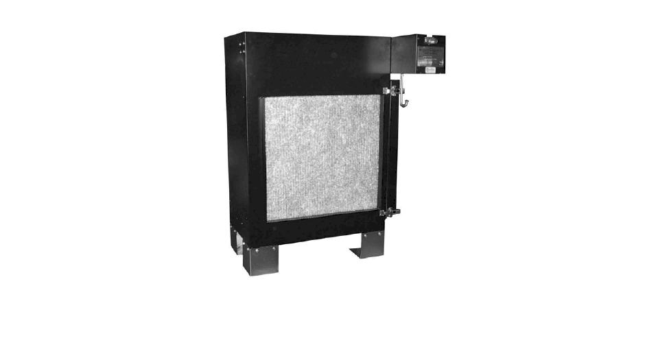
3 TABLE OF CONTENTS PAGE HOW AIRBORNE CONTAMINATION IS REMOVED 3 DIMENSIONS 4 SPECIFICATIONS 6 PLANNING THE INSTALLATION 7 ASSEMBLY & INSTALLATION 10 CHECKOUT 16 MAINTENANCE 18 TROUBLE SHOOTING 21 PARTS IMAGES & PART NUMBERS 24 WARRANTY 27 HOW AIRBORNE CONTAMINATION IS REMOVED A process called Electrostatic Precipitation traps airborne contaminants. The fan draws particulate laden air successively through the prefilter, the cell ionizing section and the cell collector section. The ionizing section imparts an electrical charge to the individual particles that are then drawn by electrostatic forces to the oppositely charged collector plates. Cleaned air is then discharged back into the room. The electronic cells must be washed periodically to maintain efficient performance. 3
4 DIMENSIONS AutoClean 2000 AutoClean 4000
5 AutoClean METRIC CONVERSION FORMULA Ins. to mm Ins. x 25.4 Lbs. to kgs. Lbs. x.455 Ins. w.g. to kpa Ins. w.g. x.2488 CFM to m³/h CFM x Ft² to m² Ft² x.0929 SHIPPING WEIGHT INSTALLED WEIGHT Lb. Kg. Lb. Kg. AutoClean AutoClean AutoClean
6
7 PLANNING THE INSTALLATION INTRODUCTION Clean air is the subject of numerous laws and regulations. Typical requirements in the United States are those put out by the Occupational Safety and Health Administration (OSHA). Private groups, such as the American Society of Heating, Refrigeration and Air Conditioning Engineers (ASHRAE), have also published numerous recommendations. Normally, clean air is defined in regulations and recommendations as air having a limited amount of contaminant in it, commonly expressed as parts per million or milligrams per cubic meter. Approved counteractions are intended to lower or eliminate the amount of contaminants in the air. One of the more common methods of achieving this goal is through the use of air cleaners. AIR CLEANER SIZING The AutoClean air cleaner is usually sized according to the capacity of the air handling system and the desired efficiency. See Fig. 3. The ASHRAE Standard 62-81, Natural and Mechanical Ventilation, gives recommended quantities of ventilation air in terms of 100 percent outdoor air. The Standard recommends as much as 50 CFM per person ventilation air where people are smoking, such as in a cocktail lounge. These recommended outdoor air quantities may be reduced if air cleaning is provided. However, the Standard recommends that in no case shall the outdoor air quality be less than five CFM per person. The reduction in outside ventilation air required represents the potential for savings through the use of clean recirculated air. This potential for savings can be achieved by a system that reduces particulate and gaseous contaminants to within the ASHRAE recommended limits. The AutoClean helps to provide this clean, recirculated air by removing particulate contamination (visible smoke). The reduction in outdoor air used, of course, means a reduction in the amount of heating or cooling required. This reduces both operating cost and equipment wear. Remember that the air cleaner must meet the needs of the user. You are encouraged to use your experience and judgment in the application of this data keeping in mind local codes and minimum air requirements. Airflow recommendation with pressure drop and efficiency rating: F 61 A F 61 B F 61 C Efficiency Water Pressure Drop cfm M 3 / hr cfm M 3 / hr cfm M 3 / hr (Percent) In. KPa , , ,000 16, ,194 12,000 20, Efficiency ratings based on National Bureau of Standards Dust Spot Method and American Society of Heating, Refrigerating and Air-Conditioning Engineers Standard 52-76, using atmospheric dust. FIGURE 3 AutoClean ELECTRONIC AIR CLEANER CAPACITY AND EFFICIENCY COMMERCIAL APPLICATIONS When deciding on the number of air cleaners required for applications such as a restaurant, bowling alley, store, bar or lounge, several conditions must be considered. They are: 1. Air to be cleaned of dust, tobacco smoke, greases, etc. These conditions may require a higher efficiency in the electronic air cleaner installation Capacity cubic feet per minute (cfm) of equipment and system. 3. Method of calculation-must be forced air, distributed evenly to all parts of the controlled area with the required air changes per hour. 4. Maximum number and average number of people that will occupy controlled area.
8
9 TRANSITIONS When adapting the duct to fit the air cleaner, use gradual transitions in duct size to prevent turbulence and to increase efficiency. Duct transitions should not exceed 20 degrees (about 4 per lineal foot) on each side of a fitting. Depending on the installation, it may be necessary to incorporate some or all of the precautions mentioned below: 1. Outdoor air intakes should be hooded or louvered to provide adequate protection from rain and snow. The type of hood used will depend upon the installation and expected weather. 2. Outdoor air intakes should always be equipped with a bird screen. 3. At times it may be desirable to install a prefilter ahead of the electronic air cleaner. This is done to remove contaminants that could be harmful to the air cleaner or might cause excessively fast dirt buildup or arcing in the electronic cell. Fig. 5: TYPICAL INSTALLATION WITH TURNING VANES IN AIR DUCT OUTDOOR AIR When outdoor air is added to the return air duct, sufficient heat must be added to maintain a uniform a temperature between 50 F and 125 F. Two methods are recommended: 1. Baffles. Mixing baffles should be used to mix the outdoor air and the return air before it enters the air cleaner. 2. Preheat Coil. If large amounts of outdoor air are used, it must be heated. An appropriate control system should be used to control the heating element (electric strip heater, steam coil, etc.). Outdoor air intakes should be protected to prevent the introduction of unnecessary contaminants. WATER DAMAGE PROTECTION If the installation is going to be overhead, provide a sheet metal pan with a drain under the entire AutoClean cabinet. This is important in case of water leaks in the ductwork or in the case of a plugged drain. Make certain a drainpipe of sufficient size and slope is roughed-in to the bottom of the air cleaner cabinet at the planned location. AIR CONDITIONING Make certain the cooling coil is installed downstream from the air cleaner cabinet to prevent condensation and chilled air (cooler than 40 F [5 C]) from entering the cell. HUMIDIFIERS Location of the system humidifier is important to the operation of the air cleaner. An evaporative type humidifier may be installed between the furnace warm air duct and the return air duct without affecting the electronic air cleaner. 9
10 ASSEMBLY & INSTALLATION - IMPORTANT - This section includes information for the sheet metal, plumbing and electrical installation. Make certain each person involved with the installation is aware of the appropriate subsections in the manual. - INSTALLATION CHECK LIST - -Transitions -Hot Water Supply Line -Turning Vanes -Pressure Regulator Required? -Components Assembled -Water Strainer Electronic Cells -Drain Connected -Wiring -Check Packing Materials Before Discarding -Activated Carbon Filters Required? - CAUTION - Do NOT connect the power source until after the air cleaner is completely assembled. If the air cleaner must be turned on for an electrical check, be extremely careful in avoiding electrical shock. Also, take care to avoid the air cleaner s moving parts. UNPACKING Remove all shipping cardboard and banding. Be sure to inspect the packaging material before discarding it. WHEN INSTALLING THIS PRODUCT 1. Read these instructions carefully. Failure to follow them could damage the product or cause a hazardous condition. 2. After installation is complete, check out product operation as provided in these instructions. All components are individually packaged and shipped in one large box. Before proceeding, carefully open each carton and visually check for possible damage to the air cleaner components. 1. Cabinet with control box mounted. 2. Electronic cell (1-8 cartons depending on model ordered). 3. Legs with leveler screws and mounting bolts Drain connection. 5. Water strainer. 6. Sequence controller. 7. Accessories, if ordered. PLACEMENT OF THE AIR CLEANER Depending on the placement of the air cleaner (roof top for example) a lifting crane might be necessary. Make sure that the air cleaner and components are properly supported before lifting. If placing on a rooftop make sure there is proper clearance between the rooftop and the air cleaner. This can be achieved with mounting beams or by keeping the lifting supports in place. If the air cleaner is installed in a location where water damage is possible, install a sheet metal pan with drain under the air cleaner cabinet and sloped ductwork.
11 SHEET METAL INSTALLATION Air Distribution and Ductwork The AutoClean operates most efficiently when all system air is delivered across the electronic cell at a uniform velocity. Turning vanes should be added to any return airdrop upstream from the air cleaner. See Fig. 5. Gradual transitions to the AutoClean cabinet are recommended in all ductwork larger or smaller than the cabinet opening. If transitions are used, they should not exceed 20 degrees (4 rise per linear ft. c. Use caulking compound (not furnished) to seal the flange joints and all ductwork joints on both the inlet and outlet sides. Seal all joints for at least 3 ft. from cabinet. FILTER PLACEMENT 1. Slide prefilters into shield channels and push all the way to the back of the cabinet. Install the Air Cleaner Mount the AutoClean Air Cleaner as Follows: 1. Fabricate and install the necessary vanes and transitions. 2. Set the cabinet in position. a. If feet are used, mount the feet on the AutoClean cabinet and adjust all four feet-leveler screws. The bottom of the cabinet must be level. This will provide for proper drainage of water from the bottom of the cabinet. Maximum adjustment is 1 ¼ in. for each leveler screw. b. If hanging brackets are used, make certain the brackets are strong enough to hold the cabinet and the cabinet is attached firmly to the brackets. FIGURE 6 CORRECT CELL ORIENTATION IN AutoClean 2. Insert the electronic cells into the cabinet with THIS SIDE OUT label facing the door opening. Make certain the arrow stamped on the cell points downstream. See Fig Close the door. c. Leave clearance above the control box to remove the cover and apply a wrench to the water strainer. 3. Ductwork preparation a. Drill clearance holes for sheet metal screws in the cabinet flanges which will not cause leaking. Remember that the ductwork must be water-tight near the cabinet. b. Fasten the duct to the inside of the cabinet flange opening with sheet metal screws. 11
12 Model PLUMBING INSTALLATION Recommended Min. Water Pressure during Wash Recommended Hot Water Tank Size (Minimum) Hot Water per Wash Washes per unit of detergent Recommended wash water temperature Maximum water flow 30 psi (206.8 kpa) psi kpa Gallon Liter Gallon Liter Gallon Liter Gal / Liter / min min AutoClean to 160 deg F AutoClean ( 52 to 71 deg C) AutoClean Figure 7 Hot Water and Detergent Requirements Connect the Hot Water Supply Plumbing must comply with applicable codes and regulations. The hot water supply line from the heater to the air cleaner should be ¾ copper pipe for AutoClean 2000 and AutoClean 4000 and 1 for the AutoClean Connect the Detergent Bottle FIGURE 8 TYPICAL INSTALLATION FOR HOT WATER SUPPLY 1. Install the water strainer (supplied) in the hot water line ahead of the water valve. See Fig. 8. The strainer protects the valves and washing jets from clogging. 2. Attach the pressure regulator valve (if water pressure is over 75 psi ) to the water strainer. 3. Connect a faucet, if desired, for checking water temperature. Connect the Drain Connect the drain spud (2 inch) in the base of the AutoClean cabinet to the waste drain. Use a water trap or check the valve to prevent sewer odor from entering the air cleaner base and spreading through the air system. Follow local codes. Test may have to be preformed to check total water quality after air cleaner is installed. FIGURE 9 CONNECTING DETERGENT BOTTLE TO THE CONTROL BOX 1. Insert the plastic hose (supplied) over the metal tube. See Fig. 9. Fasten the hose with a clamp. 2. Insert the hose into the bottle. Make certain the filter screen rests on the bottom of the bottle. 3. Place the bottle on the hanger. 4. Close the top of the bottle with the stopper provided to prevent debris from falling into the detergent. NOTE: Multiple hoses can be inserted into a detergent bottle. Maximum horizontal distance from the air cleaner to the detergent bottle is 20 ft., maximum vertical distance is 7 ft. 12
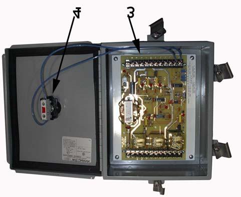
13 ELECTRICAL INSTALLATION All wiring must comply with applicable local codes and ordinances. The power supply to the AutoClean air cleaner must be 120V or 240V, 60 Hz, or V, 50 Hz. Refer to the AutoClean nameplate for the proper voltage for your air cleaner. Use color-coded wires and attach all connections with solderless connectors or to the screw type terminals. Follow figures 10, 11 12, and 13 for making all the appropriate electrical connections. Figures 10 and 11 are of the internal wiring diagrams for each unit. Figures 12 and 13 are of the total wiring diagrams for the units. Notice the three boxes surrounding the Unit, Timer, and HVAC system. All wires that appear outside of these boxes need to be added by the installer. FIGURE 10 INTERNAL WIRING SCHEMATIC FOR AUTOCLEAN 2000 AND
14 FIGURE 11 INTERNAL WIRING SCHEMATIC FOR AUTOCLEAN
15 FIGURE 12 WIRING SCHEMATIC FOR TYPICAL HVAC SYSTEM 15
16 FIGURE 13 WIRING SCHEMATIC FOR EXHAUST FAN SYSTEM CHECKOUT - IMPORTANT - Before putting the AutoClean In-Place Wash Electronic Air Cleaner into service, check through the following items to be sure it is properly installed. 2. If outdoor air is used, care must be taken to prevent direct delivery of cold outside air across the electronic cell. Preheat the air in some manner or mix with return air. 3. Check over the installation for correct sheetmetal, plumbing and electrical work. 4. Turning vanes should be used in duct elbow to provide even air distribution across the cell. 5. When it is necessary to change the duct size close to the air cleaner, use gradual transitions to reduce turbulence. GENERAL COMPONENT INSPECTION 16
17 1. Check for proper orientation of the electronic cells, protective screens and spray shield. Airflow arrows must point downstream. Protective screens must be on both sides of the electronic cells. 2. Be sure that the electronic cells, protective screens and spray shields are clean, dry and free of foreign objects. 3. Be sure the spray manifold is located in the cabinet with nozzles pointed toward the cells. CHECK THE JUNCTION BOX CONNECTIONS Check all electrical connections to make certain they are correct and complete. Refer to the hookup diagrams (Figures 9 through 13). CHECK THE PLUMBING CONNECTIONS Check to be sure all plumbing work including the hot water supply and the drain are correct and will not leak! CHECK THE ELECTRONIC CELLS AND THE POWER SUPPLY With all components in place and the access door closed, energize the system fan and turn on the electronic air cleaner. Check the indicator light on the power door. It should be on. With the power supply energized, momentarily open the access door. When the door opens the indicator light should go out. If the power supply and electronic cells do not check out properly in this procedure, refer to the TROUBLESHOOTING section for additional checks. CHECK THE AUTOMATIC WASHING CYCLE The wash cycle for the electronic cell is controlled by the built-in sequence timer and the washing assembly is operated by a motor. The wash cycle may be manually activated by pressing the button. Remove and visually check cell and screens for dirt. The manifold motor operates a cam and gear assembly to slowly move the manifold (water pipe and spray nozzles) during the wash cycle. Make sure there is complete coverage of the cells during a wash cycle. EAC POWER SUPPLY SYSTEM FAN SEQUENCE TIMER OPERATION SYSTEM SHUT DOWN - 1MIN, WASH - 2MIN, RINSE - 5 MIN, DRY - 45 MIN DETERGENT PUMP HOT WATER VALVE DETERGENT VALVE MANIFOLD MOTOR SYSTEM HEATING SYSTEM COOLING TIME (MINUTES) OPERATES AT DEMAND OF PRIMARY CONTROL CIRCUIT OFF CIRCUIT ON Figure Sequence Timer Operation 17
18 MAINTENANCE - CAUTION - Always disconnect the power to the AutoClean before working on or near the air cleaner. WHEN TO WASH THE ELECTRONIC CELLS To maintain peak performance and efficiency, the electronic cells and spray shields in the electronic air cleaner must be washed regularly. This washing is necessary to remove the dirt particles accumulated during the air cleaning process. The cells and screens should be visually checked for dirt or lint. Experience will probably be the best indicator of how often the cells and screens should be cleaned. For example, when operating in a thick smoke or particularly dirty atmosphere, the cells may need washing twice a week. If the dirt accumulation is light, the period between washings can be lengthened. While the cells in the electronic air cleaner are being washed, a musty, dirty odor combined with the characteristic odor of the detergent may be noticed. This is caused when the accumulated dirt on the cells is washed off by the detergent and hot water spray. It will disappear after the washing is complete. AUTOMATIC WASHING CYCLE The cell wash cycle for the electronic air cleaner is controlled by a built-in timer sequence and may be activated by a master clock. The washing assembly is operated by a motor. NOTE: For 50 Hz models, the timing will be about one-fifth longer. Make sure that enough hot water is available for washing throughout the entire cycle. In installations with multiple electronic air cleaners, it may be necessary to stagger the timing of the wash cycles. This is to assure adequate water pressure for washing. FIGURE 15 PN 38010, ELECTRONIC CELL COMPONENTS. DIMENSIONS IN INCHES [MILLIMETERS SHOWN IN BRACKETS]. MANUALLY STARTING A WASH CYCLE The electronic air cleaner is equipped with an automatic wash control box. When an extra wash cycle is desired, it may be manually started by pushing the labeled button. NOTE: The complete cycle takes about 70 minutes. For the first 15 minutes when water is being sprayed in the electronic air cleaner, the heating or cooling system is automatically turned off. 18
19
20 2. Soak the cells for the time indicated on the cleaning solution label. Before removing the cells, slosh them around several times. 3. Rinse the cells with a fine spray. 4. Soak the cells and let the water drain. If the water draining from the cells feels slippery, they need more rinsing. 5. Inspect the cells for cleanliness. If any dirt remains, it probably indicates that the cells should be washed more frequently. Repeat this soaking procedure, if needed, to get the cells clean. REPLACE THE ELECTRONIC CELLS AND THE SPRAY SHIELDS 1. Replace the electronic cell so that the arrow on the handle-side of the cell points in the direction of the airflow. 2. Insert the spray shields in the channels provided. other short in the charging section, is indicated by the status light on the power door. Broken wires must be replaced. Remove all parts of the broken wire and temporarily use the cell short of one wire until it can be replaced as directed below. See the PARTS LIST to order wires. To replace the ionizing wires, remove the electronic cell from the cabinet and proceed as follows: 1. Remove all of the broken wire from the cell mounting brackets. See Fig Install the new wire. a. Insert the T end of the ionizing wire into the keyhole spring until the hooked end can be secured in the mounting bracket hole. Use a long nose pliers and carefully pull the spring until the hooked end can be secured in the mounting bracket hole. 3. Replace and close the power door. NOTE: The just washed cell may be replaced in the cabinet even though it is still wet. The system light may come on during the normal drying period. IONIZING WIRE REPLACEMENT The fine wire electrodes in the charging section of the electronic cell may break or become damaged. During operation, a broken or deformed wire generally causes a short to ground, possibly with visible arcing or sparking. This condition, or any FIGURE 16 METHOD OF REPLACING THE IONIZING WIRE 20
21
22
23 Too much detergent being used The length of time the detergent pump is on during the wash cycle can be manually changed on the sequence controller by rotating the potentiometer. Mechanical wash system not working (the nozzles are not turning or not traversing along the cells, during the wash and rinse cycle.) The manifold motor operates both the rotation and traversing motion of the jets. Check to see if the manifold motor is operating. If the motor is still not operational check to see if it is getting voltage. If no voltage is getting to the motor trace wiring back and find the break. If voltage is getting to the motor and still no movement is coming from the motor the motor will need to be replaced. Reference the parts list for replacement. Make sure that the linkage is not being stopped by an obstruction. Nothing happens when the start button is depressed Check inside the NEMA box of the sequence controller to see if the LED lights light up when you push the start button. If they do, the sequence controller is not properly wired to the AutoClean. Check the electrical schematics for proper wiring. If the LEDs do not light up when the start button is depressed, check to see that voltage is being supplied to the sequence controller. If voltage is present, but the LEDs won t light, replace the sequence controller. Fan will not turn off during a wash cycle If the fan does not turn off reference the wiring diagram to make sure it wired properly. The fan relay coil should be energized or de-energized by terminal 15 of the sequence controller. 23


24 PARTS IMAGES & PART NUMBERS 24
25 PART NO. ITEM NO. DESCRIPTION 120V, 60 HZ 240V, 60 HZ V, 50 HZ 1 Spray Shield, Pre/Post Filter 24 5/8 x 24 x ¼ Industrial Cell Full Size Industrial Cell Half Size Not Shown Ionizing wires for Industrial Cell sold in 5 pack Sequence Controller 4 Manual Start switch 5 Power Supply Assy 6 Detergent Valve & Solenoid Assy 7 Detergent Pump 8 Water Valve & Solenoid Assy. Not Shown Water Strainer 9 Manifold Motor Not Shown Liquid Detergent (1 gal. [3.78 L]) Not Shown Liquid Detergent-55 gal. [208.2 L] drum Not Shown Cell Coat Not Shown Cell Coat Refill Not Shown Welding Smoke Detergent (5 Gal) Industrial Cell Cleaning Kit Degreaser (5 Gal.)
26 26
27
SPECIFICATIONS - IMPORTANT -
 SPECIFICATIONS - IMPORTANT - THE SPECIFICATIONS GIVEN IN THIS PUBLICATION DO NOT INCLUDE NORMAL MANUFACTURING TOLERANCES. THEREFORE, THIS UNIT MAY NOT MATCH THE LISTED SPECIFICATIONS EXACTLY. ALSO, THIS
INSTALLATION AND OPERATIONS MANUAL
 email: info@uapc.com Main Office: Telephone: 757-461-0077 1140 Kingwood Ave, Norfolk, Virginia 23502 Telefax: 757-461-0808 Branch Offices: Telephone: 704-374-0600 4715 Stockholm Court, Charlotte, NC 28273
F25F Media Air Cleaner
 F25F Media Air Cleaner FEATURES PRODUCT DATA High efficiency media filter captures particles as small as 1.0 micron. Efficiency and arrestance ratings based on the American Society of Heating, Refrigerating
CELDEK Evaporative Cooler Module Installation, Operation, and Maintenance Manual. CELDEK Evaporative Cooler
 CELDEK Evaporative Cooler Module Installation, Operation, and Maintenance Manual CELDEK Evaporative Cooler RECEIVING AND INSPECTION Upon receiving unit, check for any interior and exterior damage, and
Standard and CELDEK Evaporative Cooler Modules Installation, Operation, and Maintenance Manual
 Standard and CELDEK Evaporative Cooler Modules Installation, Operation, and Maintenance Manual Standard Evaporative Cooler CELDEK Evaporative Cooler RECEIVING AND INSPECTION Upon receiving unit, check
Standard and CELDEK Evaporative Cooler Modules Installation, Operation, and Maintenance Manual
 Standard and CELDEK Evaporative Cooler Modules Installation, Operation, and Maintenance Manual Standard Evaporative Cooler CELDEK Evaporative Cooler RECEIVING AND INSPECTION Upon receiving unit, check
OPERATION & MAINTENANCE MANUAL MODEL SC-924A SELF-CONTAINED ELECTRONIC AIR CLEANER IMPORTANT: PLEASE READ MANUAL BEFORE OPERATING UNIT
 OPERATION & MAINTENANCE MANUAL MODEL SC-924A SELF-CONTAINED ELECTRONIC AIR CLEANER IMPORTANT: PLEASE READ MANUAL BEFORE OPERATING UNIT Certified for shock and electrical fire hazard only. MAJOR COMPONENTS
F58F Commercial Duct Mounted Electronic Air Cleaner
 F58F Commercial Duct Mounted Electronic Air Cleaner FEATURES Adapts to airflow from either side. Capacity to 000 cfm (400 m/hr). PRODUCT DATA Solid-state power supply is self-regulating and maintains peak
READ AND SAVE THESE INSTRUCTIONS. Air Boss Model T5200 Custom Packaged Electronic Air Cleaner. TRION
 READ AND SAVE THESE INSTRUCTIONS Air Boss Model T5200 Custom Packaged Electronic Air Cleaner TRION Installation, Operation, & Service Manual Electrostatic Precipitators for Commercial & Industrial Applications
Installation Operation Maintenance
 Installation Operation Maintenance Electronic Air Cleaner Furnace Only Models TFE145A9FR3 TFE175A9FR3 TFE210A9FR3 TFE245A9FR3 18-HE17D7-4 Air Handler Only Models TFE215A1AH3, A9AH3 TFE235A1AH3, A9AH3 TFE260A1AH3,
OPERATION & MAINTENANCE MANUAL MODEL SC SELF-CONTAINED ELECTRONIC AIR CLEANER IMPORTANT: PLEASE READ MANUAL BEFORE OPERATING UNIT
 OPERATION & MAINTENANCE MANUAL MODEL SC-924-1 SELF-CONTAINED ELECTRONIC AIR CLEANER IMPORTANT: PLEASE READ MANUAL BEFORE OPERATING UNIT Certified for shock and electrical fire hazard only. DESCRIPTION
Air Bear Accu-Fit TM. Media Air Cleaner READ AND SAVE THESE INSTRUCTIONS UNITS NOT FOR COMMERCIAL USE. TRION
 READ AND SAVE THESE INSTRUCTIONS UNITS NOT FOR COMMERCIAL USE Air Bear Accu-Fit TM Media Air Cleaner TRION www.trioniaq.com Table of Contents Introduction... 1 Unit Selection Guide... 2 Installation...
F150E Media Air Cleaner
 whole-house air quality system FEATURES F150E Media Air Cleaner PRODUCT DATA APPLICATION F150E W8600A AIRWATCH W8600A AIRWATCH filter change indicator. High efficiency media filter captures particles as
AIR CLEANER A GUIDE TO OPERATING AND MAINTAINING YOUR ELECTRONIC. NOTE TO INSTALLER: This manual should be left with the equipment owner.
 Thi d t t d ith F M k 4 0 4 AIR CLEANER A GUIDE TO OPERATING AND MAINTAINING YOUR ELECTRONIC AIR CLEANER NOTE TO INSTALLER: This manual should be left with the equipment owner. A BREATH OF SPRING-FRESH
F200E Charged-Media Air Cleaner
 whole-house air quality system F200E Charged-Media Air Cleaner PRODUCT DATA FEATURES APPLICATION The F200E Charged-Media Air Cleaner captures a significant amount of the air-borne particles from the air
Residential Duct Mount Builder s Box Media Air Cleaner
 INSTALLATION, OPERATION, AND MAINTENANCE INSTRUCTIONS Residential Duct Mount Builder s Box Media Air Cleaner Part Numbers: P102-BB14A, P102-BB20 IMPORTANT: Read entire instructions before installing the
F52G Return Grille Mounted Electronic Air Cleaner
 F52G Return Grille Mounted Electronic Air Cleaner FEATURES PRODUCT DATA F52G models are available with one electronic cell and a rated capacity of 1000 cfm (1700 m 3 /hr). Electronic cell can be washed
ACT Cartridge Dust Collector
 IOM-101-1 ACT Cartridge Dust Collector Installation and Operation Manual ACT Dust Collectors CAUTION! Accidents happen, be careful and always follow all local and federal regulations! Fires and explosions
F59A Console 3-Speed Electronic Air Cleaner
 Console 3-Speed Electronic Air Cleaner The F59A Console Electronic Air Cleaner cleans the air in enclosed spaces such as offices or homes. A 3-speed fan draws room air through an electronic cell and activated
Duct Heaters volts/1 phase volts/3 phase volts/3 phases volts/3 phases. Flange Type Duct Heater.
 Duct Heaters Synheat duct heaters come in various sizes and dimensions to fit any compartment. There are three types of duct heaters available: open coil, tubular element or finned tubular heating elements
SAFETY AND INSTALLATION MANUAL MODEL 8100
 SAFETY AND INSTALLATION MANUAL ENERGY RECOVERY VENTILATORS MODEL 8100 Provides year-round fresh air Recovers 77% of the apparent heating or cooling energy from the exhausted air See Warnings Page 3 Table
Installation Instructions. For the 18 Built-In Dishwasher and Front Color Panels
 Installation Instructions For the 18 Built-In Dishwasher and Front Color Panels Printed in USA 154232102 Before You Begin DO NOT INSTALL DISHWASHER UNTIL YOU HAVE READ ALL INSTRUCTIONS. FOR YOUR SAFETY,
SAFE DRINKING WATER AND TOXIC ENFORCEMENT ACT
 Installation instructions for your new Spacemaker Laundry WSM2780 Gas Before you begin Read these instructions completely and carefully. IMPORTANT OBSERVE ALL GOVERNING CODES AND ORDINANCES. Note to Installer
ELECTRONIC AIR CLEANER SAFETY AND INSTALLATION MANUAL MODEL 5000 TABLE OF CONTENTS
 ELECTRONIC AIR CLEANER SAFETY AND INSTALLATION MANUAL MODEL 5000 TABLE OF CONTENTS Safety Instructions...2 Specifications...2 Components...3 Installation...4 Operating Instructions...6 Trouble Shooting
2003 METAL FORM MFG. FORM NO: PCIOM/03
 PRECOOLER PRE-CONDENSER EVAPORATIVE COOLERS Installation, Operation, and Maintenance Manual Energy Saver (ES) has a policy of continuous product improvement and reserves the right to change designs and
Electronic Air Cleaner
 by White-Rodgers Electronic Air Cleaner 240 Volt 50/60 Hz SST Super Slim Twin Model Number 10C27S-010 14C27S-010 20C27S-010 UST Universal Slim Twin Model Number 16C27S-010 OWNERS MANUAL WHITE-RODGERS SUPER
Kitchen Exhaust Air Cleaning Systems
 Kitchen Exhaust Air Cleaning Systems Air Quality Engineering, founded in 1973, is proud to offer a continued, superior level of experience in manufacturing complete air filtration systems that provide
Eliminator Series. SE400E and SE800E ELECTRONIC AIR PURIFICATION SYSTEM. Electrostatic Precipitators for Commercial Applications
 ELECTRONIC AIR PURIFICATION SYSTEM Eliminator Series SE400E and SE800E INSTALLATION OPERATION SERVICE Electrostatic Precipitators for Commercial Applications 101 McNeill Road Sanford, NC 27330 (919) 775-2201
ENVIRO UNIT ENGINEERING MANUAL KES SERIES
 ENVIRO UNIT ENGINEERING MANUAL KES SERIES The Cadexair INC. Enviro System (KES) and Recirculation System (KRS) have been designed and constructed specifically for a commercial kitchen exhaust. The units
A. Air Handling Units shall be designed to the specific requirements of the application: Recirculation or 100% Makeup.
 SECTION 23 70 00- CENTRAL HVAC EQUIPMENT PART 1: GENERAL 1.1 PURPOSE: A. This standard is intended to provide useful information to the Professional Service Provider (PSP) to establish a basis of design.
40LM Hz INSTALLATION, START-UP AND SERVICE INSTRUCTIONS CHILLED WATER FAN COIL UNIT
 Carrier International Sdn. Bhd. Malaysia INSTALLATION, START-UP AND SERVICE INSTRUCTIONS CHILLED WATER FAN COIL UNIT 40LM 120-200 50Hz CONTENTS: Physical Data & Dimension 1-3 Safety Considerations 4 Rigging
EAC ELITE ELECTRONIC AIR CLEANER INDOOR AIR QUALITY ENGINEERING DATA FEATURES
 ENGINEERING DATA INDOOR AIR QUALITY EAC ELITE ELECTRONIC AIR CLEANER Bulletin No. 21385 July 3 Supersedes 21274 FEATURES Application Removes up to 94% of all airborne particles passing through it as opposed
INSTALLATION INSTRUCTIONS
 INSTALLATION INSTRUCTIONS FOR RCQD COILS WARNING ISO 9001:2008 92-100105-05-03 SUPERSEDES 92-100105-05-02 TABLE OF CONTENTS Model Number Explanation....................... 2 Unit Specifications..............................
Installation Instructions
 Installation Instructions Before you begin... 2 Location... 2 Recommended grounding instructions... 2 Electrical requirements... 2 Exhaust requirements... 3 Water supply and drain requirements... 3 Please
KINGS COUNTY JAIL EXPANSION PHASE III COUNTY OF KINGS SECTION
 SECTION 237433, PART 1 - GENERAL 1.1 RELATED DOCUMENTS A. Drawings and general provisions of the Contract, including General and Supplementary Conditions and Division 01 Specification Sections, apply to
1 ESMA, Inc. P. O. BOX 734 * SOUTH HOLLAND, IL * (800) * FAX (708)
 * FAX (708)") 1 2 Instructions for Ultrasonic Washer E789 (U.L. Approved) 1. INTRODUCTION The E789 Automatic Ultrasonic Washer automatically performs a cleaning cycle, the major steps of which are: Ultrasonic cleaning
1 2 Instructions for Ultrasonic Washer E789 (U.L. Approved) 1. INTRODUCTION The E789 Automatic Ultrasonic Washer automatically performs a cleaning cycle, the major steps of which are: Ultrasonic cleaning
INSTALLATION INSTRUCTIONS TXV Horizontal Slab Coils WLSH
 TXV Horizontal Slab Coils WLSH These instructions must be read and understood completely before attempting installation. It is important that the Blower and Duct System be properly sized to allow the system
INSTALLATION, OPERATION AND SERVICE MANUAL MIGHTY ION MODEL MI SERIES
 1135 Lance Road Norfolk, VA 23502-2429 Telephone: 757-461-0077 a.k.a. Universal Air Precipitator Corporation Telefax: 757-461-0808 Quality Equipment and Service Since 1962 email: info@uapc.com INSTALLATION,
INSTALLATION INSTRUCTIONS ENERGY RECOVERY VENTILATOR WITH EXHAUST
 INSTALLATION INSTRUCTIONS ENERGY RECOVERY VENTILATOR WITH EXHAUST MODELS: WGERV-A3 WGERV-C3 WGERV-A5 WGERV-C5 BARD MANUFACTURING COMPANY Bryan, Ohio 4356 Since 1914...Moving ahead, just as planned. Manual:
Installation, Start-up and Service Instruction ELECTRONIC AIR CLEANER
 Installation, Start-up and Service Instruction 901K Cancels: II 901K-12-2 II 901K-12-3 6-15-94 NOTE: Read the entire instruction manual before starting the installation. SAFETY CONSIDERATIONS Improper
Installation Guide. Dehumidification. Fresh Air Ventilation. Compact Size. Energy Efficient. RXID-AW90A Whole House Dehumidifier
 RXID-AW90A Whole House Dehumidifier with fresh air ventilation Installation Guide Dehumidification Fresh Air Ventilation Compact Size Energy Efficient The whole house dehumidifier integrates highcapacity
Electronic Air Cleaner Model Number CSC1000 OWNER S MANUAL. Installation Operation Basic Service Guide Technical Repair Guide Repair Parts
 Electronic Air Cleaner Model Number CSC1000 UL Listed CSA Certified OWNER S MANUAL Installation Operation Basic Service Guide Technical Repair Guide Repair Parts Please read and familiarize yourself with
F116 (Series 16000) Self-Contained Ductable Commercial Air Cleaner
 Self-Contained Ductable Commercial Air Cleaner") F116 (Series 16000) Self-Contained Ductable Commercial Air Cleaner FEATURES PRODUCT DATA Variety of filter configurations available to customize the air cleaner for any application. Three-speed direct
F116 (Series 16000) Self-Contained Ductable Commercial Air Cleaner FEATURES PRODUCT DATA Variety of filter configurations available to customize the air cleaner for any application. Three-speed direct
READ AND SAVE THESE INSTRUCTIONS. Air Boss ATS Series Electrostatic Precipitators Commercial & Industrial Applications. TRION
 READ AND SAVE THESE INSTRUCTIONS Air Boss ATS Series Electrostatic Precipitators Commercial & Industrial Applications TRION www.trioniaq.com Installation, Operation, & Service Manual Electrostatic Precipitators
INSTALLATION INSTRUCTIONS Cased N Coil, Horizontal ENH4X
 INSTALLATION INSTRUCTIONS Cased N Coil, Horizontal ENH4X NOTE: Read the entire instruction manual before starting the installation. TABLE OF CONTENTS PAGE SAFETY CONSIDERATIONS... 1 INTRODUCTION... 1 INSTALLATION...
INSTALLATION INSTRUCTIONS TXV Horizontal Duct Coils EHD
 TXV Horizontal Duct s EHD These instructions must be read and understood completely before attempting installation. It is important that the Blower and Duct System be properly sized to allow the system
T1001 Module T2002 Module T1300 T2600. Air Boss T-Series Custom Packaged Electronic Air Cleaner READ AND SAVE THESE INSTRUCTIONS
 T1001 Module T2002 Module T100 T2600 READ AND SAVE THESE INSTRUCTIONS Air Boss T-Series Custom Packaged Electronic Air Cleaner TRION Installation, Operation, & Service Manual Electrostatic Precipitators
Table of Contents. List of Figures
 1 P a g e Table of Contents Introduction. 3 Receiving....4 Description Model G3 & G4...5/6 Water Production Flow Chart...7 Positioning the Cooler...8 Water Cooler Connections..9 Feed Water Connection....10
Installation Instructions
 FAVXXR6C2100-A01 Vent Damper and Control Installation Instructions FAMILIARIZE YOURSELF WITH THE INSTALLATION INSTRUCTIONS BEFORE STARTING ATTENTION INSTALLER: This product must be installed by a qualified
HE360 Humidifier Installation Kit
 HE360 Humidifier Installation Kit INSTALLATION INSTRUCTIONS WELCOME To the comfortable world of humidified air. When you use your Honeywell humidifier, you notice that your skin is not as dry, and that
FOR PRODUCT/WARRANTY REGISTRATION Go to Click on SUPPORT at the top of homepage Click on PRODUCT REGISTRATION
 Salvajor Commercial Disposers For All Models: 75, 00, 50, 200, 300, 500, 750 Models 75-200 Models 300-750 2 Typical Installations & Installation of Cone Bowl or Sink Collar 3 Attaching Disposer to Cone
Installation & Maintenance Instructions
 B2451 & B2452 Series Wall Heaters SPECIFICATIONS MODEL VOLTS HZ AMPS WATTS BTUH B2451 120 60 12.5 1500 5120 B2452 240 60 8.3 2000 6826 208 60 7.2 1500 5120 DIMENSIONS OVERALL Height - 14 1/4 Width - 11
INSTALLATION INSTRUCTIONS TXV Horizontal Duct Coils EHD
 TXV Horizontal Duct s EHD These instructions must be read and understood completely before attempting installation. It is important that the Blower and Duct System be properly sized to allow the system
Installation Instructions
 Installation Instructions For the 18" Built-In Dishwasher Sears, Roebuck and Co. Sears Canada, Inc. Hoffman Estates, IL 60179 U.S.A. Toronto, Ontario, Canada M5B 2B8 154435201 Before You Begin DO NOT INSTALL
1 P a g e. G4 Counter Top OPERATION MANUAL
 1 P a g e G4 Counter Top OPERATION MANUAL Table of Contents Introduction. 3 Receiving....4 Description Model G3 & G4...5/6 Water Production Flow Chart...7 Positioning the Cooler...8 Water Cooler Connections..9
Installation Instructions
 Installation Instructions For Cased Coils Upflow-Downflow Heating-Cooling CK5A CK5B SUPPLY RETURN EVAPORATOR COIL DOWNFLOW UPFLOW SUPPLY Fig. 1 Typical Coil Installation NOTE: Read the entire instruction
442 Chapter 16. Figure 16-5 Gas leak detection
 BRORANE BRORANEBRORANEBRORANEBRORANEBRORANEBRORANEBRORANE 442 Chapter 16 Tur n e r BRORANE FUEL EBRORANEBRORANEBRORANEBRORANEBRORANE Figure 16-5 Gas leak detection is easy. This sensitive halide detector
READ AND SAVE THESE INSTRUCTIONS. Grease Viper Series Electrostatic Precipitators Commercial & Industrial Applications. TRION
 READ AND SAVE THESE INSTRUCTIONS Series Electrostatic Precipitators Commercial & Industrial Applications TRION Installation, Operation, & Service Manual Electrostatic Precipitators for Commercial & Industrial
INSTALLATION GUIDE Dual Fuel Ranges
 INSTALLATION GUIDE Dual Fuel Ranges Contents Wolf Dual Fuel Ranges......................... 3 Safety Instructions............................ 4 Dual Fuel Range Specifications.................. 5 Dual Fuel
S150 S300 CONSTRUCTION HEATERS. Rev: August 15, 2008 SERVICE AND MAINTENANCE MANUAL No PLEASE RETAIN FOR FUTURE REFERENCE PRODUCTS
 S150 & S300 CONSTRUCTION HEATERS Rev: 2.7.2 August 15, 2008 SERVICE AND MAINTENANCE MANUAL No. 934-6637 PLEASE RETAIN FOR FUTURE REFERENCE PRODUCTS A DIVISION OF HAUL-ALL EQUIPMENT LTD. 4115-18 Avenue
COPPER INSERT INSTALLATION INSTRUCTIONS, USE AND CARE GUIDE
 COPPER INSERT INSTALLATION INSTRUCTIONS, USE AND CARE GUIDE DESIGNER SERIES MODELS Model Width CFM Type of Motor & Blower VSL430 BF 28-3/8" * Remote VSL436 BF 34-3/8" * Remote VSL442 BF 40-3/8" * Remote
MODELS B1PA024, 030 AND 036
 STELLAR 2000 SINGLE PACKAGE HEAT PUMPS INSTALLATION INSTRUCTION Supersedes: 511.26-N1Y (892) 511.26-N1Y (893) MODELS B1PA024, 030 AND 036 035-11622 GENERAL YORK Model B1PA units are factory assembled heat
INSTALLATION MANUAL. '»'"',' ','"* Self-contained Ceiling Mount Electronic Air Cleaner.
 . '»'"',' ','"* '^ Self-contained Ceiling Mount Electronic Air Cleaner. Fits T-Bardrop ceiling or mounts directly to standard ceiling. Quieter performance* Adjustable discharge louvers on 4 sides. Cleans
IMPORTANT INSTRUCTIONS READ & SAVE
 5,000W/240V WALL / CEILING MOUNTED GARAGE HEATER WITH ELECTRONIC CONTROLLER AND REMOTE OWNER S MANUAL IMPORTANT INSTRUCTIONS READ & SAVE Model: PH-950NR PET OWNERS WARNING: The health of some small pets
HE220, HE260 Humidifier Installation Kit
 HE220, HE260 Humidifier Installation Kit WELCOME To the comfortable world of humidified air. When you use your Honeywell humidifier, you notice that your skin is not as dry, and that your scratchy throat
Warranty. Installation Operation Maintenance
 Warranty ELECTRONIC AIR CLEANER LIMITED FIVE-YEAR WARRANTY This limited warranty covers TRION Residential Type Electronic Air Cleaners, excluding ductwork, wiring, and installation. TRION warrants that
ELECTRIC DRYER INSTALLATION INSTRUCTIONS
 ELECTRIC DRYER INSTALLATION INSTRUCTIONS Para una version de estas instrucciones en español, visite www.whirlpool.com Table of Contents DRYER SAFETY... 2 Installation Requirements... 3 Tools and Parts...
READ AND SAVE THESE INSTRUCTIONS. SE400E & SE800E Smoke Eliminator. TRION
 READ AND SAVE THESE INSTRUCTIONS SE400E & SE800E Smoke Eliminator TRION www.trioniaq.com Smoke Eliminator SE400E & SE800E Table of Contents Design Introduction... 2 Specifications... 2 The Filter System...
WCD-1. Evaporative Cooling Modules. WCD Series. Alton. Keeps You. Cool
 WCD-1 Evaporative Cooling Modules WCD Series Alton Keeps You Cool TURBOCELL WCD SERIES EVAPORATIVE COOLING MODULES THE LATEST IN COOLING TECHNOLOGY In many types of industries where efficient, low-cost
INSTALLATION AND OPERATION MANUAL STEAM COIL BASE CONVECTION STEAMER MODEL SCX-16
 INSTALLATION AND OPERATION MANUAL STEAM COIL BASE CONVECTION STEAMER MODEL SCX-16 CROWN FOOD SERVICE EQUIPMENT LTD. 70 OAKDALE ROAD, DOWNSVIEW, (TORONTO), ONTARIO, CANADA, M3N 1V9 TELEPHONE: (416) 746-2358,
Installation & Service Instructions for Jackson & Church Flexaire Packaged Furnaces SDF-125 thru SDF-400 Gas Firing
 Installation & Service Instructions for Jackson & Church Flexaire Packaged Furnaces SDF-125 thru SDF-400 Gas Firing Important: To protect the unit and avoid damage to the heat exchanger, the blower speed
EVAPORATIVE AIR COOLER SERVICE MANUAL
 EVAPORATIVE AIR COOLER SERVICE MANUAL CAUTION: Before servicing the unit, read the Safety Precautions in this manual. Only for authorized service. MODEL NO.: CL30XC & CHL30XC (INDOOR USE ONLY) CONTENT
VENTING CLEARANCES. BBT NORTH AMERICA Bosch Group. Bosch Water Heating 340 Mad River Park, Waitsfield, VT TWH-V-26 page 1 of 6 rev 01/06
 page 1 of 6 VENTING CLEARANCES The vents should not be obstructed and all joints properly fitted. Floors, ceilings and walls must be cut or framed to provide necessary clearance to vents. Metal strippings
ENVIRONMENTAL CONTROL UNIT (ECU) PART NUMBER OPERATIONS AND MAINTENANCE MANUAL
 PART NUMBER OPERATIONS AND MAINTENANCE MANUAL") ENVIRONMENTAL CONTROL UNIT (ECU) PART NUMBER 2001829 OPERATIONS AND MAINTENANCE MANUAL Prepared by: 860 Douglas Way PO Box 530 Natural Bridge Station, VA 24579 1.0 SCOPE: This Operations and Maintenance
ENVIRONMENTAL CONTROL UNIT (ECU) PART NUMBER 2001829 OPERATIONS AND MAINTENANCE MANUAL Prepared by: 860 Douglas Way PO Box 530 Natural Bridge Station, VA 24579 1.0 SCOPE: This Operations and Maintenance
TABLE OF CONTENTS. NOTE: Read the entire instruction manual before starting the installation. TROUBLESHOOTING... 13
 R 410A Duct Free Split System Air Conditioner and Heat Pump Product Family: DFS4(A/H) System, DFC4(A/H)3 Outdoor, DFF4(A/H)H Indoor NOTE: Read the entire instruction manual before starting the installation.
INSTALLATION & MAINTENANCE MANUAL FOR QuickDraw
 INSTALLATION & MAINTENANCE MANUAL FOR QuickDraw SEMI-INSTANTANEOUS ENERGY: STEAM TO WATER U-TUBE SINGLE-WALL & DOUBLE-WALL HEAT EXCHANGERS FLOOR DRAIN Typical Construction Figure 34-1 FLOOR DRAIN 1. U-tube
OPERATING INSTRUCTIONS MANUAL (Please retain for future reference) FVO-200 INDIRECT FIRED SPACE HEATERS
 FVO-200 INDIRECT FIRED SPACE HEATERS") OPERATING INSTRUCTIONS MANUAL (Please retain for future reference) For FVO-200 INDIRECT FIRED SPACE HEATERS CERTIFIED FOR USE IN CANADA AND U.S.A. As per CSA B140.8 Portable Oil Fired Heaters / CSA B140.02003
OPERATING INSTRUCTIONS MANUAL (Please retain for future reference) For FVO-200 INDIRECT FIRED SPACE HEATERS CERTIFIED FOR USE IN CANADA AND U.S.A. As per CSA B140.8 Portable Oil Fired Heaters / CSA B140.02003
PACKAGED ELECTRONIC AIR CLEANER. Air Boss T-Series. Model T5200 INSTALLATION OPERATION SERVICE. Electrostatic Precipitator for Industrial Applications
 PACKAGED ELECTRONIC AIR CLEANER Air Boss T-Series Model T5200 INSTALLATION OPERATION SERVICE Electrostatic Precipitator for Industrial Applications 101 McNeill Road Sanford, NC 27330 (919) 775-2201 Fax:
installation and start-up instructions HUMIDIFIERS AND HUMIDISTAT
 installation and start-up instructions HUMIDIFIERS AND HUMIDISTAT HUM Cancels: II 912D-56-3 II HUM-56-1 7-98 MODEL HUMBBLFP1025-A-- FAN-POWERED HUMIDIFIER MODEL HUMBBLBP2018-A-- BYPASS HUMIDIFIER MODEL
Installation Instructions
 CNPVP CNRVP Cased N Coils Upflow --- Downflow Heating --- Cooling Installation Instructions NOTE: Read the entire instruction manual before starting the installation. TABLE OF CONTENTS PAGE SAFETY CONSIDERATIONS...
Installation Instructions
 CNPVP CNRVP Cased N Coils Upflow --- Downflow Heating --- Cooling Installation Instructions NOTE: Read the entire instruction manual before starting the installation. TABLE OF CONTENTS PAGE SAFETY CONSIDERATIONS...
HVAC 101: Residential Typical system components & cleaning techniques
 : Typical system components & cleaning techniques Copyright 2018 NADCA, All Rights Reserved No part of this publication may be reproduced or distributed by any means, electronic or mechanical, including
INSTALLATION INSTRUCTIONS AH12 WALL MOUNT HOOD
 Read and Save These Instructions All Hoods Must Be Installed By A Qualified Installer INSTALLATION INSTRUCTIONS AH12 WALL MOUNT HOOD Read All Instructions Thoroughly Before Beginning Installation WARNING
Installation Instructions
 Installation Instructions For Cased and Uncased Coils Upflow-Downflow Heating-Cooling CK5A, CK5B Cased CJ5A Uncased SUPPLY RETURN EVAPORATOR COIL DOWNFLOW UPFLOW SUPPLY Fig. 1 Typical Coil Installation
READ AND SAVE THESE INSTRUCTIONS
 READ AND SAVE THESE INSTRUCTIONS WARNING TO REDUCE THE RISK OF FIRE, ELECTRIC SHOCK, OR INJURY TO PERSONS, OBSERVE THE FOLLOWING: 1. Use this unit only in the manner intended by the manufacturer. If you
CS/CD/CP AIR COOLED CONDENSING UNITS (P/N E207120C R2)
") CS*/CD*/CP* Series Air Cooled Condensing Units Operating and Installation Manual CS/CD/CP AIR COOLED CONDENSING UNITS (P/N E207120C R2) TABLE OF CONTENTS I. Receipt of Equipment 2 II. Piping...4 III. System
CS*/CD*/CP* Series Air Cooled Condensing Units Operating and Installation Manual CS/CD/CP AIR COOLED CONDENSING UNITS (P/N E207120C R2) TABLE OF CONTENTS I. Receipt of Equipment 2 II. Piping...4 III. System
Duct Mount Electronic Air Cleaner
 Warranty Limited Warranty This product comes with a two (2) year limited warranty on parts. The warranty provides that a replacement will be furnished for any part of the product that fails in normal use
Internet Version for Reference Only INDUCED DRAFT COMMERCIAL WATER HEATERS SUPPLEMENT INSTRUCTIONS TO PART #
 INDUCED DRAFT COMMERCIAL WATER HEATERS SUPPLEMENT INSTRUCTIONS TO PART #238-39387-00 THIS INSTRUCTION SUPPLEMENT IS ONLY INTENDED TO GIVE INSTALLATION INSTRUCTIONS AND INFORMATION RELATED TO THE INDUCED
OPERATION INSTRUCTIONS ENERGY RECOVERY VENTILATOR WITH EXHAUST. For Use With Bard 2 Through 5 Ton QW*S Series
 OPERATION INSTRUCTIONS ENERGY RECOVERY VENTILATOR WITH EXHAUST Models: 90-007 QWSERV 90-08 QWSERV with Intelligent Defrost For Use With Bard Through 5 Ton QW*S Series Bard Manufacturing Company, Inc. Bryan,
5.0 Installation Instructions
 5.0 Installation Instructions 5.1 Location Within the laboratory, pharmacy, etc., the ideal location of the biological safety cabinet is away from personnel traffic lanes, air vents (in or out), doors
The Enviro-Clean Air Scrubber keeps the Atmosphere Clear and Creates Clean Air
 EXHAUST FAN Scrubber exhaust filtration system consists of a baffle section with water spray, a coarse filter section and a bag filter section to be installed in line with a grease duct. The enclosure
Model 8120 and 8126 Safety & Installation Instructions
 Ventilation Controller Model 8120 and 8126 Safety & Installation Instructions FAMILIARIZE YOURSELF WITH THE INSTALLATION INSTRUCTIONS BEFORE STARTING DANGER ATTENTION INSTALLER: To prevent serious injury
SPX SERIES PACKAGED AIR CONDITIONING/HEAT PUMP UNITS INSTALLATION, OPERATION AND MAINTENANCE INSTRUCTIONS
 SPX SERIES PACKAGED AIR CONDITIONING/HEAT PUMP UNITS INSTALLATION, OPERATION AND MAINTENANCE INSTRUCTIONS **WARNING TO INSTALLER, SERVICE PERSONNEL AND OWNER** Altering the product or replacing parts with
FLOW-THROUGH FURNACE HUMIDIFIER
 FLOW-THROUGH FURNACE HUMIDIFIER Installation Warranty Maintenance Troubleshooting Guide 2 Installation READ COMPLETE INSTALLATION INSTRUCTIONS AND TEMPLATE BEFORE STARTING Attention Installer: Installation
42 X 24 FT 48 X 24 FT
 42 X 24 FT 48 X 24 FT 12 CFM 25 CFM Read this manual before operating equipment Warning! Do not use sand or abrasive containing silica in Econoline machines. Failure to comply will result in a voided warranty.
Installation Instructions Remote Blowers
 Installation Instructions Remote Blowers Models: REMP3, REMP16 Suitable for use in a household cooking area. Suitable for use with solid state controls. To complete this blower, a Dacor hood assembly or
INSTALLATION MANUAL UN-CASED A COILS UPFLOW FOR COOLING/HEAT PUMPS FLEX COILS FOR FIELD INSTALLED TXV MODELS: UC LIST OF SECTIONS LIST OF FIGURES
 INSTALLATION MANUAL UN-CASED A COILS UPFLOW FOR COOLING/HEAT PUMPS FLEX COILS FOR FIELD INSTALLED TXV MODELS: UC ISO 9001 Certified Quality Management System SAFETY................................................
INSTALLATION INSTRUCTIONS ENERGY RECOVERY VENTILATOR WITH EXHAUST MODELS: WFERV. Bard Manufacturing Company, Inc.
 INSTALLATION INSTRUCTIONS ENERGY RECOVERY VENTILATOR WITH EXHAUST MODELS: WFERV Bard Manufacturing Company, Inc. Bryan, Ohio 4356 Since 1914...Moving ahead, just as planned. Manual: 21-495 Supersedes:
INSTALLATION INSTRUCTIONS UNDERCOUNTER DISHWASHERS
 INSTALLATION INSTRUCTIONS UNDERCOUNTER DISHWASHERS VIKING 111 Front Street Greenwood, Mississippi 38930 USA (662) 455-1200 IMPORTANT - PLEASE READ AND FOLLOW Before beginning - please read these instructions
B.C.S. Shop Heaters 26, 30 & 36 (36 shown)
") BIOMASS COMBUSTION SYSTEMS, INC. 67 MILLBROOK ST., SUITE 502 WORCESTER, MA 01606 508-798-5970 - FAX 508-798-5971 B.C.S. Shop Heaters 26, 30 & 36 (36 shown) INSTALLATION MANUAL HAND FIRED SYSTEMS 8-09 Biomass
BIOMASS COMBUSTION SYSTEMS, INC. 67 MILLBROOK ST., SUITE 502 WORCESTER, MA 01606 508-798-5970 - FAX 508-798-5971 B.C.S. Shop Heaters 26, 30 & 36 (36 shown) INSTALLATION MANUAL HAND FIRED SYSTEMS 8-09 Biomass