Visit our web site at
|
|
|
- Adelia O’Brien’
- 5 years ago
- Views:
Transcription

1
2
3 TABLE OF CONTENTS National Environmental Products ltd. Tel: Fax:(514) Customer Service Fax: (514) Business hours: from Monday to Friday, 8:00A.M. to 5:00P.M. (North American Eastern time) heater@neptronic.com Introduction I.1 Heater Selection Software I.2 Manufacturing I.3 Overview II.1 Description of Components II.3 Mechanical Construction II.5 Frame II.6 Control Panel II.8 Special Electric Heaters II.10 Materials & Dimensions II.11 Heating Elements II.12 Selection & Installation Tips II.14 Electrical Construction III.1 Electric Control III.2 Pneumatic Control III.3 Electrical Components III.4 Neptronic HEC Controller III.7 Typical Wiring Diagrams III.8 Legend III.10 Thermostats IV.1 ON/OFF Thermostats IV.2 White Rogers IV.2 Honeywell IV.3 Modulating Thermostats IV.4 X IV.4 DS IV.4 PTA IV.5 Option Summary Sheet & Nomenclature V.1 Specification Form V.3 Open Coil Element Heater V.3 Tubular Element Heater V.5 General Conditions of Sales & Warranty V.7 Formulas & Conversions V.8 Installation Instructions annex
4


5 INTRODUCTION Founded over 30 years ago, the company occupies a modern 80,000 square foot facility on 200,000 square feet of land. Located in the heart of Montreal, Canada, with easy access to the main throughways and international airports. Over 130 people are employed at the Head Office and Factory. Neptronic is the trade name for a complete range of products available for heating, ventilation and air conditioning applications. Along with electric heaters, NEP designs, manufactures and distributes electric and gas steam humidifier, as well as electronic damper actuators, actuated valves and controls. NEP holds several patents, notably for the ENERDRIVE system, a fail safe device available in selected damper actuator models as well as for the AFEC system in the SK300 series electric humidifier. Recently, 2 more important patents were approved, one for the siphon system for the SKR residential humidifier and the latest for the unique HEC electric heater controller I.1


6 HEATER SELECTION SOFTWARE n e p t r o n i c Neptronic is the first and only manufacturer of electric heaters to offer to its clients, the possibility to obtain specifications directly on our web site: Our selection software allows access to technical data and formulas to specify Neptronic heaters and much more. Whether you are an engineer or a contractor, our software allows you to very easily select the required electric heater by entering the basic data (duct dimensions, airflow, power, voltage, number of stages, control signals, etc.) from a user friendly window. The selection software then calculates the optimum specifications for each electric heater. The complete and precise heater specifications, as well as the approval list, may be edited or inserted in the project file. You are in control of all your projects and will be able to assign your own reference numbers. Modifications are made directly from your computer. To obtain a price, forward the selected list of heaters to one of our representatives for fast and efficient service. The unique selection software allows data to be transferred automatically between the representatives and our manufacturing plant, eliminating errors that can arise during data transfer. I


7 MANUFACTURING The Neptronic electric heater is manufactured using the most advanced technologies available: Total automation from design to production using integrated CAD/CAM systems not only assures maximum efficiency, but also prevents errors in the transfer of plans and specification data between the client, the R&D department and manufacturing personnel. The most advanced CNC technology for sheet metal fabrication is used in manufacturing the heaters. All these factors were key in designing a complete line of electric heaters that are sturdy, easy to install and which include standard features that our competitors offer only as options, such as control panel doors with removable hinges. Modern equipment allows us to respond in record time to your needs and to the most demanding specifications. This infrastructure is supported and managed by our highly skilled specialists to whom quality workmanship is of utmost importance I.3
8 I


9 OVERVIEW section II II.1

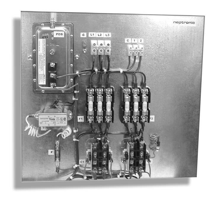
10 OVERVIEW n e p t r o n i c Disconnect switch 2 knockouts Slip-In type frame Control terminal block Line voltage terminal block Stage fuses Transformer Contactor Control panel fig.2.1 Protective screen II

 Proportionally controls the amount of power transmitted to the heating elements. Allows quiet operation and is exceptionally reliable.")


11 DESCRIPTION OF COMPONENTS Magnetic Contactor Provides power to the individual stages of the heater. Standard Transformer Supplies power to the control circuit. Supplied with a fuse. Standard Automatic Reset Thermal Cut-Out An automatic reset, primary safety device. Removes power from elements if overheating occurs. Standard Airflow Switch Safety component used to prevent a heater from operating if there is no airflow. Standard for ON/OFF heaters Solid State Relay (SSR) Proportionally controls the amount of power transmitted to the heating elements. Allows quiet operation and is exceptionally reliable. Standard for proportional heaters Manual Reset Thermal Cut-Out A secondary safety device which removes power to the elements if overheating occurs. Standard when required by code, otherwise optional Neptronic HEC Electronic Controller A unique control and safety component. Controls and optimizes the power transmitted to the heating elements according to the duct temperature and air flow. Standard for proportional heaters. Pneumatic Electric Switch Converts a pneumatic ON/OFF signal to an electric signal. Standard for heaters with pneumatic ON/OFF signal Pneumatic Electric Control Converts a proportional pneumatic control signal to a proportional electric signal. Standard for proportional units with pneumatic signal Disconnect Switch Cuts the power supply to the heater in order to safely perform installation and maintenance tasks. Standard when required by code, otherwise optional Fuses Protect the total load and/or the individual heater stages. Standard when required by code, otherwise optional Mercury Contactor Provides power to the individual stages of the heater. Allows quiet, reliable operation. Optional II.3
12 II
13 MECHANICAL CONSTRUCTION II.5
14 FRAME n e p t r o n i c Slip-In Electric Heater - Type I The slip-in type electric heaters are designed so that the entire frame can be inserted into the duct. Advantages of slip-in electric heaters: A system using a slip-in heater permits the installation of the entire ventilation duct system before the heaters become available. Retrofits are much simpler, smaller dimension slip-in heaters require no extra supports. To order a Neptronic slip-in heater, specify the dimensions of the duct and the selection software will automatically calculate the optimum heater dimensions. Installation: fig.2.2 Allow for a proper sized opening on one side of the duct, see fig. 2.2, as well as installation clearances to avoid any obstructions around the duct. The Neptronic slip-in heater has a standard 1" (25.4mm) flange on each side of the control box and can be attached directly to the duct with sheet metal screws. Flanged Electric Heater - Type F Flanged heaters are designed so that the heater is an integral part of the duct work. The heater frame is attached to matching duct flanges, see fig Standard 1" (25.4mm) on the heater frame are used to attach it to the duct. Flanged heater dimensions match the dimensions of the duct. Heaters requiring extra support or for large heaters, custom flanges can be provided. Installation: fig.2.3 The Neptronic electric heater comes with 1" (25.4mm) standard flanges installed around the frame and on each side of the control box. It can be attached directly onto the duct with sheet metal screws. Note: Round collar option available with flanged electric heater type F II
15 FRAME Round Collar option Round collar electric heaters are available for installation on round duct systems with a standard diameter of 6" to 24" (152mm to 609mm). They are provided with one male and one female adapter for ease of installation. Installation: The Neptronic round collar electric heater comes with a 1" (25.4mm) extension on each side of the frame. The heater is attached directly onto the duct using sheet metal screws. fig.2.4 Zero Clearance Construction All Neptronic heaters are designed and approved for zero clearance to combustible material. Zero clearance construction means that there is no restriction on the distance between combustible materials and the section of the duct housing the heater, or the heater itself. The control panel must be accessible for servicing. Horizontal or Vertical Mounting Neptronic electric heaters are designed to be installed in either horizontal or vertical ducts. Please specify the airflow direction with an H for horizontal and a V for vertical to ensure correct orientation of the components in the control panel. Vertical Horizontal standard option option standard fig.2.5 fig.2.6 Optional Accessories: Protective Screens Optional protective screens are available to prevent accidental contact with the heating elements. Option 10 or 01: Protective screens on one side only - 10 left of the control panel, 01 right of the control panel. Option 11: Protective screens on both sides of the heater II.7
16 CONTROL PANEL n e p t r o n i c Standard Control Panel The control panel attached to the heater exceeds the frame dimensions by 1" (25.4mm) on the top and bottom. If installation conditions do not allow for this standard extension a control panel with dimensions equal to the heater frame can be provided. The standard extension of the control panel is to the left. If installation conditions do not permit the extension to the left you must specify the direction for the extension of the control panel. Control Panel Options Bottom Control Panel A bottom control panel can be supplied, when required for easy installation and maintenance. This option is available for all heaters (Slip-in, flanged and round collar) of small dimensions. fig.2.7 Insulated Control Panel INSULATION 1 (25.4mm) An insulated control panel is recommended for high duct temperatures. Insulation material, 1" (25.4mm) thick is installed between the panel and the hot area to prevent condensation on electrical components. fig.2.8 Remote Control Panel In certain cases it may be more convenient to install the control panel remotely from the heater or in a separate room. A remote control panel can be supplied upon request. fig.2.9 II
17 CONTROL PANEL Enclosure Types (control panels) Nema 1 (IP 10) Protected against access Enclosures constructed for indoor use to provide a degree of protection to personnel against incidental contact with the enclosed equipment and to provide a degree of protection against falling dirt. This enclosure type is standard on Neptronic electric heaters. Nema 12 (IP 52) Dust-protected Enclosures constructed (without knockouts) for indoor use to provide a degree of protection to personnel against incidental contact with the enclosed equipment; to provide a degree of protection against falling dirt; against circulating dust, lint, fibers, as well as water spray and light splashing of liquids, water infiltration, oil or non corrosive liquid refrigerant. Nema 4 (IP 56) Protected against splashing water Enclosures constructed for either indoor or outdoor use to provide a degree of protection to personnel against incidental contact with the enclosed equipment; to provide a degree of protection against falling dirt, rain, sleet, snow, windblown dust, splashing water, and hose-directed water; and that will be undamaged by the external formation of ice on the enclosure. Nema 4X (IP 65) Protected against corrosion Enclosures constructed for either indoor or outdoor use to provide a degree of protection to personnel against incidental contact with the enclosed equipment; to provide a degree of protection against falling dirt, rain, sleet, snow, windblown dust, splashing water, and hose-directed water, and corrosion; and that will be undamaged by the external formation of ice on the enclosure. The control panel and/or the electric heater are constructed in stainless steel for this option II.9
18 SPECIAL ELECTRIC HEATERS n e p t r o n i c Special electric heaters Heater with Cold Section In special cases a cold section in the air duct is required. For example, when air flow has been altered near the area where the heater is located. In this case the heater will be built in order to adapt to this constraint. Specify the location and dimensions of the cold section(s) using the control panel as your reference point. (see fig. 2.10) fig.2.10 Large Heaters Heaters whose dimensions exceed 40" (1.0m), will be reinforced by NEP to assure proper rigidity. Multiple thermal cut-outs will be installed and evenly distributed to obtain the same level of safety as for a standard size heater. In some cases, the large heater will be constructed in two sections to simplify the installation. fig.2.11 Process Heaters Special application heaters for baking, drying or other processes up to a temperature of 1,200ºF (648ºC) and 1,000kW can be designed and built to NEP's proven standards. fig.2.12 II
19 MATERIALS & DIMENSIONS Materials Neptronic heaters are manufactured with the appropriate galvanized steel gauge to assure rigidity and corrosion protection. Neptronic heaters can be constructed with 304 stainless steel for special applications. Typical Dimensions Type I (slip-in) fig.2.13 Modulating electric heater only Type F (flanged) fig.2.14 Modulating electric heater only round collar option with type F fig.2.15 Modulating electric heater only W: Width of air duct H: Height of air duct II.11
20 HEATING ELEMENTS n e p t r o n i c Open Coil Elements - Model C Standard open coil elements are NiCr 60 (grade C). They are composed of 60% Nickel, 16% Chrome and the balance is Iron. The maximum operating temperature is 1,850ºF (1,000ºC). For applications in a humid environment, we recommend the optional NiCr 80 (grade A) elements. They are composed of 80% Nickel and 20 % Chrome (does not contain iron). This will allow a maximum operating temperature of 2,100º F (1,150ºC) and installation where condensation may be present in the air duct. fig.2.16 Standard Tubular Elements - Model T Tubular elements are made of Incoloy 800 (Nickel alloy) tube with a diameter of 3/8" (9.5mm) containing a heating coil in magnesium oxide powder. Connections are made with two terminals (10-32). The U or W shape of the tubular elements is determined by the heater dimensions. fig.2.17 Option: Tubular element can be made in stainless steel upon request Finned Tubular Elements - Model F Finned tubular elements are made of Incoloy 800 (Nickel alloy) tube with a diameter of 3/8" (9.5mm) containing a heating coil in magnesium oxide powder. The tube is equipped with aluminum fins to allow for more efficient heat dissipation. Attachments are made with two terminals (10-32). The U or W shape of the tubular elements is determined by the heater dimensions. Option: Fins can be supplied in stainless steel upon request fig.2.18 II
21 HEATING ELEMENTS Selection Guide Element Types Advantages Disadvantages Open Coil - Excellent heat dissipation - Minimal pressure drop - Fast response time - More kilowatts per sq.ft. - Quick delivery - Elements in direct contact with air - Cannot be installed in humid environments - Cannot be installed in dusty environments Standard Tubular - Less sensitive to humidity and dust - Suited for demanding environments - Excellent mechanical resistance - Heating element not in direct contact with air - Increase in pressure drop - Slower response time - Less heat dissipation - Less kilowatt per sq.ft. - Longer delivery Finned Tubular - Good heat dissipation - Less sensitive to humidity and dust - Suited for demanding environments - Excellent mechanical resistance - Heating element not in direct contact with air - Increase in pressure drop - Slower response time - Less kilowatt per sq.ft. - Longer delivery table 2.1 Static Pressure Loss fig II.13
22 SELECTION AND INSTALLATION TIPS n e p t r o n i c Calculation of required capacity Minimum Air Velocity Open Coil Elements Tubular Elements fig.2.20 fig.2.21 II
23 SELECTION AND INSTALLATION TIPS Air Flow Conditions Basic rules: Allow a minimum distance of 36" (914mm) between any obstacle or elbow and the electric heater. Airflow must be evenly distributed across the duct. If these basic rules are not respected overheating may result. If the electric heater is located too close to a filter or diffuser, 3 overheating areas may occur (fig. 2.22). fig.2.22 If the electric heater is located too close to a fan, 2 overheating areas may occur (fig2.23). fig.2.23 If the electric heater is located to close to an elbow, 1 overheating area may occur (fig. 2.24). fig.2.24 If the electric heater is located too close to a transition, 2 overheating areas at the edges of the heater may occur (fig 2.25). fig.2.25 If one of these overheating conditions exists the life expectancy of the heating elements will be affected. We advise that the basic rules stated above be followed. If these conditions cannot be avoided, NEP can provide cold sections in the appropriate areas of the electric heater (see the section on special electric heaters fig.2.10) II.15
24 SELECTION & INSTALLATION TIPS n e p t r o n i c Electric Heater current calculation Single phase IE = Current through element in Amps VE = Element Voltage in Volts IL = Line Current in Amps VL = Line Voltage in Volts P = Power in Watts fig V or 347V only fig.2.27 Three phases Delta connection Wye connection fig.2.28 fig.2.29 Voltage Selection In order to avoid overheating due to inappropriate voltage, we recommend selecting Neptronic standard voltages as listed below: Single phase Common Voltages Neptronic Standard Voltages Three phases Common Voltages Neptronic Standard Voltages 110V 230V II V 440V 550V 115V 208V 220V 277V 332V 380V 416V 460V 575V 240V 120V 347V 480V 600V 120V 208V 220V 240V 277V 347V 380V 416V 480V 600V 208V 230V 240V 380V 400V 440V 550V 416V 460V 480V 575V 600V 208V 240V 380V 416V 480V 600V table 2.3 table 2.2 Please carefully select the supply voltage of the electric heater. Over estimation of the supply voltage may result in inadequate performance of the electric heater due to under capacity. Any under-estimation of the supply voltage may cause an increase in current and power and by consequence safety issues. Please consult your Neptronic representative for any non-standard voltage.

25 ELECTRICAL CONSTRUCTION section III III.1
 - Fuses when required by code, otherwise, optional - Disconnect switch")
.")
26 ELECTRICAL CONSTRUCTION n e p t r o n i c Electric Control ON/OFF Control The control panel of an ON/OFF electric heater includes the following components: - Transformer and control fuse - Automatic reset thermal cutout - Manual reset thermal cutout when required by code, otherwise optional - Airflow switch - Contactor(s) - Fuses when required by code, otherwise, optional - Disconnect switch when required by code, otherwise optional fig.3.1 Operation: A thermostat dry contact activates each stage of the electric heater. Besides wiring of the power supply, you must connect the appropriate wires to the thermostat (see wiring diagram figure 3.18). Proportional Control (Modulating) The control panel of a proportional electric heater includes the following components: - Transformer and control fuse - Automatic reset thermal cutout - Manual reset thermal cutout when required by code, otherwise optional - Neptronic HEC controller - Contactor(s) - Solid state relay(s) (SSR) - Fuses when required by code, otherwise optional - Disconnect switch when required by code, otherwise optional Operation: An electric signal from a proportional thermostat is transmitted to the HEC controller. The HEC activates the proportional stage of the electric heater. The other stages are generally ON/OFF and are controlled by the HEC controller. Besides wiring of the power supply, you must connect the appropriate wires to the thermostat (see wiring diagram figure 3.19). fig.3.2 III
 - Fuses when required")
 diameter, pneumatic signal tube onto the pneumatic electric switch (see wiring diagram figure 3.")
27 ELECTRICAL CONSTRUCTION Pneumatic Control ON/OFF Control The control panel of an ON/OFF electric heater with pneumatic input includes the following components: - Transformer and control fuse - Automatic reset thermal cutout - Manual reset thermal cutout when required by code, otherwise optional - Airflow switch - Pneumatic electric switch/proportional - Contactor(s) - Fuses when required by code, otherwise optional - Disconnect switch when required by code, otherwise optional Operation: A pneumatic signal from a pneumatic thermostat activates the different stages of the electric heater. Besides wiring of the power supply, you must connect a 1/4" (6mm) diameter, pneumatic signal tube onto the pneumatic electric switch (see wiring diagram figure 3.20). fig.3.3 Proportional Control (Modulating) The control panel of a pneumatic proportional electric heater includes the following components: - Transformer and load fuse - Automatic reset thermal cutout - Manual reset thermal cutout when required by code, otherwise optional - Neptronic HEC controller - Pneumatic electric controller - Contactor(s) - Solid state relay(s) - Fuses when required by code, otherwise optional - Disconnect switch when required by code, otherwise optional fig.3.4 Operation: A proportional signal from a pneumatic thermostat is transmitted to the HEC controller. The HEC activates the proportional stage of the electric heater. The other stages are generally ON/OFF and are controlled by the HEC controller. Besides wiring of the power supply, you must connect a 1/4" (6mm) diameter, pneumatic signal tube onto the pneumatic electric module (see wiring diagram figure 3.21) III.3


 Tubular elements: 167ºF (75ºC) fig.3.7 Airflow Switch - codes: PDN or PDA A non-adjustable airflow switch (PDN) is standard for all ON/OFF Neptronic heaters.")
28 ELECTRICAL COMPONENTS n e p t r o n i c Magnetic Contactor - code: CA Magnetic Contactor are the Neptronic standard. They are reliable and field proven. They have been tested for a minimum of 250,000 operations. Features: Coil Voltage: 24 or 120VAC Resistive Load from 25 to 50A at 600 VAC 50/60Hz Number of Poles: 1, 2,or 3 Transformer (supplied with a control fuse) - code: TR A transformer is standard on Neptronic electric heaters. The transformer supplies power to the control circuit. If you prefer that the control power be supplied by others, you must specify this with your order. Features: Primary Voltage: same as that of electric heater Secondary Voltage: 24 or 120 VAC from 25 to 250VA Insulation: Class B fig.3.5 fig.3.6 Automatic Reset Thermal Cutout - code: AC Standard for all Neptronic electric heaters. If overheating occurs, the automatic reset will remove power from the elements. Features: Maximum Voltage and Current: 240VAC, 25A Cut-off Temperature: Open coil elements: 110ºF (43ºC) Tubular elements: 167ºF (75ºC) fig.3.7 Airflow Switch - codes: PDN or PDA A non-adjustable airflow switch (PDN) is standard for all ON/OFF Neptronic heaters. Prevents heater from operating if there is no airflow. Features: Triggering Pressure: 0.05+/-0.02" w.c. (0.762+/-0.508mm w.g.) - adjustable optional (PDA) Maximum Pressure: 0.5psi (3.5kPa) Maximum Voltage and Current: 227V, 15A Tube Connections: 2 nozzles ¼" (6.35mm) Accessories: supplied with 3' (914mm) pitot tube to be installed in the duct. fig.3.8 Solid State Relay - code: SSR Standard for proportional Neptronic heaters. Proportionally controls the amount of power transmitted to the heating element. Features: Maximum Voltage: 600V Current: 50A, 100A or 125A Zero voltage crossing detection and switching fig.3.9 III

 Maximum Pressure: 30psi (207kPa) Maximum Voltage and Current: 277V, 25A Pneumatic Connection: 1, 3/16\" (5mm) nozzle for 1/4\" (6mm) O.D.")
29 ELECTRICAL COMPONENTS Manual Reset Thermal Cutout -code: MC Standard when required by code, otherwise optional. Optional for all other electric heaters. If overheating occurs, the device must be manually reset. Features: Maximum Voltage and Current: 240V, 25A Cut-off temperature adapted to: Open coil elements Tubular elements fig.3.10 Pneumatic Electric Switch (ON/OFF) - code: PSO or PSC Standard for heaters with pneumatic ON/OFF signal. Transmits the pneumatic signal to the electric circuit. Features: Pneumatic Signal: from 2 to 20psi (14 to 138kPa) Maximum Pressure: 30psi (207kPa) Maximum Voltage and Current: 277V, 25A Pneumatic Connection: 1, 3/16" (5mm) nozzle for 1/4" (6mm) O.D. polyethylene tube Normally Open (PSO) or Normally Closed (PSC) fig.3.11 Pneumatic Electric Controller - code: PCD or PCR Standard for modulating electric heaters with proportional pneumatic control signal. Transmits proportional pneumatic control signal to the control circuit. Features: Pneumatic Signal: 0 to 15psi (0 to 103 kpa) Direct (PCD) or Reverse (PCR) Acting Output Signal: 1 to 5VDC Supply Voltage: 12 or 24VAC Pneumatic connection: 2 3/16" (5mm) nozzles for 1/4" (6mm) O.D. polyethylene tube fig.3.12 Pilot Lights - codes: LP, LH, LN, LS or LO Pilot lights are optional for all heaters. Pilot lights can indicate any of the following: - Line Power ON (LP) - Electric heater ON/OFF (LH) - No airflow (LN) - Stage ON (LS) - Overheat (LO) Pilot lights are installed on the front door of the control panel. Features: Voltage and Amperage: 24V, 0.073A or 120V, 0.025A Color: Red or Green depending on application. fig III.5


 Disconnect Switch (DS) fig.3.")
30 ELECTRICAL COMPONENTS n e p t r o n i c Disconnect Switch - codes: DS or TS A disconnect (DS) with door interlock or a toggle switch (TS) is optional (except when required by code). Cuts the power supply to the heater in order to safely perform installation and maintenance tasks. The disconnect switch with door interlock (DS) prevents the control panel from being opened if the heater is powered. It is installed on the door of the control panel. Features: Number of Poles: 3 Maximum Voltage and Current: 600V, 800A Fuses - code: SF or LF Fuses are optional, except when required by code. They can be installed either on the supply line (LF) and/or on the individual heater stages (SF). They protect the total load if overheating or a short circuit occurs. Characteristics depend on current flow. Features: Maximum Voltage: 600VAC Current: from 1 to 600A Type: HRC form 1 (fast acting) Disconnect Switch (DS) fig.3.14 fig.3.15 Mercury Contactor - code: CM For special applications where quiet operation is required, magnetic Contactor can be replaced with optional mercury Contactor. Mercury Contactor have been tested for a minimum of 5,000,000 operations. Features: Coil Voltage: 24 or 120VAC Resistive Load: 35A at 600VAC, 50/60Hz Number of Poles: 1 Silent Relay- code: CS As an alternative to mercury contactor, silent relay can be supplied in option. These relays are for special quiet operations. Features: Coil Voltage: 24VAC Resistive Load: A at 120, 208, 240, 277VAC ; 60 Hz A at 480VAC ; 60 Hz A at 600VAC ; 60 Hz Number of Poles: 2 Auxiliary Switches - code: AUX Auxiliary switch can be installed in option when the 3 pole standard magnetic contactor has been selected. When you need a remote dry contact with quick connect terminals. (maximum 2 per contactor) Features: Number of Poles: 2 (1 N.O. & 1 N.C.) Contact Rating: 10A at 600VAC fig.3.16 fig.3.17 fig.3.18 III
 and/or the contactor(s).")

31 HEC CONTROLLER The Neptronic HEC is a universal controller. It accepts any input signal used in the industry and converts it to a modulating or ON/OFF control signal to the solid state relay(s) and/or the contactor(s). This controller assures an extra level of safety by precisely measuring the air velocity and continuously updating the proportional control signal to the heater. This avoids tripping the thermal cutouts for VAV applications, if the air filters are dirty or if there is an obstruction in the duct. The Neptronic HEC universal controller considers only convection heat and differential temperature. It continuously updates the signal to the solid state relay. The result is an extremely precise control of heater output. Features: Inputs - Analog: 0-10 VDC, 2-10 VDC or 4-20 ma. - Pulsed: AC pulsed to ground, AC pulsed to 24 VAC or DC pulsed to ground. - Pneumatic: modulating 0-15 PSI, direct or reverse action. - Resistive NEP signal: from X100 room thermostat, X200 setpoint controller + DS100 duct sensor or X200 setpoint controller + WS100 wall sensor. fig.3.17 Outputs - TPM signal: 1-24 VDC for solid state relay. - ON/OFF: Up to 4 step control for ON/OFF stages (standard), additional steps optional, Hybrid control - Sequential or Binary. - Option: Fan relay for fan contact or pilot light contact. Internal setpoint Option Internal Setpoint option allows you to control the temperature setpoint with a potentiometer directly installed onto the HEC board. In this case, the electric heater will only be connected to a WS100 wall sensor or a DS100 duct sensor. With the Neptronic HEC universal controller, you no longer require an airflow switch. The control system is installed directly onto the electric heater and assembled in our plant. This assures quality and reliability III.7
32 TYPICAL WIRING DIAGRAMS n e p t r o n i c Typical Wiring Diagrams Three phase supply ON/OFF electric signal - 2 stages (Equipped with disconnect switch, stage fuses and airflow switch options) (for legend see next page) fig.3.18 Three phase supply Modulating (0-10VDC) electric signal - 3 stages (Equipped with disconnect switch and stage fuses options). (for legend see next page) fig.3.19 III
33 TYPICAL WIRING DIAGRAMS Single phase supply ON/OFF Pneumatic signal - 2 stages (equipped with disconnect switch, stage fuses and airflow switch options) (for legend see next page) fig.3.20 Three phase supply Modulating pneumatic signal - 3 stages (Equipped with disconnect switch and stage fuses options) (for legend see next page) fig III.9
34 LEGEND n e p t r o n i c Legend Components Terminals Automatic Reset Thermal Cutout Manual Reset Thermal Cutout OR Terminal Block Single phase Terminal Block 3 Phase Airflow Switch Power Block Disconnect Switch Ground Terminal Contact (N.O.) (normally open) Contact (N.C.) (normally closed) Transformer Contactor Coil Back-up Contactor Coil Interlock Terminal Block (control) Solid State Relay Terminals (Input) by others Solid State Relay Terminals (Output) by others Control Circuit Supply Fuse Pilot Light Heating Element Pneumatic Electric Switch Modulating Pneumatic Controller III

35 THERMOSTATS section IV IV.1
36 ON/OFF THERMOSTATS n e p t r o n i c IV


37 ON/OFF THERMOSTATS ON/OFF Thermostats Room Thermostats - White Rogers Heating: 1 stage - Model 1F ( 0 C) 1F ( 0 F). ON/OFF thermostat, allows control of 1 heating stage. Adjustable anticipation. Input Voltage: 24 VAC Heating: 2 stages - Model 1F37. ON/OFF thermostat, allows control of 2 heating stages. Adjustable anticipation for the 1st heating stage. Electrical supply: 24 VAC fig.4.1 Duct Thermostats - Honeywell Heating: 1 stage - Model T675A ON/OFF thermostat, allows control of 1 heating stage. Mounted on duct downstream of heating coil. Input Voltage: 24 VAC Heating: 2 stages - Model T678A ON/OFF thermostat, allows control of 2 heating stages. Mounted on duct downstream of heating coil. Input Voltage: 24 VAC Note: For duct thermostats with more than 2 heating stages, please contact Neptronic. fig IV.3


38 PROPORTIONAL THERMOSTATS n e p t r o n i c Proportional Thermostats Room Thermostat - X100 The Neptronic X100 wall mounted thermostat allows setpoint adjustment directly in the room where it is installed. The control logic is integrated into the Neptronic HEC controller installed in the electric heater control panel. This design makes the X-100 elegant, simple and affordable. Operation: The X-100 is installed directly on the wall. The two temperature sensor wires are connected to the Neptronic HEC controller located in the electric heater using two 28AWG wires. fig.4.3 Duct Sensor - DS100 The Neptronic DS-100 duct sensor transmits temperature of the air to be heated. The required setpoint can be adjusted directly on the Neptronic HEC controller with the internal setpoint option or by using the Neptronic X200 setpoint controller or with Neptronic PTA thermostat. The control logic is integrated into the Neptronic HEC controller installed in the electric heater control panel. When using DS100 + X200, the X200 can be installed on a wall or on the duct close to the DS-100. Operation: The DS-100 is installed directly onto the ventilation duct by inserting the tube with the temperature sensor into the duct, downstream of the electric heater. The two wires of the DS100 sensor are connected directly onto the X200 setpoint controller (or PTA thermostat) which is then connected to the Neptronic HEC controller located in the electric heater control panel or directly to the Neptronic HEC controller if internal setpoint option has been chosen. Two 28AWG wires are required for any of these connections. fig.4.4 IV
 output for heating.")
39 PROPORTIONAL THERMOSTATS Proportional Room Thermostat - PTA The Neptronic PTA thermostat is for room temperature control applications. Two heating and two cooling output ramps are available. It includes 0-10 VDC proportional output signals for heating and cooling ramps and a TPM (time proportional modulation) output for heating. A NSB (night set back) input is available to expand the deadband around the setpoint for energy savings during unoccupied periods. An internal temperature sensor is standard with the PTA, however an external sensor (DS-100) may be used. Features: Setpoint range: 57º to 88ºF (14º to 31ºC) Deadband: 0.5ºF (0.3ºC) or +/- 0.25º F (+/-0.15ºC) Power consumption: 2VA Output Signals: - Proportional heating and cooling: 0-10VDC (2 heating and 2 cooling ramps) - One TPM heating ramp: 1.2 or 24 VDC NSB input (day/night adjustment): 0-10VDC or 24VAC Operation: Proportional Mode: The PTA adjusts the 0-10VDC output signal proportionally to fig.4.5 the difference between measured temperature and setpoint temperature. The proportional band can be 3.5ºF (2ºC) or 7ºF (4ºC). With a 7ºF (4ºC) proportional band, a difference between the measured temperature and the setpoint temperature of 3.5ºF (2ºC) results in a 50% demand corresponding to 5VDC. The second proportional heating or cooling ramp may be used as a high demand signal. TPM Mode (time proportional modulating) for Heating: This mode allows the adjustment of a TPM period of 2 seconds proportional to the difference between measured temperature and setpoint temperature. The output voltage is a 24VDC pulse. The proportional band can be 3.5ºF (2ºC) or 7ºF (4ºC). With a 7ºF (4ºC) proportional band, a difference between the measured temperature and the setpoint temperature of 3.5ºF (2ºC) results in a 50% demand corresponding to 24VDC, half the time, i.e. every other second. NSB Mode (day /night setting) A 0-10VDC or 24VAC input from an external source is used to expand the deadband to 12ºF (7ºC) or to 14ºF (8ºC) IV.5
40 NOTES n e p t r o n i c IV
41 OPTION SUMMARY SHEET This specification summary is designed to help you make a quick selection among the many available options. 1 - Selection of heating elements Model C - Open coil elements Model T - Standard tubular elements Model F - Finned tubular elements Grade C Grade A Incoloy 800 Stainless Steel Steel fins Stainless Steel fins 2 - Selection of duct type (Installation) 3 - Control panel details Standard control panel 4 - Special electric heaters Electric heater with cold section(s) 5 - System information Air flow: Type I - Slip-in Extends 1" (25.4mm) on top and bottom Left extension (if required) Control panel on the bottom Insulated control panel Remote control panel Control panel on the top 1 (25.4mm) thick insulation Degree of protection of control panel against external condition NEMA Type 1 (IP10) NEMA Type 12 (IP52) NEMA Type 4 (IP56) NEMA Type 4X (IP65) Cold section on control panel side; dimensions: Cold section opposite side of the control panel; dimensions: Cold section on top; dimensions: Cold section on bottom; dimensions: 8 - Thermostats White Rodgers 1F30 CFM Horizontal Vertical 6 - Heating stage(s) details Input signal: Pneumatic Electric No. of stages Control Signal kw No. of stages Control Signal kw Stage 1 ON/OFF Modulating Stage 3 ON/OFF Stage Control panel components Standard components: Transformer and control fuse (TR) 60 Hz 50 Hz Disconnect switch by others (Supplied when required by code) No line or stage fuse (Supplied when required by code) Magnetic contactor (CA) Manual reset thermal cutout (MC) No pilot lights ON/OFF For modulating electric heaters: HEC Electronic controller (HEC) Solid state relay (SSR) X100 - Room thermostat Full break White Rodgers 1F37 Type F - Flanged 1'' (25.4mm) flange Special extension Right extension Top extension Honeywell T '' (38mm) flange Bottom extension Centered extension Options: Control voltage provided by others Disconnect switch (door interlock) (DS) or Toggle switch (TS) Line fuses (LF) and/or Mercury contactor (CM) Thermal relay (RT) Silent relay (CS) Manual reset thermal cutout (MC) (Supplied when required by code) Airflow switch, fixed (PDN) or Pilot lights Honeywell T675A DS100 + X200 - Duct sensor and room set point controller DS100 + PTA - Duct sensor and room modulating thermostat DS100 + HEC/ISP - Duct sensor and Internal set point controller Round collar option Control panel flush with duct Process heater. Specify output temperature (no thermal protection) Stage 4 ON/OFF Line Power (LP) Stage ON (LS) See overleaf to select reference number of required electric heater. Flush with top of duct Flush with bottom of duct Voltage: VAC No. of phases: Total power: kw 24Vac Stage fuses (SF) Full break adjustable (PDA) Heating ON (LH) Overheat (LO) 120Vac (on-off only) Fan relay (FR) Starter motor for fan, Power : HP Auxiliary switches (normally open & normally closed) (AUX) Qty : 1 per contactor or 2 per contactor No airflow (LN) Honeywell T678A PTA - Neptronic proportional room thermostat V.1
42 NOMENCLATURE n e p t r o n i c C T F I F Open coil elements Tubular elements Finned tubular elements Slip-In Flanged Round collar option 0 No protective screen to the left of the control panel 1 Protective screen to the left of control panel 0 No protective screen to the right of control panel 1 Protective screen to the right of control panel D F C F 0 1 H H V Horizontal airflow Vertical airflow Example: DF CI11H Open coil elements, slip-in type, screen to the left and right of control panel, horizontal installation. DF FF00V: Finned tubular elements, flanged type, no screens, vertical installation. Electrical Options Please contact factory for special options Mechanical Options FC Full Break Contactor Pressure Differential PDN Switch - Non adjustable Pneumatic/Electric Switch PSO Normally Open CBT Control box on Top RT Thermal Relay Auxiliary switch (specify AUX quantity max. 2) Pneumatic/Electric Switch PSC Normally Closed CBB Control box on Bottom CA Magnetic Contactor Pressure Differirential PDA Switch - Adjustable PCD Pneumatic/Electric Controller Direct Acting BCC Control Box Centered CS Silent Relay Neptronic Electronic HEC Controller Pneumatic/Electric Controller PCR Reverse Acting Control box with top BBE extension CM Mercury Contactor HEC/ Neptronic HEC Controller Control box with Bottom ISP with Internal setpoint CGA Open Coil Grade A BCE extension LF Load Fuses Electronic Airflow Sensor EAS (HEC required) EF Extended Flange - 1.5'' (38mm) Control box with Left BLE extension SF Stage Fuses SSR Solid State Relay PH Process Heater Control box with Right BRE extension DS Disconnect Switch with Door Interlock LP Pilot Light - Power Control Panel - NEMA 12 N12 (IP52) Control box adapted to VAV VAV application TS Toggle Switch LH Pilot Light - Heating N4 Control Panel - NEMA 4 (IP56) CC Cold spot on Control box side AC Automatic Thermal cutout LN Pilot Light - No Airflow Control Panel - NEMA 4X N4X (IP65) CE Cold spot on End side (opposite of Control box) MC Manual Thermal cutout LS Pilot Light - Stage On RP Remote Panel CT Cold spot on Top TR Transformer LO Pilot Light - Overheat SB Stainless Control box CB Cold spot on Bottom TF Transformer Fuse (primary) FR Fan Relay SBF CF Control Fuse SMA Starter Motor for Fan Automatic Stainless Control box & Frame BFT Control box Flush Top IB Insulated Control box BFB Control box Flush Bottom V
43 SPECIFICATION OPEN COIL ELEMENT HEATER Specification: Open Coil Element Heater Supply as described below and/or on the drawings, CSA approved electric heaters according to CSA standard C22.2 No. 155 and UL 1996,as manufactured by Neptronic. Mechanical Construction Neptronic electric heaters shall be manufactured using galvanized steel of appropriate gauge and will provide proper rigidity and resistance to corrosion. Electric heaters will be manufactured and approved for zero clearance for all combustible materials. Heating Elements (Open Coil) Heating elements will be manufactured from a grade C nickel chrome alloy (NiCr60). Modulating Heaters Neptronic modulating electric heaters will be supplied with an electronic sensor on each side of the heater to measure the temperature and the airflow, and a Neptronic HEC controller to adjust the output temperature in accordance with the measured parameters. The Neptronic HEC controller will stop the electric heater when there is no airflow. Electrical Construction Electric heaters will be supplied with a control panel with electric components adapted to the required voltage and current of the system. The control panel will be manufactured for indoor conditions and will provide safety features against accidental contact with internal components (Nema type 1) (IP10). The control panel will include a removable, hinged door to provide easy access. The connection terminals will be clearly identified, and a corresponding wiring diagram will be affixed to the control panel. The following standard components will be installed: Transformer with secondary fuse Magnetic contactor Automatic thermal cutout Manual thermal cutout (when required by code) Airflow switch Solid state relay (modulating control) Additional components are optional, see list of options. Safety Electric heaters shall be supplied with the appropriate thermal cutout to protect the installations and the users against the risk of overheating. Inspections and tests will be performed before delivery according to safety and quality standards. Protective screens will be installed upon request, see list of options. System Conditions Electric heater operation shall not be affected by airflow direction and heaters may be installed in either vertical or horizontal ventilation ducts. To ensure that the electric components are correctly placed, please specify the direction of airflow. Modulating electric heater operation shall not be affected by the airflow direction. The Neptronic HEC controller will automatically recognize the direction of airflow and will operate accordingly. The mechanical dimensions and electrical requirements as well as the airflow will be as indicated on the heater schedule. Approvals Mechanical drawings and wiring diagrams shall be submitted to the Consulting Engineer for approval prior to production V.3
44 SPECIFICATION OPEN COIL ELEMENT HEATER n e p t r o n i c List of Options Mechanical Construction Compulsory option, choose one of the three options: Slip-in electric heater Flanged electric heater Round collar electric heater If one of the following options is selected, remove the corresponding standard description: Heating section (frame) in 304 stainless steel Open Coil Elements If one of the following options is selected, remove the corresponding standard description: Open coil elements in grade A (NiCr80) Nickel Chrome alloy, no traces of iron Electrical Construction If one of the following options is selected, remove the corresponding standard description: 304 stainless steel control panel Remote control panel Nema12 (IP52) Control panel (protection against dust) Nema4 (IP56) Control panel (protection against foul weather) Nema4X (IP56) Control panel (protection against foul weather and corrosion) No transformer-control voltage provided by others No contactor-control components provided by others Mercury Contactor Disconnect switch -no door interlock Disconnect switch with door interlock Load fuses HRC form 1 Stage fuses HRC form 1 Manual reset thermal cutout Neptronic HEC controller, assures precise modulation for heating demand and provides protection against overheating if there is a decrease in airflow. Power supply pilot light Stage pilot light Airflow pilot light Overheat pilot light Heater Protective Screens Optional: 1 protective screen to the left of control panel. 1 protective screen to the right of control panel. 1 protective screen to the left and one to the right of control panel. Special Construction Neptronic electric heaters may be constructed to adapt to particular conditions. Special construction will be available upon request according to the many options described in the catalogue and on the options summary sheet. V
45 SPECIFICATION TUBULAR ELEMENT HEATER Specification: Tubular Element Heater Supply as described below and/or on the drawings, CSA approved electric heaters according to CSA standard C22.2 No. 155 and UL 1996,as manufactured by NEP (Neptronic). Mechanical Construction Neptronic electric heaters shall be manufactured using galvanized steel of appropriate gauge and will provide proper rigidity and resistance to corrosion. Electric heaters will be manufactured and approved for zero clearance for all combustible materials. Heating Elements (Standard Tubular) Heating elements will be standard tubular type, made of an Incoloy 800 (Nickel alloy) tube with a diameter of 3/8" (9.5mm) containing a heating coil in magnesium oxide powder. Modulating Heaters Neptronic modulating electric heaters will be supplied with an electronic sensor on each side of the heater to measure the temperature and the airflow, and a Neptronic HEC controller to adjust the output temperature in accordance with the measured parameters. The Neptronic HEC controller will stop the electric heater when there is no airflow. Electrical Construction Electric heaters will be supplied with a control panel with electric components adapted to the required voltage and current of the system. The control panel will be manufactured for indoor conditions and will provide safety features against accidental contact with internal components (Nema type 1) (IP10). The control panel will include a removable, hinged door to provide easy access. The connection terminals will be clearly identified, and a corresponding wiring diagram will be affixed to the control panel. The following standard components will be installed: Transformer with secondary fuse Magnetic contactor Automatic thermal cutout Manual thermal cutout (when required by code) Airflow switch Solid state relay (modulating control) Additional components are optional, see list of options. Safety Electric heaters shall be supplied with the appropriate thermal cutout to protect the installations and the users against the risk of overheating. Inspections and tests will be performed before delivery according to safety and quality standards. Protective screens will be installed upon request, see list of options. System Conditions Electric heater operation shall not be affected by airflow direction and heaters may be installed in either vertical or horizontal ventilation ducts. To ensure that the electric components are correctly placed, please specify the direction of airflow. Modulating electric heater operation shall not be affected by the airflow direction. The Neptronic HEC controller will automatically recognize the direction of airflow and will operate accordingly. The mechanical dimensions and electrical requirements as well as the airflow will be as indicated on the heater schedule. Approvals Mechanical drawings and wiring diagrams shall be submitted to the Consulting Engineer for approval prior to production V.5
46 SPECIFICATION TUBULAR ELEMENT HEATER n e p t r o n i c List of Options Mechanical Construction Compulsory option, choose one of the three options: Slip-in electric heater Flanged electric heater Round collar electric heater If one of the following options is selected, remove the corresponding standard description: Heating section (frame) in 304 stainless steel Heating Elements (Finned Tubular) If one of the following options is selected, remove the corresponding standard description: Heating element shall be finned tubular type, made of an Incoloy 800 (Nickel alloy) tube with a diameter of.375" (9.5mm) containing a heating coil in magnesium oxide powder. Electrical Construction If one of the following options is selected, remove the corresponding standard description: 304 stainless steel control panel Remote control panel Nema12 (IP52) Control panel (protection against dust) Nema4 (IP56) Control panel (protection against foul weather) Nema4X (IP56) Control panel (protection against foul weather and corrosion) No transformer-control voltage provided by others No contactor-control components provided by others Mercury Contactor Disconnect switch -no door interlock Disconnect switch with door interlock Load fuses HRC form 1 Stage fuses HRC form 1 Manual reset thermal cutout Neptronic HEC controller, assures precise modulation for heating demand and provides protection against overheating if there is a decrease in airflow. Power supply pilot light Stage pilot light Airflow pilot light Overheat pilot light Heater Protective Screens Optional: 1 protective screen to the left of control panel. 1 protective screen to the right of control panel. 1 protective screen to the left and one to the right of control panel. Special Construction Neptronic electric heaters may be constructed to adapt to particular conditions. Special construction will be available upon request according to the many options described in the catalogue and on the options summary sheet. V
Neptronic Toll Free: TEL: (514) Fax:(514)
 Fax:(514)") TABLE OF CONTENTS Neptronic Toll Free: 1 800 361-2308 TEL: (514) 333-1433 Fax:(514) 333-3163 Business hours: from Monday to Friday, 8:00A.M. to 5:00P.M. (Eastern time) E-Mail: contact@neptronic.com Introduction...1
TABLE OF CONTENTS Neptronic Toll Free: 1 800 361-2308 TEL: (514) 333-1433 Fax:(514) 333-3163 Business hours: from Monday to Friday, 8:00A.M. to 5:00P.M. (Eastern time) E-Mail: contact@neptronic.com Introduction...1
4Up to 40kW per sq. ft. (24 kw per sq. ft.) 4Modulating, ON/OFF or staging 4Standard from 0.5 to 1000 kw, larger loads available
 4Modulating, ON/OFF or staging 4Standard from 0.5 to 1000 kw, larger loads available") The Neptronic electric heater is manufactured using the most advanced technologies available. Total automation from design to production using integrated CAD/CAM systems not only assures maximum efficiency,
The Neptronic electric heater is manufactured using the most advanced technologies available. Total automation from design to production using integrated CAD/CAM systems not only assures maximum efficiency,
READ AND SAVE THESE INSTALLATION INSTRUCTIONS
 Nomenclature: D F I 0 0 H : Open coil element T: Tubular element F: Finned tubular element I: Slip in type F: Flange type 0: No screen left of the heater 1: Screen left of the heater 0: No screen right
Electric Coils. Blower Coils. Product Information
 Product Information General Information Electric heat coils are an available accessory for use with Price blower coil units. The electric heating coils have been specific ally designed to suit Price blower
Custom Duct Heaters. Special Applications
 Special Applications Air Conditioning & Air Handling Units For more than 55 years, INDEECO has been supplying special heaters for use in air handling and air conditioning equipment (Figure 49). A wide
ELECTRIC AIR HEATER INSTALLATION AND SERVICE MANUAL
 ELECTRIC AIR HEATER INSTALLATION AND SERVICE MANUAL BC(E) SERIES INDOOR / OUTDOOR MANUFACTURED BY GENERAL INFORMATION PROJECT: ADDRESS: MODEL: SERIAL NUMBER: INSTALLER: ADDRESS: TELEPHONE: INSTALLATION
Construction Electrical
 INDEECO offers a broad range of electrical components for temperature, safety, and power control. For most applications, the Control Option system, described in the previous section, makes it easy to specify
SINGLE DUCT TERMINAL UNITS
 Performance Data AHRI Certification and Performance Notes Model Series 3000 asic Unit AHRI Certification Rating Points VAV: Fiberglass Inlet Size Airflow cfm l/s Min. Inlet Ps w.g. Pa Discharge Sound Power
Duct Heaters volts/1 phase volts/3 phase volts/3 phases volts/3 phases. Flange Type Duct Heater.
 Duct Heaters Synheat duct heaters come in various sizes and dimensions to fit any compartment. There are three types of duct heaters available: open coil, tubular element or finned tubular heating elements
( )
") (1-800-492-8826) www.wattco.com OVERVIEW WATTCO duct heaters are composed of open coil, tubular or finned tubular heating elements that are either flanged or inserted in the duct. WATTCO supplies two types
(1-800-492-8826) www.wattco.com OVERVIEW WATTCO duct heaters are composed of open coil, tubular or finned tubular heating elements that are either flanged or inserted in the duct. WATTCO supplies two types
(770) wwww.southgateprocess.com
 wwww.southgateprocess.com") (770) 345-0010 wwww.southgateprocess.com OVERVIEW WATTCO duct heaters are composed of open coil, tubular or finned tubular heating elements that are either flanged or inserted in the duct. WATTCO supplies
(770) 345-0010 wwww.southgateprocess.com OVERVIEW WATTCO duct heaters are composed of open coil, tubular or finned tubular heating elements that are either flanged or inserted in the duct. WATTCO supplies
HEATER E L E CT R I C DUCT RENEWAIRE EVERYWHERE EVERY GEOGRAPHY, EVERY CLIMATE, EVERY HOME, EVERY BUILDING AND EVERY APPLICATION
 E L E CT R I C DUCT HEATER FLIPPABLE SHOWN RENEWAIRE ERV + ELECTRIC DUCT HEATER: A SINGLE-SOURCE SOLUTION RENEWAIRE EVERYWHERE EVERY GEOGRAPHY, EVERY CLIMATE, EVERY HOME, EVERY BUILDING AND EVERY APPLICATION
Custom Duct Heaters. Special Applications
 Special Applications Air Conditioning & Air Handling Units For more than 50 years, INDEECO has been supplying special heaters for use in air handling and air conditioning equipment (Figure 50). A wide
INSTALLATION INSTRUCTIONS FOR FANLESS MAKE-UP AIR MODEL NER
 INSTALLATION INSTRUCTIONS FOR FANLESS MAKE-UP AIR MODEL NER August 2014 VERSION 1.2 Please read instructions carefully before installation. This NER unit is a fanless fresh air make-up package with an
Electrical. Bi-Metallic Thermal Cutouts. Linear Thermal Cutouts
 Standard Construction Control Options HEATREX offers a broad range of electrical components for temperature, safety, and power control. For most applications, the Control Option system, described in the
INSTALLATION INSTRUCTIONS FOR FANLESS MAKE-UP AIR MODEL NER (USA)
") INSTALLATION INSTRUCTIONS FOR FANLESS MAKE-UP AIR MODEL NER (USA) July 2017 VERSION 1.3 Please read instructions carefully before installation. This NER unit is a packaged fan-less fresh air make-up unit
INSTALLATION INSTRUCTIONS FOR FANLESS MAKE-UP AIR MODEL NER (USA) July 2017 VERSION 1.3 Please read instructions carefully before installation. This NER unit is a packaged fan-less fresh air make-up unit
Electric Duct Heaters
 Electric Duct Heaters 12541_Tutco_Catalog.indd 1 3/4/11 8:46:01 AM TYPICAL HEATER CONSTRUCTION TUTCO, the world s largest supplier of open coil heating elements, produces the highest quality products in
Electric Duct Heaters. IDHB & IDHC Series
 Electric Duct Heaters IDHB & IDHC Series May 2014 1 Duct Heaters Greenheck has a complete line of configurable electric duct heaters that are perfectly suited to your HVAC application. Our CAPS configuration
Standard Duct Heaters Open Coil
 HUA Slip-In and HUP Flanged Heaters The 80% Rule HEATREX recommends the heater should occupy at least 80% of the actual inside area of the duct, as shown in Figure 45. Only small amounts of air will bypass
M1 SERIES DUCT HEATERS
 HEATRIX HEATRIX Electric Duct Heaters may be used with heat pumps, cooling units or any forced air system. Suitable for zero clearance installation with horizontal or vertical air flow. Auto reset primary
Chilled Water DOAS Fan Powered Terminal Units
 Chilled Water DOAS Fan Powered Terminal Units CHILLED WATER DOAS FAN POWERED TERMINAL UNITS DOAS TERMINAL UNITS FEATURES AND BENEFITS MINIMUM VENTILATION CONTROL The DOAS unit provides the Designer, Owner
INSTALLATION INSTRUCTIONS FOR MINI MAKE-UP AIR MODEL FER
 INSTALLATION INSTRUCTIONS FOR MINI MAKE-UP AIR MODEL FER September 2017 VERSION 1.5 Please read instructions carefully before installation. This unit is a complete fresh air make-up package with an integrated
Guide Spec Summary. Option List. Date: 05/21/2001. EarthWise VAV Terminal Units Full Spec. Prepared by: Phone Number: Prepared for:
 Date: 05/21/2001 Time: 02:57:44 PM Job Name: EarthWise VAV Terminal Units Full Spec Location: AnyTown, Earth Prepared by: Phone Number: Prepared for: Guide Spec Summary Option List SINGLE & DUAL DUCT UNIT
TABLE OF CONTENTS page 2
 TABLE OF CONTENTS page 2 Metal Sheath Design... page 2 Mechanical Design...... page 3-7 Safety Protection...... page 7 Technical Design Data.....page 7 & 8 Temperature Control Guide...... page 8 Electrical
VAV Thermostat Controller Specification and Installation Instructions. Model TRO24T4XYZ1
 Model TRO24T4XYZ1 Description The TRO24T4XYZ1 is a combination controller and thermostat. The VAV Thermostat Controller is designed for simple and accurate control of any variable air volume box in a number
ULTRA-SAFE Explosion-proof Duct Heaters
 Standard Construction Heat Exchanger has copper tubes with integral aluminum fins. Each unit undergoes hydrostatic testing at 350 psig, five times the pressure relief valve setting of 70 psig. Heat Transfer
FAN TERMINAL UNITS Constant Volume (Series Flow), Standard Design
, Standard Design") FAN TERMINAL UNITS Constant Volume (Series Flow), Standard Design Fan motor (PSC or ECM). UL Listed 1 insulation conforms to UL Test 181 and NFPA 90A. Plenum air filter rack. (Filter Optional) Casing has
FAN TERMINAL UNITS Constant Volume (Series Flow), Standard Design Fan motor (PSC or ECM). UL Listed 1 insulation conforms to UL Test 181 and NFPA 90A. Plenum air filter rack. (Filter Optional) Casing has
ULTRA-SAFE Explosion-proof Duct Heaters
 Standard Construction Heat Exchanger has copper tubes with integral aluminum fins. Each unit undergoes hydrostatic testing at 350 psig, five times the pressure relief valve setting of 70 psig. Heat Transfer
TotalPac X Single interlock SUREFIRE system
 DESCRIPTION This TOTALPAC X integrated fire protection system by FireFlex Systems Inc. consists of a trim totally preassembled, pre-wired and factory tested. All electrical and mechanical components of
Commercial Duct Heaters. Our products do more in a wide range of applications. Expect More.
 Commercial Duct Heaters Our products do more in a wide range of applications. Expect More. Introduction Indeeco designs and manufactures commercial and industrial electric heating and control systems that
TotalPac X Firecycle III Preaction Double interlock system
 DESCRIPTION This TOTALPAC X integrated fire protection system by FireFlex Systems Inc. consists of a multicycling Firecycle III system trim totally pre-assembled, pre-wired and factory tested. All electrical
Humidity Controller Specification and Installation Instructions. Model HRO20
 Model Description The Humidity Controller is an advanced application to control relative humidity for general purpose applications. They are specially designed to control humidifiers and dehumidification
EHH SERIES DRAW THROUGH FAN COILS CFM
 EHH SERIES DRAW THROUGH FAN COILS 400-5000 CFM TABLE OF CONTENTS TABLE OF CONTENTS 2 INTRODUCTION 3 GUIDE SPECIFICATIONS 4 UNIT OVERVIEW 6 TECHNICAL DATA 8 DIMENSIONS 10 COMPUTER SELECTION 11 GEMCOOL PROFILE
MHCCW Chilled Water Ceiling Concealed With 5kW Electric Heat 2-Pipe Heat / Cool Fan Coil 30,000 BTUH
 MHCCW-10-05 Chilled Water Ceiling Concealed With 5kW Electric Heat 2-Pipe Heat / Cool Fan Coil 30,000 BTUH Rev. 1.21 HVAC Guide Specifications Chilled Water Fan Coil with Electric Heat 2-Pipe Nominal Size:
Refer to the Page 23 (inside back cover) for Model Nomenclature. Table of Contents
 for Model Nomenclature. Table of Contents") TABLE OF CONTENTS A complete line of commercial, industrial, and residential heating equipment is offered. This catalog describes in detail the gas-fired, gravity and power vented, commercial/ industrial
TABLE OF CONTENTS A complete line of commercial, industrial, and residential heating equipment is offered. This catalog describes in detail the gas-fired, gravity and power vented, commercial/ industrial
MHCCW Chilled Water Ceiling Concealed Without Electric Heat 2-Pipe Heat / Cool Fan Coil 18,000 BTUH
 MHCCW-06-00 Chilled Water Ceiling Concealed Without Electric Heat 2-Pipe Heat / Cool Fan Coil 18,000 BTUH Rev. 1.21 HVAC Guide Specifications Chilled or Hot Water Fan Coil 2-Pipe Nominal Size: 18,000 BTUH
SECTION AIR COILS
 PART 1 - GENERAL 1.1 DESCRIPTION SECTION 23 82 16 AIR COILS SPEC WRITER NOTE: Delete between //---// if not applicable to project. Also delete any other item or paragraph not applicable in the section
Duct and Rough Service Carbon Monoxide Sensor
 Product Identification and Overview Duct and Rough Service Carbon Monoxide Sensor BAPI s Carbon Monoxide Sensor offers enhanced electrochemical sensing with outstanding accuracy at low concentrations.
HVAC HEATING PRODUCTS
 GTFC-7 HVAC HEATING PRODUCTS Application Manual SF/SC Series TF/TC Series GG Series TUBULAR GAS-FIRED UNIT HEATERS Contents PAGE GENERAL INFORMATION All Series 2 GG SERIES Standard/Optional Features 3
Installation instructions for Plenum-mounted add-on electric heaters
 Installation instructions for Plenum-mounted add-on electric heaters Aug. 2008 Version 4 THESE INSTALLATION INSTRUCTIONS COVER: MODEL T-4 to T-30 (4 Kw to 30 Kw) GENERAL NOTES - Please refer to CSA Standard
Lynergy Comfort Control SCR Electric Heater Application Guide
 AG-Lynergy-2 September 18, 217 Lynergy Comfort Control SCR Electric Heater Application Guide Titus Redefine your comfort zone. www.titus-hvac.com 65 Shiloh Road Plano, Texas 7574 972.212.4 Titus, the Titus
MHNCCX DX with Hot Water Heat Ceiling Concealed 4-Pipe Heat / Cool Fan Coil 12,000-36,000 BTUH
 MHNCCX DX with Hot Water Heat Ceiling Concealed 4-Pipe Heat / Cool Fan Coil 12,000-36,000 BTUH 318 MHNCCX NOMENCLATURE BREAKDOWN 4-Pipe Heat/Cool Ceiling Concealed Fan Coil MHNCCW- XX - XX Ceiling Concealed
MANUAL INSTALLATION + SERVICE. Electric Coils. For VAV Terminals. v100 Issue Date: 01/09/ Price Industries Limited. All rights reserved.
 MANUAL INSTALLATION + SERVICE Electric Coils For VAV Terminals v100 Issue Date: 01/09/18 2018 Price Industries Limited. All rights reserved. TABLE OF CONTENTS Product Overview General...1 Caution To Contractors...1
Vertical Concealed Fan Coil. FCVC Series MANUAL INSTALLATION, OPERATION, & MAINTENANCE
 MANUAL INSTALLATION, OPERATION, & MAINTENANCE Vertical Concealed Fan Coil FCVC Series v100 Issue Date: 12/21/15 2015 Price Industries Limited. All rights reserved. TABLE OF CONTENTS Product Overview Safety
TECHNICAL GUIDE DESCRIPTION SPLIT-SYSTEM AIR-COOLED CONDENSING UNITS MODELS: HF-07 FEATURES B-0703
 TECHNICAL GUIDE SPLIT-SYSTEM AIR-COOLED CONDENSING UNITS MODELS: HF-07 DESCRIPTION These Sunline 2000 units are completely assembled, piped and wired at the factory to provide one-piece shipment and rigging.
SKR series Steam Humidifier with SDU module (Patent Pending)
") SKR series Steam Humidifier with SDU module (Patent Pending) Installation instructions & user manual READ AND SAVE THESE INSTRUCTIS SDU-SKR-ENG/05/0606 Table of contents Table of contents 1. Presentation...
SKR series Steam Humidifier with SDU module (Patent Pending) Installation instructions & user manual READ AND SAVE THESE INSTRUCTIS SDU-SKR-ENG/05/0606 Table of contents Table of contents 1. Presentation...
Description. Construction
 LUH LUH PDS Horizontal Unit Heater 2.6 to 45 kw 208, 240, 277 480, 600 Volts Single or 3-Phase 8,900 to 153,600 BTU/Hour Wall or Ceiling Mounting Meets UL and CSA Requirements (600V CSA Certified Only)
KUH. Horizontal Unit Heater. Applications. Description
 KUH KUH PDS Horizontal Unit Heater 2.6 kw to 45 kw 208, 240, 277 480, 600 Volts Single or 3-Phase 8,900 to 153,600 BTU/Hour Wall or Ceiling Mounting Meets UL and CSA Requirements (600V CSA Certified Only)
.4 Section Ductwork Low Pressure Metallic to 500 Pa..3 ANSI/ARI 640 Commercial and Industrial Humidifiers.
 Issued 2006/08/01 Section 15751 Humidifiers Page 1 of 7 PART 1 GENERAL 1.1 RELATED SECTIONS.1 Section 01330 Submittal Procedures..2 Section 01780 Closeout Submittals..3 Section 01810 Commissioning..4 Section
ASHRAE JOURNAL ON REHEAT
 Page: 1 of 7 ASHRAE JOURNAL ON REHEAT Dan Int-Hout Chief Engineer Page: 2 of 7 Overhead Heating: A lost art. March 2007 ASHRAE Journal Article Dan Int-Hout Chief Engineer, Krueger VAV terminals provide
G I E TECHNICAL GUIDE 95.5% AFUE SINGLE STAGE RESIDENTIAL GAS FURNACES MULTI-POSITION MODELS: TG9S DESCRIPTION FEATURES WARRANTY SUMMARY
 G I E TECHNICAL GUIDE 95.5% AFUE SINGLE STAGE RESIDENTIAL GAS FURNACES MULTI-POSITION MODELS: TG9S NATURAL GAS 60-120 MBH INPUT Due to continuous product improvement, specifications are subject to change
DIVISION COMMERCIAL, GRID-TYPE, FINNED-TUBE, GAS DOMESTIC WATER HEATERS
 MVB, TYPE WH - MODELS 503A-2003A SUGGESTED SPECIFICATIONS Catalog No.: 3500.952C Effective: 06-25-15 Replaces: 12-22-09 DIVISION 23 34 36.29 COMMERCIAL, GRID-TYPE, FINNED-TUBE, GAS DOMESTIC WATER HEATERS
Electric Heat - Air Curtains
 06/09/13 A25-2 Electric Heat - Air Curtains Air Curtain - SDC Series Power High/Low (Watts) Volts Phase (nb.) Power High/Low (Btu/h) Ideal for commercial installations, this air curtain is very powerful!
DIVISION FINNED WATER-TUBE BOILERS
 MVB, TYPE H - MODELS 504A-2004A SUGGESTED SPECIFICATIONS Catalog No.: 2000.933C Effective: 06-25-15 Replaces: 12-21-09 DIVISION 23 52 33.13 FINNED WATER-TUBE BOILERS PART 1 - GENERAL 1.1 SUMMARY A. Section
Series HF custom designed flange and insert heaters.
 Page 1 - GENERAL INFORMATION A - INTRODUCTION 1 - GENERAL DESCRIPTION A Duct Heater is a self contained heater designed to be installed in the field in an air stream of a duct system, external to the air
"ESDDR" Series Electric Humidifier
 ESDDR-1 Deionized, Demineralized, or Reverse Osmosis Water "ESDDR" Series Electric Humidifier The Electric Humidifier from PURE Humidifier Co. is loaded with features and options. All you need is deionized,
SECTION (15767) - UNIT HEATERS
 - UNIT HEATERS") SECTION 23 82 39 (15767) - UNIT HEATERS PART 1 GENERAL 1.01 SUMMARY A. Section includes: 1. Unit Heaters. 2. Cabinet Unit Heaters. 3. Duct Heaters. 4. Baseboard Heaters. B. Related Sections: 1. Section
SECTION 23 82 39 (15767) - UNIT HEATERS PART 1 GENERAL 1.01 SUMMARY A. Section includes: 1. Unit Heaters. 2. Cabinet Unit Heaters. 3. Duct Heaters. 4. Baseboard Heaters. B. Related Sections: 1. Section
engineering guide FH Fan-Coil Units Low-Profile, Horizontal
 engineering guide FH Fan-Coil Units Low-Profile, Horizontal FORM 115.26-EG7 (908) Table of contents FH Fan-Coil Units Low-Profile, Horizontal Features and Benefits... Construction Features... Standard
EB-M*-** Midsize Electro-Boiler BL509. EB-S-**/EB-WX-**-2 TS Standard Electro-Boiler BL506. EB-CX-** TS Commercial Electro-Boiler BL508
 Electro-HELPS IX Boiler, Submittal Data Sheets These provide the mechanical technical details often required for architects/design engineers, shop drawings, etc. They are also useful in providing additional
INSTALLATION, OPERATION & MAINTENANCE MANUAL ELECTRIC DUCT HEATER
 , OPERATION & MAINTENANCE MANUAL ELECTRIC FOR COMMERCIAL INDOOR APPLICATIONS EH SERIES EK SERIES RENEWAIRE.COM ELECTRIC ABOUT RENEWAIRE For over 30 years, RenewAire has been a pioneer in enhancing indoor
SKR series Steam Humidifier Kit N (Patent Pending)
") SKR series Steam Humidifier Kit N (Patent Pending) Installation instructions & user manual READ AND SAVE THESE INSTRUCTIONS SKR-N-eng-170608 Foreword Foreword Neptronic Company Overview Founded in 1976,
SKR series Steam Humidifier Kit N (Patent Pending) Installation instructions & user manual READ AND SAVE THESE INSTRUCTIONS SKR-N-eng-170608 Foreword Foreword Neptronic Company Overview Founded in 1976,
Tubular Industrial Process
 consist of tubular elements welded or brazed into a threaded screw plug which can then be inserted into a threaded opening in a tank wall or through a mating full or half coupling. Standard Screw Plug
Modus Model DA General Eastern Low Differential Pressure Alarm Controller
 GE Sensing & Inspection Technologies Modus Model DA General Eastern Low Differential Alarm Controller The Modus Model DA is a controller designed for the monitoring of low differential pressures. It combines
CONsOlIDATOR 4 & 8. MulTI- C h ANNEl CONTROllERs. ConsoliDator 4 Model PD940 ConsoliDator 4 Features. ConsoliDator 8 Features.
 CONsOlIDATOR 4 & 8 MulTI- C h ANNEl CONTROllERs ConsoliDator 4 Model PD940 ConsoliDator 4 Features Four 4-20 Four 4-20 Outputs ConsoliDator 8 Features Eight 4-20 Two 4-20 Outputs Common Features Four Pulse
Bulletin A Brasch Manufacturing Co., Inc.
 Bulletin A102-1 Brasch Manufacturing Co., Inc. Index Bottom Insert.................... 11 Raintight Construction.............. 11 Bottom Outlet.................... 12 Recessed Terminal Box..............
Modular Supply Make-Up Air Unit
 Modular Supply Make-Up Air Unit Model MSX Flexible Design Factory Assembled Heating Options Hot Water Steam Electric Cooling Options Evaporative Direct Expansion Chilled Water November 2009 Product Features
INSTRUMENTATION AND CONTROL DEVICES FOR HVAC
 PART 1 GENERAL 1.01 RELATED REQUIREMENTS SECTION 23 0913 INSTRUMENTATION AND CONTROL DEVICES FOR HVAC A. Section 26 2717 - Equipment Wiring: Electrical characteristics and wiring connections. 1.02 ADMINISTRATIVE
CWA2 Chilled Water Fan Coil With or Without Electric Heat 2-Pipe Heat / Cool Fan Coil 18,000-60,000 BTUH
 CWA2 Chilled Water Fan Coil With or Without Electric Heat 2-Pipe Heat / Cool Fan Coil 18,000-60,000 BTUH 233 CWA2 NOMENCLATURE BREAKDOWN 2-Pipe Heat/Cool with Electric Heat Multiposition Fan Coil Nominal
Thermal Devices Inc. Mount Airy, Maryland USA Process Air and Radiant. ADH Typical Installation.
 DH & DHT Series ir Duct Heaters 5-300 kw 240 and 480 Volt, Three Phase (Up to 600V vailable) DH Typical Installation DHT Typical Installation INCOLOY Sheath Elements 800 F Max. Outlet ir Temp. (DH) 1200
Industrial Space Heating Direct Gas-Fired Heating. Greenheat 50/50 Recirculation
 Industrial Space Heating Direct Gas-Fired Heating Greenheat 00% Outdoor Air Greenheat 50/50 Recirculation 80/0 Recirculation March 008 Product Overview Industrial Space Heating Greenheck s space heating
Oxygen (O2) Single-Point Gas Detection System
 Single-Point Gas Detection System") Oxygen (O) Single-Point Gas Detection System DESCRIPTION Wall-mounted gas monitor with built-in oxygen (O) sensor, accepts one analog remote device such as a secondary gas sensor, temperature or humidity
Oxygen (O) Single-Point Gas Detection System DESCRIPTION Wall-mounted gas monitor with built-in oxygen (O) sensor, accepts one analog remote device such as a secondary gas sensor, temperature or humidity
KIC Air Curtains. Technical Guide
 TGKIC-3 KIC Air Curtains Technical Guide AIR PERFORMANCE AIR MOVEMENT AND CONTROL ASSOCIATION INTERNATIONAL, INC. King certifies that the air curtains shown herein are licensed to bear the AMCA seal. The
M3RL Series TECHNICAL SPECIFICATIONS. FEATURES and BENEFITS. High Efficiency / Direct Vent Condensing Downflow Gas Furnace
 TECHNICAL SPECIFICATIONS M3RL Series High Efficiency / Direct Vent Condensing Downflow Gas Furnace Induced Draft - 90+ AFUE Input 60,000 & 80,000 Btuh The high efficiency downflow gas furnace is especially
Networkable Fan Coil Controller Specification and Installation Instructions
 Controller Models EFCB10T-OE1 (24Vac / 0 relays) EFCB12T-OE1 (240Vac / 0 relays) EFCB10TU4-OE1 (24Vac / 4 relays) EFCB12TU2-OE1 (240Vac / 2 relays) EFCB12TU4-OE1 (240Vac / 4 relays) TFL Series Thermostat
DIVISION FINNED WATER-TUBE BOILERS
 MVB, TYPE H - MODELS 503A-2003A SUGGESTED SPECIFICATIONS Catalog No.: 2000.932C Effective: 04-01-14 Replaces: 07-15-13 DIVISION 23 52 33.13 FINNED WATER-TUBE BOILERS PART 1 - GENERAL 1.1 SUMMARY A. Section
XTHERM, TYPE WH - MODELS 1005A- 2005A DIVISION COMMERCIAL, WATER-TUBE, CONDENSING GAS DOMESTIC WATER HEATERS
 XTHERM, TYPE WH - MODELS 1005A- 2005A Catalog No.: 3500.801 Effective: 11-15-14 Replaces: NEW PART 1 - GENERAL 1.1 SUMMARY DIVISION 23 34 36.29 COMMERCIAL, WATER-TUBE, CONDENSING GAS DOMESTIC WATER HEATERS
T7984 A,B,C Electronic Modulating Control Thermostats
 T7984 A,B,C Electronic Modulating Control Thermostats FEATURES PRODUCT DATA APPLICATION These microprocessor-based thermostats provide proportional - integral (PI) individual room temperature control in
HIGH EFFICIENCY AIR HANDLER
 FORM NO. HFJ-544 Supersedes Form No. PTZ-789 HIGH EFFICIENCY AIR HANDLER FB***TS SERIES X-13 (ECM) Motor Efficiencies up to 16 SEER Features Industry Standard R-410A Refrigerant also Suitable for R-22
UFGS (February 2011) UNIFIED FACILITIES GUIDE SPECIFICATIONS
 UNIFIED FACILITIES GUIDE SPECIFICATIONS") USACE / NAVFAC / AFCESA / NASA UFGS-23 82 43.00 40 (August 2011) ----------------------------------- Preparing Activity: NASA Superseding UFGS-23 82 43.00 40 (February 2011) UNIFIED FACILITIES GUIDE SPECIFICATIONS
USACE / NAVFAC / AFCESA / NASA UFGS-23 82 43.00 40 (August 2011) ----------------------------------- Preparing Activity: NASA Superseding UFGS-23 82 43.00 40 (February 2011) UNIFIED FACILITIES GUIDE SPECIFICATIONS
OPERATING AND MAINTENANCE MANUAL FOR PLATE HEAT EXCHANGER INDIRECT FIRED WATER HEATER. Electric Heater Company Base Model "BWXP"
 OPERATING AND MAINTENANCE MANUAL FOR PLATE HEAT EXCHANGER INDIRECT FIRED WATER HEATER Electric Heater Company Base Model "BWXP" HUBBELL ELECTRIC HEATER COMPANY P.O. BOX 288 STRATFORD, CT 06615 PHONE: (203)
CN7232 Advanced Garage Ventilation Controller
 CN7232 Advanced Garage Ventilation Controller For Demand Controlled Ventilation Using: Carbon Monoxide (Gas Vehicles) Nitrogen Dioxide (Diesel) Combustible Gases (Alternative Fuels) Carbon Dioxide (Any
ELECTRONIC HUMIDISTAT: H200
 ELECTRONIC HUMIDISTAT: H00 ONE OR TWO STAGES DESCRIPTION The H00 series low voltage, microcomputerbased PI (proportional and integral) humidistats are designed for accurate humidification and/or dehumidification
Description. Applications
 CVEP PDS CVEP Convection for Hazardous Heater For Locations Hazardous Locations Convection Heater 1.8 to 9.0kW (T-2A) 280 C (536 F) 1.6 to 4.0kW (T-3A) 180 C (356 F) 1.8 to 9.0kW (T-2) 1.8 300 C to 9.0kW
ISERIES VERTICAL AHU ENGINEERING SPECIFICATIONS
 ISERIES VERTICAL AHU ENGINEERING SPECIFICATIONS BULLETIN 20-131.001 Page 1 Copyright 2017 Unico Inc. TABLE OF CONTENTS APPLICATIONS... 3 CABINET CONSTRUCTION... 3 FEATURES AND CONTROLS... 3 DIMENSIONAL
RSIF power venter USA CAN READ AND SAVE THESE INSTRUCTIONS! Installation and operation manual. Product information Chapters 1 + 2
 3002239 RSIF 2014-04-04 Installation and operation manual RSIF power venter READ AND SAVE THESE INSTRUCTIONS! Product information Chapters 1 + 2 Mechanical installation Chapter 3 Electrical installation
CUSTOM BUILT TO ORDER LISTED STOCK MODELS STANDARD RIBBED OR HIGH PERFORMANCE ARROWHEAD CERAMIC INSULATORS MODEL SERIES: DH
 CUSTOM BUILT TO ORDER LISTED STOCK MODELS STANDARD RIBBED OR HIGH PERFORMANCE ARROWHEAD CERAMIC INSULATORS MODEL SERIES: DH CONTENTS Page No. Warranty 2 Introduction 3 Rush Program 3 Available Models 3
Nitrogen Dioxide (NO2) Single-Point Gas Detection System
 Single-Point Gas Detection System") Nitrogen Dioxide (NO) Single-Point Gas Detection System DESCRIPTION Wall-mounted gas monitor with built-in nitrogen dioxide (NO)/diesel fume gas sensor, accepts one analog remote device such as a secondary
Nitrogen Dioxide (NO) Single-Point Gas Detection System DESCRIPTION Wall-mounted gas monitor with built-in nitrogen dioxide (NO)/diesel fume gas sensor, accepts one analog remote device such as a secondary
Product Data. 58EFA Horizontal Gas Furnace. 50, ,000 Btuh Input
 Product Data 58EFA Horizontal Gas Furnace 50,000 125,000 Btuh Input GAS SUPPLY MANUAL SHUTOFF VALVE SEDIMENT TRAP UNION Carrier presents the 58EFA, a dedicated horizontal gas furnace that excels in the
VERTICAL FAN COIL UNITS
 VERTICAL FAN COIL UNITS VERTICAL FAN COIL UNITS Model: CT & TCE 2 - Pipe 350 cfm to 1200 cfm capacity 4-row water coil 120v or 24v controls Electric heating coil (TCE Model) Fresh air connection from remote
Wall, Ceiling and Floor Heaters. Commercial & Industrial Electric heating and controls
 Wall, Ceiling and Floor Heaters Commercial & Industrial Electric heating and controls Our products do more in a wide range of applications. Expect More. Introduction INDEECO offers commercial and industrial
SECTION AIR DOORS
 SECTION 23 34 33 AIR DOORS Berner Series VSA air doors are designed for openings up to 12 ft for environmental separation and up to 10 ft for insect control. Berner Series VSB air doors are designed for
UNIFIED FACILITIES GUIDE SPECIFICATIONS
 USACE / NAVFAC / AFCEC / NASA UFGS-23 82 43.00 40 (May 2017) --------------------------------- Preparing Activity: NASA Superseding UFGS-23 82 43.00 40 (August 2014) UNIFIED FACILITIES GUIDE SPECIFICATIONS
Tankless Electric Water Heater Available 3-27 kw in Single Phase Voltages
 Point-of-Use Tankless Tankless Electric Water Heater Available 3-27 kw in Single Phase Voltages Features Heavy Duty Construction Reliability Constructed with high grade materials to ensure long operating
LUH HORIZONTAL FAN-FORCED UNIT HEATER
 LUH HORIZONTAL FAN-FORCED UNIT HEATER VERSATILE, FAN-FORCED HEATING FOR COMMERCIAL AND INDUSTRIAL COMFORT HEAT APPLICATIONS Horizontal airflow Wall or ceiling mounting Self-contained Totally enclosed fan
FINNED WATER-TUBE POOL HEATERS
 HI DELTA, TYPE P - MODELS 502C-902C SUGGESTED SPECIFICATIONS Catalog No.: 6000.601A Effective: 07-12-18 Replaces: 10-31-16 FINNED WATER-TUBE POOL HEATERS - GENERAL 1.1 SUMMARY A. Section includes gas-fired,
DIVISION FINNED WATER-TUBE WATER HEATERS
 DELTA LIMITED, TYPE WH - MODELS 399B-899B SUGGESTED SPECIFICATIONS Catalog No.: 3500.97B Effective: 04-01-17 Replaces: 11-15-08 DIVISION 23 52 33.13 FINNED WATER-TUBE WATER HEATERS - GENERAL 1.1 SUMMARY
T6984F,G Electronic Floating Control Thermostats
 T6984F,G Electronic Floating Control Thermostats FEATURES PRODUCT DATA P+I control action provides accurate, stable room temperature control. Used with ML644 Series 60 Direct Coupled Damper Actuators.
Submittal. RBVR Vertical Concealed Floor Mount FCU RBVR
 FCU RBVR 1.0 07 25 18 RBVR Vertical Concealed Floor Mount Unit Size 02 03 04 06 08 10 A 23 3/16 [589] 27 3/16 [691] 33 3/16 [843] 43 3/16 [1097] 45 3/16 [1148] 59 3/16 [1503] B 22 ¾ [578] 26 ¾ [679] 32
Installation, Operation and Service Manual
 Installation, Operation and Service Manual Conforto Electric Furnace KHE 10 TO 27kW INSTALLATIONS MUST MEET ALL LOCAL AND FEDERAL CODES THAT MAY DIFFER FROM THIS MANUAL Please read the manual in its entirety
Tempco s process controllers provide integrated solutions to manage your thermal loop system.
 5 Control Panels Managing 5 Circulation Heating Systems Application: Cleaning and applying chromate coating to aircraft parts Tempco s process controllers provide integrated solutions to manage your thermal