Truma VarioHeat eco AU. Installation instructions Page 2
|
|
|
- Angelina Jenkins
- 5 years ago
- Views:
Transcription


1 Truma VarioHeat eco AU Installation instructions Page
2 1 3 4 Installation example Fig Room temperature sensor Control panel Truma CP plus VarioHeat 3 Electric window switch (optional) 4 Exhaust duct 5 Warm air 6 Circulating air 7 Gas inlet connection with gas pressure test point 8 Type plate 9 VarioHeat pre-pressure regulator Installation variants 30 - max. 100 cm 30 - max. 100 cm 30 - max. 100 cm Fig. Fig max. 100 cm max. 30 cm cm Fig. 3 Fig. 6 max. 30 cm cm Fig. 4 Fig. 7
3 Truma VarioHeat eco AU Table of Contents Installation example... Trademark information... 3 Symbols used... 3 Installation instructions Intended use... 3 Safety behaviour and practices... 3 Scope of delivery... 4 Approval... 4 Installation instructions for water supply... 4 Selecting a suitable location... 4 Fastening the heater... 5 Exhaust duct... 5 Permissible duct lengths... 5 Installing the wall cowl... 5 Connecting the exhaust double duct to the appliance... 6 Warm air distribution... 6 Circulated air intake... 7 Installing the room temperature sensor... 7 Choosing a location... 7 Installation... 7 Installing a digital control panel... 7 Description... 7 Dimensions... 7 Choosing a location... 8 Electrical connection... 8 Installation... 8 Electrical connections heater... 8 Wiring diagram... 9 Power supply 1 V... 9 Battery connection... 9 Room temperature sensor connection... 9 Digital control panel connection... 9 Window switch connection (optional)... 9 Gas connection Installing the VarioHeat pre-pressure regulator Functional check Warning Heater specifications Installation instructions Read the installation instructions carefully prior to starting work and observe the instructions! Intended use The VarioHeat liquefied gas heater is a warm-air heater for installation in recreational vehicles (RVs) only. RVs are recreational vehicles designed as temporary living quarters for recreation, camping or travel use. Such vehicles have their own power or are towed by another vehicle. Safety behaviour and practices Installation must be performed by an authorised Dometic recommended installer, service agency, or OEM. Improper installation, alteration, service, or maintenance can cause property damage, personal injury, or loss of life. This heater must be installed in accordance with: these installation instructions, local gas fitting regulations, municipal building codes, electrical wiring regulations, AS/NZS LP Gas installations in caravans and boats for non-propulsive purposes ( LP Gas installations ). and any other statutory regulations. Use with liquefied petroleum gas (LP Gas) in the vapour phase propane gas only. Butane or any mixtures containing more than 10 % butane must not be used. The nominal gas system pressure must be.75 kpa (see type plate on heater). Switch off the vehicle s on-board power supply during installation and when connecting the heater. Close the vehicle s gas supply during installation and when connecting the heater. Always wear protective gloves to avoid injuries from sharp edges during installation and maintenance work. Do not draw air for combustion from occupied spaces or downstream from evaporative coolers, air washers or cooling units of refrigerating systems. Make sure that all combustion air is supplied from outside the RV. Trademark information Truma VarioHeat eco AU referred to as VarioHeat below. Symbols used Symbol indicates a possible hazard. Comment including information and tips. Observe the ESD regulations! An electrostatic charge can destroy the electronics. Ensure potential equalisation before touching the electronics. Make sure that all exhaust gases are directed outside of the RV. Protect building materials from exhaust gases. Never direct the exhaust gases to any outdoor enclosed spaces, such as a porch. Do not modify this heater or its controls. This can cause unforeseen serious hazards and will void the warranty. Do not perform a hi-pot test on the heater unless the electronic ignition system (circuit board) has been disconnected. A hi-pot test applies a very high voltage between two conductors. If the vehicle requires welding do not connect the 1 V power to the heater. Electrical welding will cause serious damage to the heater controller. Never fix cables or water pipes to the housing of the heater, otherwise components inside the heater can be damaged. Pay attention to the ESD regulations! 3
4 Scope of delivery Truma VarioHeat eco AU Truma CP plus VarioHeat 1 V connector cable 30 cm (+ = red, - = red/black) fuse holder with 1 A fuse (depending on model) Control panel cable 6 m VarioHeat pre-pressure regulator Installation material Operating instructions Installation instructions Required accessories Wall cowl kit or warm air basic kit (incl. wall cowl kit) Optional accessories Warm air additional kit Window switch Accessories for Truma heating systems On-surface frame for Truma CP plus VarioHeat Control panel cable (available in diffrent lengths) Cowl cover Approval Declaration of conformity The heater is approved according AS/NZS and fulfils the standard. AGA approval number 8443 RCM (Regulatory Compliance Mark) 5375 The year when the heater was first put into operation must be indicated with a check on the type plate. Installation instructions for water supply When installing a water supply in the vehicle, it is important to ensure that there is sufficient space between the water pipes and the heat source (e.g. heater, warm air duct). A water pipe may be placed on the warm air duct only if there is a gap of at least 1.5 m to the heater. The Truma hose clip SC (part no.: ) can be used from this distance. In case of parallel installation, such as through a wall, a spacer (e.g. insulation) must be used to prevent contact. Selecting a suitable location Accessibility and suitability Always install the heater and its exhaust duct in such a way that it is always easily accessible for service work and can be removed and installed easily. For evenly distributed heating, the installation of the heater should be as close to the centre of the vehicle as possible, and in such a way that the air distribution ducts can be routed with approximately the same length. Depending on the installation situation, additional space may be required for connections (gas, exhaust duct, warm and circulation air ducts). Install the heater in the directions shown (Fig. Fig 7 on page ). The functions of parts of the vehicle that are important for operation must not be adversely affected. Clearance from combustible materials This heater can be installed without any clearance from combustible materials, provided that the surrounding materials will withstand temperatures of up to 85 C. Make sure that there is at least 6 mm clearance from combustible materials around the warm air discharge vent and 500 mm in front of the vent. Use the supplied mounting brackets to install the heater (see Fig. 10 page 5). This ensures the required gap to the installation surface. Locate the vent so that curtains, bedding, etc. cannot be blown directly in front of or in contact with the warm air vent. The cowl and the warm air ducts can also be installed without clearance providing only Truma components supplied with the heater are fitted. Warm air distribution / circulating air return Steps must be taken to ensure that the warm air outlet of the heater is never obstructed (see Warm air distribution page 6). The installation space must have appropriate openings for the circulating air return (see Circulated air intake page 7). Location of the wall cowl Wall cowls are flue terminals (as defined in AS 563.0). The wall cowl must always vent to outdoors and not into any annex or other enclosed area. Dimensions The wall cowl must be placed in such a way that the exhaust gas cannot find its way into the vehicle interior. The wall cowl can only be installed through a vertical wall to the outside, never through a horizontal surface. Locate the heater in such a way that the wall cowl can be mounted on the outside on a surface which is as straight and smooth as possible Never mount the wall cowl on a slide-out All dimensions are in mm Fig This outside surface must be exposed to wind from all directions and, if possible, there should be no trim strips or covers in this area, mount the heater on an appropriate base if necessary. The wall cowl is to be fitted in such a way that no tank nozzles or tank ventilation apertures are located within 500 mm (Fig. 9 - R) of it. In addition, no air discharge apertures for the living area or window openings may be located with 300 mm of it. 4
5 R 300 mm Installation examples Vertical installation B D Fig.9 If the cowl is being installed directly underneath a window that will be opened, installation of an electric window switch (part no ) is recommended. Refer to AS/NZS LP Gas installations, for location requirements of the flue terminal. Horizontal installation A Visibility of the type plate The scope of delivery includes a second type plate (duplicate) with removable bar code. If the type plate on the heater is not visible after installation, the second type plate (duplicate) must be affixed to the heater in a clearly visible location. B C D The duplicate must only be used in conjunction with the original. Fastening the heater Check whether the RV has a load-bearing floor or an access or intermediate floor to fix the heater if this is unsuitable create a load-bearing surface (e.g. glue a sheet of plywood on to the floor). To fix the heater, use only the supplied mounting brackets (Fig. 11 A, B, C, D), which must be fixed in the respective hole pattern,,. Mounting bracket / hole pattern arrangement Fig. 10 Use only the supplied PT bolts (torque 1.5 Nm) to fix the mounting brackets to the housing of the heater (in the respective hole pattern). Fix the heater with the mounting brackets and the supplied bolts B 5.5 x 5 mm. The heater must be screwed to the floor of the RV or the false floor in order to prevent the gas system from becoming damaged because of movement while driving! Exhaust duct Hole pattern Mounting bracket Not permitted * * With the VarioHeat you must use Truma accessories (e. g. the Truma Warm air basic kit with wall cowl kit,ew 4 exhaust duct AA 4 (1m) and combustion air supply duct ZR 4 (1 m) for the installation, as the heater has only been tested and approved with these ducts. If the exhaust duct is beneath the floor, the vehicle floor must be leakproof. In addition, at least three sides beneath the vehicle floor must be free to ensure that the exhaust gas can be extracted without any obstruction (spoilers, snow, etc.). Not permitted Not permitted Not permitted Permissible duct lengths Duct lengths from 30 cm to maximal 100 cm are permitted. Refer to installation variants, Fig Fig. 6 (page ). Not permitted * only in combination with additional mounting brackets,, Do not crush or kink these ducts during installation. Installing the wall cowl Select a suitable location for the wall cowl. Refer to Location of the wall cowl page 4. Drill a Ø 70 mm hole (8) (fill cavities near the cowl hole with wood). Seal with the supplied rubber seal (10). In case of structured surfaces, use plastic automotive sealant not silicone. Slide the rubber seal (10 smooth side facing the wall) and the clamp (4) on to the wall cowl inner part (11). Before you push the exhaust double duct through the hole, slide the clamp (7) over the pipes. 5
 must be 10 % longer than the combustion air intake duct (5). This prevents expansion and tensile loading of the exhaust duct.")
 over the O-ring (a) on to the connection () as far as the collar (3) (the wall cowl is angled upward).")
.")
 ÜR Air duct ÜR, (Ø 65 mm) SCW Swivelling air outlet SCW")
 with 3 screws (1) (pay attention to the installation position. The Truma logo must be at the bottom).")
 on top and fix with screws (14). A new O-ring (a) must be installed every time the system is dismantled.")

6 Fig. 11 Ø 70 mm 4 Cut the pipes so that they project outside the hole for the cowl during installation. The exhaust duct (1) must be 10 % longer than the combustion air intake duct (5). This prevents expansion and tensile loading of the exhaust duct. Compress the exhaust duct (1) at the start to approx. cm so that coil sits on coil. Slide the exhaust duct (1) over the O-ring (a) on to the connection () as far as the collar (3) (the wall cowl is angled upward). Position the clamp (4) so that the flange edge of the clamp catches around the collar Fig. 13 Warm air distribution The warm air is fed from the heater mainly to the floor area of the living room either directly or through flexible pipes (warm air distribution). Use only Truma accessories to distribute warm air in the RV. A selection of Truma accessories for warm air distribution Accessory Symbol Description VR 80 Air duct VR 80, (Ø 80 mm) ÜR Air duct ÜR, (Ø 65 mm) SCW Swivelling air outlet SCW Tighten the clamp (4) (tightening torque 1 Nm). 1 4 EN End outlet EN with air throttle Fig. 1 Fix the cowl inner part (11) with 3 screws (1) (pay attention to the installation position. The Truma logo must be at the bottom). Slide the combustion air intake duct (5) on to the serrated connection (9) and fix with the clamp (7) (3 Nm). a Place cowl insert part (16) into cowl outer part (13). Place the cowl outer part (13) on top and fix with screws (14). A new O-ring (a) must be installed every time the system is dismantled. 3 EN-0 EM LA End outlet EN-O without air throttle, for lamella inset LA End outlet nut EM Lamella inset LA for attaching to end outlet EN-O, direction of air flow can be adjusted by turning Y 80 Y-piece 80, Inlet Ø 80 mm, Outlet x Ø 65 / 7 mm ZRS Clamp ZRS, Ø 80 mm Connecting the exhaust double duct to the appliance Clamp ÜS Clamp ÜS, Ø 65 mm Slide the clamp (7) over the pipes. Compress the exhaust duct (1) at the start so that coil sits on coil. Slide the clamp (4) over the exhaust duct (1). Slide the exhaust duct (1) over the O-ring (a) on to the connection () as far as the collar (3). 1. If warm air distribution is used, the grid on the warm air outlet of the heater must be removed.. Only the VR 80 pipe may be connected to the heater. 1 Hook in the clamp (4) and tighten it (tightening torque 1 Nm). Fix the combustion air infeed pipe (5) on the connection (6) with the clamp (7) (tightening torque 3 Nm). Fig. 14 VR 80 6
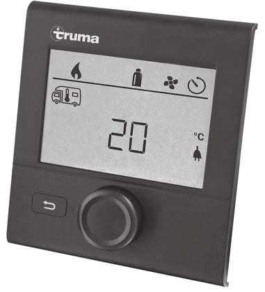
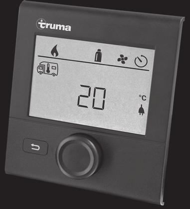
7 Examples of warm air distribution with Truma accessories It must be ensured that if a closable end outlet is being used (e.g. bathroom), at least one non-closable nozzle is installed in the warm air branch. If the warm air distribution or circulated air intake is partially or completely blocked, the VarioHeat switches off prematurely and full power is not available. VR 80 Installation Drill a Ø 10 mm hole. Feed the connector cable through the hole from behind and connect the end of the cable to the sensor with an insulated connection plug (polarity is unimportant). Insert the room temperature sensor and lay the cable end with bushing X7 to the heater (if necessary, extend to a maximum length of 10 m with x 0.5 mm² cables) cm SCW Plug the room temperature sensor on to the cable harness of the heater (refer to Electrical connections heater page 8). Fig Truma Warm air basic kit VR 80 Y 80 ÜR EN-0 X7 EM LA cm ÜR EN Fig mm Fig. 15- Truma Warm air basic kit + Warm air additional kit 3. Secure all pipe connections with clips / tapping screws. Fix pipes with ZRS / ÜS clamps. Circulated air intake The circulated air (U) is sucked in again by the heater. This must take place from the living room (not the rear storage locker) to the installation space via one large or several smaller openings with an overall area of at least 150 cm². Circulated air intake with grid If a grid (not supplied) is installed, the same requirements regarding the cross section through which the air is sucked in (150 cm²) must be observed. Installing a digital control panel Description Digital Truma CP plus VarioHeat control panel to operate a VarioHeat heater. A Truma Aventa comfort (from serial number /013) or Saphir comfort RC air conditioning system may also be connected. The control panel (with polarity protection) is supplied with power via a 1 V connector cable. The control panel is connected with a VarioHeat heater and / or air conditioning system with a connector cable (TIN Bus). Dimensions 9 9 W U U 103 Fig. 16 Example of circulated air intake through a grid Installing the room temperature sensor The supplied room temperature sensor must always be connected, otherwise the heater will indicate an error. Choosing a location When choosing a location, remember that the room temperature sensor must not be exposed to direct heat radiation. For optimum room temperature control, we recommend that you install the room temperature sensor above the entrance doors. Make sure that the sensor is always installed on a vertical wall. The room air must be allowed to flow around it freely Fig. 18 Dimensions in mm. Picture not to scale
8 Choosing a location Install the control panel in a place that is protected from moisture and wetness. So that it is easy to read the characters, install the control panel at eye height. Making the installation opening Installation Fix the frame to the wall with 4 screws. Fig. 1 View from the front + - Ø max. 3.4 mm ±1 Hook the control panel upper part into the frame with catches. Fix the control panel upper part with a screw. Slide the rotary push button on to the shaft. 3.5 Fig. 19 Dimensions in mm. Picture not to scale Electrical connection Observe ESD regulations. Lay the connector cable of the TIN Bus and the 1 V supply voltage in loops with no tension. The control panel must project approx. 0 cm out of the installation opening with no tensile loading for the connector. Never pull the connector cable when it is connected to the control panel Lay the connector cable (TIN Bus) to the heater or air conditioning system and plug into the control panel. Connect the 1 V connector cable and connect to the unswitched 1 V operating voltage (permanent positive). The heater and control panel Truma CP plus VarioHeat must be connected to the same circuit. The positive cable must be protected with a 1 A fuse. Fig. Installing the control panel upper part and rotary push button Electrical connections heater Lay the connector cables so that they cannot chafe. Also use edge protection or leadthrough bushing on sharp edges, such as holes on metal walls. The connector cables must not be fixed to or touch metallic equipment surfaces, the exhaust duct or the warm air ducts. The electrical connection is made via an external cable harness. Take care with the connector cables so that they are not pulled out or squashed. TIN-Bus CI-BUS V + = red - = red/black Fig. 0 View from the rear 1 Only with variant Truma CP plus VarioHeat CI-BUS. By default, an external control panel (master) is connected. 8
9 Wiring diagram Power supply 1 V A Electric cables, switching and control devices for heaters must be arranged in the vehicle so that they function perfectly under normal operating conditions. All cables that lead outside must be laid so that they are protected against spray water at the hole. Before starting work on electrical parts, you must disconnect the heater from the power supply. It is not sufficient to switch it off on the control panel! A To ensure an optimum power supply, the heater must be connected to the fused on-board power supply (central electricity system 10 A) with x.5 mm² cables (for lengths in excess of 6 m, with x 4 mm² cables). Potential drops in the supply line may have to be considered. Connect the negative cable to the central earthing system. If parts are connected directly to the battery, the positive and negative cables must be fused. No other equipment may be connected to the supply cable. In case of voltage reversal, fuse F1 is triggered. 1 X5 If connected to a battery. If connected to a power supply unit with at least 5 A. A X6 X7 If grid or power supply equipment is used, they must supply a controlled output voltage between 11 V and 15 V (AC voltage ripple < 1. Vpp). Battery connection Fig. 3 Wiring diagram Crimp 6.3 x 0.8 mm flat connectors* on to the positive and negative cables. X5 section B * The supplied flat connectors are suitable for cable crosssections from 0.8 to.5 mm. Use suitable flat connectors for other cable sizes. Insert the positive and negative cables in the plug X5 (contact 1 / ). B X6 Room temperature sensor connection Connect bushing X7 of the room temperature sensor to the X7 plug of the cable harness. A X7 Digital control panel connection Connect the X6 connector. Window switch connection (optional) Fig. 4 Cable harness Plug / contact Description section A X7-1 Room temperature sensor X7- Room temperature sensor X7-3 Window switch or wire bridge X7-4 Window switch or wire bridge X7-5 X7-6 X5-1 + Battery X5- - Battery X6 TIN Bus / Truma CP plus VarioHeat Separate the wire bridge (contact 3 / 4) in the X7 bushing. Cut off the two plug contacts from the cable of the window switch and connect with contact 3 / 4. Polarity is unimportant. 9
10 Gas connection The gas system must accord with the technical and administrative provisions of the individual country of use (in Australia, AS/NZS LP Gas installations). The nominal gas system pressure must be.75 kpa. For gas pipe sizing refer to AS/NZS LP Gas installations. Install the gas piping so that the heater can be dismantled easily for servicing. In the gas piping, limit the number of separation points in rooms used by people to a technically necessary minimum Before you connect the gas piping to the Pre-pressure regulator VarioHeat, make sure that it is free of dirt, metal filings, etc. The gas connection fitting on the heater must not be shortened or bent. When you are tightening the connection, use a second wrench as a brace. Installing the VarioHeat pre-pressure regulator The VarioHeat pre-pressure regulator is adjusted in the factory. During operation, the pressure at the gas pressure test point (3) must be1.8. kpa. If the VarioHeat prepressure regulator cannot be installed to perform correctly, please contact Dometic Service Centre. The VarioHeat pre-pressure regulator must be installed to ensure safe operation of the VarioHeat. The VarioHeat pre-pressure regulator can be installed in any direction. Connect the VarioHeat pre-pressure regulator (1) to the gas inlet connection () in accordance with the installation regulations for olive screw connections (e.g. ISO ). When you are tightening the connection, use a second wrench as a brace. 1 Male SAE 5/16 inch (1/ inch - 0 UNF) 3 Functional check Always observe the operating instructions prior to starting! 1. Start the appliance. Check all functions of the heater in accordance with the operating instructions. If faults occurring during operation of the appliance, refer to Troubleshooting in the Operating instructions. If the heater cannot be adjusted to perform correctly, please contact Dometic Service Centre. 3. To test the warm air distribution, at maximum fan level, the measured duct static pressure must be within the heater specifications (see below). 4. Provide operating instructions to the vehicle owner. The year of initial operation must be marked on the type plate. The appliance is now ready for normal operation and use. Warning The installer or vehicle owner must attach the yellow sticker with the warning that is supplied with the device at a place in the vehicle that is visible for every user (e.g. on the wardrobe door). More stickers can be obtained from Truma. Technical changes reserved. Heater specifications Type of gas Propane Test point pressure.00 kpa (see type plate) Operating pressure.75 kpa (see type plate) Rated thermal input (gas consumption) Min. stage: 4.53 MJ/h (90 g/h) ISA Max. stage: 9.75 MJ/h (193 g/h) ISA Thermal efficiency Min. stage: 86.4% Max. stage: 84.3% Air flow rate 85 m³/h m³/h Duct static pressure < 170 Pa (1.7 mbar) Temperature rise < 80 C Power supply V Power consumption at nominal Voltage 1 V Operating: A Stand-by: A Weight Heater without periphery: 5.5 kg Subject to technical changes. Fig. 5 After installation, you must check gas supply line for leaks in accordance with the pressure drop method. Do not use matches, candles or other sources of ignition when checking for gas leaks. 10
11
12 In Australia, always notify the Dometic Service Centre if problems are encountered; in other countries the relevant service partners should be contacted ( Having the equipment model and the serial number ready (see type plate) will speed up processing /017 Dometic Pty Ltd Building 3B, Clayton Business Park 1508 Centre Road Clayton, Victoria, 3168 Australia Service (Australia) Telephone: Facsimile: +61 (0)
Truma VarioHeat eco AU. Installation instructions Page 2
 Truma VarioHeat eco AU Installation instructions Page 1 3 4 Installation example Fig. 1 9 7 8 6 5 1 Room temperature sensor Control panel Truma CP plus VarioHeat 3 Electric window switch (optional) 4 Exhaust
Truma Combi D 6 AU. Installation instructions Page 2
 Truma Combi D 6 AU Installation instructions Page 2 Truma Combi D 6 AU 2 1 3 6 4 5 Fig. 1 Installation example 1 Control panel 2 Room temperature sensor 3 Circulated air intake (min.150 cm²) 4 Warm air
Truma VarioHeat eco AU. Operating instructions Page 2. To be kept in the vehicle!
 Truma VarioHeat eco AU Operating instructions Page 2 To be kept in the vehicle! Truma VarioHeat eco AU Inhaltsverzeichnis Trademark information... 2 Symbols used... 2 Intended use... 2 Prohibited use...
Trumatic E. Trumatic E 2400 (Australia) Operating instructions Page 4 Installation instructions Page 7. To be kept in the vehicle!
 Operating instructions Page 4 Installation instructions Page 7. To be kept in the vehicle!") Trumatic E 7 7 2 9 9 4 Trumatic E 2400 (Australia) Operating instructions Page 4 Installation instructions Page 7 To be kept in the vehicle! Trumatic E 2400 (Australia) Table of contents Installation example...
Trumatic E 7 7 2 9 9 4 Trumatic E 2400 (Australia) Operating instructions Page 4 Installation instructions Page 7 To be kept in the vehicle! Trumatic E 2400 (Australia) Table of contents Installation example...
Combi 2 E / 4 E CP plus (Australia) Operating instructions Page 2. To be kept in the vehicle!
 Operating instructions Page 2. To be kept in the vehicle!") Combi 2 E / 4 E CP plus (Australia) Operating instructions Page 2 To be kept in the vehicle! Combi 2 E / 4 E CP plus (Australia) 4 5 1 2 6 10 13 15 16 12 8 10 14 6 1 Control panel (digital) 2 Room temperature
Combi 2 E / 4 E CP plus (Australia) Operating instructions Page 2 To be kept in the vehicle! Combi 2 E / 4 E CP plus (Australia) 4 5 1 2 6 10 13 15 16 12 8 10 14 6 1 Control panel (digital) 2 Room temperature
Truma UltraRapid Hot Water System
 Truma UltraRapid Hot Water System LPG and 230 V / 240 V Electric Storage Water Heater Operating instructions Page 4 Installation instructions Page 8 To be kept in the vehicle! BGA 14 / BGEA 14 LPG (Propane)
Truma UltraRapid Hot Water System
 Truma UltraRapid Hot Water System LPG and 230 V / 240 V Electric Storage Water Heater Operating instructions Page 4 Installation instructions Page 8 To be kept in the vehicle! BGA 14 / BGEA 14 LPG (Propane)
Installation Manual. For Australian refrigerator models: N304M.3 (93 liter 3-way operation with LP gas, 240 volts AC, or 12 volts DC )
") Installation Manual For Australian refrigerator models: N304M.3 (93 liter 3-way operation with LP gas, 240 volts AC, or 12 volts DC ) N404M.3 (128 liter 3-way operation with LP gas, 240 volts AC, or 12
Installation Manual For Australian refrigerator models: N304M.3 (93 liter 3-way operation with LP gas, 240 volts AC, or 12 volts DC ) N404M.3 (128 liter 3-way operation with LP gas, 240 volts AC, or 12
Saphir comfort RC (Australia) Operating instructions Page 2 Installation instructions Page 9. To be kept in the vehicle!
 Operating instructions Page 2 Installation instructions Page 9. To be kept in the vehicle!") Saphir comfort RC (Australia) Operating instructions Page 2 Installation instructions Page 9 To be kept in the vehicle! Saphir comfort RC air conditioning system 3b 3b 5 4 3b Fig. 2 Fig. 1 3a 1 2b 2a Installation
Saphir comfort RC (Australia) Operating instructions Page 2 Installation instructions Page 9 To be kept in the vehicle! Saphir comfort RC air conditioning system 3b 3b 5 4 3b Fig. 2 Fig. 1 3a 1 2b 2a Installation
Boiler. L. P. Gas and 230/240 V Electric Storage Water Heater Model B 10 / B 14 from 11/2003
 Boiler L. P. Gas and 230/240 V Electric Storage Water Heater Model B 10 / B 14 from 11/2003 Boiler 60 70 230 V ~ Boiler EL Operating instructions Page 3 Installation instructions Page 6 To be kept in the
HYDRONIC II Technical description, installation, operating and maintenance instructions.
 HYDRONIC II Technical description, installation, operating and maintenance instructions. Heater for petrol Order No. Hydronic II B 4 S 12 V 20 1909 05 00 00 B 5 S 12 V 20 1904 05 00 00 Heater for diesel
Installation Requirements for Models:
 900 & 9100 Series Refrigerators Installation Requirements for Models: 9162 9163 9182 9183 962 963 982 983 WARNING Improper installation, adjustment, alteration, service, or maintenance can cause injury
OP44-1 REV 2: Removed depiction of air intake hole in the CB-907A Right Aft Case Baffle.
 REVISION DESCRIPTION: OP44-1 REV 2: Removed depiction of air intake hole in the CB-907A Right Aft Case Baffle. OP44-4 REV 1: Steps rewritten to describe the air intake hole on the CB-907A Right Aft Case
BR342 Ducted Installation Instructions Australian Version Electronic Wall Control
 Australian Version Electronic Wall Control 1 Introduction The BR342 reverse cycle rooftop air-conditioner is designed for installation onto Recreational Vehicles (RV s) at the time of manufacture or as
Truma AquaGo LP Gas Instant Water Heater
 Truma AquaGo LP Gas Instant Water Heater Model: Truma AquaGo basic (DLE6AB) * Truma AquaGo comfort (DLE6AC) * Truma AquaGo comfort plus (DLE6ACP) * * Patent Pending Operating instructions Page 2 Installation
User Manual. 600mm, 700mm & 900mm Gas Cooktops Model No. CF6GS, CF6GW, CF7GS, CF9GS
 User Manual 600mm, 700mm & 900mm Gas Cooktops Model No. CF6GS, CF6GW, CF7GS, CF9GS For all product enquires, including warranty support, please contact our Customer Care team 1800 444 357 or email customercare@hapl.com.au
CARVER CASCADE 2 & CASCADE 2 GE CARAVAN WATER HEATER INSTALLATION INSTRUCTIONS LEAVE THESE INSTRUCTIONS WITH THE USER
 CARVER - CASCADE 2 & CASCADE 2 GE CARAVAN WATER HEATER INSTALLATION INSTRUCTIONS LEAVE THESE INSTRUCTIONS WITH THE USER 1:0 SPECIFICATIONS Water capacity Water connections Water supply 9 litres (2 gallons)
BlueHeat AirTop 2000 Heater
 BlueHeat AirTop 000 Heater Air Heater Installation Manual Ford E-Series 6.0L Diesel Beginning Model Year: 006 Special instructions for these models Part locations may differ slightly dependent on the vehicle
Installer manual AG-AA10. Air/air heat pump IHB GB AG-AA10-30 AG-AA10-40/50
 -30 Installer manual Air/air heat pump -40/50 IHB GB 1516-1 331554 Table of Contents 1 Important information 2 5 Installation 7 Safety information 2 Model combinations 7 Read before starting the installation
INSTALLATION INSTRUCTIONS UNDERCOUNTER DISHWASHERS
 INSTALLATION INSTRUCTIONS UNDERCOUNTER DISHWASHERS VIKING 111 Front Street Greenwood, Mississippi 38930 USA (662) 455-1200 IMPORTANT - PLEASE READ AND FOLLOW Before beginning - please read these instructions
INSTALLATION MANUAL Power Flued Flamefire Space Heater Co-axial Flue System
 INSTALLATION MANUAL Power Flued Flamefire Space Heater Co-axial Flue System To Suit Power Flued Flamefire Models: RHFE-750ETR - ASPIRATION RHFE-752ETR RHFE-950ETR This appliance shall be installed in accordance
Boiler L. P. Gas and 230 / 240 V Electric Storage Water Heater Model B 10 / B 14 from 08/2008
 Boiler L. P. Gas and 230 / 240 V Electric Storage Water Heater Model B 10 / B 14 from 08/2008 Operating instructions Page 2 Installation instructions Page 6 To be kept in the vehicle! Comfort on the move
GAS COOKTOPS INSTALLATION INSTRUCTIONS. Model numbers ICBCG15 ICBCG304 ICBCG365
 GAS COOKTOPS INSTALLATION INSTRUCTIONS Model numbers ICBCG15 ICBCG304 ICBCG365 This cooktop is approved for use with Natural Gas & Propane Gas. Leave instructions with the owner. CONTACT INFORMATION Sub-Zero
Installation Instructions. For the 18 Built-In Dishwasher and Front Color Panels
 Installation Instructions For the 18 Built-In Dishwasher and Front Color Panels Printed in USA 154232102 Before You Begin DO NOT INSTALL DISHWASHER UNTIL YOU HAVE READ ALL INSTRUCTIONS. FOR YOUR SAFETY,
U tube models PTU 09, 12, 15, 25, 30, 35, 40, 45. single linear tube models PTS 09, 12, 15, 25, 30, 35, 40, 45
 U tube models PTU 09, 2, 5, 25, 30, 35, 40, 45 & single linear tube models PTS 09, 2, 5, 25, 30, 35, 40, 45 installation, servicing & operating instructions INSTALLATION, SERVICING AND OPERATING INSTRUCTIONS
COMMERCIAL GAS AND ELECTRIC STACKED WASHER/ DRYER INSTALLATION INSTRUCTIONS
 COMMERCIAL GAS AND ELECTRIC STACKED WASHER/ DRYER INSTALLATION INSTRUCTIONS MODELS MLG19PD, MLE19PD The installation, including a proper exhaust system, is the responsibility of the owner. LEAVE THESE
SIME FORMAT WALL HUNG BOILERS MODEL 34i AND MODEL 34e. cod A
 cod. 6272262A GENERAL DATA Heating Data Heat Output Input (Adjustable) (Adjustable) Format 34i 11.2 34KW 45 145MJ/hr Format 34e 11.2 34KW 45 145MJ/hr General Specifications FORMAT 34i 34e Main burner injectors
SEA FROST BD 12 OR 24-VOLT D.C. AIR-COOLED SYSTEM
 148 OLD CONCORD TURNPIKE BARRINGTON, NH 03825 USA TEL (603) 868-5720 FAX (603) 868-1040 1-800-435-6708 E-Mail:sales@seafrost.com www.seafrost.com SEA FROST BD 12 OR 24-VOLT D.C. AIR-COOLED SYSTEM CONDENSING
Camaro A/C Install Instructions
 1967-1968 Camaro A/C Install Instructions This kit is designed for the 1967-1968 non A/C equipped Camaro. This kit can be used with or without Astro vents Step One Remove the following factory components:
JOHN DEERE GATOR HPX/XUV 2 PASSENGER HEATER INSTALLATION INSTRUCTIONS (p/n: 9PH20S30)
") P. 1 of 12 JOHN DEERE GATOR HPX/XUV 2 PASSENGER HEATER INSTALLATION INSTRUCTIONS (p/n: 9PH20S30) Item: Qty: Description: 1 2 1 x 1 x 5/8 Tee Fitting 2 2 Plastic Snap-in Hose Grommet 3 4 1-1/2" Hose Clamps
P. 1 of 12 JOHN DEERE GATOR HPX/XUV 2 PASSENGER HEATER INSTALLATION INSTRUCTIONS (p/n: 9PH20S30) Item: Qty: Description: 1 2 1 x 1 x 5/8 Tee Fitting 2 2 Plastic Snap-in Hose Grommet 3 4 1-1/2" Hose Clamps
Chapter 3 Cooling, heating and ventilation systems
 3 1 Chapter 3 Cooling, heating and ventilation systems Contents Antifreeze mixture..............................see Chapter 1 Cooling fan assembly - testing, removal and refitting.............8 Cooling
INSTALLATION INSTRUCTIONS
 INSTALLATION INSTRUCTIONS DishDrawer TM dishwasher DD24SUT7 and DD24SVT7 models US CA 590225B 04.4 SAFETY AND WARNINGS Electrical hazard WARNING! Before installing the dishwasher, remove the house fuse
INSTALLATION INSTRUCTIONS
 INSTALLATION INSTRUCTIONS TM DishDrawer dishwasher DD36SDFTX (Designer) & DD36STI (Integrated) models US CA 59008D 04.3 a SAFETY AND WARNINGS Electrical hazard WARNING! Before installing the dishwasher,
Roof Top Unit. Description Model Type Use With Air Distribution Box Model B CX51R B CX51R
 RECORD THIS UNIT INFORMATION FOR FUTURE REFERENCE: Type Number Product Number Serial Number ADB Number ADB Serial Number Date Purchased Roof Top Unit Description Model Type Use With Air Distribution Box
Installation Instructions
 Installation Instructions For the 18" Built-In Dishwasher Sears, Roebuck and Co. Sears Canada, Inc. Hoffman Estates, IL 60179 U.S.A. Toronto, Ontario, Canada M5B 2B8 154435201 Before You Begin DO NOT INSTALL
INSTALLATION INSTRUCTIONS FOR. 230/240 VAC, 1ø, 50Hz 473X3 SERIES RV ROOF TOP AIR CONDITIONER
 INSTALLATION INSTRUCTIONS FOR 230/240 VAC, 1ø, 50Hz 473X3 SERIES RV ROOF TOP AIR CONDITIONER Service Contact: Coast to Coast RV Services Pty Ltd. PO BOX 415 REGENTS PARK DC NSW 2143 Australia Tel: +61-2-9645
Heater with Air Conditioning. E-Series Ford Aeromaster
 Service Guide Heater with Air Conditioning E-Series Ford Aeromaster Contents Blower Motor...2 Plenum Removal...3 Control Module...6 Servo Motors...8 Coolant Valve and Servo Motor...8 Evaporator Recirculation
Pizza Oven with Stand
 Pizza Oven with Stand Cooks up to 3 pizzas at a time Use to cook a variety of food Easy clean vitreous enamel interior Model No. P0104 Powerful 22MJ/h stainless steel burner Viewing window and temperature
INSTALLATION GUIDE NZ AU D
 GAS COOKTOP CG905DW models INSTALLATION GUIDE NZ AU 590684D 08.17 1 SAFETY AND WARNINGS! WARNING! Electrical Shock Hazard Before carrying out any work on the electrical section of the appliance, it must
Instructions for use. Gas hobs for installation in worktops GKS GWS GKS GKS
 Instructions for use Gas hobs for installation in worktops GKS 3920.0 GWS 3911.0 GKS 6940.0 GKS 9951.0 For use in: Hong Kong Issue: 2014-01-14 Version: 1.3_EN Identity no.: 073587_HK Welcome 2 Welcome
SINGLE DISHDRAWER TM DISHWASHER
 SINGLE DISHDRAWER TM DISHWASHER DD4SA & DD4SCT models INSTALLATION GUIDE US CA 595B 08.7 SAFETY AND WARNINGS! WARNING! Electrical Shock Hazard Before installing the dishwasher, remove the house fuse or
DOUBLE DISHDRAWER TM DISHWASHER
 DOUBLE DISHDRAWER TM DISHWASHER DD60DA & DD60DC models INSTALLATION GUIDE NZ AU GB IE 591151C 08.17 WARNING! Electrical shock hazard Before installing the dishwasher, remove the house fuse or open the
COMMERCIAL STACKED GAS DRYER/WASHER
 COMMERCIAL STACKED GAS DRYER/WASHER MODEL NO. CGT8000XQ0 c 2012 WHIRLPOOL CORPORATION 5 12 Litho In U.S.A. (CMS) (bay) Part No. Rev. H CONTROL PANEL PARTS 2 CONTROL PANEL PARTS 1 Literature Parts W10335467
DOUBLE DISHDRAWER TM DISHWASHER
 DOUBLE DISHDRAWER TM DISHWASHER DD4DDFT & DD4DVT models INSTALLATION GUIDE US CA 5985 A 08.7 SAFETY AND WARNINGS! WARNING! Electrical Shock Hazard Before installing the dishwasher, remove the house fuse
PERFECT FIT IN-DASH HEAT/ COOL/ DEFROST FORD PICKUP
 specializing in AIR CONDITIONING, PARTS AND SYSTEMS for your classic vehicle PERFECT FIT IN-DASH HEAT/ COOL/ DEFROST 1960-66 FORD PICKUP CONTROL & OPERATING INSTRUCTIONS The controls on your new Perfect
Service Instructions
 BASIC EXCELLENT PERFECT U Universal ovens I Incubators S Sterilisers Service Instructions Mo Tu We Th Fr Sa Su t3 on off h t2 t1 t4 loop 4 3 2 1 STERI DEFRO C MIN MAX C IN 1 IN 2 OUT IN 1 IN 2 OUT % rh
Installation Instructions
 PAGE 1 Installation Instructions Important information about your new a/c system. Please read the following directions prior to installing this a/c system. PN: CK6772-1CHPU 1967-1972 Chevy PU A/C Kit Contact
INSTALLATION INSTRUCTIONS
 INSTALLATION INSTRUCTIONS Gas Cooktop CG905DW models NZ AU www.fisherpaykel.com 590684B 11.14 1 Safety and warnings! WARNING! Electrical Shock Hazard Before carrying out any work on the electrical section
Installation Instructions
 GE Consumer & Industrial Appliances Installation Instructions Junction Box Cover Within this user bag, you will find a junction box cover and a #10 hex head screw used to attach the junction box cover
Installation GUIDE VDWU524SS VDWU524WSSS FDWU524WS FDWU524 VDWU324SS FDWU324
 Installation GUIDE VDWU524SS VDWU524WSSS FDWU524WS FDWU524 VDWU324SS FDWU324 To prevent accidents, which could cause serious injury or death, as well as machine damage read these instructions before installation
FRANKE DESIGNER GAS COOKTOP 90CM
 page 1 of 7 510 880 45 480 Min 50 860 Min 600 SPECIFICATIONS Recommended use Material Colour availability Weight Dimensions Voltage Domestic Stainless Steel Stainless Steel 18.2kg 880 x 510 x 45mm 220-240V
INSTALLATION, OPERATION, AND MAINTENANCE MANUAL
 INSTALLATION, OPERATION, AND MAINTENANCE MANUAL TUBE AXIAL FANS BTA, WTA, HTA, DDA The purpose of this manual is to aid in the proper installation and operation of the fans. These instructions are intended
Energysaver Space Heater Co-Axial Flue System Installation Manual
 Energysaver Space Heater Co-Axial Flue System Installation Manual To Suit Models: RHFE-308FTR RHFE-309FT RHFE-556FTR RHFE-556FDT RHFE-557FTR RHFE-559FT RHFE-561FT RHFE-1004FTR RHFE-1004FDT These components
AirUnit. Installation instructions. mfh systems modern floor heating. Decentralised domestic ventilation
 mfh systems modern floor heating AirUnit Decentralised domestic ventilation Installation instructions List of contents, Installation instructions Page 1. General information... 03 2. Function / planning
Service Manual For model N260 - a 2.4 cu. ft., 2-way refrigerator. For model N a 2.4 cu. ft., 3-way refrigerator.
 Service Manual For model N260 - a 2.4 cu. ft., 2-way refrigerator. For model N260.3 - a 2.4 cu. ft., 3-way refrigerator. NORCOLD, Inc. P.O. Box 4248 Sidney, OH 45365-4248 Part No. 619260A (4-98) Table
Installation and maintenance instructions
 6304 4994 03/2006 GB For installer Installation and maintenance instructions Flue gas heat exchanger WT30/40 Please read thoroughly prior to installation and maintenance. Contents Contents Contents 2 1
Calaer Marine add-on kit manual. 2kW Calaer air heater 4kW Calaer air heater
 Calaer Marine add-on kit manual 2kW Calaer air heater 4kW Calaer air heater 1. Introduction and scope 1. Introduction and scope The Calaer marine add-on kit is designed to be used with the Calaer air
SOUND-INSULATED FAN. Iso-K OPERATION MANUAL. Iso-K_v.1(2)-EN.indd :20:59
-EN.indd :20:59") SOUND-INSULATED FAN OPERATION MANUAL _v.1(2)-en.indd 1 10.08.2015 15:20:59 CONTENT Introduction 3 General 3 Safety rules 3 Transport and storage requirements 3 Manufacturer's warranty 3 Fan design 4 Delivery
SOUND-INSULATED FAN OPERATION MANUAL _v.1(2)-en.indd 1 10.08.2015 15:20:59 CONTENT Introduction 3 General 3 Safety rules 3 Transport and storage requirements 3 Manufacturer's warranty 3 Fan design 4 Delivery
INSTALLATION GUIDE NZ AU
 DISHWASHER DW60U6I & DW60U2I models INSTALLATION GUIDE NZ AU 1 SAFETY AND WARNINGS 100 lb 45 kg! WARNING! Electrical shock hazard Before installing the dishwasher, remove the house fuse or open the circuit
Pellet Stove. Flex Pipe. Appliance Connector
 Installation Instructions & Owners Maintenance Guide DT-M Direct-Temp for Multi Fuel L-Vent / Vent System for Pellet, Corn and other Bio-Fuel Burning Appliances Introduction Direct-Temp for Multi-Fuel
AGA TOTAL CONTROL. Model No s: TC3 & TC5 (ROOM VENT OPTION)
") AGA TOTAL CONTROL Model No s: TC3 & TC5 (ROOM VENT OPTION) Installation Guide REMEMBER: when replacing a part on this appliance, use only spare parts that you can be assured conform to the safety and performance
AGA TOTAL CONTROL Model No s: TC3 & TC5 (ROOM VENT OPTION) Installation Guide REMEMBER: when replacing a part on this appliance, use only spare parts that you can be assured conform to the safety and performance
Installation Instructions Part No , Part No Part No
 Torsion-Flex Motor mount for PSC motors and Rigid-Mount for ECM motors Replacement Kit Cancels: New Installation Instructions Part No. 327752-401, Part No. 327753-401 Part No. 327754-401 IIK-310A-45-11
INSTALLATION INSTRUCTIONS
 INSTALLATION INSTRUCTIONS TM DishDrawer dishwasher DD4S 7 & DD4ST 7 models US CA 59004D 04.3 FOLLOW THE INSTALLATION SEQUENCE RELEVANT TO YOUR MODEL STANDARD HEIGHT SINGLE MODELS TALL HEIGHT SINGLE MODELS
Combi D 6 (Australia)
") Combi D 6 (Australia) Operating instructions Page 2 To be kept in the vehicle! Combi 9 7 4 3 5 5 2 3 1 1 60 60 Comfort on the move Combi D 6 (Australia) 1 2 3 5 6 13 12 14 7 11 9 10 1 Control panel 2 Time
Combi D 6 (Australia) Operating instructions Page 2 To be kept in the vehicle! Combi 9 7 4 3 5 5 2 3 1 1 60 60 Comfort on the move Combi D 6 (Australia) 1 2 3 5 6 13 12 14 7 11 9 10 1 Control panel 2 Time
VIESMANN. Installation instructions VITOCELL 300-B. for contractors. Vitocell 300-B Type EVBA-A. Dual mode DHW cylinder, 300 and 500 l
 Installation instructions for contractors VIESMANN Vitocell 300-B Type EVBA-A Dual mode DHW cylinder, 300 and 500 l VITOCELL 300-B 1/2017 Dispose after installation. Safety instructions Please follow these
IMPORTANT SAFETY INSTRUCTIONS DANGER: WARNING:
 IMPORTANT SAFETY INSTRUCTIONS YOUR SAFETY AND THAT OF OTHERS IS PARAMOUNT This manual and the appliance itself provide important safety warnings, to be read and observed at all times. This is the attention
INSTALLATION INSTRUCTIONS
 INSTALLATION INSTRUCTIONS TM DishDrawer dishwasher DD4D 7 & DD4DT 7 models US CA 59004D 04.3 FOLLOW THE INSTALLATION SEQUENCE RELEVANT TO YOUR MODEL STANDARD HEIGHT DOUBLE MODELS TALL HEIGHT DOUBLE MODELS
INSTALLATION INSTRUCTIONS
 INSTALLATION INSTRUCTIONS TM DishDrawer dishwasher DD90SDF(H)TX, DD90SDFTM (Designer) & DD90S(H)TI (Integrated) models NZ AU GB IE 5900D 04.3 FOLLOW THE INSTALLATION SEQUENCE RELEVANT TO YOUR MODEL Designer
Gas and Electric Dryer user manual
 DV48H7400E(G)* DV45H7400E(G)* DV45H7200E(G)* DV45H7000E(G)* Gas and Electric Dryer user manual This manual is made with 100% recycled paper. imagine the possibilities Thank you for purchasing this Samsung
FLANGED CORR/GUARD CORR/GUARD INSTALLATION INSTRUCTIONS
 CORR/GUARD INSTALLATION INSTRUCTIONS This symbol on the nameplate means this product is listed by Underwriters Laboratories Inc. Tested to UL1738 / CAN / ULCS636-08 Listing No. MH26687 Testing No. 11EN
Table Top Patio Heater
 Table Top Patio Heater INSTRUCTION MANUAL MODEL: HPS-B Certified by international recognized standards. The infra-red with heat wave outdoor heater. Variable control gas valve with electric push igniter.
51AKS I S O OWNER S MANUAL
 LLOYD'S REGISTER QUALITY ASSURANCE 51AKS I S O 9 00 1 OWNER S MANUAL This manual applies to the following models Stand-alone Split 51AKS 085--- 51AKS 010--- 51AKS 185--- 51AKS 013--- 51AKS 113--- 51AKS
HR200WK Through the wall Heat Recovery Ventilator
 HR200WK Through the wall Heat Recovery Ventilator Installation and Maintenance Instructions Stock Ref No:- HR200WK 14120020 PLEASE READ INSTRUCTIONS IN CONJUNCTION WITH ILLUSTRATIONS. PLEASE SAVE THESE
OWNER S MANUAL. Portable Refrigerated Air Conditioner. CP12CW2 (English) (CP12CW2)
 (CP12CW2)") OWNER S MANUAL Portable Refrigerated Air Conditioner CP12CW2 (English) (CP12CW2) CONTENTS Introduction...1 Safety...2 Component location...3 Installation...4 Control and Display panel...5 Remote control...6
OWNER S MANUAL Portable Refrigerated Air Conditioner CP12CW2 (English) (CP12CW2) CONTENTS Introduction...1 Safety...2 Component location...3 Installation...4 Control and Display panel...5 Remote control...6
Installation instructions
 Installation instructions Absorption Refrigerator for Recreation Vehicles RM 530 RM 5330 RM 5380 MBA /20 N AUS / NZ Type C40 / 0 82 2690-99 Table of Contents 0.0 Unpacking and transport.................................
UB1 AIR CONDITIONING UNIT INSTALLATION INSTRUCTIONS
 UB1 AIR CONDITIONING UNIT INSTALLATION INSTRUCTIONS INSTALLATION INSTRUCTIONS: Carefully read these instructions before installing your new air-conditioner. AUSTRALIAN AUTOMOTIVE AIR AL00500054E 1 Table
Questions? Call 800.GE.CARES ( ) or visit our Web site at: GEAppliances.com In Canada, call or visit
 or visit our Web site at: GEAppliances.com In Canada, call or visit") Installation Instructions Electric Dryer 01 Questions? Call 800.GE.CARES (800.432.2737) or visit our Web site at: GEAppliances.com In Canada, call 1.800.561.3344 or visit www.geappliances.ca BEFORE YOU
Installation Instructions Electric Dryer 01 Questions? Call 800.GE.CARES (800.432.2737) or visit our Web site at: GEAppliances.com In Canada, call 1.800.561.3344 or visit www.geappliances.ca BEFORE YOU
Flue Installation Manual
 Flue Installation Manual Rinnai FFSS (Stainless Steel) flue systems Rinnai FFSS (Stainless Steel) coaxial flue system, suitable for use with the following Rinnai internal continuous flow water heater models:
DURANGO 12V Heater HF
 DURANGO 12V Heater HF-100012 1 Product description 2 Operating principle 3 Mounting recommendations 4 Troubleshooting 3 Safety instructions Page 1 of 5 1 Product description The DURANGO heater consists
an ISO 9001:2008 Registered Company GOLL ST. - SAN ANTONIO, TX ph fax MINI SPACE SAVER HEAT /COOL
 an ISO 9001:2008 Registered Company 18865 GOLL ST. - SAN ANTONIO, TX. - 78266 - ph.210-654-7171 - fax 210-654-3113 MINI SPACE SAVER HEAT /COOL 01000-QUX-A 01000-VUX-A 900101-VUX-A REV C 3/5/14, MINI SPACE
INSTALLATION GUIDE NZ AU C
 DISHWASHER DW60 models INSTALLATION GUIDE NZ AU 591217C 12.17 1 SAFETY AND WARNINGS! WARNING! Electrical shock hazard Before installing the dishwasher, remove the house fuse or open the circuit breaker.
Operating and Installation Instructions for CRAMER COE Gas Cooker
 Operating and Installation Instructions for CRAMER COE Gas Cooker Models: COE-C COE-CG COE-CGO COE-FULL COE-C-DUFU COE-CG-DUFU COE-CGO-DUFU COE-FULL-DUFU Cooker (4 gas burners) Cooker + grill (4 gas burners)
51AKB / 51 AKC OWNER S MANUAL
 51AKB / 51 AKC OWNER S MANUAL This manual applies to the following models 51AKB 009 51AKB 012 51AKC 009 51AKC 012 Read this instruction manual thoroughly before using the air conditioner. Control panel
Installation Instructions Built-In Dishwasher
 GE Consumer & Industrial Appliances Installation Instructions Built-In Dishwasher If you have questions, call 800.GE.CARES (800.432.2737) or visit our website at: www.ge.com BEFORE YOU BEGIN Read these
INSTALLATION AND OPERATING INSTRUCTIONS I INSTALLATION AND OPERATING INSTRUCTIONS
 INSTALLATION AND OPERATING INSTRUCTIONS I INSTALLATION AND OPERATING INSTRUCTIONS AstralPool Coaxial Flue System Bolero ND Cleaner INSTALLATION AND OPERATING INSTRUCTIONS 75MM / 125MM DIAMETER TO SUIT
Installation Manual EF5000 AUS & NZ
 Installation Manual EF5000 AUS & NZ This manual is ONLY for fires with a serial No. from 80600 to 80999. Important: The appliance shall be installed in accordance with; Local gas fitting regulations Municipal
Installation Instructions
 40MBFQ Floor Console Ductless System Sizes 09 to 12 Installation Instructions TABLE OF CONTENTS PAGE SAFETY CONSIDERATIONS... 2 PARTS LIST... 3 SYSTEM REQUIREMENTS... 4 DIMENSIONS... 5 CLEARANCES... 5
Moisture inside the drum is due to final testing.
 Safety instructions Scope of delivery depending on model Moisture inside the drum is due to final testing. Removing the transport braces Water connection depending on model The washing machine is heavy
VERSAFLOW VORTEX Supplementary instructions
 VERSAFLOW VORTEX Supplementary instructions Vortex flowmeter Equipment category II 2G CONTENTS VERSAFLOW VORTEX 1 Safety instructions 3 1.1 General notes... 3 1.2 EC conformity... 3 1.3 Approval according
Contents. 1. Instructions for safety and use 20
 Contents 1. Instructions for safety and use 20 2. Positioning in the counter top 21 2.1 Fixing to the supporting structure 21 2.2 Positioning the adhesive sponge 22 2.3 Positioning the fastening clips
INSTALLATION INSTRUCTIONS
 INSTALLATION INSTRUCTIONS BUILT-IN BOTTOM MOUNT REFRIGERATOR/FREEZER DBRTGK72SS-GRILLE KIT (FOR designer SERIES ONLY) VIKING RANGE CORPORATION 111 Front Street Greenwood, Mississippi (MS) 38930 USA (662)
INSTALLATION AND OPERATING INSTRUCTIONS GN2. HIGH EFFICIENCY CAST IRON BOILER FOR LIQUID and/or GAS FUELS
 INSTALLATION AND OPERATING INSTRUCTIONS HIGH EFFICIENCY CAST IRON BOILER FOR LIQUID and/or GAS FUELS INDEX 1. Technical information... page 3 2. Dimensional and technical characteristics... page 3 3. Packing
Merloni Elettrodomestici. Technical Fitting Manual OVENS. Language Issue/Edition Page GB /
 GB 99-11-03/01 1-18 Index 1 WORKING AND FITTED DIMENSIONS 3 1.1 Oven size 60 cm 3 1.2 Maxioven 4 2 INSTALLING THE FITTED OVEN 5 3 FITTED GAS - INSTALLATION REQUIREMENTS 5 4 FIXING THE OVEN TO THE UNIT
PERFECT FIT SERIES IN-DASH HEAT/ COOL/ DEFROST CHEVROLET CHEVELLE/ EL CAMINO NOTE: INSTRUCTIONS DEPICT CHEVELLE
 specializing in AIR CONDITIONING, PARTS AND SYSTEMS for your classic vehicle PERFECT FIT SERIES IN-DASH HEAT/ COOL/ DEFROST 1964-65 CHEVROLET CHEVELLE/ EL CAMINO NOTE: INSTRUCTIONS DEPICT CHEVELLE CONTROL
Installation instructions
 instructions Absorption Refrigerator for Recreation Vehicles RM 530 RM 5330 RM 5380 MBA 0/0 N - AUS / NZ Type C40 / 0 8 690-99 Table of Contents 0.0 Unpacking and transport.................................
Service Manual Model 3163
 Service Manual Model 3163 Contents Important Safety Information.......... 1 Specifications.................. 2 General Information.............. 2 Direct Vent Requirements........... 2 Propane System................
INSTALLATION INSTRUCTIONS FOR 8330*5511 MOUNTING KIT
 RV Products Division INSTALLATION INSTRUCTIONS FOR 8330*5511 MOUNTING KIT 8330-752 CONTROL BOX KIT (12 VDC COOL ONLY) 9330A755 CONTROL BOX KIT (12 VDC HEAT/COOL) 8530-750 CONTROL BOX KIT (24 VAC COOL ONLY)
DISHWASHER. Models DW2432 and DW2432SS. Installation Manual. Write Serial Number (on inner door of unit) here:
 here:") DISHWASHER Models DW2432 and DW2432SS Installation Manual Write Serial Number (on inner door of unit) here: Felix Storch, Inc. Summit Appliance Division 770 Garrison Avenue Bronx, New York 10474 www.summitappliance.com
DISHWASHER Models DW2432 and DW2432SS Installation Manual Write Serial Number (on inner door of unit) here: Felix Storch, Inc. Summit Appliance Division 770 Garrison Avenue Bronx, New York 10474 www.summitappliance.com
Installation and maintenance instructions
 6304 4995 0/004 GB For installer Installation and maintenance instructions Flue gas heat exchanger WT50/60 Please read thoroughly prior to installation and maintenance. Summary About this manual This equipment
Fitting Instructions: Street Triple Rx, Daytona 675 from VIN and Daytona 675 R from VIN A
 English Fitting Instructions: Street Triple Rx, Daytona 675 from VIN 564948 and Daytona 675 R from VIN 564948 A9808114 Thank you for choosing this Triumph genuine accessory kit. This accessory kit is the