Guide For Proper Use Of Smoke Detectors In Duct Applications
|
|
|
- Geoffrey Todd
- 5 years ago
- Views:
Transcription
1 Guide For Proper Use Of Smoke Detectors In Duct Applications
2 GUIDE FOR PROPER USE OF SMOKE DETECTORS IN DUCT APPLICATIONS 1994 EDITION INDEX FOREWORD: PURPOSE PAGE 1. Glossary of Terms 1 2. Introduction 3 3. Characteristics of Smoke in HVAC Systems 6 4. Duct Smoke Detection Equipment 9 5. Typical Air Handling Systems How Duct Detection Systems are Used to Control Smoke Procedure for Duct Detector Application and Installation Maintenance and Service of Detectors for Use in Ducts 24
3 FOREWORD The purpose of this guide is to provide much needed information concerning the proper use of smoke detectors in duct applications. Duct mounted smoke detectors are designed to provide a specific type of protection that cannot be duplicated by any other type of system. However, there has been a tendency to misapply these devices in the past attempting to use them as a substitute for an early warning smoke detection system. This fact, coupled with new methods of detecting smoke in ducts, has prompted the writing of this industry guide. Fire Protection Engineers, Mechanical and Electrical Engineers, Fire Alarm System designers and installers should find the contents both educational and informative. This information is intended as a technical guide, as distinct from mandatory requirements.
4 SECTION 1 GLOSSARY OF TERMS 1.1 TERMS Air Sampling Detector: An extremely sensitive smoke detection device that can sample, test and evaluate the amount of particle concentration within an air sample Area Smoke Detector: A device that will detect visible or invisible particles of combustion. Also called a spot type detector Coil: A cooling or heating element made of pipe or tubing Coil, direct expansion: Coil using the direct refrigeration method CFM: Unit volume of flow cubic feet per minute Damper: A valve or plate regulating the flow of air or other fluid Damper, multiple louver: A damper having a number of adjustable blades, used to vary the volume of air passing through a confined section by varying the cross sectional area Duct: A passageway made of sheet metal or other suitable material not necessarily leak-tight, used for conveying air or other gas at low pressures Duct Smoke Detector: A device located within the duct, protruding into the duct, or located outside the duct that detects visible or invisible particles of combustion flowing within the duct. Actuation of the device may allow operation of certain control functions Exhaust Tube: Usually a round tube that provides a path for sampled air to return from the detection device to the duct Fan: An air moving device comprising a wheel or blade and a housing or orifice plate Humidifier: A device to add moisture to the air Inch of Water: A unit of pressure equal to the pressure exerted by a column of water at a temperature of 4.0 C (39.2 F). 1
5 Ionization Detector: A smoke detector using the principle of ion flow within a chamber to detect visible and invisible particles of combustion (within a size range normally encountered as a result of fire) Light Beam Detector: A smoke detection device that operates on the smoke obscuration principle Photoelectric Detector: A smoke detector using the principle of optical detection of visible particles of combustion Pitot Tube: A device used to measure the total pressure of a fluid stream. It is essentially a tube attached to a manometer at one end and pointed upstream at the other Pressure: The normal force exerted by a homogenous liquid or gas per unit of area on the wall of a container Pressure Differential: A pressure difference (usually specified in inches of water) between two points in a duct Return Exhaust: The duct which is used to return the air to the HVAC processing center for conditioning Sampling Tube: Usually a round tube with holes that collects air from the duct and brings it to the detection device Smoke Detectors: A device used to automatically sense the presence of particles of combustion Stratification: A phenomenon where smoke or other gases travel in layers at different levels within the duct, rather than being evenly distributed throughout the duct Supply Duct: The duct which distributes conditioned air, i.e., cooled, heated, cleaned, humidified, etc. 2
6 SECTION 2 INTRODUCTION 2.1. PURPOSE OF DUCT SMOKE DETECTION National and local safety standards and codes recognize the ability of air duct systems to transfer smoke, toxic gases, and flame from area to area. Sometimes smoke can be of such quantity as to be a serious hazard to life safety unless blowers are shut down and dampers are actuated. The primary purpose of duct smoke detection, then, is to prevent injury, panic, and property damage by reducing the spread (recirculation) of smoke. Duct smoke detection can also serve to protect the air conditioning system itself from fire and smoke damage, and can be used to assist in equipment protection applications, for example, in the ventilation/exhaust duct work of mainframe computers and tape drives APPLICATIONS NFPA 90A 1, Standard for the Installation of Air Conditioning and Ventilating Systems, specifies that "Smoke Detectors listed for use in air distribution systems shall be located: (a) (b) Downstream of the air filters and ahead of any branch connections in air supply systems of greater than 2,000 cfm (944 L / sec) capacity. At each story prior to the connection to a common return and prior to any recirculation or fresh air inlet connection in air return systems over 15,000 cfm (7080 L/sec) capacity, and serving more than one story. Exception No. 1: Return system smoke detectors are not required when the entire space served by the air distribution system is protected by a system of area smoke detectors. Exception No. 2: Fan units whose sole function is to remove air from inside the building to outside the building Perhaps more important is the identification of what duct smoke detection is not intended for rather than what it is. It is NOT a substitute for an area smoke detector. It is NOT a substitute for early warning detection. It is NOT a replacement for a building s regular fire detection system. 1 NFPA 90A, Section
7 NFPA 90A supports this by stating: Protection provided by the installation of smoke detectors and other related requirements is intended to prevent the distribution of smoke through the supply air duct system and, preferably, to exhaust a significant quantity of smoke to the outside. Neither function, however, will guarantee either early detection of fire or the detection of smoke concentrations prior to dangerous smoke conditions if smoke movement is other than through the supply air system NFPA 72 States: Detectors that are installed in the air duct system, shall not be used as a substitute for open area protection. Dilution of smoke-laden air by clean air from other parts of the building, or dilution by outside air intakes, may allow high densities of smoke in a single room with no appreciable smoke in the air duct at the detector location. Smoke may not be drawn from open areas when air conditioning or ventilating systems are shut down Area smoke detectors are the preferred means of controlling smoke spread since: Duct smoke detectors can only detect smoke when smoke laden air is circulating in the ductwork. Fans may not be running at all times, such as during cyclical operation or during temporary power failure Duct smoke detectors sample great volumes of air from large areas of coverage. They cannot be expected to match the detection ability of area detectors Dirt contaminated air filters can restrict air flow causing a reduction in the operating effectiveness of the duct smoke detectors APPLICABLE DOCUMENTS There are several important documents that provide guidance concerning the performance, application and installation of duct detectors: U.L. Standard 268A, Standard for Smoke Detectors for Duct Applications 1 NFPA 90A, Appendix A NFPA 72, Section
8 2.4. TYPICAL SCENARIOS NFPA Standard 90A-1989, Installation of Air Conditioning and Ventilating Systems NFPA Standard 92A-1988, Smoke Control Systems NFPA Standard 72E-1990, Automatic Fire Detectors NFPA Standard , Life Safety Codes ASHRAE Handbook and Product Directory, Chapter 38, Fire and Smoke Control Duct smoke detection may be useful in preventing injury and property damage in instances such as the following: A heating, ventilating, or air conditioning (HVAC) fan motor overheats and resulting smoke is sensed by the duct detector installed in the main supply duct. The duct detector is equipped with an auxiliary relay that immediately cuts power to the fan motor before significant amounts of smoke can be distributed to the occupied areas A fire start on the second floor of building. The HVAC system serving the second floor also serves floors one through four; therefore, smoke is being spread to these floors as well. If area smoke detectors are not provided the only means of automatic detection are the duct smoke detectors located in the return air ducts on each floor ahead of the main return plenum. The quantity of smoke in the duct eventually reaches proportions sufficient to alarm the second floor duct detector which transmits a signal to the building fire alarm system. Evacuation signaling and HVAC shutdown functions are then provided by the fire alarm control unit. Refer to Chapter 9 of NFPA 72E, and NFPA 92A for control of smoke spread. 5
9 3.1. GENERAL SECTION 3 CHARACTERISTICS OF SMOKE IN HVAC SYSTEMS Since the primary purpose for detecting smoke in the HVAC system is to automatically initiate action to minimize the spread of smoke through the air handling system, it follows that the nature of the smoke to be expected in various parts of the system should be understood. The following discussion is a theoretical description of smoke characteristics as they pertain to this application, as yet, not supported by fire test data SMOKE To begin with, smoke, as defined in NFPA 72, is the totality of the airborne visible or invisible particles of combustion. Smoke detectors are designed to sense the presence of particles, but depending upon the sensing technology and other design factors, different detectors respond to different types of particles. Detectors based on ionization detection technology are most responsive to the smaller, invisible submicron sized particles. Detectors based on light scattering technology, by contrast, are most responsive to the larger visible particles. Detectors based on light extinction technology respond to both visible and invisible particles. Figure 3-1 shows the relative sensitivity of the three technologies as a function of particle diameter, assuming a constant mass of particles C 2 RELATIVE SENSITIVITY A B PARTICLE DIAMETER µm B A C A - Scattered light principle (according to Bol) B - Extinction principle (according to Hosemann) C - Ionization chamber principle (according to Hosemann) Figure 3-1: Relative Sensitivities of Three Technologies as a Function of Particle Diameter (Source: NBS IR , Smoke Measurements In Large and Small Scale Fire Testing, by Richard W. Bukowski) 6
10 It is generally accepted that particle size distribution varies from sub-micron diameter particles predominant in the proximity of the flame of a flaming fire to particles one or more orders of magnitude larger, characteristic of smoke from a smoldering fire. The actual particle size distribution depends upon a host of other variables including the fuel and its physical makeup, the availability of oxygen including air supply and fire gas discharge, and other ambient conditions, especially humidity. Moreover, the particle size distribution is not constant, but as the fire gases cool, the sub-micron particles agglomerate and the very large ones precipitate. In other words, as smoke travels away from the fire source, the particle size distribution shows a relative decrease in smaller particles. Water vapor, which is abundantly present in most fires, when cooled sufficiently will condense to form fog particles an effect frequently seen above tall chimneys. Since water condensation is basically clear in color when mixed with other smoke particles, it can be expected to change the color of the mixture to a lighter one From the above discussion, one can begin to get an idea of what smoke is in the various parts of an air handling system. Specifically, the farther away the point of observation from the fire source, the cooler the smoke will be and the more visible because of the growth of sub-micron particles by agglomeration and recombination. There probably is some loss in quantity, i.e., the mass of the smoke particles at the point of entry to a duct system is probably greater than at some finite point downstream. However, at concentrations of concern, losses by precipitation are probably negligible CHANGE IN CONCENTRATION A much more important consideration is the change in concentration because of dilution by clean air from other return air ports in the duct system. A simple mathematical consideration will show that the original concentration is given by Q/V where Q is the quantity of smoke particles and V the volume in which they are dispersed. If a return duct has four branches, each with equal air flow (cfm), then after they join, the concentration will be reduced to Q/4V The preceding assumes uniform dispersion of particles which represents an ideal condition. In reality there is non-uniform dispersion and concentration can and does vary from no smoke to a very high concentration of smoke in a cross-section area of a duct. This is especially true just downstream from any point of entry. In a return air duct, for example, stratification can be expected immediately downstream from each return air grill. Text books teach that uniform dispersion is reasonably assured at a distance equal to 10 duct widths downstream for a duct with turbulent air flow. (In practical considerations, NFPA 72 accepts at least 6 duct widths, but the 10 duct width distance should be used when possible.) In those cases where laminar flow is predominant, uniform dispersion might never be achieved. 7
11 Air velocity has no direct effect upon the characteristics of smoke. It does affect the concentration because as velocity is increased, the total volume of smoke being produced and dispersed at some rate, {Q/dt} (the quantity of smoke per given time period), increases proportionately. Stated differently, in a one foot square duct an air velocity of one hundred feet per minute would transport one hundred cubic feet of air each minute. Increasing the velocity to four hundred feet per minute would increase the volume of air transported to four hundred cubic feet per minute, thereby reducing the concentration of smoke particles by a factor of four, assuming that the rate of smoke generation was the same in both cases. 8
12 4.1. DUCT SMOKE DETECTORS SECTION 4 DUCT SMOKE DETECTION EQUIPMENT Definition: A duct smoke detector is a device or group of devices used to detect the presence of smoke in the airstream of duct work sections of the HVAC air handling systems typically used in commercial buildings. (Paragraph 1.1.9) Typical smoke detection devices used for duct application include area smoke detectors within an enclosure mounted outside the duct utilizing sampling tubes (Figure 4-1), area smoke detectors listed for in-duct or partial in-duct mounting, a light beam detector consisting of projector and receiver mounted within the duct and an air sampling type detector. In all cases, alarm contacts are available either in the detector or in the fire alarm control unit to initiate air movement control or to perform other control functions An externally mounted duct detector enclosure may incorporate either an ionization or photoelectric type smoke detector. Air stream sampling is accomplished by sampling tubes that penetrate and traverse either the supply or return air ducts. The sampling tubes are positioned so air may be drawn through the detector, sampled, and then returned to the air stream in the duct. (Figure 4-2). FOAM GASKETS CONDUIT HOLES INLET SAMPLING TUBE (SUPPLIED SEPARATELY) DUCT DETECTOR HOUSING TUBE END PLUG PC BOARD INSULATOR O-RINGS DUCT DETECTOR COVER SAMPLING TUBE MOUNTING SCREWS DETECTOR BASE HOUSING MOUNTING SCREWS EXHAUST FILTER ADAPTER DETECTOR HEAD (SUPPLIED SEPARATELY) TEST MAGNET SAMPLING TUBE FILTERS Figure 4-1: Typical Duct Smoke Detector (Exploded View) 9
13 TUBE SUPPORT HOLE ONLY FOR DUCTS MORE THAN 3 FEET WIDE DUCT WIDTH AIR FLOW DIRECTION INSERT RUBBER PLUG THIS END OF INLET TUBE INLET TUBE HOLES FACE UPSTREAM OF AIR FLOW EXPECTED AIR FLOW DIRECTION RETURN TUBE SLANT CUT FACE ORIENTED DOWNSTREAM OF AIR FLOW DO NOT INSERT RUBBER PLUG Figure 4-2: Typical Installation Using Air Sampling Tubes An area smoke detector, listed for the application, may be mounted on an outlet box totally within the duct or they may be mounted on the exterior of the duct, with the sensing area of the detector protruding into the air stream. (Figure 4-2) Another duct detection device may be the light beam type detector. This unit performs best when utilizing long beam paths, e.g., in the large plenums rather than small ducts Air sampling detection units are relatively new. Extremely sensitive, they can detect minute changes in air particle concentration. An air sampling detection tube or head is inserted in the air stream of the duct. Air is drawn out and through the detection device. The detection unit typically is set at an operating level of normal background particle concentration. An alarm will sound when concentration exceeds a preset alarm threshold value. (Figure 4-3) EXHAUSTED AIR DETECTOR SAMPLING POINT (AIR DUCT FOR EXAMPLE) POWER SUPPLY CONTROLLER Figure 4-3: Typical Air Sampling Detector Installation 10
14 SECTION 5 TYPICAL AIR HANDLING SYSTEMS 5.1. GENERAL Heating, ventilating and air conditioning systems, as applied to commercial buildings, condition and distribute air usually through a network of ducts The air handling system can be divided into four basic segments. Figure 5-1 shows a simplified schematic view of a typical air handling system. EXHAUST AIR AIR RETURNING FROM CONDITIONING SPACE RETURN AIR COOLING COIL HEATING COIL DISCHARGE AIR TO TERMINAL SECTION OUTSIDE AIR F I L T E R SUPPLY FAN MIXED AIR SECTION CONDITIONING SECTION FAN SECTION TERMINAL SECTION HUMIDIFIER Figure 5-1: Typical Air Handling System 5.2. MIXED AIR SECTION This section consists of a plenum where recirculated (return) air and fresh (outside) air are introduced and mixed. A filter removes dirt, dust and other airborne particles from the air before it enters the conditioning section CONDITIONING SECTION The conditioning section generally consists of a heating coil, a cooling coil, a humidifier or any combination thereof. These coils may be arranged in series, in parallel or in a combination of series and parallel The cooling coil lowers the temperature of the air passing through either by using chilled water or direct expansion of a refrigerant gas supplied from a remote refrigeration compressor. 11
15 The heating coil raises the temperature of the air passing through it by means of steam, hot water, or electric heaters Humidifiers add moisture in the form of dry steam directly into the air stream. A humidifier is shut off whenever the system supply fan is not running to avoid moisture damage to the duct system FAN SECTION This section consists of one or more fans powered by a single electric motor. The fan section may be placed before or after the conditioning coils The fan section may include a device to regulate the static pressure developed by the fan. This device might be an inlet vane (vortex) damper, discharge damper, suction damper, or a device to regulate the fan speed. 5.5 TERMINAL SECTION This section controls the volume or the final conditioning of the air before it is supplied to the conditioned space. Sometimes terminal devices are located in the same mechanical equipment room that houses the air handler. More often, terminal devices are located remote from the individual spaces that they serve. These terminal devices can be reheat coils, mixing boxes, variable volume boxes and induction units KEY PARAMETERS The capacity of air handling systems are typically rated in cfm (cubic feet per minute). This is determined by multiplying the cross sectional area of the duct in square feet times the velocity of the air in feet per minute. (Note for a metric system the capacity is rated in cubic meters per second.) Air velocities used in duct systems are typically 500 ft/m (2.54 m/s) which is the rating for most of the heating and cooling coils used in the systems. Higher velocities may be encountered in applications where air must be moved through longer ducts. Maximum velocities encountered there can be as much as 4500 ft/min (22.9 m/s). The air velocity in the supply (fan discharge) side will be larger than in the return side. Velocities in the return side may be as low as ft/m ( m/s) The range of sizes in duct work varies greatly. The smaller ducts are similar in size to the air ducts used in a residential dwelling and may be less than 1 1 (.3 m.3 m). The maximum duct sizes used in large air handling systems are: 12
16 SYSTEM TYPE SUPPLY SIDE RETURN SIDE High Pressure 8 8 Can be very large, (2.78 m 2.78 m) (4.18 m 4.18 m) or more Low Pressure 6 (2.09 m) diameter The air pressure inside a duct with respect to the air pressure outside the duct is positive on the supply side of the fan and is negative on the return side. PRESSURE IN INCHES H 2 O (kpa)* SYSTEM TYPE SUPPLY SIDE RETURN SIDE Max In Typical Max In Typical High Pressure +5 (1.24) +4.0 (.99) 2 (.50) 1 (.25) Low Pressure +2 (.50) +1.5 (.37) 2 (.50) 1 (.25) *(1 H 2 O =.2486 kpa) The temperature inside the duct of an operating air handling system is between 42 F and 180 F (5.6 C and 82.2 C) Cooling applications have the lowest temperatures. For heating applications, the typical temperature is about 100 F (37.8 C). The 180 F (82.2 F) temperature is unusual and is encountered only in areas near a steam coil When the fan is off, temperatures in the vicinity of a steam coil may reach 240 F (115.6 C). A device located here may be even warmer due to radiation from the steam coil The temperature of the air in the mixed air and outside air sections are affected by the outdoor temperature. In very cold climates, the temperature in these sections can be as low as 40 F ( 40 C) The expected temperature range surrounding the duct system is: Indoor areas Outdoor areas 45 F to 120 F (7.2 C to 48.9 C) 40 to 160 ( 40 C to 71.1 C) 13
17 SECTION 6 HOW DUCT DETECTION SYSTEMS ARE USED TO CONTROL SMOKE 6.1. GENERAL An HVAC system supplies conditioned air to virtually every area of the building. Smoke introduced into this air duct system covers the entire building. Smoke detectors designed for use in air duct systems are used to sense presence of smoke in the duct NFPA 90A NFPA 90A, Standard for Air Conditioning and Ventilating Systems, requires that smoke detectors listed for duct installations be installed at a suitable location in the main supply duct on the downstream side of the filters to automatically stop the supply fans in systems over 2,000 cfm. For systems over 15,000 cfm additional detectors are required in the return system of each floor, at the point of entry into the common return, or a system of smoke detectors is required to provide total area coverage. (NOTE: Users of this manual should refer to NFPA 90A for more information on smoke control requirements.) 6.3. TYPICAL SINGLE ZONE HVAC SYSTEM Figure 6-1 shows a typical single zone HVAC system. DAMPERS DUCT SMOKE DETECTOR EXHAUST AIR DS OPTIONAL RETURN AIR FAN RETURN AIR TYPICAL FLOOR RETURN MIXED AIR DAMPER HEATING COIL OUTSIDE AIR MIXED AIR DAMPER SUPPLY FAN DS CONDITIONED AIR TO SPACE FILTER COOLING COIL HUMIDIFIER DUCT SMOKE DETECTOR Figure 6-1: Typical Single Zone System A return air fan is not used in all systems. Detectors may be placed in the outdoor air supply to sense if smoke is being drawn into the system from outside of the building. 14
18 It would then close the outdoor air damper allowing the rest of the HVAC system to continue operating In the typical fan system shown in Figure 6.1, when any duct smoke detector senses smoke, the fan system will be turned off and all the dampers shown will go to their closed positions. These actions are intended to prevent smoke from being distributed via the air handling system to unaffected areas of a building An alternate method that may be used is to only stop the supply fan and keep the return fan running. In this method the outdoor air damper and the mixed air damper go closed and the (exhaust) air damper is opened. This technique will help exhaust smoke-laden air from the building In addition to the requirements of NFPA 90A, duct smoke detectors may also be used within duct systems as detection devices in engineered smoke control systems. These systems are engineered for the specific building. They use the building construction and air handling systems to contain and reduce the spread of smoke NFPA 90A 1 requires that if there is an approved fire alarm system installed in a building the required duct smoke detectors be connected to the fire alarm system so that activation of any duct smoke detector will cause a supervisory signal to be indicated at a constantly attended location, or will cause an alarm signal TYPICAL FAN CONTROL CIRCUIT Figure 6-2 shows a typical fan control circuit. LINE SIDE L1 L2 L3 CONTACTOR LOAD SIDE H ON OFF N CONTACTOR AUXILIARY CONTACT DUCT SMOKE CONTROL DETECTOR CONTACT (OPENS WHEN SMOKE IS DETECTED) 1 NFPA Standard 90A, Section { OVERLOAD SAFETY COTROLS COIL CONTACTOR Figure 6-2: Typical Fan Control Shut Down Circuit 15
19 SECTION 7 PROCEDURE FOR DUCT DETECTOR APPLICATION AND INSTALLATION 7.1. APPLICATION Select supply and exhaust ducts to be monitored by smoke detectors Locate supply or exhaust input / output ports, filters, diluters, dampers, chillers, heaters, humidifiers, dehumidifiers, air cleaners, control devices, deflectors, bends and restrictors in engineering drawings and specifications Supply duct installation should be downstream of fans, filters, chillers, heaters, and humidifiers Duct detectors in the return air stream should be located at every return air opening within the smoke compartment, or where the air exits each smoke compartment, or in the duct system before air enters the return air system common to more than one compartment. Exception: Additional smoke detectors are not required in ducts where the air duct system passes through other smoke compartments not served by the duct Location of detectors mounted in or on air ducts should be between 6 and 10 duct widths downstream from any duct openings, deflection plates, sharp bends or branch connections Exception: Where it is physically impossible to locate the detector accordingly, the detector can be positioned closer than 6 duct widths, but as far as possible from the opening, bend or deflection plates Upon selection of location for duct detector installation, drill a hole into the duct and measure duct air velocity, humidity, and temperature. Refer to duct instrumentation for instrument use in this manual. (Page 20) Measure room temperature and humidity in the area of intended duct detector installation Detectors should be listed by a third party testing laboratory for the environment measured in the duct and room at the installation site. Relocate the detector if measurements fall outside of rated limits. 1 See NFPA 90A for details of where duct smoke detectors can be eliminated in systems of less than 15,000 cfm capacity or in buildings equipped with a system of smoke detectors providing total area coverage. 16
20 7.2. INSTALLATION Installation of duct detectors may be within the duct, protruding into the duct, mounted in an enclosure with sampling tubes protruding into or traversing the duct Drill only required holes for duct installation. A template should be provided to locate mounting holes, for detector enclosure, sampling tubes, access panels, or doors and give specified hole diameters and/or duct entry dimensions Detector installation within the duct can be of the pendant or beam types The pendant duct detector should be mounted to an appropriate electrical box. The box pendant extension arrangement should be mounted from either the top or side walls extending to the center of the air duct stream An access panel or door is incorporated in the duct side walls and is used during installation and for maintenance and test. CONDUIT AIR DUCT ELECTRICAL BOX DETECTOR ACCESS PANEL OR DOOR Figure 7-1: Pendant Mounted Air Duct Installation A pendant detector arrangement should be mounted rigidly to withstand the pressure and resonant vibrations caused by the air velocity. (See Figure 7-1) Following are procedures that aid in properly installing smoke detectors that mount to the side of the duct and sample smoke by means of tubes that project into the duct A well placed duct detector monitors representative samples of air flowing through a duct. While any air sample may seem sufficient, there can be several problems: Dilution: If outside air mixes with circulated air, it can dilute combustion particle concentration and prevent a detector from sensing a fire. Remember that detectors alarm only when combustion particles constitute a specified percentage of air being sampled. To avoid dilution, detectors should be located before fresh air intakes and before the exhaust air output. 17
21 BEND OR OTHER OBSTRUCTION RETURN AIR INLET 6 DUCT WIDTHS MINIMUM 6 DUCT WIDTHS MINIMUM Figure 7-2: Typical Duct Detector Placement Stratification: Detector placement should be such that there is uniform air flow in the cross section area. In practice, this ideal condition may not always be achievable. The distance from a bend or vent is usually given as a multiple of duct width or diameter. Within a duct, air and combustion particles may stratify in such a way that proper sampling cannot take place. The wider the duct, the greater the possibility of stratification taking place. A method of getting a representative air sample is to locate a duct detector just after a bend in the duct after an air inlet which creates turbulence (See figure 7-2). A distance of 6 duct widths should separate the duct housing from the bend or inlet. (See for exception.) Excess Humidity: As with open area detectors, high levels of humidity or condensation within the duct can cause false alarm problems. Duct detectors should be located at a minimum of ten feet downstream from humidifiers Air Filters: Air filters within ducts tend to collect paper, lint and trash all flammable materials. For this reason, duct detectors should be located on the downstream side of filters Air Velocity: Duct smoke detectors are usually designed to be used in air handling systems having a certain range of air velocities. Be sure to check engineering specifications to make sure duct air velocity falls within these parameters Placement: Duct detector assemblies mounted within the duct should be located on the sides or top of a duct. Detectors designed for use in open air applications should not be used inside a duct in place of a duct detector. 18
22 Duct detectors mounted in an enclosure with sampling tubes can be installed onto any wall of the duct unless otherwise restricted by the manufacturer s instructions Select sampling tube length for duct enclosure installation. If duct is more than three feet wide drill an appropriate diameter hole directly opposite to support the sampling tube of lengths longer than three feet Exhaust tube length is not usually a critical dimension. It may vary from a stub to the full width of the duct. Be sure to follow the recommendations of the manufacturer regarding the exhaust tube Install the sampling and exhaust tubes to the mounting holes on the duct enclosure: Tubes may be marked or, as indicated in manufacturer s installation instructions, provided with inhibitors to ensure that the tubes are installed in their proper duct input and output ports. TUBE SUPPORT HOLE ONLY FOR DUCTS MORE THAN 3 FEET WIDE DUCT WIDTH AIR FLOW DIRECTION INSERT RUBBER PLUG THIS END OF INLET TUBE INLET TUBE HOLES FACE UPSTREAM OF AIR FLOW EXPECTED AIR FLOW DIRECTION RETURN TUBE SLANT CUT FACE ORIENTED DOWNSTREAM OF AIR FLOW Figure 7-3: Inlet Tube Orientation Position holes or openings located along the length of the sampling tube in the direction of airflow. Secure tube position with locking means provided. A tube visual indicator should be provided to indicate the tube hole location without dismantling the duct installation Position holes or openings along the length of exhaust tube in the downstream direction of airflow. Secure tube position DO NOT INSERT RUBBER PLUG 19
23 with locking means provided. A tube visual indicator should be provided to indicate the tube hole location without dismantling the duct installation Plug sampling tube end with an air stopper The duct smoke detector enclosure and sampling tubes should be mounted rigidly to prevent noise chatter and mechanical fatigue Avoid air leaks. Air leaks in or out of the duct or detector dilute or redirect smoke within the duct. Gaskets and duct seal can be used to avoid or seal any leaks If duct sampling tube protrudes through opposite side of duct, seal the opening around the tube on the outside of the duct with duct sealant After mounting the duct enclosure to the duct and installing the sampling and exhaust tubes, verify that there is air flow through the duct detector. This is accomplished by measuring the static pressure difference between the inlet and outlet tubes using a manometer as illustrated in the instrument section of this manual. If pressure differential cannot be attained, check for leaks, proper orientation of hole placement on exhaust and sample tubes, air velocity, and stratification of airflow in the duct. Relocate the duct detector if the pressure differential specified by the manufacturer cannot be attained after checking all possible fault causing problems Prior to completing the installation, clean the duct enclosure, and check indicators for hole orientation DUCT INSTRUMENTATION PRESSURE READING INSTRUMENTS Used for reading: Air velocities in ducts. Pressure drops across components Instrument readings taken by: Inclined liquid manometer. Vertical liquid manometer. Pressure differential gauges. Micrometer liquid hook gauge Manometer gauges are used in conjunction with pitot tubes, straight metal tubes and various static pressure sensors. 20
24 Pressure drops are best read with a magnehelic gauge. For lower velocity readings in the range between 400 and 2000 fpm a 1/4 inch manometer is the most accurate instrument to use along with the pitot tube. For higher velocity readings in ducts, the 10 inch vertical or the one inch inclined manometer is required. See Figure 7-4 for example of manometer and gauge use. See Figure 7-5 for manometer type, and Figure 7-6 for magnehelic gauge. LOUVER FILTER DAMPER HEATING COIL COOLING COIL TOTAL DISCHARGE PRESSURE PITOT TUBE TRAVERSE STATIC PRESSURE ZERO RA TOTAL SUCTION PRESSURE STATIC PRESSURE READINGS ACROSS FILTERS AND COILS TOTAL AIR VOLUME Figure 7-4: After electrical and fpm readings are taken the total volume of air, fan pressure and pressure drops are read. MAGNETS EACH SIDE FOR MOUNTING ON DUCTS TOTAL AND POSITIVE PRESSURE FITTING LEVELING BUBBLE FITTING FOR NEGATIVE STATIC PRESSURE AND VELOCITY PRESSURE HOOK-UPS LEVELING BOLT FPM DIRECT FEET PER MINUTE READING SCALE SCALE PLATE ADJUSTMENT FOR ZEROING INCHES OF WATER GAUGE BASIC 1/100THS INCREMENTS LEG FOR TABLE SETTING Figure 7-5: 115-AV inclined manometer for velocity pressure readings in low velocity ducts, 400 to 2000 fpm. 21

25 Air Velocity Reading Instruments: Figure 7-6: Magnehelic gauge for reading static pressures in air systems Used for reading: Air flow through duct openings. Air flow through duct filters, coils, louvers Instrument readings taken by: Velometer. Thermo-Anemometer The thermo-anemometer is illustrated in Figure
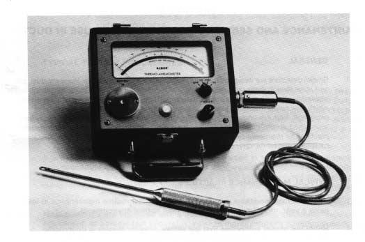
26 Figure 7-7: Thermo-Anemometer 23
27 SECTION 8 MAINTENANCE AND SERVICE OF DETECTORS FOR USE IN DUCTS 8.1. GENERAL Smoke detectors are designed to be as maintenance-free as possible. However, dust, dirt, and other foreign matter can accumulate inside a detector and change its sensitivity; this is especially true with duct type smoke detectors. They can become more sensitive, which may cause unwanted alarms, or less sensitive, which may reduce the level of protection. Both are undesirable. Therefore, detectors should be tested periodically and maintained at regular intervals. Follow closely the manufacturer s specific recommended practices for maintenance and testing. Also refer to Section 4-4 and Appendix B of NFPA 90A, and Chapter 7 of NFPA TYPICAL MAINTENANCE PRACTICES Under normal conditions detectors require routine maintenance at least twice a year, more frequently in dirtier than normal environments Notify the proper authorities that the smoke detector system is undergoing maintenance, and therefore the system will be temporarily out of service. CAUTION: Disable the zone or system undergoing maintenance to prevent unwanted alarms and possible dispatch of the fire department Most duct smoke detectors have detector heads that can be accessed for cleaning. Use a vacuum cleaner and remove dust from the detector by placing the nozzle as close as possible to the openings in the outside housing. A nozzle with a brush attachment will assist in dust removal. Some detectors can be removed for more thorough cleaning; refer to manufacturer s recommended procedure for details. Also check the sampling tube holes to make sure they are not clogged Test each detector s sensitivity If a detector s sensitivity is within specifications, nothing further need be done to the detector. If the detector s sensitivity is outside specifications, replace the detector or follow the manufacturer s recommended procedure Restore the zone or system at the completion of testing Notify the proper authorities that testing has been completed and the system is back in service Other maintenance checks : Holes or cracks in duct work near vicinity of detector. Air leaks where detector housing or sampling tubes are attached to duct. 24
28 Dust accumulations in or on sampling tubes, sampling tube filters, and detector head. Wiring terminal screw tightness TYPICAL TESTING PROCEDURES All detectors should be: (a) Tested or inspected at least annually to ensure that they sample the air stream. (b) Tested at least annually causing them to initiate an alarm at their installed location to ensure that they are operative and produce the intended response. (c) Checked within one year after installation and every alternate year thereafter to assure that they are within their listed and marked sensitivity range It is not recommended that duct fires be used to test duct smoke detectors. This procedure does not provide a consistent, measurable method of determining if the detectors are performing properly. The test procedures and test equipment recommended by the detector manufacturer are the best way to test these detectors Most detectors are equipped with a built-in test mechanism, electronic metering equipment, or aerosol test apparatus. Refer to manufacturer s specifications for details Notify the proper authorities that the smoke detector system is being tested. All persons who would automatically receive a real fire alarm signal should be notified to prevent an unnecessary response Follow the manufacturer s recommended test methods If a detector functions properly and its sensitivity is within specifications, nothing further need be done to the detector. However the Routine Maintenance Procedure (described in Paragraph 8.2) is recommended. If a detector s sensitivity is not within specifications, it should be replaced, or refer to manufacturer s recommended procedure Restore the zone or system at the completion of the testing Notify all the persons contacted at the beginning of the test that testing has been completed and the system is again operational RECOMMENDED TESTING AND MAINTENANCE LOG PROCEDURES It is recommended that a permanent Detector Test Log be set up and maintained, with a record for each individual smoke detector in each building. Each detector should be clearly described with information on the type of detector, the model number, the serial number (if any), the location, and the type of environment. Data entries should include test dates, type of test mode, test results, maintenance, and comments. A sample detector test log page is shown on the following page. 25
29 Detector Test Log Detector Identification Information Manufacturer and Serial Date Detector Model: Number: Installed: Description of Detector Location: EXAMPLE: 3rd floor of west wing in elevator lobby. Test Results and Maintenance Data Date Tested Test Mode Test Results Maintenance Performed Comments EXAMPLE: detector test button passed none 26
30 WORLDWIDE MANUFACTURING AND DISTRIBUTION System Sensor 3825 Ohio Avenue St. Charles, Illinois 60174, USA Telephone: (630) Fax: (630) System Sensor Pittway Tecnologica S.p.A. Via Caboto, Trieste, Italy Telephone: Fax: System Sensor Far East Rm 903, Tower A, New Mandarin Plaza 14 Science Museum Road TST East, Kowloon, Hong Kong Telephone: Fax: System Sensor Europe, Ltd. Horsham Gates III, North Street Horsham, West Sussex RH13 5PJ United Kingdom Telephone: Fax: System Sensor Canada 6581 Kitimat Road Unit #7 Mississauga, Ontario Canada, L5N 3T5 Telephone: Fax: Corporate Headquarters In Europe In The Far East In The United Kingdom In Canada I $3.00 System Sensor 11/94
A GUIDE FOR PROPER USE OF SMOKE DETECTORS IN DUCT APPLICATIONS. Application Guide DUCT SMOKE DETECTORS
 Application Guide DUCT SMOKE DETECTORS I N D O O R A I R Q U A L I T Y A GUIDE FOR PROPER USE OF SMOKE DETECTORS IN DUCT APPLICATIONS Carrier Corporation 07/93 Rev.A 08/99 www.totaline.com Literature Number
D2E Duct Smoke Detector
 INSTALLATION AND MAINTENANCE INSTRUCTIONS D2E Duct Smoke Detector Specifications Operating Temperature: 20 to 60 C Storage Temperature: 20 to 60 C Humidity: 0% to 93% Relative Humidity Non-condensing Air
D350PL INTELLIGENT PHOTOELECTRONIC DUCT SMOKE DETECTOR WITH EXTENDED AIR SPEED RANGE INSTALLATION AND MAINTENANCE INSTRUCTIONS
 D350PL INTELLIGENT PHOTOELECTRONIC DUCT SMOKE WITH EXTENDED AIR SPEED RANGE INSTALLATION AND MAINTENANCE INSTRUCTIONS I56-1975-004R Before installing detectors, please thoroughly read the NEMA Guide for
DH100LP Air Duct Smoke Detector with Extended Air Speed Range
 INSTALLATION AND MAINTENANCE INSTRUCTIONS DH100LP Air Duct Smoke Detector with Extended Air Speed Range 3825 Ohio Avenue, St. Charles, Illinois 60174 1-800-SENSOR2, FAX: 630-377-6495 The Innovair DH100LP
DH200PL Intelligent Air Duct Smoke Detector with Extended Air Speed Range
 INSTALLATION AND MAINTENANCE INSTRUCTIONS DH200PL Intelligent Air Duct Smoke Detector with Extended Air Speed Range 3825 Ohio Avenue, St. Charles, Illinois 60174 800/736-7672, FAX: 630-377-6495 www.systemsensor.com
DH200PL Intelligent Air Duct Smoke Detector with Extended Air Speed Range
 INSTALLATION AND MAINTENANCE INSTRUCTIONS DH200PL Intelligent Air Duct Smoke Detector with Extended Air Speed Range 3825 Ohio Avenue, St. Charles, Illinois 60174 800-736/7672, FAX: 630-377-6495 Before
Air Specialties Express, 448 S. Main St., P. O. Box , Verona, WI Phone: (877) Fax: (608)
 Fax: (608)") FORM ASX-40021 INSTALLATION, OPERATING AND MAINTENANCE INSTRUCTIONS SM-501 Series Smoke Detectors, Model EXSAC and EXSAD (Ionization), EXSAJ and EXSAK (Photoelectric) Air Specialties Express, 448 S. Main
FORM ASX-40021 INSTALLATION, OPERATING AND MAINTENANCE INSTRUCTIONS SM-501 Series Smoke Detectors, Model EXSAC and EXSAD (Ionization), EXSAJ and EXSAK (Photoelectric) Air Specialties Express, 448 S. Main
Air Specialties Express, 448 S. Main St., P. O. Box , Verona, WI Phone: (877) Fax: (608)
 Fax: (608)") FORM ASX-40020 INSTALLATION, OPERATING AND MAINTENANCE INSTRUCTIONS SL-2000 Series Smoke Detectors, Model EXSAA and EXSAB (Ionization), EXSAG and EXSAH (Photoelectric) Air Specialties Express, 448 S. Main
FORM ASX-40020 INSTALLATION, OPERATING AND MAINTENANCE INSTRUCTIONS SL-2000 Series Smoke Detectors, Model EXSAA and EXSAB (Ionization), EXSAG and EXSAH (Photoelectric) Air Specialties Express, 448 S. Main
DH500 Intelligent Air Duct Smoke Detector Housing
 INSTALLATION AND MAINTENANCE INSTRUCTIONS DH500 Intelligent Air Duct Smoke Detector Housing 3825 Ohio Avenue, St. Charles, Illinois 60174 1-800-SENSOR2, FAX: 630-377-6495 www.systemsensor.com Specifications
INSTALLATION AND MAINTENANCE
 INSTALLATION AND MAINTENANCE DH100ACDCIA & DH100ACDCPA Air Duct Smoke Detector Before Installing ULC standard CAN/ULC-S524-M91 Standard For The Installation Of Fire Alarm Systems should be referenced for
Installation Instructions
 48/50A2,A3,A4,A5020-060, 48/50P2,P3,P4,P5030-100, 48/50N 75 to 105 Ton Return Smoke Detector Accessory Installation Instructions Part No. CRSMKDET002C00 CONTENTS GENERAL........................................
7251DH Intelligent Air Duct Smoke Detector
 INSTALLATION AND MAINTENANCE INSTRUCTIONS 7251DH Intelligent Air Duct Smoke Detector Specifications Length: Width: Depth: Weight: Operating Temperature Range: Operating Humidity Range: Duct Air Velocity:
TYPE C: RETURN AIR UNDER POSITIVE PRESSURE FROM SEPARATE BLOWER
 Installation Instructions Model AD-HR Air Duct Monitoring Housing INTRODUCTION The SIEMENS Model AD-HR is a sampling tube, air duct monitoring housing. When used with a compatible smoke detector, smoke
DH100ACDCI Ionization Air Duct Smoke Detector
 INSTALLATION AND MAINTENANCE INSTRUCTIONS Ionization Air Duct Smoke Detector Before Installing Please thoroughly read the System Sensor Guide for Proper Use of Smoke Detectors in Duct Applications (A05-1004),
D350RPL INTELLIGENT PHOTOELECTRONIC DUCT SMOKE DETECTOR WITH EXTENDED AIR SPEED RANGE INSTALLATION AND MAINTENANCE INSTRUCTIONS
 D350RPL INTELLIGENT PHOTOELECTRONIC DUCT SMOKE WITH EXTENDED AIR SPEED RANGE INSTALLATION AND MAINTENANCE INSTRUCTIONS Before installing detectors, please thoroughly read the NEMA Guide for Proper Use
Shut Down The Fan: A Reprise by Dean K. Wilson, P.E.
 Fire Alarm Notebook by Dean K. Wilson. P.E. Page 1 Shut Down The Fan: A Reprise by Dean K. Wilson, P.E. Question: My grandfather passed away last summer. He had spent many years as a fire fighter. Among
FX-PDD Duct Smoke Detector Installation Sheet
 FX-PDD Duct Smoke Detector Installation Sheet Table 2: LEDs LED Power LED Alarm/active LED Off when the detector is in the alarm state. Flashes intermittently when the detector is in the normal state.
DNRHS Intelligent Air Duct Smoke Detector
 INSTALLATION AND MAINTENANCE INSTRUCTIONS DNRHS Intelligent Air Duct Smoke Detector Specifications Length: Width: Depth: Weight: Operating Temperature Range: Operating Humidity Range: Duct Air Velocity:
E-PDD Duct Smoke Detector Installation Sheet
 E-PDD Duct Smoke Installation Sheet E-PDD operation The duct smoke detector's primary purpose is to provide early warning of an impending fire and shut down the HVAC unit in order to prevent smoke from
DH500ACDC Intelligent Air Duct Smoke Detector Housing
 INSTALLATION AND MAINTENANCE INSTRUCTIONS DH500ACDC Intelligent Air Duct Smoke Detector Housing 3825 Ohio Avenue St. Charles, Illinois 60174 1-800-SENSOR2, FAX: 630-377-6495 Specifications Length: 14.5
DH100ACDCI Ionization Air Duct Smoke Detector
 INSTALLATION AND MAINTENANCE INSTRUCTIONS Ionization Air Duct Smoke Detector Before Installing Please thoroughly read the System Sensor Guide for Proper Use of Smoke Detectors in Duct Applications (A05-1004),
DH200RPL Intelligent Air Duct Smoke Detector with Extended Air Speed Range
 INSTALLATION AND MAINTENANCE INSTRUCTIONS DH200RPL Intelligent Air Duct Smoke Detector with Extended Air Speed Range 3825 Ohio Avenue, St. Charles, Illinois 60174 800/736-7672, FAX: 630-377-6495 Before
Installation Manual: PAD100-DUCTR Analog Addressable Duct Detector
 Installation Manual: PAD100-DUCTR Analog Addressable Duct Detector NOTICE TO THE INSTALLER This manual provides an overview and the installation instructions for the PAD100-DUCTR module. This module is
SK-Duct Air Duct Smoke Detector
 INSTALLATION AND MAINTENANCE INSTRUCTIONS I56-3432-001R 12 Clintonville Road Northford, CT 06472 203.484.7161; Fax: 203.484.7118 SK-Duct Air Duct Smoke Detector http://www.silentknight.com Specifications
A P P L I C A T I O N S G U I D E. Single-Ended Reflected Beam Smoke Detector
 A P P L I C A T I O N S G U I D E Single-Ended Reflected Beam Smoke Detector A P P L I C A T I O N S G U I D E Single-Ended Reflected Beam Smoke Detector Contents Section 1 Principles of Operation............................................................................
DETECTOR TEST LOG. Detector Identification Information DHX-501 INTELLIGENT AIR DUCT SMOKE DETECTOR HOUSING INSTALLATION AND MAINTENANCE INSTRUCTIONS
 TEST LOG Detector Identification Information Manufacturer and Serial Date Detector Model: Number: Installed: Description of Detector Location: Test Results and Maintenance Data Date Test Test Maintenance
DH400 Air Duct Smoke Detector
 INSTALLATION AND MAINTENANCE INSTRUCTIONS DH400 Air Duct Smoke Detector Before Installing Please thoroughly read System Sensor s Guide for Proper Use of Smoke Detectors in Duct Applications (I56-473-XX),
Climate Control System
 Page 1 of 13 SECTION 412-00: Climate Control System General Information DESCRIPTION AND OPERATION 1998 Mark VIII Workshop Manual Climate Control System Cautions and Warnings WARNING: To avoid accidental
ENVIRO UNIT ENGINEERING MANUAL KES SERIES
 ENVIRO UNIT ENGINEERING MANUAL KES SERIES The Cadexair INC. Enviro System (KES) and Recirculation System (KRS) have been designed and constructed specifically for a commercial kitchen exhaust. The units
DH100ACDCLP Air Duct Smoke Detector with Extended Air Speed Range
 INSTALLATION AND MAINTENANCE INSTRUCTIONS Air Duct Smoke Detector with Extended Air Speed Range A Division of Pittway 825 Ohio Avenue, St. Charles, Illinois 60174 1-800-SENSOR2, FAX: 60-77-6495 The Innovair
F25F Media Air Cleaner
 F25F Media Air Cleaner FEATURES PRODUCT DATA High efficiency media filter captures particles as small as 1.0 micron. Efficiency and arrestance ratings based on the American Society of Heating, Refrigerating
TRN100BPT, TRN100BP, and TRN100BPC Air Duct Smoke Detector with Extended Air Speed Range
 INSTALLATION AND MAINTENANCE INSTRUCTIONS TRN100BPT, TRN100BP, and TRN100BPC Air Duct Smoke Detector with Extended Air Speed Range 825 Ohio Avenue, St. Charles, Illinois 60174 1-800-SENSOR2, FAX: 60-77-6495
NEMA Standards Publication. Guide for Proper Use of Smoke Detectors in Duct Applications
 NEMA Standards Publication Guide for Proper Use of Smoke Detectors in Duct Applications Published by: National Electrical Manufacturers Association 1300 North 17th Street, Suite 1752 Rosslyn, Virginia
Appendix 13. Categories of Cooling and Heating systems
 EcoShopping - Energy efficient & Cost competitive retrofitting solutions for Shopping buildings Co-funded by the European Commission within the 7 th Framework Programme. Grant Agreement no: 609180. 2013-09-01
SECTION PLUMBING/HVAC FINAL TESTING, ADJUSTING AND BALANCING
 SECTION 15990 PLUMBING/HVAC FINAL TESTING, ADJUSTING AND BALANCING PROJECT NO. ####### PART I - GENERAL 1.01 WORK INCLUDED A. Final test and balance of air distribution systems. B. Final test and balance
PRODUCT OVERVIEW SM-501 AT-A-GLANCE
 AIR PRODUCTS AND CONTROLS INC. INSTALLATION AND MAINTENANCE INSTRUCTIONS FOR SM-501 SERIES DUCT SMOKE DETECTORS SM-501-N SM-501-P PRODUCT APPLICATION SM-501 Series duct smoke detectors provide early detection
B. Use UT Austin specifications and equipment schedule format for HVAC equipment where available.
 PART 1: GENERAL 1.01 General Requirements A. This standard is intended to provide useful information to the Professional Service Provider (PSP) to establish a basis of design. The responsibility of the
DNRECL Eclipse Duct Smoke Detector
 INSTALLATION AND MAINTENANCE INSTRUCTIONS DNRECL Eclipse Duct Smoke Detector 3825 Ohio Avenue, St. Charles, Illinois 60174 1-800-SENSOR2, FAX: 630-377-6495 www.systemsensor.com SPECIFICATIONS Operating
DNR Duct Smoke Detector
 INSTALLATION AND MAINTENANCE INSTRUCTIONS I56-3051-004R DNR Duct Smoke Detector Specifications Operating Temperature: 4 to 158 F ( 20 to 70 C); 32 F to 120 F (0 C to 49 C) with module installed in the
Code of Practice for Design, Installation, Commissioning & Maintenance of Duct Smoke Detector (DSD) Systems
 Systems") Code of Practice for Design, Installation, Commissioning & Maintenance of Duct Smoke Detector (DSD) Systems Issue 1.0 Page 1 of 35 Fire Industry Association Code of Practice for Design, Installation, Commissioning
Code of Practice for Design, Installation, Commissioning & Maintenance of Duct Smoke Detector (DSD) Systems Issue 1.0 Page 1 of 35 Fire Industry Association Code of Practice for Design, Installation, Commissioning
2. The Group F occupancy has have an a combined occupant load of 500 or more above or below the lowest level of exit discharge.
 2. The Group F occupancy has have an a combined occupant load of 500 or more above or below the lowest level of exit discharge. Exception: Manual fire alarm boxes are not required where the building is
INSTALLATION AND OPERATIONS MANUAL
 email: info@uapc.com Main Office: Telephone: 757-461-0077 1140 Kingwood Ave, Norfolk, Virginia 23502 Telefax: 757-461-0808 Branch Offices: Telephone: 704-374-0600 4715 Stockholm Court, Charlotte, NC 28273
INSTRUCTIONS. Duct Mount Kit Q900. Description. Operation
 INSTRUCTIONS Duct Mount Kit Q900 Description The Detector Electronics Model Q900 Duct Mount Kit is used with the Model PIRECL PointWatch Eclipse IR gas sensor to detect combustible hydrocarbon gases within
DUCT SMOKE DETECTORS IQ8
 Marcin Cichy 11.2017 DUCT SMOKE DETECTORS IQ8 Special fire alarm detectors EN 54-27 duct smoke detectors EN 54-27:2015 Fire detection and fire alarm systems Part 27: Duct smoke detectors New standard introduced
Boiler Draft Equipment
 Boiler Draft Equipment Learning Outcome When you complete this module you will be able to: Discuss, sketch and describe the basic equipment used to supply combustion air to a boiler furnace. Learning Objectives
ANNEX AMENDMENTS TO THE INTERNATIONAL CODE FOR FIRE SAFETY SYSTEMS (FSS CODE) CHAPTER 1 GENERAL
 CHAPTER 1 GENERAL") Annex 2, page 2 ANNEX AMENDMENTS TO THE INTERNATIONAL CODE FOR FIRE SAFETY SYSTEMS (FSS CODE) CHAPTER 1 GENERAL Section 1 Application 1 The following new sentence is added to the end of paragraph 1.2:
Annex 2, page 2 ANNEX AMENDMENTS TO THE INTERNATIONAL CODE FOR FIRE SAFETY SYSTEMS (FSS CODE) CHAPTER 1 GENERAL Section 1 Application 1 The following new sentence is added to the end of paragraph 1.2:
You in Control PRODUCT OVERVIEW
 AIR PRODUCTS AND CONTROLS You in Control AIR PRODUCTS AND CONTROLS INC. INSTALLATION AND MAINTENANCE INSTRUCTIONS FOR SERIES PLENUM DUCT SMOKE DETECTORS NO-FLOW LOW-FLOW SPECIAL APPLICATION -N -P PRODUCT
DNR Duct Smoke Detector
 INSTALLATION AND MAINTENANCE INSTRUCTIONS I56-3051-007R DNR Duct Smoke Detector Specifications Operating Temperature: 4 to 158 F ( 20 to 70 C); 32 F to 120 F (0 C to 49 C) with module installed in the
Instructions. Duct Mount Accessory Q Rev: 11/
 Instructions Duct Mount Accessory Q5016 Rev: 11/16 95-8752 Table of Contents DESCRIPTION...1 FEATURES...1 OPERATION...1 SPECIFICATIONS.... 2 INSTALLATION... 2 Detector Location...2 Tools for Assembly...4
DNR-AUS Duct Smoke Detector
 INSTALLATION AND MAINTENANCE INSTRUCTIONS I56-3642-000R DNR-AUS Duct Smoke Detector Specifications Operating Temperature: 20 to 70 C ( 4 to 158 F) 0 C to 49 C (32 F to 120 F) with module installed in the
Adv. 8.4 Guidelines for Biosafety Cabinets Rev
 UNIVERSITY OF CINCINNATI Environmental University Health Services 556-4968 Health and Safety ADVISORY NO. 8.4: GUIDELINES FOR THE SELECTION, INSTALLATION AND USE OF BIOSAFETY CABINETS (INCLUDING ISSUES
DFE T ECHNOLOGY. At Conceptronic, the design and management process for reflow soldering systems is called Dynamic Flow Engineering, or DFE.
 DFE T ECHNOLOGY As components become smaller, component mixes become more diverse, and board densities continue to increase, the processes of packaging, interconnection, and assembly are challenging the
EXTINGUISHING SYSTEM DETECTION AND CONTROL
 GAP.13.0.1 A Publication of Global Asset Protection Services LLC EXTINGUISHING SYSTEM DETECTION AND CONTROL INTRODUCTION Extinguishing systems require prompt detection systems so they operate quickly and
IMPORTANT WARNINGS IMPORTANT SAFETY INSTRUCTIONS
 IMPORTANT WARNINGS IMPORTANT SAFETY INSTRUCTIONS Suncourt recommends professional installation of the Airiva (or by an accomplished DIY person) Please read and save these entire instructions before starting
TABLE OF CONTENTS HOW AIRBORNE CONTAMINATION IS REMOVED 3 DIMENSIONS 4 SPECIFICATIONS 6 PLANNING THE INSTALLATION 7 ASSEMBLY & INSTALLATION 10
 TABLE OF CONTENTS PAGE HOW AIRBORNE CONTAMINATION IS REMOVED 3 DIMENSIONS 4 SPECIFICATIONS 6 PLANNING THE INSTALLATION 7 ASSEMBLY & INSTALLATION 10 CHECKOUT 16 MAINTENANCE 18 TROUBLE SHOOTING 21 PARTS
Chapter 17, Initiating Devices
 Chapter 17, Initiating Devices Summary. Chapter 17 was Chapter 5 in NFPA 72-2007. The term authority having jurisdiction is replaced in some sections by the term other governing laws, codes, or standards.
Chilled Water DOAS Fan Powered Terminal Units
 Chilled Water DOAS Fan Powered Terminal Units CHILLED WATER DOAS FAN POWERED TERMINAL UNITS DOAS TERMINAL UNITS FEATURES AND BENEFITS MINIMUM VENTILATION CONTROL The DOAS unit provides the Designer, Owner
Installation Instructions
 FAVXXR6C2100-A01 Vent Damper and Control Installation Instructions FAMILIARIZE YOURSELF WITH THE INSTALLATION INSTRUCTIONS BEFORE STARTING ATTENTION INSTALLER: This product must be installed by a qualified
Duct smoke housings, 4-wire D341/D341P and D342/D342P
 Duct smoke housings, 4-wire D341/D341P and D342/D342P en Installation manual Duct smoke housings, 4-wire Notices en 3 1 Notices These instructions cover the installation of the D341/D342 Duct smoke housings
Union County Vocational - Technical Schools Scotch Plains, New Jersey
 SECTION 230593 - TESTING, ADJUSTING, AND BALANCING FOR HVAC PART 1 - GENERAL 1.1 SUMMARY A. Section Includes: 1. Balancing Air Systems: a. Constant-volume air systems. b. Variable-air-volume systems. 2.
AIR DISTRIBUTION. C. Section Building Automation and Control System Guidelines. D. Section Fire Alarm System & Detection Systems
 233100 AIR DISTRIBUTION PART 1: GENERAL 1.01 RELATED SECTIONS A. Section 230700 HVAC Insulation B. Section 237300 Air Handling C. Section 230900 Building Automation and Control System Guidelines D. Section
DUCT SYSTEMS CHAPTER 6
 SECTION 601 GENERAL 601.1 Scope. Duct systems used for the movement of air in air-conditioning, heating, ventilating and exhaust systems shall conform to the provisions of this chapter except as otherwise
1998 Expedition/Navigator Workshop Manual
 Page 1 of 8 SECTION 412-00: Climate Control System - General Information 1998 Expedition/Navigator Workshop Manual DESCRIPTION AND OPERATION Procedure revision date: 02/11/2000 Climate Control System WARNING:
RESOLUTION MSC.292(87) (adopted on 21 May 2010) ADOPTION OF AMENDMENTS TO THE INTERNATIONAL CODE FOR FIRE SAFETY SYSTEMS
 (adopted on 21 May 2010) ADOPTION OF AMENDMENTS TO THE INTERNATIONAL CODE FOR FIRE SAFETY SYSTEMS") RESOLUTION MSC.292(87) THE MARITIME SAFETY COMMITTEE, RECALLING Article 28(b) of the Convention on the International Maritime Organization concerning the functions of the Committee, NOTING resolution MSC.98(73)
RESOLUTION MSC.292(87) THE MARITIME SAFETY COMMITTEE, RECALLING Article 28(b) of the Convention on the International Maritime Organization concerning the functions of the Committee, NOTING resolution MSC.98(73)
Please refer to the drawing and notes for each particular plan view. Site Plan S1-1 Site Drawing. Electrical E1-1 Main Electrical Drawing
 The property that I discuss is an actual property that I helped to build. My position was as the Facility/Project Manager while the building was under construction. I worked very closely with the Senior
ASHRAE JOURNAL ON REHEAT
 Page: 1 of 7 ASHRAE JOURNAL ON REHEAT Dan Int-Hout Chief Engineer Page: 2 of 7 Overhead Heating: A lost art. March 2007 ASHRAE Journal Article Dan Int-Hout Chief Engineer, Krueger VAV terminals provide
LaserFOCUS VLF-250 Engineering Specification
 Vision Fire & Security LaserFOCUS VLF-250 Engineering Specification May 2004 Part Number 20296 LaserFOCUS VESDA 2 VESDA LaserFOCUS Contents Scope...4 Description...4 General...4 Approvals...4 Codes, Standards
College of Technological Studies Department of Power & Refrigeration Technology. Course Contents
 College of Technological Studies Department of Power & Refrigeration Technology Course Contents Course Designation: Air Conditioning Control systems Course No. : 272 0463 Credit Hrs.: 3 Lecture Hrs.: 2
Topic 2. ME 414/514 HVAC Systems Overview Topic 2. Equipment. Outline
 ME 414/514 HVAC Systems Overview Equipment Outline 2-1 The Complete System 2-2 The Air-Conditioning and Distribution System 2-3 Mechanical Equipment Air-handling Equipment Heating Equipment Boilers Furnaces
Installation Instructions
 CRSMKKIT002A00 CRSMKSEN002A00 FIELDINSTALLEDSMOKEDETECTORS FOR MEDIUM ROOFTOP UNITS 15 to 25 TONS Installation Instructions TABLE OF CONTENTS PACKAGE CONTENTS... 1 SAFETY CONSIDERATIONS... 1 GENERAL...
Summary of BBS Proposed Ohio Mechanical Code Rule Changes October 2016
 Summary of BBS Proposed Ohio Mechanical Code Rule Changes October 2016 Ohio Administrative Code Rule Number OMC Section IMC origin Reason for proposed 4101:2-2-01 Air, Makeup 2015 Modified definition Air,
DUCT SYSTEMS CHAPTER 6
 CHAPTER 6 DUCT SYSTEMS SECTION 601 GENERAL 601.1 Scope. Duct systems used for the movement of air in air-conditioning, heating, ventilating and exhaust systems shall conform to the provisions of this chapter
5.0 Installation Instructions
 5.0 Installation Instructions 5.1 Location Within the laboratory, pharmacy, etc., the ideal location of the biological safety cabinet is away from personnel traffic lanes, air vents (in or out), doors
PRODUCT OVERVIEW. SL-2000 AT-A-GLANCE MODEL NUMBER: SL-2000-N 4-Wire Ionization Duct Smoke Detector SL-2000-P 4-Wire Photoelectric Duct Smoke Detector
 AIR PRODUCTS AND CONTROLS You in Control AIR PRODUCTS AND CONTROLS INC. INSTALLATION AND MAINTENANCE INSTRUCTIONS FOR SERIES DUCT SMOKE DETECTORS -N 4-Wire, Ionization Type -P 4-Wire, Photoelectric Type
How to Take Basic Readings to Show Energy Efficiency
 How to Take Basic Readings to Show Energy Efficiency NADCA Energy White Paper Readings & Copyright 2017 NADCA, All Rights Reserved No part of this publication may be reproduced or distributed by any means,
Fire Detection System: An Overview
 Fire Detection System: An Overview Arief Rahman Thanura Process & Control Engineer VICO Indonesia, LLC Member of ISA Introduction Fire accidents had happened all around the world and more concern raised
SPECIFIC APPLIANCES CHAPTER 6
 CHAPTER 6 SPECIFIC APPLIANCES SECTION FGC 601 GENERAL 601.1 Scope. This chapter shall govern the approval, design, installation, construction, maintenance, alteration and repair of the appliances and equipment
Use this Construction/HVAC Glossary to answer the questions below.
 www.garyklinka.com Page 1 of 21 Instructions: 1. Print these pages. 2. Circle the correct answers and transfer to the answer sheet on the second last page. 3. Page down to the last page for the verification
SPECIFIC APPLIANCES CHAPTER 6
 CHAPTER 6 SPECIFIC APPLIANCES SECTION 601 GENERAL 601.1 Scope. This chapter shall govern the approval, design, installation, construction, maintenance, alteration and repair of the appliances and equipment
BOOK 1 OVERVIEW RD2XRT INSTALLATION AND OPERATION MANUAL. Table of Contents ABOUT BOOK 1:
 4510 Helgesen Drive, Madison, WI, 53718 608.221.4499, 800.627.4499, Fax: 608.221.2824 support@renewaire.com www.renewaire.com RD2XRT INSTALLATION AND OPERATION MANUAL BOOK 1 OVERVIEW ABOUT BOOK 1: This
EqUIPMENT LAYOUT MANUAL
 Bulletin 311-E Metric NEW! EqUIPMENT LAYOUT MANUAL For Cooling Towers, Evaporative Condensers, Closed Circuit Coolers Reduced Clearance Dimensions with EVAPCO Induced Draft Counterflow Products 3 Table
Duct smoke housing, 2-wire D340/D340P
 Duct smoke housing, 2-wire D340/D340P en Installation manual Duct smoke housing, 2-wire Notices en 3 1 Notices These instructions cover the installation of the D340 Duct smoke housing and D340P Duct smoke
Pharmaceutical Facility Design
 PhEn-602 Pharmaceutical Facility Design J. Manfredi Notes 9A PhEn-602 J. Manfredi 1 Primary & Secondary HVAC units Primary Primary air handling unit arrangement: One unit is responsible for all of the
WKS 2200 SERIES (USA only) --INSTALLATION INSTRUCTIONS--
 --INSTALLATION INSTRUCTIONS--") 8610 Production Avenue San Diego, California 92121 (858) 566-7465 Fax (858) 566-1943 WWW.BREEZAIRE.COM WKS 2200 SERIES (USA only) --INSTALLATION INSTRUCTIONS-- Thank you for choosing a BREEZAIRE cooling
8610 Production Avenue San Diego, California 92121 (858) 566-7465 Fax (858) 566-1943 WWW.BREEZAIRE.COM WKS 2200 SERIES (USA only) --INSTALLATION INSTRUCTIONS-- Thank you for choosing a BREEZAIRE cooling
Desiccant Dehumidifier
 Since the 1950s Desiccant Dehumidifier Dry Spaces With NO Added Heat BMIL Technologies, LLC 4915 Arendell St., #313 Morehead City, NC 28557 PH 252-727-0994 FAX 252-727-0996 WWW.BMIL.COM Product Description
CHAPTER 5: EXHAUST SYSTEMS
 MOTORS, FANS AND FILTERS 503.1 General. Motors and fans shall be sized to provide the required air movement. Motors in areas that contain flammable vapors or dusts shall be of a type approved for such
Life Safety Damper Installation ASHRAE St Louis Chapter Feb. 9,2015. Peter McDonnell, PE, LEED AP BD+C McClure Engineering
 Life Safety Damper Installation ASHRAE St Louis Chapter Feb. 9,2015 Peter McDonnell, PE, LEED AP BD+C McClure Engineering UL DAMPER TEST STANDARDS UL 555 - FIRE DAMPERS UL555S SMOKE DAMPERS UL555C CEILING
APPLICATION, INSTALLATION, AND MAINTENANCE MANUAL CA2XRT, CA3XRT, CA4XRT
 4510 Helgesen Drive, Madison, WI 53718 (608) 221-4499, (800) 627-4499, Fax: (608) 221-2824 support@renewaire.com www.renewaire.com APPLICATION, INSTALLATION, AND MAINTENANCE MANUAL CA2XRT, CA3XRT, CA4XRT
Installation Instructions Remote Blowers
 Installation Instructions Remote Blowers Models: REMP3, REMP16 Suitable for use in a household cooking area. Suitable for use with solid state controls. To complete this blower, a Dacor hood assembly or
System Components with ` Emphasis on Packaged Rooftop Application and Installation. Jerry Cohen President Jacco & Assoc.
 System Components with ` Emphasis on Packaged Rooftop Application and Installation Jerry Cohen President Jacco & Assoc. Agenda Define and relate in practical terms the following components: System Effect
Selecting an Environmental Test Chamber
 Selecting an Environmental Test Chamber Eric Berchtold, Cincinnati Sub-Zero Cincinnati Sub-Zero Products, LLC 12011 Mosteller Road Cincinnati, Ohio 45241 513-772-8810 www.cszindustrial.com 1 Selecting
AGN 088 Air Flow and Cooling
 Application Guidance Notes: Technical Information from Cummins Generator Technologies AGN 088 Air Flow and Cooling COOLING AIR FOR AN ALTERNATOR Both open air ventilated alternators and enclosed alternators
LEARNING SPECIAL HAZARD DETECTION TYPES
 LEARNING SPECIAL HAZARD DETECTION TYPES JUNE 2013 COPYRIGHT CLIMATEC SPECIAL HAZARDS DETECTION TYPES EXPLAINED STAGE ONE DETECTION - ACTIVE AIR SAMPLING\\INCIPIENT AND IN- VISIBLE SMOKE STAGE AIR SAMPLING
Filtrex A Smoke Detector for Difficult Environments
 A P P L I C A T I O N S G U I D E Filtrex A Smoke Detector for Difficult Environments A P P L I C A T I O N S G U I D E Filtrex A Smoke Detector for Difficult Environments Contents Section 1 Product Overview...2
BOOK 1 OVERVIEW RD2XIN INSTALLATION AND OPERATION MANUAL. Table of Contents ABOUT BOOK 1:
 4510 Helgesen Drive, Madison, WI, 53718 608.221.4499, 800.627.4499, Fax: 608.221.2824 support@renewaire.com www.renewaire.com RD2XIN INSTALLATION AND OPERATION MANUAL BOOK 1 OVERVIEW ABOUT BOOK 1: This
AUTOMATIC MAKE-UP AIR DAMPER WITH TRANSFORMER READ AND SAVE THESE INSTRUCTIONS
 AUTOMATIC MAKE-UP AIR DAMPER WITH READ AND SAVE THESE INSTRUCTIONS FOR RESIDENTIAL USE ONLY Page 1 WARNING TO REDUCE THE RISK OF FIRE, ELECTRIC SHOCK, OR INJURY TO PERSONS, OBSERVE THE FOLLOWING: 1. Installation
DUCTSD Duct Smoke Detector
 INSTALLATION AND MAINTENANCE INSTRUCTIONS 82 Ohio Avenue, St. Charles, Illinois 07-800-SENSOR2, FAX: 0-77-9 Duct Smoke Detector www.systemsensor.com SPECIFICATIONS Operating Temperature: to 8 F ( to 70
How about Savings in Time, Money, Energy and Longer Life?
 Chapter 17: The Value of Maintaining Evaporative Cooling Equipment 97 The Value 17 of Maintaining Evaporative Cooling Equipment 1. Cooling Tower Maintenance and Upgrades... What s in it for You? How about
a) Establishment of emergency procedures to be followed at the time of an emergency;
 Establishment of emergency procedures to be followed at the time of an emergency;") 5.10 Fire Safety 5.10.1 Introduction The Corporation is responsible for carrying out the provisions of the Ontario Fire Code. This section outlines our responsibilities as well as inspections and testing
5.10 Fire Safety 5.10.1 Introduction The Corporation is responsible for carrying out the provisions of the Ontario Fire Code. This section outlines our responsibilities as well as inspections and testing
SANTA ROSA FIRE DEPARTMENT FIRE PREVENTION BUREAU PLAN REVIEW CHECKLIST FIRE ALARM SYSTEM INSTALLATION
 July 1, 2010 SANTA ROSA FIRE DEPARTMENT FIRE PREVENTION BUREAU PLAN REVIEW CHECKLIST FIRE ALARM SYSTEM INSTALLATION Address: Permit #: Inspector: Date: Status: Inspector: Date: Status: A-Approved; AC-Approved