User s Guide OSXL-101. Compact Thermal Image Sensor Application Software. Shop online at. omega.com
|
|
|
- Allyson Casey
- 6 years ago
- Views:
Transcription
 COPYRIGHT 2009 OMEGA ENGINEERING, INC.")
1 User s Guide Shop online at Windows 98/Windows 2000/ Windows XP (Windows 2000/Windows XP are recommended) OSXL-101 Compact Thermal Image Sensor Rev omega.com info@omega.com For latest product manuals: omegamanual.info MADE IN JAPAN ENGINEERING, INC. omega.com 800-TC-OMEGA ( ) COPYRIGHT 2009 OMEGA ENGINEERING, INC. OSXL-101 Compact Thermal Image Sensor Application Software
2 OMEGAnet Online Service omega.com Internet Servicing North America: U.S.A.: Omega Engineering, Inc., One Omega Drive, P.O. Box 4047 ISO 9001 Certified Stamford, CT USA Toll Free: TEL: (203) FAX: (203) Canada: 976 Bergar Laval (Quebec), Canada H7L 5A1 Toll-Free: TEL: (514) FAX: (514) For immediate technical or application assistance: U.S.A. and Canada: Sales Service: /1-800-TC-OMEGA Customer Service: / BEST Engineering Service: /1-800-USA-WHEN Mexico: En Español: 001 (203) FAX: (001) Benelux: Servicing Europe: Managed by the United Kingdom Office Toll-Free: TEL: FAX: Czech Republic: Frystatska Karviná, Czech Republic Toll-Free: TEL: FAX: France: Managed by the United Kingdom Office Toll-Free: TEL: +33 (0) FAX: +33 (0) Germany/Austria: Daimlerstrasse 26 D Deckenpfronn, Germany Toll-Free: TEL: +49 (0) FAX: +49 (0) info@omega.de United Kingdom: ISO 9001 Certified OMEGA Engineering Ltd. One Omega Drive, River Bend Technology Centre, Northbank Irlam, Manchester M44 5BD England Toll-Free: TEL: +44 (0) FAX: +44 (0) sales@omega.co.uk It is the policy of OMEGA Engineering, Inc. to comply with all worldwide safety and EMC/EMI regulations that apply. OMEGA is constantly pursuing certification of its products to the European New Approach Directives. OMEGA will add the CE mark to every appropriate device upon certification. The information contained in this document is believed to be correct, but OMEGA accepts no liability for any errors it contains, and reserves the right to alter specifications without notice. WARNING: These products are not designed for use in, and should not be used for, human applications.
3 Introduction Thank you for purchasing a compact thermal image sensor. In order to use this product safely, please read this instruction manual completely before use and confirm the correct handling and instructions. In addition, please retain this instruction manual for future reference. Before using Please confirm the contents of packing. If something is missing, please contact your nearest distributor. Names Quantity Compact thermal image sensor 1 Custom Power/Alarm output cable 1 Custom Network cable 1 Universal head 1 Lens cap 1 Connector cap 1 Mounting screw (already mounted to the product) 1 Application software (CD) Instruction manual (Sensor/application software) (CD) 1 Power supply w/cable 2.5 m (8.2 ft) Quick manual 1 1 About this instruction manual Under absolutely no circumstances may the contents of this instruction manual, in part or in whole, be transcribed or copied without permission. The contents in this instruction manual are subject to change without notice in future. The figures in this instruction manual may be emphasized, simplified or omitted. Every effort has been made to ensure that the details of this manual are accurate. However, should any errors be found or important information be omitted, please inform your nearest distributor. The company names and brand names used in this manual are the trademarks or registered trademarks of respective companies. About exemption from responsibility Unless otherwise specified in the guarantee clauses, we do not offer any guarantee about this product. We shall not be liable to a customer or a third party for any damages or indirect damages by using this product or by unpredictable defects of the product. Hardware requirements Compatible PC : DOS/V compatible *.NET Framework 2.0 or later has been installed and runs correctly. * Display resolution: 800 x 600 pixels or more (recommended) OS : Windows 2000 (SP4 or later)/xp/vista_(windows XP or later recommended) *.NET Framework 2.0 or later (required) Communication port : LAN Hard disk : 150MB or more free space for installation Memory : Windows 2000/XP 1GB recommended (512MB or more) : Windows Vista 2GB or more recommended CPU : Windows 2000/XP 1.5GHz or faster recommended : Windows Vista_ 2GHz or faster recommended Microsoft and Windows are either trademarks or registered trademarks of Microsoft Corporation, USA. Intel and Pentium are either trademarks or registered trademarks of Intel Corporation, USA. I
4 Safety precautions The safety precautions shown in this manual indicate the important contents about safety. Please be sure to understand and follow these precautions. In this manual, in order to use this product safely, the precautions are described with the following indications and marks. Warning Caution This indicates a potentially hazardous situation that, if not avoided, will result in death or serious injury. This indicates a potentially hazardous situation that, if not avoided, may result in minor or moderate injury or cause property damage. [Safety precautions] Warning Do not use the connecting cable other than the original use. Do not connect the connecting cable by wet hands. It may cause an electric shock. Do not connect the connecting cable when the thermal image sensor or the connecting cable is wet. It may cause an electric shock or fire by a short circuit. When the connecting cable is connected, be careful not to wet the thermal image sensor or the connecting cable with water, etc. It may cause an electric shock or fire by a short circuit. Do not place the connecting cable or the CD to a place subjected to direct sunlight or a high temperature place. In addition, do not leave them in a car of which temperature become high for a long time. It may cause discoloration, deformation or damage of them. Furthermore, when you connect products to be used by combining with this product, follow the instruction manual for this product. If you do not follow the instructions, we do not guarantee safety. Precautions for use Caution Store the CD in a place not subjected to direct sunlight and protect it against dust/dirt or liquid like water, etc. Handle the CD carefully. Data cannot be read if its data side and label side are scratched. Do not apply too much force on the connecting cable. For the connection and removal of the cable, straight insert or pull out it by holding the connector. It may cause damage of the cable or the thermal image sensor. Do not wet the connecting cable by water, etc. When the cable is wet, dry it fully to use. II
5 Contents Introduction... Safety precautions... Precautions for use... Outline of product... 1 Operation flowchart... 2 Preparation before using... 3 Installation of application software... 4 Starting application software... 7 Uninstall of application software... 8 LAN setting of thermal image sensor 1. Initialization of thermal Image sensor PC settings Connection of thermal image sensor and PC Network settings of thermal image sensor Initial settings of application software Display of thermal images Screen configuration and explanation Image/Data File (F) Sensor Setup (S) Network(Sensor) IP Address Alarm(Sensor) Procedure for setting alarms to sensor Emissivity settings Function (D) Temp Range Image Filter Rotation Max Temp/Min Temp Zone Trend Pixel EQ Windows Size Beep[On/Off] Zone Setup Help (H) Connection error Troubleshooting III

6 Outline of product 1. Main screen OSXL-101 Application Software OSXL-101 Application Software OSXL-101 ApplicationSoftware Alarm Trend graph Alarm judgment 1
7 Operation flowchart Image/Data File(F) Function (D) Help (H) Start Saving (R) Temp Range (R) Manual/auto Help (H) Stop Saving (P) Image/Data Setup(S) Frame average/ 9Pixel average/ 9pixel Median/ Rotation_Upside Down/Mirror Version (V) Sensor selection Saving interval & period Saving data format & directory Zone Trending(G) Trend Data (D) Sensor number IP address Subnet mask IP Address(I) IP address Sensor ID Sensor selection Windows Size(V) Standard 1.5 times Graph Data Save (S) Graph Data Auto Save (A) Zone Setup (G) Sensor selection Alarm area coordinates Contact output & alarm set values condition Image save & retrieve/delete Emissivity (E) Zone Setup (S) Zone setup Logging interval Alarm Setup Data Filter Sensor selection Emissivity 2
8 Preparation before using Installation of this application software to your PC Application software installation Page 4 ~ Connection of the thermal image sensor and the PC with supplied custom network cable Thermal image sensor LAN setting Page 9 ~ Running of the application software for initial settings Application software activation Page 7 ~ Application software initial settings Page 15 ~ Ready to use 3


9 Installation of application software The following is the installation procedure of the application software. (The procedure is for Windows XP.) 1. Start your PC and launch Windows. Before this application software is installed, close all other applications that are running. If not, the installation may be affected from them. 2. Insert the CD with the OMEGA application software. Setup Wizard should start automatically. If not, double-click the setup program in the CD to start. When the OS of your PC is Windows2000, Update Rollup 1 for SP4 and Internet Explorer (IE) 5.01 or later are required. The setup screen will appear. OSXL-101_ApplicationSoftVer2_00 Welcome to the OSXL-101_ApplicationSoftVer2_00 Setup Wizard The installer will guide you through the steps required to install OSXL-101_ApplicationSoftVer2_00 on your computer. Click [Next] button. OSXL-101_ApplicationSoftVer2_00 4
![3. [Installation folder selection] The following screen will appear. OSXL-101_ApplicationSoftVer2_00 The installer will install OSXL-101_ApplicationSoftVer2_00 to the following folder.](/docs-images/73/69427439/images/10-0.jpg "C: Program Files OMEGA OSXL-101_ApplicationSoftVer2_00 Install OSXL-101_ApplicationSoftVer2_00 for yourself, or for anyone who uses this computer: Specify directory and folder you want to install.")
![The default folder is [C:/program file/omega/osxl- 010 Application Soft]. In addition, select users who can use this application software. After the selections are completed, click [Next] button.](/docs-images/73/69427439/images/10-1.jpg "The drive number ([C:/], etc.) indicated may be changed depending on types of PC. Read the drive indications on the environment of the PC you are using. 4.")
10 3. [Installation folder selection] The following screen will appear. OSXL-101_ApplicationSoftVer2_00 The installer will install OSXL-101_ApplicationSoftVer2_00 to the following folder. C: Program Files OMEGA OSXL-101_ApplicationSoftVer2_00 Install OSXL-101_ApplicationSoftVer2_00 for yourself, or for anyone who uses this computer: Specify directory and folder you want to install. The default folder is [C:/program file/omega/osxl- 010 Application Soft]. In addition, select users who can use this application software. After the selections are completed, click [Next] button. The drive number ([C:/], etc.) indicated may be changed depending on types of PC. Read the drive indications on the environment of the PC you are using. 4. [Confirmation of installation] The following confirmation screen will appear. Click [Next] button to start the installation. OSXL-101_ApplicationSoftVer2_00 The installer is ready to install OSXL-101_ApplicationSoftVer2_00 on your computer: Before the installation, close all other applications that are running. If not, the installation may be affected by them. 5
![5. [The OSXL-101 application software is installed.] The installation will start.](/docs-images/73/69427439/images/11-0.jpg "OSXL-101_ApplicationSoftVer2_00 Installing OSXL-101_ApplicationSoftVer2_00 OSXL-101_ApplicationSoftVer2_00")

11 5. [The OSXL-101 application software is installed.] The installation will start. OSXL-101_ApplicationSoftVer2_00 Installing OSXL-101_ApplicationSoftVer2_00 OSXL-101_ApplicationSoftVer2_00 is being installed. After the installation is completed, the following screen will appear. After you confirm it, press [Close] button to quit. OSXL-101_ApplicationSoftVer2_00 OSXL-101_ApplicationSoftVer2_00 has been sucessfully installed. 6

![[Method 1] Double-click the icon on the desktop.](/docs-images/73/69427439/images/12-1.jpg "OSXL-101 [Method 2] Select from [Start] _ [Programs] _ [OSXL-101].")

12 Starting application software Start the application software installed for the thermal image sensor. For starting the application software, do the following procedure. [Method 1] Double-click the icon on the desktop. OSXL-101 [Method 2] Select from [Start] _ [Programs] _ [OSXL-101]. By using either method, the application will start. The Preference window will appear. Select [LAN] _Click [Apply] button. OSXL-101 Application Software A warning by security software may appear at the initial startup. Set it up to allow the communication via this application software. (For the details of this setting, refer to the instruction manual for the security software you are using.) 7

![) 1. Select [Control Panel] from [Start] button. 2.](/docs-images/73/69427439/images/13-1.jpg "Start [Add or Remove Programs]. 3.")
![Select [OSXL-101 Application Soft] and click [Remove] button.](/docs-images/73/69427439/images/13-3.jpg "OSXL-101_ApplicationSoftVer1_01 4.")
![Confirm the program name to be removed and click [Yes] button.](/docs-images/73/69427439/images/13-4.jpg "Are you sure you want to remove OSXL-101_ApplicationSoftVer1_01 from your")
13 Uninstallation of application software The following is the uninstall procedure of the OSXL-101 application software from a PC. (The procedure is for Windows XP.) 1. Select [Control Panel] from [Start] button. 2. Start [Add or Remove Programs]. 3. Select [OSXL-101 Application Soft] and click [Remove] button. OSXL-101_ApplicationSoftVer1_01 4. Confirm the program name to be removed and click [Yes] button. Are you sure you want to remove OSXL-101_ApplicationSoftVer1_01 from your computer? When the above procedure is completed, the application software will be removed from the list in [Add/Remove Programs] dialog box. Close the dialog box to quit. 8
14 LAN settings of thermal image sensor The setting for the thermal image sensor is performed through the LAN in order to use sensors and connected PC properly. When the sensor is used first time, the LAN settings of the sensor is required. 1. Initialization of thermal image sensor As received from factory, no initialization is required since all settings have been initialized. In case of an error, etc. at the LAN environment settings, the set values can be reset to the default values as shipped from factory by removing the mounting screw and then pushing the reset switch. Turn the power on while pushing the initial switch for 1 second continuously. Resetting to the default values becomes effective (The violet monitor lamp flashes 2 times.) By re-power-on, the set values are reset to the default values at the shipment from factory. Usually do not push the initial switch. Remove the mounting screw. Reset switch (behind the screw) Reset switch [Factory default settings] Items Specifications IP address Subnet mask Gateway address (Invalidation) Sensor number 1 UDP port address (fixed) *1 Emissivity 1.00 (for all pixels) Alarm setting Alarm disabled [MEMO] *1 If you use UDP port on your PC and the UDP port address that you are using is overlapping with this address, change the UDP address that you are using. 9

![The PC that you re using now disconnected from the network. Take a note of the IP address, etc. and also consult with your network administrator. Select [Network Connections].](/docs-images/73/69427439/images/15-1.jpg "Select the icon of the LAN network connection (Local area connection here) and right-click it to open a submenu. Select Properties in the menu.")
15 2. PC settings In order to communicate with the sensor(s), you need to set IP Address in your PC. If PC has already been connected to the network, remove it from the network. According to the following procedure, you will need to change the IP Address of your TCP/IP connection. Start the PC. Select [Control Panel] from Start in the menu. The PC that you re using now disconnected from the network. Take a note of the IP address, etc. and also consult with your network administrator. Select [Network Connections]. Select the icon of the LAN network connection (Local area connection here) and right-click it to open a submenu. Select Properties in the menu. Select [Internet Protocol (TCP/IP) in the list and click [Properties]. 10
![Check [Use the following IP address:] and set the IP address, subnet mask and default gateway.](/docs-images/73/69427439/images/16-0.jpg "[Current memorandum] IP address Subnet mask Default gateway Assign an IP address not to")

16 Check [Use the following IP address:] and set the IP address, subnet mask and default gateway. [Current memorandum] IP address Subnet mask Default gateway Assign an IP address not to conflict with other instruments. Set the following, [IP address: , Subnet mask: , Default gateway: Blank] are set. By clicking [OK], the IP settings are entered. 11

17 3. Connection of thermal image sensor and PC Connect the custom power/alarm output cable and the custom Network cable to the sensor. Connect them to align the marks on [ρ] back of the sensor and [Arrow] on the cable connectors. To avoid misconnections, the custom Network cable is designed not to connect to the power/alarm output connector of the sensor. Similarly, the custom power/alarm output cable cannot be connected to the LAN connector of the sensor. The connections are a quick-disconnect locking type. Insert the plug until it clicks. To unplug, hold the sliding part (that has the [Arrow] marking on) and pull it outward.. If the A part is pulled, the plugs may be damaged. [ρ] mark [Arrow] mark A OSXL-101 Plug Plug the connector of the custom Network cable to the Ethernet port of a master unit (PC, etc.). And connect the O-tip terminals of the custom power/alarm output cable to the terminal block of 12VDC Power Supply. custom N e t w o r k cable LAN port Connect the thermal image sensor directly to the PC by supplied cable. Make sure to connect the thermal image sensor to the PC directly for LAN settings. When other instruments (including other thermal image sensors) are connected via a hub, etc., remove them from the network to configure so that one set of the thermal image sensor is only connected to the PC on the network. If the LAN settings are performed when multiple thermal image sensors have been connected on the network, the settings of the thermal image sensor may not be configured correctly. 12
18 4. Network settings of thermal image sensor Following steps will set up Network parameters on each sensor you are about to connect to your PC and use in conjunction with the application software. Setup parameters are all entered on the application software and saved onto the internal built-in memory of the sensor(s). Before performing this procedure, be sure that you have only one sensor connected to your PC. When you have multiple sensors among other network compatible equipments connected via a hub, be sure that other equipments are all disconnected than the sensor you are about to do this procedure. Start this application software. Refer to Page 7 [Starting application software] for the startup. Select [Sensor Setup] [Network(Sensor)] in the menu. OSXL-101 Application Software The following screen will appear. 13


19 Enter information into the following setting items. Sensor number A Number to be assigned to each sensor Enter the numbers from 1 to 4. When one sensor is only used, enter 1. When multiple sensors are used, assign the numbers from 1 to 4 not to overlap each other. IP address IP addresses to be allocated to sensors Assign a unique IP Address to the sensor(s) not to conflict with other instruments. Subnet mask Data to specify the address of network from the IP address. Enter an arbitrary subnet mask. Gateway IP address of a relaying unit in case that there is not the designation IP address on the subnet. When the gateway is not used, select [Disable]. After entering addresses, click [Apply]. By clicking the [Apply] button, the data is transferred to the sensor. The transmission of the data is displayed on the progress bar. Message box: Messages for the settings are displayed. When the transmission is completed properly, [ALL SET OK!] is displayed on the message box. If the data is not transmitted, confirm the connection of networkand click [Apply] button again. By the above procedure, the LAN settings of the thermal image sensor are completed. When multiple thermal image sensors are used, perform the same settings for each thermal image sensor. In case of multiple sensors being used, perform the LAN settings of each sensor connected to the PC separately. 14
20 Initial settings of application software These steps described here will register the sensor to be connected to the application software. Select [Sensor Setup] [IP Address] in the menu. OSXL-101 Application Software 15

21 The following screen will appear. Enter the following items. Sensor number input Select the menu of the sensor numbers that you want to communicate with. IP address Enter the IP addresses assigned to each sensor with the Network settings procedure. Sensor ID You can give each sensor a name here. For example, you can use location names such as furnace-1, furnace-2, etc. After completing steps above, click [Enter]. Go from the sensor number input again when you register two or more. Click the [Apply] button when ending registration. Select the registration item, and click the [Delete] button when registering by mistake. By the above procedure, the initial settings of the application software are completed. When the Network settings of the sensors are changed, change these settings as well, otherwise, image and data will not be displayed correctly. 16
 to the sensors and the IP registration (Ref. Page 15) to the application software has not been performed yet, complete these settings first. [1] The following screen will appear.")
22 Displaying thermal images For displaying thermal images, perform the following procedure. Start the application software. When the Network settings (Ref. Page 13) to the sensors and the IP registration (Ref. Page 15) to the application software has not been performed yet, complete these settings first. [1] The following screen will appear. Click [Run] button on the screen. OSXL-101 Application Software When the IP registration_(ref. Page 15) to the application software is not completed yet, the message of [No IP Address found] will appear. Complete the registration of IP. 17
![[2] The thermal image will appear on the screen.](/docs-images/73/69427439/images/23-0.jpg "OSXL-101 Application Software [When multiple sensors are connected] When multiple sensors are")
![connected, click the tab of the sensor number you want to display and then perform the above [1]](/docs-images/73/69427439/images/23-1.jpg "and [2].")
23 [2] The thermal image will appear on the screen. OSXL-101 Application Software [When multiple sensors are connected] When multiple sensors are connected, click the tab of the sensor number you want to display and then perform the above [1] and [2]. OSXL-101 Application Software Click the tab of the sensor number you want to display the thermal image and then click [Run] button on each screen. 18
24 Screen configuration and explanation Origin (0,0) 3 OSXL-101 Application Software No. Names Explanations 1 Main Menu Bar Various functions can be selected. Refer to the next page. 2 Sensor Tabs For selecting the sensor to be displayed 3 Thermal Image screen Display a 2-dimensional thermal image based on temperature from each pixel in a 48x47 array. The frame rate of the display is 3fps. *Note 1 The coordinates of pixels displaying temperature values are (X=0, Y=0) as the origin at the top-left and (X=47, Y=46) at the bottom-right. *Note 2 4 Current Time The current time of the PC is displayed. 5 Temperature Scale Maximum and minimum values of the temperature scale being displayed currently To change values, click the up/down arrows or enter values from the keyboard after clicking the box. 6 Color Palette 7 8 Thermal Image Run/Stop Temperature Value and Coordinate of the Pixel 9 Sensor ID 10 Indicator for Alarm from Sensor Color resolution is 256 colors. By clicking the color palette, the displayed pattern of thermal image can be changed. The default is Iron. There are 4 pallets available. Iron, Rainbow, Gradation and Gray Scale. *Note 3 Run/Stop for communication The coordinate and temperature value selected by the cursor are displayed. The name and IP address of the sensor displaying the thermal image are indicated. (Enter the sensor name in the sensor IP registration screen.) The red/yellow colors are flashed when the alarm set on the sensor(s) is activated. (The alarms are displayed at the upper side of the tab of sensor.) 19
 The IP address, Network configuration and Emissivity setting of sensor(s) can be set here.")

 Frame rate of Image display If the alarm function is enabled, the frame rate will drop to 1fps or slower if using image filter.")
25 Menu bar and its functions 1. Image/Data File (F) Functions under this menu are to Start/stop the saving function of image files (.jpg) and temperature value files (.csv). You can assign different modes of saving files and download location of data and images. 2. Sensor Setup(S) The IP address, Network configuration and Emissivity setting of sensor(s) can be set here. In addition, you can activate the Sensor Alarm functions. 3. Function (D) The sub menus here offer a variety of data processing functions on the application software. Auto/Manual temperature scaling, Image filters, On/Off of Maximum/Minimum temperature point display, Zone Trending, Simple Pixel Equalizer as well as Preferences of the software such as Language and Degree F or C. In the Zone Trending function, you can set Alarm function on designated zone(s). 4. Help (H) You will find the software manual and software version information. Note 1) Frame rate of Image display If the alarm function is enabled, the frame rate will drop to 1fps or slower if using image filter.) Note 2) Coordinates of Pixels The coordinates of Pixels are fixed to absolute locations on the image screen, thus they do not get changed by mirroring or flipping images upside down. Note 3) Color Pallet [Iron] [Rainbow] [Gradation] [Gray Scale] 20
![1. Image/Data File (F) _Start Saving(R)_ Selecting [Start Saving] will start saving temperature value data files (.csv) and thermal image files (.jpg) into designated folder.](/docs-images/73/69427439/images/26-0.jpg "OSXL-101 Application Software _Stop Saving (P)_ Selecting [Stop Saving] will stop saving. _Image/Data Setup (S)_ By selecting [Image/Data Setup], Saving Setup window will appear.")
![[Sensor Selection] Check ( ) the checkbox for the sensor(s) that you need to save data from.. [Saving Interval] You can specify the interval of saving files here in hour/minute/second format.](/docs-images/73/69427439/images/26-1.jpg "The minimum interval is 1 second. [Saving Mode Setup] <Continuous> This sets the duration of data saving to infinite.")
![Once you select [Start Saving], selecting [Stop Saving] from Image/Data File(F) menu is the only way to stop saving.](/docs-images/73/69427439/images/26-2.jpg "<Duration> This sets the period of time in hour/minute/second format that image and data files will be saved after you select [Start Saving].")
![You can start saving by selecting [Start Saving] from Image/Data File(F) menu. This function will stop saving at the end of the set duration time.](/docs-images/73/69427439/images/26-3.jpg "<Saving Schedule> You can schedule time and date by clicking the down arrow on time setting window here to start and stop saving files.")
26 1. Image/Data File (F) _Start Saving(R)_ Selecting [Start Saving] will start saving temperature value data files (.csv) and thermal image files (.jpg) into designated folder. OSXL-101 Application Software _Stop Saving (P)_ Selecting [Stop Saving] will stop saving. _Image/Data Setup (S)_ By selecting [Image/Data Setup], Saving Setup window will appear. [Sensor Selection] Check ( ) the checkbox for the sensor(s) that you need to save data from.. [Saving Interval] You can specify the interval of saving files here in hour/minute/second format. The minimum interval is 1 second. [Saving Mode Setup] <Continuous> This sets the duration of data saving to infinite. Once you select [Start Saving], selecting [Stop Saving] from Image/Data File(F) menu is the only way to stop saving. <Duration> This sets the period of time in hour/minute/second format that image and data files will be saved after you select [Start Saving]. You can start saving by selecting [Start Saving] from Image/Data File(F) menu. This function will stop saving at the end of the set duration time. <Saving Schedule> You can schedule time and date by clicking the down arrow on time setting window here to start and stop saving files. In order to start saving, however, you need to select [Start Saving] from the Image/Data File(F) menu. [Data Format] Check ( ) the checkbox for the data you want to save. You can specify a directory and folder that you want to save these files into by clicking [Brows] button at Directory section. The default location is [OSXL-101] folder under My Documents. These settings are activated only by clicking [OK]. button at the bottom. To cancel these settings, click [Cancel] button. Date Sensor No. Example of CSV file display X-coordinate Example of JPEG file display Y-coordinate Temperature value of each pixel 21
![2. Sensor Setup (S) Network (Sensor) Selecting [Network(Sensor)] will bring up Network Setup window.](/docs-images/73/69427439/images/27-1.jpg "Here, you can set or modify network communication parameters including IP Address on the connected sensor(s).")
![Refer to [Network settings of the thermal image sensor] (Page 13) for details.](/docs-images/73/69427439/images/27-2.jpg "OSXL-101 Application Software IP Address Selecting [IP Address] will bring up IP Registration window.")
27 2. Sensor Setup (S) Network (Sensor) Selecting [Network(Sensor)] will bring up Network Setup window. Here, you can set or modify network communication parameters including IP Address on the connected sensor(s). Refer to [Network settings of the thermal image sensor] (Page 13) for details. OSXL-101 Application Software IP Address Selecting [IP Address] will bring up IP Registration window. Here, you can register IP Address and sensor ID name of the connected sensor(s) into OSXL-101 Application Software. Refer to [Initial settings of the application software] (Page 15) for details. 22
28 _Alarm (Sensor)_ Selecting [Alarm(Sensor)] will bring up Alarm Setup window. This window uploads alarm setup to the selected sensor(s). You can have one area per sensor and two alarms per area. Alarm will be activated when consecutive 4 frames have met the alarm condition you have set [1: Sensor Selection] You can choose the sensor you want to set Alarm for by clicking the radio buttons for the sensor1-4 in this section. You can perform Alarm setup only on one sensor at a time but you can perform different Alarm setup on each sensor individually. Clicking [Read Setup] button will download all current setting parameters from the selected sensor onto this window for your review. [2: Parameter Setup] You can enter the set point (temperature) of each Alarm, activate or deactivate each one of them as well as chose High Alarm or Low Alarm or Self Diagnostic Alarm for each one here. Maximum 2 alarm values (Alarm 1, 2) can be set. Alarm 1 is allocated to the contact output (AL-1) and Alarm 2 is allocated to the contact output (AL-2) of the selected sensor. [3: Alarm Area Coordinates] You can designate Alarm Area for the selected sensor by either entering coordinate numbers or using click and drag method drawing a rectangle on the image screen to the left in this window. The coordinates of pixels are (X=0, Y=0) as the origin at the top-left and (X=47, Y=46) at the bottom-right of the Sensor Image screen. [4: Config.Functions] <Auto AL/IM Reset and Manual AL/IM Reset> You can choose two types of Alarm Reset method here. Auto Reset resets the Alarm every time the Alarm clears itself. Manual Reset keeps the initial Alarm state unless you click [Alarm Reset] button in Sensor Selection. <Normally-Open/Normally-Closed > Here, you can specify either Normally-Open type or Normally-Closed type for each Contact Output. 23
![[5: Image Save Setup] This sensor can save a thermal image and temperature data on its built-in memory when Alarm condition occurs.](/docs-images/73/69427439/images/29-0.jpg "You have three choices for this function as follows; O None No data or thermal image will be saved under an alarm condition. O Alarm 1 Thermal Image will be saved when Alarm 1 is activated.")
. No images will be saved when the Self Diagnostic Alarm is activated. Reviewing Thermal Image saved in the sensor memory.")
29 [5: Image Save Setup] This sensor can save a thermal image and temperature data on its built-in memory when Alarm condition occurs. You have three choices for this function as follows; O None No data or thermal image will be saved under an alarm condition. O Alarm 1 Thermal Image will be saved when Alarm 1 is activated. O Alarm 2 Thermal Image will be saved when Alarm 2 is activated. Select the condition for storing thermal image from the dropdown menu. For the storing timing, etc., refer to [Alarm output and saving image] (Page 26). No images will be saved when the Self Diagnostic Alarm is activated. Reviewing Thermal Image saved in the sensor memory. To retrieve and review saved thermal image, click [Retrieve Image] button. Click this Retrieve Image button. When there s no image saved in the sensor memory, the error message [No Image Data Found] will appear. 24

30 If the thermal image has been saved in the sensor memory, the application software begins downloading the image data from the sensor after clicking the [Retrieve Image button. The progress bar indicates the download status. Wait until the downloading completes. Upon completion of downloading, the thermal image will be displayed in a new window. Adjust temperature scale and/or change color scheme palette for better image resolution. The temperature scale and the color palette can be adjusted here. The color palette can be changed by clicking the color bar. Saving retrieved image and temperature data To save the image and temperature data that have been retrieved from the sensor, click [Save] under File(F) on this window. A temperature data file (.csv) and a thermal image file (.jpg) will be saved into a folder called mm/dd/yyyy_alarm in the folder you have specified in Saving Setup window (Under Image/Data File(F) -> Image/Data Save(S)) The date (mm/dd/yyyy) on the folder name that this saving function creates is not the time of the Alarm. It is the date the folder is created during saving function. 25
31 Alarm output and saving image The following figure shows the logic between alarming state (alarm on/alarm off) and contact output condition. Alarm turns on/off when consecutive 4 frames have satisfied the alarm condition you have set. Alarming state On Off On Contact output Auto Reset Image is overwrit Image saving The image is saved only at the time of when alarming state turns from Off to On. Manual Reset Contact Image saving Contact output state will be held until the sensor restarts or you reset the alarm by clicking [Alarm Reset] button in Alarm Setup Window. An image will be overwritten if a new alarm completes. turns on before retrieving previous image 26

![[1] [2] [4] [5] [6] [7] Steps [3] [1] Selecting sensor In [Sensor Selection] section, click one of the radio buttons of the sensor1-4 you want to set alarms. Select the sensor for setting.](/docs-images/73/69427439/images/32-2.jpg "If IP Address has not been resistered, you cannot do the setup. Refer to [IP Address](Page15). [2] Parameter Setup You can have 2 alarms per area. Select the one of the following alarm conditions.")
 Low.")
32 Procedure for setting alarms to sensor This paragraph explains steps for alarm settings on the selected sensor. By using these steps, you can configure the contact outputs of the sensor or saving thermal image data. [1] [2] [4] [5] [6] [7] Steps [3] [1] Selecting sensor In [Sensor Selection] section, click one of the radio buttons of the sensor1-4 you want to set alarms. Select the sensor for setting. If IP Address has not been resistered, you cannot do the setup. Refer to [IP Address](Page15). [2] Parameter Setup You can have 2 alarms per area. Select the one of the following alarm conditions. (1) Alarm off... Alarm is disabled. All settings are not valid. (e.g. Value, Area, etc.) (2) High... When the temperature reading in the specified area is higher than the set value, the contact output turns on. (3) Low... When the temperature reading in the specified area is lower than the set value, the contact output turns on. (4) Self Diagnostic Alarm When sensor detects an abnormal state on its internal memory or internal temperature, the contact output turns on. (Page 8 of Sensor Manual) The following is an example of Alarm 1 with High Alarm and Set Value of 150ºF. I. Select High for High Alarm II. Once High is selected, the temperature set value can be 27
![[3] Designation of Alarm Area Here you can set the Alarm Area. When there is a pixel in this area that meets the conditions of the alarm settings specified by [2], the contact output signal goes out.](/docs-images/73/69427439/images/33-0.jpg "Specify the area by using your mouse on the Sensor Image screen to the left of Alarm Setup window.")
33 [3] Designation of Alarm Area Here you can set the Alarm Area. When there is a pixel in this area that meets the conditions of the alarm settings specified by [2], the contact output signal goes out. Specify the area by using your mouse on the Sensor Image screen to the left of Alarm Setup window. Sensor thermal image Click your mouse at the point where you want to start the area and drag it diagonally to the point where you want to finish the area. The area will appear as a rectangular with a red line on the image screen as shown in the picture to the left. If any pixel within the alarm area meets the set value, the alarm will be triggered and provide contact outputs. Once the area is specified, the coordinate numbers of Let/Top point and Right/Bottom point are displayed in Alarm Area Coordinates section of the window. You can also perform fine adjustments of the area coordinates by changing the numbers in these boxes directly. [4] Configuration Functions This section of the window is used to configure the type of alarm reset and alarm output configuration. There are 2 functions available. (1) Auto Reset Alarm automatically resets when alarm condition is no longer present. (2)Manual Reset Alarm condition will be active until the [Alarm Reset] button is clicked. For image and data storage logic, refer to [Alarm output and saving image] (Page 26). The following is an example of [Auto Reset]. By specifying the area, the starting point and the ending point of the area are displayed. If the fine adjustment is required, change these values. Select the reset function from the pulldown menu. 28

34 Next, select the output logic of contact. The output logic can be specified for both the alarm 1 and alarm 2. The following logic is available. (1) N.O... Normally open (2) N.C Normally closed The following is an example for selecting [AL-1 N.C/ AL-2 N.C]. Select output logic from the pulldown menu. [5] Image Save setup This sensor can save 1 thermal image in its memory when the alarm is activated. The following 3 choices are available. (1) None Thermal image will not be saved even if the alarm is activated. (2) Alarm 1 Thermal Image will be saved when Alarm 1 is activated. (3) Alarm 2 Thermal Image will be saved when Alarm 2 is activated. The following is an example for selecting [Alarm 1]. Select the condition for storing image from the pulldown menu. For reviewing the image saved, refer to [5: Image Save Setup] (Page 24) For the storing timing, etc., refer to [Alarm output and saving image] (Page 26). No images will be saved when the Self Diagnostic Alarm is activated. 29
![[6] Uploading Alarm Setup parameters. Once the settings from [1] to [5] are all complete, click [Apply] button. The setting information will be transferred to the sensor.](/docs-images/73/69427439/images/35-0.jpg "When the transfer completes, the message will indicate [OK!]. Click [Apply] button at the bottomright of Alarm Setup window.")
35 [6] Uploading Alarm Setup parameters. Once the settings from [1] to [5] are all complete, click [Apply] button. The setting information will be transferred to the sensor. When the transfer completes, the message will indicate [OK!]. Click [Apply] button at the bottomright of Alarm Setup window. The message [Sending Parameters] is displayed while the settings are being transferred. Once the information has been transferred properly, [OK!] is displayed. If the transfer failed, [Update Failed] error message pops up and the message box displays [Retry Error!]. Your PC and the sensor may not be communicating. Check the connection between your PC and the sensor thoroughly and try again. After you ve completed the steps above, alarm settings in the sensor are set. When an alarm occurs the LED indicator on the front of the sensor turns red and based on your settings, the contact for AL1 and/or AL2 are activated. The LED lights in red when alarm is activation. The contacts are activated on under a alarm condition For the alarm output logic and rating, see [Alarm output] (Page 9 of Sensor Manual) and [Specifications] (Page 12 of Sensor Manual). In addition, alarm indication is provided on the main application software window. Red / yellow flashes when alarm is activated. It is displayed above the tab of each sensor. OSXL-101 Application Software 30
![Emissivity Setup Selecting [Emissivity] brings up Emissivity Setup window with the current Emissivity value indicated. (Default is set to 1.](/docs-images/73/69427439/images/36-0.jpg "00) To change the value, click the Up/Down arrow mark or enter a numerical value directly from the keyboard. The setting range is 0.10 to 1.00 with the increment of 0.01.")
36 Emissivity Setup Selecting [Emissivity] brings up Emissivity Setup window with the current Emissivity value indicated. (Default is set to 1.00) To change the value, click the Up/Down arrow mark or enter a numerical value directly from the keyboard. The setting range is 0.10 to 1.00 with the increment of The Emissivity can be set for each sensor independently. The emissivity is the same for the entire pixel array (image) of 48x47. 31
![3. Functions (D) Temp Range Select either [Manual] or [Auto] temperature span scaling. [Manual] Allows you to set manually set the temperature span between -20 to 300 C (-4 to 572 F).](/docs-images/73/69427439/images/37-0.jpg "[Auto] Automatically sets the span based on the highest and lowest temperature in the image.")

![) OSXL-101 Application Software Image Filter Selecting [Image Filter] bring up a window for choosing various image processing functions.](/docs-images/73/69427439/images/37-3.jpg "These filters are to improve the image quality or eliminate unwanted noise. You can choose appropreate filter depending on your application.")
37 3. Functions (D) Temp Range Select either [Manual] or [Auto] temperature span scaling. [Manual] Allows you to set manually set the temperature span between -20 to 300 C (-4 to 572 F). [Auto] Automatically sets the span based on the highest and lowest temperature in the image. (Continuously changes as the maximum and minimum temperature of the image changes) The default scale is manual with a span of 0 to 40 degree. (You can also enter a full scale temperature number which is lower than the 0 scale temperature number, and the color pallet will reverse itself.) OSXL-101 Application Software Image Filter Selecting [Image Filter] bring up a window for choosing various image processing functions. These filters are to improve the image quality or eliminate unwanted noise. You can choose appropreate filter depending on your application. [Frame Average] (For improving temperature resolution) This function averages the temperature reading over a number of frames specified in the frame number box. Each pixel simply calculates the average of its readings based on the number of frames. The maximum number of frames for averaging is 10. (It allows image response.) [9pixelAverage] (For stabilizing quality of image) This function averages the temperature reading on each given pixel with the reading of surrounding 8 pixels.(better edge definition for objects in image) [9pixelmedian] (For eliminating noise.) This function averages the temperature reading for each pixel by picking the median value out of 9 pixels. Each pixel value is assigned the 5 th highest temperature from within the 8 pixels adjacent to it. Rotation [Upside Down] The thermal image rotates top to bottom. [Mirror] The thermal image rotates right to left. OSXL-101 Application Software OSXL-101 Application Software Coordinate origin
![Max Temp Pt. By selecting ( ) [Max Temp Pt.], you can display a maximum temperature point and its temperature value in the image window.](/docs-images/73/69427439/images/38-0.jpg "The maximum temperature point will be indicated by H and its value will be displayed at the upper left corner of the window. Min Temp Pt. By selecting ( ) [Min Temp Pt.")
![], you can display a minimum temperature point and its temperature value in the image window.](/docs-images/73/69427439/images/38-1.jpg "The minimum temperature point will be indicated by L and its value will be displayed at the upper left corner of the window. OSXL-101 Application Software the maximum/minimum values are displayed.")
![Zone Trending Selecting [Zone Trending] brings up the trend display window. You can have up to 8 zones.](/docs-images/73/69427439/images/38-2.jpg "The temperature value of up to 8 points in the pixel or zone (domain) specified can be displayed on this trend logging screen.")
38 Max Temp Pt. By selecting ( ) [Max Temp Pt.], you can display a maximum temperature point and its temperature value in the image window. The maximum temperature point will be indicated by H and its value will be displayed at the upper left corner of the window. Min Temp Pt. By selecting ( ) [Min Temp Pt.], you can display a minimum temperature point and its temperature value in the image window. The minimum temperature point will be indicated by L and its value will be displayed at the upper left corner of the window. OSXL-101 Application Software the maximum/minimum values are displayed. Zone Trending Selecting [Zone Trending] brings up the trend display window. You can have up to 8 zones. The temperature value of up to 8 points in the pixel or zone (domain) specified can be displayed on this trend logging screen. The vertical axis is for temperature scale and can be set for desired temperature span. (The default is 0 to 40 C). The horizontal axis is time. The data is scrolled automatically from right to left. (Maximum 512 data points are plotted for each pixel or zone.) No historical data function is available on the screen. The corresponding set parameters for each pixel or zone are listed in a section below the trending graph screen. There are 2 dropdown setup in this window. [Trend Data(D)] and [Zone Setup(G)]. [Trend Data(D)] You can save the current plotted trend data into a.csv file. By selecting [Save(S)] under [Trend Data(D)], the data will be saved into the folder designated in the Section-1 Image/Data File(F). The maximum number of data points for each pixel or zone is After the 4096 points the data is overwritten. (Last In First Out). You can also automatically save the current plotted trend data into a.csv file. By selecting [AutoSave(A)] under [Trend Data(D)], the data will be saved up to 4096 data per zone and will be overwritten if the number of saved data exceeds G r a p h s e t t i n g information Example of CSV file display Time Data in area of each point 33


39 (1) (2) OSXL-101 Application Software (3) 34
![Zone Setup The following procedure is used for setting up Zone Trending and the software alarms. [1] Select a sensor number by clicking one of the radio buttons.](/docs-images/73/69427439/images/40-0.jpg "[1] _[2] [3] [4] [6] Select the sensor. [5] Make sure that you ve registered the IP Address of the connected sensors.")
![[2] Creation of Spots and Zones You can create zones by click and drag with your mouse on the thermal image in the Zone Setup window.](/docs-images/73/69427439/images/40-1.jpg "The zone can be as big as the full screen and as small as just one pixel. Temperature data value used for trending is a function of the filter asset in step [3].")
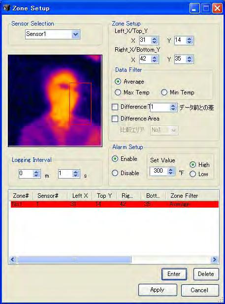
40 Zone Setup The following procedure is used for setting up Zone Trending and the software alarms. [1] Select a sensor number by clicking one of the radio buttons. [1] _[2] [3] [4] [6] Select the sensor. [5] Make sure that you ve registered the IP Address of the connected sensors. [2] Creation of Spots and Zones You can create zones by click and drag with your mouse on the thermal image in the Zone Setup window. The zone can be as big as the full screen and as small as just one pixel. Temperature data value used for trending is a function of the filter asset in step [3]. Click your mouse at the point where you want to start the zone and drag it to the point where you want to finish the zone. The zone will appear as a rectangular with a red boarder on the image screen as shown here. Once the area is specified, the coordinate numbers of Let/Top points and Right/Bottom points are displayed in Zone Setup section. You can also perform fine adjustments of the area coordinates by changing the numbers in these boxes directly. By creating the zone, the coordinates of the zone are displayed. 35
![[3] Zone Data Filter The following choices are available; (1) Average Calculated average value of all the data points in the zone. (2) Max Temp Pixel with the maximum value in the zone.](/docs-images/73/69427439/images/41-0.jpg "(3) Min Temp Pixel with the minimum value in the zone. (4) Difference : Time Trend the temperature difference between the current temperature and the temperature that was taken N times before.")
41 [3] Zone Data Filter The following choices are available; (1) Average Calculated average value of all the data points in the zone. (2) Max Temp Pixel with the maximum value in the zone. (3) Min Temp Pixel with the minimum value in the zone. (4) Difference : Time Trend the temperature difference between the current temperature and the temperature that was taken N times before. (5) Difference : Area Trend the temperature difference between the zone that you are setting now and the zone that you set in Comparing Zone. Zone data filter selection The method of calculating the difference is selected. Zone data filter selection If only one pixel is chosen as a zone, the zone becomes a spot. No data filter is available for a one pixel zone.. [4] Alarm Setup You can setup software alarm set in this section. You can activate the alarm by clicking the radio button of [Enable] and specify the set value for the alarm. You can also choose this alarm to be either a High Alarm or a Low Alarm as described below. (1) High: When the temperature exceeds the set point in the zone, the zone box will flash. (2) Low: When the temperature drops below the set point in the zone, the zone box will flash. Select whether the alarm function is used or not used for selected zone. Select the set point of the alarm in the zone. Make sure that you ve registered the IP Address of the connected sensors. 36
![[5] Registering the Zones By clicking [Enter] button, you can register the zone with all the parameters you have set on [1] through [4] in this window.](/docs-images/73/69427439/images/42-0.jpg "All parameters will be listed in the window as shown below. You can have up to 8 zones and thus you can have up to 8 trending graphs in the Zone Trending window.")
![Click [Enter] button to list parameters in this window The color of the list is corresponding to the line color on the trend screen.](/docs-images/73/69427439/images/42-1.jpg "For adding additional zones, repeat the steps [1] to [5].")
![For deleting the registered zone To delete zones from the list, click the number of the zone you want to delete, then click the [Delete] button. The selected zone is now deleted.](/docs-images/73/69427439/images/42-2.jpg "The following figure is an example of deleting the settings for Zone [No. 2]. Click [Zone#] of the zone you want to delete. In this example, Zone [No. 2] is selected.")
42 [5] Registering the Zones By clicking [Enter] button, you can register the zone with all the parameters you have set on [1] through [4] in this window. All parameters will be listed in the window as shown below. You can have up to 8 zones and thus you can have up to 8 trending graphs in the Zone Trending window. Click [Enter] button to list parameters in this window The color of the list is corresponding to the line color on the trend screen. For adding additional zones, repeat the steps [1] to [5]. For deleting the registered zone To delete zones from the list, click the number of the zone you want to delete, then click the [Delete] button. The selected zone is now deleted. The following figure is an example of deleting the settings for Zone [No. 2]. Click [Zone#] of the zone you want to delete. In this example, Zone [No. 2] is selected. After selecting the zone to delete, click [Delete] button. The selected zone is now deleted from the list. For changing the settings of registered zone To change the parameters of the zone you have registered, perform the steps [1] to [4] again and 37
![click the number of the zone that you want to change, then click [Enter]. The setting information of the zone selected is now modified.](/docs-images/73/69427439/images/43-1.jpg "The following figure is an example for modifying the setting parameters for Zone No. 2. After performing the step [1] ~ [4], click [Zone#] of the zone that you want to change.")
43 click the number of the zone that you want to change, then click [Enter]. The setting information of the zone selected is now modified. The following figure is an example for modifying the setting parameters for Zone No. 2. After performing the step [1] ~ [4], click [Zone#] of the zone that you want to change. In this example, Zone [No. 2] is selected. After selecting the zone for, click [Enter]. The parameter for the zone have been modified. [6] Logging Interval Enter the sample acquisition interval for the trending graph. Data will be plotted at this interval in the trending screen. [7] Start zone data trending. After performing the above steps [1] to [6], click [Apply] button at the bottom of this window. Now, data trending process will start. CAUTION! If you have been logging data, for any zones or spots, if you hit the [Apply] button, the previous zone data will be deleted if you have not saved it. 38

44 The picture shown below is an example Zone Trend window. You can select to either display or not display the zone data by checking the box for that zone. Current temperature value of each zone is also displayed in the current value box., Zone indication check box Current value box Once you have setup the zone corresponding colored zone boxes will appear in the main thermal image window. If you have set software alarms for any of the zones, the zone box will blink when the alarm is activated as shown in the picture below. OSXL-101 Application Software 39
45 4. Help (H) Help Manual is displayed. Version The version information of the application software is shown. 41
![Connection error When there s no communications between the PC and the sensor for 30 seconds, [Connection Error!] is displayed on the main screen.](/docs-images/73/69427439/images/46-0.jpg "The information through the network connection may not be correctly transferred to the under such condition.")
46 Connection error When there s no communications between the PC and the sensor for 30 seconds, [Connection Error!] is displayed on the main screen. The information through the network connection may not be correctly transferred to the under such condition. OSXL-101 Application Software If this happens, check if the LAN Ethernet connector is connected properly. When this type of connection error occurs, both thermal image and trending graph retain the last data that was received from the sensor(s) before the occurrence of the error. OSXL-101 ApplicationSoftware 41
47 Troubleshooting Symptoms Causes Measures Cannot complete software installation No Communications OS version may not be the latest. The custom Network cable is not connected properly. The application software has not been installed. The IP address has not been set. A HUB is in place between PC and the sensor(s). (1) Check whether the HUB has automatic crossing/straight cable converting function. (2) Check the cable being used. Update it to the latest version. Refer to the instruction manual (Page 4) for installation. Check the connection of the cable and Connect the custom network cable properly. Install the application software. Refer to the instruction manual (Page 4). Refer to the instruction manual (Page 16). If the HUB has no automatic crossing/straight converting function, use a crossing/straight converting connector. Refer to the instruction manual for the compact thermal image sensor (Page 2). Indicator lamp is not lit The custom power cable is not connected properly. The power supply has not been turned on. Connect the custom power cable properly. Turn the power supply on. I n d i c a t o r l a m p flashes Red once Internal memory problem Contact to the nearest distributor. I n d i c a t o r l a m p flashes Red twice Abnormal Internal temperature Use the sensor within its operating ambient temperature range. Contact to the nearest distributor. 42
48 WARRANTY/DISCLAIMER OMEGA ENGINEERING, INC. warrants this unit to be free of defects in materials and workmanship for a period of 13 months from date of purchase. OMEGA s WARRANTY adds an additional one (1) month grace period to the normal one (1) year product warranty to cover handling and shipping time. This ensures that OMEGA s customers receive maximum coverage on each product. If the unit malfunctions, it must be returned to the factory for evaluation. OMEGA s Customer Service Department will issue an Authorized Return (AR) number immediately upon phone or written request. Upon examination by OMEGA, if the unit is found to be defective, it will be repaired or replaced at no charge. OMEGA s WARRANTY does not apply to defects resulting from any action of the purchaser, including but not limited to mishandling, improper interfacing, operation outside of design limits, improper repair, or unauthorized modification. This WARRANTY is VOID if the unit shows evidence of having been tampered with or shows evidence of having been damaged as a result of excessive corrosion; or current, heat, moisture or vibration; improper specification; misapplication; misuse or other operating conditions outside of OMEGA s control. Components in which wear is not warranted, include but are not limited to contact points, fuses, and triacs. OMEGA is pleased to offer suggestions on the use of its various products. However, OMEGA neither assumes responsibility for any omissions or errors nor assumes liability for any damages that result from the use of its products in accordance with information provided by OMEGA, either verbal or written. OMEGA warrants only that the parts manufactured by it will be as specified and free of defects. OMEGA MAKES NO OTHER WARRANTIES OR REPRESENTATIONS OF ANY KIND WHATSOEVER, EXPRESS OR IMPLIED, EXCEPT THAT OF TITLE, AND ALL IMPLIED WARRANTIES INCLUDING ANY WARRANTY OF MERCHANTABILITY AND FITNESS FOR A PARTICULAR PURPOSE ARE HEREBY DISCLAIMED. LIMITATION OF LIABILITY: The remedies of purchaser set forth herein are exclusive, and the total liability of OMEGA with respect to this order, whether based on contract, warranty, negligence, indemnification, strict liability or otherwise, shall not exceed the purchase price of the component upon which liability is based. In no event shall OMEGA be liable for consequential, incidental or special damages. CONDITIONS: Equipment sold by OMEGA is not intended to be used, nor shall it be used: (1) as a Basic Component under 10 CFR 21 (NRC), used in or with any nuclear installation or activity; or (2) in medical applications or used on humans. Should any Product(s) be used in or with any nuclear installation or activity, medical application, used on humans, or misused in any way, OMEGA assumes no responsibility as set forth in our basic WARRANTY/ DISCLAIMER language, and, additionally, purchaser will indemnify OMEGA and hold OMEGA harmless from any liability or damage whatsoever arising out of the use of the Product(s) in such a manner. RETURN REQUESTS/INQUIRIES Direct all warranty and repair requests/inquiries to the OMEGA Customer Service Department. BEFORE RETURNING ANY PRODUCT(S) TO OMEGA, PURCHASER MUST OBTAIN AN AUTHORIZED RETURN (AR) NUMBER FROM OMEGA S CUSTOMER SERVICE DEPARTMENT (IN ORDER TO AVOID PROCESSING DELAYS). The assigned AR number should then be marked on the outside of the return package and on any correspondence. The purchaser is responsible for shipping charges, freight, insurance and proper packaging to prevent breakage in transit. FOR WARRANTY RETURNS, please have the following information available BEFORE contacting OMEGA: 1. Purchase Order number under which the product was PURCHASED, 2. Model and serial number of the product under warranty, and 3. Repair instructions and/or specific problems relative to the product. FOR NON-WARRANTY REPAIRS, consult OMEGA for current repair charges. Have the following information available BEFORE contacting OMEGA: 1. Purchase Order number to cover the COST of the repair, 2. Model and serial number of the product, and 3. Repair instructions and/or specific problems relative to the product. OMEGA s policy is to make running changes, not model changes, whenever an improvement is possible. This affords our customers the latest in technology and engineering. OMEGA is a registered trademark of OMEGA ENGINEERING, INC. Copyright 2009 OMEGA ENGINEERING, INC. All rights reserved. This document may not be copied, photocopied, reproduced, translated, or reduced to any electronic medium or machine-readable form, in whole or in part, without the prior written consent of OMEGA ENGINEERING, INC.
OM-CP-Cryo-Temp Ultra Low Temperature Data Logger. Shop online at. omega.com For latest product manuals: omegamanual.
 MADE IN Shop online at omega.com e-mail: info@omega.com For latest product manuals: omegamanual.info OM-CP-Cryo-Temp Ultra Low Temperature Data Logger OM-CP-Cryo-Temp Product Notes Manual Start When the
User s Guide. Shop online at. Made in China. Two-wire Display and Control Unit
 Made in China User s Guide Two-wire Display and Control Unit Shop online at omega.com e-mail: info@omega.com For latest product manuals: omegamanual.info Manual for 2-wire LCD display and control unit
LVCN-302 Set-Up Manual for Sump Model
 omega.com LVCN302 SetUp Manual for Sump Model User s Guide MADE IN Specifications: : Isolated input accepts any type of 420 ma process signal. Loop power available up to 24VDC for 2 wire device Input Power:
User s Guide. OSXL685 and OSXL689. High Performance Infrared Thermometer. Shop online at
 User s Guide Shop online at omega.com e-mail: info@omega.com For latest product manuals: omegamanual.info TM WITH BUILT-IN PATENTED LASER CIRCLE SIGHTING OSXL685 and OSXL689 High Performance Infrared Thermometer
User s Guide HHAQ-109. Portable Multi-gas Detector. Shop online at omega.com SM
 User s Guide Shop online at omega.com SM e-mail: info@omega.com For latest product manuals: www.omegamanual.info HHAQ-109 Portable Multi-gas Detector User Guide Thanks for our using our products. Before
User s Guide. Setpoint Option Card. Shop online at. omega.com For latest product manuals: omegamanual.
 User s Guide Shop online at omega.com e-mail: info@omega.com For latest product manuals: omegamanual.info LDP6-CDS Setpoint Option Card LP0683X OMEGAnet Online Service omega.com Internet e-mail info@omega.com
User s Guide OS210-C4. IR Temperature Sensors. Shop online at omega.com. For latest product manuals: omegamanual.
 User s Guide Shop online at omega.com e-mail: info@omega.com For latest product manuals: omegamanual.info MADE IN UNITED KINGDOM OS210-C4 IR Temperature Sensors OMEGAnet Online Service omega.com Internet
Supervisor Standard Edition
 Supervisor Standard Edition Installation Manual Heat-Tracing Controller Configuration and Monitoring Software INSTALL-119 (Europe) 1 / 18 Contents Section 1 Introduction...3 1.1 Welcome...3 1.2 Vital Information...3
Alarm Client. Installation and User Guide. NEC NEC Corporation. May 2009 NDA-30364, Revision 9
 Alarm Client Installation and User Guide NEC NEC Corporation May 2009 NDA-30364, Revision 9 Liability Disclaimer NEC Corporation reserves the right to change the specifications, functions, or features,
User s Guide. LVU-800, & LV U Ultrasonic Level System
 M-2051 1/22/02 1:03 PM Page 2 W h e re Do I Find Everything I Need for P rocess Measurement and Control? OMEGA Of Course! Shop online at www.omega.com T E M P E R AT U R E Thermocouple, RTD & Thermistor
IndigoVision Alarm Panel. User Guide
 IndigoVision Alarm Panel User Guide THIS MANUAL WAS CREATED ON 2/21/2017. DOCUMENT ID: IU-AP-MAN002-4 Legal considerations LAWS THAT CAN VARY FROM COUNTRY TO COUNTRY MAY PROHIBIT CAMERA SURVEILLANCE. PLEASE
User s Guide. DPF-520 Series XXXXXX. Shop online at. omega.com For latest product manuals: omegamanual.info
 User s Guide Shop online at omega.com e-mail: info@omega.com For latest product manuals: omegamanual.info XXXXXX DPF-520 Series Xxxxx Flow Xxxxxxxx Computer OMEGAnet Online Service omega.com Internet e-mail
JOVY SYSTEMS RE User Manual Rev. 1.00
 JOVY SYSTEMS RE-7550 User Manual Rev. 1.00 Index - Introduction... 3 - Copyrights and Liability disclaimer........ 3 - Specifications.. 4 - Safety/ Caution instructions....... 4 - RE-7550 hardware description......
AUTOMATION. Operator s Manual RST Series Web Enabled Input Module. Rev. A2, 1/12
 AUTOMATION P R O D U C T S GROUP, INC. Operator s Manual RST-5000 Series Web Enabled Input Module Rev. A2, 1/12 Tel: 1/888/525-7300 Fax: 1/435/753-7490 www.apgsensors.com E-mail: sales@apgsensors.com RST-5000
Notice... 1 Trademarks... 1 US Patent Numbers... 1 Technical Services Contact Information... 2 Document Conventions... 2 Warranty...
 Table of Contents Preface 1 Notice... 1 Trademarks... 1 US Patent Numbers... 1 Technical Services Contact Information... 2 Document Conventions... 2 Warranty... 2 Chapter 1 Radius Overview 6 1.1 About
3820, 3820i, 4820, 4820i
 3820, 3820i, 4820, 4820i Cordless Imaging Systems Quick Start Guide Note: Refer to your user s guide for information about cleaning your device. For localized language versions of this document, go to
USER MANUAL DexTempTM 1000 Temperature Monitor (P/N: IR-1001) DexTempTM 1000 USB Non-Contact Temperature Monitor. User Manual.
 DexTempTM 1000 USB Non-Contact Temperature Monitor. User Manual.") USER MANUAL DexTempTM 1000 Temperature Monitor (P/N: IR-1001) DexTempTM 1000 USB Non-Contact Temperature Monitor User Manual 8690 Rev B Update: 10/24/2013 1 Table of Contents 1 Introduction.. 3 2 Host
USER MANUAL DexTempTM 1000 Temperature Monitor (P/N: IR-1001) DexTempTM 1000 USB Non-Contact Temperature Monitor User Manual 8690 Rev B Update: 10/24/2013 1 Table of Contents 1 Introduction.. 3 2 Host
User s Guide. CN606 / 612 AC Series & CN606 / 612 DC Series CONTRONAUTICS INCORPORATED. Table of Contents.
 User s Guide SECTION Table of Contents Page SECTION 1 INTRODUCTION............ 2 1.1 Description...................... 2 1.2 Features........................ 2 1.3 Models........................ 3 SECTION
CompleteView Alarm Client User Manual. CompleteView Version 4.6.1
 CompleteView Alarm Client User Manual CompleteView Version 4.6.1 Table of Contents Introduction... 1 Overview...2 System Requirements...2 Configuration... 3 Starting the Alarm Client...3 Menus...3 File
Before you install ProSeries Express Edition software for network use
 Before you install ProSeries Express Edition software for network use The following pages describe system requirements and other information you need to know before installing ProSeries Express Edition
Avigilon Control Center 5 System Integration Guide
 Avigilon Control Center 5 System Integration Guide for Paxton Net2 Access Control Systems 2014 Avigilon Corporation. All rights reserved. Unless expressly granted in writing, no license is granted with
User Manual. Humidity-Temperature Chart Recorder. Model RH520
 User Manual Humidity-Temperature Chart Recorder Model RH520 Introduction Congratulations on your purchase of the Extech RH520 Temperature + Humidity Chart Recorder. The RH520 measures and displays Temperature,
Avigilon Control Center System Integration Guide
 Avigilon Control Center System Integration Guide with Velocity INT-HIRSCH-A-Rev3 Copyright 2013 Avigilon. All rights reserved. No copying, distribution, publication, modification, or incorporation of this
Simplex Panel Interface Guide
 Simplex Panel Interface Guide February 2016 SATEON Software Integrations Simplex Panel Interface Guide Issue 1.0, released February 2016 Disclaimer Copyright 2016, Grosvenor Technology. All rights reserved.
HikCentral Web Client. User Manual
 HikCentral Web Client User Manual Legal Information User Manual 2018 Hangzhou Hikvision Digital Technology Co., Ltd. About this Manual This Manual is subject to domestic and international copyright protection.
Installation, Configuration and User Manual
 Model 8826 System Controller Model 8826 System Controller Installation, Configuration and User Manual READ AND SAVE THESE INSTRUCTIONS WELCOME Thank you for choosing the Aprilaire HVAC Automation System.
iminiplus PDF User Guide Version 2.0
 iminiplus PDF User Guide Version 2.0 Table of contents 1 Scope of this document... 3 2 Why PDF?... 3 3 Logger profile... 3 4 What you need to get started... 4 5 FDA 21 CFR Part 11 compliance... 5 6 How
Milestone SMI Intrepid II Perimeter Module 1.1 User s Manual
 Milestone SMI Intrepid II Perimeter Module 1.1 User s Manual Target Audience for this Document This document is aimed at system users and provides descriptions on how to install and maintain the Milestone
Operation Manual Fighter ProVision Software. Version: 0.0 Revision: 1
 Operation Manual Fighter ProVision Software Version: 0.0 Revision: 1 TABLE OF CONTENTS 1. Introduction 5 2. Software Installation 5 3. PC Users 6 3.1 Introduction 6 3.2 Default Code 6 3.3 Edit PC User
Mark 25 Ultrapure Water Conductivity Analyzer
 Martek Instruments, Inc. Mark 25 Ultrapure Water Conductivity Analyzer Instruction Manual WARRANTY POLICY Unless otherwise stated, MARTEK INSTRUMENTS, INC. warrants this equipment to be free from defects
Alarm Coordination Connected Components Building Block. Quick Start
 Alarm Coordination Connected Components Building Block Quick Start Important User Information Solid state equipment has operational characteristics differing from those of electromechanical equipment.
User s Guide TOTE SERIES. Wrap-Around Tote Tank Headers. TOTE SERIES Wrap-Around Tote Tank Heaters. Shop online at omega.com
 TM TABLE OF CONTENTS User s Guide Introduction... 2 Applications... 2 Approvals... 2 Important Safety Instructions... 3 General Specifications... 4 Installation / Operating Instructions... 5 Emergency
HikCentral Web Client. User Manual
 HikCentral Web Client User Manual Legal Information User Manual 2018 Hangzhou Hikvision Digital Technology Co., Ltd. About this Manual This Manual is subject to domestic and international copyright protection.
Oracle Communications Performance Intelligence Center
 Oracle Communications Performance Intelligence Center System Alarms Guide Release 10.2.1 E77506-01 June 2017 1 Oracle Communications Performance Intelligence Center System Alarms Guide, Release 10.2.1
Recording Server PRELOADED
 Configuration English Recording Server PRELOADED Rev. 1.1.2 / 2015-12-09 Module BANK Information about copyright, trademarks, design patents 2015 Dallmeier electronic The reproduction, distribution and
Dolphin 9900 Mobile Computer
 Dolphin 9900 Mobile Computer with Windows Mobile 6 Quick Start Guide Dolphin 9900 Quick Start Guide Out of the Box Verify that the box contains the following items: Dolphin 9900 mobile computer (the terminal)
Welcome to MultiSight TM Vision Sensor Hands-On Lab
 Welcome to MultiSight TM Vision Sensor Hands-On Lab About This Hands-On Lab Welcome to the MultiSight TM Vision Sensor Hands-On Lab! This session provides you with an opportunity to explore the functionality
Operating & Maintenance Manual. Alert-4 Ethernet LCD Master Alarm
 Operating & Maintenance Manual Alert-4 Ethernet LCD Master Alarm w w w. a m i c o. c o m Contents User Responsibility 4 Introduction 4 Features 5 Description of the Alarm 5 Shipment Details 5 The Alarm
User s Guide. FLSW Series ROTAMETER WITH ALARM. Shop online at omega.com. For latest product manuals:
 TM User s Guide Shop online at omega.com e-mail: info@omega.com For latest product manuals: www.omegamanual.info FLSW Series ROTAMETER WITH ALARM omega.com info@omega.com U.S.A. Headquarters: Servicing
Sintrol Snifter A2 EX. Manual. Version 1.2.3
 Sintrol Snifter A2 EX Manual Version 1.2.3 Table of Contents 1 INTRODUCTION... 3 1.1 Safety... 3 1.2 Product overview... 4 1.3 How does it work?... 4 2 INSTALLATION... 4 2.1 Selecting the installation
CWR265SZ 26 Bottle Built-in Wine Cooler Owner s Manual
 CWR265SZ 26 Bottle Built-in Wine Cooler Owner s Manual This owner s manual provides instructions on safe installation use, and troubleshooting assistance. Please read it carefully and save it for reference
Avigilon Control Center System Integration Guide
 Avigilon Control Center System Integration Guide with Picture Perfect 4 INT-PP4-A-Rev1 Copyright 2012 Avigilon. All rights reserved. No copying, distribution, publication, modification, or incorporation
USER MANUAL. ITAG 4 / ITAG 4 Bio/ ITAG 4 TH DATA LOGGER. UM-ITAG REV.B 03/02/2016
 USER MANUAL EN ITAG 4 / ITAG 4 Bio/ ITAG 4 TH DATA LOGGER Updated@ 03/02/2016 CONTENTS Product Overview... 3 Logger... 3 LCD... 4 Technical Specifications... 5 TEMPCENTRE SOFTWARE... 6 How to download
User s Guide OS137 SERIES. Miniature Non-Contact Infrared Temperature Sensor/Transmitter. Shop online at omega.com
 CAUTION! This product is not intended for medical use or use on humans User s Guide Shop online at omega.com e-mail: info@omega.com For latest product manuals: omegamanual.info OS137 SERIES Miniature Non-Contact
Dashboard for Windows V1.1.0
 User manual Dashboard for Windows V1.1.0 TBS Electronics BV De Factorij 46 1689 AL Zwaag The Netherlands www.tbs-electronics.com COPYRIGHT 2009 (rev1e) - 1 - TABLE OF CONTENTS 1. INTRODUCTION......................
IndigoVision. GAI-Tronics Integration Module. Administrator's Guide
 IndigoVision GAI-Tronics Integration Module Administrator's Guide GAI-Tronics Integration Module THIS MANUAL WAS CREATED ON 10 APRIL 2013. DOCUMENT ID: IU-IM-MAN019-1 Legal Considerations LAWS THAT CAN
Installing ProSeries software for stand-alone use
 Welcome to ProSeries tax software For information about this topic... Look here... Getting ready Page 1 Installing ProSeries software for stand-alone use Page 1 Setting up the ProSeries program Page 3
Avigilon Control Center 5 System Integration Guide
 Avigilon Control Center 5 System Integration Guide with Hirsch Velocity INT-HIRSCH-B-Rev1 2012 2014 Avigilon Corporation. All rights reserved. Unless expressly granted in writing, no license is granted
Figure 1. Proper Method of Holding the ToolStick. Figure 2. Improper Method of Holding the ToolStick
 CAN OBD READER REFERENCE DESIGN KIT USER GUIDE 1. Standard ToolStick Handling Recommendations The ToolStick Base Adapter and daughter cards are distributed without any protective plastics. To prevent damage
MPL3115A2 Sensor Toolbox User s Guide
 Freescale Semiconductor Document Number: MPL3115A2STUG User s Guide Rev. 0, 04/2012 MPL3115A2 Sensor Toolbox User s Guide 1 Introduction The Freescale DEMOSTBMPL3115A2 Sensor Toolbox provides the hardware
Owner s Manual. PIR-1 IR Learner
 Owner s Manual PIR-1 IR Learner PIR-1 Owner s Manual 2010-2013 Universal Remote Control, Inc. The information in this owner s manual is copyright protected. No part of this manual may be copied or reproduced
OMEGA (MODEL:610LF) OS642F-LS Infrared Thermometer With Laser Marker
 OS642F-LS Infrared Thermometer With Laser Marker") OMEGA (MODEL:610LF) OS642F-LS Infrared Thermometer With Laser Marker omega.com TM OMEGAnet SM On-Line Service http://www.omega.com Internet e-mail info@omega.com Servicing North America: USA: ISO 9001
OMEGA (MODEL:610LF) OS642F-LS Infrared Thermometer With Laser Marker omega.com TM OMEGAnet SM On-Line Service http://www.omega.com Internet e-mail info@omega.com Servicing North America: USA: ISO 9001
LDP-124 AND LDP-144 SERIES FOR TEMPERATURE
 User's Guide http://www.omega.com e-mail: info @omega.com LDP-124 AND LDP-144 SERIES FOR TEMPERATURE OMEGAnet On-Line Service http://www.omega.com Internet e-mail info@omega.com Servicing North America:
Installation and Operations Manual
 Installation and Operations Manual H-IM-LLC February 2018 Part No. 25092501 Replaces H-IM-LLC (01/2014) Lead Lag Control System Table of Contents General Safety Information 2 Inspection 2 Warranty Statement
MODEL 5100 BROADBAND ALARM COMMUNICATOR INSTALLATION & USER S GUIDE PRODUCT ID #
 MODEL 5100 BROADBAND ALARM COMMUNICATOR INSTALLATION & USER S GUIDE PRODUCT ID # 19-25133-502 MODEL 5100 2011 Uplink Security LLC. All rights reserved. No part of this publication may be reproduced or
Falcon-II Next Generation, Air Quality Monitor CO2 & Temperature
 Critical Environment Technologies Canada Inc. Falcon-II Next Generation, Air Quality Monitor CO2 & Temperature OPERATION MANUAL REV: A JUNE-2-2008 #145, 7391 Vantage Way Delta, BC V4G 1M3 Canada Phone:
Ademco Vista Alarm Panel
 System Galaxy Quick Guide CONFIGURATION AND OPERATION Ademco Vista Alarm Panel JAN 2018 SG 10.5.6 System Galaxy Quick Guide For Ademco Vista Panel Configuration & Operation 2nd edition JAN 2018 Information
LineGuard 2300 Program User Manual (FloBoss 107)
") Form A6251 Part Number D301346X012 November 2012 LineGuard 2300 Program User Manual (FloBoss 107) Remote Automation Solutions Revision Tracking Sheet November 2012 This manual may be revised periodically
Form A6251 Part Number D301346X012 November 2012 LineGuard 2300 Program User Manual (FloBoss 107) Remote Automation Solutions Revision Tracking Sheet November 2012 This manual may be revised periodically
AK-CS On Board Guide
 MAKING MODERN LIVING POSSIBLE AK-CS On Board Guide electronic controls & sensors About this guide The AK-CS On Board guide highlights the use of the RMT tool, allowing remote software management. Consult
VMD Guide for MP-980 Cameras
 Configuration Guide XX206-10-01 VMD Guide for MP-980 Cameras Vicon Industries Inc., 89 Arkay Drive, Hauppauge, New York 11788 Tel: 631-952-2288 Fax: 631-951-2288 Toll Free: 800-645-9116 24-Hour Technical
User Manual. Dryer Controller M720
 User Manual Dryer Controller M720 Hardware version 1.00 Software version 1.00 Preliminary version Manual M720 Dryer controller Page 1 of 42 Document history Preliminary version: - Created in April, 2009
Avigilon System Integration Guide. Avigilon Control Center with AMAG Symmetry Security Management System 7.0
 Avigilon System Integration Guide Avigilon Control Center with AMAG Symmetry Security Management System 7.0 2013-2016, Avigilon Corporation. All rights reserved. AVIGILON, the AVIGILON logo, HDSM, HIGH
VS2000V Veterinary Vital Signs Monitor Operation Manual
 VS2000V Veterinary Vital Signs Monitor Operation Manual - English Version 1.0, July 2011 2011 UTECH Co., Ltd. All rights reserved. Table of Contents Table of Contents Warranty and Service Information...
Instruction manual MTL process alarm equipment. October 2016 CSM 725B rev 2 MTL RTK 725B. Configuration Software Manual
 Instruction manual MTL process alarm equipment October 2016 CSM 725B rev 2 MTL RTK 725B Configuration Software Manual SECTION 1 - INTRODUCTION... 5 Basic Requirements... 5 SECTION 2 - SOFTWARE INSTALLATION...
D-TECT 3 IP. GJD260 IP Motion Detector
 D-TECT 3 IP GJD260 IP Motion Detector PACKAGE CONTENTS 1 x D-TECT 3 IP 1 x Drilling template for fixing holes 3 x 31.75mm wall plugs 3 x 31.75mm screws 2 x Spare sliding curtains 2 x Tamper feet 1 x Tamper
Avigilon Control Center System Integration Guide
 Avigilon Control Center System Integration Guide with Gallagher Command Centre INT-CARDAX-C-Rev3 Copyright 2013 Avigilon. All rights reserved. No copying, distribution, publication, modification, or incorporation
PWM. Solar Charge controller with Ethernet. Solar Smart PWM 20Amp. Hardware Description : Release : 19 June 2014
 Solar Charge controller with Ethernet Release : 19 June 2014 Hardware Version : Version 1 Firmware version 1 PC Application Software : Version 1.0.0.0 Hardware Description : The Solar Smart regulator was
Accessories for SMA Inverters Fan Retrofit Kit FANKIT02-10
 Accessories for SMA Inverters Fan Retrofit Kit FANKIT02-10 Installation Manual FANKIT02-IA-US_en-10 IMUS-FANK-TL21 Version 1.0 CA US SMA America, LLC Legal Restrictions Legal Restrictions Copyright 2013
Chapter 6. Alarm History Screen. Otasuke GP-EX! Chapter 6 Alarm History Screen 6-0. Alarm History Screen 6-1. Display Alarm History in List 6-2
 Chapter 6 Alarm History Screen Alarm History Screen 6- Display Alarm History in List 6-2 Let s Display Alarm History. 6-3 Read Data when Alarms Occur 6-2 Let s Read Data when Alarm Occur. 6-3 Let s Edit
Series: MBC1-TC Mini Benchtop Temperature Controller
 User s Guide Series: MBC1-TC Mini Benchtop Temperature Controller Imagine Instruments LLC:: 4500 Williams Drive, Ste 212-318 :: Georgetown, TX 78633 :: p. 855.574.6243 e-mail: info@imagineinstruments.com
User s Guide. Shop online at. omega.com CN Chromalox Rev Set Point. Load. Alarm.
 User s Guide Chromalox Alarm Temp Set Point 2110 F C Shop online at omega.com www.omega.com e-mail: info@omega.com Set Point CN2110 0037-75429 Rev. 8-03 Omega omega.com OMEGAnet Online Service www.omega.com
IntelliDoX Operator Manual
 IntelliDoX Operator Manual OPERATOR MANUAL TABLE OF CONTENTS Table of Contents Table of Contents...1 About this Publication...3 Important Safety Information: Read First...4 Getting Started...5 About the
VMD Guide for V960 Series Cameras
 Configuration Guide XX206-40-01 VMD Guide for V960 Series Cameras Vicon Industries Inc., 89 Arkay Drive, Hauppauge, New York 11788 Tel: 631-952-2288 Fax: 631-951-2288 Toll Free: 800-645-9116 24-Hour Technical
Dryer Controller M720
 User Manual Dryer Controller M720 Hardware version 2.00 Software version 2.00 Manual M720 Dryer controller Page 1 of 60 Document history Preliminary version: - Created in April, 2009 Hardware Version 2.00,
INSTALLER S & OWNER S MANUAL
 INSTALLER S & OWNER S MANUAL HVAC INSTALLER: PLEASE LEAVE MANUAL FOR HOMEOWNER Part No. 4028539 Dehumidifier & Ventilation System Controller 4201 Lien Rd Madison, WI 53704 TOLL-FREE 1-800-533-7533 www.thermastor.com
Ion Gateway Cellular Gateway and Wireless Sensors
 Page 1 of 9 Account & Network Setup If this is your first time using the Ion Gateway online system site you will need to create a new account. If you have already created an account you can skip to the
Milestone XProtect. Central 3.7 User s Manual
 Milestone XProtect Central 3.7 User s Manual Target Audience for this Document This document is intended for end users of the Milestone XProtect Central surveillance system monitoring solution, such as
PowerRouter application guideline
 PowerRouter application guideline Software installation tool - version 3.4 Before operating the PowerRouter, you may initialize the PowerRouter by using the PowerRouter software installation tool. The
Avigilon System Integration Guide. for the Avigilon Control Center and Access Control Manager
 Avigilon System Integration Guide for the Avigilon Control Center and Access Control Manager 2014-2017, Avigilon Corporation. All rights reserved. AVIGILON, the AVIGILON logo, ACC, AVIGILON CONTROL CENTER,
INSTRUCTION MANUAL P Heating and 1 Cooling
 REPLACEMENT COMPONENTS DIVISION CARRIER CORPORATION www.totaltouch.info Technical Support: 1-866-90TOUCH (1-866-908-6824) INSTRUCTION MANUAL P286-1200 2 Heating and 1 Cooling Physical Dimensions Case:
Accessories for SMA Inverters Fan Retrofit Kit FANKIT02-10
 Accessories for SMA Inverters Fan Retrofit Kit FANKIT02-10 Installation Manual FANKIT02-IA-US_en-12 Version 1.2 CA US SMA America, LLC Legal Restrictions Legal Restrictions Copyright 2014 SMA America,
OMEGA. OS643E-LS/OS643E Infrared Thermometer With Laser Sighting
 OMEGA OS643E-LS/OS643E Infrared Thermometer With Laser Sighting omega.com TM OMEGAnet SM On-Line Service http://www.omega.com Internet e-mail info@omega.com Servicing North America: USA: ISO 9001 Certified
Installation Manual WARNING. Add-on Controller Installation Kit NPE-180A/210A/240A
 Installation Manual Add-on Controller Installation Kit NPE-180A/210A/240A This device is designed to work with NPE-180A/210A/240A water heaters ONLY. WARNING All Installations should be done only by a
Diagnostics and Monitoring System WEB Tool 2. User Manual
 Diagnostics and Monitoring System 2 (Translation of the original documentation) User Manual S/N: Valid from: 01.05.2012 Rev.: 2.0 2 Rev. 1.... 1 1.1 General information... 1 1.1.1 Equipment... 1 1.1.2
Added password for IP setup page : Password must be in IP format!
 NETWORK POWER MONITOR Release : 21 August 2014 Hardware Version : Version 7 Firmware version 1.00 PC Application Software : Version (latest)...2 Added password for IP setup page : Password must be in IP
ModSync Sequencing System Installation & Operation Manual. For use with Fulton Steam Boilers.
 ModSync Sequencing System Installation & Operation Manual For use with Fulton Steam Boilers. Revision 3.0 8/21/2008 - 2 - Table of Contents Introduction Page 4 Features Page 4 Sequence of Operation Page
E N G L I S H FIRE ALARM ASPIRATION SENSING TECHNOLOGY QUICK INSTALLATION GUIDE STAND-ALONE FAAST LT MODELS FL0111E FL0112E FL0122E. 367 mm.
 E N G L I S H FIRE ALARM ASPIRATION SENSING TECHNOLOGY QUICK INSTALLATION GUIDE STAND-ALONE FAAST LT MODELS FL0E FL0E FL0E mm mm 0 mm DESCRIPTION The LT FL0 Series is part of the Fire Alarm Aspiration
Static Pressure Control
 The (model SPC-2) is a fully programmable controller that provides extensive flexibility for your curtain or awning control needs. The SPC-2 automatically controls the pressure in a room by operating a
INSTALLER S & OWNER S MANUAL
 INSTALLER S & OWNER S MANUAL HVAC INSTALLER: PLEASE LEAVE MANUAL FOR HOMEOWNER DEH 3000R Part No. 4028407 Dehumidifier & Ventilation System Controller 4201 Lien Road, Madison, WI 53704 TOLL-FREE (800)-533-7533
2-Port alarmcharge Hub - Manual
 Installation Manual 1. What s in the box 2. Fixture preparation 3. Mounting 4. Mechanical 5. Device power Operation Manual 6. Device connectors and connections 7. Alarming remote control 8. Safety 9. Warranty
Protégé Eclipse LED Keypad User Manual PRT-KLES
 Protégé Eclipse LED Keypad User Manual PRT-KLES The specifications and descriptions of products and services contained in this manual were correct at the time of printing. Integrated Control Technology
UNC100 Integra Manual
 UNC100 Integra Manual New Generation Building Security July 30, 2014 V1.2 Copyright Notice Copyright 1995-2014 by All rights reserved Worldwide. Printed in Canada. This publication has been provided pursuant
ATMOX MAXX System THE Complete Moisture Control System for Crawlspaces. User s Guide
 ATMOX MAXX System THE Complete Moisture Control System for Crawlspaces User s Guide Welcome to ATMOX This User s Guide will cover the basic operation of the ATMOX System. For instructions on installation,
Centroid Snet 2. Battery Management Software. User Manual V1.1. Eagle Eye Power Solutions, LLC Keeping an Eye on Your Critical Power!
 Eagle Eye Power Solutions, LLC Keeping an Eye on Your Critical Power! Centroid Snet 2 Battery Management Software User Manual V1.1 www.eepowersolutions.com Tel: 1-877-805-3377 info@eepowersolutions.com
Trident User s Manual
 Labkotec Oy Myllyhaantie 6 33960 Pirkkala FINLAND Tel. +358 (0)29 006 260 18.05.2017 Fax +358 (0)29 006 1260 Internet: www.labkotec.fi 34 pages Trident Copyright 2017 Labkotec Oy 1/34 TABLE OF CONTENTS
Before you install ProSeries software for network use
 Before you install ProSeries software for network use The following pages describe system requirements and other information you need to know before installing ProSeries software for network use. Important:
External Wireless Sounder
 External Wireless Sounder Model: WL RWS401 Installation and Programming Instructions Table of Contents Introduction... 3 Operational Functions... 3 Alarm / Tamper Indication... 3 Low Battery Indication...
Because you re not like everyone else. PORTABLE CLEAR ICE MAKER IM200SS OWNER S MANUAL. Manual v1.0
 Because you re not like everyone else. PORTABLE CLEAR ICE MAKER IM200SS OWNER S MANUAL Manual v1.0 2 BECAUSE YOU RE NOT LIKE EVERYONE ELSE And neither are we. Always at the forefront of our industry, our
Q-tag CLm doc family Type: doc / doc L / doc LR / doc D
 Q-tag CLm doc family Type: doc / doc L / doc LR / doc D Q-tag CLm doc The clever one Q-tag CLm doc LR The profitable one Q-tag CLm doc L The durable one Q-tag CLm doc D The cool one To monitor your transport
Patriot Systems Limited
 COPYRIGHT 1997 - The Patriot Systems Ltd. Patriot Alarm Monitoring Automation Package is licensed for use on one computer, by the original person, or company, or organisation whose name is registered with