ABB. The Company. Electrical Safety. Symbols EN ISO 9001:2000
|
|
|
- Dominic Goodman
- 6 years ago
- Views:
Transcription

1
2 ABB The Company We are an established world force in the design and manufacture of instrumentation for industrial process control, flow measurement, gas and liquid analysis and environmental applications. As a part of ABB, a world leader in process automation technology, we offer customers application expertise, service and support worldwide. We are committed to teamwork, high quality manufacturing, advanced technology and unrivalled service and support. The quality, accuracy and performance of the Company s products result from over 100 years experience, combined with a continuous program of innovative design and development to incorporate the latest technology. The UKAS Calibration Laboratory No is just one of the ten flow calibration plants operated by the Company, and is indicative of our dedication to quality and accuracy. EN ISO 9001:2000 RE GISTERED Cert. No. Q5907 EN (ISO 9001) Lenno, Italy Cert. No. 9/90A Electrical Safety This equipment complies with the requirements of CEI/IEC : 'Safety Requirements for Electrical Equipment for Measurement, Control and Laboratory Use'. If the equipment is used in a manner NOT specified by the Company, the protection provided by the equipment may be impaired. Symbols One or more of the following symbols may appear on the equipment labelling: Warning Refer to the manual for instructions Direct current supply only Caution Risk of electric shock Alternating current supply only Protective earth (ground) terminal Earth (ground) terminal Both direct and alternating current supply The equipment is protected through double insulation Information in this manual is intended only to assist our customers in the efficient operation of our equipment. Use of this manual for any other purpose is specifically prohibited and its contents are not to be reproduced in full or part without prior approval of the Technical Communications Department. Health and Safety To ensure that our products are safe and without risk to health, the following points must be noted: 1. The relevant sections of these instructions must be read carefully before proceeding. 2. Warning labels on containers and packages must be observed. 3. Installation, operation, maintenance and servicing must only be carried out by suitably trained personnel and in accordance with the information given. 4. Normal safety precautions must be taken to avoid the possibility of an accident occurring when operating in conditions of high pressure and/or temperature. 5. Chemicals must be stored away from heat, protected from temperature extremes and powders kept dry. Normal safe handling procedures must be used. 6. When disposing of chemicals ensure that no two chemicals are mixed. Safety advice concerning the use of the equipment described in this manual or any relevant hazard data sheets (where applicable) may be obtained from the Company address on the back cover, together with servicing and spares information.
3 GETTING STARTED The COMMANDER 320 Booster Pump Controller acts as a differential pressure switch for use in the regeneration section of a pasteurizer. If the difference between pasteurized milk pressure and raw milk pressure falls below a preset level, the controller shuts down the raw milk booster pump or alternatively, channels the pasteurized milk into the divert flow. The COMMANDER 320 has the following features: Two 4 to 20mA analog inputs. A transmitter power supply capable of powering the raw and pasteurized 2-wire pressure transmitters. A digital display of the raw and pasteurized product pressures. A bargraph display of the difference between the raw and pasteurized pressures. A deviation alarm to detect when the difference between the raw and pasteurized pressures falls below a preset minimum. A start-up alarm which allows the booster pump to remain off until the normal system operating back pressure is achieved. A manual override facility which allows the booster pump to be turned off using a digital input. Selectable pressure differential retransmission output. Three relay outputs: two for booster pump or divert valve control, one to operate a warning light or horn. This manual is divided into 4 sections and contains all the information necessary to install, configure and operate the instrument. Displays and Function Keys Displays and function keys LED Indication Error Messages Operating Level Operating Page Operating Page Messages Alarm Acknowledge Page Security Access Configuration Level Set Up Alarms Set Up Inputs Set Up Display Scale Adjustment Security Code Set Up Commissioning Installation Siting Mounting Electrical connections Symbol Identification and Contents of Sections 1
4 CONTENTS Section Page 1 DISPLAYS AND CONTROLS Introduction Use of Controls Displays and LED Indicators LED Indications, Relay and Alarm States Deviation Bargraph Instrument Power-up OPERATING LEVEL Operating Page Operating Page Messages Alarm Acknowledge Page Security Access Security Code Page CONFIGURATION LEVEL Preparation for Changes to the Parameters Set Up Alarms Page Set Up Inputs Set Up Display Page Retransmission Output Page Scale Adjustment Page Access Page Commissioning INSTALLATION Checking the Code Number Siting Mounting Access to Terminals Setting the Input Selector Links Setting the Isolated Output Link Cable Glands and Conduit Fixings Cable Glands (IEC 20mm) Conduit Adaptors (N. American 0.5in) Cable Glands (N. American 0.5in) Connections Summary Input Connections Current Input wire Transmitter Output Connections Logic Input Connection Relay Connections Power Supply Selection and AC Connections...31 SPECIFICATION
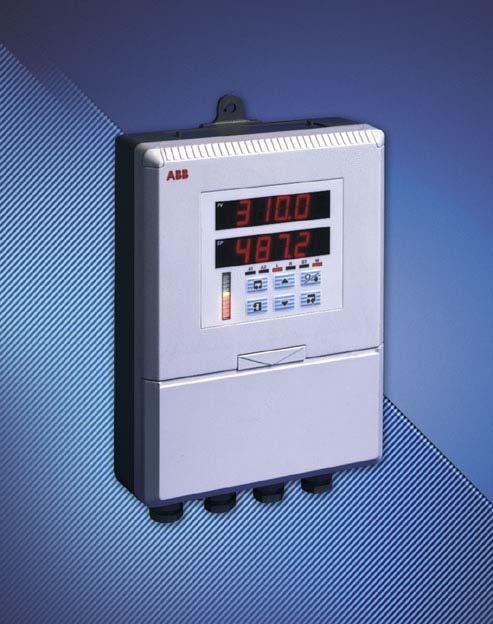
5 1 DISPLAYS AND CONTROLS 1.1 Introduction Fig. 1.1 The Commander 320 front panel display, function keys and LED indicators are shown in Fig. 1.1 RAW 'Enter' Switch LED Displays PAS LED Indicators Deviation Bar Graph Display A1 A2 BP1 BP2 Controls Refer to Figs. 1.2 to 1.6 'Data Entry' Switch (use to enter settings and values in frames) Fig. 1.1 Front Panel Display, Function Keys and LED Indicators 1.2 Use of Controls Figs. 1.2 to 1.6 Page 1 Frame 1 Frame 2 Frame 3 Frame 4 Advance to next Frame Page Frame 1 Frame 2 Frame 3 Frame 4 Page 2 Frame 1 Frame 2 Frame 3 Fig. 1.2 Advancing to Next Page Fig. 1.3 Moving between Frames Parameter Value Adjust Note. Continued pressure on the and switches causes the rate of change of the displayed value to increase. To make small adjustments operate the switches momentarily. Fig. 1.4 Adjusting a Parameter Value Parameter Y Z Select Fig. 1.5 Selecting a Parameter Choice Used to acknowledge alarm A1 and de-energise relay 3 Fig. 1.6 Alarm Acknowledge Switch 3
6 1 DISPLAYS AND CONTROLS 1.3 Displays and LED Indicators The displays, LED indicators and operation/programming controls are located on the faceplate on the front of the instrument. The displays comprise 2 rows of 6 characters. A B C D E F G H I J K A b C or c d E F G H or h I J K L M N O P Q R S T U V Y L M N or n O or o P Q r S t U V Y Table 1.1 Character Set LED Indications, Relay and Alarm States LED indications, relay and alarm states are shown in Table 1.2. For electrical connections see section LED A1 Display On Flashing Alarm/Relay State A1 Active and ackd. A1 Active and unackd. Condition Pasteurized I/P pressure: < Raw I/P pressure + divert trip level Off A1 Inactive Pasteurized I/P pressure: Raw I/P pressure + divert trip level A2 On Off A2 Active A2 Inactive Displayed on power up. Active until Pasteurized I/P pressure Start up trip level then remains inactive until power is switched off and on. BP1 Off Relay 1 De-energised Either A1 or A2 active On Relay 1 Energised A1 and A2 inactive BP2 Off Relay 2 De-energised A1 active On Relay 2 Energised A1 inactive. On Relay 3 Energised A1 active and unacknowledged. Off Relay 3 De-energised A1 acknowledged. Table 1.2 LED Indications and Alarm States 4
7 1 DISPLAYS AND CONTROLS Deviation Bargraph Fig. 1.7 The deviation bargraph displays: a) The difference between the raw pressure and pasteurized pressure inputs. b) The deviation alarm trip value Difference between raw and pasteurized input pressures is less than the alarm trip value Deviation alarm trip value Difference between raw and pasteurized input pressures is greater than the alarm trip value Fig. 1.7 Deviation Bargraph 1.4 Instrument Power-up Fig. 1.8 Caution. Ensure all connections, including the earth stud, are made correctly. a) Check that the input sensors are installed correctly. b) Switch on the supply to the instrument, any power-operated control circuits and the input signals. c) The start-up sequence shown in Fig. 1.8 is displayed when the supply is first switched on. RAW PAS C320 test A1 A2 BP1 BP2 Instrument Test identifies the instrument type, C320 see Table 4.1 RAW PAS BP1 BP2 A1 A2 Flashing between RAW CONFIG PAS CHECKBP2 A1 A2 BP1 Normal Display Configuration Check indicates configuration error, acknowledged by pressing the switch. Note. Acknowledging error clears the error but does not rectify the fault, check the configuration. Fig. 1.8 Instrument Displays at Power-up 5
8 2 OPERATING LEVEL 2.1 Operating Page Information. The instrument has a dedicated Operating page. This page is used for general monitoring of the process measurements and is not affected by the security system which inhibits access to the alarm set up and programming pages see section 3 Operating Page Pressure of raw product. Pressure of pasteurized product. If the difference between the two values falls below the required level, i.e. Alarm 1 becomes Active, both values flash ON and OFF. 2.2 Operating Page Messages Message F-INPt Reason Failed Input raw pressure input failure. F-INPt Failed Input pasturized pressure input failure. Table 2.1 Input Error Messages Displayed in the Operating Page 2.3 Alarm Acknowledge Page ACKNLG ALArMS dev-al Page Header Acknowledge Alarms Upper Display Shows the alarm identity and type when an alarm condition is present. dev-al deviation alarm A1 SU-AL start up alarm A2 dev-al ACKNGd Lower Display Shows the trip level of the alarm identified in the upper display. When the alarm is acknowledged ( pressed ), ACKNGd is displayed. 6 Note. If alarm A2 is active, SU-ALis displayed, but the alarm cannot be acknowledged. Return to top of page.
9 2 OPERATING LEVEL 2.4 Security Access Figs 2.1 and 2.2 A security system is used to prevent tampering with the program parameters by utilizing a security input together with an Alarm password and a Configuration password see Figs. 2.1 and 2.2. Two levels of security are provided: a) Security input secure Alarm and configuration settings cannot be accessed. The security input may be protected by a tamper-proof seal see Fig.2.3 b) Security input insecure Alarm and configuration settings can be accessed by use of the correct password. Security Link SECURE Security Link INSECURE + alarm or configuration security code Security Link INSECURE + configuration security code Configuration Level see Section 3 Operating Page (Section 2.1) Alarm Acknowledge Page (Section 2.3) ACKNLG ALArMS Security Code Page (Section 2.4) SECOdE PAGE Set Up Alarms Page (Section 3.2) SEtUP ALArMS Fig. 2.1 Security Access Security override on terminals 31 and 32 Insecure Fig. 2.2 Security Settings No security override on terminals 31 and 32 Secure Fig. 2.3 Tamper-proof Seal 7
10 2 OPERATING LEVEL Security Code Page SECOdE 0 Page Header Security Code Page Set the correct Alarm or Configuration password using the and switches and press the switch to enter the code. The passwords are programmed in the Access Page see Section VEr 2 Software version The Upper display indicates the EPROM series. The lower display indicates the version number. Return to top of page. 8
11 3 CONFIGURATION LEVEL 3.1 Preparation for Changes to the Parameters Ensure that the external alarm/control circuits are isolated if inadvertent operation during programming is undesirable. Any change to the operating parameters are implemented using the or switches see Section 2. Note. The instrument responds instantly to parameter changes which are saved when the switch is pressed. Operating Page Section Alarm Acknowledge Page Section 2.3 ACKNLG ALArMS Security code Page Section 2.4 SECOdE PAGE Operating Level Set Up Alarms Page Section 3.2 SEtUP ALArMS Set Up Inputs Page Section 3.3 SEtUP INPUt Display Page Section 3.4 disply PAGE Retransmission Output Page Section 3.5 retran OUtPUt Alarm Identities Trip Levels Hysteresis Broken Sensor Protection Drive Fault Detection Level % PV I/P Programmable Filter Mains Filter Display High/Low Limits Decimal Point Bar Graph % Increment Per Bar Isolated and nonisolated output sources Pressure difference retransmission range Scale Adjust Page Section 3.6 SCALE AdJUSt Access Page Section 3.7 ACCESS PAGE Commissioning Page Section 3.8 COMMIM SSION Scale Adjust raw Input Range High/Low Limits Scale Adjust Pasteurized Range High/Low Limits Configuration Password Alarm Password Isolated Retransmission Fig. 3.1 Configuration Level Overview 9
12 3 CONFIGURATION LEVEL 3.2 Set Up Alarms Page Information. Two alarms identified A1 and A2. Adjustable hysteresis value to prevent oscillation of alarm state. Raw pressure input + Pasteurized pressure input Divert trip level Divert Hysteresis Value Alarm On Alarm Off Fig. 3.2 Deviation Alarm A1 Start Up trip level Pasteurized pressure input Alarm On Alarm Off Information. From power up the alarm remains ACTIVE until the trip value is exceeded. The alarm then remains OFF until the controller is powered down and up again. Fig. 3.3 Start Up Alarm A2 10
13 3 CONFIGURATION LEVEL 3.2 Set Up Alarms Page SEtUP ALArMS Page Header Set Up Alarms. dvtrip Divert Trip Level Set the trip level for alarm A1 in engineering units. Note. When alarm A1 is active, relays 1 and 2 are de-energised. Alarm A1 can be acknowledged by the operator. When A1 is active and unacknowledged relay 3 is energised. When A1 is acknowledged relay 3 is de-energised. dvhyst Divert Hysteresis Level Set the hysteresis level for alarm A1 in engineering units. SVtrIP Start Up Trip Level Set the trip level for alarm A2 in engineering units. Note. When alarm A2 is active, relay 1 is de-energised. Alarm A2 cannot be acknowledged by the operator. Return to top of page. 11
14 3 CONFIGURATION LEVEL 3.3 Set Up Inputs Fig. 3.4 Information. All changes made apply to both the raw and pasteurized pressure inputs. Both inputs are fixed, 4 to 20mA Programmable fault levels and actions. Digital filter reduces the effect of noise on inputs. Example ma input, range 0 to 100 with 10% fault detection levels. Input Type Current Fault Display Range 110 Detection Level 10 % Display Range High 100 Programme Filter Value set to 0 Value set low Fault Detection Level 10 % 0 Value set high 10 Display Range Low Fig. 3.4 Setting Up the Input 12
15 3 CONFIGURATION LEVEL 3.3 Set Up Input Page SEtUP INPUt Page Header Set Up Process Variable Input. bspd NONE UP dn Broken Sensor Protection Drive In the event of a fault being detected on the input, the displayed value is driven in the direction of the mode selected. Select the broken sensor drive required: NONE No drive UP Upscale drive dn Downscale drive. Note. When a broken input sensor is detected, the unit switches to Divert Mode and turns the booster pump OFF. FdLP 10.0 Fault Detection Level Percentage, A fault level percentage can be set to detect a deviation above or below the display limits, e.g. If set at 10.0%, then if an input goes more than 10% above full scale value or more than 10% below zero value, a fault is detected. On some ranges the input circuitry may saturate before the fault level set is reached. In this case an error is detected at a level below that which is set. Set the value required, between 0.0 and 100.0% in 0.1% increments. PrGFLt 0 Programmable Filter This filters the pressure inputs, i.e. if the input is stepped, it smooths the transition between steps and may also be used for some degree of cleaning of noisy inputs. The filter time represents the time a step in the input takes to change the displayed value from 10 to 90% of the step. Set value required, between 0 and 60 in 1 second increments. FILtEr - -Hrt Mains Filter Set the frequency of the mains supply used (50 or 60Hz). Return to top of page. 13
16 3 CONFIGURATION LEVEL 3.4 Set Up Display Page Information. Set up engineering ranges and units. Programmable increments on deviation bargraph. Adjust display brightness. disply PAGE Page header Display Page. dis HI 1000 Display Full Scale Set the display value which represents the maximum pressure input signal, between 9999 and Example For an input range of 4 to 20mA representing a pressure range of 0.0 to 20.0 psi,, set 200. The decimal point position is set at the next parameter. dec Pt 1000 Decimal Point Position Set the required number of decimal places for both the display full scale and display zero values. In the example shown above, set the decimal point position to show increments of 0.1 psi, i.e dis LO 0 INCMNt 1 Display Zero Set the display value which represents the minimum pressure input signal, between 9999 and In the example shown above, set 0.0. The decimal point position is set automatically. Increment Per Bar (Bargraph) This frame sets the deviation from the deviation alarm trip value that each bar of the Deviation Bargraph represents. Set the value required, in engineering units. The decimal point position is set automatically bright 7 Brightness Adjustment Select the required display brightness between 4 and 7. Return to top of page. 14
17 3 CONFIGURATION LEVEL 3.5 Retransmission Output Page Information. Retransmission types allows retransmission of any two signals, i.e. raw product pressure, pasteurised product pressure, pressure difference. Adjustable pressure difference output range. 4 to 20mA outputs. r P retran OUtPUt type r d d P r P r d d P diffhi difflo Page header Retransmission Output Page. Retransmission Types Select the retransmission signals required. Type Non-isolated O/ P Outputs not interchanged (NO) see page 19 r d d P r P Raw Product Pressure Calculated Pressure Difference Raw Product Pressure Outputs interchanged (YES) see page 19 r d d P r P Calculated Pressure Difference Pasteurized Product Pressure Pasteurized Product Pressure Isolated O/ P Calculated Pressure Difference Pasteurized Product Pressure Pasteurized Product Pressure Raw Product Pressure Calculated Pressure Difference Raw Product Pressure Pressure Difference Output High Value Set the level of pressure difference at which 20mA output is required (see Note). Set the value in engineering units between 9999 and 9999 (the decimal point position is set automatically). Pressure Difference Output Low Value Set the level of pressure difference at which 4mA output is required (see Note). Set the value in engineering units between 9999 and 9999 (the decimal point position is set automatically). Note. The pressure difference is calculated as: pasteurized product pressure raw product pressure. Therefore, a positive value = pasteurized product pressure > raw product pressure. A negative value = raw product pressure > pasteurized product pressure. Return to top of page. 15
18 3 CONFIGURATION LEVEL 3.6 Scale Adjustment Page Information. Scale Adjustment Reset removes any previously programmed offset or scale adjustment settings. System offset errors can be removed using Offset Adjustment. System scale errors can be removed using Span Adjustment. Offset/Span Adjustment can be used to perform spot calibration. Switch off the power supply. Connect accurate signal sources, suitable for simulation over the entire input ranges, in place of the raw product process connections (terminals 13 and 14) and pasteurized product process connections (terminals 16 and 17). As a general rule, spot calibration values should be: < 50% of range span value when using Offset Adjustment parameters. > 50% of range span value when using Span Adjustment parameters. SCALE AdJUSt r rst no r OFS Page header Scale Adjustment Raw Input Scale Adjustment Reset Set YES and press to reset the process variable offset and span values to their nominal values. done is displayed to indicate that these parameters have been reset. Raw Input Offset Adjustment Apply the correct input for the spot calibration required. Note. The displayed units are engineering units. Set the value required. The decimal point position is set automatically. Example If the display range is 0.0 to 20.0 and a spot calibration is required at 5.0 and 15.0, inject a signal equivalent to 5.0 and set the display to 5.0. r SPN Raw Input Span Adjustment Proceed as for Raw Input Offset Adjustment and apply the correct input for the spot calibration required. Engineering units are displayed. Set the value required. The decimal point position is set automatically. For the Example above inject a signal equivalent to 15.0 and set the display to Continued on next page. 16
19 3 CONFIGURATION LEVEL 3.6 Scale Adjustment Page from previous page P rst no P OFS Pasteurized Input Scale Adjustment Reset Select YES and press to reset the process variable offset and span values to their nominal values. done is displayed to indicate that these parameters have been reset. Pasteurized Input Offset Adjustment Apply the correct input for the spot calibration required. Note. The displayed units are engineering units. Set the value required. The decimal point position is set automatically. Example If the display range is 0.0 to 20.0 and a spot calibration is required at 5.0 and 15.0 inject a signal equivalent to 5.0 and set the display to 5.0. P SPN Pasteurized Input Span Adjustment Proceed as for Raw Input Offset Adjustment and apply the correct input for the spot calibration required. Engineering units are displayed. Set the value required. The decimal point position is set automatically. For the Example above inject a signal equivalent to 15.0 and set the display to Return to top of page. 17
20 3 CONFIGURATION LEVEL 3.7 Access Page Information. Alarm Password protects the alarm settings. Configuration Password protects the controller configuration setup. ACCESS PAGE C PASS 0 Page Header Access Page. Configuration Password The configuration password enables access to all programming pages (Security Level 2). Note. The password has no effect if the security link is in the 'secure' position see Section 2.4 Set the required password, between 0 and A PASS 0 Alarm Password The alarm password enables access to the Alarm Set Up page in addition to the Operating Page (Security Level 1). Note. The password has no effect if the security link is in the 'secure' position see Section 2.4 Set the required password, between 0 and Return to top of page. 18
21 3 CONFIGURATION LEVEL 3.8 Commissioning CO I- SSION Page header Commissioning ISO_rt NO YES Isolated Retransmission Output Allows the isolated and non-isolated retransmission outputs to be inter-changed. NO Outputs not interchanged (see table on page 15). YES Outputs interchanged (see table on page 15 isolated and non-isolated output sorces are reversed). Return to top of page. 19
22 4 INSTALLATION 4.1 Checking the Code Number Fig. 4.1 C320/0 Code Number Label see Table 4.1 Fig. 4.1 Location of Code Number Label COMMANDER 320 Booster Pump Controller C320/ 0 Option Board None 0 Power Supply 115V AC * 230V AC 24V AC Build Standard 0 Configuration Special Features Configured to Factory Standards Configured to Customers Details Agreed Special Feature STD CUS SP * 115V AC versions are fitted with 0.5in NPT gland entry fixings see section Table 4.1 Identification of Instrument Code Number 20
23 4 INSTALLATION EC Directive 89/336/EEC In order to meet the requirements of the EC Directive 89/336/EEC for EMC regulations, this product must not be used in a non-industrial environment. 0 C Min. 55 C Max. 4.2 Siting Figs. 4.2 and 4.3 A Within Temperature Limits Keep to Minimum Sensor 0 to 90% RH A Close to Sensor B Within Humidity Limits + B At Eye-level Location Caution. Select a location away from strong electrical and magnetic fields. If these cannot be avoided, particularly in applications where walkie talkies are used, connect using screened cables within earthed metal conduit. C Avoid Vibration Fig. 4.2 General Requirements C Use Screened Cables Fig. 4.3 Evironmental Requirements 21
24 4 INSTALLATION 4.3 Mounting Figs. 4.4 and 4.5 The instrument is designed for wall-/pipe-mounting see Fig Overall dimensions are shown in Fig (160) 2.68 (68) 1.65 (42) 9.84 (250) 8.43 (214) Fixing Centres 9.13 (232) 2.72 (69) 7.9 (200) Fixing Centres Fixing Holes (x3) 0.25 (6.5) Diaa Allowance for Cable Bends Fig. 4.4 Overall Dimensions 2 3 / 8 (61) O.D. vertical or horizontal post 2 Drill suitable holes Position plates over U bolts (Pipe Mounting Kit part no. 4600/0138) Position U bolts on pipe Fix instrument to wall using suitable fixing 1 Mark fixing centres (see Fig. 4.4) 3 Secure plates 4 Secure transmitter to mounting plate Fig. 4.5 Wall-/Pipe-mounting Details 22
25 4 INSTALLATION Warning. Before making any connections, ensure that the power supply, any high voltageoperated control circuits and high common mode voltages are switched off. Note. Always route signal leads and power cables separately, preferably in earthed metal conduit. It is strongly recommended that screened cable is used for signal inputs and relay connections. Connect the screen to the ground stud. Information. Use cable appropriate for the load currents. The terminals accept cables up 12AWG (2.5mm 2 ). 4.4 Access to Terminals Fig. 4.6 For access to terminals refer to Fig. 4.6, steps 1 to 3. 6 Remove front panel 5 Remove cap and screw 1 slide down 2 Pull out slightly 2 and slide off 3 4 Remove front panel screws Slacken captive screws and remove protection cover Fig. 4.6 Access to Terminals and Processor Board 23
26 4 INSTALLATION 4.5 Setting the Input Selector Links Fig. 4.7 Remove the instrument front panel see Fig. 4.6, steps 1 to 6. The positions of the input links is shown in Fig. 4.7 detail A. 4.6 Setting the Isolated Output Link Fig. 4.7 The positions of the isolated output links is shown in Fig. 4.7 detail B. 1 2 Identify Link PL7 Set the links for the output PL7 1 B Isolated Output Links PL1 Raw pressure input PL2 Pasteurized pressure input PL1 PL A Input Links Note. The links are factory set and should not be moved from these positions. Fig. 4.7 Setting the Input and Output Links 24
27 4 INSTALLATION 4.7 Cable Glands and Conduit Fixings Cable Glands (IEC 20mm) Fig Conduit Adaptors (N. American 0.5in) Fig. 4.9 Warning. Rigid conduit must NOT be fitted to the controller. Controller adaptors must incorporate a face seal. Torque settings for the hubs and outer nuts on the specified adaptors is 20ft. lbs minimum, 25ft. lbs. maximum. 'O'-Ring Information. Suitable adaptors for controller (mandatory for FM installations): APPLETON ST-50 PLUS STG-50 or STB-50 PLUS STG-50. Reusable ONLY with replacement ferrule STF-50. O.Z. GEDNEY 4Q-50, 4Q50T or 4Q-50TG. Alternative Face Seal Fig. 4.8 Cable Gland (Supplied as Standard) Face Seal Seal (Present in O.Z. Gedney Fittings) Hub Ferrule Outer Nut Fig. 4.9 Conduit Adaptors 25
28 4 INSTALLATION Cable Glands (N. American 0.5in) Fig Warning. Controller glands must be fitted with a face seal. Torque settings (hubs only) 20ft. lbs minimum, 25ft. lbs. maximum. Outer nuts hand tight plus a half turn only. Information. Suitable Cable Glands: (mandatory for FM installations): O.Z. GEDNEY SR or SR-504 APPLETON CG 3150 or CG-3150S (and STG- 50 sealing ring). THOMAS & BETTS When fitting cable glands to the controller, start with an outer gland and also temporarily fit a gland at the opposite end, to aid location of the transmitter gland plate. Fit and tighten glands consecutively from initial gland. Alternative Face Seal Face Seal Fittings vary slightly for different makes Hub Illustration typical for O.Z.Gedney Outer Nut Fig Cable Glands 26
29 4 INSTALLATION 4.8 Connections Summary Fig Information. Input impedance: Current 10Ω. Power Supply Relay 1 Relay 2 Relay 3 Raw Pressure Input Pasteurized Pressure Input Isolated Retransmission Output Non-isolated Retransmission Output Fig Terminal Block Identification Logic Input Security Override Input 27
30 4 INSTALLATION Terminal Number 1 2 AC Supply L 24V, 115V or 230V a.c. N see Fig N/O 4 C 5 N/C 6 N/O 7 C 8 N/C 9 N/O 10 C 11 N/C Relay 1 Output see Fig Relay 2 Output see Fig Relay 3 Output see Fig Booster pump or divert valve Booster pump or divert valve Alarm Annunciator wire T Input 1+ Input 1 Input 2+ Input 2 Raw pressure Input see Figs and 4.13 Pasteurized pressure Input see Figs and Non-isolated 4-20mA Retransmission Output see Fig 4.14 Isolated 4-20mA Retransmission Output see Fig Logic Input 1 Security Override Input Common for Logic Input and Security Override Input see Fig see Fig. 2.2 Table 4.2 Electrical Connections 28
31 + + 4 INSTALLATION 4.9 Input Connections Current Input Fig Logic Input Connection Fig Pasteurized pressure input Raw pressure input % ^ $ 5V Logic switching 0V Normal Manual override Sleeved Link Fig Current Input Connections wire Transmitter Fig Normal Manual Override Pasteurized pressure input Raw pressure ^ $ 30 Logic Input 1 32 Common + T Note. The manual override de-energises Relay 1 allowing the operator to turn the booster pump off manually. Fig wire Transmitter Connections Fig Logic Input Functions 4.10 Output Connections Fig Non-isolated 4 to 20mA Retransmission O/P of Raw Input Isolated 4 to 20mA Retransmission O/P of Pasteurized Input Information. The isolated and non-isolated outputs may be interchanged see section 3.7 Fig Retransmission Output Connections 29
32 4 INSTALLATION 4.12 Relay Connections Fig See Table 4.3 for relay and alarm states. Relay 3 Relay 2 Relay 1 9 0! Normally Open Common Normally Closed Fig Relay Connections Deviation Alarm (A1) Start-up Alarm (A2) Logic Input 1 Relay state Relay 1 for booster pump or divert valve control Active Inactive Active Inactive Manual override Normal De-energised De-energised De-energised Energised Relay 2 for booster pump or divert valve control Active Inactive De-energised Energised Relay 3 for warning light or horn Active & Unack Active & ack Inactive Energised De-energised De-energised * = Don't care Table 4.3 Relay and Alarm States 30
33 4.13 Power Supply Selection and AC Connections Fig INSTALLATION 115V Digit 7 Code Label C32 x x xx x x x x x V 2 3 Selector not fitted (24V AC) A Selecting the Supply Voltage 115 Information. Fuse Rating 5A Type T Neutral Remove plug to make connection Fuse Line Ground B Power Supply Connections Fig Power Supply Selection and AC Connections 31
34 SPECIFICATION Summary C320 Booster Pump Controller Two analog inputs Three relays Two analog outputs IP66 (NEMA 4) housing Operation Display High-intensity, 7-segment, 0.56 in. (14mm), 2 x 6 red LED display 11-element l.e.d. deviation bargraph Configuration User-defined via front panel Analog Inputs Number Two 4 to 20mA signals Input sampling rate 160ms per channel Input impedance 10Ω Broken sensor protection Programmable Up/Downscale or None Input noise rejection Accuracy Common mode rejection >140dB at 50/60Hz with 500Ω imbalance Series mode rejection Measurement error >60dB at 50/60Hz <±0.2% of reading or ±0.5μA Display range 9999 to Transmitter power supply 24V 60mA max. powers two loops, fitted as standard Outputs/Inputs Relay outputs Three relays SPDT 5A 120/240V AC normally open or normally closed: Relay 1 for booster pump or bypass valve control Relay 2 for booster pump or bypass valve control Relay 3 for warning light or horn Retransmission 4 to 20mA for Raw and Pasteurized Product or pressure differential Max. load Accuracy 15V (750Ω at 20mA) 0.1% of span Logic input for manual switching of Pump or Valve Electrical Voltage TTL or Volt-free Minimum pulse 250ms 115V ±15% or 230V ±15% 50/60Hz (link selectable) Power consumption <10VA Power interruption protection <60ms/<3 cycles, no effect >60ms/>3 cycles, controlled reset Environmental Operating limits 14 to 131 F ( 10 to 55 C), 0 to 95%RH non-condensing Temperature stability <0.02% of reading or 0.5μV/ F (1μV/ C) Housing dust/water protection EMC IP66 (NEMA 4) Emissions and Immunity Meets requirements of IEC for an Industrial Environment CE marked SS/C320 Issue 5 32
ABB Instrumentation. Specifications. COMMANDER 150 Universal Process Indicator. the 1 /8 DIN indicator to match all your display requirements
 Specifications COMMANDER 150 Universal Process Indicator High visibility 6-digit LED display the clearest view of your process status 0.1% measurement accuracy precise indication of process measurement
COMMANDER 160 Wall/Pipe-mounted Universal Process Indicator. User Guide. ABB Automation
 COMMANDER 160 Wall/Pipe-mounted Universal Process Indicator User Guide COMMANDER 160 888888 ABB Automation Use of Instructions Warning. An instruction that draws attention to the risk of injury or death.
User Guide IM/C160_8. Wall-/Pipe-mounted Universal Process Indicator C160
 User Guide IM/C160_8 Wall-/Pipe-mounted Universal Process Indicator C160 Electrical Safety This equipment complies with the requirements of CEI/IEC 61010-1:2001-2 "Safety requirements for electrical equipment
SM3000 Videographic Recorder. User Guide. Modbus (RTU) Communications Option
 Communications Option") SM3000 Videographic Recorder User Guide (RTU) Communications Option ABB The Company We are an established world force in the design and manufacture of instrumentation for industrial process control, flow
SM3000 Videographic Recorder User Guide (RTU) Communications Option ABB The Company We are an established world force in the design and manufacture of instrumentation for industrial process control, flow
/8 DIN Universal Process Indicator
 User Guide IM/C150_13 1 /8 DIN Universal Process Indicator C150 Electrical Safety This equipment complies with the requirements of BS EN 61010-1:2001-2 "Safety Requirements for Electrical Equipment for
COMMANDER 150. User Guide Universal Process Indicator A1
 COMMANDER 150 User Guide Universal Process Indicator COMMANDER 150 888888A1 A2 A3 Use of Instructions Warning. An instruction that draws attention to the risk of injury or death. Caution. An instruction
User Guide IM/L160_6. Wall-/Pipe-mount Level Indicator L160
 User Guide IM/L160_6 Wall-/Pipe-mount Level Indicator L160 Electrical Safety This equipment complies with the requirements of CEI/IEC 61010-1:2001-2 'Safety Requirements for Electrical Equipment for Measurement,
User Guide. DATUM L150 Panel-Mounted Universal Level Indicator A1. ABB Instrumentation
 User Guide DATUM L150 Panel-Mounted Universal Level Indicator DATUM L150 2145.3A1 A2 A3 ABB Instrumentation Use of Instructions Warning. An instruction that draws attention to the risk of injury or death.
/8 DIN Level Indicator
 Data Sheet SS/_6 High visibility 5-digit LED display clear and accurate indication Analog and relay outputs as standard high, low, latch and rate alarms, plus isolated retransmission Maths functions included
Circular Chart Recorder
 Programming Guide IM/C900 PGR_0 Circular Chart Recorder C900 ABB The Company EN ISO 900:2000 We are an established world force in the design and manufacture of instrumentation for industrial process control,
COMMANDER 1900 Series Circular Chart Recorders. Programming Guide. Recorder Versions COMMANDER deg F ABB Instrumentation
 COMMANDER 900 Series Circular Chart Recorders Programming Guide Recorder Versions COMMANDER 900 00. 200.5 70.5 deg F ABB Instrumentation ABB INSTRUMENTATION The Company ABB Instrumentation is an established
COMMANDER 1900 Series Circular Chart Recorders. Operating Guide. Recorder Versions COMMANDER deg F ABB Instrumentation
 COMMANDER 1900 Series Circular Chart Recorders Operating Guide Recorder Versions COMMANDER 1900 100.3 200.5 70.5 deg F ABB Instrumentation ABB INSTRUMENTATION The Company ABB Instrumentation is an established
Hazardous Area Zirconia Oxygen Systems
 Operating Instructions IM/EXGP-INT_7 Hazardous Area Zirconia Oxygen Systems Interface Electronics Unit ABB The Company We are an established world force in the design and manufacture of instrumentation
Operating Guide IM/C1900-OGR Rev. J. C1900 Series Circular Chart Recorders
 Operating Guide IM/C1900-OGR Rev. J C1900 Series Circular Chart Recorders The Company We are an established world force in the design and manufacture of measurement products for industrial process control,
ABB MEASUREMENT & ANALYTICS DATA SHEET. C50 1/16 DIN controller / alarm unit
 ABB MEASUREMENT & ANALYTICS DATA SHEET C50 1/16 DIN controller / alarm unit 2 C50 1/16 DI N CON TROLL ER / AL ARM U NIT DS/C 50-E N RE V. M Measurement made easy C50 the 1/16 DIN controller to suit your
I/A Series 716C 1/16 DIN Temperature Controller
 Product Specifications I/A Series 716C 1/16 DIN Temperature Controller PSS 2C-1B5 A The Foxboro 716C is a powerful compact, 1/16 DIN, microprocessor-based temperature controller that offers a variety of
Nitrogen Dioxide (NO2) Single-Point Gas Detection System
 Single-Point Gas Detection System") Nitrogen Dioxide (NO) Single-Point Gas Detection System DESCRIPTION Wall-mounted gas monitor with built-in nitrogen dioxide (NO)/diesel fume gas sensor, accepts one analog remote device such as a secondary
Nitrogen Dioxide (NO) Single-Point Gas Detection System DESCRIPTION Wall-mounted gas monitor with built-in nitrogen dioxide (NO)/diesel fume gas sensor, accepts one analog remote device such as a secondary
Two-Channel Gas Controller
 Two-Channel Gas Controller Specifications subject to change without notice. USA 09 Page of DESCRIPTION Highly configurable, UL 0 performance-tested and -certified, and wall-mounted gas monitor; continuously
Oxygen (O2) Single-Point Gas Detection System
 Single-Point Gas Detection System") Oxygen (O) Single-Point Gas Detection System DESCRIPTION Wall-mounted gas monitor with built-in oxygen (O) sensor, accepts one analog remote device such as a secondary gas sensor, temperature or humidity
Oxygen (O) Single-Point Gas Detection System DESCRIPTION Wall-mounted gas monitor with built-in oxygen (O) sensor, accepts one analog remote device such as a secondary gas sensor, temperature or humidity
Low Temperature Zirconia Oxygen Analyzer
 Data Sheet SS/ZDT FG Issue 10 Low Temperature Zirconia Oxygen Analyzer ZDT FG Environmental certification MCERTS SIRA certificate MC99000 1/00 User-friendly language options selectable system alarms comprehensive
Software Version 2.01 LEVEL MONITOR MODEL 220
 Software Version 2.01 LEVEL MONITOR MODEL 220 19 April 2000 CONTENTS 1. Introduction 1 1.1 Model Number Designation 2 1.2 Intrinsic Safety Considerations 3 2. Specification 4 3. Operation 6 3.1 Display
Temperature Controllers
 Model TEC-4100 1/4 DIN Model TEC-4100 1/4 DIN Temperature Controller Ordering Code: Power Input BOX 1 4 = 90-250 VAC 5 = 11-26 VAC / VDC TEC-4100- Configurable for 4 Programmable Outputs and NEMA 4X/IP65
Electromagnetic Flowmeters
 Instruction Manual BOOK 2 Mechanical Installation IM/MMAMBK2_6 Electromagnetic Flowmeters MagMaster TM AquaMag ABB The Company We are an established world force in the design and manufacture of instrumentation
Analyze IT Zirconia Oxygen Analyzer for Small Boiler Applications
 Data Sheet Analyze IT Zirconia Oxygen Analyzer for Small Boiler Applications Ideal for small gas/oil fired boilers Cost effective solution for OEM outlets with a quick return on end-user investment Continuous
ZDT GP Series High Temperature Zirconia Oxygen Analyzer. Superior technology and quality from the world leader in oxygen measurement
 Data sheet High Temperature Zirconia Oxygen Analyzer Superior technology and quality from the world leader in oxygen measurement User-friendly language options selectable system analysis comprehensive
CONsOlIDATOR 4 & 8. MulTI- C h ANNEl CONTROllERs. ConsoliDator 4 Model PD940 ConsoliDator 4 Features. ConsoliDator 8 Features.
 CONsOlIDATOR 4 & 8 MulTI- C h ANNEl CONTROllERs ConsoliDator 4 Model PD940 ConsoliDator 4 Features Four 4-20 Four 4-20 Outputs ConsoliDator 8 Features Eight 4-20 Two 4-20 Outputs Common Features Four Pulse
4 & 8-POINT ANNUNCIATORS Instruction Manual
 4 & 8-POINT ANNUNCIATORS Instruction Manual 8 Field Selectable Sequences All Common ISA Sequences 4 or 8-Point (Channel) Monitoring Free Replaceable Message Labels Type 4X, NEMA 4X, IP65 Front Universal
Installation Manual Tracker 221
 Installation Manual Tracker 221 KSR KUEBLER AG Im Kohlstatterfeld 17 D-69439 Zwingenberg / Germany www.ksr-kuebler.com Contents About this Installation Manual...4 Description Tracker 220-series...4 Installing
DIGITAL METERS Large Display Temperature Meters Instruction Manual
 DIGITAL METERS Large Display Temperature Meters PD755 PD756 PD757 Handles Thermocouple & RTD Inputs with Simplicity J, K, T, E, R, & S Thermocouples 100 Ω Platinum RTD (0.00385 or 0.00392 curve) Large
VERTEX VT10 SERIES PID OPERATION MANUAL MICROPROCESSOR BASED PID CONTROLLER
 1 VERTEX VT10 SERIES PID OPERATION MANUAL MICROPROCESSOR BASED PID CONTROLLER 1. INTRODUCTION This manual contains information for the installation and operation and tuning of our Vertex VT10 series self-tuning
Installation Guide. EXGP Oxygen Analyzer System (ATEX) Interface Electronics Unit
 Interface Electronics Unit") EXGP Oxygen Analyzer System (ATEX) Installation Guide Interface Electronics Unit DO NOT OPEN WHEN ENERGISED OR WHEN AN EXPLOSIVE GAS ABB The Company We are an established world force in the design and
EXGP Oxygen Analyzer System (ATEX) Installation Guide Interface Electronics Unit DO NOT OPEN WHEN ENERGISED OR WHEN AN EXPLOSIVE GAS ABB The Company We are an established world force in the design and
PD154 & PD158 VIGILANTE II ANNUNCIATORS Instruction Manual
 PD154 & PD158 VIGILANTE II ANNUNCIATORS 8 Field Selectable Sequences All Common ISA Sequences 4 or 8-Point (Channel) Monitoring Free Replaceable Message Labels Type 4X, NEMA 4X, IP65 Front Universal Power
Process Alarm Module RTA 421
 Technical Information TI 074R/24/ae Process Alarm Module RTA 421 Alarm module and power supply for monitoring current or voltage signals Application Areas Plant and machine construction Panel builders
User Guide IM/SM3000 EN Rev. L. SM3000 Multipoint Videographic Recorder
 User Guide IM/SM3000 EN Rev. L SM3000 The Company We are an established world force in the design and manufacture of measurement products for industrial process control, flow measurement, gas and liquid
Analog Room Pressure Monitor RPC Series
 Description The Room Pressure Monitor is used to measure differential pressure in the range of 0.125 to 1"wc or 30 to 250 Pa. It combines precision high sensitivity silicon sensing capabilities and the
CLEANROOM MONITOR CR3A Network - Installation Instructions
 CLEANROOM MONITOR CR3A Network - Installation Instructions INTRODUCTION The CR3 Series Cleanroom Monitor, was developed specifically to allow for monitoring of confined spaces with accuracy and reliability.
RTA421. Technical Information. Limit alarm switch Alarm switch and power supply for monitoring current or voltage signals
 Technical Information RTA421 Limit alarm switch Alarm switch and power supply for monitoring current or voltage signals Application Plant and machine construction Panel builders Process monitoring Process
Carbon Monoxide Transmitter
 Introduction The CO Transmitter uses an electrochemical sensor to monitor the carbon monoxide level and outputs a field-selectable 4-20 ma or voltage signal. The voltage signal may also be set to 0-5 or
EUROTHERM ONTROLS. Alarm Unit FULLY COMPLIANT. Product data
 92 EUROTHERM ONTROLS Alarm Unit FULLY COMPLIANT Product data 92 Alarm Unit The Model 92 is a full-featured safety alarm unit that provides affordable, back-up protection for plant equipment and personnel.
Zirconia Oxygen Analyzer
 User Guide IM/ZDT/GP_5 Zirconia Oxygen Analyzer High Temperature Version ZDT GP Series ABB The Company We are an established world force in the design and manufacture of instrumentation for industrial
Series Temperature Controller Instruction Sheet
 Series Temperature Controller Instruction Sheet Thank you very much for purchasing DELTA A Series. Please read this instruction sheet before using your A series to ensure proper operation and please keep
MICRO CONTROLLER S Z SERIES
 Instruction Manual MICRO CONTROLLER S Z SERIES TYPE: PYW 4 5 7 9 Fuji Electric Co.,Ltd. INP-TN1PYWf-E INTRODUCTION You are now the owner of Fuji's digital Temperature Controller. Before using, be sure
Process & TeMPerATUre UniversAl input DigiTAl MeTers
 Process & TeMPerATUre UniversAl input DigiTAl MeTers nova PD56 series Thermocouple, rtd, & Process inputs Universal Power supply 1-24 va c Up to 3 Alarm relays retransmitting 4-2 ma output input Max/Min
MEAS CAL ALARM WASH CONF APT4000 PH ENCLOSURE TYPE 2. Description
 APT4000 Series 4-Wire ph Analyzers 70-82-03-44 10/03 Page 1 of 8 Specification Overview The Honeywell Analytical Process Analyzer (APT) 4000 Series 2 continuously measures ph or ORP in industrial processes
PROCESS & TEMPERATURE UNIVERSAL INPUT DIGITAL METERS
 PROCESS & TEMPERATURE UNIVERSAL INPUT DIGITAL METERS NOVA PD56 Series Thermocouple, RTD, & Process Inputs Universal Power Supply 1-24 VAC Up to 3 Alarm Relays Retransmitting 4-2 ma Output Input Max/Min
OPTISENS TUR 2000 Technical Datasheet
 OPTISENS TUR 2000 Technical Datasheet Sensor for turbidity measurement in water and wastewater Rugged design for harsh applications Integrated transmitter with direct 4...20 ma output Near infrared light
LC3000 Level Controller Installation and Maintenance Instructions
 4025550/12 IM-P402-36 AB Issue 12 LC3000 Level Controller Installation and Maintenance Instructions 1. General safety information LC3000 NORM ALARM TEST 2. General product information 3. Installation 4.
Models 4623, 4628 & 5999/980 USP<645> Conductivity Analyzers
 Data sheet USP Conductivity Analyzers A conductivity system designed to meet USP for the Pharmaceutical Industry incorporating automatic Stage 1 test Meets USP requirements ensures compliance
Nov 08 PRODUCT SPECIFICATION SHEET
 Honeywell UDC1200 and UDC1700 MICRO-PRO SERIES UNIVERSAL DIGITAL CONTROLLERS 51-52-03-35 Nov 08 PRODUCT SPECIFICATION SHEET OVERVIEW The UDC1200 & UDC1700 are microprocessor-based 1/16 DIN and 1/8 DIN
Combustible Gas Detection and Control System
 Combustible Gas Detection and Control System DESCRIPTION Gas monitor with built-in combustible gas sensor, wall-mounted, accepts inputs from remote devices such as other gas sensors, temperature or humidity
Danfoss gas detection units
 Data sheet Danfoss gas detection units Types GD Premium, Premium+, Premium Duplex, Premium Remote, Premium Flex and Premium Uptime The Premium line gas detection units are used for monitoring and warning
LC2200 Level Controller Installation and Maintenance Instructions
 4025250/9 IM-P402-77 AB Issue 9 LC2200 Level Controller Installation and Maintenance Instructions LC2200 ALARM TEST >50% >100%
JDDT1 - Single Stage Digital Thermostat
 JDDT1 - Single Stage Digital Thermostat CAUTION NOTICE: The thermostat must be installed by authorized professionals. It should be located in a place free of vibrations, impacts, and corrosive gases. SET
NT DUAL CHANNEL DISPLAY. User Guide
 NT DUAL CHANNEL DISPLAY User Guide Table of Contents Introduction... 2 Input Signals... 2 Output Signals... 2 User Programmable Features... 2 Installation... 3 Mechanical Installation... 3 Dimensional
UV Flame Supervision System
 7 783 UV Flame Supervision System DETACTOGYR LFE50 Series 02 ISO 9001 The LFE50 is a self-checking UV flame supervision system designed for use with continuously operating burners or for burners running
TEMPERATURE CONTROLLER (STANDARD MODEL)
") OPERATING MANUAL TEMPERATURE CONTROLLER (STANDARD MODEL) 689-0000 689-0005 Barnant Company 28W092 Commercial Avenue Barrington, Illinois U.S.A. 60010-2392 (847) 381-7050 (847) 381-7053 (Fax) 800-637-3739
OPERATING MANUAL TEMPERATURE CONTROLLER (STANDARD MODEL) 689-0000 689-0005 Barnant Company 28W092 Commercial Avenue Barrington, Illinois U.S.A. 60010-2392 (847) 381-7050 (847) 381-7053 (Fax) 800-637-3739
GMA 301. Operation Manual. Worldwide Supplier of Safety Solutions. Part Number
 Worldwide Supplier of Safety Solutions GfG Instrumentation 1194 Oak Valley Drive #20 Phone: 734-769-0573 Fax: 734-769-1888 E-Mail: info@gfg-inc.com Internet: www.gfg-inc.com GMA 301 Operation Manual Part
SCHMIDT LED Measured Value Display MD Instructions for Use
 SCHMIDT LED Measured Value Display MD 10.010 Instructions for Use Table of Contents 1 Important Information... 3 2 Application range... 4 3 Mounting instructions... 4 4 Electrical connection... 6 5 Signalizations...
DNC-PS700-A10 Differential Pressure Control Meter. Operation and Installation Manual
 DNC-PS700-A10 Differential Pressure Control Meter Operation and Installation Manual NationalControlsCorp. Phone 800-323-2593 Fax 630-231-1377 www.nationalcontrols.com MII-PS700-011 N ationalc o ntro ls
AutomationDirect PM24. Microprocessor - Based Process/Temperature Limit Controller. Operator s Manual. Technical Support.
 AutomationDirect 1/16 DIN Series Technical Support We strive to make our manuals the best in the industry. We rely on your feedback to let us know if we are reaching our goal. If you cannot find the solution
INSTRUCTIONS FOR THE 8500 SERIES MICROPROCESSOR BASED TEMPERATURE CONTROL
 INSTRUCTIONS FOR THE 8500 SERIES MICROPROCESSOR BASED TEMPERATURE CONTROL December, 1998 Page 1 949-1275-1 TABLE OF CONTENTS MODEL IDENTIFICATION... 4 INSTALLATION... 4 WIRING... 5 FRONT PANEL KEY FUNCTIONS...
ISOMETER IRDH275BM-7 with coupling device AGH675-7 and AGH675-7MV15
 with coupling device AGH675-7 and AGH675-7MV15 Device combination for insulation monitoring in unearthed AC, AC/DC and DC power systems (IT systems) IRDH275BM-7_D00123_03_D_XXEN/01.2017 with coupling device
Model 96VTR ¼ DIN Process Controller
 99 Washington Street Melrose, MA 02176 Phone 781-665-1400 Toll Free 1-800-517-8431 Visit us at www.testequipmentdepot.com Back to the Extech 96VTR Product Info Page INSTRUCTION MANUAL Model 96VTR ¼ DIN
Series EDA Electronic Pressure Controller. Specifications - Installation and Operating Instructions
 Bulletin IN-EDAW Series EDA Electronic Pressure Controller Specifications - Installation and Operating Instructions DWYER INSTRUMENTS, INC. Phone: 219/879-8000 www.dwyer-inst.com P.O. BOX 373 MICHIGAN
Zirconia Oxygen Analyzer
 Installation and Operating Guide IM/ZDT/FG_6 Zirconia Oxygen Analyzer Low Temperature Version ZDT FG Series ABB The Company We are an established world force in the design and manufacture of instrumentation
F PC and AO OUTPUT BOARDS INSTRUCTION MANUAL. Blue-White. Industries, Ltd.
 F-2000 PC and AO OUTPUT BOARDS INSTRUCTION MANUAL Blue-White R Industries, Ltd. 500 Business Drive Huntington Beach, CA 92649 USA Phone: 714-89-8529 FAX: 714-894-9492 E mail: sales@blue-white.com or techsupport@blue-white.com
Operating instructions Safety-monitoring module SRB 302X3. 1 About this document
 1 About this document Operating instructions... pages 1 to 6 Translation of the original operating instructions 1.1 Function This operating instructions manual provides all the information you need for
Beacon 200 Gas Monitor Operator s Manual. Part Number: RK Released: 6/6/08
 Beacon 200 Gas Monitor Operator s Manual Part Number: 71-2102RK Released: 6/6/08 Table of Contents Chapter 1: Introduction.................................................3 Overview.............................................................3
ISOMETER IR425. Insulation monitoring device for unearthed AC/DC control circuits (IT systems)
") ISOMETER IR425 Insulation monitoring device for unearthed AC/DC control circuits (IT systems) IR425-D4_D00039_04_D_XXEN/05.2017 ISOMETER IR425 Insulation monitoring device for unearthed AC/DC control circuits
ISOMETER IR425 Insulation monitoring device for unearthed AC/DC control circuits (IT systems) IR425-D4_D00039_04_D_XXEN/05.2017 ISOMETER IR425 Insulation monitoring device for unearthed AC/DC control circuits
99 Washington Street Melrose, MA Phone Toll Free Visit us at
 99 Washington Street Melrose, MA 02176 Phone 781-665-1400 Toll Free 1-800-517-8431 Visit us at www.testequipmentdepot.com Back to the Extech 48VTR Product Info Page Instruction Manual English / Español
UDC100 Universal Digital Controller Specifications
 UDC100 Universal Digital Controller Specifications 51-52-03-29 November 1999 Overview The UDC100 Universal Digital Controller is a microprocessor-based 1/4 DIN low cost temperature controller. It combines
F4 Process Controller Installation and Operation Guide
 F4 Process Controller Installation and Operation Guide 1.Introduction 1.1.Highlight Features Space saving, only 55mm panel depth required Higher sampling rate (1mS) results in better control performance
UDC1000 and UDC1500 MICRO-PRO SERIES UNIVERSAL DIGITAL CONTROLLERS
 UDC1000 and UDC1500 MICRO-PRO SERIES UNIVERSAL DIGITAL CONTROLLERS EN0I-6041 4/01 PRODUCT SPECIFICATION SHEET OVERVIEW The UDC1000 and UDC1500 are microprocessor-based 1/16 DIN and 1/8 DIN controllers
Tempco PCT-3000 Series Temperature Control Console with Relay Output for Heating or Cooling Applications
 Instruction Manual Tempco PCT-3000 Series Temperature Control Console with Relay Output for Heating or Cooling Applications Manual PCT-3000 Revision 9/2014 The PCT-3000 series control console incorporates
Danfoss gas detection unit Type GD Heavy Duty
 Data sheet Danfoss gas detection unit Type GD Heavy Duty The Heavy Duty gas detection units are used for monitoring and warning of hazardous Ammonia gas concentrations. They are intended for ATEX/ IECEx
Table of Contents 1. OVERVIEW SYSTEM LAYOUT SPECIFICATIONS FUNCTION... 11
 Table of Contents 1. OVERVIEW... 3 2. SYSTEM LAYOUT... 4 3. SPECIFICATIONS... 8 3.1 SYSTEM COMPONENTS...9 3.2 PLC INPUTS AND OUTPUTS...9 3.3 FUNCTION KEYS...10 3.4 DEFAULT SET POINTS AND TIMERS...10 4.
DS 96/48 P. Digital indicator. Short manual 41/33-89 EN Rev. 00 DIM
 DS 96/48 P Digital indicator Short manual 41/33-89 EN Rev. 00 A1 A2 DIM E 1 Safety instructions Correct and safe operation of the apparatus calls for expert installation and meticulous maintenance. This
MEAS CAL ALARM WASH CONF APT4000 TC
 APT4000 Series Toroidal Conductivity Transmitters Overview 70-82-03-42 3/01 Page 1 of 8 Specification The Honeywell Analytical Process Transmitter (APT) 4000 Series transmitter continuously measures conductivity,
4/8/12/16 Channel Temperature Scanner with FREE Data Logging PC Software RS485
 Select Option Device Wise Device/Group HumiLog Y-Axis Text Show/Hide Ledgends MIN MAX Scale Y Max 08-05-2015 15:17:59 PV_C PV_RH Color default default Graph Refresh Interval 2 Set Interval PV Low Alarm
Toroidal Conductivity Transmitters Series APT4000 Specifications
 Toroidal Conductivity Transmitters Series APT4000 Specifications 70-82-03-42 March 2001 Overview The Honeywell Analytical Process Transmitter (APT) 4000 Series transmitter continuously measures conductivity,
SA100. General Description. Features. Temperature Controller SA100. Corresponding to Various Applications. Simple Mounting on DIN Rail
 Temperature Controller General Description The is a socket mounting type temperature controller and is available for mounting inside the panel or by easily mounting on DI rail. The has features such as
MEAS CAL ALARM WASH CONF APT4000 CC ENCLOSURE TYPE 2
 APT4000 Series 4-Wire Contacting Conductivity Analyzers Overview 70-82-03-45 10/03 Page 1 of 8 Specification The Honeywell Analytical Process Analyzer (APT) 4000 Series2 continuously measures conductivity,
eed quality electronic design USER s MANUAL
 eed quality electronic design www.dem-it.com eed www.qeed.it info@qeed.it ANALOG SIGNAL DISPLAY Q-DISP-T USER s MANUAL The displays Q-DISP-T, prepared for mounting on the back panel, 96x48mm, will allow
THERMOMAX COLTREC RCX 100 MICROPROCESSOR REFRIGERATION CONTROL SYSTEM ENGLISH.
 THERMOMAX COLTREC RCX 100 MICROPROCESSOR REFRIGERATION CONTROL SYSTEM ENGLISH www.thermomax-group.com CONTENTS SECTION 1 - INTRODUCTION... 2 SECTION 2 - INSTALLATION... 3 2.1 - RCX 100 UNIT... 4 2.2 -
Optical Smoke Detector Heat Detector Manual Call Point Output Unit Isolator
 TECHNICAL GUIDE Optical Smoke Detector Heat Detector Manual Call Point Output Unit Isolator The XPlorer Range XPlorer is a new range of analogue addressable detectors and interfaces developed for all who
S304 and S305 Dust Emission Monitors. User Manual. Distributor
 S304 and S305 Dust Emission Monitors User Manual Distributor Version 6.4 30/5/2012 Table of Contents 1. INTRODUCTION... 3 1.1 Safety... 3 1.2 Product overview... 4 1.3 Principle of operation... 4 2. INSTALLATION...
Monitoring Devices 11/1
 11/4 Introduction 11/6 5TE5 8 light indicators 11/7 4AC3 0, 4AC3 1 bells, buzzers 11/7 5TT3 46 fault signaling units 11/8 7LQ2 1, 5TT3 3 dusk switches 11/9 7LQ2 0 temperature controllers 11/9 5TT3 170
MR3CCUHV Temperature/Defrost Control
 Master Catalog 125 Temperature Controls Section A Product/Technical Bulletin Issue Date 0401 MR3CCUHV Temperature/Defrost Control The MR3CCUHV Temperature/Defrost Control is designed to control the temperature
User Guide IM/AX4CO4 Rev. K. AX413, AX430, AX433, AX436 & AX438 Single and dual input analyzers for high level conductivity
 User Guide IM/AX4CO4 Rev. K AX413, AX430, AX433, AX436 & AX438 Single and dual input analyzers for high level conductivity The Company We are an established world force in the design and manufacture of
Meridian wiredhart. HART Field Device Specification Goldmine Rd. Monroe, NC USA
 HART Field Device Specification Meridian wiredhart 4320 Goldmine Rd. Monroe, NC 28110 USA HART is a registered trademark of the HART Communication Foundation TABLE OF CONTENTS 1. Introduction...5 1.1 Scope...5
GG-EM ENTRANCE MONITOR. Installation and Operation Manual
 GG-EM ENTRANCE MONITOR Installation and Operation Manual 2 GG-EM Warning Use this product only in the manner described in this manual. If the equipment is used in a manner not specified by Calibration
Analox 1000 Series. User Manual. Analox Sensor Technology Ltd. 15 Ellerbeck Court, Stokesley Business Park North Yorkshire, TS9 5PT, UK
 Analox 1000 Series User Manual Analox Sensor Technology Ltd. 15 Ellerbeck Court, Stokesley Business Park North Yorkshire, TS9 5PT, UK T: +44 (0)1642 711400 F: +44 (0)1642 713900 W: www.analox.net E: info@analox.net
Series EDA Electronic Pressure Controller
 Bulletin IN-EDAW-1 Series EDA Electronic Pressure Controller Specifications - Installation and Operating Instructions By Dwyer A DIVISION OF MERCOID DWYER INSTRUMENTS, INC. Phone: 219/879-8000 P.O. BOX
Inductive Conductivity Measurement. Simultaneous display of conductivity/ resistance/salinity and temperature; large measurement symbol.
 Process Analysis Systems Chem Energy Pharm Food Water Stratos Eco 2405 CondI Inductive Conductivity Measurement Simultaneous display of conductivity/ resistance/salinity and temperature; large measurement
ANNUNCIATOR INSTRUMENTS Model PD141AFO Instruction Manual
 ANNUNCIATOR INSTRUMENTS Model PD141AFO Instruction Manual From urgent alarms to routine messages, the PD141AFO VIGILANTE handles all types of operational messages with simplicity and economy. The VIGILANTE
AH3000 SERIES 180MM CHART PEN TYPE HYBRID RECORDER
 AH3000 SERIES 180MM CHART PEN TYPE HYBRID RECORDER MODEL AH3 7 P - - A AH3000 series conforming to CE, UL and CSA are 180mm pen type hybrid recorders with a simultaneous display of multi-channel data,
QAF64.2-J QAF64.6-J. Frost detector. for use on the air side
 s Frost detector for use on the air side QAF64.2-J QAF64.6-J With active capillary tube sensing element for acquiring the lowest temperature within a range of 0 15 C With startup function Operating voltage
Tempco Part Number PCT30006 Temperature Control Enclosure with Relay Output for Tote Tank Heating Applications
 Instruction Manual Tempco Part Number PCT30006 Temperature Control Enclosure with Relay Output for Tote Tank Heating Applications Manual PCT30006, Revision 9/20/2016 The PCT30006 control enclosure incorporates
PolyGard 2-channel Gas Controller MGC-03
 PolyGard 2-channel Gas Controller MGC-03 DESCRIPTION Gas measuring and monitoring controller based on state-ofthe-art micro-technology with integrated buzzer for continuous monitoring of the ambient air
Operating instructions Safety-monitoring module SRB 302X3. 1. About this document. Content
 8 Appendix 8.1 Wiring examples...4 8.2 Start configuration...4 8.3 Sensor configuration...4 8.4 Actuator configuration...5 Operating instructions.............pages 1 to 6 Original 9 EU Declaration of conformity