Manual Fire Engines B737 Panel IDC. Date:24/06/14 Rev.:1.0
|
|
|
- Flora Griffith
- 6 years ago
- Views:
Transcription


1 . Date:24/06/14 Rev.:1.0
2 Index: MANUAL FIRE ENGINES B737 PANEL IDC... 1 INDEX:... 2 INTRODUCTION:... 3 WIRING FIRE ENGINES:... 3 DESCRIPTION OF CONNECTORS FIRE ENGINES:... 4 DECLARATION OF INPUTS AND OUTPUTS PANEL FIRE ENGINES:... 5 LINKS OF INTEREST:


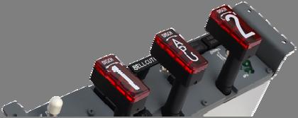
3 Introduction: B737 Fire Engines panel with IDC connection. Mounted in sandwich format professionaly painted and engraved. This panel is designed to connect it directly with an I/O card like the Master or PCB Pedestal. The panel has operative the following components: Select and test switches. Warning and discharge indicators. Fully operative fire handles (without safe triggers). Wiring Fire Engines: FIRE ENGINES B737 IDC connector can be plugged to any I/O card and to Pedestal PCB using 40 contacts IDC connector: The names of the connectors on the PCB panel and the pedestal are the following: PANEL IDC PCB PEDESTAL J1 J17 3
4 Description of connectors Fire Engines: Fire Engines panel is connected to PCB Pedestal 1 (Master nº1, captain's side) when a Fire Cargo panel is present on PCB Pedestal 2 because they are incompatible in the same PCB or Master (they have common outputs). J17 CONNECTOR I/O PIN FUNCTION GND6 1 Comon for Inputs I45...I53 I45 2 OVHT DET B LEFT (1) I46 3 OVHT DET A LEFT (1) I47 4 TEST OVH FIRE I48 5 TEST FAULT INOP I49 6 BELL CUT OUT I50 7 OVHT DET B RIGHT (2) I51 8 OVHT DET A RIGHT (2) I52 9 ENGINE EXTINGUISHER TEST 2 I53 10 ENGINE EXTINGUISHER TEST 1 GND7 11 Common for Inputs I54...I62 I54 12 HANDLE 1 LEFT DISCH I55 13 HANDLE 1 PULL (Switch off when pulled and on when pushed) I56 14 HANDLE 1 RIGHT DISCH I57 15 HANDLE APU LEFT DISCH I58 16 HANDLE APU PULL (Switch off when pulled and on when pushed) I59 17 HANDLE APU RIGHT DISCH I60 18 HANDLE 2 LEFT DISCH I61 19 HANDLE 2 PULL (Switch off when pulled and on when pushed) I62 20 HANDLE 2 RIGHT DISCH GND 21 Comon for outputs O23...O36 O23 22 ENG 1 OVERHEAT O24 23 APU BOTTLE DISCHARGE INDICATOR O25 24 APU DET INOP INDICATOR O26 25 FAULT INDICATOR O27 26 WHEEL WELL INDICATOR O28 27 ENG 2 OVERHEAT O29 28 L BOTTLE DISCHARGE O30 29 R BOTTLE DISCHARGE O31 30 HANDLE 1 ACTIVETED (red led) O32 31 HANDLE APU ACTIVETED (red led) O33 32 HANDLE 2 ACTIVETED (red led) O34 33 L GREEN LED O35 34 APU GREEN LED O36 35 R GREEN LED GND 36 Common for outputs O23...O36 DO21 37 Negative for backlight DO21 38 Negative for backlight PLED 39 Positive for backlight PLED 40 Positive for backlight It takes 2.5 volts to 2.9 volts. ActiveWarning: may burn more voltage backlight! The USBDimcontrol card is recommended. It is also recommended to use 3 volt power for the backlight. 4
5 Declaration of inputs and outputs panel Fire Engines: Manual Fire Engines B737 Panel IDC To declare variables of inputs and outputs must use the following format (the list belongs to the pedestal's definition file of Opencockpits pedestal). // OUTPUTS FIRE ENGINES Var 248, name ENG1_OVHL, Link IOCARD_OUT, DEVICE XX, Output 23 // ENGINE 1 OVERHEAT Var 250, name APUBOTDISL, Link IOCARD_OUT, DEVICE XX, Output 24 // APU BOTTLE DISCHARGE Var 252, name APUDETINOPL, Link IOCARD_OUT, DEVICE XX, Output 25 // APU DET INOPERATIVE Var 254, name FIREFAULTL, Link IOCARD_OUT, DEVICE XX, Output 26 // FIRE ENGINES FAULT Var 256, name FIREWHELLL, Link IOCARD_OUT, DEVICE XX, Output 27 // FIRE WHELL WELL Var 258, name ENG2_OVHL, Link IOCARD_OUT, DEVICE XX, Output 28 // ENGINE 2 OVERHEAT Var 260, name LBOTDISL, Link IOCARD_OUT, DEVICE XX, Output 29 // ENGINE 1 BOTTLE DISCHARGE Var 262, name RBOTDISL, Link IOCARD_OUT, DEVICE XX, Output 30 // ENGINE 2 BOTTLE DISCHARGE Var 264, name FIRE1L, Link IOCARD_OUT, DEVICE XX, Output 31 // ENGINE 1 FIRE HANDLE LIGHT Var 266, name FIREAL, Link IOCARD_OUT, DEVICE XX, Output 32 // APU FIRE HANDLE LIGHT Var 268, name FIRE2L, Link IOCARD_OUT, DEVICE XX, Output 33 // ENGINE 2 FIRE HANDLE LIGHT Var 270, name FIREG1L, Link IOCARD_OUT, DEVICE XX, Output 34 // FIRE ENGINE 1 GREEN LED Var 272, name FIREGAL, Link IOCARD_OUT, DEVICE XX, Output 35 // FIRE APU GREEN LED Var 274, name FIREG2L, Link IOCARD_OUT, DEVICE XX, Output 36 // FIRE ENGINE 2 GREEN LED // INPUTS FIRE ENGINES Var 500, name S_OVHTDET1A, Link IOCARD_SW, DEVICE XX, Input 46 // FIRE ENGINE 1 OVERHEAT A DETECTOR SWITCH Var 502, name S_OVHTDET1B, Link IOCARD_SW, DEVICE XX, Input 45 // FIRE ENGINE 1 OVERHEAT B DETECTOR SWITCH Var 504, name S_FETSTOVH, Link IOCARD_SW, DEVICE XX, Input 47 // FIRE ENGINES TEST OVH-FIRE SWITCH Var 506, name S_FETSTFAULT, Link IOCARD_SW, DEVICE XX, Input 48 // FIRE ENGINES TEST FAULT-INOP SWITCH Var 508, name S_BELLCOUT, Link IOCARD_SW, DEVICE XX, Input 49 // FIRE ENGINES BELL CUT OUT SWITCH Var 510, name S_OVHTDET2A, Link IOCARD_SW, DEVICE XX, Input 51 // FIRE ENGINE 2 OVERHEAT A DETECTOR SWITCH Var 512, name S_OVHTDET2B, Link IOCARD_SW, DEVICE XX, Input 50 // FIRE ENGINE 2 OVERHEAT B DETECTOR SWITCH Var 514, name S_EXT1TEST, Link IOCARD_SW, DEVICE XX, Input 53 // FIRE ENGINE EXTINGUISHER 1 TEST SWITCH Var 516, name S_EXT2TEST, Link IOCARD_SW, DEVICE XX, Input 52 // FIRE ENGINE EXTINGUISHER 2 TEST SWITCH Var 518, name S_HND1DW, Link IOCARD_SW, DEVICE XX, Input 55 // FIRE ENGINE HANDLE 1 DW SWITCH Var 520, name S_HND1L, Link IOCARD_SW, DEVICE XX, Input 54 // FIRE ENGINE HANDLE 1 LEFT SWITCH Var 522, name S_HND1R, Link IOCARD_SW, DEVICE XX, Input 56 // FIRE ENGINE HANDLE 1 RIGHT SWITCH 5
6 Var 524, name S_HNDADW, Link IOCARD_SW, DEVICE XX, Input 58 // FIRE ENGINE HANDLE APU DW SWITCH Var 526, name S_HNDAL, Link IOCARD_SW, DEVICE XX, Input 57 // FIRE ENGINE HANDLE APU LEFT SWITCH Var 528, name S_HNDAR, Link IOCARD_SW, DEVICE XX, Input 59 // FIRE ENGINE HANDLE APU RIGHT SWITCH Var 530, name S_HND2DW, Link IOCARD_SW, DEVICE XX, Input 61 // FIRE ENGINE HANDLE 2 DW SWITCH Var 532, name S_HND2L, Link IOCARD_SW, DEVICE XX, Input 60 // FIRE ENGINE HANDLE 2 LEFT SWITCH Var 534, name S_HND2R, Link IOCARD_SW, DEVICE XX, Input 62 // FIRE ENGINE HANDLE 2 RIGHT SWITCH With this we end this manual, we invite you to read the manuals for the other elements of Opencockpits and SIOC software and we thank you for trusting us. Links of interest: Customer Support Zone: 6
Bombardier Challenger Fire Protection
 GENERAL The fire protection system is divided into two separate subsystems: Fire and overheat detection system; and Fire extinguishing system. The fire and overheat detection system includes components
DASSAULT AVIATION Proprietary Data
 F2000EX EASY 02-26-00 CODDE 1 PAGE 1 / 2 TABLE OF CONTENTS 02-26 02-26-00 TABLE OF CONTENTS 02-26-05 GENERAL Introduction Sources 02-26-10 DESCRIPTION Introduction Fire detection Fire extinguishing Portable
SECTION 6-15 FIRE PROTECTION
 SECTION 6-15 SYSTEMS DESCRIPTION Index Page General Description... 6-15-2 Engine Fire Protection... 6-15-2 Engine Fire Detection... 6-15-2 Engine Extinguishing... 6-15-3 Engine/Wheelwell and Pipe Zone
Fokker 50 - Fire Protection
 ENGINE General The engines are each equipped with a fire detection and a fire extinguishing system. The systems are controlled from the ENGINE FIRE panel, which is located at the overhead panel. Fire and
FR-4000 & FR-8000 Fire Alarm Monitor Installation Manual
 FR-4000 & FR-8000 Fire Alarm Monitor Installation Manual Table of Contents Introduction 1 System Components 2 Wiring Block Diagram 3 Connection Diagram for One Sensor 4 Connection Diagram for Multiple
Added password for IP setup page : Password must be in IP format!
 NETWORK POWER MONITOR Release : 21 August 2014 Hardware Version : Version 7 Firmware version 1.00 PC Application Software : Version (latest)...2 Added password for IP setup page : Password must be in IP
DC3Training.com N28AA DC-3 Pilot s Handbook
 SECTION 7 FIRE PROTECTION Index General page 2 Operation page 4 Limitations page 4 Troubleshooting page 5 4/19/2012 crew@dc3training.com 1 GENERAL The fire protection system consists of an Edison fire
Engine Fire Protection System
 Engine Fire Protection System 1 1 LEFT FEED BUS LEFT CB PANEL CROSSOVER RIGHT FEED LEFT CB PANEL Fire Protection ARM UNLOCK DEPLOY S T EMER O W S NORM W BOTTLE 1 ARMED PUSH LH ENG FIRE PUSH RH ENG FIRE
71717 SERIES FLAMMABLE MATERIAL LOCATIONS
 71 FLAMMABLE MATERIAL LOCATIONS (tab) CAUTION: Rescue crews wearing full PPE to include SCBA s must use caution when moving across sections of aircraft that have been exposed to fatigue or fire as the
How to use the BTRM in Remote Enclosures
 How to use the BTRM in Remote Enclosures Part Number: BTRM-200 Product Release Date: April 01, 2013 Software version: BTRM2_2013-05-06_2316_DNPV2V130D The Ventev Battery Test Remote Monitor (BTRM) has
Section - III SYSTEMS DESCRIPTION
 Section - III SYSTEMS DESCRIPTION Table of Contents Hawker 800XP Pro Line Page GENERAL...4-3 Figure - Engine Fire Detection and Warning System Component Locations...4-3 CONTROLS and INDICATIONS...4-4 ENGINE
Model 4880 Status Output Display Module Manual
 Model 4880 Status Output Display Module Manual 1-2 150912 Section 1 Introduction The 4880 provides 16 switched outputs, 4 form C relay contacts, and an X10 module interface. See Table 2-1 for electrical
WARNING AND TEST MASTER WARNING AND MASTER CAUTION SYSTEMS
 WARNING AND TEST MASTER WARNING AND MASTER CAUTION SYSTEMS The Warning and Caution systems are discussed here in conjunction with the Warning and Test Systems, primarily to cover the procedures for testing
AUTOMATIC FIRE & EXPLOSION SUPPRESSION SYSTEM.
 AUTOMATIC FIRE & EXPLOSION SUPPRESSION SYSTEM www.abdesign.org AFSS SYSTEM INACTIVE ACTIVE 12 ms 24 ms 60 ms 96 ms 120 ms 156 ms 200 ms As a result of their mission, military vehicles are exposed to hydrocarbon
Sigma. K1000 Series 1, 2, 4 & 6 Zone Fire Control Panels. Operation and Maintenance Manual. Man-1048 Issue 05 October 2009
 Sigma K1000 Series 1, 2, 4 & 6 Zone Fire Control Panels Operation and Maintenance Manual Man-1048 Issue 05 October 2009 CONTENTS Contents... Page Safety & Installation...2 Installation - continued...3
P R O D U C T D ATA S H E E T
 TOCSIN 640 Fast, Effective Gas Detection System Controller TOCSIN 640 is a multi-channel detector controller. Easy to install set up and operate with powerful interface features. Two Case Styles Are Available
TABLE OF CONTENTS FIRE PROTECTION. Page. 9-i
 Chapter 9: Fire Protection TABLE OF CONTENTS Page Introduction...9-1 Flight Compartment Fire Warning...9-2 Fire Detecting System...9-2 Main Wheel Well Overheat Warning...9-2 Fire Agent Discharge Indication...9-2
FIRE PROTECTION TABLE OF CONTENTS CHAPTER 9
 TABLE OF CONTENTS CHAPTER 9 Page TABLE OF CONTENTS DESCRIPTION General Flight Compartment Fire Warning Fire Detecting System Wheel Well Overheat Warning Fire Agent Discharge Indication Smoke Detection
DUAL MONITORED INPUT/OUTPUT UNIT BN-305-2
 DUAL MONITORED INPUT/OUTPUT UNIT BN-305-2 Interactive fire detection systems Product Datasheet Features Interactive For interfacing and controlling external units to Autronica s interactive fire detection
Fire Extinguishing System
 Fire Extinguishing System Fire Protection CAUTION CAUTION 1 EXTINGUISHER PUSH L ENGINE FIRE R FW VALVE CLOSED TO TEST R ENGINE FIRE R FW VALVE CLOSED EXTINGUISHER PUSH 2 TEST SWITCH 1 ANNUNCIATOR PANEL
WARNING AND TEST MASTER WARNING AND MASTER CAUTION SYSTEMS
 MODEL 680 WARNING AND TEST MASTER WARNING AND MASTER CAUTION SYSTEMS The Warning and Caution systems are discussed here in conjunction with the Warning and Test Systems, primarily to cover the procedures
APU FIRE EXTINGUISHING SYSTEM - DESCRIPTION AND OPERATION
 1.General APU FIRE EXTINGUISHING SYSTEM - DESCRIPTION AND OPERATION A.The APU fire extinguishing system has controls in two locations that release one application of fire extinguishing agent to a fire
OWNERS MANUAL. To Order Parts Call SPEED AIR MOVER
 3 SPEED AIR MOVER OWNERS MANUAL IMPORTANT: READ OWNERS MANUAL CAREFULLY Please fill out and return your warranty card! MODEL # STR3SPD. REV 01 (6 12) TABLE OF CONTENTS Safety Precautions 3 Machine Operation
ATS1235 Advanced Wireless DGP on 868 MHz AM Installation Sheet
 ATS1235 Advanced Wireless DGP on 868 MHz AM Installation Sheet EN 1 2 1 3 2 4 1 5 12V 6 2 0V D+ D- CON3 7 CON1 ON 3 1 2 3 4 1234 8 3 4 1 0 ON 1 2 3 4 METAL METAL Address 1 1 0 ON 1 2 3 4 Address 2 2011
ACCURATE ELECTRONICS INC
 ACCURATE ELECTRONICS INC Page 1 of 7 Model 108078 2 Sept 09 WWW.ACCURATE.ORG PO BOX 1654 97075-1654 8687 SW Hall Blvd 97008 BEAVERTON OR USA 503.641.0118 FAX 503.646.3903 Practice Section 108078 Rev A
SECTION 2-07 FIRE PROTECTION
 SECTION 2-07 TABLE OF CONTENTS Block General... 2-07-05..01 Engine and APU Fire Protection System... 2-07-10..01 Fire/Overheat Detection... 2-07-10..01 Fire Extinguishing... 2-07-10..04 Controls and Indicators...
FCCP 200: Fume-cupboard indicator and monitor
 Product data sheet 3.1 43.170 FCCP 200: Fume-cupboard indicator and monitor How energy efficiency is improved Display and interface for safe, energy-efficient monitoring of fume cupboards, pressure zones
DOMESTIC HOT WATER Follow operational sequence
 DOMESTIC HOT WATER Follow operational sequence Turn Winter/Summer selector to Summer position. The display is switch on. Go to section A Error 110 flashing Error 131 flashing Turn the selector to reset
Heimdall Radar Traffic Detector
 Heimdall Radar Traffic Detector Traffic Data Detector Installation Guide Document Authorisation Role Name Function Signed Prepared by: R. Martin Project Support Manager Reviewed by: A. Rhodes Lead Product
Heimdall Radar Traffic Detector
 Heimdall Radar Traffic Detector Selectable Speed Detector Installation Guide Document Authorisation Role Name Function Signed Prepared by: R. Martin Project Support Manager Reviewed by: A. Rhodes Lead
SERIES VAC Microprocessor-Based Direct Spark Ignition Control FEATURES APPLICATIONS SPECIFICATIONS DESCRIPTION. Export Information (USA)
") R SERIES 35-70 120 VAC Microprocessor-Based Direct Spark Ignition Control F-35-70 November 2015 FEATURES Safe start with DETECT-A-FLAME flame sensing technology Custom pre-purge and inter-purge timings
R SERIES 35-70 120 VAC Microprocessor-Based Direct Spark Ignition Control F-35-70 November 2015 FEATURES Safe start with DETECT-A-FLAME flame sensing technology Custom pre-purge and inter-purge timings
Products no longer available
 Technical data sheet MONICO-.. Turnkey automation station MONICO-.. Forms an efficient fire protection system together with the motorisation sets BF(G)24MP Completely wired controller in matching control
DUAL MONITORED INPUT/OUTPUT UNIT BN-305
 DUAL MONITORED INPUT/OUTPUT UNIT BN-30 Interactive fire detection systems Product Datasheet Features Interactive For interfacing and controlling external units to Autronica s interactive fire detection
Product No. PLMBZ209GCA Market North America Color stainless steel Volts 120 Watts 1200 Wiring Diagram Owner's Guide TINSEB477MRR0
 Product No. PLMBZ209GCA Market North America Color stainless steel Volts 120 Watts 1200 Wiring Diagram 5995500872 Owner's Guide TINSEB477MRR0 GLMB209D.tif PLMBZ209GCA Cabinet.eps GLMB209DSC Door.eps GLMB209DSC
HRX3000. Technical Manual
 HRX3000 Technical Manual Contents: Specification...2 Connectors...3 Power (J21)...3 RS-485 Network Connectors (J6 and J7)...4 RS-232 to PC (J8)...5 Printer and Fire Alarm Panel (J19)...6 TCP/IP...8 Modem
INSTALLATION INSTRUCTIONS AND OWNER S MANUAL FOR
 INSTALLATION INSTRUCTIONS AND OWNER S MANUAL FOR ELECTRIC ON-DEMAND TANKLESS WATER HEATERS: SpecAdvantage with PhD Technology SafeAdvantage with PhD Technology 208 and 480 VAC three phase 32 144 kw 600
Gas Safety Products. Installation, operating and maintenance. Merlin 1000BH Gas Proving/Gas Detection System
 Gas Safety Products Merlin 1000BH Gas Proving/Gas Detection System Installation, operating and maintenance Read these instructions carefully before operating or servicing Rev: 05 Date: 08-01-18 1 Table
Interfacing with the ADAM Module
 Introduction Interfacing with the ADAM Module Fiber SenSys, Inc. (FSI) has goal to provide our customers with the best security solution available to fulfill their project requirements. Our design and
HRX Technical Manual. Version 1.2
 HRX 5000 Technical Manual Version 1.2 Contents: Specification...2 Connectors...5 RS-485 Network Connectors (J6 and J7)...5 RS-232 to Printer (J19)...6 RS-232 to PC (J8)...7 TCP/IP...8 Power (J21)...9 Fire
Gas Safety Products. Installation, operating and maintenance 23/08/2016. Merlin 1000BH Gas Proving/Gas Detection System
 Gas Safety Products Merlin 1000BH Gas Proving/Gas Detection System Installation, operating and maintenance 23/08/2016 S&S Northern Ltd 1 Table of contents 1 General information... 3 2 Installation... 3
General Purpose IO Technical Manual
 General Purpose IO Technical Manual Revision 1.06 8 November 2013 Pakton Technologies PAE222 GPIO Manual.docx Page 1 of 21 Revision 1.06 Last updated 8/11/2013 Table of Contents INTRODUCTION...3 Scope
Service Quick Guide SQG_CL_15/01_EN
 Service Quick Guide SQG_CL_15/01_EN Indesit Company, Service Department Table - New Platform 2005 Electronic Refrigerators, combination and double-door 1 LED1 LED2 LED3 2 Table 1 In the case of the Led
RED1. Technical Support And Installation Manual. Models ST, E1, E2, E3, E4, and 420. Approved
 RED1 Models ST, E1, E2, E3, E4, and 420 Technical Support And Installation Manual 210111 FM Approved 1. OVERVIEW 1 2. BASIC OPERATION 3 2.1 General 3 2.2 Field-of-View 4 2.3 Range 4 2.4 Environment 4 2.5
AE Liter Tank with Pump Installation Guide
 English AE-301 10 Liter Tank with Pump Installation Guide Corresponding ordering part number: 900043600G Rev. 1.3 UNPACKING: Unpack carefully. Electronic components can be damaged if improperly handled
DC VOLTMETER DCV-10 / 10A / 10C / 10S / 10CS / 11 / 11A / 11C / 11S / 11CS. A4741 / Rev.1
 DC VOLTMETER DCV-10 / 10A / 10C / 10S / 10CS / 11 / 11A / 11C / 11S / 11CS User Manual and Menu Map A4741 / Rev.1 www.entes.com.tr ATTENTION -Disconnect all power before connecting the device. -Don t remove
Vess A2000 Series. IO Terminal Board. User Information. Version PROMISE Technology, Inc. All Rights Reserved.
 Vess A2000 Series IO Terminal Board User Information Version 1.0 2014 PROMISE Technology, Inc. All Rights Reserved. Contents Introduction 1 I/O Terminal Board Features 2 Pin Assignments 3 Sensor Input
Variable Temperature Unit / Booster
 Variable Temperature Unit / Booster Technical manual BVTB500 Version 00 BRUKER The information in this manual may be altered without notice. BRUKER accepts no responsibility for actions taken as a result
Model 3300 Technical Support and Installation Manual
 Model 3300 Technical Support and Installation Manual Manual # T15011 Document Revision: A1 1. OVERVIEW 1 2. BASIC OPERATION 1 2.1 General 1 2.2 Field-of-View 2 2.3 Range 2 2.4 Environment 2 2.5 Configuration
Planning Instructions MEW01090 Revision 4
 Planning Instructions MEW01090 Revision 4 Fire Alarm System EBL128 V1.1.x Author: Jan Pettersson Date of issue: 2008-07-11 Date of rev: 2011-04-08 This page has deliberately been left blank. Table of contents
INSTALLATION INSTRUCTIONS AND OWNER S MANUAL
 INSTALLATION INSTRUCTIONS AND OWNER S MANUAL ELECTRIC INSTANTANEOUS WATER HEATERS WITH PhD 208 and 480 VAC three phase 32 144 kw 600 VAC three phase 130 / 150 kw BEFORE ATTEMPTING ANY INSTALLATION OR SERVICE
DGC-1000 DIGITAL GENSET CONTROLLER
 DGC-1000 DIGITAL GENSET CONTROLLER Basler Electric s Digital Genset Controller (DGC-1000) offers a low cost microprocessor based integrated alternative for small to medium sized genset control and monitoring.
Adaptive CyCLO Technical and HMI User Guide. CyCLO User Guide. Version th December 2017 REV
 CyCLO User Guide Version 2.00 19 th December 2017 REV 2.00 1 Contents 1. Hardware... 3 1.1. Introduction... 3 1.2. Electrical Specification... 3 1.3. Board Overview... 4 1.4. Electrical Installation...
ELECTROPROJECT GTV-A POWER SUPPLY FOR DOOR MAGNETS
 ELECTROPROJECT POWER SUPPLY FOR DOOR MAGNETS Innovative and carefully thought out Always the right drive ELECTROPROJECT AANDRIJFTECHNIEK ElectroProject has evolved over the last 75 years from a technical
FEC403EN Installation Manual
 FEC403EN Installation Manual P/N 10-4101-501-2FC1-01 ISS 22JAN15 Copyright Trademarks and patents Manufacturer 2015 UTC Fire & Security. All rights reserved. The FEC403EN name and logo are trademarks of
Addressable Loop Modules
 Addressable Loop s Introduction FC10MIM The FC10MIM Mini Input module is designed to monitor fire contacts, such as extinguishing system control, ventilation control, fire door control etc. The module
DATASHEET. Burner control unit FDA 601x
 EN 298 / EN 230 2012 19 PCB 100x160mm 3HE/8TE socket DIN 41612 2-channel microprocessor controlled program air valve control for heating / cooling preventilation continuous operation with ionisation intermittent
user manual Document No , Revision 03 November 2015
 user manual Document No. 996-202-600-3, Revision 03 November 2015 Contents 1 Introduction...1 1.1 Notice...1 1.2 Models...1 2 User Control Levels...2 2.1 Level Definition...2 2.2 User Passwords...2 3 Controls
SOLO Single Loop Addressable Fire Control Panel
 Solo Single Loop Analogue Addressable Fire Control Panel Apollo Protocol Installation, Commissioning & Operating Manual Issue 03 June 1999 CONTENTS Section... Page 1. Introduction...1 2. Safety...2 3.
Web Site: Forums: forums.parallax.com Sales: Technical:
 Web Site: www.parallax.com Forums: forums.parallax.com Sales: sales@parallax.com Technical: support@parallax.com Office: (916) 624-8333 Fax: (916) 624-8003 Sales: (888) 512-1024 Tech Support: (888) 997-8267
Planning Instructions MEW01776 Revision -
 Planning Instructions MEW01776 Revision - Fire Alarm System EBL512 G3 V2.2.x Author: Jan Pettersson Date of issue: 2015-01-19 Date of rev: This page has deliberately been left blank. Table of contents
AIS-Module 400. Installation Manual. AIS-Module for: AS 40P, AS 4000, AS 100 IT
 AIS-Module 400 Installation Manual AIS-Module for: AS 40P, AS 4000, AS 100 IT About this manual These instruction apply to the version as shipped. Should the Manufacturer offer new features within the
NexSysLink. 2 CAN Display Operation Manual. CAN Instruments Product Family
 NexSysLink CAN Instruments Product Family 2 CAN Display Operation Manual Contact Beede Beede Electrical Instrument Company, Inc. 88 Village Street Penacook, NH 03303 (603) 753-6362 Toll-free 800-451-8255
ENGINE MONITOR VOTT MODEL: YEAR WARRANTY
 INSTRUCTION MANUAL ENGINE MONITOR VOTT MODEL: 023-4400-0 3 YEAR WARRANTY INTRODUCTION The VOTT meter is an ideal engine monitor, which displays data via the J1939 CAN Bus. The meter utilizes a large LCD
STROBE / SOUNDER INTERFACE
 STROBE / SOUNDER INTERFACE INSTALLATION & CONFIGURATION MANUAL 21/10/2010 Rev: 2.00 DOC-01-002 ECN10-183 Documentation Feedback Your feedback helps us keep our documentation up to date and accurate. If
BSR Addressable Fire Detection control panel. Installation operation manual
 BSR-1116 Addressable Fire Detection control panel Installation operation manual ATTENTION!!! READ THE MANUAL BEFORE THE INSTALLATION AND PAY ATTENTION TO PARAGRAPH 2.6.3 AND 2.6.4. Page 2 from 36 Contents
Control and Indicating Equipment
 VdS Guidelines for Fire Detection and Fire Alarm Systems VdS 2540en Requirements and Test Methods VdS 2450en : 2018-12 (03) Publisher and publishing house: VdS Schadenverhütung GmbH Amsterdamer Str. 172-174
Web Site: Forums: forums.parallax.com Sales: Technical:
 Web Site: www.parallax.com Forums: forums.parallax.com Sales: sales@parallax.com Technical: support@parallax.com Office: (916) 624-8333 Fax: (916) 624-8003 Sales: (888) 512-1024 Tech Support: (888) 997-8267
Smart Homes in. Rajya Sabha Co-operative Housing Society
 Smart Homes in Rajya Sabha Co-operative Housing Society Construction Partners Technical Partners for Smart Society & Homes Introduction Categories Online Enhanced Security Residents Communication Alerts
Marlin Filament Monitoring October 2014
 Why is Filament Monitoring Useful? Marlin Filament Monitoring October 2014 There are a number of filament monitors and filament break detectors available which will generate an alarm if the filament runs
HGM300/RDM800 PREVENTATIVE MAINTENANCE AND TECHNICAL SUPPORT. SECTION 1 HGM300 CPU reset, RDM800 CPU reset, WARM UP notes and HGM300 Self Test
 HGM300/RDM800 PREVENTATIVE MAINTENANCE AND TECHNICAL SUPPORT SECTION 1 HGM300 CPU reset, RDM800 CPU reset, WARM UP notes and HGM300 Self Test SECTION 2 HGM300/RDM800 Mechanical Room layout SECTION 3 HGM300
Fire Control Panel FS4000
 Fire Control Panel FS4000 INSTRUCTION MANUAL Revision 11/01.17 Contents 1. Introduction... 3 2. Terminology... 3 3. Function... 4 4. Technical features... 4 4.1 Fire alarm lines... 4 4.2. Current thresholds
Instruction Manual Model Backup Switch, 1 for 8
 Instruction Manual Model 2582-282 Backup Switch, 1 for 8 December 2011, Rev. 0 MODEL 2582 SWITCH CROSS TECHNOLOGIES INC. SWITCH ALARM PSA PSB ALARM OFFLINE ONLINE UNIT STATUS 1 2 3 4 5 6 7 8 BU PROT MODE
Grandstream Networks, Inc. GDS3710 Input/output Connection Guide
 Grandstream Networks, Inc. Table of Contents INTRODUCTION... 4 GDS3710 WIRING CONNECTION... 5 Powering and Connecting the GDS3710... 5 Power and Data PINs... 5 Alarm In and Alarm Out PINs... 6 DETECT AND
P R O D U C T D ATA S H E E T
 PGF- Effective Gas Safety Proving and Gas Detection Controller Gas Pressure Proving For use with Natural Gas LPG - or Laboratory gas supplies, both high and low pressure ensuring system integrity prior
P R O D U C T D ATA S H E E T
 Keyless RFID Control PGF- Effective Gas Safety Proving and Gas Detection Controller RFID Gas Proving, Ventilation Control & Gas Detection, off one panel Our range of gas proving systems can be used for:
Gas Safety Products. Installation, operating and maintenance 11/26/2015. Merlin Gas Detectors. Merlin Gas Detectors. American Gas Safety LLC 1
 Gas Safety Products Merlin Gas Detectors Installation, operating and maintenance 11/26/2015 American Gas Safety LLC 1 Table of contents 1 General information... 3 2 Installation... 3 2.1 Mounting the Merlin
DET-RWATER Flood Detector Installation Guide
 DET-RWATER Flood Detector Installation Guide Fig 1 1 2 3 4 5 Fig 2 Page 2 2 SUPER DISABLE ALARM ON DRY DISABLE TAMP SENSOR ENABLE VIEW STATE Fig 3 Page 3 1mm Fig 4 Page 4 1. Introduction The DET-RWATER
Setup Instructions. This manual is only valid for A36D/TPSD Chargers. equipped with a 341S control card with P341S0012 or P341S0013 software
 La Marche Manufacturing Company www.lamarchemfg.com DNP 3.0 Serial (RS232/RS485) and Ethernet (TCP/IP) SCADA Interface for A36D & TPSD Chargers with S2A-341S and S2A-383S communication cards. Option 21P,
ACM8 & ACM8CB. Access Power Controllers Installation Guide. - Fused Outputs - Fused Outputs. - PTC Outputs - PTC Outputs. Models Include: Rev.
 ACM8 & ACM8CB Access Power Controllers Installation Guide Models Include: ACM8 ACM8E - Fused Outputs - Fused Outputs ACM8CBE ACM8CB - PTC Outputs - PTC Outputs Rev. 092503 Overview: These units convert
Heimdall Radar Traffic Detector
 Heimdall Radar Traffic Detector Single Lane VA Detector Installation Guide Document Authorisation Role Name Function Signed Prepared by: R. Martin Project Support Manager Reviewed by: A. Rhodes Lead Product
Ethernet General Purpose
 Ethernet General Purpose Technical Manual Revision 1.03 8 November 2013 Pakton Technologies IO PAE224 Ethernet GPIO Manual.docx Page 1 of 22 Revision 1.03 Last updated 8/11/2013 Table of Contents INTRODUCTION...3
Testing strategy and timeline of E-det 80k. Christian Koffmane for the MPG HLL team
 Testing strategy and timeline of E-det 80k Christian Koffmane for the MPG HLL team Sensors - timeline Metallization started 1.05. sensors available August 2016 Wafer level testing 1. Testing after Al1
Engineering Guideline. pac-carriers Type for Yokogawa ProSafe-RS
 Engineering Guideline pac-carriers Type 9195 for Yokogawa ProSafe-RS 2 Engineering Guideline / Yokogawa ProSafe-RS 06.06.2017 Integrated solutions for Yokogawa R. STAHL offers a wide range of customized
Revision November 2013 JVA Technologies. Ethernet General Purpose IO Technical Manual
 Revision 1.03 8 November 2013 JVA Technologies Ethernet General Purpose IO Technical Manual www.jva-fence.com.au Table of Contents INTRODUCTION...3 Scope and Purpose...3 Glossary...3 SPECIFICATIONS...4
Hydrosense. Vimpex Limited. Star Lane. Great Wakering. Essex SS3 0PJ. Tel: +44 (0) Fax +44 (0)
 Fax +44 (0)") Overview of the Water Detection System 2 Components of a System 4 Design & Planning 5 System Installation Notes 7 Control Panel Installation - HSCPI-K3000 8 Control Panel Commissioning HSCPC-K3000 11 Front
Overview of the Water Detection System 2 Components of a System 4 Design & Planning 5 System Installation Notes 7 Control Panel Installation - HSCPI-K3000 8 Control Panel Commissioning HSCPC-K3000 11 Front
ACM8 Series UL Listed Sub-Assembly Access Power Controllers. Installation Guide. ACM8 - Eight (8) Fuse Protected Outputs
 Fuse Protected Outputs") ACM8 Series UL Listed Sub-Assembly Access Power Controllers Installation Guide Models Include: ACM8 - Eight (8) Fuse Protected Outputs ACM8CB - Eight (8) PTC Protected Outputs Rev. 042811 More than just
ACM8 Series UL Listed Sub-Assembly Access Power Controllers Installation Guide Models Include: ACM8 - Eight (8) Fuse Protected Outputs ACM8CB - Eight (8) PTC Protected Outputs Rev. 042811 More than just
OPERATING INSTRUCTIONS FOR LEEC AUTOMATIC CO2 INCUBATORS. MODELS GA2000 and GA2010 MODELS GA3000 and GA3010 With Infrared CO2 detectors CONTENTS
 OPERATING INSTRUCTIONS FOR LEEC AUTOMATIC CO2 INCUBATORS MODELS GA2000 and GA2010 MODELS GA3000 and GA3010 With Infrared CO2 detectors CONTENTS 1.0 GENERAL DESCRIPTION 2.0 INSTALLATION AND SETUP 3.0 DESCRIPTION
QUICKFIT INSTALL HOOK-UP SHEET FOR ESL KIT REV 1.17 OP
 QUICKFIT INSTALL HOOK-UP SHEET FOR ESL KIT REV 1.17 OP PROGRAMMING STARTS Entering Installer mode If you want to get into program mode press followed by your installer code, default set to 000000
Metasys Integrator Cleaver-Brooks Application
 Metasys Connectivity Technical Manual 69. Metasys Integrator Section Application Note Issue Date 0900 APPLICATION NOTE Metasys Integrator Cleaver-Brooks Application lntroduction Page Application Details
30.45 Electric Release PDRP-2001
 The PDRP-2001 Fire Alarm Control Panel (FACP) is a six-zone control panel for single and dual hazard deluge and preaction applications. The FACP is compatible with conventional input devices (2-wire or
P R O D U C T D ATA S H E E T
 P R O D U C T D ATA S H E E T www.internationalgasdetectors.com Transmitters Control Systems OLIVER Sensors IGD Accessories TOCSIN 640 Pre-Configured Gas Detection System, CO2, O2 or N2O With all the features
N M AirControl AHU. Control manual
 N 10.63 M 03-2016 AirControl AHU Control manual EN CONTENTS PAGE 1 - MONITORING AND CONTROL 2 1.1 The program 2 1.2 The HMI terminal 2 1.3 The controller 4 1.4 Description of the air handling units 4
Fire. IMO fire control signs - according to IMO Resolution A.654 (16) (mm) 150x x200
 (mm) 150x x200") IMO fire control signs - according to IMO Resolution A.654 (16) Safety and operating instructions for trained personnel (SIS) - As per ISO 24409, SIS signs are safety-related signs that replicate the symbols
IMO fire control signs - according to IMO Resolution A.654 (16) Safety and operating instructions for trained personnel (SIS) - As per ISO 24409, SIS signs are safety-related signs that replicate the symbols
This wiring harness allows you to connect the Windcrest Unit to a KONE lift with a KRM Communication system.
 Introduction This wiring harness allows you to connect the Windcrest Unit to a KONE lift with a KRM Communication system. The following procedures need to be carried out to minimise the installation time
ACCURATE ELECTRONICS INC PO BOX SW HALL BLVD BEAVERTON OR USA FAX
 Page 1 of 10 Model 10807800 January 2014 ACCURATE ELECTRONICS INC PO BOX 1654 97075-1654 8687 SW HALL BLVD 97008 BEAVERTON OR USA 503.641.0118 FAX 503.646.3903 WWW.ACCURATE.ORG Practice Section 10807800
SMARTELEC 2 ENERGY SAVING CONTROL INSTALLATION AND OPERATING MANUAL
 Instruction Manual. SMARTELEC 2 SmartElec ENERGY SAVING CONTROL INSTALLATION AND OPERATING MANUAL 0 F1 INDEX Section General information ------------------------------------------------------------ 1 Dimensions
FX NET FIRE DETECTION SYSTEM Installation and commissioning manual
 FX NET FIRE DETECTION SYSTEM Installation and commissioning manual Read this manual carefully before installation and commissioning! Installation and commissioning must be performed according to this manual.
ACM4 Series UL Listed Sub-Assembly Access Power Controllers
 ACM4 Series UL Listed Sub-Assembly Access Power Controllers Installation Guide Models Include: ACM4 - Four (4) Fuse Protected Outputs ACM4CB - Four (4) PTC Protected Outputs Rev. 051311 More than just
E21.X.01.6C-05 Operating Manual EB2000 MC page 1. Operating manual EB2000 MC. for up to 9 sensor modules. Version 3.0
 E21.X.01.6C-05 Operating Manual EB2000 MC page 1 Operating manual EB2000 MC EASYBUS-display with MIN-/MAX-alarm for up to 9 sensor modules Version 3.0 Pursuant to EN 50 081-1 and EN 50 082-2 for unlimited
RAEGuard 2 PID. User Guide
 RAEGuard 2 PID User Guide P/N: H-D03-4001-000 Rev M February 2018 Contents Section 1: RAEGuard 2 PID User s Guide 1 General Information... 6 2 General Specifications... 8 2.1 RAEGuard 2 PID Specifications...