Quick Start Guide. XNX Universal Transmitter
|
|
|
- Blaze Camron Rodgers
- 5 years ago
- Views:
Transcription


1 Quick Start Guide XNX Universal Transmitter
2
3 Table of Contents 1 Introduction Warnings Mounting and Location of Detectors Mounting the XNX Universal Transmitter Wiring the XNX transmitter General Wiring Considerations...11 Loading...11 Isolation...12 Circuit Protection...12 Loads Distance Considerations for Installation...12 Types of Installations...12 Power Source Selection...12 Wire Selection...12 Single Transmitter Distances...13 Daisy-Chained Transmitter Distances POD Connections mA Output, Common Connections and Power...16 Setting 4-20mA operation; S1 & S HART Communications...18 Point-to-Point Mode...18 Multi-drop Mode...18 Cable Length Terminal Block Connections EC Personality Wiring XNX Electrochemical (EC) Sensor Installation XNX EC Sensor Remote Mounting Kit mv Personality Wiring mv Remote Sensor Mounting IR Personality Wiring Connecting a Searchpoint Optima Plus or Searchline Excel...30 Attaching the Searchpoint Optima Plus to the XNX Universal Transmitter...30 Searchline Excel and Searchpoint Optima Plus Remote Installation...30 Searchpoint Optima Plus or Searchline Excel Wiring Recommendations Connecting Generic ma Device...32 XNX Universal Transmitter Quick Start Guide 3
4 Table of Contents (cont d) 5 Options Local HART Interface Relays Modbus Foundation Fieldbus Powering the XNX for the First Time XNX Units Configured for EC, mv, and IR (except Searchline Excel) XNX IR Units Configured for Searchline Excel Configuring the XNX Universal Transmitter The XNX Front Panel Controls and Navigation The General Status Screen Entering the Menu Structure Displaying Transmitter Information Gas Calibration Menu Calibration Calibration Procedure Zero and Span Calibration for XNX EC Sensors Zero and Span Calibration of XNX EC Hydrogen Sulfide (H 2 S) Sensors XNX EC Sensor Operational Life Zero and Span Calibration for MPD Sensors MPD Flammable Sensor Cross Calibration procedure for MPD-CB Calibrating the 705/705HT Calibrating the Sensepoint/Sensepoint HT Functional Gas Testing (Bump Test) Sensor Data Operating and Storage Conditions for Performance Tested EC Cartridges EC Sensor Performance Data, Factory Mutual Verified EC Sensor Performance Data, DEKRA EXAM Verified Other EC Sensors XNX Catalytic Bead and IR Replacement Sensor Cartridges Warning Messages Fault Messages Informational Messages Control Drawings Certification Labels Specifications EC Declaration of Conformity XNX Universal Transmitter Quick Start Guide
5 1 Introduction The XNX Quick Start Guide is an abbreviated print reference for the installation, operation, and maintenance of the XNX Universal Transmitter. Refer to the XNX Universal Transmitter Resource CD (Honeywell part number ) for these comprehensive documents, as appropriate, before installing or commissioning the transmitter: Manuals XNX Technical Manual (1998M0738) XNX Quick Start Guide ( ) MPD Operating Manual ( ) XNX Safety Manual ( ) XNX Foundation Field bus Technical Manual (1998-xxxx) Control Drawings 1226E0402 XNX Control Drawing- UL,CSA, XM Approved Model XNX-UT**-****** 1226E0454 XNX Control Drawing- UL, INMETRO Approved Models XNX-BT***** 3000E3159 XNX ECC Cartridge Control Drawing- XNXX***** Series EC Cartridges and Remote Mount Kit. For other sensor types such as Sensepoint Optima Plus, Searchline Excel, model 705 HT, or Sensepoint sensors, refer to their respective manuals for installation and ordering information. XNX Universal Transmitter Quick Start Guide 5
6 2 Warnings High off-scale readings may indicate an explosive concentration of gas. Installation must be in accordance with the recognized standards of the appropriate authority in the country concerned. Any work on the interior of the detector must be conducted only by trained personnel. Ensure that local regulations and site procedures are followed when carrying out any work. Appropriate standards must be followed to maintain the overall certification of the detector. To reduce the risk of ignition of hazardous atmosphere, disconnect the equipment from the supply circuit before opening the detector enclosure. Conduit runs must have a seal fitting connected within 18 inches (45 cm) of the enclosures. Keep the assembly tightly closed during operation. Never open the XNX enclosure under power unless the area is known to be non -hazardous. The detector must be earthed/grounded for Intrinsic Safety, electrical safety, and to limit the effects of radio frequency interference. Earth/ground points are provided inside and outside the unit. EMI note for applications using shielded cable: Cable shield terminations must be made at the cable glands with suitable EMI type glands. Avoid terminating cable shields at the Earth ground lug inside the XNX enclosure. In cases where wiring is in pipe, a shielded cable is not required. The external terminal is only a supplemental bonding connection where local authorities permit or require such a connection. Take care when handling EC sensor cells as they may contain corrosive solutions. Do not tamper with or in any way disassemble the sensor cells. Do not expose the transmitter or sensor cells to temperatures outside the recommended range. Do not expose the sensor to organic solvents or flammable liquids. At the end of their working lives, sensors must be disposed of in an environmentally safe manner. Disposal should be according to local waste management requirements and environmental legislation. Alternatively, sensors may be securely packaged, clearly marked for environmental disposal, and returned to Honeywell Analytics. Do NOT incinerate electrochemical cells as they may emit toxic fumes. Verify all outputs, including display, after installation, after service events, and periodically to ensure the safety and integrity of the system. Delays resulting from transmission errors between sensor and transmitter extend response times T90 by more than one-third. The period until fault indication is 10 seconds. As some test gases are hazardous, exhaust the flow housing outlet to a safe area. Do not use the XNX Universal Transmitter in oxygen-enriched atmospheres. (In oxygen-enriched atmospheres, the electrical safety is not given.) 6 XNX Universal Transmitter Quick Start Guide
7 HAZARDOUS LOCATIONS INSTALLATION REQUIREMENTS (UL/CSA/FM) To reduce the risk of ignition of hazardous atmospheres, conduit runs must have a pour gland installed within 18 inches (457mm) of enclosure. All ¾ inch NPT conduit, stopping plugs and adapters must be installed with 5 ¼ threads (minimum) engaged to Maintain Explosion Proof rating. The XNX Cover Assembly must be fully seated to enclosure 9 threads (minimum) to maintain Explosion Proof rating. Stopping Plugs supplied (Honeywell Part Number ) are approved for use ONLY with the XNX Universal Transmitter. For units fitted with the optional relay module: Relay contact ratings are 250 VAC 5A, 24 VDC 5A Resistive Loads Only. Use copper conductors only, 60/75 C. Terminal block screws should be tightened to 4.5 lb/in maximum. For models XNX-UT**-*****, refer to XNX control drawing 1226E0402 or, for models XNX-BT**-*****, refer to control drawing 1226E0454 for additional information regarding IS function (local HART and EC personalities). XNX Universal Transmitters carrying UL/CSA/FM approvals that are configured for devices measuring %LEL will not allow adjustments to the full scale value. The range is fixed at 100%. HAZARDOUS LOCATIONS INSTALLATION REQUIREMENTS (ATEX) Read and understand Technical Manual 1998M0738 before installation and use. Use only Certified M25 cable glands for installation. Shielded armoured cable is required for CE compliance. Special conditions for safe use The following applies to the HART Barrier intrinsically safe circuits: For installations in which both the Ci and Li of the intrinsically safe apparatus exceeds 1% of the Co and Lo parameters of the associated apparatus (excluding the cable), then 50% of Co and Lo parameters are applicable and shall not be exceeded, i.e. the Ci of the device plus the C of the cable must be less than or equal to 50% of the Co of the associated apparatus, and the Li of the device plus the L of the cable must be less than or equal to 50% of the Lo of the associated apparatus. For circuits connected to the EC barrier in which the capacitance and inductance exceed 1% of the permitted values, then the maximum permitted capacitance is limited to 600nF for group IIC and 1uF for group IIIC. The connection to the HART circuit shall be rated a minimum of IP 6X. XNX Universal Transmitter Quick Start Guide 7
8 3 Mounting and Location of Detectors CAUTION The location of the transmitters and sensors should be made in accordance with any relevant local and national legislation, standards or codes of practice. Always replace detectors with a detector of the same type. The detector should be mounted where the gas is most likely to be present. The following points should be noted when locating gas detectors. Consider the possible damage caused by natural events e.g. rain or flooding when locating detectors. Consider ease of access for functional testing and servicing. Consider how escaping gas may behave due to natural or forced air currents. NOTES: The placement of detectors should be determined following the advice of experts having specialist knowledge of gas dispersion, experts having knowledge of the process plant system and equipment involved, safety and engineering personnel. The agreement reached on the location of detectors should be recorded. CSA certification does not cover XNX EC cartridges or XNX EC cartridge remote mounting kit, daisy-chained XNX combustible gas transmitters or the use of HART, Modbus, or Foundation Fieldbus used for combustible gas performance. HART, Modbus, or Foundation Fieldbus may be used only for data collection or record keeping with regards to combustible gas detection. FM approved configurations (see the XNX Universal Transmitter Technical Manual, section 6.3 XNX Certifications by Part Number Series) also limit the use of HART, Modbus, or Foundation Fieldbus to use for diagnostics, data collection, or record keeping. The XNX Universal Transmitter is certified and designed for installation and use worldwide in hazardous areas. 3.1 Mounting the XNX Universal Transmitter The XNX Universal Transmitter can be mounted in a number of different methods using the integral mounting tabs. Using the mounting tabs, the XNX can be attached to: Flat wall surface Unistrut With the optional Pipe Mount kit, the XNX can be mounted to pipe of diameter 2 to 6 in (50 to 150mm). A ceiling mount bracket kit (1226A0358) is also available. NOTES: Agency certifications require that EC and mv sensors face down. Optima sensors must be mounted horizontally. 8 XNX Universal Transmitter Quick Start Guide


9 Integral Mounting Lugs Figure 1. Integral mounting lugs and optional pipe and ceiling mounts 7.75" mm 6.00" 15.4 mm 5.6" mm 4.48" mm 2.054" 52.18mm 0.625" 15.88mm 0.55" mm 1.67" mm 1.2" 31.75mm 1.768" mm 1.768" mm 0.945" 24mm 3.176" mm 6.138" mm Figure 2. XNX Universal Transmitter mounting dimensions and clearances XNX Universal Transmitter Quick Start Guide 9
10 WARNING When the XNX is equipped with the optional Remote Mount Kit, the remote sensor MUST be securely mounted to a fixed position. The Remote Sensor Kit is not intended to be used as a hand-held detector. The XNX is configured with 5 cable/conduit entries built into the housing for wiring and mounting sensors. Figure 3 provides the guidelines to proper installation of the XNX. A E D* NOTE While relay wiring can use any available cable/conduit entry in the XNX enclosure, do not use the same cable/ conduit entry for both relay reset and relay signal lines to avoid electrical noise. B * Limited access due to IS barrier if equipped with electrochemical cell. C Option Local HART Option MPD, 705 Series, Sensepoint Series Catalytic Bead Sensor Searchpoint Optima Plus Searchline Excel Remote Sensor Connection (except EC ) Searchpoint Optima Plus - Remote Modbus Relays Foundation Fieldbus Power Position B C C A or E Typically C Any remaining Any remaining Any remaining Any remaining Any remaining Any remaining Figure 3. XNX Universal Transmitter cable/conduit entry assignments 10 XNX Universal Transmitter Quick Start Guide

 Sensepoint Local / Remote 705HT Local / Remote MPD Remote Sensepoint PPM Local/Remote Sensepoint HT Remote CAUTION Before wiring the transmitter, confirm that the")


11 4 Wiring the XNX transmitter Personality circuit boards determine the XNX behavior based on the sensor type attached to the XNX interface. The table below defines the three XNX transmitter configurations and the sensors each support. XNX IR Personality XNX EC Personality Searchline Excel SearchpointOptimaPlusLocal/Remote XNX EC Sensor Generic ma Sensors XNX mv Personality XNX EC Sensor Remote Mount Kit 705 Local / Remote MPD Local (cat bead and IR) Sensepoint Local / Remote 705HT Local / Remote MPD Remote Sensepoint PPM Local/Remote Sensepoint HT Remote CAUTION Before wiring the transmitter, confirm that the correct personality boards and options are installed. 4.1 General Wiring Considerations For proper operation of the XNX Universal Transmitter and Sensor Technologies, consideration of wiring induced voltage drops, transient electrical noise and dissimilar Earth ground potentials is imperative in the design and installation of the system. NOTE: EMI note for applications using shielded cable: Cable shield must provide 90% coverage of the wiring. Cable shield terminations must be made at the cable glands with suitable EMI-type glands. Avoid terminating cable shields at the Earth ground lug inside the XNX enclosure. Where wiring is in pipe, a shielded cable is not required. Loading Wiring for DC Power, 4-20mA Signal, remote wiring to sensors must be sized sufficiently to provide sufficient voltages for the line length and the loads that will be used. XNX Universal Transmitter Quick Start Guide 11
12 Isolation Isolating power and signal carrying conductors is recommended. Circuit Protection Supply circuits must provide over current protection. Class 2 power supplies are required for 24 volt DC supply. Consider Inrush current in specifying any DC supply. Power supply range is 16 to 32 VDC for EC and mv versions, 18 to 32 VDC for Searchpoint Optima Plus and Searchline Excel and 16 to 32 VDC dependent on the limitations of device for the generic 4-20mA input. Loads The use of High Inrush or Inductive loads may affect the performance of the XNX. For best reliability use resistive loads only. 4.2 Distance Considerations for Installation Types of Installations There are three basic types of installation: a single transmitter; multiple transmitters connected to a single power source; and multiple transmitters connected in a daisy-chain configuration. Power Source Selection XNX Universal Transmitter Maximum Power Consumption -40 C to +65 C -10 C to +65 C Configuration XNX with toxic sensors XNX with catalytic sensors XNX with infrared cartridge XNX with Searchpoint Optima Plus XNX with Searchline Excel HART over 4-20mA (watts) HART over 4-20mA with Relay, Modbus, or Foundation Fieldbus (watts) HART over 4-20mA (watts) HART over 4-20mA with Relay, Modbus, or Foundation Fieldbus (watts) Wire Selection The type of wire used for connections has an effect on the distance of the installation. This is because some of the voltage is lost in the wire on the way to the transmitter. 12 XNX Universal Transmitter Quick Start Guide

![0 mm 2 ] 1140 feet [347 meters] 660 feet [201 meters] 550 feet [168 meters] 16 AWG [1.5 mm 2 ] 1810 feet [551 meters] 1060 feet [323 meters] 890 feet [270 meters] 14 AWG [2.](/docs-images/82/85703756/images/13-1.jpg "0 mm 2 ] 2890 feet [880 meters] 1690 feet [515 meters] 1410 feet [430 meters] 12 AWG [3.")
13 Single Transmitter Distances For installations that have dedicated wiring between the transmitter and the power supply, use the following chart. These distances assume stranded wire is used. Configuration XNX mv or EC With Sensor XNX IR with SearchpointOptimaPlus XNX IR with Searchline Excel NOTE Single Transmitter Distances 18 AWG [1.0 mm 2 ] 1140 feet [347 meters] 660 feet [201 meters] 550 feet [168 meters] 16 AWG [1.5 mm 2 ] 1810 feet [551 meters] 1060 feet [323 meters] 890 feet [270 meters] 14 AWG [2.0 mm 2 ] 2890 feet [880 meters] 1690 feet [515 meters] 1410 feet [430 meters] 12 AWG [3.5 mm 2 ] 4620 feet [1408 meters] 2690 feet [820 meters] 2260 feet [690 meters] If multiple transmitters are using the same power supply, make sure the power supply wattage rating is high enough to power all transmitters simultaneously. Daisy-Chained Transmitter Distances A few selected scenarios are presented here to provide a base to work from. 1. Several transmitters equally spaced from themselves and the power source. Configuration XNX mv or EC With Sensor XNX IR with SearchpointOptimaPlus XNX IR with Searchline Excel 2 Transmitters - Distance d 18 AWG [1.0 mm 2 ] 380 feet [115 meters] 220 feet [67 meters] 185 feet [56 meters] 16 AWG [1.5 mm 2 ] 600 feet [183 meters] 350 feet [106 meters] 295 feet [90 meters] 14 AWG [2.0 mm 2 ] 960 feet [292 meters] 560 feet [170 meters] 470 feet [143 meters] 12 AWG [3.5 mm 2 ] 1540 feet [469 meters] 900 feet [274 meters] 750 feet [229 meters] XNX Universal Transmitter Quick Start Guide 13
14 Configuration XNX mv or EC With Sensor XNX IR with SearchpointOptimaPlus XNX IR with Searchline Excel 3 Transmitters - Distance d 18 AWG [1.0 mm 2 ] 190 feet [58 meters] 110 feet [33 meters] 90 feet [27 meters] 16 AWG [1.5 mm 2 ] 300 feet [91 meters] 175 feet [53 meters] 145 feet [44 meters] 14 AWG [2.0 mm 2 ] 480 feet [146 meters] 280 feet [85 meters] 235 feet [71 meters] 12 AWG [3.5 mm 2 ] 770 feet [234 meters] 450 feet [137 meters] 375 feet [114 meters] Configuration XNX mv or EC With Sensor XNX IR with SearchpointOptimaPlus XNX IR with Searchline Excel 4 Transmitters - Distance d 18 AWG [1.0 mm 2 ] 110 feet [33 meters] 65 feet [20 meters] 55 feet [17 meters] 16 AWG [1.5 mm 2 ] 180 feet [55 meters] 105 feet [32 meters] 85 feet [26 meters] 14 AWG [2.0 mm 2 ] 290 feet [88 meters] 165 feet [50 meters] 140 feet [43 meters] 12 AWG [3.5 mm 2 ] 460 feet [140 meters] 270 feet [82 meters] 225 feet [68 meters] Configuration XNX mv or EC With Sensor XNX IR with SearchpointOptimaPlus XNX IR with Searchline Excel 5 Transmitters - Distance d 18 AWG [1.0 mm 2 ] 75 feet [23 meters] 45 feet [13 meters] 35 feet [11 meters] 16 AWG [1.5 mm 2 ] 120 feet [36 meters] 70 feet [21 meters] 55 feet [17 meters] 14 AWG [2.0 mm 2 ] 190 feet [58 meters] 110 feet [33 meters] 90 feet [27 meters] 12 AWG [3.5 mm 2 ] 300 feet [91 meters] 180 feet [55 meters] 150 feet [46 meters] 14 XNX Universal Transmitter Quick Start Guide

15 2. Several transmitters installed in pairs with each pair equally spaced from themselves and the power source. These distances assume the paired transmitters are installed within 10 feet [3 meters] of each other. Configuration XNX mv or EC With Sensor XNX IR with Searchpoint Optima Plus XNX IR with Searchline Excel 2 Transmitters - Distance d 18 AWG [1.0 mm 2 ] 485 feet [147 meters] 380 feet [115 meters] 280 feet [85 meters] 16 AWG [1.5 mm 2 ] 775 feet [235 meters] 600 feet [180 meters] 440 feet [134 meters] 14 AWG [2.0 mm 2 ] 1230 feet [292 meters] 960 feet [290 meters] 700 feet [213 meters] 12 AWG [3.5 mm 2 ] 1970 feet [600 meters] 1540 feet [470 meters] 1130 feet [344 meters] Configuration XNX mv or EC With Sensor XNX IR with SearchpointOptimaPlus XNX IR with Searchline Excel 4 Transmitters - Distance d 18 AWG [1.0 mm 2 ] 190 feet [58 meters] 110 feet [33 meters] 90 feet [27 meters] 16 AWG [1.5 mm 2 ] 300 feet [91 meters] 175 feet [53 meters] 145 feet [44 meters] 14 AWG [2.0 mm 2 ] 480 feet [146 meters] 280 feet [85 meters] 235 feet [71 meters] 12 AWG [3.5 mm 2 ] 770 feet [234 meters] 450 feet [137 meters] 375 feet [114 meters] Configuration XNX mv or EC With Sensor XNX IR with SearchpointOptimaPlus XNX IR with Searchline Excel 6 Transmitters - Distance d 18 AWG [1.0 mm 2 ] 95 feet [33 meters] 55 feet [17 meters] 45 feet [14 meters] 16 AWG [1.5 mm 2 ] 150 feet [45 meters] 85 feet [26 meters] 70 feet [21 meters] 14 AWG [2.0 mm 2 ] 240 feet [73 meters] 140 feet [42 meters] 115 feet [35 meters] 12 AWG [3.5 mm 2 ] 385 feet [117 meters] 225 feet [68 meters] 185 feet [56 meters] XNX Universal Transmitter Quick Start Guide 15
16 4.3 POD Connections The illustration in Figure 4 details the connections available on each of the terminal blocks for each type of personality board. E J1 - Remote HART Connector Only A F Option Boards Personality Boards B D C Figure 4. XNX personality board terminal block legend Table A Table B Board Type Function S1 S2 Board Type Connection Function EC Personality Source ECPersonality Power, 4-20mA mvpersonality 4-20mA Output Sink mvpersonality Power, 4-20mA, IR Personality Isolated TB1 Sensor IR Personality Power, 4-20mA, IR Power and Signal Table C Table D Board Type Function S3 S4 Board Type Connection Function IR Personality IR 4-20mA Input Source 6 6 ECPersonality J2 EC IS Barrier Sink 5 5 IR Personality TB2 Com A and B Table E Table F Board Type Connection Function Board Type Connection Function Relay TB4 Remote Reset Connector Relay TB3 Relay Output Modbus SW5 Bus Loop Terminators Modbus TB3 DataConnection Foundation Fieldbus SW5 Simulation Mode Foundation Fieldbus TB3 DataConnection mA Output, Common Connections and Power Setting 4-20mA operation; S1 & S2 The XNX Universal Transmitter allows the user to configure the 4-20mA output to Sink, Source or Isolated mode operation via two programming switches on the POD. The table below shows the S1 and S2 setting and corresponding output configuration. Output Configuration S1 S2 Source Down Up Sink Up Down Isolated Down Down 16 XNX Universal Transmitter Quick Start Guide
17 Power and 4-20mA connections are made at TB-1 and are identical for the EC, IR, and mv personality boards. The minimum loop impedence is 200 ohms; the maximum is 500 ohms when the transmitter is supplied with an input of 16 volts. Failure to perform Calibrate ma Output or with loads outside the recommended values may result in diagnostic warning or fault messages. The total load resistance recommended for the 4-20mA output should be kept lower than 500 ohms, including the resistance of the properly selected 4-20mA cable and input impedance of the equipment to be connected. Controller XNX +VE V R L Signal 2 +ma 1-5 -VE 3 Current Flow 1-3 -V Figure 5. Sink wiring for XNX Controller Terminate cable screen at the detector or controller, not both. XNX +VE V Signal ma R L Current Flow -VE V XNX Source Configuration Figure 6. Source wiring for XNX Controller XNX +V V +V2 +ma 1-5 -V2 -ma 1-6 -V V XNX Isolated Configuration Figure 7. Isolated wiring for XNX XNX Universal Transmitter Quick Start Guide 17
18 The XNX Universal Transmitter power consumption is dependent on the sensor and options for the specific configuration. For proper operation, the input voltage must be maintained at 16 to 32 volts DC (for EC and mv transmitters) or 18 to 32 volts DC (for IR transmitters). The table below defines the XNX typical and maximum power consumption based on configuration: Configuration Max Power Inrush XNX EC 6.2 w <1A, <10ms@24VDC XNX mv 6.5 w <750mA <2ms@24VDC XNX IR (Optima) 9.7 w <1A <10ms@24VDC XNX IR (Excel) 13.2 w <1A <10ms@24VDC HART devices can operate in one of two configurations: point-to-point or multidrop. HART Communications Point-to-Point Mode In point-to-point mode, the 4 20 ma analog output is used to report concentration and the status of the transmitter to a dedicated channel of the control system. Additionally, concentration, status, diagnostics, and configuration are available digitally using the HART protocol. Multi-drop Mode Multi-drop mode allows up to eight transmitters to interface with a single channel of a control system for non-safety-critical applications. NOTE: Use a multi-drop connection for supervisory control installations that are widely spaced such as pipelines, custody transfer stations, and tank farms. The minimum conductor size is 0.51mm diameter (#24 AWG) for cable runs less than 1,524m (5,000 ft) and 0.81mm diameter (#20 AWG) for longer runs. Cable Length Most installations are within the 3,000m (10,000 ft) theoretical limit for HART communication. However, the electrical characteristics of the cable (mostly capacitance) and the combination of connected devices can affect the maximum allowable cable length of a HART network. The following table shows the effect of cable capacitance and the number of network devices on cable length. The table is based on typical installations of HART devices in non-is environments, i.e. no miscellaneous series impedance. 18 XNX Universal Transmitter Quick Start Guide
19 Allowable Lengths Allowable Cable Lengths for Various Capacitances (for 1 mm, #18 AWG shielded twisted pair) 20 pf/ft (65 pf/m) 9,000 ft (2,769 m) 8,000 ft (2,462 m) 7,000 ft (2,154 m) 6,000 ft (1,846 m) Cable Capacitance 30 pf/ft (95 pf/m) 6,500 ft (2,000 m) 5,900 ft (1,815 m) 5,200 ft (1,600 m) 4,600 ft (1,415 m) 50 pf/ft (160 pf/m) 4,200 ft (1,292 m) 3,700 ft (1,138 m) 3,300 ft (1,015 m) 2,900 ft (892 m) 70 pf/ft (225 pf/m) 3,200 ft (985 m) 2,900 ft (892 m) 2,500 ft 769 m) 2,300 ft (708 m) Number of Network Devices NOTE: See Appendix A of the XNX Technical Manual for more information about the Local HART Handheld. 4.5 Terminal Block Connections Customer connections to the XNX are made via pluggable terminal blocks secured to the back of the POD. The terminal blocks are keyed and polarized. A color coded label is affixed to assist in wiring when the block is removed from the POD. The terminals are suitable for use with 12 to 28 AWG or 0.8 to 2.5mm wire. Wire insulation must be stripped 5/16 (0.312) inches or 8mm. Tighten each terminal to a maximum of 4.5 in/lbs. Up to four terminal blocks will be supplied; each will be configured with 2, 6, 9, or 10 positions. Two terminal block jumpers are provided to provide an electrical connection without connecting to the Personality Board. Install the jumpers between pins 1 and 2 and between pins 3 and 4 to support multi-node wiring. For user convenience, a second set of terminals has been provided to eliminate the need for a secondary junction box in multi-node systems. Two terminal block jumpers are provided which enable an electrical connection without connecting to the Personality Board. Install the jumpers between pins 1 and 2 and between pins 3 and 4 to support multi-node wiring. NOTE: Pins 2 and 4 of terminal block TB1 have no internal connection on the personality board. When used in conjunction with the terminal block jumpers, pins 2 and 4 can provide additional 4-20mA connections or power feed for daisy-chained units. XNX Universal Transmitter Quick Start Guide 19
20 Terminal Block Jumper d black OUT TB-1 Terminal Block Figure 8. Pluggable terminal block and terminal block jumper 4.6 EC Personality Wiring WARNING When the XNX is equipped with the optional Remote Mount Kit, the remote sensor MUST be securely mounted to a fixed position. The Remote Sensor Kit is not intended to be used as a hand-held detector. LOCAL 20 ma Operation J1 HART S1 S2 Source Sink S1 S2 Isolated +V VDC 6.2W max. 4-20mA HART EC EC Barrier 1-2 -V ma 1-5 -ma 1-6 TB-1 J2 J1 - Local HART Connector S1 and S2 - Signal Output Jumper Switch Source Sink Isolated S1 S2 J2 - EC Barrier Connector XNX EC TB-1 TB1 Position EC v 4 Figure 9. XNX EC personality board terminal blocks, jumper switches, and terminal block assignments 20 XNX Universal Transmitter Quick Start Guide
21 J1 HART + J2 EC Barrier - S1 S CAUTION Be certain to dress the wires properly to ensure cabling does not contact switches 1-2 on the back of the POD. Do not force the POD into the enclosure as it may indicate an interference condition resulting in damage to the wiring, POD or switch settings. Optional Local HART IS Barrier must be connected to J1 Terminal Block 1 EC IS Barrier must be connected to J2 Local HART IS Barrier (optional) EC IS Barrier HART Adaptor EC Adaptor Sensor Cartridge Sensor Retainer Sensor Cartridge Weatherproof Cap Sensor Retainer Local Sensor Mounted to Transmitter Weatherproof Cap FOR FM COMPLIANCE, THE SUPPLIED TAG WITH XNXXSH1FM, XNXXSC1FM, AND XNXSO1FM CARTRDIGES MUST BE ATTACHED TO THE TRANSMITTER OR REMOTE MOUNT KIT WHERE INSTALLED. Sensor Mounted to Remote Sensor Kit Figure 10. EC personality wiring NOTE: Refer to control drawing 3000E3159 for installation requirements for EC cells and remote mounting. XNX Universal Transmitter Quick Start Guide 21
22 4.6.1 XNX Electrochemical (EC) Sensor Installation CAUTION For biased sensors (e.g. Nitrogen Dioxide) remove the sensor stabilizer from the bottom of the sensor prior to installation. Using Figure 11 as a guide, follow the procedure below: 1. Check that the label on the new sensor is the correct gas type. 2. Unscrew the weatherproof cover, loosen the retainer locking screw with the supplied hex key and unscrew the sensor retainer. 3. Plug in the new sensor taking care to align the sensor pins with the connector. 4. Refit the sensor retainer, tighten the locking screw with the supplied hex key and refit the weatherproof cover. 5. Countdown time of up to 180 seconds (dependent on sensor type) is displayed. 6. Acknowledgement of the gas type will be required before proceeding. For more information on setting gas type, see the XNX Technical Manual Section 2.51 Gas Selection. 7. After the sensor is installed and the gas type is confirmed, the Range, alarm levels and other important settings must be set; see appropriate section in Section 6 - Powering the XNX for the First Time. 8. Once the XNX has been configured, calibrate the detector following the procedures in Section Calibration. Transmitter New Sensor Sensor Retainer & Locking Screw Weatherproof Cap Figure 11. Installing the plug-in sensor 22 XNX Universal Transmitter Quick Start Guide
23 4.6.2 XNX EC Sensor Remote Mounting Kit The remote sensor mounting kit is used to remotely mount the sensor from the transmitter. To remotely mount the sensor, follow the procedure below. 1. Unscrew the weatherproof cover, loosen the retainer locking screw and unscrew the sensor retainer. 2. Remove the sensor by pulling without twisting. 3. Plug the remote sensor cable connector into the bottom of the transmitter and secure the retainer. 4. Route the cable to the location where the remote sensor is to be mounted. 5. Optional: make a loop of cable at the junction box. This will provide some slack for any future re-terminations. 6. Mount the remote sensor junction box. Allow enough room below it to fit the sensor and the weatherproof cover. 7. Plug the sensor into the socket at the bottom of the terminal box. 8. Fit the sensor retainer, tighten the locking screw and fit the weatherproof cover. 9. Calibrate the detector following the procedures in Section Calibration. XNX Universal Transmitter Quick Start Guide 23
24 Connections Pin # Color 1 Yellow 2 Green 3 Blue 4 White 5 Red 6 Black CAUTION Sensor Cartridge Sensor Retainer Weatherproof Cap Take care not to cut the cable too short. Once cut, additional lengths of cable cannot be added as this will invalidate the intrinsically safe certification. HA also recommends that a loop of cable is made at the junction box to allow slack for any future re-termination. The enclosure of the remotely mounted sensor contains aluminum. Care must be taken to avoid ignition hazards due to impact or friction when installed in the Zone 1 location. All cable entry devices and blanking elements shall be certified in type of explosion protection flameproof enclosure Ex e, suitable for the conditions of use and correctly installed. Sensor Mounted to Remote Sensor Kit Figure 12. Installing remote sensor mounting kit 4.7 mv Personality Wiring XNX Universal Transmitter with the mv personality Board allows interface to a number of Honeywell Analytics Multi Purpose Detector (MPD) and field proven 705 and Sensepoint devices. CAUTION Check to ensure the XNX and mv Sensor has the appropriate approvals for your installation prior to commissioning. Check the mv Sensor you are installing has compatible threads - 3/4 NPT or M25. Connections from the mv sensor to the XNX are made via a single pluggable terminal block allowing ease of installation and service. HA recommends an 8 (203mm) service length for wiring be maintained. The wire colors for the connections for each sensor type are shown in the table on the following page. Be sure wires for 4-20mA outputs are routed away from sources of noise such as relay wires. 24 XNX Universal Transmitter Quick Start Guide
25 NOTE The black and red wires f.rom the MPD are not used with the XNX mv Personality Board. Ensure that they are properly isolated from live connections. DO NOT CUT. CAUTION Be certain to dress the wires properly to ensure cabling does not contact switches 1-2 on the back of the POD. Do not force the POD into the enclosure as it may indicate an interference condition resulting in damage to the wiring, POD or switch settings. LOCAL 20 ma Operation S1 S VDC 6.5W max. 4-20mA MPD, 705 HART Sensepoint mv J1 - Local HART Option Connector S1 and S2-20mA Output Jumper Switch S1 S2 J1 Source HART Sink Isolated Source Sink S1 S2 Isolated +V V ma 1-5 -ma 1-6 Sense 1-7 0v 1-8 Ref 1-9 TB internal grounding lugs XNX mv TB-1 Figure 13. XNX mv personality board wiring Wire Color from Sensor mv Catalytic Bead Sensor mv MPD w/ir Sensor TB-1 Desc. Sensept Sensept IR 5% 705 MPD Senspt PPM* 705HT HT CO 2 CH 4 IR Flam Pins 1-6 See subsections in Section 4.4 for pin identification 7 Sense Brown Red Brown 8 0v White Green White 9 Ref Blue Blue Blue *Internal earth ground; approximately one inch of the black sheath that contains the Sensepoint PPM s four wires (red, blue, green, silver) must be split to allow the silver grounding wire to reach the internal grounding lugs. XNX Universal Transmitter Quick Start Guide 25
26 J1 HART S1 S Terminal Block 1 Optional Local HART IS Barrier must be connected to J1 Sense 7 Com Ref 8 9 Internal Ground Lug Sense 7 Com 8 Ref 9 Local HART IS Barrier (optional) HART Adaptor MPD 705 Sensepoint Ground Wire from Sensepoint PPM Figure 14. mv personality wiring (Refer to the table on the preceding page for wire colors.) 26 XNX Universal Transmitter Quick Start Guide
27 4.7.1 mv Remote Sensor Mounting The millivolt (mv) sensor can be mounted remotely from the XNX transmitter. The distance between the transmitter and the remote sensor must comply with the table below which identifies the proper wire gauges and distances to ensure proper operation. AWG Metric Wire Gauge MPD CB1, 705 Series.Sensepoint Series Sensors MPD IC1, IV1 & IF1 Sensors mm 2 12m (47 ft.) 30m (97 ft.) 22 20m (65 ft.) 50m (162 ft.) mm 2 30m (97 ft.) 80m (260 ft.) 18 50m (162 ft.) 120m (390 ft.)* mm 2 80m (260 ft.)* 200m (650 ft.)* * The frequency of zero calibrations may increase due to the changes in wire resistance caused by changing temperatures. To remotely mount the sensor, follow this procedure: 1. Install a junction box in the desired location. Allow sufficient room for installation and calibration of the sensor. (MPD sensors must be installed with the sinter pointing down.) 2. Loosen the retainer locking screw on the transmitter with the supplied hex key. 3. Unscrew the transmitter s weatherproof cover. 4. Run conduit or cable from one of the transmitter s available conduit entries to the location of the remote junction box in accordance with local requirements. UL and CSA require a conduit pour fitting within 45 cm (18 in.) of each enclosure. 5. Mount the remote sensor junction box. Allow enough room below it to fit the sensor and the weatherproof cover. 6. Attach the conduit or cable to the remote junction box. The junction box provides a mounting base for the sensor and contains the associated electronic circuit. UL/CSA Aluminum Junction Box ATEX/IEC Junction Box A-0100 Figure 15. Remote junction boxes XNX Universal Transmitter Quick Start Guide 27
28 7. Plug the connector into the back of the mv personality board. 8. Install the mv sensor. 9. Terminate wiring at the mv sensor. 10. At the transmitter, pass the wires through the ferrite bead as shown in Figure 16 and terminate the wiring at the pluggable terminal block as shown in Figure 14. In remote mount MPD configurations, the three wires from the sensor that connect to the pluggable terminal block must be routed through the supplied ferrite bead (part no , supplied in the accessory kit), as shown in Figure 16. lnternal Ground Lug (do not use) Power Ferrite Bead for Remote Sensor Wiring mv or IR Remote Sensor XNX Universal Transmitter Figure 16. Ferrite bead wiring 11. Verify point-to-point connections before completing the installation and applying power. 12. Calibrate the sensor. 13. Reinstall the weatherproof cover on the transmitter. Note: Environmental conditions that compromise the IP66 protection provided by the weather proof cover will extend published response times. Safety protocols or maintenance procedures that consider these environmental conditions are recommended specific to the installation. 28 XNX Universal Transmitter Quick Start Guide
29 NOTE The black and red wires from the MPD are not used with the XNX mv personality board. Ensure that they are properly isolated from live connections. DO NOT CUT. CAUTION The enclosure of the remotely mounted 705 HT sensor contains aluminum. Care must be taken to avoid ignition hazards due to impact or friction when installed in the Zone 1 location. All cable entry devices and blanking elements of the Junction Box shall be certified in type of explosion protection Ex d or Ex e, suitable for the conditions of use and correctly installed. 14. Attach and wire the sensor into the terminal box. 15. Fit the terminal box lid. 16. Fit the sensor retainer, tighten the locking screw and fit the weatherproof cover (if required). 17. Calibrate the detector following the procedure in Section Calibration. Ensure that wiring is adequately protected from mechanical failure in installation. Specific shorted or open circuit conditions of wiring to the MPD **I** sensors may result in full scale concentration readings prior to, or preventing the internal diagnostic routines from identifying the external installation fault. 4.8 IR Personality Wiring The RS-485 digital communication is the primary interface in which the XNX transmitter reads gas concentration and sensor status from the Optima Plus/ Searchline Excel. If RS-485 communication fails, the Optima Plus/Searchline Excel 4-20mA output becomes the primary source to read gas concentration. Connections from the Searchpoint Optima Plus or Searchline Excel to the XNX are made via two pluggable terminal blocks allowing ease of installation and service (see Figure 20). HA recommends an 8 (203mm) service length for wiring be maintained. Be sure wires for 4-20mA outputs are routed away from sources of noise such as relay wires The Searchpoint Optima Plus or Searchline Excel can be supplied in either Sink or Source mode operation and is typically labeled on the white wire exiting the Searchpoint Optima Plus or Searchline Excel. Use the table in Figure 20 to set S3 and S4 to the complimentary operating state of the equipment. For more information see the Searchpoint Optima Plus Operating Instructions (2104M0508) or the Searchline Excel Technical Manual (2104M0506). CAUTION Be certain to dress the wires properly to ensure cabling does not contact switches 1-4 on the back of the POD. Do not force the POD into the enclosure as it may indicate an interference condition resulting in damage to the wiring, POD or switch settings. XNX Universal Transmitter Quick Start Guide 29
30 WARNING Setting of S3 and S4 while power is applied or improperly set prior to applying power WILL PERMANENTLY DAMAGE the XNX. Both switches must be set in either Source or Sink prior to applying power. Do not adjust switch settings while power is applied to the XNX; permanent damage WILL occur Connecting a Searchpoint Optima Plus or Searchline Excel Connections from the Searchpoint Optima Plus or Searchline Excel to the XNX are made via two pluggable terminal blocks allowing ease of installation and service (see Figure 18). HA recommends an 8 (203mm) service length for wiring be maintained. The Searchpoint Optima Plus or Searchline Excel can be supplied in either Sink or Source mode operation and is typically labeled on the white wire exiting the Searchpoint Optima Plus or Searchline Excel. Use the table in Figure 18 to set S3 and S4 to the SAME output type that appears on the wire tag of the IR device. NOTE: A second, black-handled screwdriver is included for use on terminal blocks 2 and 4. This tool is smaller than the magnetic wand and is designed to fit into the terminal connections on TB2 and TB4. For more information see the Searchpoint Optima Plus Operating Instructions (2104M0508) or the Searchline Excel Technical Manual (2104M0506). Attaching the Searchpoint Optima Plus to the XNX Universal Transmitter For M25 entries, insert the seal (P/N ) into the proper cable/conduit opening then thread the lock nut (P/N ) onto the Optima to the end of the threads. Thread the Optima body into the XNX until the seal compresses and/ or Optima bottoms out. Reverse until the semi-circular pattern of holes on the front of the weather protection are on the bottom (see Figure 17) then tighten the lock nut to the XNX body. Figure 17. Optima body orientation The 3/4 NPT entries do not require the seal and locknut, the form of the threads provide positive locking and sealing. NOTE: When attaching the Searchpoint Optima Plus, be sure to coat the threads with an anti-seize compound to prevent corrosion. 30 XNX Universal Transmitter Quick Start Guide
31 Searchline Excel and Searchpoint Optima Plus Remote Installation Junction Boxes are available for the Searchline Excel and Searchpoint Optima Plus to facilitate remote mounting from the XNX Universal Transmitter. Junction boxes are available for installations requiring UL/CSA or ATEX approvals. Consult the Searchline Excel Technical Handbook (2104M0506) or Searchpoint Optima Plus Operating Instructions (2104M0508) for specifics on remote installations or contact your Honeywell Analytics representative for more information. For remote mount installations, the maximum distance between the XNX Universal Transmitter and the Searchpoint Optima Plus unit is 33m (100 ft.), using 18 gauge wire. Searchpoint Optima Plus or Searchline Excel Wiring Recommendations When wiring the XNX and the Searchpoint Optima Plus or Searchline Excel for remote applications, the General Recommendations of the ANSI/TIA/EIA-485-A standard must be adhered to with the following additions: 1. When mounting the Searchline Excel or Searchpoint Optima Plus, run wiring connections between each Excel or Optima and the XNX in a dedicated separate conduit. 2. Use 18 AWG twisted shielded cable for the RS485 connection between Excel or Optima and the XNX. Make sure that the shield of the cable is grounded to earth and XNX ground on one end ONLY. 3. Avoid running wiring near main cables or other high voltage equipment. 4. DO NOT APPLY 120 Ohm terminating resistors. These resistors are not required due to low data rates. 5. HA recommends that Excel or Optima and the XNX be wired to building ground. The system should be grounded at one point only. INSTALLATION TIP: Always issue a soft reset after connecting the Optima and XNX for the first time. The soft reset is performed by accessing the XNX calibration menu. NOTE: When the soft reset is initiated for the Optima IR Sensor, the RS-485 communication will be interrupted temporarily and faults F120 and/or F161 may be observed. RS-485 communication will be re-established in a few minutes and the faults will be reset automatically in the Non- Latching Mode. The faults must be reset manually in the Latching Mode. XNX Universal Transmitter Quick Start Guide 31
32 J1 LOCAL HART 20 ma Operation S1 S2 Source Sink S1 S2 Isolated +V 1-1 Pair 1: Unit Ground and IR Sense (Cable Shield Grounded ONE END ONLY) 1-2 Pair 2: RS485+ and RS485- (Cable Shield Grounded ONE END ONLY) Pair 3: IR +ve and IR -ve (Cable Shield Grounded ONE END ONLY) Twisted Shielded Pair 18 AWG IR Sens IR -ve IR +ve Junction Box IR Sens (silver) IR +ve (red) IR -ve (black) RS485- RS485+ RS485+ (yellow) RS485- (blue) +ve Power Supply RS485 Cable Shield Ground ONE END ONLY Unit Gnd (green) Single Ground Point Searchline Excel -V ma 1-5 -ma Ir Ir 1-8 Sig 1-9 Ir TB-1 TB-2 Ir Data Searchpoint Optima Plus VDC 13.2W max. 4-20mA HART Searchline Searchpoint S4 S3 Source Sink -ve Figure 18. XNX IR remote wiring 32 XNX Universal Transmitter Quick Start Guide
33 4.8.2 Connecting Generic ma Device IR personality type provides for a Generic ma input under sensor type configuration. The XNX transmitter can be used to convert the ma input to be read over HART protocol or optional Modbus or Foundation Fieldbus and set optional relays (if equipped). Additional configuration of gas type and unit ID for reporting is required (see XNX Technical Manual Section 2.51 Gas Selection). For Generic ma devices, input values below 3mA will generate Fault 155. Use the following schematics to set S3 and S4 to the same output type that appears on the wire tag of the ma device. XNX XNX S3 and S4 should be in the UP position Set ma Device and XNX to the same output type. 24V 7W Max +IR 1-7 +V ma Device R L Signal -IR Current Flow +ma -V XNX XNX S3 and S4 should be in the DOWN position Set ma Device and XNX to the same output type. ma Device +IR 1-7 +V R L Signal -IR Current Flow -ma -V Figure 19. Generic ma device sink/source schematics XNX Universal Transmitter Quick Start Guide 33
34 LOCAL 20 ma Operation S1 S2 4-20mA Searchline VDC HART Searchpoint 13.2W max. J1 HART Source Sink S1 S2 Isolated +V V ma 1-5 -ma Ir Ir 1-8 Sig 1-9 Ir TB-1 TB-2 Ir Data J1 - Local HART Connector S1 and S2-20mA Output Jumper Switch Source Sink Isolated S1 S2 S3 and S4 - IR 20mA Input Jumper Switch S3 S4 Source Sink XNX IR TB S3 S4 Source Sink XNX IR TB-2 TB1 From Searchpoint Optima Desc. Plus Searchline Excel 1 24v 2 3 Gnd See Common Connections Section mA mA v Red 8 0v Black 9 Sig White Terminal No. A B Desc. Earth TB2 From Searchpoint Optima Plus Searchline Excel Blue Orange XNX From Searchpoint Optima Plus Searchline Excel Green/Yellow Figure 20. XNX IR personality board terminal blocks, jumper switches, and wiring guide 34 XNX Universal Transmitter Quick Start Guide
35 J1 HART Gnd Sig S1 S A 1 B 2 Terminal Block 2 IR Data 9 S3 S4 J1 HART Gnd Sig A B S1 S Terminal Block 2 IR Data S3 S4 Optional Local HART IS Barrier must be connected to J1 red Terminal Block 1 black white blue orange Searchpoint Optima Plus Local HART IS Barrier (optional) green, to building ground HART Adaptor green, to building ground Figure 21. IR personality wiring - Searchpoint Optima Plus Optional Local HART IS Barrier must be connected to J1 red Terminal Block 1 black white blue orange ART aptor Local HART IS Barrier (optional) green, to building ground Searchline Excel Figure 22. IR personality wiring - Searchline Excel XNX Universal Transmitter Quick Start Guide 35
36 5 Options 5.1 Local HART Interface Available with any sensor technology or option, this option provides an external access to the HART interface in the XNX. An IS barrier inside the XNX allows the user to attach an external hand-held interrogator for programming and configuration. The external interface is installed in the lower left cable/conduit entry of the XNX and is intrinsically safe (IS). Intrinsically Safe Barrier for HART Interface HART Handheld Interface Connector w/protective Cap Figure 23. XNX Universal Transmitter with HART interface IS barrier installed 5.2 Relays The relay option (XNX-Relay) provides 3 form C (SPDT) normally/ open/ normally closed (NO/NC) contacts for alarm and fault indication. A remote reset is provided to silence alarms. TB4 is provided as a connection to a user installed momentary switch to silence alarms remotely. Exploring the functionality of the relay option board s remote reset switch The remote reset switch (designated TB-4 and labeled Remote Reset SW ) is located on the relay option board. It provides a remote hardware-based reset of faults and alarms to the transmitter. In the event that direct access to the Local User (LUI) and HART interfaces is not possible, alarms and faults from an XNX transmitter may be reset remotely using a switch. The transmitter can be reset by activating a switch (Off-Mom). This will momentarily close the circuit between the two pins of TB4, providing the same functionality as a Reset Alarms & Faults command performed from the main screen of the LUI or the HART interface. NOTE: Relays are not available when the Modbus or Foundation Fieldbus options are installed. Wiring for the relays is through an available cable/conduit entry to a pluggable terminal block. See Figure 24 for the terminal block legend. NOTE: A second, black-handled screwdriver is included for use on terminal blocks 2 and 4. This tool is smaller than the magnetic wand and is designed to fit into the terminal connections on TB4. 36 XNX Universal Transmitter Quick Start Guide
37 TB4 Remote Reset SW Relay Ratings 250VAC 5A 24VDC 5A 3-1 NC TB-3 C NO NC C NO NC C NO Fault Level 2 Level 1 RELAY Warning: Power externally supplied. Disconnect at source prior to servicing. 9 8 TB TB3 Relay Connections Warning: Power externally supplied, disconnect at source prior to servicing Relay Contact Ratings: 250 VAC 5 amps 24 VDC 5 amps TB4 2 1 Relay TB3 1 NC 2 C 3 NO 4 NC 5 C 6 NO 7 NC 8 C 9 NO TB Figure 24. XNX relay option board and terminal block 5.3 Modbus Modbus connections to the XNX are made through a pluggable terminal block on the Modbus interface circuit board. A loop termination point (SW5) is included on the Modbus interface board to provide termination of the Modbus loop. R T =120 TB S5 EOL Term In Out Modbus A A B B S S Use shorting jumper supplied to maintain connection during service Terminals 3-1 through 3-4 are provided to facilitate bus wiring; there is no internal connection to other XNX circuitry. Terminal 3-1 is connected internally to 3-2. Similarly, terminal 3-3 is connected to 3-4 Modbus SW5 - Loop Termination TB3 Modbus Connections Use Jumper to maintain connection during service TB A 6 A 7 B 8 B 9 S 10 S Figure 25. XNX Modbus option board, terminal block, and jumper switch XNX Universal Transmitter Quick Start Guide 37
38 5.4 Foundation Fieldbus Foundation Fieldbus connections to the XNX transmitter are made through a pluggable terminal block on the Foundation Fieldbus option board, shown in Figure 26. A simulation switch (SW5) is included on the board to enable/disable simulation mode. Terminals 3-1 through 3-4 are provided to facilitate bus wiring; there is no internal connection to other XNX circuitry. Terminal 3-1 is connected internally to 3-2. Similarly, terminal 3-3 is conneted internally to 3-4. TB S5 Sim Mode In TB F+ F+ F- Out Modbus FFB 3-4 F- 3-5 FS 3-6 FS Use shorting jumper supplied to maintain connection during service SW5 - Sim switch Jumper assignments Foundation Fieldbus ground cable Internal ground lug to internal ground lug TB3 1 F+ 2 F+ 3 F- 4 F- 5 FS 6 FS Figure 26. Foundation Fieldbus option board, terminal block, and jumper switch 38 XNX Universal Transmitter Quick Start Guide
39 6 Powering the XNX for the First Time 6.1 XNX Units Configured for EC, mv, and IR (except Searchline Excel) After mounting and wiring the XNX, the plug in sensor should be fitted (if equipped) and the installation visually and electrically tested as below. WARNING Prior to carrying out any work, ensure local and site procedures are followed. Ensure that the associated control panel is inhibited so as to prevent false alarms. Minimum and maximum controller alarm levels should not be set at less than 10% or greater than 90% of the full scale range of the detector. CSA and FM agency limits are 60% LEL or 0.6mg/m 3. CAUTION The following procedure should be followed carefully and only performed by suitably trained personnel. 1. Check that the transmitter is wired correctly according to this manual and the associated control equipment manual. 2. If equipped, unscrew the weatherproof cover, loosen the sensor retainer locking screw and unscrew the retainer. 3. Plug in the sensor cartridge taking care to align the sensor pins with the connector holes in the PCB. CAUTION For toxic sensors, remove the shorting clip from the bottom of the sensor prior to installation. For O 2 sensors, there is no shorting clip provided. 4. Refit the sensor retainer, tighten the locking screw and refit the weatherproof cover. NOTE: Before replacing the cover on the transmitter housing, coat the threads with anti-seize compound to prevent corrosion buildup. Also inspect the cover o-ring for cracking or any other defect that might compromise the integrity of the seal. If it is damaged, replace with the o-ring supplied in the accessory kit. 5. Apply power to the XNX which will in turn provide power to the detector. 6. The detector output will be forced to 3mA (default fault/inhibit). 7. The XNX display will enter a start up routine displaying the initialization screen, then the transmitter loads its operating system, data from the sensor and checks if it is the same type transmitter and sensor software version numbers, gas type, the detection range and span calibration gas level, estimated time to next calibration due, and self test result. The boot-up procedure takes approximately 45 seconds. The LCD and LED test is performed in the initialization after powering on. All LCD pixels and LEDs (red, XNX Universal Transmitter Quick Start Guide 39
40 green, and yellow) are turned on for 1.5 seconds. The LCD then goes blank and the LEDs turn off. NOTE: Figure 27. XNX Initialization and General Status screens In the final stages of boot-up, warnings and faults may be observed until the user performs the proper configuration, calibration, and reset activities described in the following sections. See Sections 11 and 12 for descriptions of warnings and faults. 8. Once the General Status screen appears, the transmitter and detector are in normal monitoring mode. NOTE: Calibration of sensors attached to the XNX is mandatory before the detector can be used for gas monitoring. Refer to Section Calibration for the proper procedure. For EC and mv personalities, perform Accept New Sensor Type before calibrating the sensor. 6.2 XNX IR Units Configured for Searchline Excel When powering the XNX fitted to the Searchline Excel, the following procedure must be followed to assure proper installation. CAUTION The following procedure should be followed carefully and only performed by suitably trained personnel 1. Check that the transmitter is wired correctly according to this manual and the associated control equipment manual. 2. Apply power to the XNX which will in turn provide power to the detector. 3. The detector output will be forced to 3mA (default fault/inhibit). 4. The XNX display will enter a start up routine as described in Section Figure 28. XNX Initialization and General Status screens 40 XNX Universal Transmitter Quick Start Guide
41 NOTE: In the final stages of boot-up, warnings and faults may be observed until the user performs the proper configuration, calibration, and reset activities described in the following sections. See Sections 11 and 12 for descriptions of warnings and faults. 5. When the XNX completes boot-up, perform a soft reset on the Excel from the Calibration Menu. 6. Set the Path Length for the application, then align the transmitter and receiver with Align Excel. 7. Once the alignment is complete, a Zero Calibration must be performed on the Excel to complete the commissioning process. (See the Searchline Excel Technical Manual for calibration information P/N 2104M0506). 8. Reset any faults displayed on the XNX display. The XNX and Excel are now ready to monitor. XNX Remote Calibration for MPD Sensors In addition to functional gas testing to ensure the system is operating properly, remote calibration for the MPD CB1catalytic combustible sensor and MPD IV1 and MPD IF1 infrared combustible sensors can be performed provided the following requirements are met: Remote sensor is installed in an indoor environment Internal air velocity does not exceed 0.5 m/s Weather housing part number 0200-A-1640 is installed on the sensor housing A 1 LPM regulator is used for calibration gas delivery The remote calibration procedure should be performed in accordance with Section 6.1 with the exception of the weather guard, part number 0200-A- 1640, which should be used instead of the regular flow housing, part number 1226A0411. Honeywell Analytics recommends MPD sensor calibration at a maximum interval of 180 days (the XNX default value). This value can be reprogrammed in accordance with site procedures to assure the highest level of safety. Correct operation of each sensor should be confirmed before each use by calibration with a certified test gas of known concentration. In addition, the pellistors used in flammable gas sensors can suffer from a loss of sensitivity when in the presence of poisons or inhibitors, e.g., silicones, sulfides, chlorine, lead, or halogenated hydrocarbons. 1 Special states that inhibit the transmitter from detecting gas are indicated as 2 ma on analog outputs. XNX Universal Transmitter Quick Start Guide 41
42 6.3 Configuring the XNX Universal Transmitter The XNX Universal Transmitter can be configured via the front panel by using the menus available in the Configure Menu. For information on accessing and navigating the menus, see Section Controls and Navigation. The XNX is shipped with the following settings: Display Language Date Format Time Format mv Sensor Type (w/mv personality) Alarm Levels Latching/Non-Latching Alarms Display Units English mm/dd/yy HH:MM MPD-IC1 (%Vol) Sensor Cartridge Dependent Alarm: Latching Fault: Non-Latching 4-20 ma Levels 1 Inhibit: 2.0 ma Warning: 3.0 ma Overrange: 21.0 ma Calibration Interval Unit ID Relay Settings Fieldbus Settings PPM, %VOL or %LEL (dependent on personality and sensor choice) 180 Days (HA recommends 30 day interval) XNX #nnnnnnnn Alarm Normally De-Energized HART Address: 0 Mode: Point-To-Point Modbus (if installed) Level 1 Password Access 0000 Level 2 Password Access 0000 Easy Reset Enabled Address: 5 Baud Rate: Yes 42 XNX Universal Transmitter Quick Start Guide


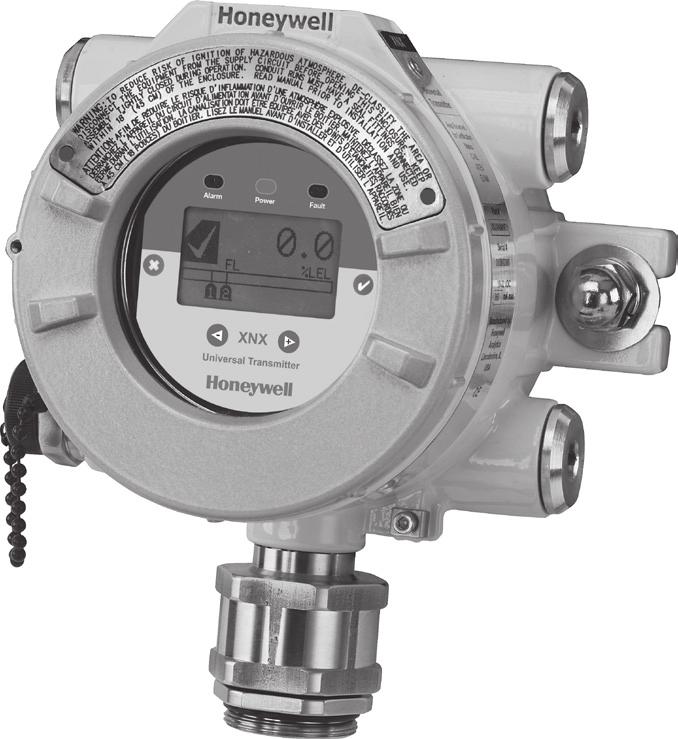
43 7 The XNX Front Panel The XNX uses magnetic switches to enable non intrusive operation. To activate a magnetic switch, hold the factory-supplied magnet up to the glass window and swipe the magnet directly over the shaded area. 7.1 Controls and Navigation Figure 29. The XNX front panel display Control Enter / Accept Escape / Back Move Left / Decrement Value Move Right / Increment Value Action The Enter/Accept key is used to access menus, accept changes and to respond YES to system prompts. The Escape key is used to return to previous menus or to answer NO to system prompts. The Left / Decrement arrow is used to move through menu options or decrement values when entering text or numbers. The Right / Increment arrow is used to move through menu options or Increment values when entering text or numbers. 7.2 The General Status Screen Figure 30. General Status screen The General Status Screen provides a visual indication of the status of the XNX. Warnings, faults, alarm levels and current concentration levels are displayed continuously. XNX Universal Transmitter Quick Start Guide 43


44 Status Indicator Current Concentration Level (Bar Graph) Current Concentration Level (Numeric) Concentration Units Full Scale Alarm 2 Set Point Alarm 1 Set Point Figure 31. General Status screen - normal operating mode The Normal Operating Mode icon gives visual indication of proper operation. When a warning is triggered, the Warning icon appears and information is displayed on the General Status Screen. Warning Icon Warning Code Figure 32. General Status Warning - detail If the fault icon is displayed, a fault condition has been triggered and the display will alternate the display of the target gas concentration and the fault code. Fault Icon Fault Code Figure 33. General Status Fault - detail When an alarm icon is displayed, the target gas concentration exceeds one or both preset alarm levels. The General Status Screen displays the gas concentration and alarm level exceeded. Alarm Icon Alarm Level Triggered Target Gas Concentration Figure 34. General Status Alarm - detail In an overrange condition, the alarm icon will display but the target gas concentration bar graph and alarm setpoints will flash, see illustration below. Alarm Level Triggered Full Scale Concentration Concentration Bar, Alarm Setpoints Flash Figure 35. General Status Overrange - detail In addition to the graphic Alarm, Fault and Warning Figure 38. Zero Calibration Passed 44 XNX Universal Transmitter Quick Start Guide

45 indicators, the LEDs on the front panel will flash in a pattern based on the condition: Condition Alarm 1 Alarm 2 Warning Fault Health 7.3 Entering the Menu Structure LED Red Green Yellow Solid Flashing Solid Flashing Flashing Swiping the magnet over the magnetic switch or gives the user access to the XNX to reset faults and/or alarms, display current settings or make adjustments to the device. NOTE: If the Reset option is set to Lock, users will not have access to reset alarms and faults. For more information on Security Settings for the XNX, see XNX Universal Transmitter Technical Manual. Figure 36. Alarm Reset screen From the General Status menu, if the or escape magnetic switch is swiped, the Alarm Reset Screen activates. This allows any user to silence alarms and reset faults generated by the XNX. Using the switch resets all alarms and faults and returns to the General Status Screen. Choosing X will return to the General Status Screen without resetting the alarms and faults. Figure 37. Passcode screen Using the switch will return the user to the General Status Menu. If the user selects from the General Status menu, it will activate the passcode screen. There are two levels that control access based upon the security level of the user. The passcodes for both levels are set at 0000 from the factory. Level 1 Routine Maintenance Level 2 Technician and Password Admin WARNING The factory-set passcodes must be reset to prevent unauthorized access to the XNX menus (see the XNX Universal Transmitter Technical Manual). Once the Passcode Screen is displayed, the first passcode digit is highlighted. Use the switches to increment or decrement through the values. Once the correct value is displayed for the first digit, accepts the value and moves to the next digit or will move to the previous digit of the passcode. XNX Universal Transmitter Quick Start Guide 45


46 Figure 39. Entering the passcode Repeat for each of the remaining digits in the passcode. If the passcode is not entered correctly, the Invalid Passcode screen is displayed and the user is returned to the General Status screen. 7.4 Displaying Transmitter Information While in the General Status display, swiping the magnet over the magnetic switch will display information about the transmitter. The General Status display will replace the bargraph in the lower portion of the screen with the unit serial number, date and time, as well as the unit part number. Figure 40. General Status screen with unit information 8 Gas Calibration Menu The Gas Calibration menu is used for Zero and Span calibration as well as functional gas testing (bump test). The Gas Calibration menu is accessed from the main menu screen. Figure 41. Gas Calibration menu Function Symbol Gas Calibration Bump Test Align Excel Calibrate ma Output Soft Reset 46 XNX Universal Transmitter Quick Start Guide

47 8.1 Calibration WARNING Do not use the XNX Universal Transmitter in oxygen-enriched atmospheres. Concentrations displayed will be adversely affected by oxygen depletion. CAUTION The calibration procedure should only be performed by qualified personnel. NOTE: The default calibration values for the Calibration Required diagnostic vary based on sensor type. This value can be reprogrammed in accordance with site requirements to ensure the highest level of safety. Correct operation of each sensor/detector should be confirmed using calibration with a certified test gas of known concentration before commissioning. See Section 9 - Sensor Data for calibration gas specifications Calibration Procedure NOTE: Follow the specific procedure outlined in the Operating Manual for each sensing device. The Zero Calibration procedure should be performed prior to the Span Calibration procedure. 1. If using compressed gas cylinder, attach the calibration gas flow housing onto the bottom of the sensor and apply the gas. 2. Access the calibration mode. The Gas Calibration menu is for both Zero and Span Calibration. Zero Calibration Figure 42. Gas Calibration menu Sensor Reading at Current Settings Figure 43. Zero Calibration screen Figure 44. Zero Calibration in Progress Select then apply the zero gas. As the sensor detects the gas and the concentration increases, the values displayed will reflect the changing concentration. Selecting will return to the Gas Calibration menu. XNX Universal Transmitter Quick Start Guide 47


48 3. If the Zero Calibration is successful, the XNX Universal Transmitter will display the Zero Passed screen. Span Calibration NOTE: If a Span Calibration is not required, select the to skip the Span Calibration and return to the Calibration menu. 4. When the Zero Calibration is complete or it is skipped, the Span Concentration screen appears to indicate the concentration value of the gas used for calibration. Figure 45. Span Gas Concentration screen 5. Select to choose the first digit and use the switches to increment or decrement the values. Select to accept the new value and move to the next digit. Continue until all 3 digits have been selected. Sensor Reading at Current Settings Calibration Gas Concentration Figure 46. Span Calibration screen 6. Select then apply the target gas. As the sensor detects the gas and the concentration increases, the sensor reading values in the display will change to reflect the changing concentration. 7. When the concentration values stabilize, the gas concentration as read by the installed sensor is stable. At this time, the gas readings are taken by the sensor. The Span Calibration process also determines whether the sensor is within the proper range to accurately detect the target gas. 8. When the sensor has completed the calibration and the span algorithms have determined that it is within range, the Span Passed screen will appear. If the calibration is not successful, the Span Failed screen will display. Selecting will return to the Span Concentration screen to begin the span calibration again. will exit Span Calibration and return to the Main Calibrate screen. Arrow indicates gas values too low Selecting returns to the Span Concentration screen Figure 47. Span Calibration Failed screen Once the Zero and Span calibrations are completed successfully, the XNX will exit the calibration procedure. Before returning to the Gas Calibration menu however, the user will be prompted to exit with inhibit off, exit with inhibit on, or not exit. 48 XNX Universal Transmitter Quick Start Guide

49 Figure 48. Exiting options WARNING While XNX is in Inhibit Mode, alarms are silenced. This will prevent an actual gas event from being reported. Inhibit Mode must be reset after testing or maintenance activities Zero and Span Calibration for XNX EC Sensors CAUTION Before initial calibration, allow the detector to stabilize for 30 minutes after applying power. When in zero and span calibration mode, the current output from the detector is inhibited (default 3mA) to avoid false alarms. It is recommended for most sticky gases (i.e.: HCl, Cl 2 ) the tubing should be PTFE with short pieces of rubber tube to make the final connection due to the inflexibility of PTFE. This minimizes adhesion of the gas to the tube surface and allows for more accurate measurement. Recalibration is recommended if the temperature of local environment has varied by more than +/-15 degrees C from the temperature of calibration. EN performance standards require 10 minutes stabilization time for application of zero and span gas for performance-approved EC, mv, and IR sensors prior to calibration.. To calibrate the detector, use an appropriate span gas cylinder, flow regulator set to mL/min, tubing, magnet and calibration gas flow housing. A compressed gas cylinder (20.9%Vol oxygen) should be used to perform the zero calibration if the area where the detector is located contains any residual amount of the target gas. If no residual gas is present then the background air can be used to perform the zero calibration. Contact your HA representative for details of suitable calibration kits. To calibrate the detector follow the procedure in Section NOTE: The Oxygen sensor does not require a zeroing procedure. Background air (20.9%Vol oxygen) can be used to span the oxygen sensor in place of a compressed air cylinder (20.9%Vol oxygen). See section of the XNX Technical Manual for other EC sensors Zero and Span Calibration of XNX EC Hydrogen Sulfide (H 2 S) Sensors CAUTION Before initial calibration, allow the detector to stabilize for 30 minutes after applying power. When in zero and span calibration mode, the current output from the detector is inhibited (default 3mA) to avoid false alarms. Recalibration is recommended if the temperature of local environment has varied by more than +/-15 degrees C from the temperature of calibration. Hydrogen Sulfide sensors can be affected by extreme humidity changes. A XNX Universal Transmitter Quick Start Guide 49
50 sudden increase in ambient humidity can result in a short-term positive drift in the instrument s reading. A sudden decrease in ambient humidity can result in a shortterm negative drift in the instrument s reading. These are most likely to be noticed during calibration with dry or cylinder gas. When calibrating Hydrogen Sulfide cartridges the following should be taken into account while following the procedure in Section 8.1.1: 1. To zero the sensor, use a compressed gas cylinder of 20.9%Vol oxygen (not Nitrogen). Do not use background air. 2. If a span calibration is to be performed, the span calibration gas should be applied to the sensor immediately after the zeroing procedure. Do not allow the sensor to return to ambient air conditions XNX EC Sensor Operational Life Typical life of a toxic gas sensor is dependent on the application, frequency and amount of gas exposure. Under normal conditions, with a 3 month visual inspection and 6 month test/re-calibration, the toxic sensor has an expected life equal to or greater than the lifetime as listed below: 12 months for Ammonia and Hydrogen Fluoride sensors. (See Ammonia note below.) 24 months for Chlorine Dioxide, Oxygen, and other toxic sensors. CAUTION Oxygen deficient atmospheres (less than 6%V/V) may result in inaccuracy of reading and performance. NOTE: Ammonia electrochemical cells are reliable and suitable for applications where no background concentration of ammonia exists. Under these conditions the cells are expected to operate for 12 to 24 months. These ammonia cells are of the consumptive type. Their operating life can be adversely affected by continuous or excessive exposure to ammonia, or by prolonged exposure to high temperatures and moisture. To ensure continued detection availability, it is recommended that the detectors are regularly bump tested and a relevant cell replacement program be implemented Zero and Span Calibration for MPD Sensors CAUTION Extended or frequent exposure to elevated concentrations of combustible gases may affect sensor sensitivity. Verify sensor performance by frequent calibration. CAUTION Before initial calibration, allow the detector to stabilize for 30 minutes after applying power. When in zero and span calibration mode, the current output from the detector is inhibited (default 3mA) to avoid false alarms. 50 XNX Universal Transmitter Quick Start Guide
51 This section describes how to calibrate MPD flammable sensors fitted to the XNX. The calibration adjustments are made on the XNX s display and gassing is performed at the sensor. This may be locally or remotely located. The following equipment is required: Flow Housing (Part No: 1226A0411) Test gas Regulator NOTE: Zero gas and Span gas should be at roughly the same humidity levels to avoid erroneous cell responses. 1. At the MPD, remove the Weatherproof Cap if equipped. 2. Fit the Flow Adaptor onto the MPD. Figure 49. Flow adaptor Reverse the cap removal procedure. The following diagram shows the Flow Adaptor accessory fitted to the MPD. NOTE Figure 50. MPD with flow adaptor The Gas Calibration menu is for both Zero and Span Calibration. 3. Connect the Flow Adaptor (using either gas pipe) to the regulated cylinder containing a known concentration of the target gas at approximately the sensor alarm point (e.g. 50% LEL Methane in air). WARNING As some test gases may be hazardous, the Flow Housing outlet should exhaust to a safe area. 4. Follow the procedure in Section 8.1 for both Zero and Span calibrations. XNX Universal Transmitter Quick Start Guide 51
52 5. Apply the target gas to the sensor. Pass the gas through the Flow Adaptor at a rate of 0.5 l/m ±0.2 l/m. NOTE: Sensors should be calibrated at concentrations representative of those to be measured. It is always recommended that the sensor is calibrated with the target gas it is to detect. CAUTION Where the user calibrates any sensor using a different gas, responsibility for identifying and recording calibration rests with the user. Refer to the local regulations where appropriate. 6. Ensure that the sensor and the vicinity around it is clear all traces of the calibration gas before continuing. This is to avoid triggering spurious alarms. If calibration fails at any point, discard the cartridge and replace with a new one. 7. Remove the test equipment, refit the weatherproof cap to the sensor (if previously removed for the test) and return the system to normal operation MPD Flammable Sensor The pellistors used in the flammable gas sensor can suffer from a loss of sensitivity when in the presence of poisons or inhibitors, e.g., siliconse, sulfides, chlorine, lead, or halogenated hydrocarbons. The pellistors are poison resistant to maximixe the operational llife of the flammable sensor Cross Calibration procedure for MPD-CB1 CAUTION Where the user calibrates any sensor using a different gas, responsibility for identifying and recording calibration rests with the user. Refer to the local regulations where appropriate. When the MPD-CB1 Combustible LEL sensor is to be calibrated with a gas which is different from the gas or vapor to be detected, the following cross calibration procedure should be followed: NOTE The first table on page 49 lists the gases according to the reaction they produce at a given detector. An eight star (8*) gas produces the highest output, while a one star (1*) gas produces the lowest output. (These are not applicable at ppm levels.) 52 XNX Universal Transmitter Quick Start Guide
53 Gas Star Rating Gas Star Rating Gas Star Rating Acetone 4* Ethane 6* Nonane 2* Ammonia 7* Ethanol 5* Octane 3* Benzene 3* Ethyl acetate 3* Pentane 4* Butanone 3* Ethylene 5* Propane 5* Butane 4* Heptane 3* Propan-2-ol 4* Butyl acetate 1* Hexane 3* Styrene 2* Butyl acrylate 1* Hydrogen 6* Tetra hydrafuran 4* Cyclohexane 3* Methane 6* Toluene 3* Cyclohexanone 1* Methanol 5* Triethylamine 3* Diethyl ether 4* MIBK 3* Xylene 2* To cross calibrate the MPD-CB1 combustible gas sensor: 1. Obtain the star rating for both the test gas and the gas to be detected from the table above. 2. Set the gas selection to the star rating which is the same star rating of the gas being detected. 3. These values may then be used in the following table to obtain the required meter setting when a 50% LEL test gas is applied to the detector. * Rating of Calibration Gas * Rating of Gas to be Detected 8* 7* 6* 5* 4* 3* 2* 1* 8* * * * * * * * NOTE These settings must only be used with a calibration gas concentration of 50% LEL. 4. If a sensor is to be used to detect a gas other than that for which it was calibrated, the required correction factor may be obtained from the following multiplication table. The meter reading should be multiplied by this number in order to obtain the true gas concentration. XNX Universal Transmitter Quick Start Guide 53
54 NOTE EXAMPLE Sensor calibrated to detect Sensor used to detect 8* 7* 6* 5* 4* 3* 2* 1* 8* * * * * * * * Since combustible sensors require oxygen for correct operation, a mixture of gas in air should be used for calibration purposes. Assuming average performance of the sensor, the sensitivity information in Tables 1 to 3 is normally accurate to +20%. If target gas to be detected is Butane and the calibration gas available is Methane (50% LEL): 1. Look up the star rating for each gas in the first table on page 51: Butane 4* and Methane 6*. 2. Check the meter settings for 50% LEL calibration gas in the second table: The meter should therefore be set to 78% to give an accurate reading for Butane using 50% LEL Methane as a calibration gas. NOTE It is important to calibrate the sensor at the approximate alarm levels to allow for non-linearity of the sensors at gas concentrations above 80% LEL. 54 XNX Universal Transmitter Quick Start Guide
55 8.1.8 Calibrating the 705/705HT For more complete calibration and configuration information, see the Type 705 Operating Instructions (p/n:00705m5002) Calibrating the Sensepoint/Sensepoint HT For more complete calibration and configuration information, see the Sieger Sensepoint Technical Handbook (p/n:2106m0502) Calibrating the Searchline Excel and Searchpoint Optima Plus Complete calibration and configuration information can be found in the Searchline Excel Technical Handbook (p/n:2104m0506) and the Searchpoint Optima Plus Operating Instructions (p/n:2108m0501). If properly installed and maintained, the Searchpoint Optima Plus sensor will not require routine calibration. This is due to the inherent stability of the IR absorption process and the unit s fully compensated optical configuration. XNX Universal Transmitter Quick Start Guide 55

56 8.2 Functional Gas Testing (Bump Test) WARNING Honeywell recommends periodic bump tests (every 30 days or in accordance with customer site procedures) to the sensor to insure proper operation and compliance with the Functional Safety rating of the installation. WARNING Exposure to desensitizing or contaminating substances or concentrations causing operation of any alarm may affect sensor sensitivity. Following such events, it is recommended to verify sensor performance by performing a functional gas test (bump test). CAUTION The calibration procedure should be performed only by qualified personnel. Take appropriate precautions with cylinders of flammable and toxic gases.. It is recommended that the detector is tested frequently to ensure the system is operating properly. Keep in mind different sensor types may require more frequent maintenance depending on the environmental conditions and gases present. The weatherproof cover has a spigot for attaching tubing from a gas cylinder. This may be used for a simple functional (or bump) test of the sensor. However, this method may not be suitable for all gas types and/or applications due to environmental conditions. It is the responsibility of the user to ensure suitability of this method for each application. 1. When bump gas is applied to the sensor, the bump test screen displays the current reading of the sensor and the peak reading that has occurred during the bump test. Peak Reading Current Sensor Reading Full Scale Alarm Levels Figure 51. Bump Test screen 2. If the difference between reading and applied gas concentration is outside the acceptable limits for the application follow the procedures for zeroing and calibrating the detector (see Section 8.1). 3. If reading is still inaccurate replace the sensor. 56 XNX Universal Transmitter Quick Start Guide
Technical Manual Table of Contents Safety Information Introduction Installation and Operation
 XNX Universal Transmitter Technical Manual Table of Contents Safety Information Introduction Installation and Operation Calibration Maintenance Warnings/Faults Specifications Control Drawings HART Protocol
Technical Manual. Sensepoint XCD Gas Detector PRE-LAUNCH
 Technical Manual Sensepoint XCD Gas Detector PRE-LAUNCH 1 Safety Ensure that this Operating Manual is read and understood BEFORE installing / operating / maintaining the equipment. Pay particular attention
Training Presentation XNX
 Training Presentation XNX Premium Gas Detection Wide range of markets and applications including: - Refineries and chemical plants, onshore oil and gas terminals, production platforms, exploration and
XNX Universal Transmitter. A universal transmitter compatible with all Honeywell Analytics gas sensor technologies DRAFT
 XNX Universal Transmitter A universal transmitter compatible with all Honeywell Analytics gas sensor technologies XNX Universal Transmitter Flexible Compatible with all Honeywell Analytics gas sensors
XNX Universal Transmitter
 XNX Universal Transmitter A universal transmitter compatible with all Honeywell Analytics gas sensor technologies XNX Universal Transmitter Flexible Compatible with all Honeywell Analytics gas sensors
Sieger Sensepoint. Easy to Use Factory set operation Simple to replace Minimal training required
 Sieger Sensepoint The Sensepoint range of flammable, toxic and oxygen gas detectors offer users a high quality, low cost solution to their industrial gas monitoring needs. Sieger Sensepoint Fit For Purpose
Technical Manual. Sensepoint XCD Gas Detector
 Technical Manual Sensepoint XCD Gas Detector 1 Safety Ensure that this Technical Manual is read and understood BEFORE installing / operating / maintaining the equipment. Pay particular attention to Warnings
XNX Universal Transmitter
 XNX Universal Transmitter A universal transmitter for toxic, oxygen and combustible gas detection compatible with all Honeywell gas sensing technologies XNX Universal Transmitter Universal Gas Sensing
Sieger Sensepoint. Easy to Use Factory set operation Simple to replace Minimal training required
 Sieger Sensepoint The Sensepoint range of flammable, toxic and oxygen gas detectors offer users a high quality, low cost solution to their industrial gas monitoring needs. Sieger Sensepoint Fit For Purpose
Technical Manual. Series 3000 MkII Gas Detector
 Technical Manual Series 3000 MkII Gas Detector 1. Safety Ensure that this Operating Manual is read and understood BEFORE installing / operating / maintaining the equipment. Pay particular attention to
Nitrogen Dioxide (NO2) Single-Point Gas Detection System
 Single-Point Gas Detection System") Nitrogen Dioxide (NO) Single-Point Gas Detection System DESCRIPTION Wall-mounted gas monitor with built-in nitrogen dioxide (NO)/diesel fume gas sensor, accepts one analog remote device such as a secondary
Nitrogen Dioxide (NO) Single-Point Gas Detection System DESCRIPTION Wall-mounted gas monitor with built-in nitrogen dioxide (NO)/diesel fume gas sensor, accepts one analog remote device such as a secondary
Model D12-IR. Digital Gas Transmitter...
 Model D12-IR Digital Gas Transmitter... ATI s Series D12 gas transmitter line now includes a versatile Infrared system that can be configured for LEL or select toxic gases. The D12-IR utilizes a compact
Technical Handbook. Sieger DX100 Series Termination Units
 Technical Handbook Sieger DX100 Series Termination Units SAFETY Ensure that you read and understand this handbook BEFORE installing/operating the equipment. Pay particular attention to the Safety Warnings.
Sensepoint. Fit For Purpose Flammable, toxic and oxygen versions available High performance, low cost Suitable for new and retro fit applications
 Sensepoint The Sensepoint range of flammable, toxic and oxygen gas detectors offer users a high quality, low cost solution to their industrial gas monitoring needs. Sensepoint Fit For Purpose Flammable,
MAN0604_Issue 09_ Apex
 Technical Handbook 1 SAFETY Ensure that you read and understand this handbook BEFORE installing/operating the equipment. Pay particular attention to the Safety Warnings. Warnings 1. This gas detection
Sensepoint. Fit For Purpose Flammable, toxic and Oxygen versions available High performance, low cost Suitable for new and retro fit applications
 Sensepoint The Sensepoint range of flammable, toxic and Oxygen gas detectors offer users a high quality, low cost solution to their industrial gas monitoring needs. Sensepoint Fit For Purpose Flammable,
Sensepoint XCD RTD (Remote Toxic Detector) Technical Manual
 Technical Manual") Technical Manual Sensepoint XCD RTD (Remote Toxic Detector) Technical Manual 1 Safety Ensure that this Technical Manual is read and understood BEFORE installing / operating / maintaining the equipment.
Technical Manual Sensepoint XCD RTD (Remote Toxic Detector) Technical Manual 1 Safety Ensure that this Technical Manual is read and understood BEFORE installing / operating / maintaining the equipment.
Sieger Apex. Flexibility that meets your requirements
 Sieger Apex Flexibility that meets your requirements Sieger Apex Easy to Install Sensor can be remotely mounted up to 100m from the transmitter On board relays allow for local audible/ visual alarms Strong
Dräger Polytron 8200 CAT Detection of flammable gases and vapors
 Dräger Polytron 8200 CAT Detection of flammable gases and vapors The Dräger Polytron 8200 CAT is an advanced explosion proof transmitter for the detection of flammable gases in the lower explosion limit
P R O D U C T S P E C I F I C A T I O N MSA Ultima X Series Sensor/Transmitter Specification
 P R O D U C T S P E C I F I C A T I O N MSA Ultima X Series Sensor/Transmitter Specification 1.0 This specification details the attributes and operating characteristics of the MSA Ultima X Series sensors/transmitters.
Dräger Polytron 8310 IR Detection of flammable gases and vapour
 Dräger Polytron 8310 IR Detection of flammable gases and vapour The Dräger Polytron 8310 IR is an advanced explosion proof transmitter for the detection of combustible gases in the lower explosion limit
Carbon Monoxide Transmitter
 Introduction The CO Transmitter uses an electrochemical sensor to monitor the carbon monoxide level and outputs a field-selectable 4-20 ma or voltage signal. The voltage signal may also be set to 0-5 or
Dräger Polytron 8700 IR Detection of flammable gases and vapors
 Dräger Polytron 8700 IR Detection of flammable gases and vapors The Dräger Polytron 8700 IR is an advanced explosion proof transmitter for the detection of combustible gases in the lower explosion limit
SEC 2000 Millenium Infrared Gas Detector
 SEC 2000 Millenium Infrared Gas Detector Instruction and Operation Manual Sensor Electronics Corporation 5500 Lincoln Drive Minneapolis, Minnesota 55436 USA (952) 938-9486 Fax (952) 938-9617 Email: sales@sensorelectronic.com
Dräger Polytron 5200 CAT Detection of flammable gases and vapours
 Dräger Polytron 5200 CAT Detection of flammable gases and vapours The Dräger Polytron 5200 CAT is a cost-effective explosion-proof transmitter for the detection of flammable gases in the lower explosion
XNX Universal Transmitter
 XNX Universal Transmitter Flexible Compatible with all gas sensors Allows selection of best sensor technology for each application Choice of all industry standard output signals Ability to adapt configuration
ULTIMA X5000. MSAX5000.com
 ULTIMA X5000 MSAX5000.com WE KNOW YOU RE TIRED OF... NEEDING TO DISCONNECT POWER BEFORE CHANGING A SENSOR REMEMBERING HOW TO CALIBRATE THIS THING HAVING TO PULL SO MUCH WIRE AT EVERY GAS DETECTOR INSTALLATION...
Dräger Polytron Fixed Gas Detector. Dräger Polytron 5700 Infrared DrägerSensor PIR 7000 to detect combustible gases and vapors
 Dräger Polytron 5700 Fixed Gas Detector Dräger Polytron 5700 Infrared DrägerSensor PIR 7000 to detect combustible gases and vapors Dräger Polytron 5700 Including e-box for increased safety wiring The Dräger
Dräger Polytron 5700 IR Detection of flammable gases and vapours
 Dräger Polytron 5700 IR Detection of flammable gases and vapours The Dräger Polytron 5700 IR is a cost effective explosion-proof transmitter for the detection of flammable gases in the lower explosive
Two-Channel Gas Controller
 Two-Channel Gas Controller Specifications subject to change without notice. USA 09 Page of DESCRIPTION Highly configurable, UL 0 performance-tested and -certified, and wall-mounted gas monitor; continuously
GLD-30 Gas Leak Detector
 GLD-30 Gas Leak Detector Installation, Operation & Maintenance General: The Archer Instruments GLD-30 is an ambient air monitor, used to detect the presence of a target gas (or gases) and to alert operators
Technical Manual. Signalpoint Pro
 Technical Manual Signalpoint Pro 1 Safety Ensure that this Operating Manual is read and understood BEFORE installing / operating / maintaining the equipment. Pay particular attention to Warnings and Cautions.
TXgard-Plus. Flameproof Toxic and Oxygen Gas Detector with Non-intrusive One-man Calibration. Installation, Operation and Maintenance Instructions
 TXgard-Plus Flameproof Toxic and Oxygen Gas Detector with Non-intrusive One-man Calibration Installation, Operation and Maintenance Instructions M07194 Issue 5 March 2015 TXgard-Plus Introduction 1 Introduction
S5000 Gas Monitor. GMS5000.com
 S5000 Gas Monitor GMS5000.com A DETECTOR AS TOUGH AS YOU ARE... LOWER TEMPERATURE SPEC?... ARCTIC WINTERS IT HAS TO BE THE MOST RELIABLE PIECE OF EQUIPMENT OUT HERE IF THE DETECTOR DOESN T WORK, WE DON
Oxygen (O2) Single-Point Gas Detection System
 Single-Point Gas Detection System") Oxygen (O) Single-Point Gas Detection System DESCRIPTION Wall-mounted gas monitor with built-in oxygen (O) sensor, accepts one analog remote device such as a secondary gas sensor, temperature or humidity
Oxygen (O) Single-Point Gas Detection System DESCRIPTION Wall-mounted gas monitor with built-in oxygen (O) sensor, accepts one analog remote device such as a secondary gas sensor, temperature or humidity
SPECIFICATION MODEL 5200 GAS MONITOR SYSTEM. User Instructions For The Model 5200 Gas Monitor System
 SPECIFICATION MODEL 5200 GAS MONITOR SYSTEM User Instructions For The Model 5200 Gas Monitor System To completely customize the specifications to your exact application, modifications to the following
Operating Instructions
 1. Safety Warnings and Information 1 Safety Warnings and Information WARNINGS 1. Installation must be in accordance with the recognized standards of the appropriate authority in the country concerned.
5New features & EXtreme design, now with HART Protocol and DuraSource Technology. Ultima X Series Gas Monitors
 Ultima X Series Gas Monitors Versatile fixed instruments provide continuous monitoring of many hazardous gases using catalytic, electrochemical, and infrared gas detection methods. HART Protocol is now
Dräger Polytron 5100 EC Detection of toxic gases and vapors
 Dräger Polytron 5100 EC Detection of toxic gases and vapors The Dräger Polytron 5100 EC is a cost-effective explosion proof transmitter for the detection of toxic gases or oxygen. It uses a high performance
INSTRUCTION MANUAL (ATEX/IECEx/SIL2) BExBG05D-SIL Flameproof Xenon SIL 2 Beacons For use in Flammable Gas and Dust Atmospheres
 BExBG05D-SIL Flameproof Xenon SIL 2 Beacons For use in Flammable Gas and Dust Atmospheres") INSTRUCTION MANUAL (ATEX/IECEx/SIL2) BExBG05D-SIL Flameproof Xenon SIL 2 Beacons For use in Flammable Gas and Dust Atmospheres 1) Introduction The BExBG05D-SIL is a flameproof beacon which is certified
INSTRUCTION MANUAL (ATEX/IECEx/SIL2) BExBG05D-SIL Flameproof Xenon SIL 2 Beacons For use in Flammable Gas and Dust Atmospheres 1) Introduction The BExBG05D-SIL is a flameproof beacon which is certified
Signalpoint. The Signalpoint range of flammable, toxic and Oxygen gas detectors offer users a low cost solution to their indoor gas monitoring needs
 Signalpoint The Signalpoint range of flammable, toxic and Oxygen gas detectors offer users a low cost solution to their indoor gas monitoring needs Signalpoint One-Stop Shop Flammable, toxic and Oxygen
Beacon 410A Gas Monitor Operator s Manual
 Beacon 410A Gas Monitor Operator s Manual Part Number: 71-0397 Revision: F Released: 12/5/17 www.rkiinstruments.com Product Warranty RKI Instruments, Inc., warrants gas alarm equipment sold by us to be
Zareba Sensepoint Pro
 Zareba Sensepoint Pro Comprehensive monitoring of flammable, toxic and oxygen gas hazards in potentially explosive atmospheres Sensepoint Pro One-Stop Shop Flammable, toxic and oxygen versions available
Fixed Gas Detection System/Meridian CERTIFICATION
 The marking shall include 2 Wire Aluminum Transmitter 3/4 Wire Aluminum Transmitter 2 Wire Stainless Steel Transmitter (PN: 096-3521) (PN: 096-3522) (PN: 096-3525) Ex db [ia Ga] IIC T4 Gb Ex db [ia Ga]
SIL 2. Ultima X Series Gas Monitors CERTIFIED
 Ultima X Series Gas Monitors 5 Now with SIL 2 CERTIFIED Products Versatile fixed instruments provide continuous monitoring of many hazardous gases using catalytic, electrochemical, and infrared gas detection
Macurco DVP-120 / DVP-120M Detection and Ventilation Control Panel User Instructions
 Macurco DVP-120 / DVP-120M Detection and Ventilation Control Panel User Instructions IMPORTANT: Keep these User Instructions for reference. TABLE OF CONTENTS 1 Introduction 4 1.1 DVP-120 General Information
Technical Handbook. Sieger Apex
 Technical Handbook Sieger SAFETY Ensure that you read and understand this handbook BEFORE installing/operating the equipment. Pay particular attention to the Safety Warnings. WARNINGS 1. This gas detection
Digital Gas Transmitters with Auxiliary Inputs & Control. PolyGard 2 DC6
 Digital Gas Transmitters with Auxiliary s & Control Specifications subject to change without notice. USA 181011 Page 1 of 5 DESCRIPTION Digital RS-485 communicating, addressable toxic and combustible gas
Analog Room Pressure Monitor RPC Series
 Description The Room Pressure Monitor is used to measure differential pressure in the range of 0.125 to 1"wc or 30 to 250 Pa. It combines precision high sensitivity silicon sensing capabilities and the
Certificate of Compliance
 FF0 001 Certificate of Compliance Certificate: 70116279 (LR 025993_0_000) Issued to: General Monitors, Incorporated 26776 Simpatica Circle Lake Forest, California 92630 USA Attention: Larry Vlagea The
GAS PLUS ALARM SYSTEM
 GAS PLUS -IR SERIES 4688-IR COMBUSTIBLE GAS OR CARBON DIOXIDE TRANSMITTER GAS PLUS -IR TRANSMITTER SERIES 4688-IR COMBUSTIBLE GAS OR CARBON DIOXIDE TRANSMITTER The Scott Gas Plus -IR Model 4688 IR Gas
EXAMPLES OF HOW TO ORDER
 E 3 Point PRODUCT SUBMITTAL Toxic and Combustible Gas Detector Standalone Platform (Single or Dual-Gas Monitoring) ORDERING INFORMATION Single-Gas or Dual-Gas Configuration: Base Unit, Surface-Mount Base
Beacon 200 Gas Monitor Operator s Manual. Part Number: RK Released: 6/6/08
 Beacon 200 Gas Monitor Operator s Manual Part Number: 71-2102RK Released: 6/6/08 Table of Contents Chapter 1: Introduction.................................................3 Overview.............................................................3
4-20mA CYBER Cyber Transmitter for flammable, toxic and IR gas detection Cyber Head Increased security in ATEX certified head
 4-20mA CYBER Cyber Transmitter for flammable, toxic and IR gas detection Cyber Head Increased security in ATEX certified head NET DRAFT version 2.1-2008 Pag. 1 4-20mA Cyber - DRAFT version 2.1-2008 Pag.
GG-LEL2 COMBUSTIBLE GAS SENSOR. Installation and Operation Manual
 GG-LEL2 COMBUSTIBLE GAS SENSOR Installation and Operation Manual 2 GG-LEL2 Warning Use this product only in the manner described in this manual. If the equipment is used in a manner not specified by Calibration
Dräger Polytron 8700 IR Detection of flammable gases and vapors
 Dräger Polytron 8700 IR Detection of flammable gases and vapors The Dräger Polytron 8700 IR is an advanced explosion proof transmitter for the detection of combustible gases in the lower explosion limit
Technical Manual. Zareba Sensepoint Gas Detectors
 Technical Manual Zareba Sensepoint Gas Detectors 2 Safety Ensure that this Technical Manual is read and understand BEFORE installing/operating/maintaining the equipment. Pay particular attention to Warnings
Duct and Rough Service Carbon Monoxide Sensor
 Product Identification and Overview Duct and Rough Service Carbon Monoxide Sensor BAPI s Carbon Monoxide Sensor offers enhanced electrochemical sensing with outstanding accuracy at low concentrations.
EXAMPLES OF HOW TO ORDER
 E 3 Point PRODUCT SUBMITTAL Toxic and Combustible Gas Detector Standalone Platform (Single or Dual-Gas Monitoring) ORDERING INFORMATION Single-Gas or Dual-Gas Configuration: Base Unit, Surface-Mount Base
Pioneer-R16 Gas Monitor Operator s Manual
 Pioneer-R16 Gas Monitor Operator s Manual Edition 7/2/97 RKI INSTRUMENTS, INC RKI Instruments, Inc. 33248 Central Ave, Union City, CA 94587 (510) 441-5656 Chapter 1: Description About the Pioneer-R16 Gas
Models NFPA 1221-A, NFPA 1221-B Public Safety DAS Annunciator Panel. Revision E 61117
 Models NFPA 1221-A, NFPA 1221-B Public Safety DAS Annunciator Panel Revision E 61117 CAUTION: (Read This First) This panel has been designed to make it nearly bullet proof to mistakes made when wiring
GasScanner 4C. Four Channel Monitor. Operator s Manual. MINT-0280-XX Rev. A 02/25/08
 GasScanner 4C Four Channel Monitor Operator s Manual MINT-0280-XX Rev. A 02/25/08 Product Warranty Matheson Tri-Gas., warrants gas alarm equipment sold by us to be free from defects in materials, workmanship,
Series DCT1000DC Dust Collector Timer Controller Specifications Installation and Operating Instructions
 Series DCT1000DC Dust Collector Timer Controller Specifications Installation and Operating Instructions Bulletin E-97DC Thank you for purchasing the Dwyer DCT1000DC Dust Collector Timer Controller. You
Danfoss gas detection unit Type GD Heavy Duty
 Data sheet Danfoss gas detection unit Type GD Heavy Duty The Heavy Duty gas detection units are used for monitoring and warning of hazardous Ammonia gas concentrations. They are intended for ATEX/ IECEx
Dependable Solutions for Gas Detection
 Dependable Solutions for Gas Detection Combustibles/Flammables Standard & Exotic Toxics Oxygen Enrichment/Deficiency Introduction to Sensidyne Established in 1983 - acquired by Schauenburg GmbH in April
Searchpoint Optima Plus
 Searchpoint Optima Plus Advanced infrared point gas detector Searchpoint Optima Plus Why Infrared? Failsafe operation Fast speed of response Reduced routine maintenance Immune to catalytic poisons Long
MEGA. cal electronic gas alarm. Installation, Operation, and Maintenance Instructions. Part No Rev. D Pg.
 WARD OXYGEN Installation, Operation, and Maintenance Instructions MEGA medical electronic gas alarm MEGA WARD MEGA medical electronic gas alarm WARD POWER SUPPLY Medical Electronic Gas Alarm OXYGEN SYSTEM
Dräger Polytron 5200 CAT Detection of flammable gases and vapours
 Dräger Polytron 5200 CAT Detection of flammable gases and vapours The Dräger Polytron 5200 CAT is a cost-effective explosion-proof transmitter for the detection of flammable gases in the lower explosion
Toxic Gas Detection. Model F12. Toxic Gas Detection
 Toxic Gas Detection Model F12 Toxic Gas Detection Smart Sensor Technology The Series F12 Gas Transmitter is an Intrinsically Safe (IS) version of our explosion-proof D12 transmitter. In its standard form,
Technical Manual. Touchpoint 4 4 Channel Gas Detector Controller
 Technical Manual Touchpoint 4 4 Channel Gas Detector Controller TP4MAN Issue 3 Apr 06 (MAN0631) 2 Safety Safety Ensure that this Technical Manual is read and understand BEFORE installing/operating/ maintaining
DIGITAL METERS Large Display Temperature Meters Instruction Manual
 DIGITAL METERS Large Display Temperature Meters PD755 PD756 PD757 Handles Thermocouple & RTD Inputs with Simplicity J, K, T, E, R, & S Thermocouples 100 Ω Platinum RTD (0.00385 or 0.00392 curve) Large
Intrinsically Safe, NEMA 4, Type 4X, IP67 Loop-Powered Meter
 PD685 Intrinsically Safe, NEMA 4, Type 4X, IP67 Loop-Powered Meter Actual Size Digits C US Intrinsically Safe 3½ Digits LARGE DISPLAY NEMA 4, Type 4X, IP67 Loop-Powered Field-Mount Process Meter 4-20 ma
RK-05 Combustible Gas Transmitter Operator s Manual
 65-2405RK-05 Combustible Gas Transmitter Operator s Manual Part Number: 71-0180RK Revision: 0 Released: 2/16/11 RKI Instruments, Inc. www.rkiinstruments.com WARNING Read and understand this instruction
Operation and Maintenance Manual
 Operation and Maintenance Manual GDS-48 Remote Bridge Sensor for Combustible Gases AUTHORIZED DISTRIBUTOR: GasDetectorsUSA.com - Houston, Texas USA sales@gasdetectorsusa.com - 832-615-3588 CAUTION: FOR
Crowcon XgardIQ. Intelligent Gas Detector and Transmitter. Installation, operating and maintenance instructions M070030/SF
 Crowcon XgardIQ Intelligent Gas Detector and Transmitter Installation, operating and maintenance instructions M070030/SF Issue 3: June 2018 Contents 1. Introduction...1 1.1 Crowcon XgardIQ concept...
Operation & Maintenance Manual
 Operation & Maintenance Manual GDS-58XP Explosion-Proof Sample Draw System for Toxic & Combustible Gases GDS Corporation 2513 Hwy 646 Santa Fe, Texas 77510 (409) 927-2980 (409) 927-4180 (Fax) www.gdscorp.com
Dräger Polytron 8720 IR Detection of carbon dioxide
 Dräger Polytron 8720 IR Detection of carbon dioxide The Dräger Polytron 8720 IR is an advanced explosion proof transmitter for the detection of carbon dioxide in percent volume or ppm It uses a high performance
Dräger Polytron 8100 EC Detection of toxic gases and oxygen
 Dräger Polytron 8100 EC Detection of toxic gases and oxygen The Polytron 8100 EC is Dräger s top of the line explosion-proof transmitter for the detection of toxic gases or oxygen It uses a high performance
TOXIC GAS AND OXYGEN DETECTOR DTX 420 INSTALLATION, OPERATING AND MAINTENANCE INSTRUCTIONS DTX420_MAN01_EN_V1R2
 TOXIC GAS AND OXYGEN DETECTOR INSTALLATION, OPERATING AND MAINTENANCE INSTRUCTIONS DTX420_MAN01_EN_V1R2 1 Introduction These instructions must be read carefully by any person who has or will have the responsibility
GG-NH3-2% AMMONIA GAS SENSOR. Installation and Operation Manual
 GG-NH3-2% AMMONIA GAS SENSOR Installation and Operation Manual 2 GG-NH3-2% Warning Use this product only in the manner described in this manual. If the equipment is used in a manner not specified by Calibration
Ammonia Leak Detector Manual
 Ammonia Leak Detector Manual Document No. 70-PHW-1023-R2.5 No part of this publication may be reproduced, stored in a retrieval system, or transmitted, in any form or by any means, electronic, mechanical,
Intrinsically Safe Pressure Transmitters for installation in hazardous locations Models IS-20-S, IS-21-S, IS-20-F, IS-21-F WIKA Datasheet IS-20
 Electronic Pressure Measurement Intrinsically Safe Pressure Transmitters for installation in hazardous locations Models IS-20-S, IS-21-S, IS-20-F, IS-21-F WIKA Datasheet IS-20 Applications Chemical, Petrochemical
SAFETY CERTIFIED MODEL FP-700 COMBUSTIBLE GAS DETECTOR
 SAFETY MANUAL SIL 2 Certified Model FP-700 Combustible Hydrocarbon Gas Sensor Version 2.0 1 SAFETY CERTIFIED MODEL FP-700 COMBUSTIBLE GAS DETECTOR This manual addresses the specific requirements and recommendations
ULTIMA XL/XT Series Gas Monitors. [ Ultimate Features Extreme Design ]
![ULTIMA XL/XT Series Gas Monitors. [ Ultimate Features Extreme Design ]](/thumbs/81/83177381.jpg "ULTIMA XL/XT Series Gas Monitors. [ Ultimate Features Extreme Design ]") ULTIMA XL/XT Series Gas Monitors [ Ultimate Features Extreme Design ] Cost effective fixed installation gas monitors with HART Field Communications Protocol. Single-sensor units use catalytic, electrochemical
ULTIMA XL/XT Series Gas Monitors [ Ultimate Features Extreme Design ] Cost effective fixed installation gas monitors with HART Field Communications Protocol. Single-sensor units use catalytic, electrochemical
Operating Instructions
 Midas Gas Detector Operating Instructions TOC General Description Product Overview Default Configuration Installation Detector Start-up General Operation Navigating Menus Routine Maintenance Pyrolyzer
WARRANT Y AND LIMITS OF LIABILIT Y Vulcain Inc. warrants to the original purchaser that its product, and the component parts thereof, will be free fro
 A d e v i h c r D c o n e m u WARRANT Y AND LIMITS OF LIABILIT Y Vulcain Inc. warrants to the original purchaser that its product, and the component parts thereof, will be free from defects in workmanship
M2A Transmitter Operator s Manual
 M2A Transmitter Operator s Manual Part Number: 71-0305RK Revision: F Released: 1/8/18 RKI Instruments, Inc. www.rkiinstruments.com WARNING Read and understand this instruction manual before operating instrument.
OLC(T) 100 FIXED GAS DETECTOR
 100 FIXED GAS DETECTOR") Fixed Gas Detector OLC(T) FIXED GAS DETECTOR Detection of explosive gases, toxic gases or oxygen Infrared XP version SIL 2 high reliability IP 66 Aluminium or Stainless Steel version CERTIFICATIONS The
Fixed Gas Detector OLC(T) FIXED GAS DETECTOR Detection of explosive gases, toxic gases or oxygen Infrared XP version SIL 2 high reliability IP 66 Aluminium or Stainless Steel version CERTIFICATIONS The
SenSmart Universal Gas Detector Series
 SenSmart Universal Gas Detector Series Installation Guide Flammable & Toxic Gas Detectors Smart Alarm Controllers Fire & Gas System Engineering Technical Service & Support Warning: Read & understand contents
Touchpoint 4. The Touchpoint 4 controller provides protection of personnel and plant from flammable, toxic and Oxygen gas hazards
 Touchpoint 4 The Touchpoint 4 controller provides protection of personnel and plant from flammable, toxic and Oxygen gas hazards Touchpoint 4 Controller User Friendly Self-contained, wall mounted enclosure
Operating Instructions
 Operating Instructions Sieger Type 705 CO Sensor and Transmitter for Electrochemical Cells UL Certified 00705A1731 HELPING TO MAKE A SAFER WORLD Ensure that you read and understand these Operating Instructions
Sensepoint. The Sensepoint range of flammable, toxic and oxygen gas detectors offer users a low cost solution to their gas monitoring needs.
 Sensepoint The Sensepoint range of flammable, toxic and oxygen gas detectors offer users a low cost solution to their gas monitoring needs. Sensepoint One-Stop Shop Flammable, toxic and oxygen versions
Instructions FlexVu Explosion-Proof Universal Display Unit Model UD Rev: 9/
 Instructions 95-8661 FlexVu Explosion-Proof Universal Display Unit Model UD10 4.2 Rev: 9/12 95-8661 Table of Contents application... 1 DESCRIPTION... 1 HART Communication.... 3 Magnetic Switches... 3 Relays....
Dräger Polytron 8100 EC Detection of toxic gases and vapors
 Dräger Polytron 8100 EC Detection of toxic gases and vapors The Polytron 8100 EC is Dräger s top of the line explosion proof transmitter for the detection of toxic gases or oxygen It uses a high performance
Hazardous Area Zirconia Oxygen Systems
 Operating Instructions IM/EXGP-INT_7 Hazardous Area Zirconia Oxygen Systems Interface Electronics Unit ABB The Company We are an established world force in the design and manufacture of instrumentation
GASGUARD LEL 3 OPERATING & INSTALLATION MANUAL
 GASGUARD LEL 3 Ammonia Sensor OPERATING & INSTALLATION MANUAL GasGuard LEL 3 Operating and Installation Manual 2 Table of Contents 3GasGuard LEL Operating and Instruction Manual General description. 4
DET-TRONICS SPECIFICATION DATA. Eagle Quantum EQ2200UVHT For Use With C7050B Continuous Duty High Temperature UV Flame Detector DESCRIPTION
 DET-TRONICS SPECIFICATION DATA Eagle Quantum EQ2200UVHT For Use With C7050B Continuous Duty High Temperature UV Flame Detector DESCRIPTION The EQ2200UVHT UV Flame Detector is used with the Eagle Quantum
DESIGN MANUAL MODEL GIR900 INFRARED COMBUSTIBLE GAS SENSOR
 DESIGN MANUAL MODEL GIR900 INFRARED COMBUSTIBLE GAS SENSOR 70086 The information in this doucment is applicable to sensors built in September, 2008 or later (Firmware 3.0) The information and technical
M2 Transmitter Operator s Manual
 M2 Transmitter Operator s Manual Part Number: 71-0107RK Revision: D Released: 10/7/10 RKI Instruments, Inc. www.rkiinstruments.com WARNING Read and understand this instruction manual before operating instrument.
Touchpoint 1. The Touchpoint 1 controller provides 24 hour protection from flammable, toxic or Oxygen gas hazards.
 Touchpoint 1 The Touchpoint 1 controller provides 24 hour protection from flammable, toxic or Oxygen gas hazards. Touchpoint 1 controller User Friendly Self-contained, wall mounted enclosure Ultra-clear