An Audit in Respect of the Electrical Safety Implications for Domestic Electrical Installations
|
|
|
- Meghan Hutchinson
- 5 years ago
- Views:
Transcription

1 Dublin Institute of Technology Other resources School of Food Science and Environmental Health An Audit in Respect of the Electrical Safety Implications for Domestic Electrical Installations Noel Masterson [Thesis] Dublin Institute of Technology, Follow this and additional works at: Part of the Pharmacology, Toxicology and Environmental Health Commons Recommended Citation Masterson, N. : An Audit in Respect of the Electrical Safety Implications for Domestic Electrical Installations, Dissertation, MSc. in Environmental and Safety Management, Dublin Institute of Technology, This Theses, Masters is brought to you for free and open access by the School of Food Science and Environmental Health at ARROW@DIT. It has been accepted for inclusion in Other resources by an authorized administrator of ARROW@DIT. For more information, please contact yvonne.desmond@dit.ie, arrow.admin@dit.ie, brian.widdis@dit.ie. This work is licensed under a Creative Commons Attribution- Noncommercial-Share Alike 3.0 License
2 An Audit in respect of the Electrical Safety Implications for Domestic Electrical Installations By Noel Masterson SUBMITTED IN PARTIAL FULFILMENT OF THE REQUIREMENTS FOR THE AWARD OF MASTER OF SCIENCE (ENVIRONMENTAL AND SAFETY MANAGEMENT) SCHOOL OF FOOD SCIENCE AND ENVIRONMENT HEALTH COLLEGE OF SCIENCES AND HEALTH DUBLIN INSTITUTE OF TECHNOLOGY Programme Code: DT442T Supervisor: Mr. Victor Hrymak Submitted to Dublin Institute of Technology August 2012 i
3 DUBLIN INSTITUTE OF TECHNOLOGY COLLEGE OF SCIENCES AND HEALTH SCHOOL OF FOOD SCIENCE AND ENVIRONMENT HEALTH Programme Code: DT442T Student Number Declaration The substance of this thesis is the original work of the author and due reference and acknowledgement has been made, where necessary, to the work of others. No part of this thesis has already been submitted for any degree and is not being concurrently submitted in candidature for any other degree. Noel Masterson Candidate, D School of Food Science and Environmental Health September 2012 ii
4 Abstract Ireland, throughout the years known as the Celtic Tiger experienced a level of growth which culminated in many new developments in the construction sector The building boom of those years, was not solely monopolised by the Industrial sector; many owner/occupiers of domestic premises were in a position to develop or upgrade their existing dwellings. Current literature indicates that the poor condition of domestic electrical installations throughout Europe has raised concerns in respect of the safety of the owner/occupier. This study addresses: The quality of Domestic electrical installations, periodic testing, inspection and verification The Rules and regulations as developed by relevant stake holder s within the sector and enforced by the statutory bodies Testing requirements in domestic electrical installations which underpin safety for the occupier. The occupancy and the environmental conditions of the premises as this is an important factor, dictating the frequency of periodic inspection and verification This research complies with the National Rules for Electrical Installations ET 101: th Edition and this study will also conform to the standard norms custom and practice across the sector. There are certain steps to the verification and testing procedure: from inspection, incorporating all of the senses, to the actual tests, which address deficits not identified in the inspection process. Such regimes are implemented with fully calibrated testing equipment thereby ensuring safety and functionality in ascertaining the quality of the electrical installation. The research poses a series of questions, directed at industrial practitioners and stakeholders in the electrical services engineering sector involving the following:. The owners /occupiers A cohort of electrical apprenticeship students/registered electrical contractors Qualitative and quantitative analysis was undertaken to ascertain the concerns and views of these important stakeholders. Statistical data collected from 15 domestic electrical installations collected and reviewed iii
5 Acknowledgements I would like to convey my appreciation to the following for their kindness, support, helpful suggestions, and positive feedback, without which this work would not be possible. Thank you. Project Supervisor: Mr. Victor Hrymak School of Food Science and Environmental Health, Dublin Institute of Technology. Family members To my wife; Sarah and my Children; Sean and Sorcha without their constant help and support it would not have been possible to complete this work. DIT Staff Training and Development This research has been approved under the fee support scheme for advanced qualifications through DIT Staff Training and Development. Readers: Members of staff, School of Electrical; Engineering Systems, DIT, Kevin Street, Dublin 8. Mr. Dick O Rourke Mr. Thomas Shannon Register of Electrical Contractors of Ireland Mr. Paul Waldron, General Manager of RECI/RGII, for providing access to the RECI web-site which facilitated the distribution of the verification and testing survey, without which the completion of the research would be impossible. Buildings Maintenance Supervisor Mr. Colm Gillen, Buildings Maintenance Manager, Dublin Institute of Technology, Kevin Street, Dublin 8 I wish to acknowledge the help and support of Colm; who took the time to provide information and encouragement which was vital across the duration of the MSc. Programme. iv
6 Respondents to the Questionnaire: Students on their Phase 6 programme of their Standards- Based Apprenticeship and to members of the SSB s who took the time to complete the questionnaires and who provided feedback on the condition of various electrical installations in respect of the housing survey. Owner/Occupiers Surveyed Premises of A final word of thanks to the residents and home owners who participated and facilitated the author while conducting this research v
7 Table of Contents 1.1 Public awareness in respect of Electricity Fires in electrical installations Fire as a significant danger Improved health and safety practices Electrical Fatalities 1995 to Chapter Two Introduction to Review of Literature Introduction to Section No Index of Equipment and Machinery Safety, Health and Safety at Work Act 2005 No. 10 of Safety, Health and Welfare at Work (General Application) Regulations Residual Current Devices (RCDs) Introduction Residual Current Devices (RCDs) Shock & Fire Protection Residual Current Devices (RCD) Residual Current Devices (RCD) Testing Section.No Fire Prevention in Buildings (electrical) Physiological Effects of Fire on the Human Body Legislation and Guidance Dangers associated with electricity Electro-Technical Council of Ireland (ETCI) Inspection and Testing of Installations Commission for Energy Regulation (CER) Role of the Safety Supervisory Bodies (SSB s) Regulatory Framework The Criteria Document consists of a series of Common Procedures Qualified Certifier s Requirements National Rules for Electrical Installations ET101: National Rules for Electrical Installations in Potentially Explosive Atmospheres ET105: Chapter Three Objectives of the Study 37 vi
8 4.1 Chapter Four Details of Study The Objectives of the Study Verification and testing Phase 4 Module Verification and testing Phase 6 Module Survey of Electrical Apprentices Phase 6 Students Ethical considerations An introduction to primary data collection Assumptions with Primary Data Questionnaire and Data composition Survey of Registered Electrical Contractors Questionnaire distribution Chapter Five Q1 Importance of retesting a domestic installation Q3 What is the maximum Disconnection time for a 20A Type B MCB on socket circuit Q.4 when checking a 20A C Type MCB on a domestic socket circuit what is the maximum value of fault loop impedance Q5 What is the maximum Disconnecting of a 30 milli ampere RCD Q 6 what are the two main post-connection tests for an installation Q 7According to the ETCI why are Wiring Rules so strict for bathrooms Q 8According to the ETCI why does the Wiring Rules place so much importance on the location of the Distribution Board Q 9What is a TN-C System of protection Chapter Six Audit of (Domestic) Electrical Installations Introduction Rationale Analysis Categorisation of the domestic dwellings Outcomes of Domestic Installation Audit Conclusion Chapter Seven Discussion Introduction Existing Regulation of Electrical Contractor Safety Existing Regulatory Model Scale of Current System Legislative Requirements Concerning the New Regulatory Model 109 vii
9 7.6 Energy (Miscellaneous Provisions) Act 2006 No. 40 of Chapter Eight Conclusion and Recommendations Main Findings of Dissertation Summary report of Audit on domestic electrical installations Further research into Verification and Testing Role of CER in Verification and Testing 123 Formcentral Questionnaire Distributed online--- RECI website] 136 Appendix B 139 Summary Report on Survey of Registered Electrical Contractors 139 Results of Survey 139 Appendix C 147 Reference Address 147 viii
10 List of Tables Table Attributed Cause (Domestic Fires involving a fatality ) 3 Table Attributed Cause (Domestic Fires involving a fatality ) 3 Table Electrical Fatalities 1995 to Table Parts and 89 Sections of 2005 Act 13 Table Schedules of the 2005 Act 13 Table Parts and 151 Regulations S. I. 299 of Table Schedules of S. I. 299 of Table Verification of operation of G-Type RCDs 20 Table Verification of operation of S-Type RCDs 20 Table Fire Preventative Measures in ET101: Table Pre connection Tests 41 Table Post connection Tests 41 Table Survey Questions 42 Table Response to question No. 1 Raw data 51 Table Response to question No. 1 cleansed data 54 Table Response to question No. 2 Raw data 56 Table Response to question No. 2 Cleansed data 57 Table Routine Check requirement in the United Kingdom 60 Reference Key: 60 Table Response to question No. 3 Raw data 62 Table Response to question No. 3 Cleaned data 65 Table Responses to question No. 4 Raw data 66 Table Responses to question No. 4 Cleansed data 68 Table Correct solution to question No. 4 (Source: ET101:2008 page 35) 68 Table Response to question No. 6 Raw data 71 Table Response to question No. 6 Cleansed data 75 Table Response to question No. 7 Raw data 77 Table Response to question No. 7 Raw data 85 Table Response to question No. 8 Cleansed data 90 Table Response to question No. 9 Raw data 91 Table Response to question No. 9 Cleansed data 94 ix
11 Table Breakdown of installation demographics 98 Table Summary Results concerning installation compliance 98 Table Residential type summary 98 Table Range of contraction year across sample of domestic electrical installations 99 Table Quality observed within the installation sample set 99 Table Cross-referencing bonding standards against the age of the installation 100 Table Cross-referencing main earthing requirements against the age of the installation 100 Table Distribution board audit & associated (sample) comnpliance 101 REFERENCES 124 x
12 List of Figures Figure Three phase RCD 17 Figure Physical Appearance of a Single Phase and a Three Phase RCD 17 Figure Safe Electric Logo 28 Figure National Rules for Electrical Installations in Potentially Explosive Atmospheres ET105: Figure Safety Supervisory bodies 45 Figure Register of Electrical Contractors of Ireland 46 Figure Adobe Life Cycle Data Sheet 47 Figure Adobe Fromcentral grid 48 Figure Response to question No. 1 Raw data 51 Figure Response to question No. 1 Cleansed data 55 Figure Response to question No. 2 Raw data 56 Figure Response to question No. 2 Cleansed data 57 Figure Response to question No. 3 Raw data 62 Figure Response to question No. 3 Cleaned data 65 Figure Responses to question No. 4 Raw data 66 Figure Responses to question No. 4 Cleansed data 68 Figure Responses to question No. 5 Raw data 70 Figure Response to question No. 6 Raw data 71 Figure Response to question No. 6 Cleaned data 76 Figure Response to question No. 7 Raw data 77 Figure Example of Zone Dimensions Plan view (Source ET101 :2008 page 171) 80 Figure Examples of Zone Dimensions Elevation view 81 Figure Prefabricated Shower Unit (Source ET101:2008 page 173) 81 Figure Response to question No. 7 Cleansed data 83 Figure Response to question No. 8 Raw data 85 Figure Diagram of a fuse board in a domestic dwelling 87 Figure Diagram of a distribution board in a domestic dwelling 87 Figure Response to question No. 9 Raw data 91 Figure TN-C system of earthing 92 Figure TN-C-S system of earthing 93 Summary of results 95 Figure Parameterisation within SPSS (screen shot) 102 Figure Pre 1960 s fuse board with coin metre 116 Figure Pre 1980 s fuse board with service cut-out and metre 117 Figure Post 1980 s distribution board (consumer unit) 118 Figure Post 1980 s distribution board (consumer unit); Unacceptable 118 Figure s distribution board (consumer unit) with warning label attached 119 Figure Circuit functionality and protective devices 120 Figure Circuit functionality and extract fan 120 Figure Circuit functionality compromised by over load 121 Figure Earth clamp connection 122 Figure Earth clamp connection with anti-vibration device 122 xi
13 Glossary of Terms ACCESSESSIBILITY of ELECTRICAL EQUIPMENT: (1) Electrical equipment should be arranged so as to afford, sufficient space for the initial installation and later replacement of individual items of electrical equipment (2) accessibility for operating, testing, inspection, maintenance and repair AIE: European Association of Electrical Contractors AEC: Association of Electrical Contractors AUTHORISED PERSON: A person who is competent for the particular purposes of these Rules in relation to which the expression is used and who is also either the occupier, or a contractor who is for the time being under contract with the occupier or such contractor, to carry out work or duties incidental to the generation, transformation, ATEX: Atmospheres Exposable (i.e. Explosive Atmospheres). BASIC INSULATION: Insulation applied to live parts to provide basic protection against shock BREAKING CAPACITY: A value of current that a protective device is capable of breaking at a specified voltage and under prescribed conditions of use and voltage CABLE: An insulated conductor with an outer protective covering against external influences CER: Commission for Energy Regulation. CENELEC: European Committee for Electrotechnical Standardisation. CIRCUIT: Part of an electrical installation supplied from the same origin and protected against overcurrent by a single protective device CIRCUIT BREAKER: A mechanical device capable of making, breaking and carrying current under normal circuit conditions and also capable of making and carrying for a specified time and breaking currents under specified abnormal circuit conditions such as those of short circuit CURRENT CARRYING CAPACITY (of a conductor): The maximum current that can be carried continuously by a conductor under specified conditions of external influences DISTRIBUTION BOARD: An assembly of protective devices, including two or more fuses or circuit breakers, arranged for the distribution of electrical energy to final circuits or other distribution boards. xii
14 DESIGN CURRENT (of a circuit): A current intended to be carried by a circuit in normal service ECBL: The European Confederation of National Associations of Manufacturers of Insulated Wire and Cable Euroclass ECI: European Copper Institute ET 101:2008: National Rules and Regulations for Electrical Installations. (4 th Edition). EARTHING: The connection of the exposed conductive parts of the installation to the main earthing terminal or bar EARTHING CONDUCTOR: A conductor connecting the main earthing terminal or bar to the earth electrode EARTHING RESISTANCE: The resistance between the main earthing terminal and earth EARTH -FAULT CURRENT: A fault current that flows to earth, either directly or through a protective conductor ECSSAI: Electrical Contractors Safety & Standards Association (Ireland). ELECTRICAL INSTALLATION: An assembly of associated electrical equipment to fulfil a specific purpose or purposes and having co-ordinated characteristics ETCI: Electro-Technical Council of Ireland Limited (ETCI). EUEW: European Union of Electrical Wholesalers EQUIPOTENTIAL BONDING: Electrical connections intended to maintain exposed conductive parts and extraneous conductive parts at the same or approximately the same potential, but not at intended to carry current in normal service EQUIPOTENTIAL BONDING CONDUCTOR: A protective conductor for ensuring equipotential bonding EXPOSED CONDUCTOR PART: A conductive part of electrical equipment, which can be touched and is not normally live, but may become live under fault conditions EXTRANEOUS CONDUCTIVE PART: A conductive part, not forming part of the electrical installation liable to introduce a potential, generally the earth potential (i.e. Metalwork of a structure gas, heating or water pipes. non-electrical apparatus such as metal sinks, gas or coal fired ranges) EXTERNAL INFLUENCE: Any influence external to an installation which effects the design or safety of the installation FAULT: Contact of a live part with exposed or extraneous conductive part which is caused by accident or failure of insulation xiii
15 FAULT CURRENT: A current resulting from an insulation failure or bridging of insulation FAULT LOOP IMPEDANCE: The impedance of the fault current loop (phase to earth loop) starting and ending at the point. FEEDS: Forum for European Electrical Domestic Safety FELV; Extra low voltage that does not satisfy the safety requirements of SELV or PELV HSA: Health and Safety Authority. HAZARDOUS LIVE PART: A live part which under certain conditions give electric shock INITIAL VERIFICATION: Electrical installations including modifications and extensions shall be tested and inspected before being placed in order to verify compliance with the National Rules for Electrical Installations INSPECTION: Examination of an electrical installation using all the senses in order to ascertain the correct selection and proper erection of electrical equipment LEAKAGE CURRENT (in an installation): A current that flows to earth or to extraneous conductive parts in an electrically undamaged circuit LOW VOLTAGE:.A nominal voltage exceeding 50V.ac or 120 V.dc but not exceeding 1000 V.ac or 1500 V.dc MCB: Miniature Circuit Breaker. MAIN EARTHING TERMINAL or BAR: A terminal or bar provided for the connection of protective conductors, main equipotential bonding conductors for functional earthing if any, to the means of earthing NOMINAL VOLTAGE: A voltage by which an installation or part of an installation, is designated NEUTRAL CONDUCTOR (symbol N) : A conductor connected to the neutral point of a system for the purpose of transmitting electrical energy PERIODIC INSPECTION and TESTING: It is recommended that every electrical installation be impedance inspected and tested periodically as appropriate to the use and external influences to ensure it complies with the National Rules for Electrical Installations PELV: Any voltage not exceeding 50V.a.c or120vd.c between conductors at any point of the circuit which is separated from circuits with higher voltages by insulation at least equivalent to that for Class11 or which has equivalent protective means and where one point in the circuit is connected to earth for functional purposes POINT (in wiring): A termination of the fixed wiring intended for the connection of current using equipment xiv
16 PROSPECTIVE SHORT CIRCUIT CURRENT: The value of short circuit current that would flow if the current-limiting device were replaced with a conductor of negligible impedance PROTECTIVE CONDUCTOR (symbol PE): A conductor required for certain measures of protection against electric shock which- electrically connects any of the following parts (a) Exposed conductive parts (b) Extraneous conductive parts (c) Main earthing terminal (d) earthed point of the source or artificial neutral REC: Registered Electrical Contractor. RECI: Register of Electrical Contractors of Ireland. RCD: A mechanical switching device intended to disconnect a circuit when the residual current attains a stated value under specific conditions RCCB: Residual current operated circuit breaker, a mechanical switching device designed to make, carry and break currents under normal service conditions and to cause the opening of the contacts when the residual current reaches attains a stated value under specified conditions RCBO: Residual current operated circuit breaker designed to perform the functions of protection against overloads and /or short circuits. SELV: A voltage not voltage not exceeding 50V.a.c or120vd.c between conductors at any point of the circuit which is separated from circuits with higher voltages by insulation at least equivalent to that for Class11 or which has equivalent protective means. SERVICE SHORT-CIRCUIT BREAKING CAPACITY (of a circuit breaker): A breaking capacity for which the prescribed conditions according to the specified test sequence include the capability of the circuit-breaker to carry its rated current continuously SHORT CIRCUIT CURRENT: An overcurrent resulting from the fault of negligible impedance between live conductors having a difference of potential under normal operating conditions S.I.: Statutory Instrument. SSB: Safety Supervisory Body. xv
17 Chapter One Introduction 1
18 1.1 Public awareness in respect of Electricity The awareness of the public in regard to electrical safety seems to suggest that a greater understanding may be needed and further input from the institutional bodies in charge of electrical regulations be intensified. Since the 5 th January 2009 the Commission for Energy Regulation (CER) is responsible for the regulation of Registered Electrical Contractors with respect to safety. Only a Qualified Certifier is entitled to issue completion certificates and sub-system certificates for Controlled Works. According to the regulations a Qualified Certifier must have completed a recognised training course on Verification and Certification of Electrical Installations within the previous three years. The requirements, with respect to verification and testing of electrical installations are set out in the Safety, Health and Welfare at Work General Application), Regulations (2007) S.I. 299 part 3. Verification and Certification of Electrical Installations must be in accordance with the National Rules for Electrical Installations ET 101: th Edition and any amendments to the rules. The Commission for Energy Regulation (CER) will regulate enforcement through the safety supervisory bodies. This means that a significant number of electricians working in the industry are now required to attend a recognised Verification and Certification course periodically (as prescribed by CER) to fulfil the requirements of the regulatory system. 1.2 Fires in electrical installations The greatest danger of under-maintained electrical installations is fire. An investigation of the Merseyside Fire and Rescue Service (UK) from 17 April 2008 to 8 December 2008 showed that 79% of the accidental primary fires were caused by faults in the electrical installation(leonardo Energy, January.2010) When considering purchasing a house or apartment or any dwelling for residence, one of the major issues should be that it is electrically safe to live in. To this end personal safety and 1
19 that of other residents should be assured in the knowledge that all appliances, electrical systems and components are functioning correctly. This safety aspect if checked on a regular basis also combines to save the purchaser in energy costs during the lifetime of the system. When reviewing the safety of a domestic installation there are quality requirements which must be attained, the main starting point would be the previous and current condition of the installation if it was rewired or renovated. The point being, safety at all times must be to the forefront of the occupants thoughts. One good reason for prioritising electrical safety in the home is the increasing use and abundance of modern electrical appliances. Overloading of circuits in a house is now a serious concern for most households due to the fact that when the house was designed the electrical outlet condition was never perceived to have the growth that it has achieved. 1.3 Fire as a significant danger This view is echoed by (Barrett. M and O Connell. K, 2010) who quote a UK study by (Samuelson-Brown and Thornton, 1997) of home renovation highlighted the fact that even when some dwellings are renovated the required level of safety is not necessarily achieved, the study findings revealed that just around 20% invested in a new consumer unit while 15% got the dwelling completed rewired.it would seem that the public consider that just adding on to existing installations does not affect the installation in any great way. Constant reminders of the dangers and the need to maintain a safe environment can only help to reduce the levels of accidents and deaths. The risk of electrical shocks and faulty electrical appliances possibly causing fire would be the significant dangers in any domestic installation On the 10 th November 2009 the then Minister of State with special responsibility for Housing and Local Services, Mr Michael Finneran (Finneran et al., 10 Nov 2009) provided the Dáil with a written answer query, with statistics supplied to is department by fire authorities to indicate that there were 157 domestic fatal fires which resulted in 179 fatalities in the period The attributed cause of these fatalities, as reported by the fire authorities and the presence or otherwise of smoke alarms at these incidents, are indicated in Table and Table below. Over half the fatal fire incidents occurred where there was no smoke alarm or no working smoke alarm on the premises. Electrical appliances and wiring faults which are included as causes of fire amount to 15% or 23 fatalities 2
20 Attributed Cause Case Number. Percentage Unknown Cause 54 34% Cigarette / Smoking 31 20% materials Under Investigation by An 25 16% Garda Siochana Electrical Appliance 19 12% Candle 6 4% Chip Pan 4 3% Electrical Wiring 4 3% Open Fire 3 2% Chimney Fire 3 2% Solid Fuel Appliance 3 2% Other causes 3 2% TOTAL % Table Attributed Cause (Domestic Fires involving a fatality ) No Smoke Alarm 78 50% Not Known 32 20% Smoke alarm installed and working 25 16% Smoke alarm installed and not 13 8% working Smoke alarm installed working status unknown 9 6% Table Attributed Cause (Domestic Fires involving a fatality ) (An aside: A simple battery driven smoke alarm may have helped reduce the high fatality rate over these years. These high rates instigated a campaign during the all island National Fire Safety Week to encourage the necessity of smoke alarms in domestic dwellings. ) 3
21 1.4 Improved health and safety practices Health Safety and Welfare practices have changed in no large way across all areas of society emanating from early Barrington reports, (Barrington, J. (1983) which is now embedded into every Safety, Health and Welfare at Work Act. But the evidence shows fatalities from suspected electrical faults are high when you consider that electrical and fire safety plays a major part in the policies of successive governments, fire authority, electrical bodies and health and safety organisations in Ireland. Mandatory re-testing and verification of electrical installations may have significant role in reducing fatalities The quality of domestic electrical installations and the appliances which are installed and used in most dwellings should be subject to regular investigation, simply because, the dangers of electricity and the severe damage it can cause cannot be underestimated or ignored. Poor quality installations, non-maintained components, faulty appliances and general lack of understanding of electricity contribute to accidents and deaths in the workplace and at home. 1.5 Electrical Fatalities 1995 to 2012 Data provided the Electro-Technical Council of Ireland (ETCI) has indicated that electrical fatalities in Ireland since shows, there have been 60 incidents from the explosive/burning effects of electricity since 1995 up to Statistics related to work activity indicated 39 fatalities with 21 fatalities relating to domestic situations. Fatalities can be attributed to trespassing, vandalism and a single report relating to fallen overhead power lines. 4

22 Table Electrical Fatalities 1995 to 2010 The statistics indicate in industry or domestic settings people can encounter inferior electrical installations systems or numerous faulty appliances, leading to fatality or injury. The statistics above show both work related and non work fatalities but even minor electrical accidents can have major repercussions such as shocks or burns causing damage and injury ranging from mild, severe to permanent disability. This study will focus on a sample of domestic electrical installations and will discuss broadly the rules, regulations and codes of practice pertaining to testing and verification of a sample of electrical installations in Ireland Chapter 2 will show a wide variety of legislation and literature and regulations which covers many of the constituents that form domestic and elements of industrial electrical supply conditions. 5
23 Chapter Two Review of Literature 6
24 2.1.0 Chapter Two Introduction to Review of Literature The review of literature in respect of Electrical Safety undertaken examined the current situation in respect of the utilisation of electrical energy,; the literature available is extensive it can be reviewed in five sections. For the purpose of this methodology, Sections 1, Section 2 and Section 5 will be the main areas of interest giving focus to the practical aspects of electrical safety. Section 1 Safety, Health and Legislative requirements in relation to Electricity and Construction; An outline of the Safety Health and Welfare at Work Act 2005 No Safety, Health and Welfare at Work (General Application) Regulations 2007 S. I (Part III regulations 74 to 93) Safety, Health and Welfare at Work (Construction) Regulations 2006 S. I Compliance with the relevant Code of Practice ( COP) in relation to electricity Knowledge of the operation and application of the RCD ETCI requirements in respect of the RCD and comprehend compliance with testing of the RCD Annex 61G of the ETCI rules. Section 2 Introduction to the Prevention of Fire-Spread in Buildings; Fire Services Act 1981 Code of Practice for the Management of Fire Safety in Places of Assembly (1991) published by the Department of the Environment. Disability Act 2005 No 14 of 2005 Part III Part M of the Building Regulations 1997 (S.I. No. 497 of 1997) Psychological effects of combustion gasses Use of First Aid Fire Safety Equipment, Extinguishers, Hose Reels etc. 7
25 The introduction of regular inspections and the identification and elimination of fire hazards. The operation of an appropriate programme of emergency fire training for all staff. The display of floor plans in prominent locations, which clearly indicate escape routes from all locations in the buildings. The establishment of an effective evacuation procedure to assembly areas outside the buildings. The provision and maintenance of fire-fighting equipment. Evacuation procedures for inambulent persons Access and Egress for inambulent persons Personal Emergence Egress Plans for inambulent persons Section 3 SHWW (Construction) Regulations S. I. 504 of 2006 Design and Management regulations 6 to regulation 23 (inclusive) Safety File Regulation 13 (page 39) and Regulation 21 (page 52) Contents of the Safety File What information should be included in the safety file? What happens the safety file when the project is completed? During the construction stage what emergency plans are required for the site? Outline the requirements in respect of COPS in relation to electricity. Outline the contents of the safety statement relating to the construction stage of the project. Contractors and Sub-contractors insurance requirements in respect of protection of site workers. Atex Regulations List of forms required for the SHWW (Construction) Regulations 2006 SI 504 of
26 Section 4 Introduction to Risk Management and Safety Technology Introduction to risk management and safety technology Identify and classify hazards. Apply hazard assessment and evaluation tables and calculate hazard rating numbers Evaluate incidents in terms of risk level and action time required to eliminate risk Carry out risk assessments. Interpret and analyse information relevant to safety at work. Section 5 The roles of the Health and Safety Authority (I), the Electro-Technical Council of Ireland (ETCI), the Commission for Energy Regulation (CER) and the Safety Supervisory Bodies (SSB) in respect of electrical safety and in particular the process of Verification and Testing of Electrical Installations. Legislation and Guidance in respect of Electricity Dangers associated with electricity Electrical Fatalities 1995 to 2011 Inspection and Testing of electrical installations CER s Criteria Documents The role of the Commission for Energy Regulation The National Rules for Electrical Installations ET101:2008 The National Rules for Electrical Installations in Potentially Explosive Atmospheres ET105:2011 Electrical Installation work needing Certification 9
27 2.1.1 Introduction to Section No. 1 The Safety, Health and Welfare Act 2005, together with the various updates and amendments to the Act has established a comprehensive system of law relating to all matters of safety, health and welfare at work. Statutory requirement in respect of Electrical Services Engineering can be obtained from the following sources: Acts of the Óireachtas Safety, Health and Welfare at Work Act 2005 No. 10 of 2005 Regulations made under Safety, Health and Welfare at Work Act 2005 European Union Legislation Miscellaneous Regulations and Orders Approved Codes of Practice Codes of Practice Statutory Inspections Checks, inspections or tests specified in a Statutory Instrument i.e. Act and/or Regulation that is a legal requirement. (2) Code of Practice Codes of practice typically give practical guidance on their subject matter. They are not legally binding and as such do not have to be followed exactly. However, where the code of practice gives practical guidance on relevant statutory provisions then compliance or noncompliance with those provisions of the code may be admissible in evidence in any criminal or civil proceedings. A person may also be able to comply with the law by adopting alternative measures to those set out in a Code of Practice, provided that those alternative measures achieve the objective of the statute or Regulation to which the Code of Practice relates. However, in a safety and health prosecution or a civil liability claim the onus of proof would rest with the defendant to show that he/she was not negligent and /or in breach of a statutory duty and that all reasonable measures were adopted to prevent against injury. 10
28 (3) Irish Standard (IS) Refers to Irish Standards published by NSAI, which operates under the National Standards Authority of Ireland Act, 1996, on behalf of the Minister for Enterprise, Trade and Employment. These standards are standard specifications for their topic area and conformance with the standard as certified by NSAI provides proof of compliance with requirements of national standard specifications approved by The Minister for Enterprise, Trade and Employment. (4) Irish Standard EN (IS EN) European Norms (EN) standards aim to establish a European wide standard in a given subject area. European Standards are typically produced by European technical committees and must be given the status of a national standard, either by publication of an identical text or by endorsement and conflicting national standards must typically be withdrawn. These standards when transposed into an Irish context are denoted as IS EN. (5) British Standard (BS) Standards produced by the British Standards Institute. These are referenced in this text only where an applicable Irish Code of Practice or Standard (either IS or IS EN) does not exist IS; IS EN or Irish Codes of Practice should always take precedence over BS Index of Equipment and Machinery Section 1 Inspections covered in Statute Passenger/Goods Lift Work Equipment X-Ray Units Dental X-Ray Equipment *Fire Detection and Alarm Systems *Break Glass Units Section 2 Inspections Required by Codes of Practice Electric Power Generators *Residual Current Devices (RCDs) *Earth Loop Impedance System 11
29 Section 3 Inspections covered in Standards *Emergency Lighting *Please note that the sections out-lined in blue are in respect of electrical engineering systems Safety, Health and Safety at Work Act 2005 No. 10 of 2005 The Safety, Health and Welfare at Work Act 2005 (No. 10 of 2005) (hereafter called the 2005 Act) applies to employers, employees in all employments and to the self employed. In the interests of securing a preventive approach to occupational health and safety, it also has implications for persons who control places of work and those who supply articles or substances for use at work. The 2005 Act contains provisions for securing and improving the safety, health and welfare for all workers. It updates, repeals and replaces its predecessor, the Safety, Health and Welfare at Work Act Relevant provisions of the Safety, Health and Welfare at Work (General Application) Regulations 2001 (S.I. No. 299 of 2001) which transposed, in part, requirements of Council Directive 89/391/EEC of 12 June 1989 on the introduction of measures to encourage improvements in the health and safety of workers in the workplace and of Council Directive 91/383/EEC of the 25 June 1991 or measures to improve the safety and health at work of workers with a fixed-duration or temporary employment relationship are now included in the Safety, Health and Welfare at Work Act 2005 Act as primary legislation. The central thrust of the 2005 Act is encapsulated in the 9 General Principles of Prevention, which are set out in Schedule 3 to the Act, as follows: 1. The avoidance of risks. 2. The evaluation of unavoidable risks. 3. The combating of risks at source. 4. The adaptation of work to the individual, especially with regard to the design of places of work, the choice of work equipment and the choice of systems of work, with a view, in particular, to alleviating monotonous work and work at a predetermined work rate and to reducing the effect of this work on health. 5. The adaptation of the place of work to technical progress. 12
30 6. The replacement of dangerous articles, substances or systems of work by safe or less dangerous articles, substances or systems of work. 7. The giving of priority to collective protective measures over individual protective measures. 8. The development of an adequate prevention policy in relation to safety, health and welfare at work, which includes technology, organisation of work, working conditions, social factors and the influence of factors related to the working environment. 9. The giving of appropriate training and instructions to employees. The Act is organised into 8 Parts and 89 Sections and 1 Schedules as follows: Part: Description: Sections: Preliminary and General General Duties Protective and Preventive Measures Safety Representatives and Safety Consultation The Authority Regulations, Codes of Practice and Enforcement Offences and Penalties Miscellaneous 01 to 01 inclusive (01) 08 to 11 inclusive (10) 18 to 24 inclusive (01) 25 to 31 inclusive (01) 32 to 56 inclusive (25) 51 to 16 inclusive (20) 11 to 85 inclusive (09) 86 to 89 inclusive (04) Table Parts and 89 Sections of 2005 Act 1 Schedules as follows: Schedule: Description: Associated Statutory Provisions Existing Enactments General Principles of Prevention Safety Committees The Authority The Chief Executive Regulations Table Schedules of the 2005 Act 13
31 2.1.3 Safety, Health and Welfare at Work (General Application) Regulations 2007 The Safety, Health and Welfare at Work (General Application) Regulations 2007 (S. I. 299 of 2007) sets out how to apply the main provisions of Safety, Health, and Welfare Act 2005 from an electrical perspective there are two particular parts of the regulations that merit mention; Part 3 which deals with electricity and Part 8 which cater for Explosive Atmospheres at Work. The health and safety authority has produced guides which ensure that the provisions of part 3 and part 8 are completely understood and these should be consulted in conjunction with the regulations themselves, part 3 consists of extracts from the National Rules for Electrical Installations ET101: th Edition. It must be emphasised that the regulations have legal status and must be complied with, unlike the National Rules for Electrical Installations ET101: th Edition which are a voluntary code. The SHWW (General Application), Regulations 2007 are organised into 8 Parts and 115 Regulations and 10 Schedules as follows: Part: Description: Regulations: Interpretation and General Personal Protective Equipment Electricity Work at Height Physical Agents Sensitive Risk Groups Safety Signs and First Aid Explosive Atmospheres at Places of Work 01 to 03 inclusive (03) 04 to 11 inclusive (13) 14 to 93 inclusive (20) 94 to 119 inclusive (26) 120 to 142 inclusive (23) 143 to 151 inclusive (15) 158 to 166 inclusive (09) 161 to 115 inclusive (09) Table Parts and 151 Regulations S. I. 299 of
32 10 Schedules as follows: Schedules Description: Requirements for Work Equipment Personal Protective Equipment Risk Factors for Manual Handling of Loads Minimum Requirements for all Display Screen Equipment Particulars to be included in a Report of Inspection Hand-arm Vibration and Whole-body Vibration Protection of Children and Young Persons List of Agents, Processes and Working Conditions relating to Pregnant, Post Natal and Breastfeeding Employees Safety and Health Signs at Work Explosive Atmospheres Table Schedules of S. I. 299 of 2007 Explosion prevention Document As a result of the European Union directive 1999/92/EC there will be by 2003 (2006 for existing workplaces) a legal duty to prepare and maintain an Explosion Protection Document with risk assessment and hazardous area classification. There will also be a duty to verify the overall safety of workplaces containing potentially explosive atmospheres before they are put into operation A competent person must carry out this verification. Permit to work systems will be required for all work in Hazardous Areas and suitable signs will be required at all entry points to the areas. Details of the Explosion Protection Document is available in the National Rules for Electrical Installations in Potentially Explosive Atmospheres ET105: rd Edition 15
33 2.1.5 Residual Current Devices (RCDs) Introduction There are two main reasons for RCD use; i. To comply with the ETCI rules for electrical installations. ii. To provide additional and a higher level of protection than that given by direct earthing, against electric shock and also against fire risk caused by earth leakage currents. Where fuses and miniature circuit breakers (MCB s) are the only means of earth fault protection, it is possible for earth fault currents to flow undetected and cause fire risk (or touch voltage problems). The use of an RCD will prevent the flow of a sustained leakage current above the sensitivity of the RCD thus greatly reducing shock and fire risk. RCD s should disconnect all live conductors in the protected circuits in the event of earth leakage current flowing. Terms associated with RCD The term RCD covers a variety of Residual Current Devices; RCCB: Residual Current Circuit Breaker used in distribution boards to protect individual or groups of circuits RCBO: Residual Circuit Breaker with overcurrent protection. This is a combined MCB/RCD and provides overload, short circuit and earth fault protection in one unit SRCD: Socket outlet with combined RCD PRCD: This is a portable RCD unit with an inbuilt plug top and socket outlets 16
 Sensitivity levels (I Δn ) in compliance with")

34 Sensitivity: This is commonly called the operation or tripping current of the device and it is the value of leakage current at which the RCD will operate. The choice of sensitivity depends on the application and must be chosen in compliance with the ETCI Rules (section 531 page 100 ET101: th Edition) Sensitivity levels (I Δn ) in compliance with IEC 1008 are: 10, 30, 100, 300, and 500mA. Test Button Test Resistor L1 LOAD L2 L3 Neutral Magnetic Core Detection Coil Earthed Metalwork Trip Relay Amplifier Figure Three phase RCD Figure illustrates a four pole (three-phase) RCD. This unit has four coils wound in such a way that under healthy circuit conditions there is no resultant magnetic field. A differential between any of the phase conductors will produce a magnetic field and current in the search/detection coil and cause the device to trip. Figures illustrate the physical appearance of a single phase and three-phase Residual Current Devices (RCD s). Figure Physical Appearance of a Single Phase and a Three Phase RCD 17
35 2.1.6 Residual Current Devices (RCDs) Shock & Fire Protection The RCD is intended to provide protection against electric shock, which can result from a person touching an exposed live conductor (Direct Contact) or touching exposed metalwork which has a dangerous touch voltage (Indirect Contact). According to IEC 60419, two key levels of electric current need to be considered with regard to shock protection. Level 1 Is the let-go level, which is generally accepted to be around 1mA. At or above this level, muscles may seize, and a person touching or holding a live part may not be able to let go of the live part. RCDs rated up to 10mA are intended for protection against let-go currents, and are recommended for use in hospitals and old peoples homes, moist or damp environments, or similar locations. Level 2 Is the fibrillation level, which is generally accepted to be around 50mA. Higher than this level, heart fibrillation is likely to occur in an RCD rated up to 30mA are the upper limit for RCD intended to provide protection against fibrillation. It follows that RCDs rated >30mA are not suitable for personal protection. An RCD could provide protection against fires derived from earth fault currents, but cannot be guaranteed to prevent such fires in all cases. For example, AC Type RCD will not provide protection against pulsating DC currents flowing to earth even though such currents could result in an electrical fire. Where an RCD is fitted to reduce the risk of fire arising from an electrical fault, the following factors should be taken into account; IEC has specified an upper limit of 300mA for an RCD intended for fire protection. This is based on a power level of about 60 watts which is considered to be sufficient to cause an electric fire. This level would be exceeded at 230V for a 300mA residual current. Any RCD with a rated residual operating current not exceeding 300mA will meet this requirement. ET101:2008 requires that any RCD used in areas of fire hazard Shall be limited to a maximum rated residual operating current of 300mAand that they shall disconnect all live poles of the protected circuits. (See National Rules for Electrical Installations, Third Edition, ET101, sub-clause 532.1). Type AC RCD will only provide protection against full wave AC fault currents But fires can be caused by pulsating DC fault currents, and such fault currents can only be detected by Type A or Type B RCDs. 18
36 2.1.7 Residual Current Devices (RCD) The following RCD characteristics need to be taken into account when selecting an RCD for a particular application: Rated voltage & frequency Rated load current (In) Rated residual operating current (I Δn ) Rated making & breaking capacity (Im) General or S Type Residual current protection, Type AC, Type A or Type B Number of poles to be broken Type of Poles, solid neutral, switched neutral or fully rated pole Response to loss of supply and restoration of supply Residual Current Devices (RCD) Testing All electrical installations must be tested in accordance with the National Rules for Electrical Installations ET101: th Edition, Annex 61G on page 318 provides details of specific tests for the RCD. These tests should be carried out by introducing a residual current at the end of every sub-circuit downstream of the RCD. They are fitted with a test button to verify their operation. Testing of the RCD by operation of the test button should be carried out on a regular basis, e.g. every three months. However, arrangements should also be made for regular testing by application of an external residual current. Operation of the test button results in the flow of a residual current within the RCD, causing it to trip. However, tripping of the RCD in response to operation of the test button does not verify that the RCD will provide protection as specified. For example, protection will not be assured in the case of a neutral to earth fault. Verification of the ability of the RCD to provide protection can only be assured by external testing as set out above. By definition, AC current comprises of positive and negative half cycles with respect to a zero reference point, and an AC fault current can start to flow to earth at any point during either half cycle. An AC Type RCD will only trip in response to either the positive or 19
37 negative half cycles of the AC earth fault current, whereas an A Type RCD will respond to both half cycles. As the AC Type RCD is blind to either the positive or negative half cycles of an AC fault current, the fault current could flow for up to 10mS before the RCD will see the fault current. This 10mS will be added to the response time of the device. RCD testers are usually provided with a switch to enable the user to start the flow of the test current at 0 degrees or 180 degrees, i.e. starting on a positive going or a negative going half cycle respectively. By starting the testing of the RCD at both settings of the test current conduction angle, the user will be able to determine the maximum trip time of the RCD. This can be done at different test current levels. Testing of G Type & S Type RCD The operating characteristics of RCD should be ensured by injecting a test residual current through the device and recording the time of operation by using an appropriate instrument which is designed for this use. All values which are recorded should be in compliance with the tables below (National Rules for Electrical Installations ET101: th Edition Amendment No. 1 ET101:2008/A1:2011 Standard Value of Operating Time for RCD General Type Test Current 0.5 I Δn 1 I Δn 5 I Δn * Maximum Operating Must not 0.3s 0.04s Times: operate Table Verification of operation of G-Type RCDs Standard Value of Operating Time for RCDs Special Type S Test Current 0.5 I Δn 1 I Δn 5 I Δn * Maximum Operating Must not 0.5s 0.15s Times: operate Maximum non Must not 0.13s 0.05s actuating Times: operate Table Verification of operation of S-Type RCDs I Δn is the rated residual operating current e.g. (30mA or 300mA). For RCDs rated 30mA or less, 0.25A may be used instead of 5 I Δn 20
38 2.2.0 Section.No Introduction to Section No. 2 The Fire Service Act of 1981, together with the various updates and amendments to the Act has established a comprehensive system of law relating to all matters of fire safety in respect of Electrical Services Engineering in buildings, statutory requirements can be obtained from the following sources: Fire Services Act 1981 No 30 of 1981 Management of Fires in Places of Assembly Code of Practice Disability Act 2005 No. 14 of 2005 Guide to the Disability Act 2005 Technical Guidance Document M 2000 Safety, Health and Welfare at Work (Construction), Regulations S. I. 504 of 2006 IR1 Form Accident Report Form IR3 Form Dangerous Occurrence Report From 21
39 2.2.2 Fire Prevention in Buildings (electrical) In relation to fire spread in buildings the National Rules for Electrical Installations ET101: th Edition lists requirements which are considered best practice in respect of the prevention of the products of combustion and smoke. These requirements must be adhered to in respect of the general duties of designers, manufacturers, importers and suppliers of articles and substances; see Section 16 of the Safety, Health and Welfare at Work Act 2005 No. 10 of Fire Element ET101:2008 Entry Fire alarms Fire barriers 521.2, Fire hazards agricultural areas 421 equipment 422 external influences distribution boards 422, , 521, 563 protective measures 539 switching 521, 563 wiring systems Fire-resistant cable Fire-retardant cable Fire-segregated areas Fire-sealing Fire-fighter s lift 539.4, Fire-fighter s switch Fire propagating structure Table Fire Preventative Measures in ET101:
40 2.2.3 Physiological Effects of Fire on the Human Body In pleasant surroundings, especially in daylight, it is difficult to fully accept that something, non-solid could kill or incapacitate you. Yet we usually accept the effects of anaesthetics in hospitals a few whiffs of the gas and we are virtually dead to the world. When the operation is over the gas mixture is varied and we are allowed to wake. If we should be knocked unconscious in a fire situation there is no kind doctor hanging around to ensure that we awaken unless we are extremely fortunate. Most people are dead or unconscious as a result of breathing the fire gases before the sever heat or flames strike them this can be a blessing in certain circumstances. As people who may be responsible for the fire safety of others in an emergency situation we need to have some knowledge about these fire gases; what burning materials will give rise to these gases, how we are likely to detect such gases, and what effect the gases have on people A description how the severe effects of gases can disable people is outlined below; The effect is similar to a clamping force around the chest, a momentary inability to breathe, a strong fear of suffocating and a sense of deep physical weakness. Even if you are attempting to rescue children instincts take over and you will attempt to bolt or stampede to fresh air. In a serious fire situation the gases driven by thermal energy may move along corridors and up stairs at a speed equal to a fast walking pace of a physically fit young man. Physiological effects of fire on people are caused by: (a) Breathing toxic gases and smoke; (b) Contact with flames and hot gases; Main Toxic Gases 1. Carbon Monoxide 2. Carbon Dioxide 3. Hydrogen Chloride 4. Hydrogen Cyanide 23
41 1) Carbon Monoxide Has a greater attraction for blood than blood has for oxygen and so interferes with the supply of oxygen to the brain. The nervous system is affected causing paralysis while the brain is still alert. ½ % of carbon monoxide in air causes rapid collapse. Average car exhaust gases contain 3% CO. 2) Carbon Dioxide Small concentrations of carbon dioxide (CO 2 ) are used in surgery to promote deeper and faster breathing. This is an automatic reflex action and possibly the worse thing to happen in an area where there are toxic gases >10% CO 2 immediately hazardous to life. 3) Hydrogen Chloride (H.CI) Evolves from PVC upholstery, floor tiles and wall coverings. Causes sharp attack sensation in nose and throat. >1/100 % of H CI in air is practically intolerable to breathe. 4) Hydrogen Cyanide (H CN) Produced from wool, silk and polyurethane foam > 1/40 % in air immediately fatal. >1/40 % confusion caused by brain damage, physical weakness, severe headaches. Normally air contains 21% of oxygen the remainder is nitrogen. In general oxygen is used up during combustion and the oxygen level falls below the 21% level. Effects on Humans 12 16% - Increased pulse and breathing rate. 6 10% Nausea, vomiting, difficulty in moving about, faulty judgment and irrational conduct. 4 6% Survivors may suffer permanent brain damage. Heat and Smoke and Burns The effects can cause damage to the throat and lungs. Similarly, hot,/wet gases more dangerous than hot, dry gases, which can cause pneumonia and survivors likely to have permanent damage to lungs. Above skin temperature of 43 0 C pain increases rapidly and victim may be unable to act rationally due to pain. Very badly burned victims may be in less pain than a lightly burned person due to nerve ends being destroyed. 24
42 2.3.0 Introduction to Section 5 This section examines the roles of the Health and Safety Authority (I) and the Commission for Energy Regulation (CER) in respect of the regulation of the electricity activities in the Republic of Ireland Legislation and Guidance While the use of electricity at work is regulated by several pieces of legislation, the specific piece of legislation where electricity is addressed most directly is in Part 3 (Regulation 74 to 93) of the 2007 Safety Health & Welfare at Work (General Application) Regulations. Comprehensive guidelines on these Regulations are available on the H.S.A.website Core of this legislation is the risk assessment approach, and the legal duty on employers to ensure the safe interaction of his or her employees with all items associated with electricity. While the use of electricity at work in respect of Potentially Explosive Atmospheres is regulated by several pieces of legislation, the specific piece of legislation where electricity is addressed most directly is in Part 8 (Regulation 167 to 175) of the 2007 Safety Health & Welfare at Work (General Application) Regulations Dangers associated with electricity Working with electricity can be dangerous. Engineers, electricians, and other workers deal with electricity directly, including working on overhead lines, electrical installation and circuit assemblies. Others, such as office workers, farmers, and construction workers work with electricity indirectly and may also be exposed to electrical hazards Electro-Technical Council of Ireland (ETCI) The Electro-Technical Council of Ireland Limited (ETCI) is a voluntary body of nineteen organisations representative of all aspects of electro-technology in the Republic of Ireland. Formally constituted in 1972, the Council is the national body responsible for the harmonisation of standards in the Electrotechnical field in collaboration with the National 25
43 Standards Authority of Ireland (NSAI). ETCI was incorporated as a company limited by guarantee in April The Company is registered with the Companies Registration Office, Dublin; The governing body of ETCI is its Council which is comprised of one representative from each of the member organisations. ETCI operates through a process of consultation leading to consensus through the agency of a number of executive sub-committees and technical committees. The organisation chart shows the relationship between the Council of ETCI and its various committees. Contribution to ETCI is made at organisation level through full elected membership or by sectional interest in participating in the work of the relevant Technical Committee The Electro-Technical Council of Ireland Limited (ETCI), is a voluntary body of nineteen organisations representative of all aspects of electro-technology in this country.. A representative from each of the nineteen organisations forms the Council of ETCI. The Technical Management Committee (TMC) first introduced ETCI Manual of Procedures in 1997 with the aim of regularising ETCI activities and of standardising procedures. The purpose of these procedures is to equip members in understanding the modus operandi of ETCI. ETCI has a range of publications which cater for the electrical safety requirements of the electrical industry in the Republic of Ireland, a visit to their publications section of their website is recommended; see web link below Inspection and Testing of Installations The Safety Health & Welfare at Work (General-Application-Regulations) 2007 sets out general duties for the testing of new and existing installations Regulation 89 of the legislation states; An employer shall ensure that (a) a new electrical installation and a major alteration of, or extension to, an existing electrical installation is, after completion, inspected and tested by a competent person 26
44 (b) an existing electrical installation is tested by a competent person in an appropriate manner (i) from time to time where required having regard to the nature, location and use of the installation, or (ii) if an inspector so requires, and a report of the test is completed by the competent person carrying out the test, (d) all defects found during the testing and inspection of an electrical installation are rectified promptly so as to prevent danger. Testing and certification should only be carried out by persons competent to do so. Every new installation and every major alteration or extension to an existing installation, after completion and before being made live, must be inspected and tested so as to verify that the requirements of this part of the Regulations have been fulfilled. However, certain types of test may only be made after an installation has been made live. All the appropriate information, including diagrams of connections, wiring diagrams, charts, tables, schedules, equipment ratings and the like, must be available to the person or persons carrying out the verification. Precautions must be taken to ensure the safety of persons and to avoid damage to the installation and equipment during inspection and testing. Where the installation is an extension or alteration of an existing installation, it must be verified that the extension or alteration complies with this part of the Regulations and does not impair the safety of the existing installation Commission for Energy Regulation (CER) In addition to the Health and Safety Authority (H.S.A.), the Commission for Energy Regulation (C.E.R.) has a key role in regulating the safety of all electrical installations. Unlike the H.S.A., the CER regulates installations in domestic as well as workplace environments. Following the enactment of the Energy (Miscellaneous Provisions) Act 2006 in December 2006, the CER s functions were expanded in a number of areas. Significantly, the 2006 Act assigns the Commission responsibility for the regulation of electrical contractors with respect to safety. In accordance with the 2006 Energy (Miscellaneous 27
45 Provisions) Act, the CER is allowed designate bodies to carry out its function to monitor contractors. The Commission has now concluded the designation process and has appointed both the Electrical and the Register of Electrical Contractors of Ireland (RECI) to carry out the function of regulating electrical contractors on its behalf. Both designated bodies are required to carry out this new function for seven years. Both designated bodies will be subject to ongoing audit and inspection to verify compliance with the requirements of the legislation. Pursuant to the enactment of the Energy (Miscellaneous Provisions) Bill in 2006, the CER was given the statutory authority to regulate the activities of electrical contractors with respect to safety. In order to carry out the day to day operation of the scheme, the CER proposed to appoint party/parties to act as an electrical Safety Supervisory Body. Following the completion of a formal designation process, both the Electrical Contractors Safety & Standards Association Ireland Ltd (ECSSAI Ltd) and the Registered Electrical Contractors of Ireland Ltd (RECI Ltd) were appointed in 2008, as electrical Safety Supervisory Bodies by the CER. Both Safety Supervisory Bodies are required to fulfil the safety function on behalf of the CER (on a not-for-profit basis) for a period of seven years, whilst the CER remains responsible for policy decisions regarding electrical safety. The operation of the statutory regulatory framework for electrical safety by the CER commenced on the 5 th of January 2009, replacing the self-regulatory model operated previously by both RECI and ECSSA (now ECSSAI). Figure Safe Electric Logo Role of the Safety Supervisory Bodies (SSB s) 28
46 In November 2008 the CER appointed the Electrical Contractors Safety & Standards Association (Ireland) Ltd (ECSSA Ltd) and the Register of Electrical Contractors of Ireland Ltd (RECI Ltd) as electrical safety supervisory bodies. Both bodies are responsible for the regulation of the activities of Registered Electrical Contractors and are carrying out this function on behalf of the CER. Both RECI and ECSSAI are required to comply with the requirements as stated within the Criteria Document, which include the following: 1. Receipt, processing and evaluation of Applications for Registration; 2. Registration of electrical contractors and publication of a Register of Electrical Contractors; 3. Monitoring, Inspection and Audit of electrical contractors registered with the Body; 4. Investigation of complaints received and the disciplining of electrical contractors registered with the Body; 5. Inspection of works of Third Parties; 6. Management of the distribution, sale, recording, control and the validation of Certificates; 7. Public and industry awareness activities; 8. Interaction and co-ordination of activities with other Bodies and such other agencies, bodies, committees and Government Departments, as the Commission may direct from time to time; 9. Maintaining records of, and reporting on, the activities of the Body; 10. The operation, and use, of the Brand in accordance with the requirements specified by the Commission. 29
47 2.5.7 Regulatory Framework The CER published a Vision Document (CER/07/203) in 2007, which provided a blueprint for the creation of the regulatory model for electrical safety. Subsequent to the publication of the Vision Document, the CER published the 2008 Criteria Document (CER/08/071), which detailed the rules and obligations for participants operating within the electrical safety regulatory framework. A central part of the electrical safety framework is the concept of Regulated Electrical Works. Essentially, Regulated Electrical Works require the issuance of a Certificate by a Registered Electrical Contractor (see the Controlled and Restricted Works sections for further details). When engaging the services of a Registered Electrical Contractor to complete a Regulated Electrical Work, the consumer is entitled to receive a Certificate, which confirms that appropriate safety tests have been carried out on the installation and that the electrical installation is safe The Criteria Document consists of a series of Common Procedures The Criteria Document is fundamental to the operation of the electrical safety regulatory framework, as it sets out the rules and responsibilities of stakeholders involved in electrical safety including the Safety Supervisory Bodies and Registered Electrical Contractors, whilst also outlining the disciplinary and appeals process for Registered Electrical Contractors. 1. Certification: The Certification Common Procedure outlines the process to be followed by Safety Supervisory Bodies, Registered Electrical Contractors and the Distribution System Operator during the certification of an electrical installation. 2. Third Party Inspections: The provision of the Third Party Inspection service by the SSBs is designed to facilitate the Certification of Controlled Works carried out by Non-Registered Electrical Contractors. 3. Change of Contractor: A Change of Contractor event refers to a situation whereby a customer requires another contractor to complete and/or certify an electrical installation, which was partially or totally completed, by a different contractor. 30
48 4. Transfer of Registrations: The Transfer of Registration Common Procedure details the process for transferring Registered Electrical Contractors details when switching Safety Supervisory Bodies. 5. Enforcement: details the role of the Safety Supervisory Body, the Registered Electrical Contractor, ESB Networks and the customer in ensuring electrical safety. 6. Modifications: details the process for making modifications to the Criteria Document Qualified Certifier s Requirements Section C be a principal or employee of the REC who is available on a fulltime basis; (ii) be an electrically-competent person, satisfying the criteria specified in Clauses to (Training and Competence of Qualified Certifier), responsible for, on a day-to-day basis, the safety, quality and certification of the electrical installation works of the REC with regard to the Technical Rules; (iii) be a party who may carry out Certification on behalf of the REC; (iv) be responsible for safeguarding unused Certificates in their possession against loss, theft and/or unauthorised use; (v) ensure that results of Inspection and testing are properly recorded on the appropriate prescribed forms of Certification and reporting, and reviews and confirms the results for compliance with the Technical Rules; (vi) complete up-to-date training courses as specified by the Body (failure to complete required training courses without reasonable cause may result in the person being in breach of the requirements of this section and, therefore, they shall not be entitled to act as Qualified Certifier); and (vii) is required to have successfully completed a recognised course in Testing, Verification and Certification in the previous three (3) years. 31
49 National Rules for Electrical Installations ET101:2008 The Electro-Technical Council of Ireland (ETCI) produces a full set of rules for Electrical Installations. These give a comprehensive set of requirements for the electrical engineering requirements for the electrical installations at voltages of 400 Volt AC. An updated 4 th edition of this document was published in The standards set out in these rules should be applied for all new installations under construction and all extensions. National Rules For Electrical Installations Fourth Edition ET 101: 2008 Electro-Technical Council of Ireland Figure National Rules for Electrical Installations ET101:2008 The testing requirements for installations are also set out and should be applied when carrying out inspection and testing in accordance with the 2007 General Application Regulations. Among the areas updated in the new wiring Regulations are sections on agriculture, temporary structures (such as marquees and fairgrounds) bathrooms and several others. In addition, the regulations set out a revised structure for certification and testing of installations, which should be adhered to. If you are commissioning an electrical works in your premises, then you should check and specify that the installation is being carried out in accordance with the up to date Wiring Regulations. National Rules for Electrical Installations 32
50 (Reference to Chapters, Sections, Paragraphs, Tables and Annexes correspond to those contained in the National Rules for Electrical Installations, Fourth Edition ET101:2008. This summary of the Rules, based on the Fourth Edition, lays down the requirements for the design, erection and proper functioning of electrical installations so as to ensure safety of persons, livestock and property against dangers and damage that may arise in the reasonable use of electrical installations. Scope These Rules apply to electrical circuits supplied at nominal voltages up to and including 1000V a.c. or 1500V d.c. which form part of installations in residential, commercial, industrial or public premises, or of installations contained in prefabricated buildings, caravans and halting sites, as well as installations for specialised purposes, such as those in agricultural and horticultural holdings. They do not apply to electrical equipment for traction in automobiles or aircraft or on board ships, to installations in mines and quarries, systems for distribution of electrical energy to the public, power generation or transmission for such systems, radio interference suppression equipment or lightning protection of buildings. The ETCI, as the Irish National Committee of CENELEC, the European Committee for Electrotechnical Standardisation, participates in the work of harmonising the rules for electrical installations which must be implemented by all countries concerned. More than half of the technical content of the Rules is now harmonised throughout the CENELEC region. The Rules format is in line with is the European format comprising of seven distinct sections as shown below; Part 1 Scope, Object and Fundamental Principles Part 2 Definitions Part 3 General Characteristics Part 4 Protection for Safety 33
51 Part 5 Selection and Erection of Equipment Part 6 Verification and Certification Part 7 Requirements for Special Installations of Locations Part 4 contains the fundamentals of safety for installations. These include measures for protection against shock, earthing, thermal effects generated by installations, short-circuits, overloads, fire and earth faults. Part 5 contains the practical requirements for design and construction of installations. These include comprehensive rules for wiring systems and a substantial set of tables giving current ratings for various types of cables in differing situations. Earthing and bonding are covered. Part 6 specifies the tests that must be carried out on the completed installation in order to verify compliance. Part 7 contains rules for special situations bathrooms, swimming pools, saunas, farms, earthing of IT equipment, caravans and caravan parks. Fundamental Principles for Safety of Electrical Installations These Rules are intended to protect persons, livestock and property against risks arising from the reasonable use of electrical installations, particularly against shock currents and excessive temperatures likely to cause fires, burns and other injurious effects, including risks of physical injury from electrically-driven mechanical equipment 34
 Technical Committee 6 (Equipment for Potentially Explosive Atmospheres) has prepared the National Rules for Potentially Explosive Atmospheres,")
52 National Rules for Electrical Installations in Potentially Explosive Atmospheres ET105:2011 Figure National Rules for Electrical Installations in Potentially Explosive Atmospheres ET105:2011 Electro-Technical Council of Ireland (ETCI) Technical Committee 6 (Equipment for Potentially Explosive Atmospheres) has prepared the National Rules for Potentially Explosive Atmospheres, ET105. This publication specifies the requirements for electrical installations in potentially explosive atmospheres. This Edition replaces the Second Edition. The ETCI Technical Group 6 (TC6) are in the process of a revising ET105 to update and bring it to present national and international practice coordinating the publication with the provisions of the Fourth Edition of the National Rules for Electrical Installations (ET 101: 2008) and the legal requirements of the Safety, Health and Welfare at Work (General Application) Regulations (S.I.2999 of 2007) The TC6 have also undertaken another revision in the area of Subsystem Completion of Certificates and Test Records for Electrical Installations in Potentially Explosive Atmospheres. The Implementation for the new Rules is 3rd January At that point the National Rules for Electrical Installations in Potentially Explosive Atmospheres the Second Edition and ET105:2001 will be withdrawn on this date. C 35
53 Chapter Three Objectives 36
54 3.1 Chapter Three Objectives of the Study The objectives of the study were as follows: 1. To determine to what extent the impact of the quality of Verification and Testing process on Electrical Installations is having in terms of electrical safety and the prevention fire spread within Electrical Installations in domestic premises. 2. To develop a series of questionnaires to assess, from a quantitative and qualitative perspective the primary concerns of practitioner s in the electrical services industry; to carry out a series of surveys to ascertain the concerns and views of the following: (i) (ii) (iii) Phase 4 and Phase 6 Standards-Based Apprenticeship (electrical) apprentices Registered electrical contractors Measurement of the performance of pre-connection and post-connection tests of domestic electrical installations. 3. Perform an analysis of the questionnaire results with special interest on the views and attitudes of students; registered electrical contractors and performance indicators of the current trends in respect the electrical safety in domestic electrical installations. 37
55 Chapter Four Methodology 38
56 4.1 Chapter Four Details of Study The focus of the study is to carry out an investigation of the efficiency of verification and testing of electrical installations in domestic premises in Ireland. It was decided to take a holistic approach to this important topic; following discussions with members of staff in the Dublin Institute of Technology, School of Electrical Engineering Systems and in particular the Department of Electrical Services Engineering (DESE). It was decided to use the links with DESE; DESE have been directly involved in craft education and training since before the first-world-war WWI. An examination of the Standards-Based Apprenticeship (electrical) reveals that verification and inspection of electrical is mentioned in the following sections of the syllabus Standards-Based Apprenticeship stages: Phase 2 Phase 3, Phase 4 Phase 5 Phase The Objectives of the Study 1. The objectives of the study were as follows: To determine to what extent the impact of the quality of Verification and testing process on Electrical Installations is having in terms of electrical safety and the prevention fire spread within Electrical Installations in domestic premises. 2. To develop a series of questionnaires to assess, from a quantitative and qualitative perspective the primary concerns of practitioner s in the electrical services industry; to carry out a series of surveys to ascertain the concerns and views of the following: (i) (ii) (iii) (Phase 4 and Phase 6 Standards-Based Apprenticeship (electrical) apprentices Registered electrical contractors (Measurement of the performance of pre-connection and post-connection tests of domestic electrical installations. 3. Perform an analysis of the questionnaire results with special interest on the views and attitudes of students; registered electrical contractors and performance indicators of the current trends in respect the electrical safety in domestic electrical installations. 39
57 4.3 Verification and testing Phase 4 Module The Department of Electrical Services Engineering (DESE) in DIT Kevin Street college are directly involved with the Phase 4 and Phase 6 in which the practical aspects of the verification and testing are specifically mentioned in the Phase 4 syllabus. For the purposes of educational administration the Phase 4 syllabus is divided into various sections; an examination of Electrical Craft Theory 7 Unit deals with the Testing and Verification of electrical installations (practical) see page(s) 45 and 46 of the Phase 4 syllabus. Earthing and testing is also catered for in the measurements laboratory Module 2 Power Distribution 1 see page 45 of the Phase 4 Syllabus 4.4 Verification and testing Phase 6 Module If a search is conducted on the Phase 6 syllabus 16 entries can accessed, they are listed; the main areas relating to verification and testing are contained in the following: I. Electrical Craft Practice Earthing and testing, Module 4, Unit 3 II. Measurements Laboratory Earthing, Verification and Testing, Module 4, Unit 3 Since verification and testing is a fundamental part of the electrical installation process, DESE has invested in the production of specialist test-rigs with the facility of demonstrating the various tests; testing can be hazardous, both to the tester and to others who are within the area of the installation during the test. The danger is compounded if a sequence or approach to the tests is not adhered to. For example, the continuity, and in particular the effectiveness, of protective conductors must be confirmed prior to the insulation resistance test. The high voltage used for insulation testing could appear on all extraneous metalwork associated with the installation in the event of an open-circuit protective conductor if insulation resistance is very low. 40
58 Also, the earth-fault loop impedance test cannot be conducted before an installation is connected to the supply. The danger associated with such a connection before verifying polarity, protective system effectiveness and insulation resistance should be obvious. Any test which fails to produce an acceptable result must be repeated after remedial action has been taken and if such failures impact on previously performed tests, they must be repeated to affirm the integrity of associated results. The following tests Pre-Connection of the Supply 1 Continuity of protective conductors and Bonding Conductors 2 Continuity of ring final circuit conductors 3 Resistance of the Earth Electrode 4 Resistance of the Protective Conductor 5 Insulation Resistance of Cables and Insulated Wires 6 Polarity Tests Table Pre connection Tests Post-Connection of the Supply 7 Fault Loop Impedance Tests 8 Verification of Operation of Residual Current Devices 9 Correct operation of residual current devices 11 Correct operation of switches and isolators Table Post connection Tests 4.5 Survey of Electrical Apprentices Phase 6 Students The first part of methodology consisted of carrying out an Electrical Safety Survey in May 2012 involving Phase 6 students who were attending their Standards-Based Apprenticeship and to elicit their views on the verification and testing process. 112 Respondents were surveyed using the Turning Point Clicker response device system undertaken over the Academic year. 41
59 This enabled respondents to answer the questions on a controlled anonymous basis non intimidated environment) Covering basics of checks covering visual, installation practice & theory. Ref: Academic Topic Q1 Importance of retesting a domestic installation Q2 Frequency of retesting domestic dwellings Q3 General Services & Disconnection Q4 General Services & max fault loop impedance Q5 Main post-connection tests of an installation Q6 ET101:2008 & Safety Requirements within Bathrooms Q7 ET101 & Safety Requirements of Distribution Boards Q8 Types of Earthing System (TNC-S) Q9 Did you complete Phase 2 at a Fás Training Centre? Q10 What IT College did you complete SBE Phase 4? Table Survey Questions 42
60 4.6 Ethical considerations Ethical recommendations regarding research activity involving human participants were complied with, in terms of informed consent, confidentiality of personal information and medical confidentiality. The requirements of the Data Protection Act 1988, No. 35 of 1988 and the Freedom of Information Act 1997, No. 13 of 1997 and any amendments to these acts, was complied with. The design, distribution and analysis of the questionnaire were conducted in such a way that anonymity was assured. In order to ensure anonymity some of the questions 9 and 10 were regarded as spurious as it might be possible to trace the identity of some of the students. 4.7 An introduction to primary data collection The most commonly used primary data collection methods include: extensive interviews, intensive interviews, focus group sessions, and primary document analysis, extensive interviews are otherwise known as surveys (B.Phillips, 1971 )Surveys are generally used to obtain data on a trend or opinion within a large, relatively homogenous population. Most questions on a survey are close ended, ranked questions (Fink, 1995). Intensive interviews are conducted on a one-on-one basis, generally using open-ended questions, in order to maintain a conversational flow (Seidman, 1998). Intensive interviews are conducted with key informants, such as professionals in a field, or regular informants, which are usually general members of the study population. Focus groups are similar to intensive interviews, but they are conducted within groups of eight to ten key informants or regular informants. Focus groups are often used to identify issues of concern within a study population to guide the scope and focus of the researcher (Singleton, 1998). Survey distribution in the form of a questionnaire was the chosen method of primary data collection for this study. The distribution of the questionnaire was chosen to acquire data on trends within the study population. 43
61 4.8 Assumptions with Primary Data A number of assumptions were made as follows: 1. The survey was carried out assuming that there was 100% attendance on the day; this will lead to a statistical error as it is unlikely that there was no absenteeism on the day of the surveys. 2. Since five values were available to the students e.g. 1.5 Ω, 0.5 Ω, 0.05 Ω, 5 Ω and None; there is a chance that some of the students would simply guess the correct answer; this would reduce the probability of a student being correct to a ratio of 1:4 of 80% which is 20% 3. During conversion of percentages in Table No. 4A to actual student numbers in Table No. 4B rounding occurred which gives a larger number of students; if there were no absentees there would be 112 students this is because there are 16 students per class (7 x 16 = 112). 4. There is ambiguity in the question; Question No 4 When checking a 20A C Type MCB on a domestic socket circuits what is the maximum value of fault loop impedance? 5. A comparison of the two graphs Figure No. 4A and Figure No. 4B shows a slight variation in the data this can be explained by the methodology uses in taking the data in Table No. 4 which is percentages format; take a figure of 43% of 32 students; the number of students is obtained by the following methodology (32 x 0.43) = this number is rounded up to become 14 since there is no such thing as 0.76 of a student (see figures shown in blue). Similarly rounding down occurs when the number is below 0.5. Chapter 5 Analysis and results shows Tables and Graphs which contain raw and cleansed data which endeavours to take some of the assumptions into account. 4.9 Questionnaire and Data composition The questionnaire has in effect 9 questions in total and took approximately 35 minutes to complete, and based on fundamentals of combining qualitative and quantitative methods (Morgan, D.L. 1998) the questionnaire was designed so that the responses were close-ended and categorical in nature and were qualitative in nature and intended to elicit personal opinions and experiences, the questionnaire was designed to show patterns or trends if they were relevant to the focus of the study. The results are contained in Chapter 5 of this study. 44
62 4.10 Survey of Registered Electrical Contractors Objective number two was to ascertain the views of Registered Electrical Contractors (REC) who are members of the Electrical Contractors Safety & Standards Association (ECSSAI) and Register of Electrical Contractors of Ireland (RECI). The survey was carried out with a questionnaire containing 20 questions: 14 questions were quantitative in nature 70% 6 questions were qualitative 30% The purpose of the questionnaire was to elicit the opinions and views of Registered Electrical Contractors in respect Verification and Testing of Electrical Installations in the Republic of Ireland. Letters were sent out the SSB seeking their help and support (see Appendix A for details of letters and questionnaire. Figure Safety Supervisory bodies 45

63 4.11 Questionnaire distribution The survey was in the form of an electronic questionnaire; the questionnaire was distributed through the web-site of the register of Electrical Contractors of Ireland Figure Register of Electrical Contractors of Ireland Results of the survey are contained in Chapter 5 of this study. 46

64 Domestic Electrical Installations Housing Data. The data obtained from the audits was collated and for consistency and validity using several software programmes, Adobe Life Cycle, MS Excel and finally SPSS were used to process and configure the data. A data sheet was in set up in Adobe Life Cycle for ease of distribution and collection. (See fig ) Figure Adobe Life Cycle Data Sheet The audit test sequence is shown below covering the installation test; 1. Details of installation all tests must be carried out in 2. Test Equipment used 3. Electrical Supply distribution board 4. Circuit test details 5. General Compliance with ETCI ET requirements Each form was completed and submitted Adobe package and the form was reengineered to be then exported and processed by the SPSS statistics package, the programme selected too best review and interrogate the results. 47

65 The datasheets for all the audits where then exported to Adobe Fromcentral grid as seen in fig Figure Adobe Fromcentral grid The responses were the prebuilt in the programme which allowed easy export to MS Excel the information from the tests was quite varied and for the reader to understand the documented information the naming convention of each step was vital for comprehension of the overall study. 48
66 Chapter Five Analysis and Results 49
67 Chapter Five Questions Analysis and Results Ref: Academic Topic Q1 Importance of retesting a domestic installation Q2 Frequency of retesting domestic dwellings Q3 General Services & Disconnection Q4 General Services & max fault loop impedance Q5 Main post-connection tests of an installation Q6 ET101:2008 & Safety Requirements within Bathrooms Q7 ET101 & Safety Requirements of Distribution Boards Q8 Types of Earthing System (TNC-S) Q9 Did you complete Phase 2 at a Fás Training Centre? Q10 What IT College did you complete SBE Phase 4? 50
68 5.1 Chapter Five Q1 Importance of retesting a domestic installation 2010/2011 Class Important Not Reqd. No Opinion Total Semester 1 6A &B Semester 1 6C & D Semester 2 6A & B Semester 2 6C Total Percent % Table Response to question No. 1 Raw data Important Not Reqd No Opinion Figure Response to question No. 1 Raw data Guidelines for testing and certification and alteration of existing electrical installations are provided in Annex 63B of the National Rules for Electrical Installations ET101: th Edition. Clause of the Rules states It shall be verified that an extension, addition or alteration to an existing installation complies with the Rules, and that it does not impair the safety of that installation, and that the safety of the new installation is not impaired by the existing installation. These Guidelines are intended to explain the necessary procedures that should be followed by the installer. 51
69 Basic principles New work must comply with the current Rules. Before commencing new work, the installer should assess the existing installation to ensure that it will not impair the safety of the proposed new work, and likewise that the new work will not impair the safety of the existing installation. Should the installer become aware of any defect in any part of the installation that would impair the safety of the new work, the client must be informed in writing thereof. No new work should commence until these defects have been made good. Classification of New Work For the purposes of this Annex, new work comprising alterations to an existing installation is classified as follows: A) Major alteration to an existing installation, requiring a completion certificate to be provided by the installer and given to the client. Major alteration includes the following: 1. An extension: The provision of one or more additional circuits. 2. Replacement of a distribution board. 3. Replacement of the wiring for a circuit. 4. Replacement of a protective device. 5. Relocation of a distribution board. B). Minor alteration to an existing installation, requiring a Declaration of Compliance when requested by the client. Minor alteration includes the following: 1. Addition to an existing circuit of an accessory or similar item e.g. a socket-outlet, a wallswitch or a lighting outlet. 2. Replacement of an accessory or similar item e.g. a socket-outlet, a wall-switch or a lighting outlet. 3. Relocation of an accessory or similar item e.g. a socket-outlet, a wall-switch or a lighting outlet 52
70 C ) Loading Where an extension is planned, the installer should ensure that the main supply wiring and the distribution board have sufficient capacity to carry the total load including any additional load due to the extension or addition. Distribution Boards 4.1 Replacement Where a distribution board is to be replaced, it should comply with the following: 1. clause of these Rules, and 2. Where applicable, ET 205: Code of Practice for the Design, Selection and Erection of LV Distribution Boards for Residential Applications. All protective devices fitted to the replacement distribution board should be correctly selected to provide the required protection for existing circuits and any new circuits, in accordance with the current Rules. This should be verified in the same way as for a new installation, i.e. by tests for fault-loop impedance and RCD operation as specified in Chapter 61 of the Rules. The conductors connecting the replacement board to the incoming supply should be of at least 16 mm2 copper; replacement may be necessary. The main bonding conductors and main protective conductors should be checked for compliance with the Rules and replaced where necessary. Cables and their terminations should be checked for signs of damage, e.g. heat or mechanical damage, and replaced where necessary. 4.2 Relocation Where a distribution board is to be relocated, cables should be checked for signs of damage and replaced where necessary. 4.3 Wiring Where replacement of wiring is necessary due to the replacement or relocation of a distribution board, the new work is deemed to be equivalent to an extension. 5. Minor Alteration When replacing or relocating an accessory or similar items, cables and their terminations should be checked for signs of damage and replaced where necessary. It is recommended that where relocation is intended, the item should be replaced. 53
71 6. Testing New work must be tested in accordance with Chapter 61 of the Rules. 7. Certification or Declaration of Compliance Documentation should be prepared by the installer for all new work as follows: - for a major alteration, a completion certificate Type 1 or Type 2 in accordance with Annex 63A, - for a minor alteration, a Declaration of Compliance for Minor Electrical Works. All entries on the Completion Certificate or Declaration of Compliance should be filled in by the installing electrical contractor MPRN is the Meter Point Reference Number of the installation. The tests are those relating to the new work and the parts of the existing installation that are relevant to the new work. A copy of the certificate or declaration of compliance should be given to the client as an assurance that the new work complies with the current edition of the Rules. A Declaration of Compliance may not be used to obtain an electricity supply from the DSO. Test Record Sheets Test record sheets should be completed by the installer and held in his or her records. 2010/2011 Class Important Not Reqd. No Opinion Total Semester 1 6A &B Semester 1 6C & D Semester 2 6A & B Semester 2 6C Total Percent % Table Response to question No. 1 cleansed data Important Not Reqd No Opinion
72 Figure Response to question No. 1 Cleansed data 82.14% of respondents were correct, 17.86% were incorrect re-testing is required to satisfy the requirements of the National Rules for Electrical Installations ET101; TH Edition.( See Annex 63B (pages 328 and 329) Virtually all electrical work carried out in a domestic installation requires re-testing, see details below: 1Major alteration 2Minor alteration 3Additional loading 4Alteration to a distribution board 5Relocation of a distribution board 6 Other 55
73 5.2 Q2 what is the current required Frequency of retesting domestic dwellings 2 years 5 years 10 years 20 years Not Reqd. Total Semester 1 6A &B Semester 1 6C & D Semester 2 6A & B Semester 2 6C Total Percent % Table Response to question No. 2 Raw data = 2 years = 5 years = 10 years = 20 years Not Reqd 6A & 6B Sem 1 6C & 6D Sem 1 6A & 6B Sem 2 6C Sem 2 Figure Response to question No. 2 Raw data The National Rules for Electrical Installations ET101: th Edition the criteria relating to testing of an electrical installation is very clear, and is catered for in Part 6 of ET 101:2008. Part 6 is divided into three chapters as follows: 3. Chapter 61: Initial Verification 4. Chapter 62: Periodic Inspection and Testing 5. Chapter 63 :Certification The frequency of retesting of an electrical domestic installation; the selection available to participants: 1. 2 years 2. 5 years years years 5. Not Required 56
74 The majority of the students 52.25% opted for the apparently correct response. This is not a simple question since it depends on the functionality of the domestic electrical installation. In respect of a private dwelling the response is correct; 47.75% of respondents were incorrect. 2010/2011 Class 2 years 5 years 10 years 20 years Not Reqd. Total Semester 1 6A &B Semester 1 6C & D Semester 2 6A & B Semester 2 6C Total Percent % N = % answered correctly; 47.75% answered incorrectly - *rounding normally 16 students per class grou Table Response to question No. 2 Cleansed data A & 6B Sem 1 6C & 6D Sem 1 6A & 6B Sem 2 6C Sem = 2 years = 5 years = 10 years = 20 years Not Reqd Figure Response to question No. 2 Cleansed data In the case of a domestic dwelling which is used for Rested Accommodation there are minimum standards as set out below: The Residential Tenancies Act 2004 The Residential Tenancies Act 2004 introduced a major reform of landlord and tenant legislation and the quality and choice of rental accommodation has improved generally in line with the huge investment in new accommodation. The progress made in the development and regulation of the private residential rented sector has made it more attractive both to those seeking housing and to 57
75 accommodation providers; however, the elimination of substandard accommodation, particularly from the lower end of the rental market remains a critical step in achieving a well balanced housing market in which renting is seen as a viable and attractive long term housing option. Regulations setting out minimum standards for private rented accommodation generally were first set out in the Housing (Standards for Rented Houses) Regulations However it became clear in recent years that these standards no longer reflected the requirements of the modern rental sector and in the Partnership Agreement Towards 2016, the Government committed to updating and effectively enforcing the minimum standards regulations for rented houses in order that they should reflect the general quality of life improvements over the last number of years. Regulatory Framework In September 2006, the Department of the Environment, Heritage and Local Government launched the programme Action on Private Rented Accommodation Standards. Arising out of this programme new regulations prescribing minimum standards for rented housing, the Housing (Standards for Rented Houses) Regulations 2008 (S.I. 534/2008), came into effect on the 1st of February 2009 with certain provisions being phased in for existing r en tal properties over a 4 year period. A number of further measures, including a strengthened sanctions regime, required primary legislation and this was delivered by means of the Housing (Miscellaneous Provisions) Act 2009 (No. 22 of 2009). The Housing (Standards for Rented Houses) (Amendment) Regulations 2009 made minor amendments to the 2008 Regulations for compatibility with the 2009 Act and completed the new regulatory code. Under the Housing Acts 1966 to 2009, responsibility for the enforcement of the regulations prescribing minimum standards for rented accommodation rests with the relevant housing authority. Article 13 of the Housing (Standards for Rented Houses) Regulations 2008 (S.I. 534/2008) Article 13 provides that all electricity and gas installations be maintained in good repair and safe working order. It is also provides that there must be, where necessary, provision for the safe and effective removal of fumes to the external air. (See also ventilation). Where an inspector is not satisfied that the installations in the house for the supply of electricity and gas are maintained 58
76 correctly, current Periodic Inspection Reports from the Electro-Technical Council of Ireland (ETCI) for electricity installations and compliance with NSAI guidelines for gas installations will prove compliance with the Regulations. Requirement under article 13 of the Regulations Installations in the house for the supply of electricity and gas shall be maintained in good repair and safe working order with provision, where necessary, for the safe and effective removal of fumes to the external air. The following will prove compliance with the Regulations: 1. A current ETCI Periodic Inspection Report by a registered electrical contractor for the electrical installation in the house. The result of the tenancy inspection shall show a standard which requires that no remedial work is required. 2. A current Declaration of Conformance for an IS 8133 annex E inspection by a Registered Gas installer for the gas installation in the house. 3. Annex E of the National Standard for Domestic Gas Installation 813 (IS813:2002). This standard is issued by the National Standards Authority of Ireland (NSAI). The requirement for the ETCI s inspection report will be on foot of an improvement notice and is issued by the Local Authorities; in the case of Dublin City the relevant authority is Dublin City Council and the appropriate department resides with the Housing & Residential Services, Civic Offices, Wood Quay, and Dublin 8 59
77 Re-testing in the United Kingdom General electrical installations Routine check Type of Installation sub clause 3.5 Maximum period between Inspections References see notes below. Domestic Sellers pack any change/10 yrs 0.0 Commercial 1 year any change/5 years 1.2 Educational 4 months 3 years 1.2 establishment 1 year 3 years 1.2 Hospitals 1 year 3 years 1.2 Industrial any change / 1 year 5 years 1.0 Residential 1 year 5 years 1.2 accommodation 1 year 5 years 1.2 Offices 1 year 5 years 1.2 Shops 1 year 5 years 1.2 Laboratories 1 year 5 years 1.2 Table Routine Check requirement in the United Kingdom Reference Key: Particular attention must be taken to comply with SI 1988 No1057. The electricity supply regulations 1988(as amended) The electricity at work regulations 1989 (Regulation 4 & memorandum). SI 1989 No 635 Code of practice for the emergency lighting of premises other than cinemas and certain specified premises used for entertainment.bs 5266: Part1: 1988 Other intervals are recommended for testing operations of batteries and generators. Code of practice for system design installation and servicing (Fire detection and alarm systems for buildings). BS5839:Part1: 1988 Local authority conditions of license. The cinematograph (Safety) Regulations. SI 1995 No 1129 (Clause 27) 60
78 The frequency of re-testing domestic installations in the Republic of Ireland is not specified, however in the United Kingdom, a domestic premised; routine checks are required for the following conditions: 1. On the re-sale of a domestic dwelling the electrical installation must be inspect, tested and verified, documentation forms part of the Seller s pack. 2. Any change of use if a domestic dwelling is being converted into apartments 3. At a frequency of 10 years. 61
79 5.3 Q3 What is the maximum Disconnection time for a 20A Type B MCB on socket circuit 2010/2011 Class.4 sec.2 sec.5 sec 4 sec 5 sec Totals Semester 1 6A &B Semester 1 6C & D Semester 2 6A & B Semester 2 6C Totals Percent % Table Response to question No. 3 Raw data Figure Response to question No. 3 Raw data Reference to disconnection times can be found in the National Rules for Electrical InstallationsET101:2008 see the index on page 342 Table A61-1 (page 316), Table 41A (page 35), Table A61C 2 (page 317), Table 41B (page 36), Rule No (page 152) and Annex 61G (page 318) in respect of Residual Current Devices (RCD s). The correct answer in respect of a 20A B Type MCB on Domestic Socket Circuit the maximum disconnection time is cited at 0.4 seconds if the circuit is operating at 230 volts and this is deemed to be the correct answer. See Table No. 3A which indicated that 33.75% of respondents are correct; this means that 66.25% were incorrect. 62
80 Upon closer inspection of Table 41A there are three further factors to be considered as follows: 1. What system of protection is being utilised? 2. The nominal voltage Uo 3. Whether the system is an alternating current or a direct current system (a.c. system or a D.C. system). The nominal voltage Uo is a very important factor from an electrical safety perspective The nominal voltage is inversely proportional to the disconnection time. Uo Volts > > > > 400 Disconnection time (seconds) a.c. systems d.c. systems Table Maximum disconnection times for TN Systems (Source: ET101:2008 page 35) Examination of Table No. 3B shows an inverse relationship the lower the value of Uo the longer the disconnection time. For nominal voltages between 120 volts and 230 volts the disconnection time is 0.4 seconds. Notice also the disconnection time is 5 seconds for a d. c. system. A close look at the small print see Note 1 and Note 2 see below: Note 1: For voltages that are within the tolerances stated in EN the disconnection time appropriate to the nominal voltage applies, e.g. for 230V, the time is 0.4 s. 63
81 Note 2: Disconnection may be required for reasons other than protection against electric shock. Uo Volts > > > > 400 Disconnection time (seconds) a.c. systems d.c. systems Table Maximum disconnection times for TT Systems (Source: ET101:2008 page 36) Examination of Table No. 3B shows an inverse relationship the lower the value of Uo the longer the disconnection time. For nominal voltages between 120 volts and 230 volts the disconnection time is 0.2 seconds. Notice also the disconnection time is 0.4 seconds for a d. c. system. A close look at the small print sees Note below: (Note: For voltages that are within the tolerances specified in I.S. EN 50160, the disconnecting time appropriate to the nominal voltage applies) For the students question No 3 was more complex then it first appeared; this complexity has lead to encouraging the students to take a holistic view of the national rules and to seek further information without jumping to a quick solution. The solution which was accepted by 33.75% of respondents would be acceptable if the respondents were Phase 4 students, it would be expected that Phase 6 students might question the selected values much more carefully. the question in respect of the 0.4 seconds and the 0.2 seconds would involve a deeper understanding of the TN and TT Systems of earthing. 64
82 2010/2011 Class.4 sec.2 sec.5 sec 4 sec 5 sec Totals Semester 1 6A &B Semester 1 6C & D Semester 2 6A & B Semester 2 6C Totals Percent % Table Response to question No. 3 Cleaned data Semester 16A &B Semester 16C & D Semester 2 6A & B Semester 2 6C sec.2 sec.5 sec 4 sec 5 sec Figure Response to question No. 3 Cleaned data 65
83 5.4 Q.4 when checking a 20A C Type MCB on a domestic socket circuit what is the maximum value of fault loop impedance 2010/2011 Class 1.5 Ω 0.5 Ω 0.05 Ω 5 Ω None Semester 1 6A & 6B 43% 14% 36% 4% 4% 101% Semester 1 6C & 6D 45% 32% 13% 6% 3% 99% Semester 2 6A & 6B 7% 57% 36% 0% 0% 100% Semester 2 6C 3% 79% 14% 3% 6% 105% Totals 98% 182% 99% 13% 13% 405% Percent % 24.20% 44.94% 24.44% 3.21% 3.21% Table Responses to question No. 4 Raw data (6A & 6B) Semester 1 (6C & 6D) Semester 1 (6A & 6B) Semester 2 6C Semester Ω 0.5Ω 0.05Ω 5Ω None Figure Responses to question No. 4 Raw data The methodology used in the analysis of the data; relates to the earth fault impedance path this is the earth fault path that an earth fault current would take in the event of a low or a high impedance earth fault current. Four values were presented to the participants. The participants were required to use basic understanding to predict the correct response. 112 respondents were queried using the Turner Pointing Clickers response device system over a full academic year spanning two semesters this enabled the respondents to answer the questions in a controlled anonymous basis on a non-intimidating environment. 66
84 The Turner Pointing Clickers system allows immediate proactive feedback from students indicating that the subject matter was not comprehended. This facilitated an interactive discussion within the various groups thus enabling the subject matter to be comprehensively explored leading to deep seated learning being achieved and a reversal of the misconception occurred. The responses to the question indicated that 3.21% of the participants correctly answered the question while 96.79% were incorrect. A further analysis of the raw data was carried out converting the percentages given in Table No 4 to actual student numbers see Table No. 5. Question 4 Statistical Analysis 2010/2011 Class 1.5 Ω 0.5 Ω 0.05 Ω 5 Ω None Totals Semester 1 6A & 6B Semester 1 6C & 6D *34 Semester 2 6A & 6B Semester 2 6C *17 Students *117 Percent % *7 class groups = (16 x 7) = 112 N = % answered correctly; 96.58% answered incorrectly - *rounding normally 16 students per class group 67
85 Table Responses to question No. 4 Cleansed data A & 6B Sem 1 6C & 6D Sem 1 6A & 6B Sem 2 6C Sem Ω 0.5 Ω 0.05 Ω 5 Ω None Figure Responses to question No. 4 Cleansed data A further examination of the National Rules for Electrical Installations ET101: th Edition clearly shows the correct solution is 0.77 Ω since this value is not given in the selected values, the solution None is correct. See page 317 of the National Rules for Electrical Installations ET101: th Edition MCB Type C (I.S.EN and RCBO Type C: (I.S.EN 61009) Motors, lighting systems Rating A: Z L Ω Table Correct solution to question No. 4 (Source: ET101:2008 page 35) The responses to the question indicated that 3.42% of the participants correctly answered the question while 96.58% were incorrect. It is important to view the data as a general trend rather than an accurate statistical result. 68
86 5.5 Q5 What is the maximum Disconnecting of a 30 milli ampere RCD Residual Current Devices (RCD s Operating Times RCDs fall into two categories in terms of the time taken to respond to and clear residual currents, as follows: i) General Type These RCDs have no specified minimum response time but have specified maximum response times as follows. I Δn < 300mS 5 I Δn <40mS ii) S Type These RCDs, commonly known as delayed types, have specified minimum and maximum response times, as follows. I Δn mS 5 I Δn mS Delayed response (S Type) RCDs are commonly fitted upstream of General Type RCDs, but General Type RCDs should never be fitted upstream of Delayed types. ( See Discrimination). The term upstream refers to proximity to the origin of the installation and downstream refers to proximity to the load. Sensitivity: This is commonly called the operation or tripping current of the device and it is the value of leakage current at which the RCD will operate. The choice of sensitivity depends on the application and must be chosen in compliance with the ETCI Rules (section 531 page 100 ET101: th Edition) Sensitivity levels (I Δn ) in compliance with IEC 1008 are: 10, 30, 100, 300, and 500mA. See details contain in Residual Current Devices (RCDs) Introduction (Review of Literature) 69
87 % 31% 14% 12% 01 Sec.3 Sec 1 Sec 03 Sec Figure Responses to question No. 5 Raw data The results are illustrated in Figure the results are unexpected as question five was nonspecific in terms of what type of residual current device is used; there are five types of residual current device in common use. The five common RCD s in general use have an I Δn as follows: ma ordinary type RCD 2. 30mA general type RCD ma ma special type RCD s ma Since only one of the above categories is applicable this is the General Type These RCDs have no specified minimum response time but have specified maximum response times as follows. I Δn < 300mS 5 I Δn <40mS This implies that the general type RCD has a maximum response time of I Δn < 300mS 14% of respondents were correct whilst 86% were incorrect. 70
88 5.6 Q 6 what are the two main post-connection tests for an installation 2010/2011 Class *1 *2 *3 *4 Semester 1 6A &B Semester 1 6C & D Semester 2 6A & B Semester 2 6C Totals Percent % Table Response to question No. 6 Raw data Legend to Table No. 6A: *1 Earth Fault Loop Impedance & RCD trip time *2 RCD trip time & Insulation test *3 Earth Fault Loop Impedance & Polarity *4 Insulation Test A & 6B Sem 1 6C & 6D Sem 1 6A & 6B Sem 2 6C Sem Figure Response to question No. 6 Raw data The National Rules for Electrical Installations ET101: th Edition the criteria relating to testing of an electrical installation is very clear, this is catered for in Part 6 of ET 101:2008. Part 6 is divided into three chapters as follows: 6. Chapter 61: Initial Verification 7. Chapter 62: Periodic Inspection and Testing 8. Chapter 63 :Certification 71
89 Testing of electrical installations is specified in Part 6 of the national Rules for Electrical Installations ET101: th Edition (see page 151) The general approach to testing is to divide the tests into two specific groups; 1. pre-connection tests 2. post-connection tests The test methods specified in this chapter 61 are reference methods. Other methods are not precluded provided they give no less valid results. Pre-connection tests: i.e. before the installation is energised The following tests shall be carried out where applicable and preferably in the following sequence: a) Before the installation is energised: - Continuity of protective and bonding conductors ( ), - Continuity of all conductors of final ring circuits ( ), - Insulation resistance of the electrical installation (613.3), - Detection of erroneous connections between circuits (613.4), - Separation of circuits: SELV, PELV, electrical separation (613.5), - Conditions for protection (automatic disconnection of supply), earthing & equipotential bonding, (613.6), - Floor and wall resistance (613.7), - Polarity (613.8), - phase sequence (613.9), - Voltage drop (where desired) (613.10), - Electric strength tests for assemblies built or modified on site (613.11), - Functional tests (613.12). Post-connection tests after the installation is energised b) After the installation is energised: - Fault-loop impedance measurement (613.13), - Verification of operation of RCDs (613.14). Should the installation fail a test, that test and any preceding tests that might have been influenced by the fault indicated, shall be repeated after the fault has been rectified The correct solution Earth Fault Loop Impedance & RCD trip time 72
90 From an electrical safety perspective verification and testing of an electrical installation is crucial to the safety of an installation. Stringent regulation is required in this respect. Fault Loop Impedance measurement is required in respect of every part of the electrical installation; actual measurement is required. Since the earth fault loop can vary greatly the regulations give detailed guidance. The measurement of earth-fault loop impedance of circuits is given in Annex 61F The fault loop impedance should be measured using a proprietary instrument having a facility for measuring low values of impedance. In TN systems, the main protective conductor ( neutralizing link ) must be left in place. Measurements are made as follows: a) At the location of the main fuse, the instrument is connected between the phase conductor and the main earthing terminal. b) For a final circuit, the instrument is connected at the furthest point of the circuit between the phase conductor and the corresponding point on the associated protective conductor, e.g. at a socket outlet. Selecting the appropriate overcurrent device depends on the value of the fault loop impedance. Table 61C-1 gives the maximum values of fault loop impedance for a range of fuses and MCBs for all circuits of rating up to 32A inclusive (0.4 s disconnection time) Table 61C-2 gives the maximum values of fault loop impedance for circuits of rating exceeding 32A (5 seconds disconnection time). The values given in the tables are those for a nominal voltage to earth of 230V a.c. r.m.s. For any other voltage V, the values should be multiplied by the factor V/230 For other types of fuse or MCB, the values of fusing or tripping current If may be obtained from the characteristic curves for the times of 0.4 sec or 5 sec as appropriate. The characteristic curves for fuses and MCBs are available from all reputable manufacturers. The maximum fault loop impedance Z L corresponding to the tripping current If is obtained from the formula: 73
91 Z L = 230 x 0.67 Ω If is a factor that takes account of the rise in temperature and resistance when the measurement is made when no current has been flowing. Annex 61G Verification of Operation of RCDs (page 318) For compliance with , the operating characteristics of an RCD should be verified by injecting a test residual current and recording the time of operation by means of a proprietary instrument specifically designed for the purpose. The values obtained should be in accordance with the tables below. Alternatively, any point on the characteristic curve may be verified, but the value obtained must be compatible with those in the tables. Standard Values of Operating Time for RCDs GENERAL TYPE Test current I Δn 2I Δn 5I Δn Maximum operating times: 0.03s 0.15s 0.04s Table Type G Residual Current Device (Source ET101:2008 page 31 Test current I Δn 2I Δn 5I Δn Maximum operating times: 0.5s 0.2s 0.15s Minimum non-actuating times 0.13s 0.06s 0.05s Standard Values of Operating Time for RCDs SPECIAL TYPE S Table Type S Residual Current Device (Source ET101:2008 page 318) I Δn is the rated residual operating current e.g. 30mA or 300mA. *For RCDs rated 30mA or less, 0.25A may be used instead of 5 I Δn 74
92 The load should be disconnected during testing in order to interrupt the normal earth leakage currents from equipment. Disconnection should be made at the permanent terminations. Insulated connectors should be used for injecting current. Residual Current Devices (RCD s) are electro-mechanical devices which are crucial for electrical safety in terms of electric shock hazards and fire hazards. The Electro-Technical Council of Ireland (ETCI) has published a detailed study of RCD and this can be down-loaded free of charge from the ETCI s website. This Guide is intended to provide specifiers, installers and users who have better understanding of the application, selection and use of such products. This publication is intended for use as a guide only, and has no regulatory or statutory status and should therefore be used in conjunction with the current issue of the National Rules for Electrical Installations (ET101), relevant product standards, and I.S. EN60439 Low Voltage Switchgear and Control Gear Assemblies, where applicable. T The Guide is limited to RCDs intended for domestic and similar use, having a rated voltage not exceeding 400V AC and a rated current not exceeding 125A. Table Response to question No. 6 Cleansed data 2010/2011 Class *1 *2 *3 *4 Totals Semester 1 6A &B Semester 1 6C & D Semester 2 6A & B Semester 2 6C Totals Percent % Legend to Table No. 6B: *1 Earth Fault Loop Impedance & RCD trip time *2 RCD trip time & Insulation test *3 Earth Fault Loop Impedance & Polarity *4 Insulation Test 75
93 A & 6B Sem 1 6C & 6D Sem 1 6A & 6B Sem 2 6C Sem Figure Response to question No. 6 Cleaned data 76
94 5.7 Q 7According to the ETCI why are Wiring Rules so strict for bathrooms 2010/2011 Class *1 *2 *3 *4 Sem 1 6A &B Sem 1 6C & D Sem 2 6A & B Sem 2 6C Totals Percent % Table Response to question No. 7 Raw data Legend to Table No. 7A: *1 Nearly every year someone is electrocuted in a bathroom because of breaches in the wiring RCD trip time & Insulation test *2 It is classified as a zone 4 protection area *3 Higher Insulation requirements *4 None of above Sem 16A &B Sem 16C & D Sem 26A & B Sem 26C Figure Response to question No. 7 Raw data The National Rules for Electrical Installations ET101: th Edition the criteria relating to testing of an electrical installation in a bathroom is catered for in locations containing a bath or a shower Section701 page 164 of ET 101:
95 Location containing a bath or shower basin 701 The particular requirements of this section apply to the electrical installations in locations containing a fixed bath or shower and to the surrounding zones as described in this section. This section does not apply to emergency facilities, e.g. emergency showers used in industrial areas or laboratories. Note 1: For locations containing a bath or a shower unit for medical treatment, or for disabled persons, special requirements may be necessary. Note 2: For prefabricated bath or shower units see EN Classification of Zones T he zones specified below shall be taken into account. For fixed prefabricated bath or shower units, the zones are applied to the situation where the bath or shower unit is in its usable configuration. Horizontal or inclined ceilings, walls with or without windows, doors, floors and fixed partitions may limit the extent of rooms containing a bath or shower as well as the zones. Where the dimensions of fixed partitions are smaller than the dimensions of the relevant zones, e.g. partitions having a height lower than 2.25m, the minimum distances in the horizontal and vertical directions shall be taken into account. For electrical equipment in parts of walls or ceilings limiting the zones specified, but being part of the wall surface of that wall or ceiling, the requirements of the respective zones apply A cupboard or closet opening directly into a location containing a bath or shower-basin shall be deemed to form part of the appropriate zone or zones for the purposes of this section Zone 0 is the interior of the bath or shower- basin. In a location containing a shower- unit without a basin, Zone 0 is limited by: The floor and the plane 100 mm above the finished floor level, and The vertical plane at a radius of 600 mm, measured horizontally, from the fixed water outlet at the wall or overhead Zone 1 is limited by: The upper plane of Zone 0, and 78
96 The horizontal plane 2.25 m above the finished floor level of the bathroom, and the vertical plane circumscribing the bath. In a location containing a shower unit, Zone 1 is limited by: The horizontal plane corresponding to the highest fixed shower- head or water-outlet, whichever is higher, and The vertical plane circumscribing the shower base, or For a shower without a basin, with a demountable head, the vertical plane at a radius of 1200mm, measured horizontally, from the water outlet on the wall, or for a shower without a basin and with a fixed head, the vertical plane at a radius of 600 mm measured horizontally, from the shower- head. Zone 1 includes the space below the bath or shower basin if the space is accessible without a tool Zone 2 is limited by: the vertical plane(s) external to Zone 1 and the parallel vertical plane at a distance of 600 mm, measured horizontally, from Zone 1, and for a bath, the finished floor level and the horizontal plane 2.25 m above the finished floor level, or for a shower, the horizontal plane 2.25 m above the finished floor level or the horizontal plane corresponding to the highest fixed shower- head or water outlet, whichever is higher Zone 3 is limited by: The vertical plane(s) external to Zone 2 and the parallel vertical plane(s) 2.40 m, measured horizontally, from Zone 2, and The floor and the horizontal plane 2.25 m above the finished floor level. In addition, where the ceiling height exceeds 2.25 m above the finished floor level, the space above Zones 1 and 2 up to the ceiling or to a height of 3.0 m above the finished floor level, whichever is lower, is in Zone 3. Zone 3 also includes the space below the bath or shower basin if it is accessible only by means of a key or tool. 79
97 Figure Example of Zone Dimensions Plan view (Source ET101 :2008 page 171) 80

98 Figure Examples of Zone Dimensions Elevation view (Source ET101 :2008 page 172+ Figure Prefabricated Shower Unit (Source ET101:2008 page 173) 81
99 Electrical Equipment permissible in rooms containing a bath or shower Zone Switchgear and accessories Fixed Appliances etc. 0 None Switches and accessories up to SELV 25V a.c. max. Wall-outlet boxes for Zone 1 appliances As in Zone 1, and in addition: Shaver outlets Switches and accessories up to SELV 25V a.c. Accessories for signalling and control equipment for SELV. Wall-outlet boxes for Zone 2 Appliances. As in Zone 2, and in addition: Accessories and equipment in Zone 3 Wall-outlets for appliances in Zone 3 Socket-outlets at SELV only Wall-switches at SELV only Cord-operated switches at 2.25 m only IPX7 Appliances to EN suitable for use in Zone 0 Appliances for SELV 12V a.c. IPX4 As in Zone 0, and in addition: Appliances to EN suitable for Zone 1 e.g. water heaters Appliances for SELV 25V a.c. IPX4 As in Zone 2, and in addition: Appliances to EN suitable for Zone 2 Luminaires in accordance with (701 :559). No special requirements except for luminaires (701 :559). Table Electrical Equipment permissible in rooms containing a bath or shower (Source ET101:2008 page
100 Table Response to question No. 7 Cleansed data 2010/2011 Class *1 *2 *3 *4 Sem 1 6A &B Sem 1 6C & D Sem 2 6A & B Sem 2 6C Totals Percent % Legend to Table No. 7C: *1 Nearly every year someone is electrocuted in a bathroom because of breaches in the wiring RCD trip time & Insulation test *2 It is classified as a zone 4 protection area *3 Higher Insulation requirements *4 None of above Sem 1 6A &B Sem 1 6C & D Sem 2 6A & B 10 Sem 2 6C Figure Response to question No. 7 Cleansed data 83
101 77.68% of respondents answered correctly while 22.32% were incorrect; most respondents were confused with the fact that bathrooms are classified into 4 Zones the confusion arose by the fact that an examination of Figures 7B, 7C and 7D clearly shows the following zones: 1. Zone 0 2. Zone 1 3. Zone 2 4. Zone 3 The students queried Zone 0 Zone 0 is the interior of the bath or shower- basin. In a location containing a shower- unit without a basin, Zone 0 is limited by: The floor and the plane 100 mm above the finished floor level, and The vertical plane at a radius of 600 mm, measured horizontally, from the fixed water outlet at the wall or overhead. Additional safety precautions in Zone 2: Protection by #SELV, the safety source being installed outside Zones 0, 1 and 2; or Protection by automatic disconnection of supply by means of an RCD with a rated residual operating current not exceeding 30mA in accordance with SELV Safety extra low voltage A voltage not exceeding 50 V a.c. or 120 V d.c. between conductors at any point of a circuit which is separated from circuits with higher voltages and from earth by insulation at least equivalent to that for Class II or which has equivalent protective means. 84
102 5.8 Q 8According to the ETCI why does the Wiring Rules place so much importance on the location of the Distribution Board Table Response to question No. 7 Raw data 2010/2011 Class Sem 1 6A &B Sem 1 6C & D Sem 2 6A & B Sem 2 6C Totals Percent % Legend to Table No. 8A: 1 Closest to entrance and exit point 2 For identification of tripped circuits 3 It must be readily accessible at all times and it must properly ventilated 4 None of the above Sem 16A &B Sem 16C & D Sem 26A & B Sem 26C Figure Response to question No. 8 Raw data 85
103 The National Rules for Electrical Installations ET101: th Edition the criteria relating to distribution boards in an electrical installation the definition of a distribution board is located on page 12 of ET 101:2008. Distribution Board: An assembly of protective devices, including two or more fuses or circuit breakers, arranged for the distribution of electrical energy to final circuits or to other distribution boards. To the non-electrical fraternity distribution boards are also known as fuse boards, since the distribution board or fuse board contains the protective devices and is effectively the centre of the electrical installation, acting as a hub which permits the distribution cable feeding the electrical installation to be connected to all other circuits; in addition to protective devices the distribution board or fuse board contains a means of electrical safety isolation. In older housing stock pre 1980 s fuse boards were in common use, see Figure the typical fuse board contained an electrical isolator (main switch) and a series of fuses. Residual Current Devices (RCD s) were not generally installed. Figure also depicts the arrangement for the DSO distribution cable connected to the service cut-out containing a 80 ampere HRC fuse and the metering arrangement. The fuse board consists of an electrical isolator, a 63 ampere DZ fuse and a selection of sub-circuit fuses; note the fuse board does not contain a Residual Current Device (RCD). 86
, this is the modern equivalent of a fuse board with fuses being replaced by minature")
104 Figure Diagram of a fuse board in a domestic dwelling Figure illustrates a distribution board (also known a consumer units), this is the modern equivalent of a fuse board with fuses being replaced by minature circuit breakers (MCB s) the unit contained an electrical isolator which incorporates an neozed fuse which provides back-up protection. The inclusion of a Residual Current Device (RCD) is now mandatory in all domestic electrical installations in the Republic of Ireland. Figure Diagram of a distribution board in a domestic dwelling Electro-Technical Council of Ireland (ETCI) requirements are summarised below in respect of the location of distribution boards or more importantly where it is prohibited to locate a distribution board this information can be viewed on page 99 of ET101:2008. Rule number Erection of distribution boards A distribution board shall be adequately protected against adverse environmental conditions such as dust, moisture, corrosive or polluting substances, excessive temperatures, impact, vibration and other mechanical stresses A distribution board shall be suitably located or protected so as to avoid possible damage arising from a fault in another service or in the course of maintenance. This may be achieved by supplementary measures such as barriers or separation. 87
105 A distribution board shall be located in a location where it is readily accessible. A wallmounting distribution board shall be mounted at a height not exceeding 2.25 m measured from the floor to the top surface of the board or 1.4 m measured from the floor to the bottom of the board. A distribution board located in a switch-room shall in addition comply with A distribution board shall not be installed in the following locations: Storage or airing cupboards, Under timber staircases, Where it may be covered by garments or similar articles. In a bathroom, washroom or WC. A distribution board shall not be mounted over a cooking or heating appliance. A distribution board installed in areas of increased fire hazard shall in addition comply with A distribution board shall not be located in an escape route such as a stairway or corridor, unless supplementary fire protective measures are provided. This requirement does not apply to single occupancy buildings and similar premises outside the scope of the fire authority s requirements A distribution board shall not be located within 400 mm in any direction from a gas meter or a gas appliance. This shall not apply where the gas meter is located within a separate gas-tight enclosure. Distribution board safety campaign Push the button on the hour! Pushing a button this weekend could save a life. Householders and businesses have been asked to use the occasion of the switch to winter time to carry out a simple safety test. The ETCI strongly urges householders and workplaces to regularly check that their Residual Current Devices (RCDs) are working correctly. ETCI recommends that RCDs are checked at least twice yearly. An ideal time to do this is at the spring and autumnal equinox time change, e.g. when the clocks change to winter time this weekend. RCDs, also known as earth leakage circuit breakers or safety switches, are essential for electrical safety and can prevent electrocution. 88

106 They can be found on the electrical distribution boards in houses and workplaces. The design of RCDs means they immediately switch electricity off when electricity leaking to earth is detected at a level harmful to a person using electrical equipment. Regularly checking RCDs using the test button provided is essential to ensuring they are working correctly. The warning is issued in time with the changing of the clocks. The message is clear: For your sake as well as family members and fellow workers use the changing clocks back an hour as a reminder to check your RCD. How to test an RCD can be viewed on the ETCI website the purpose and operation of RCD shown on a video clip RCDs Saving Lives The: ETCI strongly urges householders and workplaces to regularly check that their Residual Current Devices (RCDs) are working correctly. ETCI recommends that RCDs are checked at least twice yearly. An ideal time to do this is at the spring and autumnal equinox time change. RCD s, also known as earth leakage circuit breakers or safety switches, are essential for electrical safety and can prevent electrocution. They can be found on the electrical distribution boards in houses and workplaces RCD Test Sticker on Your Distribution Board The design of RCDs means they immediately switch electricity off when electricity leaking to earth is detected at a level harmful to a person using electrical equipment. Regularly checking RCD s using the test button provided is essential to ensuring they are working correctly. 89
107 The correct solution to the question is that the distribution board must be readily accessible at all times and it must properly ventilated 70.49% of respondents were correct while 29.51% were incorrect Table Response to question No. 8 Cleansed data 2010/2011 Class Totals Sem 1 6A &B Sem 1 6C & D Sem 2 6A & B Sem 2 6C Totals Percent % Legend to Table No. 8B: 1 Closest to entrance and exit point 2 For identification of tripped circuits 3 It must be readily accessible at all times and it must properly ventilated 4 None of the above Sem 16A &B Sem 16C & D Sem 2 6A & B Sem 2 6C Figure Response to question No. 8 Cleansed data 90
108 5.9 Q 9What is a TN-C System of protection Table Response to question No. 9 Raw data 2010/2011 Class Totals Sem 1 6A &B Sem 1 6C & D Sem 2 6A & B Sem 2 6C Totals Percent % Legend to Table No : 1 Terra Neutral Conductive path 2 Neutral & Protective conductors combined 3 Terra Neutral Conductor 4 Terra Neutral Circuit Sem 16A &B Sem 16C & D Sem 2 6A & B Sem 2 6C Figure Response to question No. 9 Raw data 91
 see page 22 of ET101:2008 --312.")
109 The National Rules for Electrical Installations ET101: th Edition the criteria relating to the TN C are located on page 28 of ET 101:2008. Figure TN-C system of earthing (ETCI) see page 22 of ET101: Types of system earthing The types of system earthing listed below are recognised for the purposes of these Rules: The code used is as follows: First letter: Relationship of the supply system to earth T = Direct connection of one point to earth. I = All live parts isolated from earth, or one point connected to earth through an impedance. Second letter: Relationship of the exposed conductive parts of the installation to earth. T = Direct electrical connection of exposed conductive parts of the installation to earth, independently of the earthing of any point of the supply system; N = Direct electrical connection of the exposed conductive parts to the earthed conductor of the supply system. In a.c. systems, the earthed conductor is normally the neutral conductor;. Third letter: Relationship of the neutral conductor to the protective conductor. S = Separate neutral and protective conductors; C = Neutral and protective functions combined in a single conductor (PEN) TN systems (neutral connected to earth) 92
 TN-C-S: Neutral and protective conductor functions are combined in a")
110 In TN power systems, one pole, usually the neutral, is directly earthed at the origin. The exposed conductive parts of the installation are connected to that pole by a protective conductor (e.g. the main protective conductor). Three types of TN earthing system are recognised, according to the arrangement of neutral and protective conductors as follows: a) TN-C-S: Neutral and protective conductor functions are combined in a single conductor in part of the system. (Figures and 31.2). b) TN-S: Separate neutral and protective conductors run throughout the system (Figure 31.3). c) TN-C: Neutral and protective conductors functions are combined in a single conductor throughout the system. (The TN-C system is not normally used in installations in Ireland). (Figure.3.1.4). Where the installation is supplied from more than one source, account shall be taken of operating currents that may flow through unintended paths and which might cause fire, corrosion or electromagnetic interference. The most common earthing system used in the Republic of Ireland is the TN-C-S earthing system. Figure TN-C-S system of earthing Note the subtle difference between Figure and Figure In Figure there is only one earth electrode on the supply-side of the network; in Figure an additional earth electrode is provided on the consumer s side of the network and in addition the electrical supply is neutralisied this has major significance in respect of electrical safety. 93
111 The earthing system is combined in the form of a PEN (protective earth and neutral) conductor for part of the electrical installation and the protective earthing conductor and the neutral conductor are separate in the most of the electrical installation. A characteristic of the system is that the system is neutralised [the neutral and the earthing terminal (M) are electrically connected together] The correct solution to the question is 49.11% of respondents were correct while 50.89% were incorrect Table Response to question No. 9 Cleansed data 2010/2011 Class Totals Sem 1 6A &B Sem 1 6C & D Sem 2 6A & B Sem 2 6C Totals Percent % Legend to Table No. 9B: 1 Terra Neutral Conductive path 2 Neutral & Protective conductors combined 3 Terra Neutral Conductor 4 Terra Neutral Circuit Sem 16A &B Sem 16C & D Sem 2 6A & B Sem 2 6C Figure Response to question No. 9 Cleansed data 94
112 Summary of results 95
113 Chapter Six Audit of (Domestic) Electrical Installations 96
114 6.1 Chapter Six Audit of (Domestic) Electrical Installations 6.2 Introduction This section will outline how a number of domestic installations were evaluated with respect to compliance with the requirements of ET101:2008. The inspection/testing regimes were designed so as to identify breaches in the required practices as defined in ET101:2008. Analysis of the results was implemented using a range of software (Adobe professional, Form Central, SPSS) 6.3 Rationale The context of the audits was to identify the quality of the electrical installations and safety breaches which could create a potential to cause harm to the occupier. It is important to point out that the audit was undertaken with assistance from a registered electrical contractor. Where breaches were identified during the audit, said breaches were relayed on to the owner/occupier so that they could engage professional services to have said breaches addressed. The tests themselves were dived into three categories: 1. Low Level of non-compliance These include peripheral aspects such as visual quality and the age of the installation. 2. Medium level of non compliance A medium level of non-compliance is defined as piece of equipment or part of the electrical installation which doesn t comply with the current standard ET101:2008, but does not present (with reasonable likelihood or probability) in its own right a high degree of risk or potential to cause (fire) danger or harm 3. High level of non-compliance In such instances, breaches defined under this category need to be addressed and/or corrected immediately. An example of which would be deficits in the earthing system or malfunctioning RCDs A range of scenarios are presented in 6.4 and the tabulated results are examined on this basis. 6.4 Analysis The following is a sample interpretation of the acquired results. The analysis was implemented using the SPSS statistical package. The SPSS programme allows for basic results and also some cross tabulation of the results. The results will consider a range of areas associated with the dwellings and gauge the frequencies found. The naming convention in the tables within SPSS, data and variable views was considered necessary for the non -electrical readers of this study who would be unaware of what the variables were and what they represented in the context of the dwelling. 97
115 6.4.1 Categorisation of the domestic dwellings The first analysis will consider the overall level of compliance within the 15 domestic dwellings as found. Table outlines the context of the installations across Dublin. Table Breakdown of installation demographics Location Frequency Percent Valid Percent Cumulative Percent Valid Dublin Dublin Dublin Dublin Dublin Dublin Dublin Dublin Total Table illustrates that with respect to the number of installations involved in the audit, 40% of said installations are found to be not in compliance with ET101:2008 Table Summary Results concerning installation compliance Compliance Final Result Frequency Percent Valid Percent Pass Valid Fail Total Next, the analysis focused on the level of compliance with respect to the house type. Table details the make-up of dwelling type, whereas Table details the level of compliance with respect to the installation year of construction. Table Residential type summary Residential Type Frequency Percent Valid Percent Semi-detached Valid Terraced Apartment Total
116 Table Range of contraction year across sample of domestic electrical installations Year of Construction Frequency Percent Valid Percent Cumulative Percent Valid Pre Total Outcomes of Domestic Installation Audit The quality of workmanship or installation is considered an important parameter underpinning electrical safety. Table outlines how this consideration with respect to the degree of noncompliance. Table Quality observed within the installation sample set Quality of Electrical Installation Frequency Percent Valid Percent Low Level of non-compliance Valid Medium Level of noncompliance High Level of non-compliance Total SPSS facilitates statistical cross-referencing of results. Table presents the age of the installation with respect to the level of bonding prevalent in the installations. Related to this consideration is the age of the installation with respect to the age of earthing systems (as illustrated in Table 6.3.7), both of these safety systems are of paramount importance with respect to protection of life. 99
117 Table Cross-referencing bonding standards against the age of the installation Bonding and Protection: Age of Wiring Total 1960 to Semi-detached Pass Residential Type Terraced Apartment Total Semi-detached Fail Residential Type Terraced Apartment Total Semi-detached Total Residential Type Terraced Apartment Total Table Cross-referencing main earthing requirements against the age of the installation Main Earthing: Age of Wiring Total 1960 to Semi-detached Pass Fail Total Residential Type Terraced Apartment Total Residential Type Semi-detached Terraced Total Semi-detached Residential Type Terraced Apartment Total The distribution boards at each installation were tested for compliance. Table outlines the level of compliance observed with the sample. 100
118 Table Distribution board audit & associated (sample) comnpliance Compliance Final Result: Distribution Board Result Total Pass Fail - Did Not Trip House 1 1 House 1 1 House 1 1 House 1 1 Pass House Audit House 1 1 House 1 1 House 1 1 House 1 1 House 1 1 Total 9 9 House House Fail Total House Audit House House House House Total House House House House House House House House Audit House House House House House House House House Total

119 Figure Parameterisation within SPSS (screen shot) 6.5 Conclusion Of the 15 domestic installations that underwent the auditing process, 60% of them were found to have at least one safety concern. In the majority of instances, the RCD was found to be missing and therefore no supplemental earthing provision protection was provided. This presents a very serious situation as in the context of an aging building stock, it was obvious that the age of installations and therefore the integrity of the associated systems (including earthing) could become compromised in the near future. 102
120 Chapter Seven Discussion 103
121 7.1 Chapter Seven Discussion Introduction This section sets out, as a background to the development of the new regulatory model, an overview of the current regulatory model in operation. It presents the key elements of this regulatory model and the key strengths and weaknesses of this as identified by the Commission and industry stakeholders. These are key factors influencing the Commission s approach to the objectives for, and design of, the new regulatory model. 7.2 Existing Regulation of Electrical Contractor Safety It should be noted that the term electrical contractors and/or registered electrical contractors in this document refer to an electrical contracting entity. This may be either an individual sole trader operating as the electrical contractor or may be a larger operation, constituting many individual operatives. The terms relate to the party with whom the customer will have, or has, entered into the contract for the carrying out of electrical works. The electrical contracting industry, at the low voltage level, has been self-regulated since 1992, with industry standards in place since In 2000, a review was carried out by an Interdepartmental/Agency Review Group on Public Safety concerning the regulation of electrical contractors. At the subsequent request of the then Minister for Public Enterprise, the Commission recommended a regulatory system for electrical contractors that: built on the strengths of the voluntary system; addressed the weaknesses that existed; and, provided the Commission with statutory authority to act as Supervisory Regulator with the power to issue licenses to self-regulatory bodies in the then upcoming Electricity Bill. Until such statutory authority was provided, the Commission agreed to assume the role of Supervisory Regulator. In August 2002, an implementation timetable for the new approach was agreed and published. A working group was established and was tasked with developing detailed draft criteria, for approval by the 104
122 Commission, for the issue of a regulatory license by the Commission to Electrical Contracting Regulatory body or bodies who met these criteria. Draft Criteria were published on the 6th November Following review by key industry stakeholders and a number of consequent amendments, the Criteria Document was approved by the Commission on 18 th June It was also agreed at that time that the proposed new regulatory model be implemented on a voluntary basis by all stakeholders to further improve safety and standards in electrical installation work in advance of legislation which put the system on a firm statutory basis. This voluntary approach to the regulation of the industry was formally launched by the Minister for Communications, Marine and Natural Resources on the 23rd September Since June 2004, the voluntary system has continued to operate with self regulatory bodies taking on board the requirements of the Criteria Document, with the Commission acting in an oversight role. Those self-regulatory bodies currently operating within this voluntary system are: The Registered Electrical Contractors of Ireland, or RECI; and, the Electrical Contractors Safety and Standards Association, or ECSSA. 7.3 Existing Regulatory Model This existing regulatory model, as prescribed by the current Criteria Document is posited on three key elements: 1. Electro-Technical Standard The industry standard, ET 101 the National Rules for Electrical Installations, (it being the latest published version, the National Wiring Rules ) has been developed and published by the Elecro- Technical Council of Ireland ( ETCI ) - the national body responsible for the harmonisation of standards in the Electrotechnical field, operating in collaboration with the National Standards Authority of Ireland (NSAI); This industry standard provides the fundamental basis upon which the existing regulatory system is founded given that it is the standard which electrical contractors must adhere to in the course of their work; 105
123 The scope of these Rules apply to electrical circuits supplied at nominal voltages up to and including 1000V a.c. or 1500V d.c. which form part of installations in residential, commercial, industrial or public premises, or of installations contained in prefabricated buildings, caravans and halting sites, as well as installations for specialised purposes, such as those in agricultural and horticultural holdings. 2. Connection Policy and Supervisory Bodies - Self-Regulatory Bodies Currently, the primary incentive for adherence to the provisions of the National Wiring Rules is that the connection policy of the Distribution System Operator (DSO) requires that, in order for any new installation to be energised, it must be certified as being in accordance with the National Wiring Rules. Furthermore, the Building Regulations require that all installations be in compliance with the National Wiring Rules; Certification can only be provided under circumstances where: (1) Members of the two self-regulatory bodies, being RECI and ECSSA, have carried out the work in accordance with the requirements of their regulatory body and certified it further to testing the installation; or, (2) Where, further to testing and inspection of the installation by an inspector of one of the regulatory bodies, the inspector endorses/authenticates the certification of an installation carried out by a non-member of a regulatory body; The self-regulatory bodies only accept electrical contractors as members of their body if their operations meet certain minimum requirements which include (1) having appropriate training and qualifications to undertake, test and certify electrical work and (2) having suitable insurance to cover their work. Members are obliged to always work in conformance with the National Wiring Rules; Thus, the self-regulatory bodies currently provide a mechanism of confirming that their members possess the necessary training and competence to undertake electrical work in accordance with the National Wiring Rules. They undertake an inspectorate role to ensure members conform to the above minimum requirement and standards. Members who are found to contravene above requirements are subject to disciplinary proceedings by the self regulatory body; 106
124 The self-regulatory bodies also undertake other functions with respect to dealing with customers and handling complaints relating to Registered Electrical Contractors. 3. Certification System The current system requires that only certificates in the form of the ETCI Completion Certificate are valid. This forms a declaration to the customer that the installation has been installed and tested in accordance with the required standard by a member of one of the self-regulatory bodies. The Completion Certificate system has been successful in providing this confirmation to customers and improving the overall standards of electrical works in Ireland given that: The sale of ETCI Completion Certificates is restricted by the ETCI to the self-regulatory bodies only; The subsequent issuance of ETCI Completion Certificates by the self regulatory bodies is restricted to its members only; The connection policy requirement of the DSO to only energise new installations on receipt of a valid Completion Certificate from members of the self-regulatory bodies, thereby incentivising customers to only use registered members of the self-regulatory bodies, and electrical contractors to become members of the bodies; Only members of a self-regulatory Body have the right to self certify his/her own work in accordance with the National Wiring Rules and the issuance of an ETCI Completion Certificate for such; The Completion Certificate itself provides the audit trail for the self regulatory body to undertake the follow up audit and inspection of the work of a registered member and, thus, a means to assess the competence of that member. 107
125 Figure Illustrates the operation of the current regulatory model. 108
126 7.4 Scale of Current System It is estimated that approximately 120,000 Completion Certificates are issued annually by Registered Electrical Contractors or further to direct inspections carried out by the self-regulatory bodies. Furthermore, there is the region of 5,200 Registered Electrical Contractors in Ireland currently. These are individuals (sole traders) or collective entities (partnerships/companies) registered with either of the current self-regulatory bodies. 7.5 Legislative Requirements Concerning the New Regulatory Model There are a number of Acts and Regulations which are relevant to the regulation of the electrical contractors with respect to safety. However, the single most important piece of legislation relating to this area is the Energy (Miscellaneous Provisions) Act 2006 as this places direct requirements on the Commission concerning the regulation of electrical contractors. The main requirements arising from the relevant legislation as relating directly to the regulation of electrical contractors are set out in this Section. These provisions and requirements will form the blueprint for the Commission s design of the new regulatory model. 7.6 Energy (Miscellaneous Provisions) Act 2006 No. 40 of 2006 This Act places several new duties and functions on the Commission including specific functions concerning the regulation of both electrical installers and gas installers with respect to safety. With respect to the regulation of electrical contractors with respect to safety, Section 4, sub-section (9) (C) of the Act states that: It shall be a function of the Commission to regulate the activities of electrical contractors with respect to safety. The Act includes specific provisions and responsibilities in broadly seven areas: 1. The role of the Criteria Document within the regulatory system; 2. The designation, functioning, operation, and monitoring of Electrical Safety Supervisory Body or Bodies ( the Designated Body ); 3. Obligations on electrical contractors who are registered with a Designated Body; 109
127 4. The implementation and operation of appeals procedures relating to a decision made by a Designated Body to suspend or revoke membership; 5. The determining of class or classes of work as works which require a Completion Certificate. Furthermore, the form and procedures relating to the issuance of a Completion Certificate, and the development of regulations by the Commission which makes it an offence for non-registered electrical contractors to undertake certain Restricted Works; 6. Third party inspections and Certification of Electrical Installations; and, 7. The appointment and powers of Authorised Officers and Appeals Officers; 7.7 Other Legislation concerning Electrical Safety The following are other areas of legislation which will influence the new regulatory model: Electricity Regulation Act 1999 No. 23 of 1999 The Commission was established under the Electricity Regulation Act, Under that Act, Section 9, sub-section (4) the Commission have the responsibility to have regard to the need to promote safety and efficiency on the part of electricity undertakings Thus, the Commission, in discharging its function to regulate the activities of electrical contractors with respect to safety, may support this approach via the promotion of safety and efficiency on the part of electricity undertakings. Any new requirements which may be placed upon the DSO as part of the new regulatory model can be addressed in its license. Other Legislation Whilst there are other pieces of legislation which will influence the operation of the new regulatory model, they may not necessarily influence the design of the new regulatory model and, hence, are not discussed here. Such legislation includes the following: Safety, Health and Welfare at Work Act 2005; Qualifications (Education & Training) Act 1999; National Standards Authority of Ireland Act 1996, Building Control Act 1990 and the Building Regulations. 110
128 The Commission will take cognisance of this other legislation in operating the new regulatory model and will engage with the parties with responsibilities for the enforcement of such legislation to ensure that there is no duplication of functions. 111
129 Chapter Eight Conclusions & Recommendations 112
130 8.1 Chapter Eight Conclusion and Recommendations These sections will summaries the work in terms of the defined goals and object provided in the introduction to the thesis. 8.2 Main Findings of Dissertation The audit undertaken provided an insight into the quality of the 15 installations examined. It showed a number of thing s relating to age of the wiring, year of construction and quality of the installation in relation to compliance with the present National Rules for Electrical Installations. The results showed that 60 % of houses carried a certain level of fault while 40% were considered to be up to standard The focus of this study was to ascertain the opinion and views of electrical practitioners from both educational and practical perspectives and the processes underpinning the Verification and Certification of Electrical Installations. Two questionnaires and a survey were conducted that engaged the following stake holders in the electrical services industry 1. Standards-Based Apprenticeship (electrical) Phase 6 students N = Registered Electrical Contractors N =19, 100% (ECSSAI N = 5, 26%; RECI N = 7, 37% Unknown N = 7, 37%) 3. Audit of Domestic Electrical Installations N = 15 A summary of the findings therein are as follows: The general awareness of the participants in respect of the CER s criteria documents was moderate to good. 83% of respondents were qualified certifiers, 100% reported that they attended a course to update their knowledge and skills in the previous five years. 1 8% reported that they were trained to perform artificial respiration and trained in the use of AED 73% had a basic knowledge of first aid. 23% of respondents reported that they had received accredited training in verification and testing of electrical installations in Potentially Explosive Atmospheres Respondents reported that had knowledge of the following documentation in respect of electricity; 113
131 Ref: Document: Responses CER Criteria Documents Safety, Health and Welfare at Work Act 2008 No. 10 of 2005 SHWW (General Application), Regulations S.I. 299 of 2007 SHWW (Construction), Regulations S.I. 504 of % 92% 62% 69% N =14 Respondents reported that had an awareness of electrical safety responsibility: Ref: Document: Responses Electrical risk assessment Safety statement preparation (electrical Hazards) Explosion prevention document National Rules for Electrical Installations in Potentially Explosive Atmospheres ET105: % 91% 18% 45% N =12 The educational aspects of Verification and Testing were carried out in a diligent manner and with academic rigor. The Phase 6 students surprisingly failed to appreciate the depth of knowledge required to conduct Verification and Testing. In fact the questionnaires suggest that the details required for the Verification and Testing process were not fully appreciated until the post qualification period; when the electrician had acquired adequate practical experience and had attained the opportunity to have the responsibility for the Verification and Testing process and is required to sign-off completion certificates and sub-system completion certificates. Verification and Certification of Electrical Installations must be in accordance with the National Rules for Electrical Installations ET 101: th Edition and any amendments to the rules. 114
132 Regulation S.I. 299 (part 3 ) of the Safety, Health and Welfare at Work General Application), Regulations (2007) outlines requirements with respect to verification and testing of electrical installations. It is also suggested that the training of Qualified Certifiers be carried out post apprenticeship when the electrician has acquired three year post apprenticeship experience, the responsibility of ensuring that adequate training in respect of Verification and Testing should continue to be the responsibility of the Safety Supervisory Bodies. Since the 5th January 2009 the Commission for Energy Regulation (CER) is responsible for the regulation of Registered Electrical Contractors with respect to safety. Only a Qualified Certifier is entitled to issue completion certificates and sub-system certificates for Controlled Works. According to the regulations a Qualified Certifier must have completed a recognised training course on Verification and Certification of Electrical Installations within the previous three years The Commission for Energy Regulation (CER) will regulate enforcement through the safety supervisory bodies. This means that a significant number of electricians working in the industry are now required to attend a recognised Verification and Certification course periodically (as prescribed by CER) to fulfil the requirements of the regulatory system. 8.3 Summary report of Audit on domestic electrical installations The focus of the study was to ascertain the quality of existing domestic electrical installations; N = 15 domestic electrical installations in the Dublin area were inspected and a number of specific parameters were identified as follows: (i) (ii) (iii) (iv) (v) Residential type and age of installations Distribution Board protection Fuses, MCB s and RCD s Functional performance of protective devices Circuit functionality Earthing system, Earth fault loop impedance, prospective fault currents and workmanship in respect of earthing. 115

133 The following detail summarises findings from these (domestic) wiring installation inspections (ii) Distribution Board protection Fuses, MCB s and RCD s An inspection of 15 domestic dwellings revealed that there is a marked difference between the workmanship and functionality of electrical distribution boards. Figure illustrates the arrangement in pre 1960 s dwellings. The entire electrical distribution control is located with a fuse board which typically serves the dwelling. A main isolator is located to the right of the fuse board. Electrical protection is provided by two DZ fuses. The absence of Residual Current Devices (RCD s) is evident. The electrical fuse board is mounted on a timber structure with no fire retardant material backing the fuse board. There is no labelling present to indicate to the consumer the functionality of the protective devices. Figure Pre 1960 s fuse board with coin metre There is a significant difference in an early 1980 s distribution fuse board particularly as same has dramatically increased in size which is evident in Figure The fuse board lay-out which consists of an isolator and a variety of fuse sizes is located beside the ESB s service cut-out containing an 80 amp. HRC fuse. The distribution fuse board contains a 63 amp. Main fuse, a 35 amp cooker circuit, and adequate lighting and socket circuits. A bell transformer is located adjacent to the fuse board. An attempt has been made to label the electrical circuits and the fuse board is mounted on a fire-resistant base. This fuse board was consistent type found in the pre 1970 housing during the study 116
134 Figure 8.3.2a Figure Pre 1980 s fuse board with service cut-out and metre Once again it is evident that there is no RCD protection associated with this fuse board. Post 1980 s electrical installations 117


135 Figure Post 1980 s distribution board (consumer unit) RCD are now mandatory in all domestic electrical installation; Figure above is for illustrative purposes. It must be noted that all electrical work in domestic electrical installations involving distribution boards must be carried out by a Registered Electrical Contractor. Figure Post 1980 s distribution board (consumer unit); Unacceptable (iii) Functional performance; the use of modern distribution boards does not necessarily mean that the functional performance of protective devices are adequate in respect of electrical safety. Figure is a post 1980 s installation; the distribution board contains all the necessary protective devices including an RCD and a variety of MCB s etc. however, even to the non-electrical expert this distribution board is clearly an electrical hazard. The workmanship is clearly inadequate, a variety 118
 with warning label attached (iv) Circuit functionality and their protective devices are intrinsic to electrical safety; consider Figure 5.11.")
136 of omissions e.g. no fire retardant material, exposure to shock with the enclosure cover missing, no labelling etc. the need to use Registered Electrical Contractors cannot be overstated Figure s distribution board (consumer unit) with warning label attached (iv) Circuit functionality and their protective devices are intrinsic to electrical safety; consider Figure this shows cooker control unit incorporating a 13 amp. socket-outlet in the pre 1960 s electrical installations this unit would be protected by a 35 amp. DZ fuse; no RCD protection was required. The cooker control unit is located in a kitchen; an additional flexed-outlet has been added, the cooker circuit has no mechanical protection and is draped across the cooker which is an added fire hazard. Circuit functionality has been compromised rendering the electrical protection void and the circuit has become a shock and fire hazard. 119
; this is contrary to the requirements of the National Rules for Electrical")

137 Figure Circuit functionality and protective devices Circuit functionality is compromised as depicted in Figure the details relate to a bathroom setting; the offending circuit shows an extract fan with an electrical pendant hooked-into thecircuit. The circuit is located directly above a shower stall (see curtain rail directly below the fixture); this is contrary to the requirements of the National Rules for Electrical Installations ET101:2008. Not only is the circuit protection compromised; it is likely that the earthing system is inadequate and even to the untrained eye this is obviously an extremely dangerous situation. Figure Circuit functionality and extract fan 120

138 In modern day electrical installations circuit functionality may be compromised by the wide-spread deployment of technological services. Circuits as depicted in Figure where one socket-outlet is used to serve a multitude of devices, such as multi-media apparatus, in work station applications serving desk-top computers and multiple peripheral devices such as printer, scanner, speaker systems and a array of support equipment as now common-place. Inadequate design parameters can lead to circuit over load and this may give rise to fire hazards in addition to electrical hazards in an industrial application such devices are subject to portable appliance testing (PAT); in a domestic electrical installation the concept of PAT is not required. Figure Circuit functionality compromised by over load (v) Earthing System and the use of anti-vibration earth clamps; Earthing and equipotential bonding are intrinsic in terms of electrical safety. Figure illustrates a common fault found in pre 1980 s premises. It is well established that water-pipes are subject to vibration due to the flow of water though them. Earthing clamps used for earthing and equipotential bonding purposes must be adequately installed to withstand this vibration. Earthing clamps may be rendered useless if water-pipes are painted paint may run between the pipe and the clamp connection, since most paints have insulating properties this can in effect reduce 121


139 electrical conductivity and prevent fault current and spurious faults currents from flowing; these fault currents enable protective devices to operate. It has been demonstrated that the need for re-testing of electrical installations is imperative in order to protect owner/occupiers. Figure illustrates the correct application of an earth clamp incorporating the correct anti-vibration connection with the Safety electrical earth do not remove label is clearly visible on the earth clamp. Figure Earth clamp connection Figure Earth clamp connection with anti-vibration device 122
140 Details of the technical results can be obtained in Annex D of this study and recommendations in respect of survey in Chapter 7 conclusions of the study. 8.4 Further research into Verification and Testing Following on from Results and Analysis of the questionnaires and the survey, a significant finding from the study is that the whole area of Verification and Testing needs to be fully investigated to ensure that training providers are aware for the need to provide a standard approach to ensure that training is adequate and fit for purpose. 8.5 Role of CER in Verification and Testing Following a study of CER s criteria documents and in particular Section C The Registered Electrical Contractor, a significant finding of the study was a recommendation that the relevant part of the criteria document be altered to change the wording from recognised course to an accredited course. This finding is explored further in section below Training and Competence of Qualified Certifier A Qualified Certifier is required to satisfy the basic requirement of having: (i) Served a recognised apprenticeship as an electrician and having been awarded a National Craft Certificate; or, (ii) another suitable electrical award, equivalent to Level 6 or higher on the National Framework of Qualifications; and is required to have successfully completed a recognised course in Testing Verification and Certification in the previous 3 years. Details of the Questionnaire and results can be obtained in Annex A of this study. Results and recommendations in respect of two questionnaires and a survey can be found in Chapter 5 Analysis and Results and in Chapter 7 Conclusions of the study 123
141 REFERENCES B Phillips 1971 Social Research, Strategy and Tactics. 2nd ed. (Electricity:, S. -, et al. ( ). "Safety Health and Welfare at Work (General Application Regulations) ": Part VIII- Part III. Barrett and e. a. O Connell (2010). "Analysis of electrical accidents in UK domestic properties." " Building Services Engineering Research Technology (accepted for publication)2010. Barrington (1983). "Report of the commission of inquiry on safety, health and welfare at work.". CER "The Commission for Energy Regulation. Ireland." ECSSAI "Electrical Contractors Safety & Standards Association Ireland Ltd." ESB ""THE SAFE USE OF ELECTRICITY IN THE HOME"." Electricity Supply Board ESC (2011). "Electrical safety ignorance 'puts millions at risk'." November 2011(Electrical Safety Council.UK). ET101:, E.-T. C. o. I. E. (2006 ). "National Rules for Electrical Installations, Third Edition,." ETCI "The Electro Technical Council of Ireland." ETCI (ET 101:2008). "National Rules and Regulations for Electrical Installations." (Fourth Edition). FEEDS (2008 January 31st). "6th EΦA ROUNDTABLE " (Forum for European Electrical Domestic Safety ). Fink, A. (1995). How to ask survey questions. Thousand Oaks, CA: Sage Publications. 124
142 Finneran, M., F. Statistics, et al. (10 Nov 2009). "House Fire Statistics: House Fire Statistics " (John Cregan:...373: To ask the Minister for the Environment, Heritage and Local Government the main causes of house fires here, where lives have been lost; and if he will make a statement on the matter. [40420/09] HSA "Electrical Fatalities in Ireland Health and Safety Authority Ireland. Leonardo Energy (January.2010). "Electrical Safety in the home." The Global Community for Sustainable Energy Professionals( RECI "Registered Electrical Contractors of Ireland Ltd." RECI/news (October 2011). JOURNAL OF THE REGISTER OF ELECTRICAL CONTRACTORS OF IRELAND Voltimum. Samuelson-Brown, G. and M. Thornton (1997). "Repair, maintenance & improvement in housing - electrical supply, the supply side." BSRIA. R. Belmans, H. De. Keulanaer, J. Manson, and E. Schellekens, "Towards improved electrical installations in European homes," European Copper Institute, Cadick, M. Capelli-Schellpfeffer, and D. Neitzel, Electrical safety handbook, 3rd ed. New York, United States of America: McGraw Hill Companies, British Standard Institution, "Code of Earthing Practice," BSI, Milton Keynes, Standard BS7430, T. Bernstein, "Electrical Shock Hazards and Safety Standards," IEEE Transactions on Education, vol. 34, no. 3, pp , August Morgan, D.L. (1998) Practical Strategies for Combining Qualitative and Quantitative Methods: Applications for Health Research, Qualitative Health Research 8:
143 Section 1 Safety, Health and Legislative requirements in relation to Electricity and Construction; (date accessed 27 May 2012) Code of Practice for the Management of Fire Safety in Places of Assembly (1991) published by the Department of Environment. - ad, 2175, en.doc- 35.0KB Guide on Statutory Inspections Scheduling Tool State Claims Agency 11 th November Date accessed 28 th May (This web-site was accessed on 28 th May 2012) eres.pdf (This web-site was accessed on 28 th May 2012) (This web-site was accessed on 28 th May 2012) ET214:2005 Application Selection of RCD shttp:// (This web-site was accessed on 28 th May 2012) Fire Services Act 1981 No 30 of The Criteria Document consists of a series of Common Procedures (Date accessed 5 June 2012) 126
144 (This web-site was accessed on 28 th May 2012) pdf (Date accessed: 23 April 2012) Physiological Effects of the Combustion Products and Fire Hazard Assessment, Purser, David, European Seminar Safety during Fire Brussels 6 th may 2009 RCDs Saving Lives (Date accessed: 20 th May 2012) RCD Test Sticker on Your Distribution Board (Date accessed 20 th May 2012) 127
145 CER Definition of Controlled Works CER/09/ th January 2009 CER Section A Introduction and Interpretation CER/08/071A CER Section B The Body CER/08/071B CER Section C The Registered Electrical Contractor CER/08/071C Code of Practice for Fire Safety of Furnishings and Fittings in Places of Assembly Code of Practice for Safety at Indoor Concerts Department of the Environment and Local Government Code of Practice for the Management of Fire Safety in Places of Assembly Criteria Document issued by the Commission for Energy Regulation Electricity (Supply) Acts 1927 to 2004 Explosive Atmospheres at Places of Work I Fire Services Act 1981 No. 30 of 1981 Forum for European Electrical Domestic Safety Volume 1 March 7 th 2003 Guide to the Safety, Health and Welfare at Work Guide to the Safety, Health and Welfare at Work (General Application) Regulations 2007 Part 3 I Guide to the Safety, Health and Welfare at Work (General Application) Regulations 2007 Part 8 I Guide to the Selection & Use of Residual Current Devices ET214:2005 February 2005 ETCI National Rules for Electrical Installations ET101:2008 ETCI National Rules for Electrical Installations in Potentially Explosive Atmospheres ET105:2011 ETCI National Standards Authority of Ireland Act 1996 No. 28 of 1996 Safety, Health and Welfare at Work Act 1989 No. 7 of 1987 Safety, Health and Welfare at Work Act 2005 No. 10 of 2005 SHWW (Construction), Regulations 2006 S. I. 504 of 2006 SHWW (General Application), Regulations 2007 S. I. 299 of 2007 # 128
146 Appendix A Contents of Appendix A 1. Letter to ECSSAI dated 24 th April Letter to RECI dated 24 th April Questionnaire Michael Marshall, General Manager, Electrical Contractors Safety and Standards Association, (Ireland Limited) Coolmore House, Park Road, Killarney County Kerry info@ecssa.ie 24 April 2012 Re. Survey in respect of Verification and Testing of Electrical Installations in the Republic of Ireland Dear Mr Marshall, By way of introduction my name is Noel Masterson; I am a member of staff in the School of Electrical Engineering Systems, Department of Electrical Services Engineering, DIT Kevin Street, Dublin 8. I am undertaking a survey into: "Verification and Testing of Electrical Installations in the Republic of Ireland The results of the research will form part of the requirements for a Master of Science in Environmental Health and Risk Management Dublin Institute of Technology. The primary objective of the research is to determine to what extent, the process of verification and testing of electrical installations is carried out and the effectiveness of the testing process. The survey will attempt to capture the perceptions and the views of Registered Electrical Contractors on this important topic. I would be most grateful to you if you would circulate the questionnaire to Registered Electrical Contractors who are members of the Electrical Contractors Safety and Standards Association and I would appreciate it if you would encourage the REC s to complete the questionnaire. The questionnaire was designed for ease of completion while at the same time collecting the maximum data. It should take you approximately 25 minutes to complete. I would be very grateful if your REC s could take the time to complete the questionnaire and to return it as soon as possible, but not later than Thursday, 24 th may The questionnaire itself is strictly confidential and anonymous: The participant s identification will not appear on the questionnaire. Thank you for your help and co-operation Noel Masterson, Postgraduate student, MSc in Environmental Health and Risk Management Telephone: Fax: noel.masterson@dit.ie 129
147 Paul Waldron, General Manager, Register of Electrical Contractors of Ireland, Unit 9, KCR Industrial Estate, Ravensdale Park, Kimmage, Dublin April 2012 Re. Survey in respect of Verification and Testing of Electrical Installations in the Republic of Ireland Dear Mr Waldron, By way of introduction my name is Noel Masterson; I am a member of staff in the School of Electrical Engineering Systems, Department of Electrical Services Engineering, DIT Kevin Street, Dublin 8. I am undertaking a survey into: "Verification and Testing of Electrical Installations in the Republic of Ireland The results of the research will form part of the requirements for a Master of Science in Environmental Health and Risk Management Dublin Institute of Technology. The primary objective of the research is to determine to what extent, the process of verification and testing of electrical installations is carried out and the effectiveness of the testing process. The survey will attempt to capture the perceptions and the views of Registered Electrical Contractors on this important topic. I would be most grateful to you if you would circulate the questionnaire to Registered Electrical Contractors who are members of the Register of Electrical Contractors of Ireland and I would appreciate it if you would encourage the REC s to complete the questionnaire. The questionnaire was designed for ease of completion while at the same time collecting the maximum data. It should take you approximately 25 minutes to complete. I would be very grateful if your REC s could take the time to complete the questionnaire and to return it as soon as possible, but not later than Thursday, 24 th May The questionnaire itself is strictly confidential and anonymous: The participant s identification will not appear on the questionnaire. Thank you for your help and co-operation. Noel Masterson, Postgraduate student, MSc in Environmental Health and Risk Management Telephone: Fax: noel.masterson@dit.ie 130
148 College of Engineering & Built Environment, School of Electrical Engineering Systems Department of Electrical Services Engineering Confidential Thank you for taking the time to complete this questionnaire. The information that you volunteer is purely for Research Purposes and will be strictly confidential. The questionnaire consists of 20 questions; it was designed for ease of completion and should take about 25 minutes. The questionnaire is strictly confidential and anonymous: it will be coded upon receipt, your contact details will be removed and the researcher will not be aware of your identity when analysing the data. The questionnaire should be returned to: Survey Into "Verification and Testing of Electrical Installations in the Republic of Ireland Noel Masterson, Postgraduate Student Survey Verification and Testing Dublin Institute of Technology, College of Engineering & Built Environment, Department of Electrical Services Engineering, Kevin Street, Dublin 8, Republic of Ireland Please return the questionnaire on or before Thursday, 24 th May 2012 INPORTANT NOTICE: PLEASE DO NOT INCLUDE YOUR NAME OF ANY INFORMATION THAT CAN LEAD TO YOUR IDENTITY ON THIS QUESTIONNAIRE 131
149 Please indicate to which organisation you belong by ticking the appropriate box Below: Commission for Energy Regulation (CER) Electrical Contractors Safety & Standards Association (ECSSA) Register of Electrical Contractors of Ireland (RECI) Question No. 1 What is the CER s role in the regulation of the electrical contracting industry? Outline the role of the Commission for Energy Regulation (CER) below: Question No. 2 Do you have a current copy of the National Rules for Electrical Installations ET101:2008? Yes No Question No. 3 What year did you qualify as an electrician? Question No. 4 What qualifications do you possess; please tick the appropriate box below? Time-served apprenticeship Senior Trade Certificate Standards-Based Apprenticeship National Craft Certificate (Electrical) *Other qualification please specify Other qualification (s): Question No. 5 How long are you a Registered Electrical Contractor; please tick the appropriate box below? 132
150 One to five years Six to ten years Over eleven years Question No. 6 Please indicate the number of completion certificates completed in the following years: Completion Certificates Completion certificates completed in respect of 2008 Completion certificates completed in respect of 2009 Completion certificates completed in respect of 2010 Completion certificates completed in respect of 2011 Insert Number below Question No. 7 Are you a qualified certifier of electrical installations? Yes No Question No. 7 If yes please indicate the number of years by ticking the appropriate box below: One to five years Six to ten years Over eleven years Question No. 8 When did you last attend a CPD course in up-dating your electrical Knowledge and skills please tick the appropriate box below? Less than five years Six to ten years Over eleven years Question No. 9 Are you aware of the following documents in respect of electricity? Please tick the appropriate Box below: 133
151 CER Criteria Documents Safety, Health and Welfare at Work Act 2005 No. 10 of 2005 SHWW (General Application) Regulations, S. I. 299 of 2007 SHWW (Construction) Regulations, S. I. 504 of 2006 Question No. 10 Have you received training in the procedures to be adapted in the event of an electrical accident, such as; please tick the appropriate box below? Disconnection from the supply in the event of an electrical accident How to call for emergency assistance How to apply Artificial Respiration and the use of AED s Basic first aid in the event of an electrical accident Question No. 11 Have you received accredited training in Potentially Explosive Atmospheres? Yes No Question No. 12 If the answer to Q11 is yes please indicate the appropriate level of training by ticking the appropriate box below: Basic Atex awareness course Foundation course in Hazardous Areas Accredited CompEx Training Course Accredited IECEx Training Course Question No. 13 Are you aware of your electrical safety responsibility in respect of the following please tick the appropriate box below? Electrical risk assessment Safety statement preparation (electrical hazards) Explosion prevention document National Rules for Electrical Installations in Potentially Explosive Atmospheres Question No
152 Do you have a current copy of the National Rules for Electrical Installations in Potentially Explosive Atmospheres ET105:2011? Yes No Question No. 15 Do you believe that you are qualified to carryout work in Hazardous Areas or in Potentially Explosive Atmospheres with the need for further accredited training? Yes No Further Information It would help the research considerable to have your brief comments on the following questions (please add additional sheets of paper if you feel the need to do so Question No. 15 What is your opinion of the existing quality of the Inspection, Testing, Verification and Certification of electrical installations in the Republic of Ireland? Question No. 16 Is the activity in respect of the Inspection, Testing, Verification and Certification of electrical installations in the Republic of Ireland of good quality? Question No. 17 Is the activity in respect of the Inspection, Testing, Verification and Certification of electrical installations in the Republic of Ireland carried out in a credible manner? 135
153 Question No. 18 Is the training and assessment of qualified certifier s in respect of the Inspection, Testing, Verification and Certification of electrical installations in the Republic of Ireland of good quality and credible? Question No. 19 What changes would you like to see in respect of the training and assessment of qualified certifier s in respect of the Inspection, Testing, Verification and Certification of electrical installations in the Republic of Ireland? Question No. 20 In relation to the frequency of training courses for qualified certifier s do you feel that a 3-year cycle is appropriate? Formcentral Questionnaire Distributed online--- RECI website] 136


154 137

155 138

156 Appendix B Appendix B Summary Report on Survey of Registered Electrical Contractors Results of Survey 139

157 140

158 141

159 142

160 143

161 144

162 145

163 146
164 Appendix C Contents of Appendix Reference Address Electro-Technical Council of Ireland Ltd, ETCI Offices, Unit H12, Centrepoint Business Park, Oak Road, Dublin 12, Ireland Tel : Fax : info@etci.ie 147


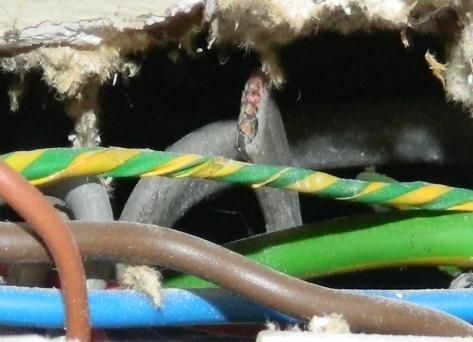
165 Appendix D Photographs Samples 148
INSPECTION AND TESTING OF ELECTRICAL INSTALLATIONS: RESIDUAL CURRENT DEVICES
 INSPECTION AND TESTING OF ELECTRICAL INSTALLATIONS: RESIDUAL CURRENT DEVICES [The basis of this article was first published in Wiring Matters in issue 15, Summer 2005 and reflected the requirements of
PERIODIC ELECTRICAL TESTING POLICY
 PERIODIC ELECTRICAL TESTING POLICY Originator: Policy and Strategy Team Approval date: 19 July 2016 Review date: d July 2017 1 Introduction 1.1 1.2 Pine Court Housing Association (PCHA) treats the health
Contents The IET Regulations, BS 7671, and this Guide 1.1 The need for this Electrician s Guide 1.2 The IET Regulations BS 7671
 Contents 1 The IET Regulations, BS 7671, and this Guide 1 1.1 The need for this Electrician s Guide 1 1.2 The IET Regulations BS 7671 2 1.2.1 International basis 2 1.2.2 The Seventeenth Edition 3 1.2.3
Guide to Membership Assessments
 Issue 10 July 2008 Guide to Membership Assessments 1. Introduction This guide is intended to assist companies in preparing for an assessment visit by SELECT. It supplements the SELECT Assessment Criteria
Periodic Electrical Testing Policy
 Periodic Electrical Testing Policy Originator: Executive Management Team Approval Date: Policy and Strategy Team 18 July 2017 Review date: July 2018 1 Introduction 1.1 1.2 OVH treats the health and safety
Allianz Engineering Inspection Services Ltd. Electrical Services. Product Information
 Allianz Engineering Inspection Services Ltd Electrical Services Product Information Electrical Testing and Inspection Services The Electricity at Work Regulations (EaWR) states that all electrical systems
Systems of inspecting the existing building and the procedures of auditing engineering plans. M. Mostafa
 Systems of inspecting the existing building and the procedures of auditing engineering plans M. Mostafa 2 Agenda 1. Introduction 2. Why inspection? 3. Initial Verification 4. Periodic verification 5. Reference
BUSINESS PLAN CEN/TC 305 POTENTIALLY EXPLOSIVE ATMOSPHERES EXPLOSION PREVENTION AND PROTECTION EXECUTIVE SUMMARY
 BUSINESS PLAN CEN/TC 305 POTENTIALLY EXPLOSIVE ATMOSPHERES EXPLOSION PREVENTION AND PROTECTION CEN/TC 305 Business Plan Page: 1 Business environment, benefits and priorities EXECUTIVE SUMMARY CEN/TC 305
Fire Safety Management Audit Specification August 2017
 Fire Safety Management Audit Specification August 2017 Membership Training Qualifications Audit and Consultancy Policy and Opinion Awards Contents Page 1 Introduction to the Fire Safety Management Audit
NATIONAL RULES FOR ELECTRICAL INSTALLATIONS IN POTENTIALLY EXPLOSIVE ATMOSPHERES. ET 105:2001 (Second Edition)
") NATIONAL RULES FOR ELECTRICAL INSTALLATIONS IN POTENTIALLY EXPLOSIVE ATMOSPHERES ET 105:2001 (Second Edition) Consolidated Amendments, Corrigenda and Errata 01/2010 Introduction When ET 105:2001 was originally
NATIONAL RULES FOR ELECTRICAL INSTALLATIONS IN POTENTIALLY EXPLOSIVE ATMOSPHERES ET 105:2001 (Second Edition) Consolidated Amendments, Corrigenda and Errata 01/2010 Introduction When ET 105:2001 was originally
Electrical Management
 5 WHS PROCEDURE P23-01 Page 1 of 9 Issue: 2 1. Intent The Salvation Army Australia Eastern Territory (TSA-AUE) is committed to the provision of a safe, healthy and injury free environment within the mission
Electrical Safety Policy
 Electrical Safety Policy By acting with a business head and social heart, together we achieve our mission to enhance life chances by helping people to fulfil their potential and live better, more independent
Table of Contents for the REGULATION (EU) 2017/745 OF THE EUROPEAN PARLIAMENT AND OF THE COUNCIL of 5 April 2017
 2017/745 OF THE EUROPEAN PARLIAMENT AND OF THE COUNCIL of 5 April 2017") Chapter I o Scope and definitions Article 1 Subject matter and scope 13 Article 2 Definitions 15 Article 3 Amendment of certain definitions 20 Article 4 Regulatory status of products 20 Chapter II o Making
Chapter I o Scope and definitions Article 1 Subject matter and scope 13 Article 2 Definitions 15 Article 3 Amendment of certain definitions 20 Article 4 Regulatory status of products 20 Chapter II o Making
Guide to: 17 th Edition Consumer Units
 Guide to: 17 th Edition Consumer Units Introduction For well over one hundred years the Wiring Regulations have provided the rules which must be followed to make sure that electrical installations are
3. RCCB (residual current operated circuit-breaker without integral overcurrent protection)
") RESIDUAL CURRENT DEVICE (RCD) - Contents 1. Introduction 2. General 3. RCCB (residual current operated circuit-breaker without integral overcurrent 4. RCBO (residual current operated circuit-breaker with
RESIDUAL CURRENT DEVICE (RCD) - Contents 1. Introduction 2. General 3. RCCB (residual current operated circuit-breaker without integral overcurrent 4. RCBO (residual current operated circuit-breaker with
RRC SAMPLE MATERIAL MANAGING FIRE SAFETY LEARNING OUTCOMES
 MANAGING FIRE SAFETY LEARNING OUTCOMES On completion of this element, you should be able to demonstrate understanding of the content by applying what you have learnt to familiar and unfamiliar situations.
Health and Safety Policy. Version Author Revisions Made Date 1 Colin Campbell First Draft March 2014
 Fire Safety Policy Originator name: Section / Dept: Implementation date: Clive Parkinson Health & Safety March 2014 Date of next review: March 2017 Related policies: Health and Safety Policy Policy history:
Amendment Number 3 of BS how it might affect you
 Amendment Number 3 of BS7671 2008 - how it might affect you Geoff Cronshaw provides us with a look ahead at the proposals of Amendment 3 to BS 7671:2008 IET Wiring Regulations and the resulting changes
Protocol between Local Housing Authorities and Fire and Rescue Authorities to improve fire safety
 Protocol between Local Housing Authorities and Fire and Rescue Authorities to improve fire safety Foreword by Communities and Local Government Ministers It is always a priority to ensure safety from the
NOTTINGHAM CITY HOMES
 APPENDIX 1 NOTTINGHAM CITY HOMES FIRE SAFETY POLICY 2013/14 Draft for Board Uncontrolled when printed Page 1 of 14 DOCUMENT CONTROL Identification and Approval Status Document Title: Nottingham City Homes
Requirements for Electrical Installations
 BRITISH STANDARD BS 7671:2008 + Amendment 1:2011 (Corrigendum June 2013) Requirements for Electrical Installations IET Wiring Regulations Seventeenth Edition ISBN-13: 978-1-84919-730-4 BS 7671 Requirements
Non-domestic gas installations (Edition 2)
") Irish Standard I.S. 820:2010 Non-domestic gas installations (Edition 2) NSAI 2010 No copying without NSAI permission except as permitted by copyright law. I.S. xxx: Irish Standard national specification
Irish Standard I.S. 820:2010 Non-domestic gas installations (Edition 2) NSAI 2010 No copying without NSAI permission except as permitted by copyright law. I.S. xxx: Irish Standard national specification
Electrical Safety Policy and Management System
 TITLE: PAGE: 1 OF 14 Housing Solutions Limited Electrical Safety Policy and Management System Page 1 of 15 TITLE: PAGE: 2 OF 14 FOREWORD This document details the system for the management of electrical
The Gas Safety (Installations and Use) Regulations 1998.
 Regulations 1998.") GAS SAFETY PROCEDURE December 2016 Purpose and Scope: This procedure sets out the arrangements and responsibilities for managing gas safety within buildings owned or managed by Tai Calon Community Housing
GAS SAFETY PROCEDURE December 2016 Purpose and Scope: This procedure sets out the arrangements and responsibilities for managing gas safety within buildings owned or managed by Tai Calon Community Housing
Extension of Registered Gas Installer Scheme to include Non-Domestic Gas Works
 Extension of Registered Gas Installer Scheme to include Non-Domestic Gas Works Information Paper Reference: CER/16373 Date Published: 15/12/2016 Closing Date: NA Executive Summary The CER has decided to
The Legal Obligations of Employers to Maintain all Electrical Installations in a Safe Condition
 The Legal Obligations of Employers to Maintain all Electrical Installations in a Safe Condition Issued in the interests of safety by The Legal Obligations of Employers to Maintain all Electrical Installations
Emergency Lighting. This is a free 7 page sample. Access the full version online. Irish Standard I.S. 3217:2008
 Irish Standard I.S. 3217:2008 Emergency Lighting NSAI 2008 No copying without NSAI permission except as permitted by copyright law. Incorporating amendments/corrigenda issued since publication: This document
EDA Scottish Section Regional Business Forum
 EDA Scottish Section Regional Business Forum 1 The trade association for Electrical Contractors in Scotland Founded in 1900 as the Electrical Contractors Association of Scotland Over 1200 members SELECT
Building Standards Division. Whisky Maturation Warehouses Storage Buildings (Class 1) Automatic Fire Suppression Systems
 Automatic Fire Suppression Systems") Building Standards Division Whisky Maturation Warehouses Storage Buildings (Class 1) Automatic Fire Suppression Systems Crown Copyright 2015 Produced by the Buildings Standards Division February 2015 Version
Building Standards Division Whisky Maturation Warehouses Storage Buildings (Class 1) Automatic Fire Suppression Systems Crown Copyright 2015 Produced by the Buildings Standards Division February 2015 Version
West Yorkshire Fire & Rescue Authority. Fire Protection Policy
 West Yorkshire Fire & Rescue Authority Fire Protection Policy Risk Based Inspection Program 2017-2020 West Yorkshire Fire & Rescue Service Oakroyd Hall Birkenshaw Bradford BD11 2DY Date Issued: 28/03/2018
Record of Amendments. Version Date Amendment Section/page affected
 Industry support for effective compliance BTHA Guidance - The Low Voltage Directive (LVD) Directive 2014/35/EU On the harmonisation of the laws of the Member States relating to the making available on
Fire Safety Policy Date: 0
 Fire Safety Policy Date: 0 Policy Preparation & Introduction This document format has been produced by Firesafe Solutions (UK) Ltd to aid managers, tenants and others responsible for fire safety in their
Fire prevention and protection
 Fire prevention and protection The Fire Service College With over 40 years experience, the Fire Service College is a leading organisation for fire prevention, protection and response, providing assessed,
Training, Assessment, Consultants for Hazardous & Industrial Areas
 Training, Assessment, Consultants for Hazardous & Industrial Areas EPIT provides specialist training, assessment and consultancy services for engineers working in hazardous and industrial environments.
Requirements for Electrical Installations
 BRITISH STANDARD BS 7671:2018 Corrigendum (December 2018) Requirements for Electrical Installations IET Wiring Regulations Eighteenth Edition The Institution of Engineering and Technology and BSI NO COPYING
Course outline: 442 Capstone G105A UEENEEG105A - Verify compliance and functionality of low voltage general electrical installations
 RTO Code 41319 Course outline: 442 Capstone G105A UEENEEG105A - Verify compliance and functionality of low voltage general electrical installations Qualification: Applicable to: Unit of competency: Related
Your specialist partner for total electrical compliance. Electrical Testing
 Your specialist partner for total electrical compliance Electrical Testing "To achieve compliance with the legal requirements of the Electricity at Work Regulations 1989 requires proof that an electrical
HazLoc Essential Guides:
 HazLoc Essential Guides: Intertek Deeside Lane, Chester, CH1 6DD UK hazloc@intertek.com 01244 882590 www.intertek-hazloc.com Introduction This white paper aims to clarify ATEX Technical Files. As a Notified
Qualification Specification Highfield Level 1 Award in the Principles of Fire Safety Awareness (RQF)
") Qualification Specification Highfield Level 1 Award in the Principles of Fire Safety Awareness (RQF) Qualification Number: 603/1564/7 Version 1.1 July 2017 Copyright 2017 HABC Ltd. All rights reserved
Qualification Specification Highfield Level 1 Award in the Principles of Fire Safety Awareness (RQF) Qualification Number: 603/1564/7 Version 1.1 July 2017 Copyright 2017 HABC Ltd. All rights reserved
AS/NZS 3190:2011 AS/NZS
 AS/NZS 3190:2016 Australian/New Zealand Standard Approval and test specification Residual current devices (currentoperated earth-leakage devices) Superseding AS/NZS 3190:2011 AS/NZS 3190:2016 AS/NZS 3190:2016
Understanding and implementing an electrical safety regime in your organisation. Dispelling the myths and promoting a risk-based approach
 Understanding and implementing an electrical safety regime in your organisation Dispelling the myths and promoting a risk-based approach Presented by: Richard Slade Who are we? Market leaders in the manufacture
Fire prevention and protection
 Fire prevention and protection The Fire Service College With over 40 years experience, the Fire Service College is a leading organisation for fire prevention, protection and response, providing assessed,
NHS Tayside. Fire Safety Policy
 NHS Tayside Fire Safety Policy Policy Manager Mark Anderson, Head of Property Policy Group Fire Safety Policy Review Group Policy Established Last Updated April 2014 Policy Review Period/Expiry April 2017
The New EMC Directive 2004/108/EC
 The New EMC Directive 2004/108/EC In the process of this review I have tried to spell out in words what is often referred to as a section number while also keeping to location information as used in the
Kings Fire Safety Policy
 Kings Fire Safety Policy All Kings policies will be ratified by the Board of Directors and signed by the Chairperson. Each policy will be co-signed by the principal of each school. Review dates will be
Fire risk management plan. MH/05/Revised/06/17
 Fire risk management plan MH/05/Revised/06/17 1 1. Scope This policy applies to fire safety arrangements in all workplaces, common areas of residential premises and any other premises managed and/or owned
9/7/2010. Chapter , The McGraw-Hill Companies, Inc. AND BONDING. 2010, The McGraw-Hill Companies, Inc.
 Chapter 1 GROUNDING AND BONDING 1 Proper grounding practices protect people from the hazards of electric shock and ensure the correct operation of overcurrent protection devices. Grounding is the intentional
FIRE SAFETY POLICY LEEDS METHODIST MISSION. Oxford Place Centre
 FIRE SAFETY POLICY LEEDS METHODIST MISSION Oxford Place Centre P a g e 2 8 Version Draft 1 Name of responsible (ratifying) committee Leeds Methodist Mission Council Date ratified Document Manager (job
NZQA registered unit standard version 1 Page 1 of 5. Install fixed gas detection apparatus in hazardous areas
 Page 1 of 5 Title Install fixed gas detection apparatus in hazardous areas Level 4 Credits 2 Purpose This unit standard covers the installation, calibration, and response checking of fixed gas detection
AS/NZS IEC :2013
 AS/NZS IEC 61347.2.13:2013 (IEC 61347-2-13, Ed.1.0 2006, MOD) Australian/New Zealand Standard Lamp controlgear Part 2.13: Particular requirements for d.c. or a.c. supplied electronic controlgear for LED
(1135/2016) Translation from Finnish Legally binding only in Finnish and Swedish Ministry of Economic Affairs and Employment, Finland
 Translation from Finnish Legally binding only in Finnish and Swedish Ministry of Economic Affairs and Employment, Finland") Translation from Finnish Legally binding only in Finnish and Swedish Ministry of Economic Affairs and Employment, Finland Electrical Safety Act (1135/2016) By decision of Parliament, the following is enacted:
Translation from Finnish Legally binding only in Finnish and Swedish Ministry of Economic Affairs and Employment, Finland Electrical Safety Act (1135/2016) By decision of Parliament, the following is enacted:
CE marking & your legal obligations
 CE marking & your legal obligations This presentation is intended to provide a practical approach guide to what you need to know about the CE marking requirements for electrical and electronic equipment
Fault Current Monitoring in Electrical Installations
 Fault Current Monitoring in Electrical Installations Foundations, Applications and Methods of Measuring Residual Current in AC and DC Systems - With Residual Current Monitors (RCMs) according to IEC 62020
HEALTH, ENVIRONMENT AND SAFETY MANAGEMENT FOR FACILITIES MANAGERS COURSE OUTLINE
 The HES for Facilities Management course addresses the fundamentals of the Occupational Health and Safety Act and its implications to ensure a safe working environment for employees, contractors and stakeholders
QUALIFICATIONS AND CREDIT FRAMEWORK (QCF) LOGIC CERTIFICATION LIMITED (LCL) QUALIFICATION SPECIFICATION
 LOGIC CERTIFICATION LIMITED (LCL) QUALIFICATION SPECIFICATION") QUALIFICATIONS AND CREDIT FRAMEWORK (QCF) LOGIC CERTIFICATION LIMITED (LCL) QUALIFICATION SPECIFICATION LEVEL 4 CERTIFICATE IN GAS SAFETY MANAGEMENT IN RESIDENTIAL PREMISES (601/0956/8) 1.0 Area and scope
QUALIFICATIONS AND CREDIT FRAMEWORK (QCF) LOGIC CERTIFICATION LIMITED (LCL) QUALIFICATION SPECIFICATION LEVEL 4 CERTIFICATE IN GAS SAFETY MANAGEMENT IN RESIDENTIAL PREMISES (601/0956/8) 1.0 Area and scope
FIRE SAFETY POLICY. Approval Approved by: University Court Date: March 28 th 2017
 Date: March 2017 Page 1 of 12 FIRE SAFETY POLICY Approval Approved by: University Court Date: March 28 th 2017 Page 1 of 12 Date: March 2017 Page 2 of 12 UNIVERSITY OF ABERDEEN FIRE SAFETY POLICY Contents
The New EMC Directive 2004/108/EC
 The New EMC Directive 2004/108/EC In the process of the review I have tried to spell out in words what is often referred to as a section number. This helps reduce the need to flip pages as one reads this.
Session Four Functional safety: the next edition of IEC Mirek Generowicz Engineering Manager, I&E Systems Pty Ltd
 Abstract Session Four Functional safety: the next edition of IEC 61511 Mirek Generowicz Engineering Manager, I&E Systems Pty Ltd The functional safety standard IEC 61511 provides a framework for managing
FIRE SAFETY POLICY Revised March 2013
 FIRE SAFETY POLICY Revised March 2013 CONTENTS Page No 1.0 Statement of Intent 1 2.0 Fire Safety Accountability Structure 2 3.0 Roles and Responsibilities 3 4.0 Fire Safety Management 7 5.0 Fire Risk Assessment
Fire Certificate. An issue of Maintenance from the Technical and Legal perspective
 Fire Certificate An issue of Maintenance from the Technical and Legal perspective Historically, fire safety regulation for buildings in Malaysia focused on the design and construction of adequate life
ELECTRONIC SECURITY THEORY/REGULATIONS EXAMINATION 19 November 2011
 Candidate Code No. ESAI 27 For Board Use Only Result Date Result Date Int ELECTRONIC SECURITY THEORY/REGULATIONS EXAMINATION 19 November 2011 QUESTION AND ANSWER BOOKLET Time Allowed: 3 Hours INSTRUCTIONS
Achieve Success with European Medical Device Commercialization. By Russ King
 Achieve Success with European Medical Device Commercialization By Russ King Achieve Success with European Medical Device Commercialization Given the complexity of the FDA s regulatory pathway, many medical
INTERNATIONAL STANDARD
 INTERNATIONAL STANDARD IEC 60364-4-44 Edition 1.1 2003-12 Edition 1:2001 consolidated with amendment 1:2003 Electrical installations of buildings Part 4-44: Protection for safety Protection against voltage
INTERNATIONAL STANDARD
 INTERNATIONAL STANDARD IEC 60364-4-41 Fourth edition 2001-08 GROUP SAFETY PUBLICATION Electrical installations of buildings Part 4-41: Protection for safety Protection against electric shock This English-language
REGULATORY REFORM (FIRE SAFETY) ORDER 2005 FIRE EMERGENCY PLAN
 ORDER 2005 FIRE EMERGENCY PLAN") REGULATORY REFORM (FIRE SAFETY) ORDER 2005 FIRE EMERGENCY PLAN This Emergency Plan has been developed following fire risk assessments of the relevant building. The purpose of the Plan is to ensure the
REGULATORY REFORM (FIRE SAFETY) ORDER 2005 FIRE EMERGENCY PLAN This Emergency Plan has been developed following fire risk assessments of the relevant building. The purpose of the Plan is to ensure the
User Information Sheet 008 : 2010
 User Information Sheet 008 : 2010 Formerly UIS008, July 2009 ELECTRICAL INSTALLATIONS ASSOCIATED WITH BULK LPG INSTALLATIONS 1. Introduction This Information Sheet describes some of the principles and
CO-ORDINATION OF NOTIFIED BODIES PPE Regulation 2016/425 RECOMMENDATION FOR USE
 CO-ORDINATION OF NOTIFIED BODIES PPE Regulation 2016/425 PPE-R/00.017 Version 2 RECOMMENDATION FOR USE Number of pages: 5 Approval stage : Approved on : Origin : Horizontal Committee, C2D Ad hoc group
Safety Systems Review Retail Guidance and specification Version
 Systems Review Retail Guidance and specification Version 1 2014 Membership Training Qualifications Audit and Consultancy Policy and Opinion Awards Contents Page Systems Review 1 1 Specification for Systems
FIRE SAFETY POLICY June 2014
 FIRE SAFETY POLICY June 2014 Policy Title Fire Safety Policy Reference Number Corpo11/002 Implementation Date June 2014 1 st Review Review Date June 2017 Responsible Officer Director of Performance and
Guide to Gate Safety Legislation & the Machinery Directive
 Guide to Gate Safety Legislation & the Machinery Directive Guide to Gate Safety Legislation & Machinery Directive Gate Safety in the UK market In June 2010 the tragic deaths of 2 young children in separate
EUROPUMP ATEX Guideline Part II
 EUROPEAN ASSOCIATION OF PUMP MANUFACTURERS ASSOCIATION EUROPÉENNE DES CONSTRUCTEURS DE POMPES EUROPÄISCHE VEREINIGUNG DER PUMPENHERSTELLER EUROPUMP ATEX Guideline Part II Application of the EC-Guidelines
Compilation of regulatory approaches used in various countries. Information received by the Secretariat through a survey in 2009
 Compilation of regulatory approaches used in various countries Information received by the Secretariat through a survey in 2009 At its seventeenth session, the Working Party mandated the Sectoral Initiative
Electrical Safety Program
 Electrical Safety Program Developed by: The Office of Environmental Health and Safety June, 2010 Table of Contents Introduction 3 Scope..3 Definitions.3-5 CSU Electrical Shop...5 Responsibilities.5-6 Employees.....5
Australian/New Zealand Standard
 AS/NZS 3760:2003 (Incorporating Amendment No. 1) AS/NZS 3760:2003 Australian/New Zealand Standard In-service safety inspection and testing of electrical equipment AS/NZS 3760:2003 This Joint Australian/New
Record of Amendments. Version Date Amendment Section/page affected
 Industry support for effective compliance BTHA Guidance on The Restriction Of The Use Of Certain Hazardous Substances In Electrical and Electronic Equipment (recast) (RoHS) Directive 2011/65/EU Comparison
To seek Cabinet approval of the Council s Fire Safety Policy. It is proposed that Cabinet approves the Fire Safety Policy.
 NORTH AYRSHIRE COUNCIL Cabinet 1 May 2018 Title: Purpose: Recommendation: Fire Safety Policy To seek Cabinet approval of the Council s Fire Safety Policy. It is proposed that Cabinet approves the Fire
COMMISSION DELEGATED REGULATION (EU) /... of XXX
 /... of XXX") EUROPEAN COMMISSION Brussels, XXX [ ](2016) XXX draft COMMISSION DELEGATED REGULATION (EU) /... of XXX amending Delegated Regulations (EU) No 1059/2010, (EU) No 1060/2010, (EU) No 1061/2010, (EU) No 1062/2010,
EUROPEAN COMMISSION Brussels, XXX [ ](2016) XXX draft COMMISSION DELEGATED REGULATION (EU) /... of XXX amending Delegated Regulations (EU) No 1059/2010, (EU) No 1060/2010, (EU) No 1061/2010, (EU) No 1062/2010,
Guide to Gate Safety Legislation & the Machinery Directive. In Association with:
 Guide to Gate Safety Legislation & the Machinery Directive In Association with: Tel: 0845 054 5070 asosafety@egduk.com Guide to Gate Safety Legislation & Machinery Directive Gate Safety in the UK market
BEST VALUE PERFORMANCE INDICATORS CONSULTATION: INSURERS VIEWS ON ITS IMPLICATIONS A RESPONSE BY THE ASSOCIATION OF BRITISH INSURERS
 BEST VALUE PERFORMANCE INDICATORS CONSULTATION: INSURERS VIEWS ON ITS IMPLICATIONS A RESPONSE BY THE ASSOCIATION OF BRITISH INSURERS The Association of British Insurers (ABI) is the trade association for
INTERNATIONAL STANDARD
 INTERNATIONAL STANDARD IEC 61511-2 First edition 2003-07 Functional safety Safety instrumented systems for the process industry sector Part 2: Guidelines for the application of IEC 61511-1 Reference number
Fire safety policy. Contents. This policy was approved by the Trustees on 3 September 2015 and will be reviewed not later than every 3 years.
 Fire safety policy This policy was approved by the Trustees on 3 September 2015 and will be reviewed not later than every 3 years. Contents 1. Policy principles 2 2. Statutory and Regulatory Framework
For the Design, Installation, Commissioning & Maintenance of Fire Detection and Fire Alarm Systems
 BAFE Scheme: SP203-1 Version 7.1: January 2019 FIRE SAFETY REGISTER Fire Protection Industry Scheme, Reference SP203-1 For the Design, Installation, Commissioning & Maintenance of Fire Detection and Fire
Fire Safety Policy 29/09/2017. Holme Grange School Whole School Policy Including EYFS. Fire Safety Policy
 Holme Grange School Whole School Policy Including EYFS Fire Safety Policy This document details the school s policy on fire safety in operation at Holme Grange School. The document is split into a number
Fire Risk Management Policy. UK September 2017
 UK September 2017 5 & 7 Diamond Court, Opal Drive, Eastlake Park, Fox Milne, Milton Keynes MK15 0DU, T: 01908 396250, F: 01908 396251, www.cognitaschools.co.uk Registered in England Cognita Limited No
Alan Wells Technical and Standards Director Certsure LLP trading as NICEIC
 Introduction Alan Wells Technical and Standards Director Certsure LLP trading as NICEIC Who are Certsure? Where do we come from? 1923 - A National Register created 1956 - NICEIC established as a Charity
Information Bulletin
 Consideration of emergency response in Alternative Solutions Version 1 Approved for release May 2015 1.0 Purpose statement The purpose of this document is to increase awareness and consideration of the
Loss Prevention Standard
 Loss Prevention Standard LPS 1500: Issue 2.1 provide compartmentation in buildings This standard defines the requirements for companies installing fire resisting compartment systems approved by LPCB to
New requirements for IEC best practice compliance
 New requirements for IEC 61511 best practice compliance Proof testing and a SIL study may no longer be enough by Sven Grone Schneider Electric Safety Services Practice Leader Executive summary Since its
SELF PRESERVATION SOCIETY By Jim Creak
 SELF PRESERVATION SOCIETY By Editor of the Means of Escape Magazine and Chairman of The Health & Safety Signs Association. w w w. m e a n s - of- e s c a p e. c o m Agenda Regulatory Reform Fire Safety
CE MARKING OF WOOD-BASED PANELS
 28 Market Place Grantham Lincolnshire NG31 6LR Tel: 00 44 (0) 1476 563707 Fax: 0044 (0) 1476 579314 e-mail: wpif.panelboards@virgin.net WOOD PANEL INDUSTRIES FEDERATION CE MARKING OF WOOD-BASED PANELS
An overview of the main proposals in BS th Edition. Electrical Contractors Association
 An overview of the main proposals in BS 7671 17 th Edition Electrical Contractors Association Why have Regulations Behold the electrician standing there. Soot, soil & verdigris defile his greasy hair.
DOMESTIC SMOKE ALARMS AND SPRINKLERS. Introduction. Materials and methods. Frank SWANN 1. Legislative impact. Review article
 DOMESTIC SMOKE ALARMS AND SPRINKLERS Frank SWANN 1 Abstract: Key words: Making further inroads into the reduction of fire deaths and injuries in the home is a clear ambition of the UK Chief Fire Officers
EUROPEAN COMMISSION DIRECTORATE-GENERAL FOR HEALTH AND FOOD SAFETY
 Ref. Ares(2017)2066048-21/04/2017 EUROPEAN COMMISSION DIRECTORATE-GENERAL FOR HEALTH AND FOOD SAFETY Health and food audits and analysis DG(SANTE) 2016-8748 - MR FINAL REPORT OF AN AUDIT CARRIED OUT IN
AS/NZS 3820:2009 (Incorporating Amendment 1) Essential safety requirements for electrical equipment
 Essential safety requirements for electrical equipment") AS/NZS 3820:2009 (Incorporating Amendment 1) Essential safety requirements for electrical equipment AS/NZS 3820:2009 This Joint Australian/New Zealand Standard was prepared by Joint Technical Committee
AS/NZS 3820:2009 (Incorporating Amendment 1) Essential safety requirements for electrical equipment AS/NZS 3820:2009 This Joint Australian/New Zealand Standard was prepared by Joint Technical Committee
Fire Safety Policy. Document Author: Director of Estates, Fleet & Facilities Management
 Fire Safety Policy Document Author: Director of Estates, Fleet & Facilities Management Date Approved: January 2018 Document Reference Fire Safety Policy January 2020 Version V: 2.1 Responsible Committee
REGULATED QUALIFICATIONS FRAMEWORK (RQF) LOGIC CERTIFICATION LIMITED (LCL) QUALIFICATION SPECIFICATION
 LOGIC CERTIFICATION LIMITED (LCL) QUALIFICATION SPECIFICATION") REGULATED QUALIFICATIONS FRAMEWORK (RQF) LOGIC CERTIFICATION LIMITED (LCL) QUALIFICATION SPECIFICATION LEVEL 4 CERTIFICATE IN GAS SAFETY MANAGEMENT IN SOCIAL HOUSING (601/1725/4) 1.0 Area and scope of
REGULATED QUALIFICATIONS FRAMEWORK (RQF) LOGIC CERTIFICATION LIMITED (LCL) QUALIFICATION SPECIFICATION LEVEL 4 CERTIFICATE IN GAS SAFETY MANAGEMENT IN SOCIAL HOUSING (601/1725/4) 1.0 Area and scope of
INTERNATIONAL STANDARD
 INTERNATIONAL STANDARD IEC 60364-6 First edition 2006-02 Low-voltage electrical installations Part 6: Verification This English-language version is derived from the original bilingual publication by leaving
DISTRICT OF PORT HARDY BYLAW A BYLAW TO ESTABLISH AND REGULATE THE DISTRICT OF PORT HARDY FIRE DEPARTMENT
 DISTRICT OF PORT HARDY BYLAW 16-2011 A BYLAW TO ESTABLISH AND REGULATE THE DISTRICT OF PORT HARDY FIRE DEPARTMENT GIVEN THAT the District of Port Hardy wishes to establish a fire department and set procedures
SOCIETY OF FIRE PROTECTION ENGINEERS POSITION STATEMENT P THE ROLE OF THE FIRE PROTECTION ENGINEER IN THE CONSTRUCTION DESIGN PROCESS
 SOCIETY OF FIRE PROTECTION ENGINEERS POSITION STATEMENT P-02-07 THE ROLE OF THE FIRE PROTECTION ENGINEER IN THE CONSTRUCTION DESIGN PROCESS March, 2007 Society of Fire Protection Engineers - 1 - Position
Functional Safety: the Next Edition of IEC 61511
 HazAus2015/1507 Functional Safety: the Next Edition of IEC 61511 Mirek Generowicz Engineering Manager I&E Systems Pty Ltd Level 2, 445 Hay Street Perth WA 6000 Abstract The functional safety standard IEC