Interactive Fire Control Panel IFS7002 four signal loops Instruction Manual
|
|
|
- Hugh Greer
- 5 years ago
- Views:
Transcription


1 Interactive Fire Control Panel IFS7002 four signal loops Instruction Manual Revision 6/01.17
2 Contents 1. Introduction Terminology Function Technical data Physical configuration Fire alarm zones Fire alarm loops Power loop Monitored outputs Relay output for fire conditions Programmable relay output Relay output for fault conditions Performance Indications of registered events Power supply Mains Back up batteries Consumption on back up batteries supply Power supply to external devices Dimensions Weight Contents of delivery General information Access levels Access Level Access Level Access Level Access Level Indications and buttons for control Zone in Coincidence Mode Addressing, initialization, re-initialization Addressing Initialization Re-initialization Operation of the fire control panel Duty Mode Description Indication LED and sound indication Text message Using the keypad Fire condition Instruction Manual Page 2
3 8.1. Description Indication LED and sound indication Text messages Using the keypad Fault Condition Description Indication LED and sound indication Text messages Using the keypad Disabled component Description Indication LED and sound indication Text messages Using the keypad Test Mode Description Indicators LEDs and sound indicators Text messages Using the keypad Information and Control Mode Description Menu Lists Menu Faults Menu Disables Menu Zones in Test Menu Input messages Menu Activated Outputs Screen Panel configuration Menu Panel parameters Menu Loops Menu Zones Menu Device Status Menu Inputs Menu Archive Menu Select Loc/Rem. Control Panel Menu System functions Menu Disables Menu Zones in Test Function Set Clock Function Set Mode Function Check LEDs and Buzzer Menu Set Up Set Up Mode Description Instruction Manual Page 3
4 13.2. Menu Panel configuration Menu Panel parameters Menu Loops Menu Loop parameters Screen List Devices Menu Device parameters Function Check up Function Manual addressing Menu Zones Menu Devices Menus Fire Phase 1 Outputs and Fire Phase 2 Outputs Menu Zone parameters Menu Service Rem. Zones Screen Text message Menu Inputs Screen List of addressable outputs Menu Remove addressable output Menu Add addressable output Screen Outputs activation mode Menu Text message Menu Initialization Function Initialization Function Clean initialization Menu Readdressing Menu Exclude devices Menu Check Menu Checks Menu Monitored outputs Menu Relay outputs Menu Addressable outputs Function Display Menu Buttons Menu New passwords Menu Level Function Level Function Default parameters Function Clear archive Saving the parameters Labour protection requirements Installation and arrangements To mount the fire control panel Periphery devices assembly Mounting periphery devices to monitored outputs Mounting periphery devices to relay outputs Connecting interface devices Global network Local network Connecting addressable fie detectors Power supply connection Fire control panel start up Instruction Manual Page 4
5 17.1. Sequence of start up Clean initialization of loops Clean initialization of loops with automated addressing Clean initialization of loops set to manual addressing Troubleshooting Conditions of operation, storage and transportation Operation and storage Temperature Relative humidity Transportation Warranty Appendixes Instruction Manual Page 5
6 1. Introduction Interactive Fire Control Panel IFS 7002 is an up-to-date, high reliable, multifunctional and versatile device, providing the user with unexpected potential in the design, installation and operation of addressable fire alarm systems. Some of its main features and possibilities are: Adjustment of operating modes and parameters of each fire alarm line via built in keypad; User oriented menu dialogue for easy and convenient operation; LCD for visualization of system checkup and setup modes; Touch-panel contributing to the creation of a dynamic keypad; LEDs indication for early warning of a break down or extreme conditions; Energy independent archive memory saving the event type, date and time, allowing for detailed analysis of the actions of the authorized personnel and of possible problems in the fire protection process of the area; User oriented test modes allowing for a total control of the site protected; Built-in serial interface for connection to other fire control panels of similar or higher level; Built-in serial interface for connection to second level control devices, ability for connection via telephone line and a standard modem; System expansion and functional modification (our goal is to constantly improve the fire alarm equipment features), no additional cabling necessary; Compatible to random installation design, within the range of the available fire control panels resources. All these are realizable via fire control panel s keypad and after a detailed examination of the instructions set herewith. 2. Terminology АDDRESSING the method used for assigning addresses to addressable devices in a fire alarm loop. The addressing can be automated or manual and shall be performed separately for each fire alarm loop (see section 6.4.1). ADDRESSABLE OUTPUT potential or relay output of an addressable executive device included in fire alarm loops. The executive device can be power supplied from the fire alarm loop or from the power supply loop. ADDRESSABLE DEVICE a device included in one of the fire alarm loops that has its own address for communication with the fire control panel. An addressable device can be a fire detector (automatic or manual call point), a conventional line-monitoring module or an input/output module. ASSOCIATED OUTPUT addressable monitored or relay output, user programmed to react upon Fire condition (separately upon Fire condition I and Fire condition II) via selected fire alarm zone. INSPECTION TIME period of time added to the remaining time, before the system proceeds from Fire condition stage I to Fire condition stage II, when button is pressed. Usually, this period of time is long enough for the authorized personnel to check up the indicated premises. The inspection time is user defined and is specified for each zone. PROCEEDING FROM FIRE CONDITION STAGE I TO FIRE CONDITION STAGE II the time is user defined for each zone separately. During the phase Fire condition stage I the remaining time for the selected fire alarm line is indicated on the LCD display. During the remaining time actions can be taken, for example press or. Instruction Manual Page 6
7 DISABLED ZONE a zone that is not controlled for activated fire detectors and fault condition. This condition is user defined. The indication for a disabled zone is common light indication and text messages on the LCD display. DISABLED ADDRESSABLE/MONITORED OUTPUT the addressable/ monitored output is switched off (the executive device can not be activated) and is not monitored for a fault condition. This feature is user defined. The indication for a disabled addressable/monitored output is common light indication and text messages on the LCD display. DISABLED DEVICE the addressable device (a fire detector) is switched off and is not monitored for a fault condition. This feature is user defined. The indication for a disabled device is common light indication and text messages on the LCD display. SHORT CIRCUIT IN A LOOP non-fatal fault condition, entered due to registered current value in a loop, exceeding a threshold value. The threshold value for each loop shall be user defined. ZONE IN TEST a zone set in Test condition by the user. The zone is reset (the fire detectors in fire condition receive a command to clear the condition) periodically every 60 s. The events registered in a zone in Test condition are not saved in the archive and do not trigger the associated outputs or the light and sound signalling. The indication for a zone in Test condition is common light indication. SWITCHED-OFF ADDRESS an address that will be skipped during initialization of a fire alarm loop (see section 6.4.2). The feature allows including devices in the fire alarm loop later, without reassigning addresses to current devices. INITIALIZATION a process during which addresses are being assigned to addressable devices in a fire alarm loop. The initialization can be two types clear initialization and standard initialization (see section 6.4.2). MONITORED OUTPUT a potential output that monitors the serviceability of the connection wires between the fire control panel and the executive device. Follow the special diagram for connection. SHORT CIRCUIT IN A MONITORED OUTPUT non-fatal fault condition, entered due to registered current value in a monitored output, exceeding a threshold value. LOCAL SOUNDER a sounder built-in the fire control panel. NON-FATAL FAULT CONDITION fault condition that allows the fire control panel to continue operation. The indication is common light indication, local sound indication and text messages on the LCD display. ACCESS LEVEL access level to various indications and control functions. LOW BATTERY fatal fault condition due to full discharge of the backup batteries upon interrupted power supply. GROUNDS non-fatal fault condition, due to leakage to a grounded wire. FIRE ALARM ZONE (further on it will be referred as ZONE) logical unification of automatic fire detectors and addressable manual call points, physically allocated in fire alarm loops on random principle. Interactive Fire Control Panel IFS7002 allows for formation of a maximum of 500 zones. Up to 60 fire detectors can be integrated in each zone. FIRE ALARM LOOP (further on it will be referred as LOOP) automatic fire detectors and addressable manual call points and addressable executive devices, physically connected by the means of two-wire connection. The basic configuration of IFS l loops includes 4 fire alarm Instruction Manual Page 7
8 loops; a maximum of 125 devices (addressable fire detectors and/or addressable executive devices) can be integrated into each loop. FIRE CONDITION STAGE I phase 1 of Fire condition; upon activation of automatic fire detector the fire control panel enters Fire condition until the specified time expires. The common and local light indicators, local sound signaling and a text message displayed on the LCD display indicate the phase. FIRE CONDITION STAGE II phase 2 of Fire condition; the fire control panel enters Fire condition stage II when: a) the time for Fire condition stage I has expired or b) upon activation of a manual call point. The common light indicators, local sound signaling and a text message displayed on the LCD display indicate the phase. INTERRUPTED LOOP OR MONITORED OUTPUT non-fatal fault condition due to current value in a loop or in monitored output lower than the threshold value. The user shall define the threshold value separately for each loop. COINCIDENCE MODE mode of operation of the fire alarm zones, that requires activation of at least two automatic fire detectors in a zone so the fire control panel is able to enter Fire condition, phase Fire condition stage I, in this particular zone (see section 6.3). RELAY OUTPUT a relay, potential-free switching outputs provided for controlling external executive devices. POWER LOOP a two-wire connection supplying power to addressable executive devices in case their consumption exceeds the load carrying capacity of the fire alarm loops, which they have been integrated into. IFS7002 has 1 power loop, its load carrying capacity is 1000 ma. SYSTEM ERROR fatal fault condition due to a fault in system s basic component SYSTEM OPERATION the fire control panel executes internal operations to set its registers. This is visualized on the LCD display with a text message for system operations, before the user is allowed to proceed with his work with IFS7002. DEVICE REMOVED non-fatal fault condition due to removed device (addressable fire detector of a specific zone and/or addressable executive device). FATAL FAULT CONDITION fault condition that prevents the fire control panel from continuing its operation. The indication is common light indication, local sound indication and text messages on the LCD display. 3. Function Interactive Fire Control Panel IFS7002 with four signal loops is designed to operate with addressable automatic fire detectors and manual call points. It controls addressable executive devices integrated into fire alarm loops. The addressable executive devices can be power supplied from the fire alarm loop or from a power loop. The panel has outputs provided for integration of external executive devices. 4. Technical data 4.1. Physical configuration 4 fire alarm loops 1 power loop 2 monitored outputs 1 relay outputs for fire condition 1 programmable relay output for fire condition stage I and/or stage II 1 relay output for fault conditions 4.2. Fire alarm zones Maximum number of zones Instruction Manual Page 8
9 Maximum number of fire detectors in a zone Fire alarm loops Maximum number of fire detectors in a loop Connecting line - two-wire shielded Maximum resistance of a loop - 80 Output resistance of a loop - 10 Maximum consumption of a loop - 200mA 4.4. Power loop Connecting line - two-wire Maximum resistance of the loop - 10 Output resistance of the loop Maximum consumption of the loop - 1A 4.5. Monitored outputs Type - potential Еlectrical characteristics - (24±5)V/1A 4.6. Relay output for fire conditions Type - potential free, switching, Electrical characteristics - 3A/125VAC; 3A/30VDC 4.7. Programmable relay output Type - potential free, switching, Electrical characteristics - 3A/125VAC; 3A/30VDC 4.8. Relay output for fault conditions Type - potential free, switching Electrical characteristics - 3A/125VAC; 3A/30VDC 4.9. Performance Control over fire alarm loops and monitored outputs for fault conditions (short circuit and interruption) and automatic reset Detection of removed devices in the loops and automatic reset Ability to set the zones in Coincidence Mode Two phases of Fire condition, programmable time for Fire condition stage I, separately for each zone Option for setting the fire detectors belonging to one zone in Coincidence Mode; Option to prolong the time period for Fire condition stage I with programmable inspection period, specified for each zone Built-in sounder for fire condition one tonal, discontinuous, can be switched off Built-in sounder for fault condition one tonal, discontinuous, can be switched off Built-in real time clock Set of test modes and options for adjustment: Setting the clock; Check ups on light and sound indications; Test of fire alarm zones; Adjustment of outputs and integrated external devices; Programming of parameters and modes of operation; Remote programming of the parameters from distant operator control point; Energy independent archive of registered events with the events type, date and hour up to 2046 events; Interfaces for communication with external devices - CAN 2.0B and RS-232 (directly or via modem) Indications of registered events Light indication - LED Text messages - LCD display, graphic 320 х 240 points, backlit Sound signaling - built-in sounder Power supply Instruction Manual Page 9
10 Mains voltage - 220/230V frequency - 50Hz Back up batteries battery type - lead, gel electrolyte number of batteries - 2 pcs connection - serial connection nominal voltage of the back up battery - 2 х 12V nominal capacity C 20-18Ah extreme discharge voltage - 21V charge voltage - 28,2V Consumption on back up batteries supply at 24V - < 250mA at 26V - < 240mA Power supply to external devices Voltage - (24±5)V Maximum current value (including current of monitored outputs and power loop) - 5А Dimensions Overall dimensions - 493x464x110mm Weight Weight (batteries not included) - 10kg 5. Contents of delivery Fire control panel IFS7002 Resistors 5,6k / 0,25W Jumper for the backup batteries Fuse 4A Fuse 6,3A CD with documentation (Instruction Manual, Service Personnel Instruction Manual) Packing 6. General information The fire control panel is controlled by means of buttons, shown on the touchscreen. Different buttons are active depending on the chosen menu, screen or function. Observe strictly the requirements for operation with the panel in order to ensure its long lasting performance. The function of the stylus (pos. 1, fig.1) is to facilitate and provide the safety operation of the touchscreen of fire control panel IFS7002 and repeater IFS7002R. Tap slightly the stylus point on the displayed button. The self-sticking support pad (pos.2, fig.1) allows it to be stuck in a convenient plce. It is not recommended to use other objects when operating the touchscreen panel as there is a risk to damage it. - 1 pc - 2 pcs - 1 pc - 1 pc - 1 pc - 1 pc - 1 pc 1 2 Instruction Manual Page 10 Fig Access levels 4 levels of access to the variable indications and control functions of IFS7002 are available Access Level 1 All persons who would presumably find out and react to alarm upon fault condition or fire condition have access to level 1.
11 The following actions are accessible: Displaying suppressed messages for Fire condition, Fault condition, Disabled components and Zone in test (see sections 8.3.6, , and ); Entering inspection time period (see section 8.3.1); Forced proceeding from phase Fire condition stage I to phase Fire condition stage II (see section 8.3.3); Suppressing the local sounder (see sections and 9.3.1); Displaying text messages from the inputs (see section ); Displaying program data for the fire control panel (see sections to and ); Displaying the status of the addressable devices in the loops (see section ); Displaying the archive (see section ). All light indicators are visible Access Level 2 The personnel in charge of the fire protection have access to level 2; they shall be authorized and trained to operate the fire control panel in the following conditions: Duty Mode; Fire condition; Fault condition; Disabled component; Information and adjustment. To enter Access level 2 use your password. The following features of the fire control panel are accessible: All features accessible at Level 1; Switching off the outputs, activated upon fire condition (see section 8.3.4); Exit of Fire condition (see section 8.3.5); System functions of the fire control panel (see section 12.3) Access Level 3 Accessible for personnel trained and authorized for: Reconfiguration of specific data of the protected site or of the fire control panel saved in the memory; Maintenance of the fire control panel. This level has two sublevels of access - 3A and 3B. Level 3, sublevel 3A, is accessed through a password entered at Access level 2. At this sublevel the functions for reconfiguration of specific data for the protected site or the fire control panel are accessible (see section 13). Level 3, sublevel 3B is accessed when the fire control panel is opened. The following features are accessible: Replacing a burnt fuse; Connecting fire alarm loops and executive devices Access Level 4 Accessible for personnel trained and authorized by the Producer to repair the fire control panel and to modify the software. Special means are required to enter this level Indications and buttons for control Table 1 gives detail description of the indications for each status, Table 2 presents the basic means for control. Appendix 1 shows the front panel of IFS7002. Table 1 Conditions of the fire control panel All conditions - The fire control panel is power supplied Indication Indicator Power supply continuous green light Instruction Manual Page 11
12 Fire condition Conditions of the fire control panel Fault condition - All faults except for Battery Low Fault condition System error Fault condition - Fault in mains supply Disabled component - Disabled zone, addressable device or monitored output Test condition Fire condition Fault condition - All faults except for Battery Low Fault condition - Low battery Indication Common indicator Fire condition flashing red light Common indicator Fault condition continuous yellow light Indicator System error - continuous yellow light Indicator Fault in mains supply - continuous yellow light Indicator Disabled component - continuous yellow light Indicator Test continuous yellow light Local sounder discontinuous signal: 0.5 s sound, followed by 0.5s break Local sounder discontinuous signal: 1 s sound, followed by 1 s break Local sounder discontinuous signal: 1 s sound, followed by 3 s break 6.3. Zone in Coincidence Mode Coincidence Mode allows for enhanced certainty that a zone has entered Fire condition, phase Fire condition stage I. The mode requires that at least two fire detectors from this zone shall be activated to trigger Fire condition, phase Fire condition stage I in the fire control panel. The Coincidence Mode is not applicable to manual call points. If a manual call point, included in a zone set to Coincidence Mode, responds, the fire control panel enters Fire condition, phase Fire condition stage II in this particular zone. Upon activation of an automatic fire detector from a zone set to Coincidence Mode, but the fire control panel has not entered Fire condition in this zone, then: If no other automatic fire detector is activated, the zone enters Pre-Fire condition; If another automatic fire detector is activated, i.e. the zone is in Pre-Fire condition, then the fire control panel enters Fire condition, phase Fire condition stage I, in this particular zone. Exit from Pre-Fire condition in a zone is done: Upon activation of a second automatic fire detector in the zone (the fire control panel enters Fire condition, phase Fire condition stage I, in this particular zone); Upon activation of a manual call point in the zone (the fire control panel enters Fire condition, phase Fire condition stage II, in this particular zone) On manual operation from the button Reset Fire (password for Access Level 2 is required) the control panel will send command Reset to duty mode to the automatic detector in fire condition. To set a zone in Coincidence Mode you need to appoint the parameter Coincidence Mode for this zone (see section ). While using the Coincidence Mode in a zone, we recommend you to include just one group of automatic fire detectors (minimum 2 fire detectors) in this zone, allocated in one and the same room, so upon activation of any two fire detectors you obtain a firm indication for fire in the room. Instruction Manual Page 12
13 Table 2 Means of control Button Reset Fire Condition of the fire control panel Access level Operation Fire condition Level 2 To exit the Fire condition Button Fire condition stage II Fire condition, phase Fire condition stage I Levels 1 and 2 To force transition to phase Fire condition stage II Button Outputs (no suppressed outputs) or Fire condition Level 2 - upon activated outputs for fire condition to suppress the outputs - if no outputs for fire condition are activated to activate all suppressed outputs (suppressed outputs) Button Inspection Fire condition, phase Fire condition stage I Levels 1 and 2 To add time period for inspection Button Stop Alarm Fire condition and Fault condition (with the exception of Fatal Fault Condition) Levels 1 and 2 To suppress the local sounder Button Menu Duty mode, Fire condition, Fault condition (with the exception of Fatal Fault Condition) Test mode and Disabled component Level 1 To enter Information and Control mode Button Enter Information and Control Mode Level 1 To enter a selected menu Information and Control Mode SetUp Mode Level 2 Level 3А - To enter a selected menu; - To execute a selected command; - To save a modified parameter Button Down Information and Control Mode SetUp Mode Levels 1 and 2 Level 3А To display the next element of the menu Button Up Information and Control Mode SetUp Mode Levels 1 and 2 To display the previous element of the menu Level 3А Instruction Manual Page 13
14 Means of control Condition of the fire control panel Access level Operation Button Exit Information and Control Mode Levels 1 and 2 To exit Information and Control Mode SetUp Mode Level 3А To exit SetUp Mode and reset the system Button Cancel Information and Control Mode SetUp Mode Levels 1 and 2 Level 3А - To exit a function without saving changes in the parameter; the command will not be executed; - To exit the current menu and to move to an upper hierarchy menu Button Change Information and Control Mode SetUp Mode Button Move down Fire condition and Information and Control Mode Button Move up Button Page down SetUp Mode Fire condition and Information and Control Mode SetUp Mode Information and Control Mode Levels 1 and 2 To change an element to its next permissible Level 3А Levels 1 and 2 Next element (if any are available) from the left window Level 3А Levels 1 and 2 Previous element (if any are available) from the left window Level 3А Level 1 Next page from the left window Button Page up Information and Control Mode Level 1 Previous page from the left window Button To the right Button To the left Button Clear С Buttons with digits, characters and symbols Information and Control Mode SetUp Mode Information and Control Mode SetUp Mode Information and Control Mode SetUp Mode Information and Control Mode SetUp Mode Levels 1 and 2 - To move the cursor one position to the right; - Next element (if any are available) from the left window Level 3А To move the cursor one position to the right Levels 1 and 2 - To move the cursor one position to the left; - Next element (if any are available) from the left window Level 3А To move the cursor one position to the left Levels 1 and 2 Level 3А To delete a character pointed by the cursor (if no character is pointed, the first character to the left of the cursor will be deleted) Levels 1 and 2 To insert a character/symbol to the left of the cursor Level 3А Instruction Manual Page 14
15 6.4. Addressing, initialization, re-initialization Addressing The method used for assigning addresses to addressable units in a fire alarm loop is called Addressing. The addressing can be automated or manual and shall be performed separately for each fire alarm loop. In automated addressing the fire alarm loops units obtain addresses according to a strictly specified algorithm and the fire control panel is capable to detect their location later. To be able to operate in automated addressing mode, a fire detector shall meet the following requirements: No short circuit or break up detected; Not more than one branch at a single point, i.e. between two consecutive units; No branches between the fire control panel and the first (the last) unit; No branching of branches. In manual addressing the fire alarm loops units obtain addresses as they are determined by the user. If, while performing manual addressing, the algorithm of the automated addressing is not followed, the fire control panel will not be capable to detect the units location later. The only restriction in manual addressing is explained in section Initialization Initialization is a process during which addresses are being assigned to addressable devices in a fire alarm loop. The initialization can be two types clear initialization and standard initialization: In clear initialization new configuration of the addressable units is entered in the fire alarm loop In standard initialization the fire control panel checks the compliance of the addressable units current configuration with the configuration, entered during the clear initialization. In both types of initialization the switched-off addresses are skipped (in clear initialization of a fire alarm loop in manual addressing mode this shall be ensured by the user). The option allows reserving addresses for units, included later in the loop, without re-assigning the addresses of the current units Clear initialization in automated addressing mode Clear initialization is done in the following cases: Initial start-up of the fire control panel; The fire control panel or an output is being switched on at Set Up, when the default parameters of the control panel are entered; The function Clear initialization is being started at Set Up Mode in such case it is performed only for fire alarm loops which are set to automated addressing. The addressable units in the fire alarm line, detected by the control panel, are addressed in series (consecutively), and their parameters (identification number, type and class) are recorded in the fire control panel Standard initialization in automated addressing mode Standard initialization in automated addressing is done for fire alarm loops set to automate addressing, in the following cases: The fire control panel or an output is being switched on at Set Up, when the addressable units configuration is registered in the control panel (i.e clear initialization has already been done); Start up of the Initialization function, at Set Up Mode (see section ). The location and the parameters (address, identification number, type and class) of the addressable units, detected in the fire alarm loop, are checked for compliance with these recorded in the fire control panel Clear initialization in manual addressing mode Clear initialization in manual addressing mode is performed during start up of the function Manual addressing, at Set Up (see ); it is performed for a selected fire alarm loop only. Any non-addressable units detected in the fire alarm loop obtain addresses previously determined by the user; their parameters (identification number, type and class) are recorded in the control panel. To ensure successful completion of the action, the fire control panel shall not have access to more than two units, located in any line of the loop; i.e. if more than one branch is available at a certain Instruction Manual Page 15
16 point, units without addresses shall be available in two branches only (in the loop and in one branch, or in two branches) Standard initialization in manual addressing mode Standard initialization in manual addressing mode shall be performed for fire alarm loops set to manual addressing, in the following cases: The fire control panel or an output is being switched on at Set Up, when the addressable units configuration is registered in the control panel (i.e clear initialization has already been done); Start up of the Initialization function, in Set Up Mode (see section ). The parameters (address, identification number, type and class) of the addressable units, detected in the fire alarm loop, are checked for compliance with these recorded in the fire control panel. No check up of the units location is done Re-initialization Re-initialization is an address recovery process for an addressable unit that has been removed from the loop and has been installed again. The re-initialization is performed in various ways, depending on the addressing type Re-initialization in automated addressing mode When replacing a removed addressable unit in a fire alarm loop, the fire control panel performs compliance check on unit s location and parameters (identification number, type and class) with these saved in the energy independent memory. A text message, Re-initialization is seen at the display s bottom part. Depending on the result of the compliance check, the control panel performs the following actions: a) Where the control panel is capable to detect synonymously the location of the unit in the loop, and compliance of its parameters with these registered in the energy independent memory is detected, then: The unit is started with its old address in the loop; The fault Removed device is cleared; b) Where the control panel is capable to detect synonymously the location of the unit in the loop, but incompliance of its parameters with these registered in the energy independent memory is detected, then: The unit is started with an address, equal to its location in the loop; Fault condition for incompliance of identification number/type/class is activated; The unit is included in the Service zone (see section 6.5); c) Where the control panel is not capable to detect synonymously the location of the unit in the loop (two or more serial units, that form an area, have been removed, but only some of them are installed again), then : The unit is started with the first unoccupied address in the corresponding area of the loop; Fault condition Device not initialized is activated The unit is included in the Service zone. When the last removed unit is replaced in the loop, the fire control panel will synonymously detect their location. For the last included unit the control panel will perform action a) or b). For the previously included units the control panel will perform the following actions: d) Where the control panel detects compliance of unit parameters with these saved in the energy independent memory: The unit is started with its old address in the loop; Fault conditions Removed device and Device not initialized are cleared; The unit is excluded from the Service zone; e) Where the control panel detects incompliance of unit parameters with these saved in the energy independent memory: The unit is started with an address, equal to its location in the loop; Fault condition for incompliance of identification number/type/class is activated; The unit remains in the Service zone. Instruction Manual Page 16
17 Re-initialization in manual addressing mode When a removed addressable unit is replaced in the fire alarm loop, the fire control panel performs compliance check on the identification number of the replaced unit with the number saved in the energy independent memory, and starts up the unit with its old address Operation of the fire control panel Constructively, the fire control panel consists of two main PC boards base PC board and loops PC board. The base PC board is physically configured with 2 fire alarm loops, power loop, user s voltage, serial interface RS232, CAN1, CAN2, monitored and relayed outputs (Appendix 4). Loops PC board is configured with 2 fire alarm loops and CAN1 (Appendix 4). The two PC boards are factory connected via CAN1. Two connected fire control panels are programmably simulated: - base PC Board, named FireControlPanel LOCAL as master fire control panel with address 1 ; - loops PC Board, named FireControlPanel Dist101 as slave fire control panel with address 101. When IFS7002 is switched on, reset of the system devices and initialization of the addressable devices integrated in the loops are being done addressable devices parameters (address, identification number, type and class) are being verified against these saved in the energy independent memory of the fire control panel. A text message -System operations - is displayed on the LCD. Upon completion of the system operations the fire control panel enters operation mode it monitors the addressable devices (automatic fire detectors, manual call points and executive devices) by consecutively scanning their condition. Simultaneously, a constant control over the loops, the monitored outputs and the voltage for fault conditions is being carried out. The fire control panel IFS7002 operates in seven basic modes: Duty Mode, Fire Condition, Fault Condition, Disabled Component Mode, Test Mode, Information and Control Mode and SetUp: The fire control panel is in Duty mode when is not in any of the rest six modes (see section 7); The fire control panel enters Fire condition when a fire detector is activated inn any zone (see section 8); The fire control panel enters Fault condition when a fault is registered (see section 9); The fire control panel enters Disabled component after manual operation, disabling a certain components has been performed fire alarm zone, addressable unit or controllable output (see section 10); The fire control panel enters Test mode after a manual operation, setting the zone in test (see section 11); The fire control panel enters Information and Control Mode when the main menu is activated in Duty mode, Fire condition, Fault condition (without fatal error), Test condition and Disabled component (see section 12); The fire control panel enters SetUp Mode after activation of submenu Set up, in Information and Control Mode (see section 13); In any moment the fire control panel can be in any of the above conditions/modes, or in a random combination of Fire condition, Fault condition, Disabled component, Test mode and Information and Control mode. Duty Mode and SetUp Mode can not be combined with another mode: the fire control panel enters Duty Mode after all other conditions are exited; when the fire control panel enters SetUp Mode it exits all other conditions. Up to 500 fire alarm zones can be formed in IFS7002. Except for these zones the fire control panel supports two additional zones for each PC board: Service zone (Zone 0) here addressable devices which location in the loop can not be detected synonymously are integrated; Zone 255 here addressable devices not included or that can not be included in a fire alarm zone (addressable output and input devices) are integrated. In Fire condition the relay output for fire condition is always activated ( Rel Fire ). Also, the outputs (relay, controllable and addressable) associated to a corresponding phase of the fire condition for the Instruction Manual Page 17
18 zone in fire, are activated. These outputs can be suppressed and then again activated by manual operation at Access level 2 (see section ). The number of activated addressable units inputs, associated to fire alarm loop is seen on the control panel s display, in the middle of the bottom line. The inputs can be programmed to display text messages and/or to activate addressable outputs. The text messages generated by the activated inputs can be reviewed via the menus of Information and Control Mode (see section ). Addressable outputs, activated by inputs, are in operation only when the fire condition is in Fire condition. However they can not be manually suppressed. When a removed addressable unit is replaced in a loop, the fire control panel re-initializes it. When an automated addressing is set for a certain loop, and the re-initialization is not successful due to reasons explained in b), c) and e), , the following actions can be performed: If units have been involuntarily exchanged, they shall be placed on their proper location; The unit shall be excluded from the Service zone, via Menu Re-addressation (see section ) and the suitable address shall be assigned; The new loop configuration shall be saved through Function Clear Initialization (see section ). When new addressable unit is included in a loop set to automate addressing, (exceeding the total number of addressable units in the loop), the fire control panel assigns a temporary address (message seen in the bottom part of the display - Re-initialization), but ignores it in its operation. To add the unit to the loop configuration the function Clear Initialization shall be activated (see section ). When new addressable unit is added to a loop set to manual addressing, the fire control panel ignores it in its operation. To add the unit to the loop configuration the Function Manual Addressation shall be activated (see section ). When the fire control panel is in Fire condition or in Fault condition or in a combination of one of these, the lighting of the display is constantly on, until you press button Stop alarm (with the exception of these fault conditions Battery low, discharged batteries due to interruption of mains supply, and Fault in mains supply). Upon Battery low the lighting of the display is constantly off. In all other cases the lighting is extinguished 3 min after the last pressing of any button on the display. 7. Duty Mode 7.1. Description The fire control panel is in Duty Mode, when it is not in any other of the rest 6 possible conditions Indication LED and sound indication In Duty Mode the green LED indicator is activated Text message The display shows the logo of the company-producer, information on the current local time and the mode of operation of the fire control panel (DAY or NIGHT), the mode of control (Loc control of local panel, or RemX control of a remote panel, where X is the panel s address: (Power supply). The local sounder is off. FIRE CONTROL PANEL IFS UniPOS Ltd Mon 25 Oct :42:23 Mode:DAY Loc ActInp 0000 Instruction Manual Page 18
19 7.3. Using the keypad The only accessible button in Duty Mode is enters Information and Control Mode. 8. Fire condition (Menu). Press it and the fire control panel 8.1. Description The fire control panel enters Fire Condition after a fire detector has been activated in one of the fire alarm zones. In Mode:DAY the condition has two phases Fire condition stage I and Fire condition stage II. The time period for Fire condition stage I is limited and is user programmable, separately for each zone (up to 255 seconds). The period can be prolonged with the Inspection time (see section 8.3.1). When Fire condition stage I in this particular zone expires, the fire control panel enters Fire condition stage II in the same zone. The fire control panel enters Fire condition stage I upon activation of an automatic fire detector and Fire condition stage II - upon activation of a manual call point. In Night Mode the phase Fire condition stage I is ignored. The fire control panel enters Fire condition, phase Fire condition stage II upon activation of a manual call point or of an automatic fire detector. The fire control panel can be in Fire Condition in one or more zones. In the second case, when in Mode:DAY, the fire control panel can be in phase Fire condition stage I in part of the zones, and in phase Fire condition stage II in the rest of the zones. In Fire condition the relay output Rel Fire is activated. The outputs (relay, controllable and addressable) associated to a corresponding phase of the Fire condition for the zones in fire, are also activated. To exit this condition press button at Access level 2 (see section 8.3.5) Indication LED and sound indication In this condition the common light indicator illuminates in red flashing light (Fire condition). The local sounder produces discontinuous signal (0,5s sound, 0,5s break), if the device has not been suppressed by button (Stop Alarm) Text messages Information on zones for which the fire control panel has detected Fire condition is displayed: For this condition the display is divided into three panels. The first panel (the upper one) displays information on zones and on the fire control panel in fire condition. A flashing heading with the text FIRE and the total number of zones in fire condition appear. The panel is subdivided into two text fields, each providing two lines. The first line displays information on the first zone and the fire control panel in fire condition, the second line provides information on the last zone and the fire control panel in fire condition. FIRE CONDITION ZONES IN FIRE: 3 1 Phase 2 Zone 001 Object: LOCAL Zone Phase 1 Zone 002 DIST #101 Time Fire Phase2:120 Zone 002 Devices in Fire TOTAL NUMBER: 4 1 Loop 01 Zone 001 Addr 001 Object: LOCAL Point Loop 02 Zone 003 Addr 001 Object: LOCAL Point Loop 01 Zone 002 Addr 002 Object: DIST #101 Point Faults Total: 00000/0000* Disables Total: 000 Mode:DAY Loc ActInp :11:08 Mon 25 Oct 2010 The first line of each field provides information on the type of the fire condition: the sequence number of the indicated fire condition; Failed Outputs: Disabled Outputs: 000 Instruction Manual Page 19
20 the phase of Fire condition detected by the fire control panel in this particular zone; the zone number; the fire control panel that is in Fire condition (Local or remote control panel). After the remote panel its address is also displayed; the remaining time in seconds before the fire control panel proceeds to phase Fire condition stage II (indicated only in Fire condition stage I). The second line of each field displays a text message for the corresponding zone. If the fire control panel has entered Fire condition in more than two zones, the rest of the text messages for fire condition are suppressed. They can be displayed in the upper field by pressing the buttons on the right side (see section ). The second panel (the middle one) provides information on devices in fire condition. In the head part is displayed the total number of devices in fire condition. The panel itself is subdivided into three text fields, each providing two lines. The upper two-line field displays information on the first device that has detected fire condition; the middle two-line field displays information on the second device in fire condition, the bottom two-line field information on the last device. The first line of each field provides information on the device: the sequence number of the device in fire condition; the fire alarm loop where the device is integrated into; the zone number; the device address in the fire alarm loop; the fire control panel that is in Fire condition (Local or remote control panel). After the remote panel its address is also displayed; The second line of each field displays text messages relevant to this particular device. If more than three devices are activated due to fire condition, the rest of the messages are suppressed. However, they can be displayed in the upper fields, by pressing the buttons on the right side (see section ). The third panel (the bottom one) displays information on the numbers of faults and disables total number and for the outputs (monitored outputs and addressable output devices) Using the keypad Button (Inspection) The button appears on the display when the fire control panel enters phase Fire condition stage I in a new zone; it is extinguished if pressed or if all zones in Fire condition proceed to phase Fire condition stage II. When you press the Inspection button, the remaining time for the zones in Fire condition stage I after which they proceed to Fire condition stage II, is prolonged with user programmed inspection time for each particular zone. The operation can be performed only once for each zone in Fire condition stage I, i.e. it is executed for zones where the remaining time has not already been prolonged with inspection time Button (Stop Alarm) The button appears on the display when the fire control panel enters Fire condition in a new zone or upon registration of a new fault condition; it is extinguished if pressed or if the local sound signaling is suspended (fault conditions suspended and/or the fire control panel exits Fire condition). Press it to turn off the local sounder. Button s operation does not effect and is not cancelled by the following events: When the fire control panel enters Fire condition in a new zone or proceeds from Fire condition stage I to Fire condition stage II, the local sounder is activated for Fire condition only. A new fault condition will trigger the local sounder for Fault condition only Button (Fire condition stage II) The button is seen on the display when the control panel in Fire condition and there are zones in Fire condition stage I. Press the button to force transition from Fire condition stage I to Fire condition stage II. Instruction Manual Page 20
21 Button (Outputs) The button is seen on the display when the control panel is in Fire condition; the button is provided to suppress and enable activation of outputs for fire condition at Access level 2. Addressable outputs, activated by the inputs, can not be suppressed. The button does not affect and is not influenced by the following events: Fire condition in new zone or transition from phase Fire condition stage I to Fire condition stage II will trigger the outputs for fire condition, associated to this zone for a certain fire stage; if any outputs for fire condition are suppressed, the button will have the following graphic: Access Level 1 Press the button at Access level 1 to display a screen where the password is entered: To enter a password use the buttons with digits press a digit and it appears on the place of the cursor _, and the previous text and the cursor itself move one position to the right. Move the cursor to the left or to the right, using buttons. and FIRE CONDITION ZONES IN FIRE: 2 1 Phase 1 Zone 001 Local Time Fire Phase2: 068 Zone Phase 1 Zone 003 Local Zone 003 PASSWORD Enter Password: _ Outputs Time Fire Pase2: С Button С will delete: Any digit under the cursor; Or, if there is no digit under the cursor, then will be deleted the first digit to the left. The length of the password can be 10 symbols maximum. If you press a digit button when the 10- symbol password is entered, the digit will not be inserted. The operation of button is: If a wrong password is entered the entered digits will be deleted and the cursor will appear over the password s first position; If one of the 10 passwords for Access Level 2 or the password for Access Level 3 is entered: Where activated outputs for fire condition are available these outputs will be suppressed; Where activated outputs for fire condition are not available the suppressed outputs will be activated; The fire control panel will exit Information and Control Mode, if it has been operating in a combination of Fire condition mode and Information and Control Mode. To exit the screen press buttons (Exit) or (Cancel). Then, if the fire control panel had been in a combination of Fire condition and Information and Control Mode, it would exit Information and Control Mode Access Level 2 Mode:DAY LOC ActInp :48:32 Mon 25 Oct 2010 Press button at Access Level 2 to: Where activated outputs for fire condition are available these outputs will be suppressed; Where activated outputs for fire condition are not available the suppressed outputs will be activated Exit Information and Control Mode. Instruction Manual Page 21
22 Button ( Reset of fire condition ) The button is seen on the display when the fire control panel is in Fire condition and can be used to force the fire control panel to exit Fire condition at Access Level Access Level 1 Press the button at Access Level 1 to display a screen for password entering Enter the password using the buttons with figures, replacing the cursor position _, and the previously entered text and the cursor itself move one position to the right. Use buttons and to move the cursor to the left or to the right. When pressed, button С will delete: Any figure under the cursor; The figure at the left of the cursor, when no figure is entered under it. Password s maximum length is 10 symbols. When a password with such length has been already entered, no more figures will be accepted. Button has the following effect: If the password is not the correct one the entered figures will be deleted and the cursor will move to the first position; If one of the 10 passwords for Access Level 2 is entered, or a password for Access Level 3: The fire control panel will exit the Fire condition; The fire control panel will exit Information and Control Mode if it was in a combination of Fire condition and Information and Control Mode. To exit the screen, press buttons (Escape) or (Cancel). If the fire control panel has been operating in a combination of Fire condition mode and Information and Control Mode, it will exit Information and Control Mode Access Level 2 FIRE CONDITION ZONES IN FIRE: 2 1 Phase 1 Zone 001 Local Time Fire Phase2: 068 Zone Phase 1 Zone 003 Local Zone 003 PASSWORD Enter Password: _ Outputs Time Fire Pase2: С Mode DAY LOC ActInp :48:32 Mon 25 Oct 2010 Press button at Access Level 2 to exit Fire condition and Information and Control Mode Buttons (Move down) and (Move up) Panel for zones in fire condition Where suppressed messages for zones in fire condition are available they can be displayed in the text fields of the first (upper) panel on the LCD display, by the means of buttons and situated in the panel s right section. Button appears on the display where a message for a zone in Fire condition following the message in the first text field is suppressed. Press the button to display it. When the last suppressed text message for a zone in Fire condition is reached, the button disappears. Button appears on the display where a message for a zone in Fire condition preceding the message in the first text field is suppressed. Press the button to display it. When the first suppressed text message for a zone in Fire condition is reached, the button disappears. Instruction Manual Page 22
23 If a suppressed message for a zone in Fire condition is displayed, 20 s after the last button is pressed, the message for the first zone in fire condition will be automatically restored Panel for devices in Fire condition Where suppressed messages for devices in Fire condition are available, they are displayed in the two text fields of the second (middle) panel, by the meansр of buttons and situated in the right part of the panel. Button is activated if the numbers of the messages in the second and the third field are not consecutive. When you press the button you will display the consecutive messages for devices in Fire condition, in the first and second text fields. Button is activated if the number of the message in the first text field is higher than 1. When you press the button you will display the previous messages for devices in Fire condition, in the first and second text fields of the middle panel Button (Menu) Press the button to enter Information and Control Mode; the mode uses the middle and the bottom panel of the screen for Fire condition Button (Exit) When Fire condition is in combination with Information and Control Mode, press the button and the fire control panel exits Information and Control Mode and on the display appear all three panels of the screen for Fire condition. 9. Fault Condition 9.1. Description The fire control panel enters Fault Condition when any of the events below have been registered: Fatal system error; Battery low backup batteries discharged due to interruption of mains supply; Fault in a processor programme; Fault in a module; Fault in the real time clock; Fault in the external memory; Fault in a loop a short circuit or a break; Loop not initialized; Higher number of devices in the fire alarm loop; Fault in a zone upon detection of fault condition in a device, integrated in the zone; Removed device; Fault condition in a device; Activated isolator of a device; Activated isolator at the Power loop of a device; Contaminated fire detector (for optical detectors ; Communication error Device not initialized (detected new device in a loop); Exchanged devices; Different identification number of a device, Different device type; Different device class; Fault in a monitored output short circuit or break; Fault in the mains supply; Fault in the backup batteries supply; Short circuited ground wire; Fault in the positive supply of the loops; Fault in the negative supply of the loops; Instruction Manual Page 23
24 Fault in external devices supply; Fault condition in communication with a remote fire control panel; Fault condition in the remote fire control panel. Where a fatal system error occurs, the main processor can not continue operation and the fire control panel does not control loops, outputs and other periphery devices. To exit fatal system error you have to cut off the mains supply and to repair the control panel. Battery Low is a fatal non-system error; zones and outputs are not being services. The fire control panel enters a special condition: A discontinuous sound signal is produced - 1s sound, 3s break for at least 1 hour; Only the green LED indicator is illuminated (Power supply). The lighting of the display is extinguished; Only the supply voltages are controlled. The condition is exited automatically 20 s after the mains supply is restored. All other fault conditions are not fatal and switch off some periphery devices. The condition is exited automatically 20 s after the fault is suspended. Upon fault condition Short circuit to ground wire where an element of a monitored output is short circuited, fault condition in the monitored output (break) is also developed. Fault condition is indicated by LEDs indicators and a text message on the LCD display Indication LED and sound indication Where fatal system errors occur the indicators (Fault condition) and (System error) illuminate in continuous yellow light. The local sounder produces continuous signal. Upon Low battery fault condition no LED indicator is illuminated. The local sounder produces discontinuous signal (1 s sound, followed by 3 s break). The lighting of the LCD display is off. All other fault conditions are designated by indicator (Fault condition), illuminating in continuous yellow light. Depending on the specific fault, the following indicators are illuminated too: Upon System error - indicator (System error) in continuous yellow light; Upon Fault in mains supply - indicator (Fault in mains supply) in continuous yellow light. The local sounder produces discontinuous signal (1s sound, 1s break), if not previously suppressed by (Stop Alarm) button Text messages Upon fatal system errors the following information screen is displayed (the first line of the text messages is information intended for the service staff): The screen suppresses all other text indications and can not be suppressed. Fault condition Restart please Instruction Manual Page 24
25 Upon Battery Low condition - full discharge of the backup batteries due to interrupted power supply the following information screen appears: The screen suppresses all other text indications, with the exception of System error message, and can not be suppressed. Battery low For all other fault conditions a table, containing information on the number of fault events and the number of disabled devices is displayed. The first line of the tables left column displays the total number of fault conditions; the first line of the table s right column displays only the number of faults in outputs (monitored outputs and addressable output devices): Faults Total: 00001/00000* Disables Total: 000 FIRE CONTROL PANEL IFS UniPOS Mon 25 Oct :43:13 Failed Outputs: 0000 Disabled Outputs: 000 To display the text message for each fault condition, enter Information and Control Mode (see section ). Mode:DAY LOC ActInp Using the keypad None of the buttons is active upon fatal fault condition. For all other fault condition 2 buttons are being supported. Where the fire control panel operates in combination of other conditions, their buttons are active too Button (Stop Alarm) The button appears on the LCD display where the fire control panel enters fire condition in a new zone or a new fault condition occurs; it disappears if pressed or if the sound signaling is suspended (fault conditions suspended and/or fire control panel exited fire condition) Press the button to switch the local sounder off. The button does not affect and is not influenced by the following events: Fire condition in new zone or transition from phase Fire condition stage I to Fire condition stage II will trigger the local sounder and a signal for fire condition only will be produced; New fault condition will trigger the local sounder and a signal for fault condition only will be produced Button (Menu) Press the button to enter Information and Control Mode. Instruction Manual Page 25
26 10. Disabled component Description The fire control panel enters Disabled component after a manual operation, disabling a specific component a fire alarm zone, addressable device or monitored output. The condition is handled via Information and Control screens (see section ). A disabled zone is not monitored for activated fire detectors or fault condition. A disabled addressable device is not activated (if it is an executive device) and is not monitored for activation (if it is a fire detector) or fault condition. A disabled monitored output is switched off (the executive device is not able to respond) and is not monitored for fault condition. Where disabled zones, disabled addressable devices or disabled monitored outputs are available, the LED indication illuminates and the relevant message is displayed Indication LED and sound indication The condition is indicated by the Common indicator (Disabled component) illuminated in continuous yellow light. No sound signaling is supported for Disabled component condition Text messages If a disabled component is available, a table giving information on the total number of disabled devices and faults appears on the LCD display. The second line of the table s left column displays the total number of disabled components; the second line of the table s right column only the number of disabled outputs (monitored outputs and addressable output devices): Faults Total: 00000/00000* Disables Total: 002 FIRE CONTROL PANEL IFS UniPOS Mon 25 Oct :48:24 Failed Outputs: Disabled Outputs: 001 To display the text message for each fault condition, enter Information and Control Mode (see section ). Mode:DAY LOC ActInp Using the keypad For Disabled component condition 1 active button is supported. Where the fire control panel operates in combination of other conditions, their buttons are active too. Press button 11. Test Mode (Menu) to enter Information and Control Mode Description The fire control panel enters Test Mode through manual operation setting a fire alarm zone to Test Mode. The condition is handled via Information and Control Screens (see section ). Where a fire alarm zone is set to Test Mode, the following changes take effect: Where Fire condition stage I or Fire condition stage II is detected in the zone, sound and LEDs indications, associated addressable, controllable or relay outputs are not triggered; i.e. the fire control panel does not enter Fire Condition; Where Fault condition in a zone is registered, (i.e. fault in any device, integrated in the zone), sound and LEDs indications or the relay output for fault condition are not triggered, i.e. the fire control panel does not enter Fault Condition (with the exception of the isolator of a device in Instruction Manual Page 26
27 the zone, because it would break the integrity of the loop; in this case a fault in the device would be registered, but not fault in the zone); Occurred events (with the exception of triggered isolator in the zone) are not saved in the energy independent memory; The zone is being automatically reset every 60 s (detectors in fire condition receive a command to reset the fire) Indicators LEDs and sound indicators The common indicator for Test Condition Sound signaling is not supported for this condition. (Test) illuminates in continuous yellow light Text messages To display the text messages for fire alarm zones in test condition enter Information and Control Mode (see section ) Using the keypad For Test Condition 1 active button is supported. Where the fire control panel operates in combination of other conditions, their buttons are active too. Press the Menu button 12. Information and Control Mode to enter Information and Control Mode Description Information and Control Mode provides the user with the possibilities to display information associated with the fire control panel, and to enter control data. To enter Information and Control Mode, press button on the screen for Duty Mode, Fire Condition, Fault Condition (with the exception of the screen for fatal error), Test Mode or Disabled component. No specific LEDs or sound indication is provided for Information and Control Mode. Where the fire control panel operates in combination of Information and Control Mode and Fault Condition, button (Stop Alarm) is active too. Where the fire control panel operates in combination of Information and Control Mode and Fire Condition, buttons (Stop Alarm), (Outputs) and (Inspection) are active; and at Access Level 2 is active button (Reset Fire). The screens visualized on the display are organized in a tree structure, containing subordinate menus (Appendix 2а). Transition to a lower hierarchy menu is performed by the means of button (Enter); to revert to an upper hierarchy menu use button (Cancel). To switch between elements of one menu use buttons (Up) and (Down), when the menu is displayed as an ascending window from the bottom left corner of the screen, or use buttons (Move Up) and (Move Down), when the menu is displayed as a panel in the middle of the screen. To exit the condition press button (Exit) or button (Cancel) until you exit the main menu. When you enter Information and Control Mode, transition to the first menu is being carried out. The first menu contains three subordinate menus, requiring separate access levels: Lists Access Level 1; System functions Access Level 2; SetUp Access Level 3. Instruction Manual Page 27
28 12.2. Menu Lists The menu displays detailed information associated to the current state of the fire control panel and the addressable devices, as well as for the configuration and the setup of the control panel. Menu Lists contains the following subordinate menus and information screens; Menu Faults; Menu Disables; Menu Tests; Menu Input messages; Menu Activated outputs; Screen Panel configuration; Menu Panel parameters; Menu Loops; Menu Zones; Menu Devices status; Menu Inputs; Menu Archive; Menu Select Loc/Rem control panel Menu Faults Use the menu to display detailed information for faults in the fire control panel and in addressable devices. Menu Faults contains the following subordinate menus: Меню Total displays information for all fault conditions; Menu Zones displays information only for zones in fault condition; Menu Devices displays information only for devices in fault condition; Menu Outputs displays information only for outputs in fault condition (monitored outputs and addressable output devices); Menu LAN objects to display information for remote control panels (Appendix Interactive Fire Control Panel IFS7002 Local Network Operation). The four subordinate menus have identical layout. If no faults are FIRE CONTROL PANEL IFS detected (or no faults of a specific UniPOS type are detected) the following screen appears: List/Faults/Total NO FAULTS Mode:DAY LOC ActInp :45:23 Thu 28 Oct 2010 Instruction Manual Page 28
29 If faults are detected, the following screen appears: Each message can be displayed in a few lines from 1 to 4. It brings out the following information Text for the type of the fault this information is mandatory; Information for the device (zone if the device is fire detector, loop and address) in case the fault condition is in an addressable device; Text message for the zone visualized if the fault condition is in an addressable fire detector; Text message for the device visualized if the fault condition is in an addressable device. FIRE CONTROL PANEL IFS UniPOS Faults Total: 00003/00001* Failed Outputs: Disables Total: 000 Disabled Outputs: 000 List/Faults/Total Fault in Zone 003 Zone: Zone Removed Device Zone003 Loop001 Addr003 Zone: Zone 003 Addr: Point Fau Mode:DAY LOC ActInp :44:29 Thu 28 Oct 2010 Buttons and situated in the right panel section scroll the pages up and down next page or previous page (if any are available). One page contains two messages for fault condition Menu Disables The menu displays detailed information for disabled zones, disabled addressable devices and monitored outputs of the fire control panel. Menu Disables contains the following subordinate menus and screens: Screen Total displays information for all disables; Menu Zones displays information only for disabled zones; Menu Devices displays information only for disabled addressable fire detectors; Menu Outputs display information only for disabled outputs (monitored outputs and addressable output devices) Screen Total If no disables are set, the following screen appears: FIRE CONTROL PANEL IFS UniPOS List/Disables/Total NO DISABLES Mode:DAY LOC ActInp :45:23 Thu 28 Oct 2010 Instruction Manual Page 29
30 Screen Total has the following layout: FIRE CONTROL PANEL IFS UniPOS It brings information out for: Total number of disables; Number of disabled zones; Number of disabled detectors; Number of disabled outputs (monitored outputs and addressable output devices). Faults Total: 00000/00000* Disables Total: 010 List/Disables/Total TOTAL: 010 ZONES: 003 DEVICES: 003 OUTPUTS: 004 Failed Outputs: Disabled Outputs: 004 Mode:DAY LOC ActInp :32:18 Thu 28 Oct Menus Zones, Devices and Outputs The three subordinate menus have identical layout. If disables of certain type are not available, the following screen appears: FIRE CONTROL PANEL IFS UniPOS List/Disables/Devices NO DISABLES Mode:DAY LOC ActInp :14:21 Thu 28 Oct 2010 If disables are available, the screen is: Each message is displayed in two lines. Menu Zones displays: The zone number; Text message for the zone. Menu Devices displays: Information for the device loop, address and zone; Text message for the device. Menu Outputs displays: Information for the device For monitored outputs number of the monitored output; For addressable output devices loop and address; FIRE CONTROL PANEL IFS UniPOS Faults Total: 00000/00000* Failed outputs: Disables Total: 013 Disabled Outputs: 004 List/Disables/Devices Loop 1 Addr 001 Zone 001 Point Loop 1 Addr 002 Zone 002 Point Loop 1 Addr 003 Zone 003 Point Loop 1 Addr 004 Zone 001 Point Loop 1 Addr 005 Zone 002 Point Mode:DAY LOC ActInp :44:29 Thu 28 Oct 2010 Instruction Manual Page 30
31 Text message for the device for addressable output devices only. Buttons and situated in the right panel section scroll the pages up and down and allow displaying next page or previous page. Each page contains 5 messages for disables. Button appears on the screen if next page is available; button available. appears on the screen if previous page is Menu Zones in Test The menu is provides detailed information for zones set to Test Mode. Menu Zones in Test contains the following subordinate menus: Menu Zones brings out information for zones set to Test Mode; Меню Zone Status brings out information for the status of zones set to Test Mode Menu Zones If no zones are set to Test Mode the following screen appears: FIRE CONTROL PANEL IFS UniPOS List/Test/Zones NO ZONES IN TEST Mode:DAY LOC ActInp :10:07 Mon 25 Oct 2010 Where zones set to Test Mode are available, the following screen appears: The displayed information is for Zone number; Text message for the zone Buttons and in the right panel section scroll the pages up and down and allow displaying next page or previous page. Each page contains 5 messages for zones in Test Mode. Button appears on the screen if following page is available; button appears on the screen if previous page is available. FIRE CONTROL PANEL IFS UniPOS List/Test/Zones Zone 001 Zone Zone 002 Zone Zone 003 Zone Zone 004 Zone Zone 005 Zone 005 Mode:DAY LOC ActInp :59:27 Mon 25 Oct 2010 Instruction Manual Page 31
32 Zone Status If no disables of specific type are available the following screen appears: FIRE CONTROL PANEL IFS UniPOS List/Test/Zone Status NO ZONES IN TEST С Mode:DAY LOC ActInp :12:28 Mon 25 Oct 2010 If disables are available the status of the first zone in Test Mode is displayed: FIRE CONTROL PANEL IFS UniPOS Each message is displayed in two lines, under the Status text message: The first line displays zone number and status; The line beneath displays text message for the zone. Buttons and in the right panel section allow the user to display the status of the next or the previous zone (if any are available) in Test Mode. List/Test/Zone status Zones in Test - Total 003 Status: Zone 001 Zone 001 Normal status Go to: С Mode:DAY LOC ActInp :03:36 Mon 25 Oct 2010 Press a button with figure and the field Go to situated on the heading of the panel is activated,and you can enter a random 3-digit number of the zone. To correct the number use button С ; the button deletes the last digit you entered. As soon as you enter a number in the field Go to, press button to display the status of the specified zone: If you select zone number 0, the status of Zone 1 will be displayed; If you select zone number higher than 250, the status of Zone 250 will be displayed; If the selected zone is not set to Test Mode, a text message NOT IN TEST appears; the text message for the zone is not displayed; The number in the Go to field is deleted, i.e. the field is deactivated. Instruction Manual Page 32
33 Menu Input messages The menu displays messages sent by activated addressable input devices. Where no activated addressable input devices are available, the following screen appears: UniPOS FIRE CONTROL PANEL IFS Inputs Messages 0000 NO MESSAGES Mode DAY LOC ActInp :22:12 Mon 25 Oct 2010 Where activated addressable input devices are available, the following screen appears: Each message is displayed in two lines: Serial number of the message, loop number, loop address of the input device and device s input number, if more than one input is available displayed on top line; Text message of the input displayed on bottom line. Buttons and at the panel right side allow for going to the next or to the previous message, if any. FIRE CONTROL PANEL IFS UniPOS Inputs Messages Loop01 Addr005.1 Text Message Mode DAY LOC АctInp :23:35 Mon 25 Oct Menu Activated Outputs This menu displays information about the activated inputs and outputs. It has two sub-menus for outputs activated in Fire condition and outputs activated from inputs. Instruction Manual Page 33
34 Fire Condition Screen The screen displays information about: the total number of zones in Fire conition; the sequence number of the indicated fire condition; the phase of Fire condition detected by the fire control panel in this particular zone; the zone number; the fire control panel that is in Fire condition (Local or remote control panel). After the remote panel its address is also displayed; the remaining time in seconds before the fire control panel proceeds to phase Fire condition stage II (indicated only in Fire condition stage I). text message for the respective zone the total number of activated outputs assigned to the zones in Fire condition; the activated output address and its loop; Use the buttons and in the right part of the panel to display the next screen with activated outputs if their total number is greater than From the Input Screen The screen displays information about: - the total number of activated inputs; - the activated input address and loop; - the fire control panel where the activated input is; - text message assigned to the input; - the total number of activated outputs from the input; - the activated output address and its loop; Use the buttons and in the right part of the panel to see the next activated output, if there are more; FIRE CONDITION ZONES IN FIRE: 3 1 Phase 2 Zone 001 LOCAL Zone Phase 1 Zone 002 REM #101 Time to phase2: 120 Zone 002 Activated outputs: 2 1 Loop 01 Addr Loop 01 Addr 1.2 Total faults: 00000/0000* Total disables: 000 Mode DAY Loc ActInp :11:08 Thu 28 Oct Loop 1 Addr.1.1, Loc. panel Emergency door 1 Loop 01 Addr Loop 01 Addr 1.2 Total faults: 00000/0000* Total disables: 000 Fault outputs:00000 Disabled outputs:000 Activated inputs 2 Activated outputs: 2 Outputs in fault:00000 Disabled outputs:000 Mode DAY Loc ActInp :11:08 Thu 28 Oct 2010 Use the buttons and in the right part of the panel to display the next screen with activated outputs if their total number for the output is greater than 4. Press the button and inputs. and enter password for Access Level 2 or 3 to reset the activated outputs Instruction Manual Page 34
35 Screen Panel configuration The screen displays information associated with: The fire control panel local network; the possible conditions are none, On or Of. For the normal operation of the fire control panel the parameter has to be On. Otherwise the communication is not achieved between base PC board and loops PC board. Periphery devices; their possible conditions are none, On or Off; The power supply loop; its possible conditions are none, On or Off; The language of the text messages. In the right part of the first row is displayed the software version of the Fire Control Panel for example v ; Panel configuration FIRE CONTROL PANEL IFS UniPOS Local network: On Periphery Module 1: none Periphery Module 2: none Periphery Module 3: none Power loop: On Language: English Earth check: On v Mode:DAY LOC АctInp :10 Tue 26 Oct Menu Panel parameters It is used when the fire control panel is connected in a global network or a local network with other fire control panels. The menu has two sub-menus: Menu Global Network Menu Local Network Menu Network It displays information about RS232-network parameters: Rate [bits/s]-data exchange rate Address in the network Connection via modem onformation if the communication is done via information, the screen displays Yes or No, respectively Telephone number it is possible four 15-digit telephone numbers to be entered as the letter P for pulse dialling and the letter T for tonal dialling are entered before the respective number RS network parameters FIRE CONTROL PANEL IFS UniPOS Bit rate,[bits/s]: 2400 Network address: 1234 Modem connection: No Phone number 1: P11 Phone number 2: T22 Phone number 3: P33 Phone number 4: P44 Mode:DAY LOC АctInp :37:10 Tue 26 Oct Menu Local Network It displays information for the connection of the fire control panel in a local network with other fire control panels or repeaters, which is discussed in details in Appendix Interactive Fire Control Panel Local Network Operation. Instruction Manual Page 35
36 Menu Loops The menu displays information for the loops and the devices integrated in the loops. It contains two identically organized submenus for Loop 1 and for Loop 2; each submenu contains: Screen Loop parameters; Screen List devices Menu Device parameters Screen Loop parameters The screen provides information for fire alarm loop parameters: Loop status On or Off; Number of devices integrated in the loop. Addressation of devices integrated in the loop automatic or manual Parameters: Loop 1 FIRE CONTROL PANEL IFS UniPOS Status: On Number of Devices (0 125): 8 Addressation: Automatic Mode:DAY LOC АctInp :37:37 Fri 29 Oct Screen List devices The screen displays a list of the devices, by type and their respective number: FIRE CONTROL PANEL IFS UniPOS List devices FD7110 = 001 FD7203 = 000 FD7120 = 002 FD7203R = 000 FD7130 = 010 FD7203OC= 000 FD7150 = 008 FD7204 = 000 FD7160 = 000 FD7204S = 000 FD7201 = 000 FD7201S = 000 Mode DAY LOC ActInp: :37:37 Fri 29 Oct 2010 Instruction Manual Page 36
37 Menu Device parameters The menu provides information for the parameters of devices integrated in the fire alarm loop. Enter the menu to display: A screen with the message No integrated devices if no devices are available in the loop; the only option is to exit the menu; A screen where you can select a device and display its FIRE CONTROL PANEL IFS parameters if some devices UniPOS integrated in the loop are available: For each selected device you can display: the number (the address) in the loop, the type of the device and if the address is on or off on the top line; Text message in the line beneath. The device is selected by arrow >>. Parameters: Loop 1 Devices Total: 8 >>Аddr1 FD7110 On Point Аddr2 FD7201 On Point Аddr3 FD7201S On Point Go to: С Mode:DAY LOC АctInp :24:34 Fri 29 Oct 2010 Buttons and seen in the right panel section appear when more than one device is available in the loop;the field Go to and the buttons with digits appear when more than three devices are available in the loop. Buttons and allow the user to select next device or previous device (if any are available). When you press a digit button, the field Go to is activated and a random 3-digit number can be entered in the field, showing the device s address in the loop. To edit the 3-digit number, press button С and you can delete the last entered digit. When you press button after a 3-digit number is already entered in the Go to field, you can select the device and its address is displayed in the field: If you enter 0 for a number, the device with address 1 will be selected; If you enter a number higher than the actual number of devices in the loop, the device having the highest number in the loop will be selected. The number in the Go to field is then deleted; i.e. the field is deactivated. If you press button after you entered a number in the Go to field, the field will be deactivated. FIRE CONTROL PANEL IFS UniPOS If you press button when the Go to field is empty, a screen with the parameters of the selected device will appear on the display: Parameters: Device 1 Loop 1 Device type: FD7110 Class: A2S Status: On Mode:DY LOC АctInp :53:22 Fri 29 Oct 2010 Instruction Manual Page 37
38 If the device is FD7201 or FD7201S type and we want it to operate as a monitored input, enter Settings /Loop / Loop X / Device Parameters and proceed as follows for FD7201 type to be setup as a monitored input: Set Up Device 2 Loop 1 Device type: FD7201 Status: On Class: A2S Type: Monitored input Input reset: Automatic Mode: DAY LOC 16:13:30 Mon 25 Oct Menu Zones The menu provides information for the parameters of all zones established in the fire control panel. Enter the menu to display: A screen with the message No zones appears where no zones are available; the only option is to exit the menu; A screen where you can select a zone and display its FIRE CONTROL PANEL IFS parameters appears where UniPOS some zones are available: For each zone you can display: Its number in the first line; Text message in the line beneath. The zone is selected by arrow >>. Buttons and in the right panel section appear where more than one zone is available; the Go to field and the buttons with digits appear where more than three zones are available. Buttons and allow the used to select the next or the previous zone (if any are available). When you press a digit button, the field Go to is activated and a random 3-digit number designating the zone number can be entered in the field. To edit the 3-digit number, press button С and you can delete the last entered digit. When you press button after the 3-digit number is already entered in the Go to field you can select a zone and its address is displayed in the field: If you enter 0 for a number, the zone with address 1 will be selected; If you enter a number higher than the actual number of zones, the zone having the highest number will be selected. The number in the Go to field is then deleted; i.e. the field is deactivated When you press button field will be deactivated. Zones parameters Zones: 5 Go to: >> Zone 1 Zone 001 Zone 2 Zone 002 Zone 3 Zone С Mode:DAY LOC АctInp :38:14 Fri 29 Oct 2010 after the 3-digit number is already entered in the Go to field, the Instruction Manual Page 38
39 When you press button when the Go to field is empty, a menu with a group of parameters of the selected zone will appear on the display: Screen Devices; Menu Fire Phase 1 Outputs; Menu Fire Phase 2 Outputs; Screen Zone parameters. The arrow >> points at the selected group of parameters. Buttons and allow the user to select the next or the previous group of parameters (if any are available) Screen Devices It displays a list of fire detectors integrated in the zone: The loop where each device is integrated, as well as its address is displayed on a list. The list is visualized in the form of pages; each page contains information for a maximum of 15 devices. Buttons and in the right panel section appear where more than one page is available; they allow the user to switch between the next and previous page (if available). Parameters: Zone 1 FIRE CONTROL PANEL IFS >> Devices Fire Phase 1 Outputs Fire Phase 2 Outputs Zone parameters UniPOS Mode:DAY LOC АctInp :49:16 Fri 29 Oct 2010 FIRE CONTROL PANEL IFS UniPOS Parameters: Zone 1 List of Devices Total: 21 Loop1 Addr1 Loop1 Аddr11 Loop2 Аddr12 Loop1 Аddr2 Loop2 Аddr1 Loop2 Аddr13 Loop1 Аddr3 Loop2 Аddr2 Loop2 Аddr14 Loop1 Аddr4 Loop2 Аddr6 Loop2 Аddr16 Loop1 Аddr10 Loop2 Аddr7 Loop2 Аddr114 Mode:DAY LOC АctInp :59:33 Sat 30 Oct Menus Fire Phase 1 Outputs and Fire Phase 2 Outputs The menus allow the user to display information for outputs, associated to the zone, which will respond at Fire Condition (phase Fire condition stage I or phase Fire condition stage II). The menus contain: Screen Panel Outputs; Screen List of addressable outputs. Parameters: Zone 1 FIRE CONTROL PANEL IFS UniPOS Fire Phase 1 Outputs >> Panel Outputs List of addressable Outputs Mode:DAY LOC АctInp :24:37 Sat 30 Oct 2010 Instruction Manual Page 39
40 The screen Panel Outputs provides information for outputs responding to the relevant phase of Fire condition in the zone: FIRE CONTROL PANEL IFS UniPOS Parameters: Zone 1 Fire Phase 1 Outputs Panel Outputs Monitored Output 1 Monitored Output 2 Relay Output No No Yes Mode:DAY LOC АctInp :29:21 Sat 30 Oct 2010 The screen List of addressable outputs displays information for addressable outputs associated to the zone. If no such outputs are available, a screen displaying the message No addressable outputs activated upon Fire condition Phase X appears. (X stands for the phase number 1 or 2). The only option then is to exit the screen. If addressable outputs associated to the zone are available, their list is visualized. Loop number, device address in the loop and the number of the output in the device, if more than one is displayed for each device. The list is visualized in pages, each page containing a maximum of 10 devices. Parameters: Zone 1 Loop1 Addr7.2 Loop1 Аddr7.3 Loop1 Аddr7.4 Loop1 Аddr7.5 Loop1 Аddr7.6 FIRE CONTROL PANEL IFS UniPOS Fire Phase 2 Outputs List of addressable Outputs Total: 10 Loop1 Аddr8 Loop2 Аddr9 Loop2 Аddr10.1 Looр2 Аddr11.1 Loop2 Аddr12 Mode:DAY LOC АctInp :23:45 Sat 30 Oct 2010 The buttons and on the right panel section appear where more than one page is available and allow the user to switch between next and previous page. Instruction Manual Page 40
41 Screen Zone Parameters The screen displays common zone parameters: Manual call point priority where the manual call points have priority, their response will force the zone to enter Fire Condition Phase 2; where the manual call points do not have priority, their response will force the zone to enter Fire Condition Phase 1, or, in other words, the manual call point will be treated as automatic fire detectors; Coincidence Mode when operating in Coincidence Mode, Parameters: Zone 1 FIRE CONTROL PANEL IFS UniPOS Manual call point Priority: Yes Coincidence Mode: No Time Fire Phase 1 Phase 2: 120 s Inspection time: 120 s Mode:DAY LOC АctInp :54:57 Sat 30 Oct 2010 the zone will enter Fire Condition Phase 1 upon activation of at least two low priority fire detectors; Time Fire Phase 1 Phase 2 this is the time delay before the fire control panel proceeds from Fire Condition Stage I to Fire Condition Stage II in this particular zone ; Inspection time time added to the remaining time, by pressing button proceeds from Fire Condition Stage I to Fire Condition Stage II., before the zone Menu Device Status The menu provides information for the current status of the devices. Enter the menu to display: A screen with the message No integrated devices, where no devices are present; the only option is to exit the menu; A screen for the status of the first device, where some FIRE CONTROL PANEL IFS devices are present: UniPOS Buttons and seen on the right panel section appear when more than one device is available; the Go to field and the digit buttons appear when more than two devices are available. Buttons and allow the user to switch between the next and the previous device (if available). When you press a digit button, List of values Devices Total: 8 Go to: Loop01 Аddr001 Zone001 Point Device type: FD7110 Temperature +022 С Class: A2S Status: Isolator Off LED Off С the button appears and the Go to field is activated; then you may Mode:DAY LOC АctInp :22:00 Sat 30 Oct 2010 enter a random 3-digit number for the device. To edit the number press button С, and the last entered digit is deleted. The devices get numbers according to the following sequence: from the first device in Loop 1 to the last device in Loop 2; from the first device in Loop 2 to the last device in Loop 2. When you press button it displays a screen for the status of the device, which number is in the field: If you enter 0, the first device will be selected; Instruction Manual Page 41
42 If you enter a number higher than the actual number of devices, the last device will be selected. At the same time button and the number in the Go to field disappear, i.e. are deactivated. When you press button and a number is already entered in the Go to field, button and the field are deactivated. Information for each device, saved in the fire control panel is displayed in the first three lines on the panel: Number of the loop where the device is integrated and device address in the loop; Number of the zone where the device is integrated for fire detectors only; Тext message for the device; Device type. The rest of the panel contains information that is being sent by the device. If no communication with the device is available, the message Removed device appears. Otherwise information specific for each type device is displayed, including: For automatic fire detectors FD7110 and FD7120: The temperature measured by the fire detector, in Celsius; Temperature class of the fire detector; Status of the detector s isolator Off (no response) or On (responded); LED status Off (not illuminated/ not flashing) or On (illuminated); Information for Fire condition the text message Fire Alarm appears only when the detector responded; Information for Fault condition the text message Fault is displayed only when the fire detector responded to a fault condition; For automatic fire detectors FD7130: The smoke concentration measured by the fire detector, in percentage, against the response threshold for fire condition; Detector contamination, in percentage, against the maximum permissible contamination value; Status of the detector s isolator Off (no response) or On (responded); LED status Off (not illuminated/ not flashing) or On (illuminated); Information for the level of detector contamination the text message Contaminated appears only if the fire detector is contaminated and needs cleaning; Information for Fire condition the text message Fire Alarm appears only when the detector responded; Information for Pre-alarm the text message PreAlarm appears only if the smoke concentration value is near the response threshold for fire condition; Information for Fault condition the text message Fault is displayed only when the fire detector responded to a fault condition; For manual call points FD7150: Status of the manual call point isolator Off (no response) or On (responded) LED status Off (not illuminated/ not flashing) or On (illuminated); Information for Fire condition the text message Fire Alarm appears only when the manual call point responded; Information for Fault condition the text message Fault is displayed only when the manual call point responded to a fault condition; For automatic fire detectors FD7160: The temperature measured by the fire detector, in Celsius; Temperature class of the fire detector; The smoke concentration measured by the fire detector, in percentage, against the response threshold for fire condition; Detector contamination, in percentage, against the maximum permissible contamination value; Status of the detector s isolator Off (no response) or On (responded); Instruction Manual Page 42
43 LED status Off (not illuminated/ not flashing) or On (illuminated); Information for the level of detector contamination the text message Contaminated appears only if the fire detector is contaminated and needs cleaning; Information for Fire condition the text message Fire Alarm appears only when the detector responded; Information for Pre-alarm the text message PreAlarm appears only if the smoke concentration value is near the response threshold for fire condition; Information for Fault condition the text message Fault is displayed only when the fire detector responded to a fault condition; For conventional line-monitoring modules with heat detector FD7201: The current value measured in the conventional fire alarm line, connected with the module; Information for fire condition in the conventional line the text message Fire Alarm appears only when a detector in the conventional line responded; Information for short circuit in the conventional line the text message Short appears only if short circuit is detected in the conventional line; Information for fault condition: break in the conventional line the text message Open appears only if a break in the conventional line is detected; Information for fault condition: removed fire detector in the conventional line the text message Removed FD appears only when a conventional line detector is removed; The temperature in the module, measured by the fire detector, in Celsius; Temperature class of the detector in the module; Status of the detector s isolator Off (no response) or On (responded) LED status Off (not illuminated/ not flashing) or On (illuminated); Information for Fire condition the text message Fire Alarm appears only when the heat detector in the conventional line-monitoring module responded or when a fire detector in the conventional line responded; Information for fault condition the text message Fault appears only if the conventional line-monitoring module detected a fault condition; For adapters type FD7201S: The current value measured in the conventional line, connected to the adapter; Information for Fire condition in the conventional line a text message Fire is displayed only in case a fire detector has been activated in the conventional line; Information for fault condition Short circuit in conventional line a text message Short is displayed only in case a short circuit has been detected in the conventional line; Information for fault condition Break in conventional line a text message Break is displayed only when the conventional line has been cut off; Information for fault condition Removed device in conventional line a text message Removed FD is displayed only in case a device has been removed from the conventional line; Status of the adapter s isolator Off (not activated) or On (activated); Status of the LED Off (not emitting light/not flashing) or On (emitting light/flashing); Information for Fire condition a text message Fire is displayed only in case a fire detectors has been activated in the conventional line; Information for fault condition a text message Fault is displayed only in case the adapter has registered a fault; For input/output modules FD7203 (3 inpust/5 outputs): Outputs switched on a list of switched on outputs, designated Rel1 to Rel5, or the text message None appears if no outputs are switched on; Device s activated inputs a list of activated inputs, designated as In1 tо In3, or a text message None, if no outputs have been switched on; Input status 0 (no input signal) or 1 (input signal); Status of the isolator of the module at the power supply loop Off (no response) or On (responded); Instruction Manual Page 43
44 Status of the isolator of the module Off (no response) or On (responded); LED status Off (not illuminated/ not flashing) or On (illuminated); Information for fault condition the text message Fault appears only if the module detected a fault condition For Input/Output modules type FD7203OC and FD7203R: Status of device s output On or Off; Status of device s isolator in the power loop Off (not activated) or On (activated); Status of device s isolator Off (not activated) or On (activated); Status of the LED Off (not emitting light/not flashing) or On (emitting light/flashing); Information for fault condition a text message Fault is displayed only in case the module has registered a fault; For single output modules FD7204S: Status of the output On or Off; Status of the isolator of the module at the power supply loop Off (no response) or On (responded); Status of the isolator of the module Off (no response) or On (responded) LED status Off (not illuminated/ not flashing) or On (illuminated) Information for fault condition the text message Fault appears only if the module detected a fault condition. For single output modules FD7204: Status of the output On or Off; Status of battery; Status of the isolator of the module Off (no response) or On (responded) LED status Off (not illuminated/ not flashing) or On (illuminated) Information for fault condition the text message Fault appears only if the module detected a fault condition. For input/output modules FD7203 (1 input/1 output) and FD7203 (10 inputs/16 outputs): Outputs switched on a list of switched on outputs or the text message None appears if no outputs are switched on; Device s activated inputs a list of activated inputs or a text message None, if no inputs have been switched on; Status of the isolator of the module at the power supply loop Off (no response) or On (responded); Status of the isolator of the module Off (no response) or On (responded); LED status Off (not illuminated/ not flashing) or On (illuminated); Information for fault condition break or short circuit Menu Inputs The menu displays information for addressable inputs parameters. When you enter the menu the following screens are displayed: Where addressable input devices are not available a screen with the message No Outputs appears; the only option is to exit the menu; Instruction Manual Page 44
45 Where addressable input devices are available a screen for selection of the first addressable input whose parameters are to be displayed: For each addressable input are displayed: Number of the loop, input devices address in the loop and the number of the input in the device if more than one in the upper line; Text message for the device in the bottom line. The selected input is pointed by arrow >>. Parameters: Input >>Loop1 Аddr9.1 Point FIRE CONTROL PANEL IFS UniPOS Go to: С Mode:DAY LOC АctInp :08:38 Mon 25 Oct 2010 Buttons and seen on the right panel section appear when more than one addressable input is available; the Go to field and the digit buttons appear when more than one addressable input device is available. Buttons and allow the user to switch between the next and the previous addressable input (if available). When you press a digit button, the arrow >> before the selected addressable input disappears and the Go to field is activated; then you may enter a random 3-digit number for the device. To edit the number press button С, and the last entered digit is deleted. The devices get numbers according to the following sequence: from the first device in Loop 1 to the last device in Loop 2; from the first device in Loop 2 to the last device in Loop 2. When you press button as soon as a number is entered in the Go to field, the first addressable input of the first addressable input device is selected; its number is equal to or higher than the number in the field: If you enter 0, the first addressable input will be selected; If you enter a number higher than the number of the last addressable input device, the last addressable input will be selected. Simultaneously, the number in the Go to field disappears, i.e. the field is deactivated. When you press button as soon as a number is entered in the Go to field, it will be deactivated and the arrow >> will appear before the selected addressable input. Instruction Manual Page 45
46 When you press button and the arrow >> is visible (Go to field is empty) a screen displaying the parameters of the selected addressable input appears: The screen provides the following information: Number and text of the text message that will be seen if the addressable input is triggered (the message shall be set in advance); The number of the addressable outputs that will be triggered upon activation of the input; A list of the addressable outputs or the message No addressable outputs activated by this input Menu Archive The menu provides information for all events saved in the energy independent memory of the fire control panel. The following events are registered in the fire control panel: fire condition, disables, test mode, fault condition and general conditions. For each event are displayed: number of the event as per the selected filter (total; fire conditions; fault conditions; period), serial number of the event in the archive, event code, event time and some specific information depending on the event type. The code and the specific information for events from the type Fire condition are Event character Event code Specific information Fire alarm zone in Fire condition stage I upon activation of a device Fire alarm zone in Fire condition stage II upon activation of a device (manual call point) Response from a device in a zone already in Fire condition, without changes in the fire phase Fire alarm zone in Fire condition stage II where Time Fire Phase 1 Phase 2 has expired Fire alarm zone in Pre Fire Condition Fire alarm zone exited PreFire Fire control panel exited Fire condition Fire1 Fire2 Fire Fire 2 PreFire PreFire reset Parameters: Input Lp1 Аddr9.1 FIRE CONTROL PANEL IFS UniPOS Text message 1 Text Message List of addressable Outputs Total: 11 Lp1 Аddr10.2 Lp1 Аddr11 Lp1 Аddr13.3 Lp1 Аddr10.3 Lp1 Аddr12 Lp1 Аddr13.4 Lp1 Аddr10.4 Lp1 Аddr13.1 Lp1 Аddr13.5 Lp1 Аddr10.5 Lp1 Аddr13.2 Mode:DAY LOC АctInp :35:07 Mon 25 Oct 2010 Zone number; Loop where the device is integrated; Device number in the loop; Text message of the zone; Text message of the device Zone number; Text message of the zone Zone number; Loop where the device is integrated; Device number in the loop; Text message of the zone; Text message of the device Fire reset Instruction Manual Page 46
47 The code and the specific information for events from the type Disables are Event character Event code Specific information Zone disabled Disable Zone Zone number; Zone enabled Disable Zone reset Text message of the zone Device disabled (fire alarm detector or input device) Disable Device Device enabled (fire alarm detector or input device) Output device disabled Output device enabled Monitored output disabled Monitored output enabled Disable Device reset Disable Addressable Output Disable Addressable Output reset Disable Monitored output Disable Monitored output reset Zone number; Loop where the device is integrated; Device number in the loop; Text message of the zone; Text message of the device Loop where the device is integrated; Device number in the loop; Text message of the device Monitored output number The code and the specific information for events from the type Test are: Event character Event code Specific information Fire alarm zone set to Test Mode Reset of Test Mode Zone in Test Zone in Test reset Zone number; Text message of the zone The code and the specific information for events from the type Fault are Event character Event code Specific information Fire alarm zone in fault condition Fire alarm zone exited fault condition Fault condition Removed device Fault condition Removed device exited Fault condition Fault in device Fault condition Fault in device exited Fault condition Communication error Fault condition Communication error exited Fault condition Device not initialized Fault condition Device not initialized exited Fault condition Fire detector contaminated Fault in Zone Fault in Zone reset Removed device Removed device reset Fault in device Fault in device reset Communication error Communication error reset Device not initialized Device not initialized reset Detector contaminated Zone number; Text message of the zone Zone number; Loop where the device is integrated; Device number in the loop; Text message of the zone; Text message of the device Instruction Manual Page 47
48 Event character Event code Specific information Fault condition Different Device ID Fault condition Different Device Type Fault condition Different Device Class Fault condition Device exchanged Fault condition Device isolator activated Fault condition Device isolator activated exited Fault condition Device isolator tot power loop activated Fault condition Device isolator at power loop activated exited Fault condition Short circuit in a loop Fault condition Short circuit in a loop exited Fault condition Fire alarm loop open Fault condition Fire alarm loop open exited Fault condition Fire alarm loop not initialized Fault condition Fire alarm loop not initialized exited Fault condition Number of devices in the fire alarm loop exceeded Fault condition Number of devices in the fire alarm loop exceeded exited Fault condition Short circuit in the power loop Fault condition Short circuit in the power loop exited Fault condition Break in the power loop Fault condition Break in the power loop exited Fault condition Short circuit in monitored output Fault condition Short circuit in a monitored output exited Fault condition Break in monitored output Fault condition Break in monitored output exited Fault condition Fault in mains supply Different device ID Different device type Different device class Device exchanged Isolator On Isolator Off Power loop isolator On Power loop isolator Off Short circuited Loop Short circuited Loop reset Open Loop Open Loop reset Loop not initialized Loop not initialized reset Number of devices exceeded Number of devices exceeded reset Short circuited Loop Short circuited Loop reset Open Power Loop Open Power Loop reset Short circuited monitored output Short circuited monitored output reset Open monitored output Open monitored output reset Zone number; Loop where the device is integrated; Device number in the loop; Text message of the zone; Text message of the device Loop where the device is integrated; Device number in the loop; Text message of the device Fire alarm loop number Monitored output number Fault Mains Power Instruction Manual Page 48
49 Event character Event code Specific information Fault condition Fault in mains supply exited Fault condition Fault in back up battery supply Fault condition Fault in back up battery supply exited Fault condition Battery low due to interruption in mains supply Fault condition Battery low due to interruption in mains supply exited Fault condition Fault in auxiliary supply device for external devices Fault condition Fault in auxiliary supply device for external devices exited Fault condition Short circuit in earthing Fault condition Short circuit in earthing exited Fault condition Fault in Module 0 Fault condition Fault in Module 0 exited Fault condition Watchdog reset Fault Mains Power reset Fault Battery Fault Battery reset Battery Low Battery Low reset Fault Auxiliary Power Fault Auxiliary Power reset Fault in Earthing Fault in Earthing reset Fault Module 0 Fault Module 0 reset Watchdog reset Notes: 1. Exit of fault condition Detector contaminated, for optical-smoke detectors, is only possible through removing and cleaning the fire detector (i.e. fault condition Removed device is registered). 2. Exit of fault conditions Different Device ID, Different Device Type, Different Device Class and Device exchanged is possible through removing the detector (i.e. fault condition Removed device is registered) or through Fire control panel Set Up (i.e. after event Manual Set Up or Remote Set Up). 3. Fault condition Device exchanged occurs for two devices minimum. 4. Fault condition Device isolator activated occurs for two devices (short circuit in the loop between two devices) or is combined with fault condition Short circuit in a fire alarm loop (short circuit in the loop between the control panel and the first/last device). In case more than one short circuit is registered in the loop, fault Device removed for the devices in the isolated segment of the loop will also occur. 5. Fault condition Device isolator to power loop activated occurs for two devices (short circuit in the loop between both devices) or is in combination of fault Short circuit in power loop (short circuit in the loop between the control panel and the first/last device). If more than one shot circuit in the loop is registered, fault Device isolator to power loop activated for the devices in the isolated segment will also occur. 6. Exit of faults Fire alarm loop not initialized and Number of devices in the fire alarm loop exceeded can be done through re-initialization of the fire control panel (i.e. after the event Reset Panel, Manual Set Up or Remote Set Up) 7. Exit of fault Battery low due to interruption of mains supply is usually followed by Reset Panel 8. Event Watchdog Reset triggers reset of the fire control panel. Instruction Manual Page 49
50 The code and the specific information for events from the type General are: Event character Event code Specific information Reset of the fire control panel Manual Set Up Remote Set Up Reset Panel Manual Set Up Remote Set Up Menu Archive contains the following subordinate menus: Menu Total all records saved in the archive will be displayed (filter Total); Menu Fire conditions only records for fire conditions will be displayed (filter Fire); Menu Fault conditions only records for fault conditions will be displayed (filter Fault conditions); Menu Period only records occurred during a specified period will be displayed (filter After date, Before date or Between dates) Menu Total The menu displays all records of events saved in the energy independent memory of the fire control panel. Filter Total is selected, where the serial number of the event in the filter coincides with the serial number of the event in the archive. Enter the menu to display the record for the last saved event: FIRE CONTROL PANEL IFS UniPOS Archive Total Records: 0279 Go to:_ 0001 Record Nо 0001 Reset 18:27:20 Wednesday Buttons and on the panel right section are seen when more than one record is available in the archive, and allow the user to scroll the page to the previous or to the next event (if available). Using the digit buttons a random 4-digit number for the record may be entered in the Go to field. To edit the number press button С Mode:DAY LOC АctInp :54:09 Wed 27 Oct 2010, and the last entered digit is deleted. When you press button it displays the record having the number entered in the Go to field If no number is entered or the number is 0, the first record (the newest one) will be selected; If you enter a number higher than the actual number of records in the archive, the last records (the oldest one) will be selected. Simultaneously, the number on the Go to field disappears. С Instruction Manual Page 50
51 Menu Fire conditions The menu displays only the records for events filter Fire conditions is selected. Enter the menu to display: Where no records of fire conditions are available a screen with the text message No records in archive, the only option is to exit the menu; Where records of fire conditions are available the record of the first (the most FIRE CONTROL PANEL IFS UniPOS recent) event: Buttons and on the panel right section are seen when more than one record for fire condition is available in the archive, and allow the user to scroll the page to the previous or to the next event (if available). At the panel right corner the fire counter will be displayed (the counter can be reset only at Access Level 4). Archive Fires Records: 0002 Fire counter: Record Nо 0191 Fire reset 17:31:47 Sunday Mode:DAY LOC АctInp :20:19 Wed 27 Oct Menu Fault conditions The menu displays only the records for fault conditions filter Fault conditions is selected. Enter the menu to display: Where no records for fault conditions are available a screen with the text message No records in archive; the only option is to exit the menu; Where records for fault conditions are available the record of the first (the most FIRE CONTROL PANEL IFS UniPOS recent) event. Buttons and on the panel right section are seen when more than one record for fault condition is available in the archive, and allow the user to scroll the page to the previous or to the next event (if available). Archive Faults Records: Record Nо 0002 Removed Device Zone003 Loop001 Аdrr003 Zone: Zone 003 Аddr: Point :24:42 Wednesday Mode:DAY LOC АctInp :20:19 Wed 27 Oct 2010 Instruction Manual Page 51
52 Menu Period The menu displays only records of events that occurred during a specified period. It contains the following subordinate menus: Menu After date displays only records of events that occurred after the specified date (filter After date); Menu Before date displays only records of events that occurred before a specified date (filter Before date); Menu Between dates displays only records of events that occurred between two specified dates (filter Between dates). Enter one of the subordinate menus to display the screen where FIRE CONTROL PANEL IFS you can specify the period you need: UniPOS The menu After date can be displayed only from the line From date; the menu Before date can be displayed only from the line To date. Buttons and on the right panel section are enabled only in menu Between dates and allow the user to switch between the lines To date From date. Use the digit buttons to specify the needed dates. The cursor _ points over the position for the relevant figure. To edit the figures, С Archive Between dates From date (dd-mm-yy): Tо date (dd-mm-yy): _ С Mode:DAY LOC АctInp :52:42 Fri 29 Oct 2010 press button, the figure before the cursor will be deleted. The dates shall comply with the format indicated on the screen (the separator appears or is deleted automatically). Incorrect dates are unacceptable if you enter such date (for example day higher than 31, or month higher than 12) the incorrect figure is not displayed. When you enter a subordinate menu from an upper hierarchy menu (i.e. from menu Period) it is compulsory to enter the dates (otherwise visualization of the relevant records saved in the archive is not possible, i.e. button is not active). If you switch back to a lower hierarchy screen, where periods are specified (i.e. from the screen for selected archive records) button is active; if the dates are not completely entered, then the previously entered valid dates will be used. Press button to display: Where no records of events for the specified period are available a screen with the text message No records in archive; the only option is to switch back to the screen where periods are specified; Instruction Manual Page 52
53 Where records of events for the specified period are available the record of the first (the most recent) event: FIRE CONTROL PANEL IFS UniPOS Buttons and on the right panel section are enabled if more than one record is available in the archive; they allow the user to switch between the next and the previous record (if any). Using the digit buttons to enter in the Go to field a random 4-digit number for the event in the selected filter. To edit the number press button С and the last digit will be deleted. Archive Between dates Records Record Nо 0004 Fault in mains supply 19:01:46 Thursday Go to:_ С Mode: DAY LOC АctInp :26:19 Fri 29 Oct 2010 Press button to display the record whose number is in the Go to field: If no number is entered or the number is 0, the first (the most recent) record will be selected; If the number is higher than the actual numbers of all records in the archive, the last (the oldest) record will be selected. Simultaneously, the number in the Go to field is deleted Menu Select Loc/Rem. Control Panel to select a particular control panel that will undergo set up or which parameters, events or status will be reviewed (Appendix Interactive Fire Control Panel IFS7002 Local Network Operation) Menu System functions The menu contains the following subordinate menus and functions: Disables; Zones in test; Set Clock; Set Mode; Check LEDs and Buzzer. Access to the subordinate menus is allowed at Access Level 2, so as soon as you enter the menu, a screen for password will appear: Enter the password using the digit buttons press a button to insert a digit on the place of the cursor _ ; the previous text and the cursor move one position to the right. Move the cursor to the left or to the FIRE CONTROL PANEL IFS UniPOS PASSWORD Level 2 Enter password: _ right using buttons and. Press the button С to delete: С The digit under the cursor; The digit to the left of the cursor if no digit is available under the cursor. Mode:DAY LOC АctInp :01:09 Fri 29 Oct 2010 The maximum length of the password is 10 symbols. If you press a digit button after the 10- symbol password is entered, the digit is not accepted and will not be entered. Instruction Manual Page 53
54 If wrong password is entered, when you press button the digits will be deleted and the cursor will move back to the first position. If one of the 10 passwords for Access Level 2 or Access Level 3 is entered, when you press button the menu will become active Menu Disables The menu is provided for disabling fire alarm zones, addressable devices and monitored outputs of the control panel. It contains the following subordinate menus: Menu Zones provided for disabling fire alarm zones; Menu Devices provided for disabling addressable fire detectors; Menu Outputs provided for disabling outputs monitored outputs and addressable output modules Menu Zones Enter the menu to disable or enable fire alarm zones. Two screens are available here: If no disabled zones are available: FIRE CONTROL PANEL IFS UniPOS System functions/disables/zones Disabled Zones total 000 Go to: ZONE: С Mode:DAY LOC АctInp :41:18 Fri 29 Oct 2010 If disabled zones are available the first disabled zone is displayed, and in the bottom section of the panel appears text message for the zone: Buttons and in the right panel section allow the user to switch between the next disabled zone and the previous disabled zone (if any). Using the digit buttons you may enter in the Go to field a random 3- digit number for a fire alarm zone. To edit the number press button С, and the last entered digit will be deleted. FIRE CONTROL PANEL IFS UniPOS Faults total: Failed Outputs: Disables total: 003 Disabled outputs: 001 System functions/disables/zones Go to: Disabled Zones - total 002 ZONE: 001 DISABLED Zone С Mode:DAY LOC АctInp :41:18 Fri 29 Oct 2010 When you press button after a number is entered in the Go to field, the status of the zone whose number is selected will be displayed: If the selected number is 0, the status of Fire alarm zone 1 will be displayed; Instruction Manual Page 54
55 If the selected number is higher than 250, the status of Fire alarm zone 250 will be displayed; If the zone has not been shaped yet, instead of text message for the zone appears Free zone. Simultaneously, the number on the Go to field is deleted, i.e. the field is deactivated. When you press button the fire alarm zone status is being changed alternatively from DISABLED to ENABLED and reverse; in the panel bottom left section appears a reminder Data not saved. Changes (disable/enable zone) are accepted if you press button empty then the reminder Data not saved disappears. and the Go to field is Menu Devices The menu is provided to disable and enable addressable fire detectors. It contains two submenus, having similar layout for Loop 1 and for Loop 2; enter the submenus to display one of the following screens: If no addressable detectors are available: FIRE CONTROL PANEL IFS UniPOS System functions/disables/devices Disabled Devices - total Loop1 000 Go to: Loop 1 DEVICE: С Mode:DAY LOC АctInp :58:22 Mon 25 Oct 2010 If disabled addressable detectors are available the first disabled fire detector, and in the bottom section of the panel appears the detector s text message: Buttons and seen in the right panel section allow the user to switch between the next and the previous disabled addressable fire detector (if any). Using the digit buttons you may enter in the Go to field a random 3- digit address for a device in the loop. To edit the number press button С and the last entered digit will be deleted. FIRE CONTROL PANEL IFS UniPOS Faults total: Failed Outputs: Disables total: 003 Disabled outputs: 001 System functions/disables/devices Go to: Disabled Devices - total Loop1 002 Loop 1 DEVICE: 001 DISABLED Point С Mode:DAY LOC АctInp :58:22 Mon 25 Oct 2010 When you press button after a number is entered in the Go to field, the status of the addressable fire detector whose number is selected, will be displayed: If the selected number is 0, the status of Device 1 will be displayed; If the selected number is higher than 125, the status of Device 125 will be displayed. Instruction Manual Page 55
56 Simultaneously, the number in the Go to field will be deleted; i.e. the field is deactivated. When you press button the detector status is being changed alternatively from DISABLED to ENABLED and reverse; in the panel bottom left section appears a reminder Data not saved. Changes (disable/enable addressable fire detector) are accepted if you press button Go to field is empty then the reminder Data not saved disappears. and the Menu Outputs The menu is used for disabling and enabling outputs (monitored outputs and addressable output modules. It contains the following subordinate menu and functions: Monitored outputs; Addr Outputs Loop1; Addr Outputs Loop 2. Upon activation of function Monitored outputs a screen displaying the status of the control panel s monitored outputs appears. The monitored outputs could be disabled only from the menus of the local (base PC board) fire control panel. The fire control panel will not accept disabling command from the menu of Rem#101 (loops PC board). Buttons and appearing in the right panel section allow the user to switch between the first and the second monitored output. FIRE CONTROL PANEL IFS UniPOS Faults total: Failed Outputs: Disables total: 003 Disabled Outputs: 001 System functions/disables/outputs Monitored output 1: DISABLEDDISABLED Monitored output 2: ENABLED When you press button the monitored output status is being changed alternatively from DISABLED to ENABLED and reverse; in the panel bottom left section appears a reminder Data not saved. Changes (disable/enable addressable monitored output) are Mode:DAY 14:39:46 Mon 25 Oct 2010 accepted if you press button and the Go to field is empty then the reminder Data not saved disappears. Menus Addr Outputs Loop1 and Addr Ouputs Loop 2 have identical layout. Enter the menus to display one of the following screens: Instruction Manual Page 56
57 If no disabled addressable output modules are available: FIRE CONTROL PANEL IFS UniPOS System functions/disables/outputs Disabled Outputs - total Loop1 000 Go to: Loop 1 OUTPUT: С Mode:DAY LOC АctInp :09:10 Mon 25 Oct 2010 If disabled addressable output modules are available the first disabled addressable output module will be displayed, and the text message for the device will appear in the panel bottom section: Buttons and seen in the right panel section allow the user to switch between the next and the previous disabled addressable output module (if any). Using the digit buttons you may enter in the Go to field a random 3- digit address for the module in the loop. To edit the number press button С and the last entered digit will be deleted. FIRE CONTROL PANEL IFS UniPOS Faults total: Failed Outputs: Disables total: 003 Disabled outputs: 001 System functions/disables/devices Go to: Disabled Outputs - total Loop1 002 Loop 1 OUTPUT: Point DISABLED С Mode:DAY LOC АctInp :09:10 Mon 25 Oct 2010 When you press button after a number is entered in the Go to field, the status of the addressable output module whose number is selected, will be displayed: If the selected number is 0, the status of Device 1 will be displayed; If the selected number is higher than 125, the status of Device 125 will be displayed. Simultaneously, the number in the Go to field will be deleted; i.e. the field is deactivated. When you press button the addressable output module status is being changed alternatively from DISABLED to ENABLED and reverse; in the panel bottom left section appears a reminder Data not saved. Changes (disable/enable addressable output module) are accepted if you press button and the Go to field is empty then the reminder Data not saved disappears Menu Zones in Test The menu is used to enable or disable test operation in fire alarm zones. Enter the menu to display one of the two screens: Instruction Manual Page 57
58 If no zones in test are available: FIRE CONTROL PANEL IFS UniPOS System functions/test/zones Zones in test - total 000 Go to: ZONE: :С Mode:DAY LOC АctInp :19:22 Mon 25 Oct 2010 If some zones in test are available, the first zone in test will be displayed, and in the panel bottom section will appear the text message of the zone: Buttons and seen in the right panel section allow the user to switch between the next and the previous zone in test (if any). Using the digit buttons you may enter in the Go to field a random 3- digit number of the zone. To edit the number press button С and the last entered digit will be deleted. FIRE CONTROL PANEL IFS UniPOS System functions/test/zones Go to: Zones in test - total 002 ZONE: 001 IN TEST Zone С Mode:DAY LOC АctInp :19:22 Mon 25 Oct 2010 When you press button after a number is entered in the Go to field, the status of the zone whose number is selected, will be displayed: If the selected number is 0, the status of Zone 1 will be displayed; If the selected number is higher than 250, the status of Zone 250 will be displayed. If the zone has not been formed yet, instead of text message of the zone appears Disabled zone; If the zone has not been formed yet, instead of text message of the zone appears Free zone; Simultaneously, the number in the Go to field will be deleted; i.e. the field is deactivated. By pressing the button the zone status is alternatively changed from IN TEST to NOT IN TEST and reverse, and in the bottom left section appears the reminder Data not saved. The changes (enable/disable test operation in fire alarm zone) take effect if button field is empty); then the reminder Data not saved is cleared. is pressed (and the Go to Instruction Manual Page 58
59 Function Set Clock The function is used to set the real time clock of the control panel to the correct time. Enter the function to display the screen: Calendar date, day of the week, the time and the value of the calibration index are visualized, as per the moment when the function was activated. The cursor is located over the first position in the first line (Date). Buttons and in the right panel section allow the user to move between the lines on the screen. System functions/clock FIRE CONTROL PANEL IFS UniPOS Date (dd-mm-yy): Day: Monday Time (hh:mm:ss):15:56:31 Calibration: С To set the correct date and time (line one and three) use: The digit buttons to enter a specific digit on the position of the cursor; Mode:DAY LOC АctInp :56:31 Mon 25 Oct 2010 Buttons and to move the cursor one position to the left or one position to the right. To set the current day of the week (line two) use buttons and they will display the previous or the next day of the week. Moving from Monday to previous day will set the day to Sunday; moving from Sunday to next day will set the day to Monday. The calibration index (line four) can be edited using buttons and respectively decreasing or increasing the index by a single calibration device until the minimum or maximum value is reached ( 30 / +30). Each positive device accelerates the clock at the rate of 10,7s per month; each negative device delays the clock at the rate of 5,35s per month. The maximum rate is е +5,5min per month or -2,75min per month. While changing the values in the bottom left section appears the reminder Data not saved. Changes take effect when you press button, then the reminder Data not saved is cleared. Use this function to enter the same parameters for day, date and time for both PC boards of the fire control panel the local fire control panel (base PC board) and the remote fire control panel Rem #101 (loops PC board). If the entered parameters differ then the records of the events in the archive will be registered at the time setup in the respective fire control panel Function Set Mode The function allows the user to set the mode of operation of the fire control panel (Mode:DAY or Night Mode). While operating in Night Mode, the control panel ignores Fire condition stage I (Phase 1 of fire condition); i.e. upon activation of automatic fire detector and manual activation of manual call point, the control panel will always enter Fire condition stage II (Phase 2 of fire condition). Instruction Manual Page 59
60 Enter the menu to display the screen: The current mode of operation is displayed in inversive colours white letters on black background. Buttons and in the right panel section allow to alternatively change the mode of operation. When the mode is changed, in the bottom section appears the reminder Data not saved. Changes take effect when you System functions/set Mode Mode: DAY Mode: NIGHT FIRE CONTROL PANEL IFS UniPOS press button, then the reminder Data not saved is cleared. The setting of the function DAY/NIGHT must be the same for both fire control panels (Local and Rem #101). If the setting of REM #101 is NIGHT, and of the Local one DAY, then if an event is registered for activation of manual call point from a zone in Rem #101 will make the fire control panel proceed as a whole to Fire condition phase Function Check LEDs and Buzzer The function allows checking the LEDs and the local sounder. The function is valid only for the local fire control panel. Enter the function to display the following screen: Mode:DAY LOC АctInp :29:43 Mon 25 Oct 2010 Check LEDs and Buzzer FIRE CONTROL PANEL IFS UniPOS When you press button which is in the middle of the display, the check-up operation starts control panel s LEDs illuminate and the local sounder produces a continuous sound. The text message on the display changes: To stop the Check push button. To start the Check push button Mode:DAY LOC АctInp :43:29 Mon 25 Oct 2010 Press the button once again to discontinue the check-up operation; the LEDs and the local sounder restore their initial state. The operation of buttons and is extended except for the basic functions they also discontinue the check-up if it has been started. Note: LED System Error and the local sounder are activated or deactivated a few seconds later than the rest of the LEDs. If the function is started from a menu in loops PC board a text message appears on the screen: This function is possible ONLY for the LOCAL fire control panel. Instruction Manual Page 60
61 12.4. Menu Set Up This is the menu for Set Up condition (see section 13). Access to Set Up menu is allowed at Access Level 3А; accordingly as soon as you enter the menu, a password screen appears: To enter the password use the digit buttons press a button and the relevant digit will be inserted in the place pointed by the cursor _, and the previous text and the cursor itself move one position to the right. Move the cursor to the right or to the left FIRE CONTROL PANEL IFS UniPOS PASSWORD Level 3 Enter Password: _ using buttons and. Press С button С to delete: The digit under the cursor, if any; The digit to the left of the Mode: DAY LOC АctInp :36:15 Mon 25 Oct 2010 cursor if no digit is under the cursor. Password maximum length is 10 symbols. If you press a digit button after a 10-symbol password is already entered, the extra digit is not accepted. If the password is not correct, when you press button all digits are deleted and the cursor moves back to initial position. If a password for Access Level 3 is entered, press button and the fire control panel enters Set Up mode: fire detectors are being reset, monitored and addressable outputs are being switched off and the faults are being cleared. During this operation the message Please wait appears on the screen; as soon as the operation is completed, the menu Set Up is activated. In case an external keyboard has been connected before entering the SetUp Menu, the set up of the fire control panel can be done via the keyboard. 13. Set Up Mode Description Set Up mode is used for setting the configuration parameters of the control panel. Access to the Set Up screen is provided through Information and Control Mode submenu Set Up (see section 12.4). When the control panel enters Set Up mode, it exits all other conditions and discontinues the service of fire alarm zones, addressable devices, monitored outputs and other periphery devices (all outputs are switched off). The panel can be controlled via the keypad provided for the purpose. Upon exit of Set Up mode, reset of the control panel is performed. In Set Up mode only the green LED indicator (Power supply)is illuminated. The local sounder is off. The displayed screens have a tree structure of subordinate menus (Appendix 2b). Transition to a lower hierarchy menu is performed via button (Enter); to revert to a previous/ upper hierarchy menu use button (Cancel). To move between elements of a single menu use buttons (Up) and (Down) when the menu appears as ascending window from the left bottom corner of the screen, or buttons (Move Up) and (Move down) when the menu appears on a panel Instruction Manual Page 61
62 in the middle of the screen. To exit the condition use button (Exit) or press repeatedly button (Cancel) until you reach the main menu. The screens provided for parameter changes and command execution (command screens) are of the lowest hierarchy. When a screen for parameter changes is activated, a pointer indicating the current parameter, subject to changes, appears. The pointer may be visualized as: a cursor, indicating the position where: a symbol will be inserted if there is a symbol under the cursor and a text at the cursor s right side, they will be moved one position to the right; a symbol will be deleted if there is a symbol under the cursor, it will be deleted; the text at the right side will be moved one position to the left; if there is no symbol under the cursor, the symbol to the left will be deleted. an arrow, pointing over the parameter; a text in inversive colours. To move between the parameters use buttons (next parameter) and (previous parameter). When a parameter is changed, in the bottom left section of the panel appears the reminder Data not saved. To save the changes press button and the reminder Data not saved is cleared. Menu Set Up contains the following subordinate menus and functions: Panel configuration; Panel parameters; Loops; Zones; Inputs; Initialization; Checks; New Passwords; Default parameters; Clear Archive Menu Panel configuration The menu is used to set up: the local network where the control panel is included in: the parameter Local network MUST be On. if no local network is available, set the field to Off and the parameter will not be active; the periphery devices in the control panel: (both PC boards of the fire control panel will not communicate with each other!); if periphery devices are present they can be switched on or off; if no periphery devices are present, the message None appears in the field and the parameters remains inactive; the power loop it can be switched On or Off; the language of the messages language options are Bulgarian or Englis. The language of the menus depends on the setting in the local fire control panel (base PC board). The setting of the language in the remote fire control panel Rem#101 (loops PC board) effects only the language of the messages shown on the display. Check for earth it can be swithed On or Off the check for connection between the wires, which exit from the panel wires and grounded metal partd or other wires. Instruction Manual Page 62
63 The menu has the following layout: The information for the first active parameter is displayed in inversive colours (white letters on black background). Buttons and at the right panel side allow the user to move between the active parameters only. To edit the parameters use button each time you press it the parameter value changes to the next acceptable value. Panel configuration Local Network: on Periphery Module 1: none Periphery Module 2: none Periphery Module 3: none Power loop: On Language: English Check Earth: On Mode: DAY 12:51:18 Tue 26 Oct Menu Panel parameters Use the menu when the control panel is integrated into a local network of panels (see Interactive Fire Control Panel IFS7002 Operation in Local Network) Menu Loops The menu is provided for set up of fire alarm loops and devices integrated in the loops. It contains two submenus of identical layout for Loop 1 and for Loop 2. Each submenu contains: Menu Loop parameters; Screen List devices Menu Device parameters; Function Check up; Function Manual addressing Menu Loop parameters The menu allows the user to adjust the parameters of the fire alarm loop: Loop status - On or Off Number of devices integrated in the loop; Addressing of the devices in the loop Automated or Manual. To correct Status and Addressing parameters, use button when pressed, the parameter value changes alternatively: - for Status parameter from position On to position Off and vice versa; - for Addressing parameter from position Automated to Manual and vice versa. Set Up Loop 1 Status: On Number of Devices (0 125): 37 Addressing: Automated С Mode: DAY LOC 14:18:38 Tue 26 Oct 2010 Instruction Manual Page 63
64 Screen List Devices In order to use this function the loop has to be initialized. A list of the devices included in the selected loop with their type and respective number is shown on the screen. Example: Heat of rise fire detectors FD pcs., heat differential FD pc., manual call points FD pcs. etc. List devices FD7110 = 003 FD7203 = 002 FD7120 = 001 FD7203R = 003 FD7130 = 030 FD7203OC = 023 FD7150 = 006 FD7204 = 004 FD7160 = 000 FD7204S = 001 FD7201 = 001 FD7201S = 005 Mode DAY LOC ActInp: :37:37 Fri 12 Mar Menu Device parameters The menu is used to set up the parameters of the devices integrated in the fire alarm loop Enter the menu to display: If no devices are included in the loop a screen with the message No devices included; the only option is to exit the menu; If some devices are included in the loop a screen where you may select the device whose parameters are to be set up: For each device are displayed: Its number (address) in the loop in the top line; Text message in the line beneath. The current device is pointed by arrow >>. SetUp Loop 1 Devices Total: 37 Go to: >>Аddr1 FD7110 On Point Аddr2 FD7201 On Point Аddr3 FD7201S On Point Аddr4 FD7120 On Point Адddr5 FD7130 On Point Аddr6 FD7150 On Point Аddr7 FD7203 On Point С Buttons and at the right panel side are visualized if more than one device is available in the loop; the Go to field on the panel heading Mode: DAY LOC 15:34:53 Tue 22 Mar 2010 and the digit buttons appear if more than 7 devices are available in the loop. Press a digit button, the Go to field is activated and a random 3-digit address for each device in the loop can be entered. To edit the address use button С ; press it and the last entered digit will be deleted. Press button after you entered a number in the Go to field; then the device whose address is in the field will be selected: If the number is 0, the device having address 1 will be selected; If the number is higher than the actual number of devices in the loop, the device having the highest address number will be selected Simultaneously, the number in the Go to field will be deleted, i.e. the field is deactivated. Press button after you entered a number in the Go to field and the field will be deactivated. Instruction Manual Page 64
65 Press button when the Go to field is empty and a menu containing a group of parameters for the selected device will be displayed: Menu Device parameters; Screen Text message Menu Device parameters The menu is used for addressable device parameters set up: Device temperature class only for addressable devices type FD7110, FD7120, FD7130, FD7160 and FD7201; Device status On or Off. As a heading is displayed the type of the device: To edit the parameters use SetUp Device 1 Loop 1 Device type: FD7110 Class: A2S Status: On button press it to change the parameter to the next acceptable value. Mode: DAY LOC 16:13:30 Tue 23 Mar 2010 If FD7201 or FD7201S device is setup it could be configured to be utilized as a conventional linemonitoring module or a monitored input. Enter when the activated input has to be reset and the activated outputs to be turned off after the input action on the input has ceased if it is an input. SetUp Device 2 Loop 1 Device type: FD7201 Status: On Class: A2S Type: Monitored input Input reset: Automatic Mode:DAY LOC 16:13:30 Tue 23 Mar 2010 The following screen is displayed if FD7201 is used as a conventional line-monitoring module. Instruction Manual Page 65
66 Setup Device 2 Loop 1 Device type: FD7201 Status: On Class: A2S Type: Adapter Mode DAY LOC 16:13:30 Fri 29 Oct 2010 Programming the outputs of addressable executive device FD7203 (ver.12 and next) Program the outputs of FD7203 device in menu Setups/Loops/Device Parameters. The active buttons in the screen are: - button (Enter); - buttons (Move Down) and Setup Device 3 Loop 1 Device type: FD7203 Status: On Class: OUT1 Type: On/Off Input: IN1 Level of activation: Low (Move UP) - button (Change); - button (Cancel); Mode DAY LOC 16:13:30 Fri 29 Oct button (Exit). When a device of FD7203 type is selected the following screen appears. The device is specified by the following parameters: Type of the device: Status (on/off); Output Type of the output signal (table 3) Input Level of activation (table 4) When the device FD7203 is changed the new device should be given the same settings so that the programmed output signals are preserved. Table 3 Type of the output signal Formed output signal Description of the output signal 1 OFF/ON Continuous output signal When an event occurs the output is activated. It remains in this condition until a reset command is sent from the Instruction Manual Page 66
67 OFF/ON +Time delay Inverse OFF/ON Inverse OFF/ON + Time delay Pulse Pulse + Time delay Continuous output signal with programmed time delay for the output activation Inverse switching on of the output and continuous output signal Inverse switching on of the output and continuous output signal with programmed time delay for the output activation Pulse signal Pulse signal with programmed time delay for the output activation fire control panel or a signal for switching the output off. Upon receiving a signal for activation the device starts the waiting time setup in advance in the screen and after it expires, the output is activated. It remains in this condition until a reset command is sent from the fire control panel or a signal for switching the output off. The same as case 1, but with inverse action: in Duty Mode the relay is ON. It is switched off when a command for activation is sent; - the open collector in Duty Mode supplies 24V DC. Upon activation - 0V DC. The same as case 2, but with inverse action: in Duty Mode the relay is ON. It is switched off when a command for activation is sent; - the open collector in Duty Mode supplies 24V DC. Upon activation - 0V DC. The output is activated for preliminary setup time by the user (pulse width). After it expires the output is reset without a signal to be required from the fire control panel. The output is activated for preliminary setup time by the user (pulse width), after the entered time delay has expired. The activation is only one-time for the received input signal. The output is reset without a signal to be required from the fire control panel. 7 The signal from the activated output is a pulse sequence with width programmed by the user. Instruction Manual Page 67
68 8 Pulse sequence Pulse sequence + Time delay Pulse sequence Pulse sequence with programmed time delay for the output activation The output remains in this condition until a reset command is sent from the fire control panel or a signal for switching the output off. The signal from the activated output is a pulse sequence with width programmed by the user. The output sends the described signal after the entered time delay has expired. The output remains in this condition until a reset command is sent from the fire control panel or a signal for switching the output off. Level of input activation Low High Description Table 4 In Duty Mode the voltage supplied at the input is within the range (5 30)V DC. When the voltage reaches the ranges of (0-1)V DC, information is transmitted to the fire control panel for activation of the input that causes activation of the outputs assigned to that input. In Duty Mode the voltage supplied at the input is within the range (0 1)V DC. When the voltage reaches the ranges of (5-30)V DC information is transmitted to the fire control panel for activation of the input that causes activation of the outputs assigned to that input Screen Text message The screen is used to assign and edit text messages for each addressable device. Upon activation of the screen a check up for available external keyboard is performed Built-in keypad Instruction Manual Page 68
69 If no external keyboard is integrated in the control panel, the following screen appears: SetUp Device 1 Loop 1 To edit the text use the buttons having symbols when you press a button, the symbol appears over the position of the cursor, and the previous text is moved one position to the right. The cursor remains for 1 s over the same position; if you press it again, the symbol will be changed by the next one marked on the button (the symbol Ω marked on the second button means, that the figure 1 is in combination with punctuation marks). 1 s after the last pressing the cursor moves to the next position to the right. If you press another button during this 1 second, the cursor first moves one position to the right and then the new symbol is inserted. The maximum length of the message is 40 symbols. If you press a button after a 40-symbol message is already entered, the text will not be accepted and the symbol will not be inserted (the cursor moves one position to the right if the end of the text message is not reached yet). Press button С to delete: The symbol under the cursor, if any; The symbol to the left of the cursor, if there is no symbol under it. Press button or to move the cursor one position to the left or to the right. а А Button changes the case from lowercase to uppercase, button changes the uppercase to lowercase. LAT/CYR Button changes the Latin font to Cyrillic font; button changes the Cyrillic font to Latin font External keyboard If an external keyboard is included to the fire control panel the following screen appears: Point 1.001_ Ω abc def а А LAT/CYR Mode: DAY LOC 14:18:38 Tue 23 Mar 2010 SetUp Device 1 Loop 1 4 ghi 5 jkl CYR/LAT 6 mno 7 pqrs А а 8 tuv 9 wxyz С To edit the text use the buttons having symbols when you press a Point 1.001_ button, the symbol appears over the position of the cursor, and the previous text and the cursor move one position to the right The maximum length of the message is 40 symbols. If you press a button after a 40-symbol message is already entered, the text will not be LAT accepted and the symbol will not be inserted Press button Delete to delete: The symbol under the cursor, if any; The symbol to the left of the cursor, if there is no symbol under it. Mode: DAY LOC 15:07:41 Tue 23 Mar 2010 Instruction Manual Page 69
70 Press button or to move the cursor one position to the right or to the left. Use the additional digit keypad to: Insert digits when the LED Num is illuminated; Move the cursor via buttons 4 / and 6 / (analogically to buttons and ) when the LED Num is extinguished; Delete a symbol via button Del (analogically to button Delete ) when the LED Num is extinguished. The mode of operation of the additional keypad, indicated by the LED Num can be changed via button Num Lock. Button Caps Lock alternatively changes the case from lowercase to uppercase (LED Caps or А illuminate to indicate uppercase). Button Ctrl alternatively changes Latin fonts to Cyrillic fonts; the active font is indicated in the LAT CYR bottom section of the display indicators and. To save a text message press button on the built-in keypad or press button ( Enter ) on the external keypad. To exit the screen and revert to upper hierarchy menu use button on the built-in keypad or button ( Back Space ) on the external keypad. To exit Set Up use button on the built-in keypad or button Esc on the external keypad Function Check up The function is used to check the fire alarm loop against the requirements for automated addressing (see section ). A warning screen is displayed Check up Loop 1 when the function is activated: Warning! (during check up the devices receive random addresses; due to that reason the loop is switched off when the function is exited; i.e. when switched on again, the loop will not be initialized.) The Loop will be uninitialized! Confirm Cancel Mode: DAY LOC 15:30:25 Tue 23 Mar 2010 When check up is started via button Please wait..., the display is cleared and a text is seen in the centre: Instruction Manual Page 70
71 After the loop is prepared for check up, the following screen is displayed: Check up Loop 1 Please, wait... The current number of detected devices and branches in the loop is displayed in the two bottom lines. Devices: 0 Branches: 0 Mode: DAY LOC 15:33:42 Tue 23 Mar 2010 After check up is completed a screen with results is displayed: Check up Loop 1 The Loop is O'k In the centre of the screen results from the closed loop check up are displayed which can be: Straight loop; Devices: 121 Branches: 4 Mode: DAY LOC 15:33:42 Tue 23 Mar 2010 Short circuited loop when short circuit occur in the loop between the fire control panel and the first/last device; A random combination of faults Break in a loop, Excessive number of brunches in a point, (more than one branch between two devices in a loop), Excessive number of devices in a loop (more than 125 devices in a loop) and Fault in device NNN (fault in communication with device with address NNN). The number of detected devices and branches in the loop is displayed in the two bottom lines. Additional information is provided by the devices in the loop: In case of straight and closed loop and branches, the LEDs of the last device illuminate with constant light; In case of break in wires of a closed loop or of a branch, the LEDs of the device located immediately before the break, illuminate with constant light; In case of short circuit in a closed loop (not near the fire control panel) or in a branch, the LEDs of the device located immediately before the short circuit start flashing. After check u is completed, button is still active if pressed, it will start check up again. When the function is exited via button the loop is switched off and the devices LED extinguish Function Manual addressing Instruction Manual Page 71
72 The function is intended to provide clean initialization of a fire alarm loop in case of manual addressing (see section ) Operation of Manual addressing The function operates following the sequence below: 1. Check for availability of any devices in Service zone 0. If the zone is not empty, the following screen appears: Manual Addressing Loop 1 The service zone is not empty which allow for function exit only. In such case enter the Re-addressing Menu (see section ) and clear Service zone 0. Node: DAY LOC 15:44:53 Tue 23 Mar Display the function panel and in the centre the message Please wait is seen. 3. Check for short circuit or overload of the loop. Depending on the result one of the following screens will be displayed: In case of short Manual Addressing Loop 1 circuit in both loop lines: Only exit of the function is allowed. In this case the short circuit in the loop shall be fixed. Short circuited Line 1 Short circuited Line 2 Mode: DAY LOC 15:44:53 Tue 23 Mar 2010 Instruction Manual Page 72
73 In case of loop overload: Manual Addressing Loop 1 Only exit of the function is allowed. In this case the cause of overload shall be eliminated. Loop overloaded Mode: DAY LOC 15:44:53 Tue 23 Mar 2010 In case of short circuit in one of the loop lines or in case of straight loop (the message in the bottom right corner appears in case of short circuit in one of the loop lines only): Manual Addressing Loop 1 Wait, please... Short circuit in Line С Mode: DAY LOC 15:44:53 Tue 23 Mar Check for availability of any disabled devices. During the check in the bottom right corner is displayed the counter for devices (1 to 125). Where a disabled device is detected, a command for illumination of its LEDs is sent. Depending on the result of the communication with the device, one of the following screens appears: Instruction Manual Page 73
74 4.1. In case of unsuccessful communication with the device: Only exit of the function is allowed. Manual Addressing Loop 1 Error in data Transfer to the Device, С Mode: DAY LOC 15:47:28 Tue 23 Mar In case of successful communication with the device: Manual Addressing Loop 1 The device s address shall be entered on the screen, using the buttons with figures. Then, the Status line will indicate On or Off for the entered address. The desired address shall be confirmed with button New address: Status: _ 021 and the device will be initialized with this particular address. Mode: DAY LOC 15:47:28 Tue 23 Mar 2010 Depending on the device initialization result, one of the screens will be displayed: In case of unsuccessful operation a screen with the text Fault in device communication will appear, as in section 4.1. Instruction Manual Page 74
75 In case of detected devices with this particular address: Manual Addressing Loop 1 The device address shall be corrected in the screen using the buttons with figures. New address: 17_ Status: On Doubled Address С Mode: DAY LOC 15:49:33 Tue 23 Mar 2010 In case no device has this address and the operation is successful, search for next disabled devices is proceeding. 5. Check for any uninitialized devices: 5.1. In case of short circuit in both lines or loop overload the following screen appears: Manual Addressing Loop 1 Short circuited loop Only exit of the function is allowed. In this case the short circuit or the cause of overload shall be eliminated С Mode: DAY LOC 15:56:42 Tue 22 Mar 2010 Instruction Manual Page 75
76 5.2. Where no uninitialized devices are detected appears the following screen: Manual Addressing Loop 1 Put new Device or Escape The function is waiting for new device to be installed in the loop or to press button function. to exit the С Mode: DAY LOC 15:56:42 Tue 23 Mar In case two or more uninitialized devices are detected in either of the loop lines, i.e. more than one branch exists at one point and devices without addressing are detected in more than two branches (in the loop and in more than one branch) the following screen appears: In such case the number of uninitialized devices shall be reduced until the above set requirements are met. Manual Addressing Loop 1 More Branches on a point С Mode: DAY LOC 15:56:42 Tue 23 Mar Where the provisions in sections5.1, 5.2 and 5.3, are not met, a command for illumination of devices LEDs is sent to the uninitialized (or to one of the uninitialized) device. Depending on the result of the communication one of the following screens appears: Instruction Manual Page 76
77 a) In case of unsuccessful device communication: Manual Addressing Loop 1 Exit of the function is allowed only. Error in data Transfer to the Device С Mode: DAY LOC 15:56:42 Tue 23 Mar 2010 b) In case of successful device communication: The device s address shall be entered on the screen, using the buttons with figures. Then, the Status line will indicate On or Off for the entered address. The desired address shall be confirmed with button Manual Addressing Loop 1 New Address: Status: _ and the device will be initialized with this particular address С Mode: DAY LOC 15:56:42 Tue 23 Mar 2010 Depending on the device initialization result, one of the following screens will appear: In case of unsuccessful operation the screen Fault in device communication as per section 5.4.a will appear. Instruction Manual Page 77
78 In case a device with the same address is detected in the loop: The device address shall be corrected in the screen using the buttons with figures. Manual Addressing Loop 1 New Address: 23_ Status: On Doubled address С Mode: DAY LOC 15:58:33 Tue 23 Mar 2010 * Where no device with the same address is detected and the operation is successful, it will proceed to the next uninitialized device, if any, or the screen from section 5.2. will be displayed Special features of function Manual addressing 1. Function Manual addressing can be started when the loop is set to Automated addressing mode. In such case the sequence of automated addressing shall be observed: Devices of the closed loop shall be addressed first, directing from Line 1 (leads Loop 1-1 and Loop 2-1) to Line 2 (leads 1-2 and Loop 2-2); Then devices located in the first branch near Line 1 (if any), directing from the closed loop to the end of the branch; Afterwards devices located in the second branch of Line 1 (if any), directing from the closed loop to the end of the branch, until the last branch, near Line 2 is reached. If you fail to observe the algorithm, the automated initialization and re-initialization of the devices in the loop will not be performed successfully. 2. Upon exit of the function a check for the number of devices in the loop is performed. In case, during the operation of the function, a device has received an address of higher value, then the number of devices will be increased to reach that same value. During this process can remain addresses, which are On, but are not assigned to any device. When standard initialization is run, for these addresses will be received message for fault condition: Removed device. Example: Before starting the function, 20 devices have been present in the loop, with addresses ranking from 1 to 20; the status of addresses is On. During operation of the function one new device received address 25. Upon exit the number of devices is increased from 20 to 25. Upon exit of Set Up Mode a standard initialization of the loop is performed, and for addresses from 21 to 24 a fault condition will be generated Removed device. Instruction Manual Page 78
79 13.5. Menu Zones The menu allows the user to form fire alarm zones and to set up their parameters. Enter the menu to display a screen for zone selection: For each zone are displayed: Its number in the top line; The text message in the line beneath. The free zone is displayed first, i.e. the first zone where no devices is integrated in. The selected zone is pointed by arrow >>. Buttons and in the right panel section are visualized if at least one zone is available; the Go to field in the heading and the digit buttons appear if more than 6 zones are available. Mode: DAY LOC 11:40:53 Wed 24 Mar 2010 When you press a digit button the Go to field is activated; you can enter a random 3-digit number of a zone. To edit the number use button С - the last inserted digit will be deleted. When you press button after you entered a number in the Go to field, the zone whose address is in the field will be selected: If the number is 0, Zone 1 will be selected; If the number is higher than the actual number of fire alarm zones, the zone having the highest address number will be selected. Simultaneously the number in the Go to field is deleted, i.e. the field is deactivated. When you press button deactivated. When you press button and the field is empty, a menu containing groups of parameters for the selected zone appearsа: Menu Devices; Menu Fire Phase 1 Outputs; Menu Fire Phase 2 Outputs ; Menu Zone parameters; Menu Service Remote Zones; Screen Text message. SetUp Zones Zones: 017 Go to: >> Free zone: 18 Zone 18 1 Zone 1 Zone 1 2 Zone 2 Zone 2 3 Zone 3 Zone 3 4 Zone 4 Zone 4 5 Zone 5 Zone 5 6 Zone 6 Zone С after you entered a number in the Go to field, the field will be SetUp Zone 1 >> Devices Fire Phase 1 Outputs Fire Phase 2 Outputs Zone parameters Service Remote Zones Text message Mode: DAY LOC 12:22:21 Wed 24 Mar 2010 Instruction Manual Page 79
80 Menu Devices The menu allows the user to integrate (to include) a device in a zone and to exclude a device from a zone. It contains the following submenus and screens: Screen List of devices; Screen Set zone as free; Menu Remove address; Menu Remove address range; Menu Add address; Menu Add address range. If no devices are present in the zone (free zone) screen Set zone as free, menu Remove address, and menu Remove address range are not accessible. If 60 devices are already added to the zone (the zone is full), the menu Add address and menu Add address range are not accessible Screen List of devices The screen displays a list of fire detectors included in the zone. For each devices is displayed the loop where it is included and the device address in the loop: SetUp Zone 1 List of devices Total: 17 Lp1 Аddr1 Lp1 Аddr2 Lp1 Аddr3 Lp1 Аddr4 Lp1 Аddr10 Lp1 Аddr11 Lp2 Аddr1 Lp2 Аddr2 Lp2 Аddr6 Lp2 Аddr7 Lp2 Аddr12 Lp2 Аddr13 Lp2 Аddr14 Lp2 Аddr16 Lp2 Аddr17 Lp2 Аddr110 Lp2 Аddr114 If no fire detectors are integrated in the zone, a screen with the text message Free zone appears Screen Set zone as free The command screen Set zone as free allows the user to remove all devices from the zone. Mode: DAY LOC 13:19:31 Wed 24 Mar 2010 SetUp Zone 1 Set Zone as free Warning! All addresses will be removed from the Zone! Press button to remove the devices from the zone and to exit the screen. confirm cancel Mode: DAY LOC 13:28:25 Wed 24 Mar 2010 Instruction Manual Page 80
81 Menu Remove address The menu allows the user to remove particular devices from the zone: For each device is displayed: Its number in the zone, the loop it is included in, and the address in the loop in the top line The text message in the line beneath. The devices in a zone are numbered according to the following sequence: Devices in Loop 1 obtain numbers increasing along with the addresses; SetUp Zone 1 Remove address Go to: Total: 17 >> 1 Lp1 Аddr1 Point Lp1 Аddr2 Point Lo1 Аddr3 Point Lp1 Аddr4 Point Lp1 Аddr10 Point Lp1 Аddr11 Point Lp2 Аddr1 Point С Mode: DAY LOC 13:41:53 Wed 24 Mar 2010 Devices in Loop 2 obtain numbers increasing along with the addresses. The selected device is pointed by arrow >>. Buttons and in the right panel section are visualized if more than one device is available; the Go to field and the digit buttons appear if more than 7 devices are available in the zone. Press a digit button and the Go to field is activated; you can enter a random 2-digit number for a device in the zone. To edit the number, use button С, press the button to delete the last inserted digit. When you press button and a number is already entered in the Go to field, the devices whose number is in the field will be selected: If the number is 0, the first device in the zone will be selcted; If the number is higher than the catual number of devices in the zone, the last device will be selected. Simultaneously, the number in the Go to field will be deleted, i.e. the field is deactivated. When you press button deactivated. after a number is enterd in the Go to field, the field itself is When you press button and the Go to field is empty, the devices will be removed from the zone. When the last device is removed from the zone a screen with the text message Free zone appears; the only option is to exit the menu. Instruction Manual Page 81
82 Menu Remove address range The menu allows the user to remove a group of devices from the zone, having consequent addresses in a single loop: SetUp Zone 1 Remove address range Total: 17 For each group of devices the user shall enter: The loop where the group is included in if no value is entered, by default will be accepted Loop 1; The address of the first device in the group if no value is entered by default will be accepted Address 1; The address of the last device in the group if no value is entered by default will be accepted Address 1. When you press button a screen with warning message appears: Press button Delete to remove from the zone devices included in the group. The screen displays: If some devices are still in the zone a screen for the selection of a group of devices for removal, and the most recent data are saved; If no devices are left in the zone a screen with the text message Free zone; the only option is to exit the menu. Mode: DAY LOC 9:40:40 Thu 25 Mar 2010 In both cases the number of the removed devices from the zone is displayed in the bottom section of the panel. Loop: _ From address: To address: С SetUp Zone 1 Remove address range Warning! From the Zone will be removed Devices: Loop: 1 From address: 5 To address: 7 confirm cancel Mode: DAY LOC 10:05:51 Thu 25 Mar 2010 Instruction Manual Page 82
83 Menu Add address The menu allows the user to add separate devices to the zone. Enter the menu to display: If no free device is available a screen with the text message All addresses are included in zones, the only option is to exit the menu; If a free device is available a screen displaying the first device that is not included in a zone: For each device not included in a zone is displayed: The loop it is integrated in and the address in the loop in the top line; Text message in the line beneath. The selected message is pointed by arrow >>. SetUp Zone 1 Add address Go to: >>Lp1 Аddr1 Point Total: С Buttons and in the right panel section, the Go to field in the heading of the panel and the digit buttons are visualized if more than one free device is available. Mode: DAY LOC 10:08:25 Thu 25 Mar 2010 When you press a digit button, the Go to field is activated; you can enter a random 3-digit number for a device in the field. To edit the number push button С, and the last inserted digit is deleted. The devices get numbers in accordance with the following sequence: from the first decive in Loop 1 to the last device in Loop 1; from the first device in Loop 2 to the last device in Loop 2. When you press button and a number is already entered in the Go to field, the first free device whose numer is equal to or higher than the number in the field will be selected: If the number is 0, the first free device will be selected; If the number is higher than the number of the last available free device, then the last device will be selected. Simultaneously, the number in the Go to field is deleted, i.e. the field is deactivated. When you press button will be deactivated. and a number is already entered in the Go to field, then the field When you press button and the field is empty, then the device will be added to the zone. As soon as you add the last available free device, a screen with the text message All addresses are included in zones; the only option is to exit the menu. After 60 th device is added to the zone, a screen with the text message Full Zone appears; the only option is to exit the menu. Instruction Manual Page 83
84 Menu Add address range The menu allows the user to add a group of devices, having consequent addresses in a single loop, to the zone: SetUp Zone 1 Add address range Total: 17 For each group of devices the user shall enter: The loop where the group is included in if no value is entered, by default will be accepted Loop 1; The address of the first device in the group if no value is entered by default will be accepted Address 1; The address of the last device in the group if no value is entered by default will be accepted Address 1. Loop: _ From address: To address: С Mode: DAY LOC 11:35:12 Thu 25 Mar 2010 Press button to add the free devices in the group to the zone; the limit of 60 devices in a zone is accordingly observed. The following information is displayed: If less than 60 devices are available in the zone a screen for the selection of a group of devices that are to be added, and the most recent data is saved; If 60 devices are already added to the zone a screen with the message Full Zone appears; the only option is to exit the menu. In both cases the number of the devices added to a zone is displayed in the bottom section of the panel. Instruction Manual Page 84
85 Menus Fire Phase 1 Outputs and Fire Phase 2 Outputs The menus alow the user to associate outputs to the zone, that wil be triggered in fire condition (phase Fire condition stage I and phase Fire condition stage II). The menus contain: Menu Panel Outputs Screen List of addressable outputs; Menu Remove addressable output; Menu Add addressable output. If no associated addressable outputs are available, menu Remove addressable output is not accessible. If 30 addressable outputs are associated to the zone, menu Add addressable output is not accessible Menu Panel Outputs Menu Panel Outputs allows the user to associate control panel outputs to the zone, in accordance with the Fire phase: SetUp Zone 1 Fire Phase 1 Outputs Panel Outputs To edit the parameters use button press it to alternatively change the value of the current parameter to Yes (the output will be activated upon relevant phase of Fire condition in the zone) and to No (the output will remain inactive upon relevant phase of Fire condition in the zone) and vice versa. Monitored Output 1 Monitored Output 2 Relay Output No No Yes Mode: DAY LOC 11:53:31 Thu 25 Mar Screen List of addressable outputs The screen displays a list of addressable outputs, associated to the zone. For each output is displayed the loop where the output module is included in, its address in the loop and the number of the output in the module, if more than one. SetUp Zone 1 Fire Phase 1 Outputs List of addressable Outputs Total: 11 Loop 1 Аddr 7.2 Loop 2 Аddr 13.2 Loop 1 Аddr 7.3 Loop 1 Аddr 7.4 Loop 1 Аddr 7.5 Loop 1 Аddr 7.6 Loop 1 Аddr 8 Loop 2 Аddr 9 Loop 2 Аddr 10.1 Loop 2 Аddr 11.1 Loop 2 Аddr 12 Mode: DAY LOC 12:38:51 Thu 25 Mar 2010 If no addressableoutputs are associated to the zone, a screen with the message No addressable outputs activated upon Fire Condition Phase X (X stands for phase number 1 or 2) Instruction Manual Page 85
86 Menu Remove addressable outputs The menu allows the user to remove separate addressable outputs associated to the zone: For each output is displayed: Its number in the zone; the loop where the device is included; the addresss of the device in the loop and the number of the output in the device, if more than one in the top line; Text message for the devices in the line beneath. The selected output is poitned by arrow >>. SetUp Zone 1 Fire Phase 1 Outputs Go to: Remove addressable Output Total: 17 >> 1 Lp1 Аddr7.2 Point Lp1 Аddr7.3 Point Lp1 Аddr7.4 Point Lp1 Аddr7.5 Point Lp1 Аddr7.6 Point Lp1 Аddr8 Point Lp2 Аddr9 Point С Mode: DAY LOC 13:44:08 Thu 25 Mar 2010 Buttons and in the right panel section are visualized where more than one output is available, and the Go to field in the heading and the digit buttons appear if more than 7 outputs associated to the zone are available. When you press a digit button, the Go to field is activated; you can enter a random 2-digit number for the output in the zone. To edit the number, use button С ; press it to delete the last entered digit. When you press button and a number is already entered in the Go to field the output whose number is in the field will be selected: If the number is 0, the first output assosiated to the zone will be selcted; If the number is higher than the actual number of associated outputs, the last output will be selected. Simultaneously, the number in the Go to field is deleted, i.e. the field is deactivated. When you press button be deactivated. and the number is already entered in the Go to field, the field will When you press button and the field is empty, the output will be remoced from the zone. When the last output associated to the zone is removed, a screen with the text message No addressable outputs activated upon Fire Phase X (X stands for the Phase number 1 or 2) is displayed; the only option is to exit the menu. Instruction Manual Page 86
87 Menu Add addressable output The menu allows the user to associate separate addressable outputs to the zone. Enter the menu to display: If no free addressable outputs, not associated to a zone in accordance with the relevant fire phase are available a screen with the message No unused outputs appears; the only option is to exit the menu; If a free addressable output, not associated to the zone in accordance with the relevant fire phase is available a screen with the first free addressable output: For each addressable output is displayed: The loop where the output module is included; the loop address and the number of the output in the module, if more than one in the top line; Text message for the device in the line beneath. The selected addressable output is pointed by arrow >>. SetUp Zone 1 Fire Phase 1 Outputs Go to: >>Lp1 Аddr25.1 Point Total: С Mode: DAY LOC 14:38:45 Thu 25 Mar 2010 Buttons and in the right panel section are visualized if more that one free addressable output is available, and the Go to field in the heading and the digit buttons appear if free addressable outputs in more than one module are available. When you press a digit button, the Go to field is activated; you can enter a random 3-digit numbr for a device. To edit the number, use button С, press it and the last entered digit will be deleted. The devices obtain numbers according to the following sequence: from the first device in Loop 1 to the last device in Loop 1; from the first device in Loop 2 to the last device in Loop 2. When you press button and a number is entered in the Go to field, the first free addressable output whose number is equal to or higher than the number in the field will be selected: If the number is 0, the first free addressable output will be selected; If the number is higher than the number of the device having the last free addressable output, the last free addressable output will be selected. Simultaneously the number in the Go to field is deleted; i.e. the field is deactivated. When you press button deactivated after you entered a number in the Go to field, the field will be When you press button and the Go to field is empty, the output will be added to the outputs associated to the zone. When the last free addressable output is added, a screen with the message No unused outputs appears; the only option is to exit the menu. When the 30 th addressable output is associated to the zone, a screen with the message Additional addressable outputs can not be activated upon Fire Phase X (X stands for the phase number 1 or 2); the only option is to exit the menu. Instruction Manual Page 87
88 Menu Zone parameters The menu is provided for zone parameters set up: Manual call point priority when the manual call points have priority, their response will trigger Fire condition phase 2 in the zone; if they do not have priority, their response will trigger Fire condition phase 1 in the zone; i.e. they will be treated as automatic fire detectors; Coincidence mode when set to this mode, the zone will enter Fire condition phase 1 if at least 2 low priority fire detectors are activated; SetUp Zone 1 Zone parameters Manual call point Priority: Yes Coincidence Mode: No Time Fire Phase 1 Phase 2: 120 s Inspection time: 120 s С Mode: DAY LOC 15:41:44 Thu 25 Mar 2010 Time Fire Phase 1 Phase 2 the delay time before the control panel proceeds from fire condition stage I to fire condition stage II in the zone; Inspection time period of time that, when you press button, will be added to the remaining time for transition from Fire condition stage I to Fire condition stage II in a zone. To edit parameters Manual call point priority and Coincidence Mode use button by pressing the button you can change the value of the parameter alternatively form Yes to No and vise versa. To edit parameters Time Fire Phase 1 Phase 2 and Inspection time use the digit buttons. When you press button С the digit at the left side of the cursor will be deleted. If the values for Time Fire Phase 1 Phase 2 and Inspection time are higher than 255, they will be automatically replaced by 255 as soon as the last digit is entered. Instruction Manual Page 88
89 Menu Service Rem. Zones The menu allows the user to specify the serviced remote control panels in the zone (see Interactive Fire Control Panel IFS7002 Local Network Operation) Screen Text message The screen allows the user to insert and edit a text message for a zone. Upon activation of the screen a check up is being run for included external keyboard Built-in keypad If no external keyboard is included to the control panel, then the following screen appears: SetUp Zone 1 Text message To edit the text use the buttons having symbols when you press a button, the symbol appears over the position of the cursor, and the previous text is moved one position to the right. The cursor remains for 1 s over the same position; if you press it again, the symbol will be changed by the next one marked on the button (the symbol Ω marked on the second button means that the figure 1 is in combination with punctuation marks). 1 s after the last pressing the cursor moves to the next position to the right. If you press another button during this 1 second, the cursor first moves one position to the right and then the new symbol is inserted. The maximum length of the message is 40 symbols. If you press a button after a 40-symbol message is already entered, the text will not be accepted and the symbol will not be inserted (the cursor moves one position to the right if the end of the text message is not reached yet). Press button С to delete: The symbol under the cursor, if any; The symbol to the left of the cursor, if there is no symbol under it. Press button or to move the cursor one position to the left or to the right. а А Button changes the case from lowercase to uppercase, button changes the uppercase to lowercase. LAT/CYR Zone 1_ Ω abc def LAT/CYR Mode:DAY LOC 15:51:54 Thu 25 Mar 2010 CYR/LAT Button changes the Latin font to Cyrillic font, button changes the Cyrillic font to Latin font. а А 4 ghi 5 jkl 6 mno 7 pqrs А а 8 tuv 9 wxyz С Instruction Manual Page 89
90 External keyboard Where an external keyboard is SetUp Zone 1 connected to the control panel, it can be used in SetUp Menu, to enter or correct parameters. When text messages are to be corrected, the following screen appears: To edit the text use the buttons Zone 1_ having symbols when you press a button, the symbol appears over the position of the cursor, and the previous text and the cursor move one position to the right The maximum length of the message is 40 symbols. If you press a button after a 40-symbol message LAT is already entered, the text will not be accepted and the symbol will not be inserted. Press button Delete to delete: The symbol under the cursor, if any; The symbol to the left of the cursor, if there is no symbol under it Press button or to move the cursor one position to the right or to the left. Use the additional digit keypad to: Insert digits when the LED Num is illuminated; Move the cursor via buttons 4 / and 6 / (analogically to buttons and ) when the LED Num is extinguished; Delete a symbol via button Del (analogically to button Delete ) when the LED Num is extinguished. The mode of operation of the additional keypad, indicated by the LED Num can be changed via button Num Lock. Button Caps Lock alternatively changes the case from lowercase to uppercase (LED Caps or А illuminate to indicate uppercase). Button Ctrl alternatively changes Latin fonts to Cyrillic fonts; the active font is indicated in the LAT CYR bottom section of the display indicators and. Text message Mode:DAY LOC 16:00:13 Thu 25 Mar 2010 To save a text message press button on the built-in keypad or press button ( Enter ) on the external keypad. To exit the screen and revert to upper hierarchy menu use button on the built-in keypad or button ( Back Space ) on the external keypad. To exit Set Up use button on the built-in keypad or button Esc on the external keypad. Instruction Manual Page 90
91 13.6. Menu Inputs Use this menu to setup the addressable inputs of FD7203 and to define FD7201 and FD7201S as monitored inputs. FD7203 inputs are reset automatically when the input action ceases. It is possible FD7201 and FD7201S monitored inputs to be setup to be reset automatically when the input action ceases or manually when manually operating the fire control panel. In the menu it is displayed: If no addressable input modules are available a screen with the message No inputs; the only option is to exit the menu; If addressable input modules are available a screen for SetUp Inputs Go to: selection of the first addressable input whose parameters are to be set: For each addressable input is displayed: Loop number, input module address in the loop and the number of the input in the module if more than one in the top line; Text message for the module in the line beneath. The selected input is pointed by >>. >>Loop1 Аddr19.1 Point С Mode:DAY LOC 16:09:46 Thu 25 Mar 2010 Buttons and in the right panel section are visualized where more than one addressable input is available, the Go to field in the heading and the digit buttons appear if more than one addressable input module is available. Buttons and allow the user to switch between the next and the previous addressable input (if any). When you press a digit button the arrow >> will appear before the selected addressable input is deleted and the Go to field is activated; you can enter a random 3-digit number for the device. To edit the number press button С and the last entered digit will be deleted. Devices obtain numbers according to the following sequence: from first device in Loop 1 to the last device in Loop1; from the first device in Loop 2 to the last device in Loop 2. When you press button and a number is entered in the Go to field, the first free addressable input of the first addressable input module whose number is equal to or higher than the number in the field will be selected: If the number is 0, the first free addressable input will be selected; If the number is higher than the number of the last free addressable input module, the last free addressable input will be selected. Simultaneously the number in the Go to field is deleted; i.e. the field is deactivated. When you press button after you entered a number in the Go to field, the field will be deactivated and the arrow >> will appear before the selected addressable output. Whe you press button and the arrow >> is visualized (Go to field is empty) then a menu containing groups of parameters for the selected addressable output will appear: Screen List of addressable outputs; Menu Remove addressable output; Menu Add addressable output; Screen Outputs activation mode; Menu Text message. Instruction Manual Page 91
92 Screen List of addressable outputs The screen displays a list of addressable outputs that will be initiated upon activation of the addressable input. For each output is displayed the loop where the output module is included in, its address in the loop and the number of the output in the module, if more than one. SetUp Input Lp1 Аddr19.1 List of addressable Outputs Total: 11 Loop1 Аddr7.2 Loop1 Аddr7.6 Loop2 Аddr11.1 Loop1 Аddr7.3 Loop1 Аddr8 Loop2 Аddr12 Loop1 Аddr7.4 Loop2 Аddr9 Loop2 Аddr13.2 Loop1 Аddr7.5 Loop2 Аddr10.1 If no addressable outputs subject to activation through the addressable input are available, a screen with the text message No addressable outputs activated by this Input appears Menu Remove addressable output The menu allows the user to remove separate addressable outputs, activated by the addressable input: For each addressable output is displayed: Its number in the list of outputs, activated by the addressable input; the loop where the module is included; the address of the module in the loop and the number of the output in the module, if more than one in the top line; Text message for the device in the line beneath. The selected addressable output is pointed by arrow >>. Mode:DAY LOC 17:26:07 Thu 25 Mar 2010 SetUp Input Lp1 Аddr19.1 Go to: Remove addressable Output Total: 11 >> 1 Lp1 Аddr7.2 Point Lp1 Аddr7.3 Point Lp1 Аddr7.4 Point Lp1 Аddr7.5 Point Lp1 Аdr7.6 Point Lp1 Аddr8 Point Lp2 Аddr9 Point С Mode:DAY LOC 17:34:50 Thu 25 Mar 2010 Buttons and in the right panel section are visualized if more that one addressable output is available, and the Go to field in the heading and the digit buttons appear if more than 7 addressable outputs activated by the input are available. When you press a digit button, the Go to field is activated; you can enter a random 2-digit numbr for the output in the list of outputs activated by the input. To edit the number, use button С, press it and the last entered digit will be deleted. When you press button and a number is entered in the Go to field, the output whose list number is in the field will be selected: If the number is 0, the first output activated bythe addressable input will be selected; If the number is higher than the number of outputs, activated by the addressable input the last output will be selected. Simultaneously the number in the Go to field is deleted; i.e. the field is deactivated. Instruction Manual Page 92
93 When you press button and the Go to field is empty, the list of outputs activated by the addressable input will be deleted. When the last output from the list is deleted, a screen with the message No addressable outputs activated by this input appears; the only option is to exit the menu Menu Add addressable output The menu allows the user to add separate addressable outputs to the list of outputs subject to activation by the addressable input. Enter the menu to display: If no free addressable outputs, not included in the list, are available a screen with the message No unused outputs appears; the only optio is to exit the menu; If a free addressable output, not included in the lis, is SetUp Input Lp1 Аddr19.1 Total: 11 Go to: available a screen displaying the first free addressable output: For each addressable output is displayed: The loop where the input module is included in; the module address in the loop and the number of the output in the module, if more than >>Lp1 Аddr25.1 Point FD7203 one in the top line; Text message for the module in the line beneath. The selected addressable output is pointed by arrow >> С Mode:DAY LOC 17:53:49 Thu 25 Mar 2010 Buttons and in the right panel section are visualized if more than one free addressable output is available, the Go to field and the digit buttons appear if free addressable outputs in more than one module are available. When you press a digit button, the Go to field is activated and you can enter a random 3-digit number for the module. To edit the number, use button С and the last inserted digit will be deleted. Devices obtain numbers according to the following sequence: from the first device in Loop 1 to the last device in Loop 1; from the first device in Loop 2 to the last device in Loop 2. When you press button and a number is entered in the Go to field, the first free addressable output in the first module whose number is equal to or higher than the number in the field will be selected: If the number is 0, the first free addressable output will be selected; If the number is higher than the number of the module having the last free addressable output, then the last output will be selected. Simultaneously the number in the Go to field is deleted; i.e. the field is deactivated. When you press button deactivated. and a number is entered in the Go to field, the field will be When you press button and the Go to field is empty, the output will be added to the list of outputs, activated by the addressable input. When the last free addressable output is added, the message No unused outputs appears; the only option is to exit the menu. When 12 th addressable output is added to the list of outputs activated by the addressable input, the message Additional addressable outputs can not be activated by this input appears; the only option is to exit the menu. Instruction Manual Page 93
94 Screen Outputs activation mode Use this screen to setup the fire control panel mode for activating the outputs assigned to the input when the input is activated: - In Duty Mode; - In Fire Condition; - In Duty Mode and Fire Condition; Set Up Input Lp1 Addr19.1 Output activation mode: Duty mode Mode:DAY LOC 17:53:49 Thu 25 Mar Menu Text message The menu allows the user to set a text message that will be displayed upon activation of the addressable input: For FD7203 the menu contains: Parameter Text message No it acceptes values from 0 to 100. Value 0 means, that upon activation of the addressable input no message will be displayed. Values within the range indicate the number of the text message that shall be displayed upon activation of the addressable input; Subordinate screen Edit the SetUp Input Lp1 Аddr19.1 Text message Text message No : 1_ (from 1 tо 100, 0 no text message) Text Message 1 Edit С Mode:DAY LOC 18:21:386 Thu 25 Mar 2010 text message can be edited here. Note: Keep in mind that one and the same text message can be displayed upon activation of a number of addressable inputs. The content of the text message is displayed too. If no text message is set (the numer is 0) this line remains empty. To edit the parameter Text message use the digit buttons. The pointer (here visualized as cursor _ ) indicates the position where the digit will appear. Press button С to delete the digit before the cursor. When you move the pointer from Text message to Edit the content of the text message on the display is being refreshed if any changes are made in the parameter Text message. When you press button the following operation will be run: If any changes in the parameter Text message are made the number of the text message will be saved; If any changes in the parameter Text message are made and the pointer is at the parameter the content of the text message on the display will be refreshed; Instruction Manual Page 94
95 If the pointer is at parameter Edit and the value of Text message is higher than 0 screen Edit will be activated. Screen Edit allows the user to set and edit a text message for the addressble input. Upon activation of the screen a check for included external keyboard is being run. The screen Text Message Edit is displayed for FD7201 and FD7201S configured as inputs Built-in keypad If no external keyboard is available, the following screen appears: SetUp Input Lp1 Аddr19.1 Text message To edit the text use the buttons having symbols when you press a button, the symbol appears over the position of the cursor, and the previous text and the cursor move one position to the right. The cursor remains for 1 s over the same position; if you press it again, the symbol will be changed by the next one marked on the button (the symbol Ω marked on the second button means that the figure 1 is in combination with punctuation marks). 1 s after the last pressing the cursor moves to the next position to the right. If you press another button during this 1 second, the cursor first moves one position to the right and then the new symbol is inserted. The maximum length of the message is 40 symbols. If you press a button after a 40-symbol message is already entered, the text will not be accepted and the symbol will not be inserted (the cursor moves one position to the right if the end of the text message is not reached yet). Press button С to delete: The symbol under the cursor, if any; The symbol to the left of the cursor, if there is no symbol under it Press button or to move the cursor one position to the right or to the left. а А Button changes the case from lowercase to uppercase, buton changes the case from uppercase to lowercase. LAT/CYR Text Message 1_ Ω abc def LAT/CYR Mode:DAY LOC 11:31:48 Fri 29 Oct 2010 CYR/LAT Button changes Latin fonts to Cyrillic fonts; button changes Cyrillic fonts to Latin. а А 4 ghi 5 jkl 6 mno А а 7 pqrs 8 tuv 9 wxyz С Instruction Manual Page 95
96 External keyboard If an external keyboard is included to the fire control panel, the following screen appears: SetUp Input Lp1 Аddr19.1 Text message To edit the text use the buttons having symbols when you press a button, the symbol appears over the position of the cursor, and the previous text and the cursor move one position to the right. The maximum length of the message is 40 symbols. If you press a button after a 40-symbol message is already entered, the text will not be accepted and the symbol will not be inserted. Press button Delete to delete: Text message 1_ The symbol under the cursor, if any; The symbol to the left of the cursor, if there is no symbol under it. Press button or to move the cursor one position to the right or to the left. Use the additional digit keypad to: Insert digits when the LED Num is illuminated; Move the cursor via buttons 4 / and 6 / (analogically to buttons and ) when the LED Num is extinguished; Delete a symbol via button Del (analogically to button Delete ) when the LED Num is extinguished. The mode of operation of the additional keypad, indicated by the LED Num can be changed via button Num Lock. Button Caps Lock alternatively changes the case from lowercase to uppercase (LED Caps or А illuminate to indicate uppercase). Button Ctrl alternatively changes Latin fonts to Cyrillic fonts; the active font is indicated in the LAT CYR bottom section of the display indicators and. To save a text message press button on the built-in keypad or press button ( Enter ) on the external keypad. LAT Mode:DAY LOC 11:39:25 Fri 29 Oct 2010 To exit the screen and revert to upper hierarchy menu use button on the built-in keypad or button ( Back Space ) on the external keypad. To exit Set Up use button on the built-in keypad or button Esc on the external keypad Menu Initialization The menu is used for the settings relevant to initialization of the addressable devices in the fire alarm lopps. It contains the following submenus and functions: Function Initialization; Function Clean initialization; Menu Readdressing; Menu Exclude devices; Menu Check. Instruction Manual Page 96
97 Function Initialization The function performs standard initialization of the addressable devices in the fire alarm loops. Upon activation of the function Initialization the following warning screen appears: Warning! New Initialization! Loop 1: On Loop2: On Addressing: Automatic Addressing: Automatic confirm cancel Mode:DAY LOC 13:30:51 Fri 29 Mar 2010 Start the initialization via button Wait please... Upon unsuccessful initialization appears the following screen: and in the bottom line of the panel appears the message Initialization Operation unsuccessful! Would You like to run the Operation again? confirm cancel Mode:DAY LOC 13:37:24 Fri 29 Mar 2010 Instruction Manual Page 97
98 In case of successful initilization the following screen is displayed: List of devices by type Loop 1 Loop 2 FD7110 = 003 FD7110 = 002 FD7120 = 001 FD7120 = 003 FD7130 = 030 FD7130 = 023 FD7150 = 006 FD7150 = 004 FD7160 = 000 FD7160 = 001 FD7201 = 001 FD7201 = 001 FD7201S = 005 FD7201S = 001 FD7203 = 001 FD7203 = 000 FD7203R = 000 FD7203R = 000 FD7203OC = 000 FD7203OC = 000 FD7204 = 005 FD7204 = 002 FD7204S = 001 FD7204S = 001 Mode DAY LOC 16:44:26 Fri 29 Mar 2010 Notes: 1. Only swithed on loops can be initialized. 2. The function is not affected by removed addressable devices, i.e. the opretaion will be successful even when some devices are removed from the loops (but no more than 19 devices) Function Clean initialization The function performs clean initialization of addressable devices in fire alarm loops which ahs been set to automated addressing mode. Upon activation of the function Initialization the following warning screen appears: Warning! Only available Devices will be saved! Loop 1: On Loop 2: On Addressation:Automatic Addressation:Automatic confirm cancel Mode:DAY LOC 15:24:21 Fri 25 Mar 2005 Start the initialization via button Wait please and in the bottom line of the panel appears the message Instruction Manual Page 98
99 Upon unsuccessful initialization appears the following screen: Initialization Operation unsuccessful! Would You like to run the Operation again? confirm cancel Mode:DAY LOC 15:24:47 Fri 25 Mar 2005 In case of successful initilization the following screen is displayed: List of devices Loop 1 Loop 2 FD7110 = 003 FD7110 = 002 FD7120 = 001 FD7120 = 003 FD7130 = 030 FD7130 = 023 FD7150 = 006 FD7150 = 004 FD7160 = 000 FD7160 = 001 FD7201 = 001 FD7201 = 001 FD7201S = 005 FD7201S = 001 FD7203 = 001 FD7203 = 000 FD7203R = 000 FD7203R = 000 FD7203OC = 000 FD7203OC = 000 FD7204 = 005 FD7204 = 002 FD7204S = 001 FD7204S = 001 Mode DAY LOC 16:44:26 Fri 25 Mar 2005 Notes: Only swithed on loops can be initialized, which are in automatic addressation mode. Where a loop is set to manual addressing mode, then the clean initialization is always unsuccessful. To make it successful, switch off the loop in manual addressing mode or to change in automatic initialization. Instruction Manual Page 99
100 Menu Readdressing The menu allows the user to exclude an addressable device from the service zone. Enter the menu to display: If no devices are available in the service zone a screen with the message The service Zone is empty; the only option is to exit the menu. If some devices are included in the service zone a screen for the selection of device that shall be excluded from the service zone: For each device is displayed the loop it is included in and its address in the loop. The current device is pointed by arrow >>. The field Go to in the heading and the digit buttons are visualized if more than 13 devices are available in the service zone. When you press a digit button, the Go to field is activated and you can enter a random 3-digit number for a device in the service zone. To edit the number use button С, which will delete the last digit you entered. When you press button and a number is already entered in the Go to field, the device whose number in the service zone is in the field will be selected: If the number is 0, the first device in the service zone will be selected; If the number is higher than the actual number of devices in the service zone, then the device having the highest number in the service zone will be selected. Simultaneously, the number in the Go to field is deleted, i.e the field is deactivated. When you press button deactivated. When you press button and the Go to field is empty, a screen for selection of new address for the device appears: Readdressing Total Devices: 015 Go to: >> 1 Lp1 Аddr1 2 Lp1 Аddr2 3 Lp1 Аddr3 4 Lp1 Аddr4 5 Lp1 Аddr10 6 Lp1 Аddr11 7 Lp2 Аddr1 8 Lp2 Аddr2 9 Lp2 Аddr3 10 Lp2 Аddr14 11 Lp2 Аddr15 12 Lp2 Аddr16 13 Lp2 Аddr С Mode:DAY LOC 16:44:26 Fri 25 Mar 2005 and a number is entered in the Go to field, the field will be Readdressing Lp1 Аddr2 As supplementary information is visualized the address range where the new address of the device can be selected from. To enter the new address use the digit buttons. Press button С to delete the digit to the left of the cursor. New address: From address: 2 To address: С _ Mode:DAY LOC 17:04:39 Fri 25 Mar 2005 Instruction Manual Page 100
101 If the new address is out of the Readdressing Lp1 Аddr2 specified range, button is ignored. Otherwise a command screen appears where you shall confirm the readdressing: New address:3 Point Different Device ID Different Device Type Differenet Device Class The following information is Save new Data? displayed on the screen: The new address that will be assigned to the device; The text message specified confirm cancel for this address; Message Different device ID only when the ID number of the device is different than the number for this address saved in the control panel; Mode:DAY LOC 18:13:51 Fri 25 Mar 2005 Message Different device type only when the device type is different than the type saved for this addres in the control panel; Message Different device class only when the temperature class of the device is different than the class saved in the control panel. When you press button address is reverted. the readdressing is cancelled and the screen for selection of new When you press button the readdressing is completed and the screen for selection of devices that shall be excluded from the service zone is reverted (or the screen with the message The service zone is empty) Menu Exclude devices The menu allows the user to exclude or include separate addressable devices: All 250 (125 in each loop) addressable devices are accessible whether included physically to the fire alarm loops or not. In the middle of the heading is displayed the total number of devices included in both loops. For each device is displayed: Its consecutive number, the loop it is included in and its address in the loop in the top line; The text message in the line beneath. The devices obtain numbers according to the sequence: Devices in Loop 1 numbers from 1 tо 125; Devices in Loop 2 numbers from 126 tо 250. The selected device is pointed by arrow >>. When you press a digit button, the Go to field is activated and you can enter a random 3-digit number for the device. To edit the number, press button Exclude Devices Devices total: 63 Go to: >> 1 Lp1 Аddr1 On Point Lp1 Аddr2 On Point Lp1 Аddr3 Off Point Lp1 Аddr4 On Point Lp1 Аddr5 On Point Lp1 Аddr6 Off Point С Mode:DAY LOC 9:49:43 Mon 28 Mar 2005 С and the last entered digit will be deleted. Instruction Manual Page 101
102 When you press button and a number is already entered in the Go to field, the device whose number is in the field will be selected: If the number is 0, Address 1 in Loop 1 will be selected ; If the number is higher than 250, Address 125 in Loop 2 will be selected. Simultaneously, the number in the Go to field is deleted, i.e. the field is deactivated. When you press button deactivated. When you press button and the Go to field is empty, a screen for exclusion/inclusion of the addressable device appears: and a number is entered in the Go to field, the field will be Exclude Devices The status of the device is displayed in inversive colours. Change the status by pressing button Lp1 Аddr1 On Point the status is changed alternatively from included to excluded and vice versa. Mode:DAY LOC 10:08:31 Mon 28 Mar Menu Check The menu is provided for check up of the initialization of addressable devices, included in the fire alarm loops. When you enter the menu the following operations are being run: If no devices are available in the loops a screen with the message No devices appears; the only option is to exit the menu; If some devices are available in the loops a command for LEDs illumination is sent to the first device, if the loops are On and are initialized. A screen for the device status and for selection of the next device for check up is visualized: Check Devices Total: 63 Go to: >>Lp1 Аddr1 Point Indicated Device: Device is On Successful data Transfer to the Device d Mode:DAY LOC 10:33:39 Mon 28 Mar 2005 For the current device is displayed: The loop it is included in, and its address in the loop; Its text message; Device status (On or Off) it is displayed only when the loop the device is included in is On and is initialized; Instruction Manual Page 102
103 Information for the communication with the devices: the loop is off appears the message The loop is off (no attempt for communication with the device has been made); the loop is On, but is not initialized appears the message Uninitialized loop (no attempt for communication with the device has been made); the loop is On and is initialized as a result from communication with the device (Successful data transfer to the device or Error in data transfer to the device). The current device is pointed by arrow >>. When the data transfer is successful the device LEDs illuminate and indicate the physical device having this particular address. When you press a digit button the Go to field is activated; you can enter a random 3-digit number for the device. To edit the number use button С press it to delete the last entered digit. The devices obtain numbers according to the following sequence: from the first device in Loop 1 to the last device in Loop 1; from the first device in Loop 2 to the last device in Loop 2. When you press button and a number is already entered in the Go to field, the device whose address is in the field will be selected: if the number is 0, the first addressable device in the control panel will be selected; if the number is higher than the actual number of devices in the loop, the last device in the control panel will be selected. At the same time: the number in the Go to field is deleted, i.e. the field is deactivated; the device that has been checked receives a command to extinguish the LEDs, if the device loop is On and is initialized; the device that has been selected for check-up, receives a command to illuminate the LEDs, if the loop is On and is initialized; the screen is refreshing the status of the new device. When you press button deactivated. and a number is already entered in the Go to field, the field is When you press button and the Go to field is empty, the button effect is ignored. Upon exit of the menu the last checked device receives command to extinguish its LEDs, if the loop is On and is initialized. Instruction Manual Page 103
104 13.8. Menu Checks The menu allows the user to set up the control panel outputs (monitored, relay and addressable), the display and the buttons. It cointains the following submenus and functions: Menu Monitored outputs; Menu relay outputs; Menu Addressable outputs; Function Display; Menu Buttons Menu Monitored outputs Using the menu you can run a check on control panel minitored outputs. When you entere the meny Check monitored Outputs Monitored output 1 is triggered (if not in Fault condition) and the following screen appears: Activated Device: At the activated monitored output is displayed the message Yes, in inversive colours; at the output not activated yet is displayed the message No in general colours. When you press button or the activated monitored output is switched off and the other output is activated (if not in fault condition). Monitored Output 1 Yes Monitored Output 2 No Mde:DAY LOC 14:02:46 Mon 28 Mar 2005 Upon exit of the menu the activated monitored output is switched off Menu Relay outputs Using the menu you can run a check on the relay outputs of the fire control panel. When you enter the menu, Relay Check relay Outputs output 1 is activated and the following screen appears: Activated Device At the activated relay output appears the message Yes in inversive colours; at the realy output not activated yet appears the message No, in general colours. When you press button or the activated relay outputs is switched off, and the other one is activated. Relay Output 1 Yes Relay Output 2 No Upon exit of the menu the activated relay output is switched off. Mode:DAY LOC 14:32:26 Mon 28 Mar 2005 Instruction Manual Page 104
105 Menu Addressable outputs Use the menu to check the addressable outputs of the control panel. When you enter the menu the following operations are being run: If no addressable outputs are available a screen with the message No addressable outputs appears; the only option is to exit the menu; If some addressable outputs are available a command for activation is sent to the first addressable output, if the loop is On and is initialized. A screen Check addressable Outputs Activated Device: Go to: for the output status and for selection of the next output for check up is visualized: >>Lp1 Аddr25.1 Point FD7203 For the current addressable output is displayed: The loop it is included in, its address in the loop and the number of the output in the device, if more than one output is available; Device text message; Device status (On or Off) it Device is On Successful data Transfer to the Device С Mode:DAY LOC 14:43:46 Mon 28 Mar 2005 is displayed only when the loop the device is included in is On and is initialized; Information for the communication with the device: the loop is off appears the message The loop is off (no attempt for communication with the device has been made); the loop is On, but is not initialized appears the message Uninitialized loop (no attempt for communication with the device has been made); the loop is On and is initialized as a result from communication with the device (Successful data transfer to the device or Error in data transfer to the device). The current addressable output is pointed by arrow >>. When the data transfer is successful the device output will be activated. Buttons and in the right panel section are visualized if more than one addressable output is available; the Go to field in the heading and the digit buttons appear if addressable outputs in more than one device are available. When you press a digit button the Go to field is activated; you can enter a random 3-digit number for the device. To edit the number use button С press it to delete the last entered digit. The devices obtain numbers according to the following sequence: from the first device in Loop 1 to the last device in Loop 1; from the first device in Loop 2 to the last device in Loop 2. When you press button and a number is already entered in the Go to field, the first addressable output in the first device whose number is equal to or higher than the number in the field will be selected: if the number is 0, the first addressable output will be selected; if the number is higher than the number of device having the last addressable output, the last addressable output will be selected. At the same time: the number in the Go to field is deleted, i.e. the field is deactivated; the output that has been checked receives a command to switch off, if the loop is On and is initialized; the output that has been selected for check-up, receives a command for activation, if the loop is On and is initialized; the screen is refreshing the status of the new output. Instruction Manual Page 105
106 When you press button deactivated. and a number is already entered in the Go to field, the field is When you press button and the Go to field is empty, the button effect is ignored. Upon exit of the menu the last checked output receives command for deactivation, if the loop is On and is initialized Function Display Use the function to check the LCD display of the fire control panel. When you enter the function the Check Display following screen appears: When you press button that is in the middle of the display, the check is being started the display changes its colour from black to white and then to grey. Each colours remains for about 4 s. After the check is completed, the initial screen appears. You must see: black, white and grey display To start the Check push button Mode:DAY LOC 15:12:16 Mon 28 Mar Menu Buttons The menu is used for check-up and set up of the buttons situated on the LCD display of the control panel. Enter the menu to display: Check Buttons Push a button - Exit - SetUp С Mode:DAY LOC 17:11:22 Mon 28 Mar 2005 Instruction Manual Page 106
107 When a random button is Check Buttons pressed (except for buttons, and ) a message and a graphic image of the presses button appear: Prush a button - Exit - Set Up Prushed button С Mode DAY LOC 17:21:09 Mon 28 Mar 2005 To start setting the buttons up, press button. Set up is being performed at two points on the display and is being checked at two points. Enter the function to display the first point of set up: + Push the Point of intersection Push the point of intersection with the stylus. Do the same for the second, third and fourth points. Mode:DAY LOC 17:26:07 Mon 28 Mar 2005 If the check performed at the third point and the fourth point is checked and if it is successful the function is exited automatically. In case the performed check at point three is unsuccessful, the first adjustment point is displayed on the screen. In case the check au point three is successful, but at point four is not, then a screen with text message for fault condition is displayed: Operation unsuccessful! Would You like to run the Operation again? confirm cancel Mode:DAY LOC 17:48:15 Mon 28 Mar 2005 The check-up can be interrupted at any stage by pressing button or. Instruction Manual Page 107
108 13.9. Menu New passwords The menu allows the user to compose and edit passwords for Access Level 2 and Access Level 3. It contains: Menu Level 2; Function Level Menu Level 2 The menu allows the user to enter and edit passwords for Access Level 2. Enter the menu and a screen where you can edit the first password for Access Level 2 appears: PASSWORD Level 2 To enter or edit a password use the digit buttons when you press a button, the digit is inserted over the position of the cursor, and the previous text and the cursor move one position to the right. Move the cursor to the left or to the right using buttons and. Press С to delete: С The digit under the cursor, if any; The digit to the left of the cursor, if no digit is available under the cursor. Mode:DAY LOC 18:24:10 Mon 28 Mar 2005 The maximum length of the password is 10 symbols. If you press a button after the 10-digit password is entered, the exceeding symbol will not be accepted. When you press button New Password 1: 1111_ the last entered password will be saved in the control panel. When you press button or the previous or the next password will be displayed for edition. Any unsaved passwords will be lost Function Level 3 The function allows the user to enter and edit a password for Access Level 3: PASSWORD Level 3 To enter or edit a password use the digit buttons when you press a button, the digit is inserted over the position of the cursor, and the previous text and the cursor move one position to the right. Move the cursor to the left or to the right using buttons and. Press С to delete: The digit under the cursor, if any; The digit to the left of the cursor, if no digit is available under the cursor. New Password: 1091_ С Mode:DAY LOC 18:44:51 Mon 28 Mar 2005 The maximum length of the password is 10 symbols. If you press a button after the 10-digit password is entered, the exceeding symbol will not be accepted. When you press button the last entered password will be saved in the control panel. Instruction Manual Page 108
109 Function Default parameters The function saves the default parameters of the control panel. Upon activation the following Default Parameters screen appears: Warning! Default Parameters will be saved! confirm cancel Mode:DAY LOC 9:41:49 Tue 29 Mar 2005 To save the record press button please Upon unsuccessful operation appears the following screen:, in the bottom line of the panel appears the message Wait Default Parameters Operation unsuccessful! Would You like to run the Operation again? confirm cancel Mode:DAY LOC 9:43:50 Tue 29 Mar 2005 When the records are successfully saved, the menu is exited automatically. The following default parameters are being saved: Control panel parameters: Local network On; Periphery module 1 none; Periphery module 2 none; Periphery module 3 none; Number of zones 0; Language English; Mode of operation DAY; Loop 1 parameters: The loop is On; Number of devices in the loop 0; Maximum current in the loop 200mA; Addressing automated. Loop 2 parameters: Instruction Manual Page 109
110 The loop is off; Number of devices in the loop 0; Maximum current in the loop 200mA; Addressing automated; Power loop off; Zone parameters: Manual call point priority yes Coincidence Mode no; Time Fire Phase 1 - Phase 2 0s; Inspection time 0s; Number of devices in the zone 0 (free zone); Fire Phase 1 outputs none; Fire Phase 2 outputs none; Device parameters (Addresses 1 tо 125 in Loop 1 and addresses 1 tо 125 in Loop 2) Zone 255 (not included in a zone); Device is On; Addressable input parameters (Addresses 1 to 125 in Loop 1 and addresses 1 to 125 in Loop 2): Text message none; Activated inputs none; Disables: zone none; devices none; outputs none; Zones in test none Function Clear archive The function is provided for deleting the control panel archive. Upon activation the following Clear Archive warning screen appears: Warning! Archive will be deleted! confirm cancel Mode:DAY LOC 10:36:15 Tue 29 Mar 2005 To start deleting the archive press button message Wait please, in the bottom line of the panel appears the Instruction Manual Page 110
111 Upon unsuccessful operation appears the following screen: Clear Archive Operation unsuccessful! Would You like to run the Operation again? confirm cancel Upon successful operation the menu will be exited automatically. 14. Saving the parameters All set values for parameters or modes of operation are being saved in the energy independent memory and upon interruption of mains supply or backup batteries supply the values remain intact. After the control panel is switched on again, it starts operation in accordance with values and modes previously set. Default parameters and modes of operation are factory set up (see section ). User passwords are set to: Access Level 2 passwords: Password ; Password ; Password ; Password ; Password ; Password ; Password ; Password ; Password ; Password ; Access Level 3 password Labour protection requirements The installation and maintenance staff shall be well grounded in equipment s mechanism and operation, as well as in common technical safety regulations. Connection to unearthed or to indirectly earthing mains supply is prohibited. Troubleshoots are to be cleared after disconnecting the feeding cable from the mains supply. The control panel is designed for installing in premises with a normal fire hazard, as per the Fire Precaution Technical Regulations in Building Construction. 16. Installation and arrangements Mode:DAY LOC 10:38:08 Tue 29 Mar 2005 When fire detectors and periphery devices are integrated in the system, avoid arranging wires in closed loops; it will reduce the control panel s resistance to electro magnetic interferences To mount the fire control panel Unpack the device; put the dowels on the determined places; fasten the control panel to the dowels through the three holes provided on the chassis. Instruction Manual Page 111
112 16.2. Periphery devices assembly All connections are to be made by means of terminals, mounted on the printed circuit board loops Main (Appendix 4). Be advised, that the total consumption of the voltage powering the external devices (terminal + 28V ) plus the consumption of the monitored outputs shall not exceed 5A in heavy duty mode Mounting periphery devices to monitored outputs Terminals +Out1, -Out1, +Out2, -Out2 monitored potential outputs, responding upon Fire condition (depending on the pre-programmed relation fire alarm line monitored outputs) are to be used. Use the special connection diagram for the executive device provided in Appendix 6a. End of line resistors 5k6 are connected directly to the terminals of the unused monitored outputs Mounting periphery devices to relay outputs The following terminals are used: Terminal +28V positive lead of the stabilized direct current supplying the external devices (light and sound signaling devices, executive devices and others); Terminal GND chassis ground (negative lead of the stabilized direct current supplying the external devices); Terminals Rel1/C, Rel1/NO, Rel1/NC, Rel2/C, Rel2/NO and Rel2/NC potential free relay contacts, responding at Fire condition (in compliance with the pre-programmed relation fire alarm line relay outputs); Terminals REL Fault/C, REL Fault/NO and REL Fault/NC potential free relay contacts. When no fault condition is detected terminals REL Fault/C and REL Fault/NO are connected; upon detection of fault condition terminals REL Fault/C and REL Fault/NC are connected. The executive device shall be connected according to Appendix 6b. Unused relay outputs remain unoccupied Connecting interface devices Global network Connection of interface devices to the global network is made via serial interface RS232, using 9- lead coupling (Appendix 4). Signals distribution is given in Table. Coupling s lead Signal of RS232 Interface Signal of RS485 Interface 2 RXD (input data) Inverting input/output 3 TXD (output data) Non inverting input/output 4 DTR 5 GND (chassis ground) Table The fire control panel provides power supply to an external modem, if the feature has been included in the customer s order. The power supply is tapped on a two-pole terminal on the PCB Power supply to modem Local network Connection of interface devices to a local network is made via two serial interfaces CAN 2.0B using the terminals CAN1 and CAN Connecting addressable fie detectors Addressable fire detectors are connected to the fire control panel by means of two-wire insulated line of total resistance up to 100 (Appendix 5a). Connection is made to the terminals of the corresponding fire alarm loops (Appendix 4) observing the indicated polarity (N is the number of othe loop). +LoopN-1, -LoopN-1 and for the beginning of the loop; +LoopN-2, -LoopN-2 and for the end of the loop. Instruction Manual Page 112
113 In one fire alarm loop a maximum of 125 addressable devices can be included regardless of their type. Unused fire alarm loops remain free (no connection is made to their terminals). It is recommended to include addressable devices in closed fire alarm loops (Appendix 5b). If branches of the loop (Apendix 5c) are to be used, the following restrictions shall be observed: do not connect a branch between the control panel and the first/last device in the loop (Appendix 5d); do not connect two or more branches between two consecutive devices in a loop (Appendix 5e). Addressable output modules supplied by the power loop shall be connected to it by means of twowire insulated line of total resistance not more than 10 (Appendix 5a). Connection is made to the terminals of the power loop (Appendix 4) observing the indicated polarity: +PowerL-1 and -PowerL-1 for the beginning of the loop; +PowerL -2 and -PowerL -2 for the end of the loop Power supply connection Take out the fuse from the terminal with mains fuse (Appendix 3). Connect a feeding cable to the terminal with mains fuse, observing the following positions (Appendix 3): P power wire Phase ; N power wire Null ; - safety ground wire. The cable shall be double insulated and of 0,5mm 2 section for the power supply wires, and of 1,5mm 2 section for the safety ground wire. The other end of the feeding cable is connected to the mains power supply by means of junction box. The mains power supply of the fire control panel shall be in a separate loop. 17. Fire control panel start up Sequence of start up Make sure that the connection to mains power supply is properly made. Make sure that the periphery devices are correctly connected. Place the fuse in the terminal with mains fuse, the display illuminates and appears the text System operations. Connect the feeding cable and the backup batteries; the batteries shall be in a series connection. Connect the red wire to the positive backup battery pole, and the blue wire - to the negative pole. The overall voltage of both batteries shall not exceed 17.6V, otherwise the fire control panel will not recognize them. The fire control panel enters Duty Mode. The local fire control panel (base PC board) is active. Enter SetUp Mode and configure the control panel as follows: 1. Save the default parameters (except for a control panel with factory set up parameters) Function Default parameters (see section 13.10); 2. Select a language for the messages Menu Panel configuration (see section 13.2); 3. Set the loop parameters Menu Loop parameters (see section ): Loop status On or Off; loop addressing automated; 4. Clean initialization of fire alarm loops is performed (see section 17.2); 5. The text message for addressable devices in the loops is entered Menu Device Prameters (see section ); 6. Fire alarm zones are formed and their parameters are adjusted Menu Zones (see section 13.5): Devices in the zone Menu Devices (see section ); Outputs associated to the zone Menues Menus Fire Phase 1 Outputs and Fire Phase 2 Outputs (see section ); Instruction Manual Page 113
114 Zone parameters: Manual call point priority, Coincidence Mode, Time Fire Phase 1 Phase 2 and Inspection time Menu Zone parameters (see section ); If the panel is a part of network and addressable outputs will be activated, in Fire mode in remote panel should be made setup of the service remote panel and her zone- Menu Service Rem. Zones t ; The text message, relevant to the zone Screen Text message (See ); 7. Parameters of addressable inputs are adjusted, if any Menu Inputs (see section 13.6); 8. Power Loop is switched on if needed Menu (see section 13.2); 9. Passwords for access to Level 2 and Level 3 are entered Menu New passwords (see section 13.9); 10. Archive is cleared Function Clear archive (see section 13.11). Upon exit of Set Up Mode the fire control panel runs all system operations and enters Duty Mode the control panel is ready to fire protect the site. 11. The active fire control panel is changed from Local to Remote (menu Lists/Select Local/Remote. 12. The menus to operate the loops PC board are visualized on the display. 13. The parameters of the remote fire control panel and the loops (the second pair of loops) are set up as described in the previous points. 14. After the remote fire control panel is setup select again the active one to be the local fire control panel (base PC board), as it is defined to be the Master. Note: Press the Reset button to restore the factory settings of the remote fire control panel (Appendix 3) Clean initialization of loops A few methods for initialization of loops can be applied depending on the selected method of addressing Clean initialization of loops with automated addressing To perform initialization of loops with automated addressing it is necessary: The fire control panel shall be installed on site and fire alarm loops with included addressable devices are connected; Loops that will be initialized shall be switched on and set to automate addressing (see section ). In such case actions relevant to section shall be: If the control panel is using default settings, when started, it will automatically begin clean initialization of fire alarm loops (by default both loops are set to automate addressing). If in the fire alarm loops that will remain set to automate addressing, no devices will be switched off, (i.e. addresses reserved in case new devices will be added later), it is necessary to check the result of this initialization: The number of detected devices in the loop is checked Menu Loop parameters (see section ); The initialization of addressable devices in the loops that will remain set to automate addressing is checked Menu Check (see section ). When the results comply with the physical configuration of the loops, then the clean initialization has been performed successfully. In other case the clean initialization shall be repeated, following the description below: Clean initialization of a loop set to automate addressing is performed according to the sequence: 1. If a fire alarm loop is set to manual addressing, it shall be switched off Menu Loop parameters (see section ); 2. If any uncharged devices are detected in the loops, they shall be disabled Menu Exclude devices (see section ); 3. Each fire alarm loop set to automate addressing shall undergo loop check Function Check up (see section ). If the check confirm short circuit or break in the loop, or the number of devices and branches does not comply with the physical configuration of the loop, then the faults shall be eliminated and the check shall be run again; Instruction Manual Page 114
115 4. Fire alarm loops set to automate addressing shall undergo clean initialization of their addressable devices Function Clean initialization (see section ); 5. Initialization of addressable devices in loop set to automate addressing is checked Menu Check (see section ); 6. If the configuration of certain loop does not comply with the desired configuration, the addressable devices shall be re-arranged in a suitable way, then the activities of section 2 tо 5 (in this case when repeating section 2 you will have to disable and enable the devices) 7. Fire alarm loops that are set to manual addressing shall be switched on Menu Loop parameters (see section ); Clean initialization of loops set to manual addressing To perform clean initialization of a loop set to manual addressing, it is necessary to switch on the loops and to set then to manual addressing (see section ). Clean initialization of a loop set to manual addressing may be done in two ways when the fire control panel is not installed yet and when it is already installed on site Clean initialization before the control panel is installed on site The unpacked fire control panel shall be connected to a temporary power supply, according to the description in section A base for automate fire detector, leads for manual call point and for addressable input module, output module and input-output module shall be connected to Line 1 of the loop which shall undergo initialization (clamps Loop 1-1 or Loop 2-1). No device is connected to the leads of the other loop. The fuse is placed in the clamp with network fuse, the display shall illuminate and a text, System operation, shall appear. Clean initialization of loops set to manual addressing shall be performed following the sequence: 1. Enter Set Up Mode; 2. Disable some devices if needed Menu Exclude devices (see section ); 3. Adjust the loop parameters Menu Loop parameters (see section ): - Loop status On; - Loop maximum current; - Number of devices connected to the loop 0; - Loop addressing manual; 4. Clean initialization is started for the specified loop set to manual addressing Function Manual addressing (see section ); 5. An automate fire detector is placed onto the base, or to the previously prepared leads connect manual call point or addressable input module, output module and input-output module; 6. The addressable device shall be initialized the same way as described in section , paying attention not to duplicate addresses; 7. The initialized addressable device is removed from the loop and the address and the loop are marked on the device; 8. 5, 6 and 7 shall be repeated for all devices, which will be connected to the loop. The fuse is removed from the clamp with network fuse. If needed, the other loop can be initialized the same way. The fire control panel shall be disconnected form the temporary power supply source. The fire control panel and the devices are then mounted on site (see section 17).The fire control panel is started up according to the sequence described in 18.1, observing these specifics: Before entering Set Up, a check for fault conditions of devices that has undergone clean initialization upon manual addressing in the loops shall be performed. If any faults are detected, causes shall be eliminated and the fire control panel shall be re-started. If any addresses have remained switched on, they can be switched off later; Activities in compliance with section are the following: a) Switch off any omitted addresses Menu Exclude devices (see section ); b) Check the initialization of the addressable devices in the loops set to manual addressing Menu Check (see section ); c) If the configuration of any loop does not comply with the desired configuration, the addressable devices shall be re-arranged accordingly and standard initialization of the loop is performed Function Initialization (see section ). Instruction Manual Page 115
116 Note: The second loop can be switched off during this operation, if it will not be initialized again, then switched on again Menu Loop parameters (see section ); d) Activities set in b) and c) are repeated until the desired configuration is achieved Clean initialization of fire control panel already installed on site In such case to the fire alarm loop, set to manual addressing, can be: Connected all addressable devices for a successful initialization, at one point (i.е. between two serial devices) not more than one branch is acceptable; Addressable devices may not be connected at all no limits are set to the loop configuration if it is going to always work in manual addressing mode; Part of the addressable devices may be connected (for example, manual call points, addressable input modules, output modules, input-output modules), and the rest (for example, automated fire detectors) may not be connected for a successful initialization, the fire control panel shall nit have access to more than two uninitialized devices in either line of the loop; i.e. if at one point are present more than one branch, the uninitialized devices can be only in two branches (in the loop and one branch, or in two branches only) Clean initialization of loops set to manual addressing (activities according to section ) is performed following the sequence: 1. Any devices may be switched off, if needed Menu Exclude devices (see section ); 2. The number of devices connected to the loop is set to 0 Menu Loop parameters (see section ); 3. Start a clean initialization in manual addressing mode for the particular fire alarm loop Function Manual addressing (see section ); 4. Each device connected to the loop is initialized, one by one, as described in ; 5. All other devices are connected, one by one automate fire detectors are placed onto their bases, manual call points, addressable input, output, input-output modules are connected to the provided leads and are initialized according to the description in ; 6. The initialization of the addressable devices in the loops set to manual addressing is checked Menu Check (see section ); 7. If the configuration of any loop does not comply with the desired configuration, the addressable devices shall be re-arranged accordingly and standard initialization of the loop is performed Function Initialization (see section ). Note: The second loop can be switched off during this operation, if it will not be initialized again, then switched on again Menu Loop parameters (see section ); 8. Activities set in 6 and 7 and are repeated until the desired configuration is achieved Additional function built-in IFS signal loops In IFS signal loops an option is provided to enable and disable the password for suppressing and disabling the activated outputs in Fire condition. To use this option in the fire control panel enter menu: Setup/New passwards/options. The following screen for setting the option appears. Instruction Manual Page 116
117 Use the button to correct the parameter press it to change alternatinly its value: - Yes a password for suppressing/disabling the activated outputs in Fire condition is required. - No a password for suppressing/disabling the activated outputs in Fire condition is not required. Press the button to save the selected parameter in the fire control panel. Options Password to suppress the outputs: Yes Mode DAY LOC 10:08:31 Mon 28 Маr 2005 Attention!!! The activation of this function (a password for suppressing/disabling the activated outputs in Fire condition not to be required.in IFS7002) is not in conformity with the European Standard EN54-2 and it must not be used in the countries where that standard is valid. 18. Troubleshooting Possible problems and methods of troubleshooting are described in Table 3. Trouble Indication Troubleshooting Fatal system error The trouble shall be fixed in Indicators and illuminate in Technical Service and steady yellow light; the local sounder Maintenance Department releases continuous signal Low backup batteries due to interrupted mains power supply The local sounder releases discontinuous signal (1s sound, 3s break); the message Battery Low appears on the screen; the backlight of the display is off Short circuit or Open loop Indicator illuminates in continuous yellow light; the local sounder releases discontinuous signal; information table with the number of faults appears on the display Activated isolator of addressable device Indicator illuminates in continuous yellow light; the local sounder releases discontinuous signal; information table with the number of faults appears on the display Fault condition Uninitialized loop Indicator illuminates in continuous yellow light; the local sounder releases discontinuous signal; information table with the number of faults appears on the display Table 3 Restore the mains power supply or replace the backup batteries Eliminate the fault (short circuit or open loop) Eliminate the fault (short circuit in the loop) - Eliminate the fault (open loop); - Restore the loop so it complies with the configuration saved in the controlpanel and start initialization of the control panel; - Start clean initialization of the control panel Instruction Manual Page 117
118 Trouble Indication Troubleshooting Fault Exceeding number of devices in the loop, Uninitialized device, Exchanged devices, Different ID number of device, Different device type, Different device temperature class Fault Removed device Fault Communication error with the device or Fault in device Fault Contaminated sensor (only in detectors with opticalsmoke part) Indicator illuminates in continuous yellow light; the local sounder releases discontinuous signal; information table with the number of faults appears on the display Indicator illuminates in continuous yellow light; the local sounder releases discontinuous signal; information table with the number of faults appears on the display Indicator illuminates in continuous yellow light; the local sounder releases discontinuous signal; information table with the number of faults appears on the display Indicator illuminates in continuous yellow light; the local sounder releases discontinuous signal; information table with the number of faults appears on the display - Restore the loop so it complies with the configuration saved in the controlpanel and start initialization of the control panel; - Start clean initialization of the control panel Instal the device Repair or replace the device (if you replace the device then run clean initialization of the control panel) Table 3 continued Trouble Indication Troubleshooting Remove the detector and clean the optical part and place it again. Fault in monitored output Indicator illuminates in continuous yellow light; the local sounder releases discontinuous signal; information table with the number of faults appears on the display Fault in mains supply Indicators and are illuminated in steady yellow light; the local sounder produces discontinuous signal; information table with the number of faults appears on the display Fault in backup batteries supply Indicators and are illuminated in steady yellow light; the local sounder produces discontinuous signal; information table with the number of faults appears on the display - Eliminate the fault (short circuit or break) in the line of the monitored output or of the executive device; - Upon break check for a shortcircuited element in the monitored output to a grounded wire (see also Short circuit to grounded wire) - Restore the mains supply; - Replace the 4A fuse with mains fuse (Appendix 3) - Place or change the backup batteries - Replace the burnt fuse 6,3А Instruction Manual Page 118
119 Trouble Indication Troubleshooting Fault in supply to external devices Indicator illuminates in continuous Eliminate the overload to the supply of the external devices yellow light; the local sounder releases discontinuous signal; information table with the number of faults appears on the display Short circuit to Eliminate the short circuit grounded wire Indicator illuminates in continuous yellow light; the local sounder releases discontinuous signal; information table with the number of faults appears on the display Fault in internal supply devices Indicator illuminates in continuous yellow light; the local sounder releases discontinuous signal; information table with the number of faults appears on the display The trouble shall be fixed in Technical Service and Maintenance Department 19. Conditions of operation, storage and transportation Operation and storage The fire control panel shall operate and be kept in closed premises, under the following conditions: Temperature storage - from 5 C tо 35 C transportation - from minus 10 C tо 50 C operational - from minus 5 С tо 40 С Relative humidity storage - tо 80 operational - tо Transportation The fire control panel shall be transported by vehicles, in factory packing, in the above stated environmental conditions and at sinusoidal vibrations with accelecartion amplitude not more than 4,9m/s 2 in frequency range 10 to 150Hz. 20. Warranty The producer guarantees compliance of the device with EN 54-2:1997 /A1: 2006 /AC: 2009, EN54-4:1997 /A2:2006 /AC:2009. The warrant period is 24 months from the date of the purchase, providing that the conditions of storage and transportation have been observed; the startup has been done by authorized personnel only the requirements for operation stated herein have been observed. UniPOS wishes you a successful work! UniPOS 47, San Stefano Str., 5800 Pleven, BULGARIA phone , , fax office_pleven@unipos-bg.com Mladost 1, bl.79b, entr.2, ap.17, 1784 Sofia, BULGARIA phone/fax , office_sofia@unipos-bg.com Instruction Manual Page 119
120 21. Appendixes Appendix Common indicator for fire condition 2 Common indicator for fault condition 3 Indicator for System error 4 Indicator for Fault in power supply 5 Indicator for Disabled component 6 Test indicator 7 Indicator for Power supply 8 LCD display Front panel of Instruction Manual Page 120
121 Appendix 2 Duty Mode Automatically Fire condition Main screen Lists System functions SetUp Total Faults Zones Devices Outputs Password Level 2 Password Level 3 Appendix 2b Disables LAN objects Total Zones Devices Disables Zones in test Zones Devices Outputs Test Input messages Outputs Zones Status of zones Real time clock Mode of operation Devices Activated outputs By fire By input Check LEDs and Buzzer Control panel configuration Control panel parameters Network Local Network Loop 1 Loop parameters List of devices Device parameters Loop parameters Loops List of devices Loop 2 Device parameters Zones Status of devices Inputs Select a zone Total Fire conditions Devices Fire Phase 1 Outputs Fire Phase 2 Outputs Zone parameters Control panel outputs Addressable outputs Control panel outputs Addressable outputs Archive Faults Period After date Before date Select Loc./Remote control panel Between date а) Main menu Instruction Manual Page 121
122 Appendix 2 continued SetUp To part 2 Password Level 3 Control panel configuration Control panel parameters Loops Zones Select a zone Network Local network Loop 1 Loop 2 Devices Fire Phase 1 Outputs Fire Phase 2 Outputs Zone parameters Served remote zones Text message CAN local object name CAN local parameters CAN objects Loop parameters Devices parameters List of devices Check Manual addressation Loop parameters Devices parameters List of devices Check Manual addressation Devices list Zone set free Delete address Delete address range Add address Add address range Control panel outputs Addressable outputs list Delete Addressable output Add addressable output Control panel outputs Addressable outputs list Delete Addressable output Add addressable output Served remote control panels Add remote control panel Remove remote control panel b) SetUp menu (part 1) Instruction Manual Page 122
123 Appendix 2 continued From part 1 List Addressable outputs Delete addressable output Inputs Add addressable output Outputs activation mode Text Message Initialization Clean Initialization Initialization Readdressation Exclude devices Check Monitored outputs Relay outputs Check-ups Addressable outputs Display Buttons New passwords Level 2 Level 3 Default parameters Delete archive b) SetUp menu (part 2) Instruction Manual Page 123
124 Appendix 3 General assembly diagram Instruction Manual Page 124
125 BASE LOOPS Appendix 4 Circuit Base Circuit Loops RS232 standard 9-lead coupling for RS232 serial interface CAN 1 terminals for CAN 2.0B terminals for CAN 2.0B serial interface serial interface CAN 2 terminals for CAN 2.0B terminals for CAN 2.0B serial interface serial interface JP 1 jumper to end CAN1 JP 2 jumper to end CAN2 Keyboard PS2 standard coupling for external keyboard User voltage for supplyto external devices +28V positive lead GND negative lead Rel X C NO NC relay contact for firecondition X common contact normally open contact normally closed contact Rel Fault C NO NC relay output for fault condition common contact normally open contact normally closed contact Out X leads for monitored output X + positive lead - negative lead earthing LoopX 1 beginning of fire - beginning of fire alarm loop X alarm loop X + positive lead - positive lead - negative lead - negative lead earthing earthing LoopX 2 end of fire alarm - end of fire alarm loop X loop X + positive lead positive lead - negative lead negative lead earthing earthing PowerL 1 beginning of power loop + positive lead - negative lead PowerL 2 end of power loop + positive lead - negative lead Terminals and couplings of PCB 7002 Main Instruction Manual Page 125
126 Control IFS panel IFS7002 Power line Signal line UniPOS Appendix 5 -LoopX-1 First device RI/KL- -IN/OUT +OUT FD7203 or FD7204 E +IN +LoopX-1 FD71XX +PowerL-1 -PowerL-1 -PowerL-2 +PowerL-2 +LoopX-2 Last device (max 125) FD71XX +IN FD7201 KL+ +IN +OUT +OUT -IN/OUT RI/KL- RI/KL- -IN/OUT -LoopX-2 FD80XX +OUT +IN Last device (max 32) FD30XX 5 First device EC 1N5819* RI/KL- 1N5819* 1 4 -IN/OUT 2 * Diode 1N5819 or similar а) Connection of addressable devices to fire alarm loop and power loop Instruction Manual Page 126
127 Control IFS panel IFS7002 C o n IFS tro l p a n e l IF S UniPOS Appendix 5 continued P o w e rl - 2 P o w e rl - 1 L o o p 1-1 A d d re s s 1 A d d re s s 2 A d d re s s 3 F D 7 1 X X F D 7 1 X X F D 7 1 X X A d d re s s 4 F D / A d d re s s 5 A d d re s s m a x A d d re s s 7 A d d re s s 6 F D 7 1 X X L o o p 1-2 F D 7 1 X X F D 7 1 X X F D / L o o p 2-1 A d d re s s 1 A d d re s s 2 A d d re s s 3 F D 7 1 X X F D 7 1 X X F D 7 1 X X A d d re s s 4 F D / A d d re s s 5 A d d re s s m a x A d d re s s 7 A d d re s s 6 F D 7 1 X X L o o p 2-2 F D 7 1 X X F D 7 1 X X F D / b) Configuration of Fire Alarm Loops without branches and Power Loop (recommended) PowerL-2 PowerL-1 Address K+1 Address N Address K+2 Address 1 Address 3 Loop1-1 Address K Address 2 Address 7 Address 4 Address 5 Loop1-2 Address 6 Address N+2 Address N+1 Address 125max c) Configuration of Fire Alarm Loop with branches and Power Loop (Proper connection) Instruction Manual Page 127
128 Control IFS panel IFS7002 Control panel IFS7002 IFS UniPOS Appendix 5 continued Address K+1 Address 125max Address K+2 Address 1 Address 3 LoopX-1 Address K Address 2 Address 7 Address 4 Address 5 LoopX-2 Address 6 d) Improper connection of Fire alarm loop branch (the branch is connected between the control panel and an addressable device) Address K+1 Address N Address K+2 Address 1 Address 3 LoopX-1 Address 2 Address 4 Address 5 Address N+2 Address N+1 Address 125max Address K Address 7 LoopX-2 Address 6 e) Improper connection of Fire alarm loop branches (two branches are connected between two addressable devices) Instruction Manual Page 128
129 Appendix 6 +Out Diode 1N4001 or similar Control panel IFS loops Input/output module 5k6 -Out а) Diagram for connecting Input/output module to monitored output Fire control panel IFS loops or Input/output module FD7203 GND Rel X +24V Input/output module b) Diagram for connecting Input/output module to relay output Connection diagrams for Input/output module Instruction Manual Page 129

130 Appendix 7 Block diagram of fire alarm installation designed on the base of IFS signal loops Instruction Manual Page 130
131 I = 15 ma I = 15 ma UniPOS Appendix IFS B + - R +IN RI/KL -IN/OUT 7100A KL+ +OUT EOL-1 R K NO Kонтролиран обект Monitored object FD7201 connected to monitored input PL E PL FD 7201S E SL CL + _ R K NO B EOL-2 R SL FD7201S connected to monitored input Kонтролиран Monitored object обект The resistor value is determined according to the line voltage in which it is included, using the law of Ohms: R = I U If the voltage is within the range of (12 24)V then the resistor is chosen to be within the range of (820-1,6 k ) Instruction Manual Page 131
132 Адресен контур IFS7002 5,6k - 24V + OUTPUT PowerL-1 PowerL k UniPOS товар + - токозахранване товар + - токозахранване товар OUTPUT1 OUTPUT2 OUTPUT3 OUTPUT4 OUTPUT5 OUTPUT6 OUTPUT7 OUTPUT8 OUTPUT9 OUTPUT10 OUTPUT REL OUTPUT 1 REL OUTPUT 2 REL OUTPUT 3 NC C NO NC C NO NC C NO товар 1k INPUT1 INPUT2 INPUT3 INPUT4 INPUT5 INPUT6 INPUT7 + - INPUT ,6k E E Address Loop 1k + - токозахранване (5?30)V Изпълнително устройство 3,6k Address Loop IFS7002 Power Loop Input-output device FD7203 (10 inputs/16 outpust) Cable Connection to panel Адресен контур E E IN - Out LED + - Външно захранване 10K Контакт NO Диод 1N4001 или подобен 1 10K Следи се за късо съединение на входа Изпълнително устройство Контакт NO 2 10K Не се следи за късо съединение на входа Input-output device FD7203 (1 input/1 output-monitoring) Cable Connection to panel Instruction Manual Page 132
133 Appendix 9 Interactive Fire Control Panel FS7002 four signal loops Operation in Local Network 1. Setting up of the CAN network CAN Controlled Area Network is a serial communication protocol intended for steady and reliable data exchange and real-time control of hardware devices associated in a network. It has been developed to expand the communication capability between the devices by allowing a high-speed data exchange at lower realization price in the devices. The maximum data transmission rate is up to 11 Mbit/s. In the table below are given the parameters of the CAN channel depending on the distance and on the bit rate: Max. Distance Bit Rate Type 10 m 1.6Mbit/s 40 m 1.0Mbit/s 130 m 500kbit/s High-speed 270 m 250kbit/s 530 m 125kbit/s 620 m 100kbit/s 1300 m 50kbit/s 3300 m 20kbit/s Low-speed 6700 m 10kbit/s m 5kbit/s The maximum distance between two devices shall be determined according to the data transmission rate. In High speed mode of operation the line shall be terminated at both ends with 120 Ω characteristic impedance. Fig.1 In IFS7002 the fire alarm line termination is done by the appropriate jumpers situated on the main board. In IFS7002 with four signal loops, CAN 1 CAN 2 the line termination is done by the relevant jumpers, situated on the main board. GND1 H1 L1 GND2 H2 L2 Button Jumper CAN1 CAN1 Bus Termination CAN2 Jumper CAN2 Instruction Manual Page 133
134 IFS7002 can support two CAN interfaces. Need for more interfaces appeared due to the requirements for development of complex topologies and networks of fire control panels. The CAN interface allows design of branched networks, which facilitates development of fire alarm systems in accordance with site specifications. At the same time it provides option for logical association of devices having various CAN interfaces. It is specifically useful in cases with remote control and configuration of remote fire control panels. Configuring the network of Control Panels (and Remote Control Panels) includes the following activities: - Defining levels of communication of the included in the network Control Panels according to the specific project; - Configuring of the Control Panel, defined as Master ; - Configuring each one of the associated Slave objects; Note: The Appendix herein concerns only questions about the operation of Control Panels IFS7002 four signal loops, connected in a local network. 2. Configuring the Master Control Panel (from which the Remote Control Panels will be monitored and managed). Control panel configuration is performed as follows: 2.1. The Control Panel is in Duty MODE Button (menu) activates menu of the Control Panel Select menu Set Up 2.4. By the digit buttons, enter password for access level Select menu Panel Panel configuration Configuration, the following screen appears: Local network: ON v In order to be accessible of CAN interface from the next menu select Local Network ON. For alternative change press button (change). (The default setting of this parameter is ON,i.e passing through this item of setting is not necessary.) Periphery Module 1: none Periphery Module 2: none Periphery Module 3: none Power Loop: OFF Language: English Check for ground: ON Mode DAY LOC 12:51:18 Wed 21 Аpr 2010 Instruction Manual Page 134
135 2.6. After connecting CAN interface, proceed to set the parameters of the CAN network in menu Parameters of the Control Panel / Local Network. The submenu includes three items: CAN Local panel name; CAN Local parameters; CAN Remote object CAN Local panel name In CAN Local panel name select the option for assigning a name to the local object. The name of the local object is a randomly composed string and may contain letters and figures (up to 20). After reverting to the main menu you may continue the configuration of the local parameters. The screen displays the name of the local Control Panel (in the initial start up of the Control Panel, that name is factory set.) Insert the name of the object (for example Administration B).The value of the parameter in CAN name of a Local object in the default setting is LOCAL, i.e local ( Master ) Control panel is the main board. Note: For better illustration further in the text are used examples of setting the Control Panels from the local network from Figure 2. Then return to the main menu and continue configuring the local parameters In CAN Local Parameters enter the parameters of the connection. The first line in the screen displays the inserted name of the object from the previous item (for example : Administration B) The screen allows for setting the parameters related with the specific object (address on the network, priority communication level etc.) SetUP Local FS Name Text message Fire Local Panel Ω abc def а А Mode DAY LOC 14:18:38 Mon 04 Oct 2010 SetUp CAN Local Parameters LAT/CYR 4 ghi 5 jkl 6 mno 7 pqrs Remote object name:fire Local Panel 001 Local Address: 1 Tout/Rcv.Nxt,[0.1s]: 60 Tout/Rcv.Ack,[0.1s]: 60 Tout/Rcv.Answ,[0.1s]: 70 Beep function counter: 0 Max.Errors Recv: 3 Max.Errors Send: 2 Scan period,[s]: 5 Baut rate,[kbits/s]: 080 Communication priority level: Master Total connected remote CAN objects: 3 8 tuv 9 wxyz С С Mode DAY LOC 09:40:40 Mon 04 Oct Local Address: - from 0 tо 127; (By-default, in delivery, main board is with address 1, and board loops is with address 101); - Tout/Rcv Nxt,[0.1s]: maximum awaiting time for receiving the next part of a telegram (a long message). Default value 15*0.1s = 1.5s. Possible range 1 tо 120; - Tout/Rcv Ack,[0.1s]: maximum awaiting time for receiving confirmation after a telegram command/message is being sent, which does not require responds. Default value - 20*0.1s = 2.0s. Possible range 1 tо 120; - Tout/Rcv answ,[0.1s]: maximum awaiting time for receiving respond to a sent telegram, which requires respond. Default value 20*0.1s = 2.0s. Possible range 1 tо 120; Instruction Manual Page 135
136 - Beep function counter. At assigned value 0 no beep is produces a short sound from the beeper meaning a successful check on the local control panel s connection with the consequent remote control panel. At value N > 0 the beeper will release signal upon each successful N-check. For example, if N = 1, each check, performed during each Check period, [s] will be signaled. Default value 0. Possible range 0 to Max. Errors Recv: number of CAN communication errors upon receiving telegrams fro remote control panels; after this number is reached the respective control panel is considered as dropped out (temporarily) from the CAN, and fault condition is signaled failure in connection with remote control panel, address Default value 3. Possible range 1 to Max. Errors Send: number of CAN communication errors upon sending telegrams to remote control panels; after this number is reached, the respective control panel is considered as dropped out (temporarily) from the CAN, and fault condition is signaled failure in connection with remote control panel, address Default value 3. Possible range 1 to Scan period, [s]: a time interval is set and after it is expired, the local control panel will run a check (scan) the state of the CAN communication with the connected remote control panels, including the dropped out panels. Default value 10 s. Possible range 1 to 250 s. - Baud rate, [KBits/s]: Possible values - 640, 320, 213, 160, 128, 106, 91, 80, 71, 64, 58, 53, 49, 45, 42, 40, 35, 32, 29, 26, 24, 22, 21,20, 17, 16, 14, 13, 11, 10 [KBits/s]; - Communication priority level: the position of the control panel in setup condition, in the constructed CAN is defined here. Possible values Master and Slave. One of the control panels participating in the IFS 7000 CAN shall be defined as Master, and all other control panels in the network shall be defined as Slave. The master control panel shall be connected to the rest of the control panels in the network directly or via repeater. Connection of many objects (fire control panels for example) into a network calls for identification among them. That s why they shall have a unique sign. Typically, in a network it has to be a number. The number is formed through de-coding of a few parameters name and address. The object s name is usually needed by the human interface the user shall easily recognize the devices connected into the network. The next compulsory parameter is the address. It is the actual parameter used by the software for data exchange along the network. Upon configuration each device shall obtain a name and an address. In the IFS 7000 series the devices share a common address area. The maximum number of UniPOS fire control panels connected to a CAN is 16. The name is important to the user only and an object with a local name, when added to the list of local objects, may receive another name, suitable according to the user. After the local network parameters are configured, it is necessary to select which objects will the local object operate with, and which desired options will be configured by the user upon data exchange. For the purpose use the menu for adding and object. To use the option, other devices shall have been previously physically connected to other devices in the CAN. For their proper functioning and exchange the devices shall have their local parameters previously configured. Example: Network of three stations IFS7002-four loops, where the Control Panel, located in the administration must monitor and manage the Control Panels in buildings one and two. The three stations are connected by CAN 1. As Master Control Panel (Master) is set Administration B station (main board) - CAN address 1. As slave are set Administration L (board loops) and the Control Panels in Buildings 1 and 2. The slave Control Panels Building 1 and Building 2 are with changed CAN addresses. (Each object must have an unique network address in order to be distinguished). Instruction Manual Page 136
137 CAN1 ADMINISTRATION CAN Circuit Base Circuit Loops Name: Administration B Administration L CAN address: Communication level: Master Slave BUILDING 1 CAN Circuit Base Circuit Loops Name: Building 1B Building 1L CAN address: Communication level: Slave Slave BUILDING Circuit Base Circuit Loops Name: Building 2B Building 2L CAN address: Communication level: Slave Slave Fig.2 The next step is adding CAN object, by which the local Control Panel will exchange data and perform monitoring. In this menu describe all the connected objects to the Control Panel which is to be set. (For example: Administration L, Building 1B, Building 1L, Building 2B, Building 2L) The menu is used to describe the FIRE CONTROL PANEL IFS objects to which the UniPOS Control Panel will exchange data. Мenu includes: View/Edit CAN objects View/Edit CAN Add new CAN object object; CAN Им Remove локален CAN обект object CAN local parameters Add new CAN Network CAN remote objects Local network object; Panel configuration Remove CAN List Panel parameters object. Systeемни Loops функции SetUpйка Zones Inputs Mode DAY LOC 15:09:10 Mon 04 Oct 2010 Instruction Manual Page 137
138 Adding CAN object includes steps for describing the added object: Enter object name; Parameters of the object; Communication of the object with other remote objects. SetUp Add new CAN object Total connected remote CAN objects: 1 Connect new CAN object to this panel? Mode DAY LOC 13:28:25 Mon 04 Oct 2010 If there are no currently added new CAN objects, then to the Master Control Panel (Administration B) is connected only one factory set and defined object Administration L. A name of the remote SetUp Add new CAN object object can be assigned using the menu displayed above. The New CAN object is added to the local panel name is a random one (up to 20 symbols) and is not mandatory Total Connected CAN objects : 1 the same name given in the local parameters of the remote object. >> Remote Object Name Remote Object Parameters Remote Object Connection Options Mode DAY LOC 13:28:25 Mon 04 Оct 2010 Instruction Manual Page 138
139 Be advised, that by entering menu, you actually add automatically the last object to the list of connected objects. Therefore, the menu shall be accessed only when you add a new object. Name CAN object Building 1B Ω abc def 4 ghi 5 jkl 6 mno 7 pqrs 8 tuv 9 wxyz С а А LAT/CYR Mode DAY LOC 14:18:38 Mon 04 Oct 2010 Add name of the remote object on the screen. The name must be random (up to 20 characters) and it is not necessary to be the same as the one specified in the local parameters of the remote object. For Example: To add objects with names Building 1B, Building 1L, Building 2B and Building 2L is necessary to add consecutively the names from the menu Name CAN object. - Building 1B for board main in Building 1; - Buildong 1L for board loops in Building 1 - Building 2B for main board in Building 2; - Building 2L for board loops Building 2. After a name has been given to the connected object, go back to the main menu and select the option for parameter adjustment of the newly added object: SetUp Add new CAN object New CAN object is added to the local panel Total Connected CAN objects : 5 Remote Object Name >> Remote Object Parameters Remote Object Connection Options Mode DAY LOC 13:28:25 Mon 04 Oct 2010 Instruction Manual Page 139
140 In this menu corrections can be made to an existing CAN object. The field Communication Priority Level defines the position of the described remote object (fire control panel) in the network Master or Slave. The field CAN Communication port defines the port where the object is connected to. The connection type defines the means of the connection. In case of direct connection, the objects are assigned to one and the same CAN, in the address field of the repeater the default value is 0. In case of connection of CAN 1 and CAN2 objects, the address of Remote object parameters Remote Object Name: Building 1B Communication priority level: Slave CAN Communication Port: CAN1 CAN Communication Type: Direct CAN Address: 2 CAN Address of Repeater: С Mode DAY LOC 09:40:40 Mon 04 Окт 2010 the relevant control panel shall be defined. Also, the connection type shall be changed, in CAN Communication port: Via repeater. Repeater s address shall be set too as a CAN address of an object repeater. The repeater object shall be described as an object assigned to the CAN, to the local control panel. To use the control panel as a repeater, it shall be configured for a connection with the control panels that will use it as a repeater. The procedure for describing parameters of the connected objects (Control Panels) in the "Master Control Panel is the same for each included object on the network. For Example: In designated as "Master" Control Panel (Administration B) should be described the parameters separately for each connected object (Administration L, Building 1B, Building 1L, Building 2B and Building 2L ). Settings defined in the "Master" Control Panel (Administration B) are as follows: Remote Object Name Com.priority level CAN port CAN com. type CAN address CAN address of repeater Administration L Slave CAN 1 Direct Building 1 B Slave CAN 1 Direct 2 0 Building 1 L Slave CAN 1 Direct Building 2 B Slave CAN 1 Direct 3 0 Building 2 L Slave CAN 1 Direct Instruction Manual Page 140
141 Adding communication options to the object: Communication options include defining of the data which the Remote Panel will exchange in sections: o Fires and Faults; o Lists & Archives; o Set Up Systems. The menu offers a choice of setting the functionality of the Fire Control Panel and setting the data, exchenged by the Panels connected in a network. SetUp Add new CAN object New CAN object is added to the local panel Total Connected CAN objects : 5 Remote Object Name Remote Object Parameters >> Remote Object Connection Options Mode DAY LOC 13:28:25 Mon 04 Оct 2010 Example: To the Control Panel Administration B, defined as a master, are listed five connected objects with their names, CAN addresses and communication levels. Perform the setting of each CAN object separately in the menu Communication. Options CAN object "described below. o Screen Fires, Faults Remote Object Connection Options Remote Object Name Building 1B Receive Fire Info: Yes Set Rel1/Receiving Fires: Yes Send Fire Commands: Yes Send Fire Info: Yes Receive Fire Commands: Yes Receive Faults Info: Yes Send Faults Commands: Yes Send Faults Info: Yes Receive Faults Commands: Yes Fires & Faults Mode DAY LOC 13:28:25 Mon 04 Oct 2010 Instruction Manual Page 141
142 o Screen Lists, Archives Remote Object Connection Options Remote Object Name Building 1B Receive ListsInfo Requests: Yes Send ListsInfo Requests: Yes Receive ArchivesInfo Requests: Yes Send ArchivesInfo Requests: Yes Receive ClearArchives Requests: Yes Send ClearArchives Requests: Yes Lists & Archives o Screen Setup, Systems Mode DAY LOC 13:28:25 Mon 04 Оct 2010 Remote Object Connection Options Remote Object Name Building 1B Receive SetUp Requests: Yes Send SetUp Requests: Yes Receive Init Requests: Yes Send Init Requests: Yes Receive Sys/Disables Requests: Yes Send Sys/Disables Requests: Yes Receive Sys/Mode Requests: Yes Send Sys/Mode Requests: Yes Setup & Systems Mode DAY LOC 13:28:25 Mon 04 Oct 2010 Instruction Manual Page 142
143 Menu Remove CAN object Menu is used to terminate the communication with the object of the local network. Select Menu Set Up/Control Panel Parameters /Local Network /CAN Objects/Remove CAN object. FIRE CONTROL PANEL IFS UniPOS View/Edit CAN object Add new CAN object CAN Име Remove локален CAN object обект CAN Локални параметри NetworkЛокална CAN Objects Local network Panel configuration Listsци Panel parameters Systemни Loops функции Setupстройка Zones Inputs Mode DAY LOC 15:09:10 Mon 04 Oct 2010 The Screen shows the total number of the connected objects and their list. In the list, each object is identified by name and CAN address. SetUp Remote CAN object Total Connected CAN objects : 5 Administration L CAN address: 101 >> Building 1B CAN address: 2 Building 1L CAN address: 102 Building 2B CAN address: 3 Building 2L CAN address: 103 Mode DAY LOC 13:28:25 Mon 04 Оct 2010 Use buttons and on the right side of the panel to move the cursor to the location of the object for removal and press to remove the object. After deleting the selected object, the total number of connected objects is automatically reduced by one. Instruction Manual Page 143
144 Review entered CAN object. The function is used to view and / or change the parameters of a connected object from the local network. FIRE CONTROL PANEL IFS UniPOS View/Edit CAN object Add new CAN object CAN Име Remove локален CAN object обект CAN Локални параметри NetworkЛокална CAN Objects Local network Panel configuration Listsци Panel parameters Systemни Loops функции Setupстройка Zones Inputs Mode DAY LOC 15:09:10 Mon 04 Oct 2010 Choosing the option above allows for reviewing and adjustments going through the menus similar to those described above. Example: The screen shown contains information for three connected objects. By scrolling choose which object to be reconfigured. SetUp CAN objects Total Connected CAN objects : 3 >> Administration L CAN address: 101 Building 1B CAN address: 2 Building 1L CAN address: 102 Mode DAY LOC 13:28:25 Mon 04 Oct Configuring the Slave Control Panel Control panel configuration is performed as follows: 3.1. The Control Panel is in Duty MODE Button (menu) activates menu of the Control Panel Select menu Set Up 3.4. By the digit buttons, enter password for access level. Instruction Manual Page 144
145 3.5. Select menu Panel Configuration, the following screen appears: Panel configuration Local network: ON v In order to be accessible of CAN interface from the next menu select Local Network ON. For alternative change press button (change). (The default setting of this parameter is ON,i.e passing through this item of setting is not necessary.) Periphery Module 1: none Periphery Module 2: none Periphery Module 3: none Power Loop: OFF Language: English Check for ground: ON 3.6. After connecting CAN interface, proceed to set the parameters of the CAN network in menu Parameters of the Control Panel / Local Network. The submenu includes three items: CAN Local panel name; CAN Local parameters; CAN Remote object CAN Local panel name In CAN Local panel name select the option for assigning a name to the local object. The name of the local object is a randomly composed string and may contain letters and figures (up to 20). After reverting to the main menu you may continue the configuration of the local parameters. Mode DAY LOC 12:51:18 Wed 21 Аpr 2010 SetUP Local FS Name Text message Building 1B Ω abc def а А LAT/CYR 4 ghi 5 jkl 6 mno 7 pqrs 8 tuv 9 wxyz Mode DAY LOC 14:18:38 Mon 04 Oct 2010 С The screen displays the name of the local Control Panel Insert the name of the object (for example Building 1B). Note: For better illustration further in the text are used examples of setting the Control Panels from the local network from Figure 2. Then return to the main menu and continue configuring the local parameters. Instruction Manual Page 145
146 In CAN Local Parameters enter the parameters of the connection. The first line in the screen displays the inserted name of the object from the previous item (for example : Building 1B) The screen allows for setting the parameters related with the specific object (address on the network, priority communication level etc.) SetUp CAN Local Parameters Remote object name:building 1B Local Address: 2 Tout/Rcv.Nxt,[0.1s]: 60 Tout/Rcv.Ack,[0.1s]: 60 Tout/Rcv.Answ,[0.1s]: 70 Beep function counter: 0 Max.Errors Recv: 3 Max.Errors Send: 2 Scan period,[s]: 5 Baut rate,[kbits/s]: 080 Communication priority level: Slave Total connected remote CAN objects: С Mode DAY LOC 09:40:40 Mon 04 Oct Local Address: - from 0 tо 127; - Tout/Rcv Nxt,[0.1s]: maximum awaiting time for receiving the next part of a telegram (a long message). Default value 15*0.1s = 1.5s. Possible range 1 tо 120; - Tout/Rcv Ack,[0.1s]: maximum awaiting time for receiving confirmation after a telegram command/message is being sent, which does not require responds. Default value - 20*0.1s = 2.0s. Possible range 1 tо 120; - Tout/Rcv answ,[0.1s]: maximum awaiting time for receiving respond to a sent telegram, which requires respond. Default value 20*0.1s = 2.0s. Possible range 1 tо 120; - Beep function counter. At assigned value 0 no beep is produces a short sound from the beeper meaning a successful check on the local control panel s connection with the consequent remote control panel. At value N > 0 the beeper will release signal upon each successful N-check. For example, if N = 1, each check, performed during each Check period, [s] will be signaled. Default value 0. Possible range 0 to Max. Errors Recv: number of CAN communication errors upon receiving telegrams fro remote control panels; after this number is reached the respective control panel is considered as dropped out (temporarily) from the CAN, and fault condition is signaled failure in connection with remote control panel, address Default value 3. Possible range 1 to Max. Errors Send: number of CAN communication errors upon sending telegrams to remote control panels; after this number is reached, the respective control panel is considered as dropped out (temporarily) from the CAN, and fault condition is signaled failure in connection with remote control panel, address Default value 3. Possible range 1 to Scan period, [s]: a time interval is set and after it is expired, the local control panel will run a check (scan) the state of the CAN communication with the connected remote control panels, including the dropped out panels. Default value 10 s. Possible range 1 to 250 s. - Baud rate, [KBits/s]: Possible values - 640, 320, 213, 160, 128, 106, 91, 80, 71, 64, 58, 53, 49, 45, 42, 40, 35, 32, 29, 26, 24, 22, 21,20, 17, 16, 14, 13, 11, 10 [KBits/s]; - Communication priority level: the position of the control panel in setup condition, in the constructed CAN is defined here. Possible values Master and Slave. One of the control panels participating in the IFS 7000 CAN shall be defined as Master, and all other control panels in the network shall be defined as Slave. The master control panel shall be connected to the rest of the control panels in the network directly or via repeater. Connection of many objects (fire control panels for example) into a network calls for identification among them. That s why they shall have a unique sign. Typically, in a network it has to be a number. The number is formed through de-coding of a few parameters name and address. The object s name is usually needed by the human interface the user shall easily recognize the devices connected into the network. The next compulsory parameter is the address. It is the actual parameter used by the software for data exchange along the network. Upon configuration each device shall obtain a name and an address. In the IFS 7000 series the devices share a common address area. Instruction Manual Page 146
147 The maximum number of UniPOS fire control panels connected to a CAN is 16. The name is important to the user only and an object with a local name, when added to the list of local objects, may receive another name, suitable according to the user. After the local network parameters are configured, it is necessary to select which objects will the local object operate with, and which desired options will be configured by the user upon data exchange. For the purpose use the menu for adding and object. To use the option, other devices shall have been previously physically connected to other devices in the CAN. For their proper functioning and exchange the devices shall have their local parameters previously configured. Example (fig.2): Network of three stations IFS7002-four loops, where the Control Panel, located in the administration must monitor and manage the Control Panels in buildings one and two. The three stations are connected by CAN 1. As Master Control Panel (Master) is set Administration B station (main board) - CAN address 1. As slave are set Administration L (board loops) and the Control Panels in Buildings 1 and 2. The slave Control Panels Building 1 and Building 2 are with changed CAN addresses. (Each object must have an unique network address in order to be distinguished). The next step is adding CAN object, by which the local Control Panel will exchange data and perform monitoring. In this menu describe all the connected objects to the Control Panel which is to be set. (For example: Administration L, Building 1B, Building 1L, Building 2B, Building 2L) The menu is used to describe the objects to which the Control Panel will exchange data. Мenu includes: View/Edit CAN object; Add new CAN object; Remove CAN object. FIRE CONTROL PANEL IFS UniPOS View/Edit CAN objects Add new CAN object CAN Им Remove локален CAN обект object CAN local parameters Network Local network CAN remote objects Panel configuration List Panel parameters Systeемни Loops функции SetUpйка Zones Inputs Mode DAY LOC 15:09:10 Mon 04 Oct 2010 Instruction Manual Page 147
148 Adding CAN object includes steps for describing the added object: Enter object name; Parameters of the object; Communication of the object with other remote objects. SetUp Add new CAN object Total connected remote CAN objects: 1 Connect new CAN object to this panel? Mode DAY LOC 13:28:25 Mon 04 Oct 2010 A name of the remote object can be assigned using the menu displayed above. The name is a random one (up to 20 symbols) and is not mandatory the same name given in the local parameters of the remote object. SetUp Add new CAN object New CAN object is added to the local panel Total Connected CAN objects : 1 >> Remote Object Name Remote Object Parameters Remote Object Connection Options Mode DAY LOC 13:28:25 Mon 04 Оct 2010 Instruction Manual Page 148
149 Be advised, that by entering menu, you actually add automatically the last object to the list of connected objects. Therefore, the menu shall be accessed only when you add a new object. Name CAN object Administration B Ω abc def 4 ghi 5 jkl 6 mno 7 pqrs 8 tuv 9 wxyz С а А LAT/CYR Mode DAY LOC 14:18:38 Mon 04 Oct 2010 Add name of the remote object on the screen. The name must be random (up to 20 characters) and it is not necessary to be the same as the one specified in the local parameters of the remote object. For Example: To add objects with names Administration B, Building 1L and Building 2B is necessary to add consecutively the names from the menu Name CAN object. - Administration B for board main in Building Administration (master); - Buildong 1L for board loops in Building 1(slave) - Building 2B for main board in Building 2 (slave); After a name has been given to the connected object, go back to the main menu and select the option for parameter adjustment of the newly added object: SetUp Add new CAN object New CAN object is added to the local panel Total Connected CAN objects : 5 Remote Object Name >> Remote Object Parameters Remote Object Connection Options Mode DAY LOC 13:28:25 Mon 04 Oct 2010 Instruction Manual Page 149
150 In this menu corrections can be made to an existing CAN object. The field Communication Priority Level defines the position of the described remote object (fire control panel) in the network Master or Slave. The field CAN Communication port defines the port where the object is connected to. The connection type defines the means of the connection. In case of direct connection, the objects are assigned to one and the same CAN, in the address field of the repeater the default value is 0. In case of connection of CAN 1 and CAN2 objects, the address of Remote object parameters Remote Object Name: Administration B Communication priority level: Master CAN Communication Port: CAN1 CAN Communication Type: Direct CAN Address: 1 CAN Address of Repeater: С Mode DAY LOC 09:40:40 Mon 04 Окт 2010 the relevant control panel shall be defined. Also, the connection type shall be changed, in CAN Communication port: Via repeater. Repeater s address shall be set too as a CAN address of an object repeater. The repeater object shall be described as an object assigned to the CAN, to the local control panel. To use the control panel as a repeater, it shall be configured for a connection with the control panels that will use it as a repeater. The procedure for describing parameters of the connected objects (Control Panels) in the "Master Control Panel is the same for each included object on the network. For Example: In Building 1B should be described the parameters separately for each connected object (Administration B, Building 1L, Building 2B). Settings defined in the "Slave" Control Panel (Building 1B) are as follows: Remote Object Name Com.priority level CAN port CAN com. type CAN address CAN address of repeater Administration B Master CAN 1 Direct 1 0 Building 1 L Slave CAN 1 Direct Building 2 B Slave CAN 1 Direct 3 0 Instruction Manual Page 150
151 Adding communication options to the object: Communication options include defining of the data which the Remote Panel will exchange in sections: o Fires and Faults; o Lists & Archives; o Set Up Systems. The menu offers a choice of setting the functionality of the Fire Control Panel and setting the data, exchenged by the Panels connected in a network. SetUp Add new CAN object New CAN object is added to the local panel Total Connected CAN objects : 3 Remote Object Name Remote Object Parameters >> Remote Object Connection Options Mode DAY LOC 13:28:25 Mon 04 Оct 2010 Example: To the Control Panel Building 1B, defined as a slave, are listed five connected objects with their names, CAN addresses and communication levels. Perform the setting of each CAN object separately in the menu Communication. Options CAN object "described below. o Screen Fires, Faults Remote Object Connection Options Remote Object Name Fires & Faults Administration B Receive Fire Info: Yes Set Rel1/Receiving Fires: Yes Send Fire Commands: Yes Send Fire Info: Yes Receive Fire Commands: Yes Receive Faults Info: Yes Send Faults Commands: Yes Send Faults Info: Yes Receive Faults Commands: Yes Mode DAY LOC 13:28:25 Mon 04 Oct 2010 Instruction Manual Page 151
152 o Screen Lists, Archives Remote Object Connection Options Remote Object Name Administration B Receive ListsInfo Requests: Yes Send ListsInfo Requests: Yes Receive ArchivesInfo Requests: Yes Send ArchivesInfo Requests: Yes Receive ClearArchives Requests: Yes Send ClearArchives Requests: Yes Lists & Archives Mode DAY LOC 13:28:25 Mon 04 Оct 2010 o Screen Setup, Systems Remote Object Connection Options Remote Object Name Administration B Receive SetUp Requests: Yes Send SetUp Requests: Yes Receive Init Requests: Yes Send Init Requests: Yes Receive Sys/Disables Requests: Yes Send Sys/Disables Requests: Yes Receive Sys/Mode Requests: Yes Send Sys/Mode Requests: Yes Setup & Systems Mode DAY LOC 13:28:25 Mon 04 Oct 2010 Instruction Manual Page 152
153 Menu Remove CAN object Menu is used to terminate the communication with the object of the local network. Select Menu Set Up/Control Panel Parameters /Local Network /CAN Objects/Remove CAN object. FIRE CONTROL PANEL IFS UniPOS View/Edit CAN object Add new CAN object CAN Име Remove локален CAN object обект CAN Локални параметри NetworkЛокална CAN Objects Local network Panel configuration Listsци Panel parameters Systemни Loops функции Setupстройка Zones Inputs Mode DAY LOC 15:09:10 Mon 04 Oct 2010 The Screen shows the total number of the connected objects and their list. In the list, each object is identified by name and CAN address. SetUp Remote CAN object Total Connected CAN objects : 5 Administration B CAN address: 1 Building 1L CAN address: 102 >> Building 2B CAN address: 3 Mode DAY LOC 13:28:25 Mon 04 Оct 2010 Use buttons and on the right side of the panel to move the cursor to the location of the object for removal and press to remove the object. After deleting the selected object, the total number of connected objects is automatically reduced by one. Instruction Manual Page 153
154 Review entered CAN object. The function is used to view and / or change the parameters of a connected object from the local network. FIRE CONTROL PANEL IFS UniPOS View/Edit CAN object Add new CAN object CAN Име Remove локален CAN object обект CAN Локални параметри NetworkЛокална CAN Objects Local network Panel configuration Listsци Panel parameters Systemни Loops функции Setupстройка Zones Inputs Mode DAY LOC 15:09:10 Mon 04 Oct 2010 Choosing the option above allows for reviewing and adjustments going through the menus similar to those described above. Example: The screen shown contains information for three connected objects. By scrolling choose which object to be reconfigured. SetUp CAN objects Total Connected CAN objects : 3 >> Administration B CAN address: 1 Building 1L CAN address: 102 Building 2B CAN address: 3 Mode DAY LOC 13:28:25 Mon 04 Oct Set Up Manu Set Up/Zones/Maintenance Remote Zones The Menu allows setting Zones from Remote Control Panels (CAN objects), connected to that Control Panel so that they will cause activation of the outputs assigned to that zone. Instruction Manual Page 154
155 Upon entering Menu Set Up/Zones/Maintenance Remote Zones the following window appears: Setup Zone 2 Maintenance remote zones Maintenance Remote Panels >> Add Remote Panel Disconnection Remote Panel Mode DAY LOC 13:28:25 Mon 04 Оct 2010 First add (select from the Remote Panels already entered) to the Remote Panel. Upon entering the Menu, a list of all Remote Panels, connected to this Control Panel and their addresses on the network is displayed.. Add Remote panel Setup zone 2 Remote panels NOTconnected in zone: 3 >> Fire Control Panel 002 CAN Address: 2 Fire Control Panel 003 CAN Address: 3 Fire Control Panel 004 CAN Address: 4 Mode DAY LOC 13:28:25 Mon 04 Oct 2010 Instruction Manual Page 155
156 Upon selecting a Control Panel (Example: Fire Control Panel 02), the number of the Remote Panels is automatically reduced. Add Remote Panel Setup zone 2 Remote panels NOTconnected in zone: 2 >> Fire Control Panel 003 CAN Address: 3 Fire Control Panel 004 CAN Address: 4 Mode DAY LOC 13:28:25 Mon 04 Oct 2010 After selecting the Remote Panels, served by that zone go to menu Maintenance Remote Panels where appears a window Select Remote Control Panel, by means of which zones will be served. Maintenance remote panels Setup zone 2 Total remote panels maintenance from zone: 1 >> Fire Control Panel 002 CAN Address: 2 Mode DAY LOC 13:28:25 Mon 04 Oct 2010 Instruction Manual Page 156
157 Upon selecting a Remote Panel, there appears a window for choosing the zone of the Remote Panel, which will be serviced from this zone. In the fileld Maintenance Zone in Remote Panel, set the zone from the Remote Panel, that will be served of the set zone of the Local Panel. The example indicates that Zone 2 of the Local Panel will service Zone 5 of the Remote Panel with CAN Аddress 2. Maintenance remote panels Zone 2 Connected remote panel CAN address: 2 Fire Control Panel 002 Maintenance zone in remote panel: 5> Number of maintenance zone from remote panel: 1 Mode DAY LOC 13:28:25 Mon 04 Oct 2010 In the field Total Zones, served by the the Remote Panel set the number of the zones of the Remote Panel, serviced by the Local Panel. Where necessary in order more zones from the Remote Panel to be serviced, and to activate the same outputs from the Local Panel, in the Local Panel fictitious zones should be made, from where the outputs to be activated can be set and the outputs of the Remote Panel can be assigned. In Menu Disconnection Disconnection Remote Panel Setup zone 2 Remote Panel can be performed deletion of the Remote Panel and respectively Total remote panels serviced by the zone: 1 the zone, serviced by the set zone of the Local Panel. >> Fire Control Panel 002 CAN Address: 2 Mode DAY LOC 13:28:25 Mon 04 Oct 2010 Instruction Manual Page 157
158 When confirming the deletion, the list of the Remote Panels, served by that zone is automatically updated. Disconnection Remote Panel Setup zone 2 Total number of Remote Panels,served by the zone: 0 Mode DAY LOC 13:28:25 Mon 04 Oct Examples for development of a CAN Development of networks of connected devices may sometimes become a serious challenge for the designers. Typically, the sites have a complex structure and a versatile logic. Therefore a profound research of the network abilities and functions of fire alarm system IFS7002 is requested in order to guarantee development of systems that function properly and reliably. To read the present appendix you shall be previously acquainted with the menus of the fire control panel. Afterwards you easily and quickly will configure your system. General features and considerations relevant to development of fire alarm networks based on IFS7002: IFS7002 allows connection of up to 32 devices in a network. In case of remote objects repeaters can be used, provided in each control panel as an option. The basic parameters that shall be configured in each control panel are displayed in the next figures. It would be useful to know, that when giving a name of a control panel, up to 20 symbols shall be used. When using repeaters from object to another one, a maximum of 32 objects is allowed. Another specific feature is that in the developed network an arbiter that controls the data stream and the priorities upon communication between control panels is available. This feature allows construction of durable IFS7002 CANs. Practically, each fire control panel may be configured as an arbiter (i.e. Master). All other panels in the CAN under development shall be mandatory configured as Slave. Another important term is Connected Object. To make possible the remote communication with other control panels in the network, the parameters of the desired objects shall be manually entered. Another specific is that the fire control panel, configured as a Master shall see all other control panels and in their configuration is shall be defined to see the Master control panel. When control panels communicate without repeater, it is mandatory to select Repeater address: 0 and Connection type: Direct (as displayed in the examples). When repeater is used, the CAN address of the repeater shall be defined, and the type of the connection shall be Via repeater Example of established network of 3 Control Panels IFS7002. The panels are situated in Administration Building 1 and Building 2. Each Panel consists of two boards, simulated as a pair of connected Control Panels, i.e network of 3 pieces. IFS7002 with four loops in the set up part consists of setting of 6 of 2 loop (IFS7002) connected control panels. Instruction Manual Page 158
159 - Administration B and Administration L - for the Control Panel in Building Administration - Building 1B and Building 1L - for the Control Panel in Building 1 - Building 2B and Building 2L - for the control Panel in Building 2 As Master is set the Control Panel in Administration (min board in Building Administration). All others are set as Slave. Master Control Panel monitors and communicates with all the Control Panels. Instruction Manual Page 159
160 L1 H1 LOCAL PARAMETERS PANEL 1 Circuit Base Circuit Loops Name: Administration B Administration L CAN address: Communication level: Master Slave Administration CAN remote object 1 CAN Name: Administration L Communication level: Slave CAN communication type:direct CAN communication port: CAN1 CAN address: 101 CAN address repeater: 0 CAN remote object 2 CAN Name: Building 1B Communication level: Slave CAN communication type:direct CAN communication port: CAN1 CAN address: 2 CAN address repeater: 0 CAN remote object 3 CAN Name: Building 1L Communication level: Slave CAN communication type:direct CAN communication port: CAN1 CAN address: 102 CAN address repeater: 0 CAN remote object 1 CAN Name: Administration B Communication level: Master CAN communication type:direct CAN communication port: CAN1 CAN address: 1 CAN address repeater: 0 CAN remote object 2 CAN Name: Building 1B Communication level: Slave CAN communication type:direct CAN communication port: CAN1 CAN address: 2 CAN address repeater: 0 CAN remote object 3 CAN Name: Building 2B Communication level: Slave CAN communication type:direct CAN communication port: CAN1 CAN address: 3 CAN address repeater: 0 CAN remote object 4 CAN Name: Building 2B Communication level: Slave CAN communication type:direct CAN communication port: CAN1 CAN address: 3 CAN address repeater: 0 CAN remote object 5 CAN Name: Building 2L Communication level: Slave CAN communication type:direct CAN communication port: CAN1 CAN address: 103 CAN address repeater: 0 L1 H1 LOCAL PARAMETERS PANEL 2 Circuit Base Circuit Loops Name: Building 1B Building 1L CAN address: Communication level: Slave Slave Building 1 CAN remote object 1 CAN Name: Building 1L Communication level: Slave CAN communication type:direct CAN communication port: CAN1 CAN address: 102 CAN address repeater: 0 CAN remote object 2 CAN Name: Administration B Communication level: Master CAN communication type:direct CAN communication port: CAN1 CAN address: 1 CAN address repeater: 0 CAN remote object 3 CAN Name: Administration L Communication level: Slave CAN communication type:direct CAN communication port: CAN1 CAN address: 101 CAN address repeater: 0 CAN remote object 1 CAN Name: Building 1B Communication level: Slave CAN communication type:direct CAN communication port: CAN1 CAN address: 2 CAN address repeater: 0 CAN remote object 2 CAN Name: Administration B Communication level: Master CAN communication type:direct CAN communication port: CAN1 CAN address: 1 CAN address repeater: 0 CAN remote object 3 CAN Name: Building 2B Communication level: Slave CAN communication type:direct CAN communication port: CAN1 CAN address: 3 CAN address repeater: 0 CAN remote object 4 CAN Name: Building 2B Communication level: Slave CAN communication type:direct CAN communication port: CAN1 CAN address: 3 CAN address repeater: 0 CAN remote object 5 CAN Name: Building 2L Communication level: Slave CAN communication type:direct CAN communication port: CAN1 CAN address: 103 CAN address repeater: 0 L1 H1 Instruction Manual Page 160
161 L1 H1 LOCAL PARAMETERS PANEL 3 Circuit Base Circuit Loops Name: Building 2B Building 2L CAN address: Communication level: Slave Slave Building 2 CAN remote object 1 CAN Name: Building 2L Communication level: Slave CAN communication type:direct CAN communication port: CAN1 CAN address: 103 CAN address repeater: 0 CAN remote object 2 CAN Name: Administration B Communication level: Master CAN communication type:direct CAN communication port: CAN1 CAN address: 1 CAN address repeater: 0 CAN remote object 3 CAN Name: Administration L Communication level: Slave CAN communication type:direct CAN communication port: CAN1 CAN address: 101 CAN address repeater: 0 CAN remote object 1 CAN Name: Building 2B Communication level: Slave CAN communication type:direct CAN communication port: CAN1 CAN address: 3 CAN address repeater: 0 CAN remote object 2 CAN Name: Administration B Communication level: Master CAN communication type:direct CAN communication port: CAN1 CAN address: 1 CAN address repeater: 0 CAN remote object 3 CAN Name: Building 1B Communication level: Slave CAN communication type:direct CAN communication port: CAN1 CAN address: 2 CAN address repeater: 0 CAN remote object 4 CAN Name: Building 1B Communication level: Slave CAN communication type:direct CAN communication port: CAN1 CAN address: 2 CAN address repeater: 0 CAN remote object 5 CAN Name: Building 1L Communication level: Slave CAN communication type:direct CAN communication port: CAN1 CAN address: 102 CAN address repeater: Example of a network of Remote Control Panel for Indication and Control IFS7002R and three 4-loop Control Panels of IFS7002. The Remote Panel is located in the Security Station of the premise and from where the three panels are controlled and monitored. The Control Panels are located in Administration, Building 1 and Building 2. As Master is set the Remote Panel Security. The three panels in Administration Building 1 and Building 2 will be controlled from the Remote Panel. All Control Panels are set as Slave. Instruction Manual Page 161
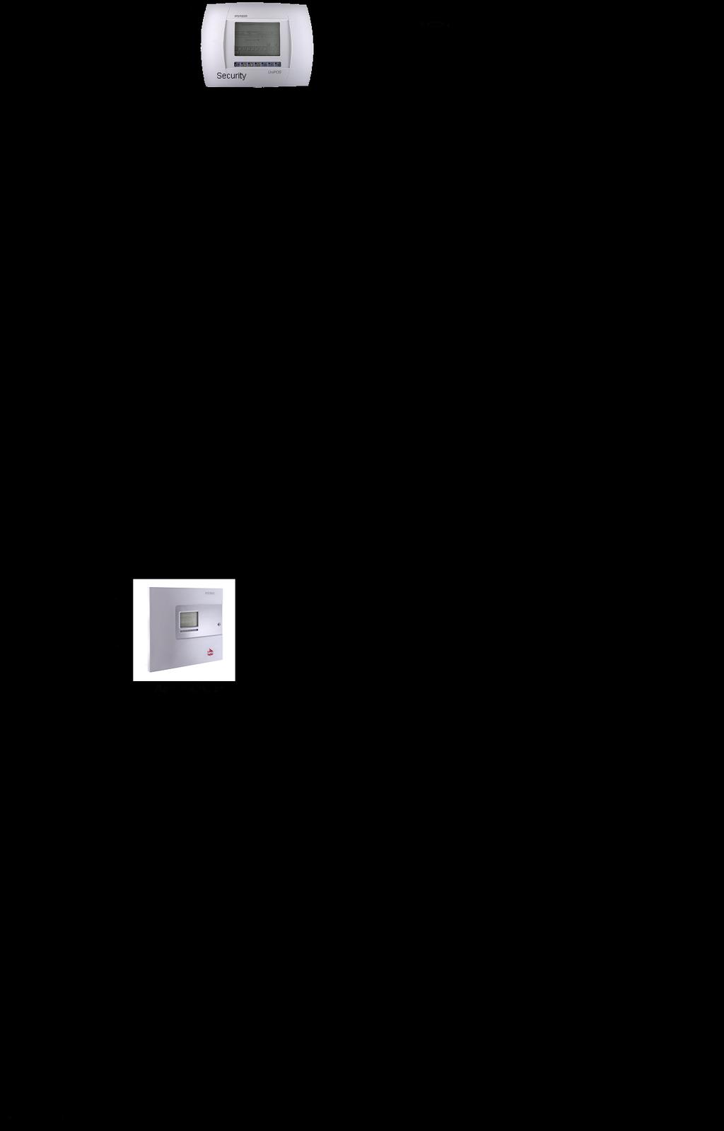

162 Instruction Manual Page 162
Interactive Fire Control Panel IFS7002 one signal loop Instruction Manual
 Interactive Fire Control Panel IFS7002 one signal loop Instruction Manual Revision 4/01.17 Contents 1. Introduction... 6 2. Terminology... 6 3. Function... 8 4. Technical data... 8 4.1. Physical configuration...
Fire Control Panel FS5100
 Fire Control Panel FS5100 INSTRUCTION MANUAL Revision 6/02.11 Contents 1. Introduction... 5 2. Terminology... 5 3. Function... 7 4. Technical data... 7 4.1. Modules... 7 4.1.1. Type of modules... 7 4.1.2.
Fire Extinguishing Control Panel INSTRUCTION MANUAL. Revision 8/ Instruction Manual Page 1 Revision 8/01.17 of 63
 Fire Extinguishing Control Panel FS5200Е INSTRUCTION MANUAL Revision 8/01.17 Instruction Manual Page 1 1. 2. 3. 4. 4.1. 4.2. 4.2.1. 4.2.2. 4.2.3. 4.2.4. 4.2.5. 4.2.6. 4.2.7. 4.2.8. 4.2.9. 4.2.10. 4.2.11.
REPEATER FS5200R INSTRUCTION MANUAL
 REPEATER FS5200R INSTRUCTION MANUAL Instruction Manual Page1 CONTENTS 1. Introduction... 3 2. Function... 3 3. Technical data... 3 4. Contents of delivery... 4 5. General information... 5 6. Duty Mode...
Fire Control Panel FS4000
 Fire Control Panel FS4000 INSTRUCTION MANUAL Revision 4/02.11 Contents 1. Introduction... 4 2. Terminology... 4 3. Function... 5 4. Technical features... 5 4.1 Fire alarm lines... 5 4.2. Current thresholds
CONVENTIONAL FIRE CONTROL PANELS FS 5100 and FS 5200
 CONVENTIONAL FIRE CONTROL PANELS FS 500 and FS 500 BASIC FEATURES Fire Control Panels FS 500 and FS 500 are up-to-date, highly reliable, multifunctional and versatile units, providing the user with unexpected
UniPOS Wireless Fire Alarm Control Panel VIT 01 WIRELESS FIRE ALARM CONTROL PANEL VIT01 INSTRUCTION MANUAL
 WIRELESS FIRE ALARM CONTROL PANEL VIT01 INSTRUCTION MANUAL Revision 8/10.13 Instruction manual Page 1 1. 2. 3. 4. 4.1. 4.2. 4.3. 4.4. 5. 5.1. 5.2. 5.3. 6. 6.1. 6.2. 6.3. 7. 7.1 7.2. 7.3. 8. 8.1. 8.2. 8.3.
Fire Control Panel FS4000
 Fire Control Panel FS4000 INSTRUCTION MANUAL Revision 11/01.17 Contents 1. Introduction... 3 2. Terminology... 3 3. Function... 4 4. Technical features... 4 4.1 Fire alarm lines... 4 4.2. Current thresholds
REPEATER FS5200R OPERATION MANUAL
 REPEATER FS5200R OPERATION MANUAL 1. Function Repeater FS5200R receives and transmits data for Fire condition and Fault condition from remote fire control panels (repeaters) and provides information about
Configuration and Operation Manual for the Unipos
 AxxonSoft Configuration and Operation Manual for the Unipos Integration Module Version 1.1 Moscow 2010 Contents CONTENTS... 2 1 LIST OF TERMS... 4 2 INTRODUCTION... 6 2.1 Document purpose... 6 2.2 Purpose
Extension Module. Fig.1
 Extension Module Type FD 4201 05/12.17 General Description Module FD 4201 is optional for the fire control panel FS4000. Expands the functionality of the fire control panel, as follow: - Connection of
Server Zones Setup in IFS IFS Panel Summary IFS loops panel specification:
 Server Zones Setup in IFS7002-4 1. IFS7002-4 Panel Summary IFS7002-4 loops panel specification: 2 panels - IFS7002-2 loops communicating through CAN interface. Built-in default CAN parameters for correct
ZX1e ZX2e ZX5e. Document No Issue 01 user manual
 ZX1e ZX2e ZX5e Document No. 996-130 Issue 01 user manual MORLEY-IAS ZX2E/ZX5E Fire Alarm Control Panels Table of Contents 1 INTRODUCTION... 4 1.1 NOTICE... 4 1.2 WARNINGS AND CAUTIONS... 4 1.3 NATIONAL
ZSC100 Gas Detection and Alarm System Controller
 ZSC100 Gas Detection and Alarm System Controller User Guide 1- Introduction... 3 1.1- General description... 3 1.2- Cautions and warnings... 3 2- Control panel... 4 2.1 Control panel overview... 4 2.2
Halton SAFE / 7.14 user guide and installation instructions
 Halton SAFE / 7.14 user guide and installation instructions VERIFIED SOLUTIONS BY H A LTO N Enabling Wellbeing Table of contents 1 System description 3 2 User Accounts 4 3 Main menu 7 3.1 Main menu - Change
U ser's Guide PC6010
 User's Guide PC6010 Quick Reference Guide This manual is for Basic and Advanced users. Each of these types of user can access a different set of functions. The and symbols next to the title of each procedure
6100 SINGLE LOOP DIGITAL ADDRESSABLE FIRE ALARM CONTROL PANEL
 6100 SINGLE LOOP DIGITAL ADDRESSABLE FIRE ALARM CONTROL PANEL USER MANUAL Protec Fire Detection plc, Protec House, Churchill Way, Nelson, Lancashire, BB9 6RT. Telephone: +44 (0) 1282 717171 Fax: +44 (0)
QA16 Addressable System
 QA16 Addressable System Operating Manual HORING LIH INDUSTRIAL CO., LTD. www.horinglih.com QA16 System Characteristics Each loop can connect with 250 devices. Easy system programming through PC to panel.
S2000-ASPT. Fire Alarm and Extinguishing Control Panel. Engineer s and User s Manual
 S2000-ASPT Fire Alarm and Extinguishing Control Panel Engineer s and User s Manual FIRE ALARM AND EXTINGUISHING CONTROL PANEL ATTENTION! To modify the panel configuration parameters use the program UProg.exe
Operation Manual Fighter ProVision Software. Version: 0.0 Revision: 1
 Operation Manual Fighter ProVision Software Version: 0.0 Revision: 1 TABLE OF CONTENTS 1. Introduction 5 2. Software Installation 5 3. PC Users 6 3.1 Introduction 6 3.2 Default Code 6 3.3 Edit PC User
SIMPLICITY CO CARBON MONOXIDE DETECTION & VENTILATION PANEL
 SIMPLICITY CO CARBON MONOXIDE DETECTION & VENTILATION PANEL USER MANUAL 1 Table of Contents 1 SAFETY INFORMATION...3 1.1 SAFETY PRECAUTIONS DURING NORMAL OPERATION OF PANEL...3 1.3 BATTERY INFORMATION...3
CSP-204 CSP-208 CSP-104 CSP-108
 Fire Alarm Control Panel CSP-204 CSP-208 CSP-104 CSP-108 Operation manual Firmware version 1.1 csp-x_o_en 06/15 SATEL sp. z o.o. ul. Budowlanych 66 80-298 Gdańsk POLAND tel. 58 320 94 00 www.satel.eu CONTENTS
Ref. 1067/024 Ref. 1067/032A Ref. 1067/052A
 DS1067-062C Mod. 1067 LBT20063 REMOTE CONTROLLABLE ALARM CONTROL PANELS Ref. 1067/024 Ref. 1067/032A Ref. 1067/052A USER MANUAL TABLE OF CONTENTS INTRODUCTION... 6 1 CONTROL DEVICES... 7 1.1 1067/022 keypad
Elite 16D Version 16 Zone Controller Arrowhead Alarm Products Ltd. Operating Guide. Proudly Designed and Manufactured in New Zealand
 6 Elite 16D Version 16 Zone Controller Arrowhead Alarm Products Ltd Operating Guide 1 Proudly Designed and Manufactured in New Zealand CONTENTS Page No. INTRODUCTION 3 About your Alarm 3 OPERATING YOUR
SCAN200E USER S MANUAL
 SCAN200E USER S MANUAL Code No. 2071 1052 rev. 1.4 Code No. 2071 1052 Rev. 1.4 Page 2/16 SCAN200E User s Manual Foreword This manual is for SCAN200E Controller running software version 2.03 or later. We
CONTENTS Installation Precautions... 1 Chapter 1 Product Introduction... 2 Chapter 2 Technical Specifications... 3
 CONTENTS Installation Precautions... 1 Chapter 1 Product Introduction... 2 Chapter 2 Technical Specifications... 3 2.1 Electrical Specifications... 3 2.2 Communication Loop Parameters... 3 2.3 Dimensions...
Installation, Operating and Maintenance Manual
 STATUS ZONES CONTROLS FIRE FAULT DISABLED FIRE 1 2 3 4 5 6 7 8 TEST FAULT DISABLED 1 5 BUZZER SILENCE RESET 1 2 TEST 2 6 LAMP TEST 3 SUPPLY 3 7 SYSTEM FAULT 4 8 SOUNDERS ACTIVATE/ SILENCE 4 FAULTS INSTRUCTIONS
2200 and 2200L ALARM CONTROL SYSTEMS
 2200 and 2200L ALARM CONTROL SYSTEMS OPERATING INSTRUCTIONS MODELS: 2200 (fitted software 3.4 or later) 2200L (fitted software 3.9L or later) Castle Care-Tech Ltd. 2200/2200L Alarm System Operating Manual
Syncro AS. Analogue Addressable Fire Control Panel. User Manual
 Syncro AS Analogue Addressable Fire Control Panel User Manual Man-1100 Issue 02 Nov. 2008 Index Section Page 1. Introduction...3 2. Safety...3 3. Panel Controls...4 3.1 Access Level 1...4 3.2 Access Level
D8024, D9024, D10024 Analog Fire Alarm Control Panels Programming Guide
 System Reset Trou ble Silence Ala rm Silence Manual Ala rm ENTER NO YES Letters Numb ers Keyword Radionics System Reset Trouble Silence Alarm Silence Manual Alarm ENTER NO YES Le ters Numbers Keyw ord
ViewMatrix. Software for Online Monitoring & Control of Matrix2000 Conventional Fire Alarm Panels. Version: 2.0 Revision: 0.1
 ViewMatrix Software for Online Monitoring & Control of Matrix2000 Conventional Fire Alarm Panels Version: 2.0 Revision: 0.1 CONTENTS 1. Introduction...3 2. Keyboard...5 2.1 POWER indication - Normal Operation...5
DYGIZONE GJD910 Lighting Controller & Enunciator
 DYGIZONE GJD910 Lighting Controller & Enunciator MASTER WIRING IDENTIFICATION Power up to the DygiZone and you will see: All the LED s (red,yellow,green and blue buttons) will flash All the LCD icons will
AFP-300/400 OPERATORS MANUAL INTELLIGENT FIRE DETECTION AND ALARM SYSTEM SOFTWARE VERSION 2.2 REVISION AUS 3
 OPERATORS MANUAL AFP-300/400 INTELLIGENT FIRE DETECTION AND ALARM SYSTEM SOFTWARE VERSION 2.2 REVISION AUS 3 NSW (Head Office) 7 Columbia Court Norwest Business Park Baulkham Hills NSW 2153 Ph: (02) 9899-4155
Operating instructions SENTRI4 Control panel based Fire detection and alarm system
 1 2 3 4 5 6 7 8 9 10 11 12 13 14 15 16 17 18 19 20 21 22 23 24 25 26 27 28 29 30 30 32 Zones Healthy 15:45 Fault Power Fault System Fault SenTRI 4 Fire System Designed to EN54 Pt 2 & 4 Operating instructions
Watchguard WGAP864 User Manual
 Watchguard WGAP864 User Manual v1.0 Issued September 2016 1 2 Table of Contents Glossary... 5 1. Introduction to your Watchguard WGAP864... 6 2. Before Operating your Alarm System... 6 3. Understanding
user manual Document No , Revision 03 November 2015
 user manual Document No. 996-202-600-3, Revision 03 November 2015 Contents 1 Introduction...1 1.1 Notice...1 1.2 Models...1 2 User Control Levels...2 2.1 Level Definition...2 2.2 User Passwords...2 3 Controls
Fire detection and alarm system Operating instructions
 Fire detection and alarm system Operating instructions Operating instructions Table of Contents User responsibility - - - - - - - - - - - - 4 Daily - - - - - - - - - - - - - - - - - - - 4 Weekly - - -
PNC 1000 SERIES 2, 4, 8 Zone Fire Alarm Control Panel
 PNC 1000 SERIES 2, 4, 8 Zone Fire Alarm Control Panel INSTALLATION, OPERATION AND MAINTENANCE MANUAL Version: CN-PM-1000.VER1.1-12/2012 EN54 INFORMATION In accordance with EN 54-2 clause 13.7, the maximum
3500 CONVENTIONAL FIRE ALARM CONTROL PANEL
 3500 CONVENTIONAL FIRE ALARM CONTROL PANEL USER MANUAL Protec Fire Detection PLC, Protec House, Churchill Way, Nelson, Lancashire, BB9 6RT. Telephone: +44 (0) 1282 717171 Fax: +44 (0) 1282 717273 Web:
Product Data Sheet. Remote Terminals. Features:
 Remote Terminals Product Data Sheet Features: Based around two core products, the Mx- 4010 Remote Display Terminal (RDT) and the fully functional Mx-4020 Remote Control Terminal (RCT). Both remote terminals
Owner s Manual. Part Number 33CS250-RC
 CONTENTS Page GENERAL... 1 CONFIGURATION... 1-4 Transmitter Display... 1 Transmitter Indicator... 1 Transmitter Front Panel Buttons... 1 Set Clock... 2 Programming Thermostat Schedules... 3 OPERATION...5
The Challenger Version 8 User Guide
 The Challenger Version 8 User Guide CONTENTS Function included in your system Introduction...4 Glossary... 6 The Challenger Console.. Liquid Crystal Display... 9 Keypad...10 Indicator Lights...11 User
Elite 64 Version 64 Zone Controller Arrowhead Alarm Products Ltd. Operating Guide. Proudly Designed and Manufactured in New Zealand
 2 Elite 64 Version 64 Zone Controller Arrowhead Alarm Products Ltd Operating Guide Proudly Designed and Manufactured in New Zealand 1 CONTENTS Page No. INTRODUCTION 3 About your Alarm 3 OPERATING YOUR
ADVISOR CD User Manual. Software from version: V
 ADVISOR CD 3403 User Manual Software from version: V6.0 142715999-1 COPYRIGHT SLC BV 1996. All rights reserved. No part of this publication may be reproduced, transmitted, stored in a retrieval system,
Building Technologies. FDUL221 en Line tester operating instructions for electricians
 FDUL221 en Line tester operating instructions for electricians 1. Intended use The FDUL221 line tester is used to diagnose an addressed detector line in FDnet/C-NET. During diagnosis, the detector line
1. User features of the GSM dialer
 1. User features of the GSM dialer The JA60GSM dialer offers many useful features described in detail below. The installer should properly demonstrate the use of the system to the user after installation
Algo-Tec 6500/6600 INTERACTIVE ADDRESSABLE FIRE CONTROL SYSTEM
 Algo-Tec 6500/6600 INTERACTIVE ADDRESSABLE FIRE CONTROL SYSTEM (1-4 LOOPS) USER MANUAL Protec Fire Detection plc, Protec House, Churchill Way, Nelson, Lancashire, BB9 6RT, ENGLAND +44 (0) 1282 717171 www.protec.co.uk
Intelligent Security & Fire Ltd
 Product Data Sheet Mx-4000 Series User Manual MX-4100, MX-4200, MX-4400, Mx-4400/LE & Mx-4800 Fire Alarm Control Panels The operation and functions described in the manual are available from Software Versions
Intelligent Security & Fire Ltd
 full installation, commissioning and operating manuals can be downloaded from www.haes-systems.co.uk combined addressable / conventional fire alarm control panel User Guide Approved Document No. MFBU-04
intelligent fire alarm ID60series panels
 intelligent fire alarm ID60series panels features LPCB approved to EN54 Parts 2 and 4 One loop capacity (99 sensors and 99 modules) 16 fire zones, 16 non fire zones Supports advanced detection such as
Laptop / PC Programming Manual
 Laptop / PC Programming Manual Doc. # Fire PC Program rev B 01.07 This Document is property of Evax Systems, Inc. The Evax Fire Solutions Programmer Components 2 1.0 System Setup 4 1.1 Interface Setup
System 800 Addressable Fire Detection & Alarm System
 SECTION 5: page 1 Section 5: System 800 Addressable Fire Detection & Alarm System SECTION 5: page 3 10 reasons to specify 800 1 Plug and Play A user friendly panel not requiring special software tools
ANALOGUE ADDRESSABLE FIRE PANEL
 ANALOGUE ADDRESSABLE FIRE PANEL INSTALLATION AND PROGRAMMING MANUAL Contents 1. Introduction... 5 1.1 General Description... 5 1.2 General Specifications... 5 1.2.1 General Technical Specifications...6
User Manual. Dryer Controller M720
 User Manual Dryer Controller M720 Hardware version 1.00 Software version 1.00 Preliminary version Manual M720 Dryer controller Page 1 of 42 Document history Preliminary version: - Created in April, 2009
BS-316. Gas detection control panel up to 16 inputs. Installation operation manual
 BS-316 Gas detection control panel up to 16 inputs Installation operation manual Page 1 from 21 Contents 1 Operation instructions--------------------------------------------------------------------------------------------------------------------3
Instructions manual. By-alarm. By-alarm Manager software
 Instructions manual By-alarm By-alarm Manager software Index 1. Procedure for the complete programming of the By-alarm system 5 Operations to be carried out prior to the programming with By-Alarm Manager
Operating instructions Vigilon panel and Network node Fire detection and alarm system
 Healthy 15:45 Fault Power Fault Vigilon Fire System GENT 2015 Designed to EN54 Pt 2 & 4 System Fault Operating instructions Vigilon panel and Network node Fire detection and alarm system Test Fire Fault/Dis
Ref. 1067/024 Ref. 1067/032A Ref. 1067/052A
 DS1067-064D Mod. 1067 LBT20065 REMOTE CONTROLLABLE ALARM CONTROL PANELS Ref. 1067/024 Ref. 1067/032A Ref. 1067/052A PROGRAMMING MANUAL TABLE OF CONTENTS INTRODUCTION... 7 1 CONTROL DEVICES... 8 1.1 1067/022
SCAN20 Series Gas Detection Controller
 SCAN20 Series Gas Detection Controller USER S MANUAL Code Number 2071 1022 SCAN20 USER S MANUAL Code no. 2071 1022 Page 1/14 Foreword This manual is made for SCAN20 Controllers equipped with the software
Power Wave LCD Keypads. Users Operating and Programming Guide Version 2.00
 Power Wave LCD Keypads CR-16S CR-16M Users Operating and Programming Guide Version 2.00 P/N 7102265 Rev. C N.A May 2003 Contents Introduction...4 Meet the PowerWave Alarm Control System... 4 Typical Alarm
RANGER 7600 DOWNLOADABLE CONTROL COMMUNICATOR INSTALLATION MANUAL
 RANGER 7600 DOWNLOADABLE CONTROL COMMUNICATOR INSTALLATION MANUAL TABLE OF CONTENTS 1. TABLE OF CONTENTS... P.1 2. GENERAL DESCRIPTION... P.2... 3. STANDARD AND OPTIONAL PARTS LIST... P.2... 4. FEATURE
Modular Standard HP Chiller 1/4 screw compressor with Carel driver
 Program for pco¹ pco 2 and pcoc Modular Standard HP Chiller 1/4 screw compressor with Carel driver Manual version 1.0 25 September 2003 Program code: FLSTDmMSDE Do we want you to save you time and money?
"DMTeh" Ltd. Pleven. Fire conventional panel FP 9000 Installation, setup and operation.
 ISO 9001:2008 Certified Company Tel./Fax : +359 64 801 597 e-mail : office@dm-teh.com web : www.dm-teh.com Address : Pleven,Bulgaria 5800 34 Gen. Lt. Atanas Stefanov Str. "DMTeh" Ltd. Pleven Fire conventional
OWNER S MANUAL. Part Number P RF
 OWNER S MANUAL CPE230RF Commercial Programmable Thermostat Wireless Transmitter Part Number P474-2300RF CONTENTS Page GENERAL... 2 CONFIGURATION... 3-12 Transmitter Display... 3 Transmitter Indicator...
Ref.1067/032 Ref.1067/042
 DS1067-033A Mod. 1067 LBT8631 BUS CONTROL PANEL 8/32 INPUTS Ref.1067/032 Ref.1067/042 USER MANUAL TABLE OF CONTENTS 1 PREFACE... 5 2 COMMAND DEVICES... 6 2.1 1067/021 DISPLAY KEYPAD... 6 2.2 ELECTRONIC
with internal sensor (channel 1) with an external sensor (channel 2) A-Editor software, Professional AK20 version (not for version AK4)
 with an external sensor (channel 2) A-Editor software, Professional AK20 version (not for version AK4)") Examples of use Example Creating an SMS-based alarm with confirmation A project file must first be created using the A-Editor software. This project file is then stored in the alarm modem. The alarm modem
Examples of use Example Creating an SMS-based alarm with confirmation A project file must first be created using the A-Editor software. This project file is then stored in the alarm modem. The alarm modem
HERCULES 6 GRAPHICS SYSTEM
 HERCULES 6 GRAPHICS SYSTEM USER MANUAL Protec Fire Detection PLC, Protec House, Churchill Way, Nelson, Lancashire, BB9 6RT. Telephone: +44 (0) 1282 717171 Fax: +44 (0) 1282 717273 Web: www.protec.co.uk
IDS S E C U R I T Y IDS816. User Manual. MANUAL NO A ISSUED November 2004 VERSION 1.00
 INHEP DIGITAL IDS S E C U R I T Y IDS816 User Manual MANUAL NO. 700-283-02A ISSUED November 2004 VERSION 1.00 Contents 1. Introduction to the IDS816... 4 2. Understanding the Keypad Indicators... 4 3.
Other trade names mentioned in this document may be registered trademarks or trademarks of respective product manufacturers or vendor products.
 Attention! Read this user manual carefully. Representative of the company installing the alarm system will explain which security module SP231 functions needs to be activated to ensure proper security
Discovery 4 Loop Analogue Addressable Control Panel (NVI & NVA series Protocols)
") Nitin Ventures FZE. (A Division of Nitin Fire Protection Industries Ltd.) BETTER TO BE SAFE Discovery Analogue Addressable Fire Alarm Panels Discovery 4 Loop Analogue Addressable Control Panel (NVI & NVA
Nitin Ventures FZE. (A Division of Nitin Fire Protection Industries Ltd.) BETTER TO BE SAFE Discovery Analogue Addressable Fire Alarm Panels Discovery 4 Loop Analogue Addressable Control Panel (NVI & NVA
The EN54 Part 2 & 4 Fire System
 Scope of work: To design, supply, install and commission an Analogue Addressable Fire Alarm Control System in accordance with the details specified herein and in accordance with supplied drawings The EN54
Dryer Controller M720
 User Manual Dryer Controller M720 Hardware version 2.00 Software version 2.00 Manual M720 Dryer controller Page 1 of 60 Document history Preliminary version: - Created in April, 2009 Hardware Version 2.00,
ANALOGUE ADDRESSABLE FIRE PANEL MAGPRO96 INSTALLATION AND PROGRAMMING MANUAL
 ANALOGUE ADDRESSABLE FIRE PANEL MAGPRO96 INSTALLATION AND PROGRAMMING MANUAL C 1293 Contents 1. INTRODUCTION...4 1.1 General Description... 4 1.2 General Specifications... 4 1.2.1 General Technical Specifications...
EasyLoader. End User Manual
 EasyLoader End User Manual Table of Contents Table of Contents... 1 System Configuration... 3 Introduction... 4 SAFETY AND MAINTENANCE INSTRUCTIONS... 4 GLOSSARY... 4 Basic Operations... 8 ARMING YOUR
Contents. Glossary
 Contents Glossary ------------------------------------------------------------------------------------------------------ 6 1. Introduction to the IDS 1632 -------------------------------------------------------------
HARDWIRED CONTROL PANELS
 USER GUIDE 9651 HARDWIRED CONTROL PANELS Contents 1. Introduction...3 The Alarm System...3 The Keypad...3 About This Guide...5 2. Everyday Operation...6 How Do I Know if the System is Working?...6 Setting
TS5160. Installation & User Guide. Compatible Equipment. CPA6 0M - Output Module Loudspeaker DC54/58 - Digital Communicators (Stand Alone Only)
") Installation & User Guide Compatible Equipment CPA6 0M - Output Module 9040 - Loudspeaker DC54/58 - Digital Communicators (Stand Alone Only) 496527 Issue A 1 of 16 TS5160 Overview Introduction Specification
Installation & User Guide Compatible Equipment CPA6 0M - Output Module 9040 - Loudspeaker DC54/58 - Digital Communicators (Stand Alone Only) 496527 Issue A 1 of 16 TS5160 Overview Introduction Specification
SOLO Single Loop Addressable Fire Control Panel
 Solo Single Loop Analogue Addressable Fire Control Panel Apollo Protocol Installation, Commissioning & Operating Manual Issue 03 June 1999 CONTENTS Section... Page 1. Introduction...1 2. Safety...2 3.
Zerio Plus EDA-D6000 Radio Combined Heat Detector and Sounder Installation Instructions
 Zerio Plus EDA-D6000 Radio Combined Heat Detector and Sounder Installation Instructions EN54-3:2001+A1:2002+A2:2006 EN54-5:2000+A1:2002 EN54-25:2008 0359 Electro Detectors Ltd. Electro House Edinburgh
16 and 16 plus User s Guide
 16 and 16 plus User s Guide GALAXY 16+ V2.XX 06.22 TUE 30 JUN 1 2 3 4 5 6 7 8 9 * 0 # A u B u ent esc Contents INTRODUCTION... v QUICK OPERATION GUIDE...vii GLOSSARY OF TERMS... ix KEYPAD INFORMATION...
Control/Communicator Installation Manual
 DAS NETWORX NX-12 Control/Communicator Installation Manual General Description...2 Ordering Information...2 Option Definitions...3 Programming the LED Code Pads...5 Programming the NX-12...9 Types of Programming
2000 SERIES DIAGNOSTIC ALARM CONTROL SYSTEM
 2000 SERIES DIAGNOSTIC ALARM CONTROL SYSTEM OPERATING INSTRUCTIONS MODELS: 2300 2500 2700 This information is relevant to systems fitted with Issue 4.1 (or later) Master Keypad Software, also to Networked
ID2000. operating manual
 ID2000 operating manual 997-434-000-2, Issue 2 Contents ID2000 Series Operating Manual Contents 1 Introduction 1 1.1 Associated Documents 1 1.2 The ID2000 Panels 1 1.3 Cleaning 2 2 Panel Controls and Indicators
ID50series. intelligent fire alarm panels
 ID50series intelligent fire alarm panels features LPCB approved to EN54 parts 2 and 4 One loop capacity (99 sensors and 99 modules) 16 fire zones, 16 non fire zones Supports NOTIFIER advanced range of
Control Panel User Guide
 Fire Detection & Alarm System Control Panel V4.14 Control Panel User Guide (TO BE RETAINED BY USER) 26-0397 Issue 6 Fike s policy is one of continual improvement and the right to change a specification
AGRI-ALERT 9600 ALARM SYSTEM USER MANUAL
 AGRI-ALERT 9600 ALARM SYSTEM USER MANUAL M 890-00279 rev. 14 K 895-00004 rev. 00 Manufacturer: Viatron Electronics 5200, Armand-Frappier St-Hubert (Quebec) Canada J3Z 1G5 WARNINGS The warranty can be void
8 plus and16 plus. User s Guide * # ent. esc GALAXY 16+ V2.XX TUE 30 JUN. IU ZST 962 Issue 2. A u B u
 8 plus and16 plus User s Guide GALAXY 16+ V2.XX 06.22 TUE 30 JUN 1 2 3 4 5 6 7 8 9 0 * # A u B u ent esc IU1-0018 ZST 962 Issue 2 Contents INTRODUCTION... 1 Glossary of Terms... 3 KEYPAD INFORMATION...
Owner s Manual. Part Number 33CS250-FS and 33CS220-FS
 Debonair 33CS Flush-Mounted Flatstat Commercial Programmable Thermostat IMPORTANT: Read entire instructions before programming the thermostat. Owner s Manual Part Number 33CS250-FS and 33CS220-FS GENERAL
BENTEL SECURITY declines all responsibility in the event of unauthorized intervention on the FireClass200 control panel.
 V4.2 BUI 0.1 061099 The FireClass200 is available in the following models: FC200 - Master panel with 4 A Linear power supply; FC200/S - Master panel with 2.5 A Switching power supply; FC200/SL - Slave
QUICK USER GUIDE. Alarm Control Panel
 Alarm Control Panel Firmware version 2.10 QUICK USER GUIDE The full version of User Manual and other manuals are available on CD included in the control panel delivery set or on the website www.satel.eu
ZP2 Series Operation Manual
 ZP2 Series Operation Manual P/N 501-405203-2-31 REV 03.10 ISS 07NOV13 Copyright Trademarks and patents Manufacturer Version Certification European Union directives Contact information 2013 UTC Fire & Security.
INDEX 1- Introduction The Control Pane...7l 4.1- The Control Panel 1 and 2 Loops The Control Panel 4 and 8 Loops...
 GUIDE MANUAL INDEX 1- Introduction...5...5...6 4- The Control Pane...7l 4.1- The Control Panel 1 and 2 Loops...7 4.2- The Control Panel 4 and 8 Loops...9 5- Installation Guide...10 5.1- Pre-Installation
Challenger10 Users Manual
 Challenger10 Users Manual P/N MAUSER-TS1016 REV 01 ISS 18FEB13 Copyright Trademarks and patents Manufacturer Agency compliance Contact information 2013 UTC Fire & Security. All rights reserved. The Challenger
Analogue Addressable Fire Panels FP1500. Manual for Installation, Configuration and Commissioning
 Analogue Addressable Fire Panels FP1500 Manual for Installation, Configuration and Commissioning Version 2.1 / November 2003 Aritech is a GE Interlogix brand. http://www.geindustrial.com/ge-interlogix/emea
Gas Detection System TOX ALARM DG2000-Garage
 Gas Detection System TOX ALARM DG2000-Garage Gas Detection System 32 independent programmable channels 2 programmable alarm levels for each gas = up to 6 for each channel LCD alphanumeric display of gas
The complete R&TTE Declaration of Conformity for each Panel can be found at
 USER GUIDE FC200 - FC200/S - FC200/SL - FC100: Hereby, Bentel Security, declares the above mentioned Control Panels to be in compliance with the essential requirements and other relevant provisions of
Summary of Keypad Main User Commands
 User Manual Summary of Keypad Main User Commands Full Set Code > Part Set Code > System Unset Silence an Alarm Partition Full Set Partition Part Set Code> Code> Code > > Partition No. > Code > > Partition
1 measurement signal input 4-20 ma for connection to an external gas sensor 5 freely programmable alarm switching points per measuring point
 Medium - Control - System Franke & Haqenest GmbH Borngasse 1a * 04600 Altenburg Tel: 03447-499 313-0 Fax: 03447-499 313-6 email: info@mcs-gaswarnanlagen.de MCS User Guide MCS GasController Microprocessor
SI120 Guarto Easy I. Alarm system. Fire & Security Products
 Alarm system SI120 Guarto Easy I Central alarm control unit with integrated communicator Simple to program Simple and reliable to operate Flexible Extensive communications Simple to install Alarm receiving
IDS S E C U R I T Y IDS816. User Manual MANUAL NO C ISSUED APRIL 2005 VERSION 2.00
 INHEP DIGITAL IDS S E C U R I T Y IDS816 User Manual MANUAL NO. 700-283-01C ISSUED APRIL 2005 VERSION 2.00 Contents 1. Introduction to the IDS816... 4 2. Understanding the Keypad Indicators... 4 3. Programmable