Alarm Gateway Object for Wonderware Application Server User Guide Ver 1.x Rev 1.11 PR 00185
|
|
|
- Bridget Montgomery
- 5 years ago
- Views:
Transcription
1 Alarm Gateway Object for Wonderware Application Server User Guide Ver 1.x Rev 1.11 PR WONDERWARE FINLAND P.O. Box 38 FIN Helsinki Finland tel. int fax int
2 i Table of Contents Introduction... 1 Installing the Alarm Gateway Object... 3 Hardware requirements... 3 Software requirements... 3 Content of delivery package... 3 Installing standalone object... 4 Object import... 4 Object configuration... 5 Licensing requirements Demo License installation Software key installation Configuration General Configuration Consumer: Provider: Run-Time Object Attributes Custom Alarm/Event attributes Wonderware alarm system custom attributes Troubleshooting Wonderware alarm system custom attributes Exposed Alarm Fields Configuration attributes Exposed attributes Custom Acked alarm comment field Overview Configuration UReason gateway Alarm Gateway UReason Mimic functionality Mimic functionally without UReason alarming system Multiple distributed Alarm Gateway configuration setup sample Object configuration Alarm client configuration Redundant Alarm Gateway configuration setup sample Troubleshooting Advanced Troubleshooting Object upgrade procedure Object clean uninstall procedure... 69
 and/or other Alarm Providers compatible with Wonderware Alarm System: Alarm")
3 1 Alarm Gateway Object for Wonderware Application Server Introduction The Alarm Gateway Object (Alarm Gateway) is a basic component of Wonderware Finland Alarm Extension Pack and provides the functionality to create separate configurable Alarm Provider for alarms coming from Wonderware Application Server (WAS) and/or other Alarm Providers compatible with Wonderware Alarm System: Alarm Gateway supports advanced alarm filtering, mimic and shelved alarms, possibilities to use and modify the user defined fields and event priority fields. Avoids alarm loss and duplicated alarms in high loaded systems. Supports functionality to send/receive alarms to/from Wonderware alarming system from/to UReason Alarm Management system. The Alarm Gateway Object is developed by using Wonderware Distributed Alarm Toolkit. The Alarm Gateway can be used to solve, for example, the following tasks: Avoid alarm loss in high loaded systems: WAS Historical alarms and events are stored in a circular buffer, where the oldest entries are discarded to make room for new ones, so in case there generated a lot of events then important alarms can be lost. By using the Alarm Gateway, it is possible to store all important alarms in separate Alarm Gateway buffer - that can be done by querying alarms/events only with priorities from 1 to 998:
4 2 Note: Alarm Gateway alarm buffer can contain about alarms. The total number of stored alarms depends on size of alarms. Change the event priority: WAS alarming system does not provide possibility to configure event priority - all events have built-in priority 999. By using Alarm Gateway, it is possible to change the event priority by using the setpriority custom attribute.for more information see the Custom attributes section setpriority later in this User Guide. Connect to UReason alarming system: Alarm Gateway can send alarms/events from Wonderware alarming system to UReason alarming system. For more information see UReason gateway section later in this User Guide. Wonderware alarm providers (WAS, InTouch) Alarm Gateway UReason alarming system
5 3 Installing the Alarm Gateway Object Hardware requirements The Alarm Gateway Object has the same hardware requirements as Wonderware Application Server. It is strongly recommended to have computer at least with 2 GHz or faster processor, 64-bit. A multi-core processor is also strongly recommended. The Intel Itanium 2 processor is not supported. Software requirements The Wonderware Application Server 3.1 version or later is supported. Content of delivery package The Alarm Gateway Object can be delivered: 1) included in Wonderware Finland Alarm Extension Pack or 2) as a separate package. The following are Alarm Gateway Object files: AlarmGateway34.aaPDF - Alarm Gateway Object standard description file containing the implementation code for a base template AlarmGateway.aaDEF - Alarm Gateway Object definition file.pdf Alarm Gateway Object User Manual (this document)


6 4 Installing standalone object Object import 1) Copy Alarm Gateway object to some folder, e.g. to C:/Install. 2. Start the ArchestrA IDE and import the AlarmGateway34.aaPDF file to a new/existing galaxy (in the further explanation we will assume that a new galaxy grtest1 is used). Note: If you are using existing galaxy and there are already deployed an older Alarm Gateway object version please, following upgrade instruction from section Object upgrade procedure. 3) After importing $AlarmGateway template is added to Template Toolbox:
 Create AppEngine and assign it to Platform object (Deployment View) Note: Highly recommended is to deploy object Alarm Gateway to separate engine where are no production objects deployed, to")
7 5 Object configuration 1) Create WinPlatform object (if is not existing already) with alarm provider feature enabled. 2) Create AppEngine and assign it to Platform object (Deployment View) Note: Highly recommended is to deploy object Alarm Gateway to separate engine where are no production objects deployed, to distribute possible CPU load among multiple CPU cores. Engine scan period is recommended to set at least 1 second and more (2-3 seconds) if object is planned to be used in high load alarm systems (more than 50 active alarms) and with enabled additional features like Custom Alarm/Event attributes UReason alarm system.


8 6 3) Create Area object and assign in to AppEngine object

9 7 4) Create Alarm Gateway instance and assign it to Area object. 5) Open Alarm Gateway object editor and configure following parameters in: a) Tab Consumer: Set Alarm Query: \Galaxy!Area_001 Set To Priority: 1 Set From Priority: 998 Enable Filter Alarm Types: set filter Comm Where Area_001 is area name what is host of Alarm Gateway object or other area can be specified that host objects with alarming enabled. b) Tab Provider: Change alarm provider name if needed of alarm clients:

10 8 c) Tab UReason Enable connection to UReason alarming system if used:
11 9 d) Tab Log Flags If needed enable diagnostic logging, for more details see section Advanced Troubleshooting
 Deploy created all objects 8) License Alarm Gateway object - see Section Licensing requirements for details.")

12 10 6) Create or import some objects with alarming enabled under Area_001. 7) Deploy created all objects 8) License Alarm Gateway object - see Section Licensing requirements for details. 9) Create or import InTouch application to test AlarmGateway alarms configure alarm client Alarm Query: \\WWNode\AlarmGatewayProvider!Area_001 or \\ \AlarmGatewayProvider!Area_001 Note: Query without Nodename like AlarmGatewayProvider!Area_001 or /AlarmGatewayProvider!Area_001 will not work on Windows ) Run InTouch application and check alarms

13 11

14 12 Licensing requirements Alarm Gateway object support two types of licenses: The demo license is for free and provides an unlimited functionality, but it is valid only for a limited time period. The software key enables the Alarm Gateway Object unlimited full time running without any restrictions. Demo License installation The demo license is for free and provides an unlimited functionality, but it is valid only for a limited time period. After demo license expiration, the Alarm Gateway will stop to provide the alarms. The demo license can be obtained by sending inquiry to info@wonderware.fi. To activate the received demo License key, you need to set it to object License_DemoKey attribute: If demo license is valid (correct key is installed) License_IsLicensed attribute is true and in License_DemoExpirationDate attribute is displayed expiration date after that product stops working.
; - get Customer ID from object License_CustomerID attribute; - copy/paste it to e-mail")
15 13 Software key installation The software key enables the Alarm Gateway Object unlimited full time running without any restrictions. To get and enable the software key: - get Product ID from object License_ProductID attribute (e.g. PR ); - get Customer ID from object License_CustomerID attribute; - copy/paste it to (or text file or similar) and provide this Customer ID string when ordering the Alarm Gateway Object; - when product is purchased, copy the received Software Key to object License_SoftwareKey attribute: If license key is valid (correct key is installed) License_IsLicensed attribute is set to true and product is ready for use. Licensing run-time attributes: Attribute Description Run-Time Access License_CustomerID Unique generated Read-Only customer ID License_DemoExpirationDate Demo license expiration Read-Only date License_DemoKey Demo license key User License_IsLicensed If True then product is Read-Only licensed License_ProductID Product ID Read-Only License_SoftwareKey Product software key User
16 14 Configuration For general information about objects (including relationships, deployment and alarm distribution) - see the Wonderware Integrated Development Environment (IDE) documentation. For information on configuration options for object information, scripts, user-defined attributes (UDAs), or attribute extensions, click Extensions Help in the Help file header. General Configuration Use the Consumer tab to configure and tune the behavior of the Alarm Gateway Object consumer: Consumer: Editor Option Associated Attribute (s) Description Alarm Query Consumer.AlarmQuery Consumer Alarm Query From Priority Consumer.FromPriority Enter the starting value of the alarm priority range To Priority Consumer.ToPriority Enter the ending value of the alarm priority range Query Type Consumer.QueryType Alarm query type. Alarm Type filter Enable/disable: Consumer.FilterAlarmTypesEnabled Consumer.FilterAlarmTypes Provider advanced functionality to filter alarms by type e.g. can filter out all Comm alarms. Use the Provider tab to configure and tune the behavior of the Alarm Gateway Object provider: Provider:
17 15 Editor Associated Attribute Description Option Name Provider.Name Alarm provider name Alarm Historical Buffer Size Alarm Group Hierarchy XML Alarm Backup XML Location Exposed Alarm Fields arrays Size Provider.AlarmBufSize Provider.AlarmHierarch yfile Provider.AlarmBackup Location Exposed_Alarm_Fields _Arrays_Size Alarm buffer size. Path to WAS generated Alarm (Area) hierarchy file Default value: c:\program Files\ArchestrA\Framework\Bin\GlobalDataCache \AreaHierarchy.xml Alarm Backup XML files Location on disk Exposed Alarm Fields array size for more details see section Exposed Alarm Fields Custom Acked Alarm field Enable/disable: EnableCustomAckField CustomAckAlarmField For more details see section Custom Acked alarm comment field
18 16 Run-Time Object Attributes All object attributes are grouped into following groups by prefix: AlarmGateway - defines attributes for Alarm Gateway general configuration and status. Provider_ - defines attributes for Alarm Provider configuration Consumer_ - defines attributes for Alarm Consumer configuration. Licence_ - defines attributes for licensing Set - defines custom attributes see section Custom attributes for more information The following table describes the run-time only attributes for the Alarm Gateway Object. Note: Configurable run-time attributes are described in the configuration sections. For more information, see Configuration section above. Attribute Description Run-Time Access AlarmGateway_Started If true Alarm Gateway is Started Read-Only and running. AlarmGateway_LastErrorMessage Last Error Message Read-Only AlarmGateway_LastErrorCode Last Error Code (No errors = 0) Read-Only AlarmGateway_Restart Trigger if set to True then User restarts Alarm Gateway. Consumer.Status Current status of Alarm Gateway Read-Only AlarmGateway_AlarmGroups Displays all created alarm groups Read-Only Note: It is highly recommended to run any Alarm Gateway Object in separate Engine since Alarm Gateway uses scan interval for reading the alarms. Recommended Engine scan interval for Alarm Gateway is at least 1000 ms.
19 17 Custom Alarm/Event attributes By using custom attributes, it is possible to change following alarm data fields in Wonderware alarm system or in UReason alarm system: For Wonderware alarm custom attributes prefix setww_ is used for Ureason attribute prefix setur_ is used. Custom Attribute Alarming system Description SetWW_User1 Wonderware User-defined field number 1. SetWW_User2 Wonderware User-defined field number 2. SetWW_User3 Wonderware User-defined field, string. SetWW_Priority Wonderware Alarm/Event Priority. SetUR_Source UReason Alarm Source SetUR_Class UReason Alarm Class Custom attributes can be set from WAS scripts with following command: Syntax: objectname.customattribute = Alarm/Event name = value
20 18 Wonderware alarm system custom attributes SetWW_Priority Is used to set Wonderware alarm system alarm and event Priority (valid range from 1 to 999). Sample: Following command sets Wonderware alarming system alarm priority to 10 for alarm Generator_001.Analog_001.Lo: AlarmGateway_001.setWWPriority = Me.Tagname + ".Analog_001.Lo=10"; Note: value is needed to set before alarm is active.
21 19 SetWW_User1 Is used to set Wonderware alarm system User-defined (User1) float field. Sample: Following command sets Wonderware alarming system alarm User 1 field to 10.2 for alarm Generator_001.Analog_001.Lo: AlarmGateway_001.setWW_User1 = Me.Tagname + ".Analog_001.Lo=10.2"; Note: value is needed to set before alarm is active.
22 20 SetWW_User2 Is used to set Wonderware alarm system User-defined (User2) float field. Sample: Following command sets Wonderware alarming system alarm User 2 field to 23.3 for alarm Generator_001.Analog_001.Lo: AlarmGateway_001.setWW_User2 = Me.Tagname + ".Analog_001.Lo=23.3"; Note: value is needed to set before alarm is active.


23 21 SetWW_User3 Is used to set Wonderware alarm system User-defined (User3) string field. Sample: Following command sets Wonderware alarming system alarm User 3 field to Test 1 for alarm Generator_001.Analog_001.Lo: AlarmGateway_001.setWW_User3 = Me.Tagname + ".Analog_001.Lo=Test 1"; Setting value from Object Viewer: Note: value is needed to set before alarm is active.

24 22 SetWW_Operator Is used to set Wonderware alarm system User-defined (Operator) string field. Sample: Following command sets Wonderware alarming system alarm Operator field to Test 1 for alarm Generator_001.Analog_001.Lo: AlarmGateway_001.setWW_Operator = Me.Tagname + ".Analog_001.Lo=Test 1"; Note: value is needed to set before alarm is active.
25 23 SetWW_OperatorFullName Is used to set Wonderware alarm system User-defined (OperatorFullName) string field. Sample: Following command sets Wonderware alarming system alarm OperatorFullName field to Test 1 for alarm Generator_001.Analog_001.Lo: AlarmGateway_001.setWW_OperatorFullName = Me.Tagname + ".Analog_001.Lo=Test 1"; Note: value is needed to set before alarm is active.
26 24 SetWW_OperatorDomain Is used to set Wonderware alarm system User-defined (OperatorDomain) string field. Sample: Following command sets Wonderware alarming system alarm Operator Domain field to Test 1 for alarm Generator_001.Analog_001.Lo: AlarmGateway_001.setWW_ OperatorDomain = Me.Tagname + ".Analog_001.Lo=Test 1"; Note: value is needed to set before alarm is active.


27 25 Troubleshooting Wonderware alarm system custom attributes In case custom attribute is not set for alarm following steps can be performed to troubleshoot the issue. Enable general alarm flag: Set custom attribute e.g. from WAS script: After script is executed check is appropriate message (Al379) logged in logger that indicates that custom attribute is set: Rise alarm and check is Alarm name is the same as alarm name defined in set command:

28 26 Alarm Name mentioned in messages Al379 and NewAE54 must match to function work properly.

29 27 UReason alarm system custom attributes setur_source Is used to set UReason alarm system alarm Source property. Sample: Following command sets UReason alarm parameter Source to SP200 for alarm Generator_001.Analog_001.Lo: AlarmGateway_001.setURSource = Me.Tagname + ".Analog_001.Lo=SP200";

30 28 setur_class Is used to set UReason alarm system alarm Type property. Note: Class is a critical parameter for UReason alarm system, all alarms/events that are intended for use in UReason alarm system must have defined valid class. Sample: Following command sets UReason alarm Class (Type) property to THP Decrease for alarm Generator_001.Analog_001.Lo: AlarmGateway_001.setURClass = Me.Tagname + ".Analog_001.Lo=THP Decrease";

31 29 setur_priority Is used to set UReason alarm system alarm Severity property. Sample: Following command sets UReason alarm Severity property to 5 (Warning) for alarm Generator_001.Discrete_001: AlarmGateway_001.setUR_Priority = Me.Tagname + ".Discrete_001=5"; Note: UReason alarm system has following alarm/event priorities: 1 - Critical 2 High Severity 3 Medium Severity 4 - Low Severity 5 - Warning 6 Information
 value for alarm Generator_001.Analog_001.Lo: AlarmGateway_001.setUR_Source = Me.Tagname + \".Analog_001.Lo=\" + Me.")
32 30 setur_source Is used to set UReason alarm system alarm Source property. Sample: Following command sets UReason alarm Source property to Me.Tagname (Generator_001) value for alarm Generator_001.Analog_001.Lo: AlarmGateway_001.setUR_Source = Me.Tagname + ".Analog_001.Lo=" + Me.Tagname;
33 31 setur_mimicwindow Is used to set UReason alarm system alarm MimicWindow property. For details see Alarm Gateway UReason Mimic functionality section. Sample: Following command sets UReason alarm MimicWindow property: AlarmGateway_001.setUR_MimicWindow = Me.Tagname + ".Analog_001.Lo=SP200";
 In object editor open tab Provider a) Enable Exposed Alarm Fields feature.")
34 32 Exposed Alarm Fields Exposed Alarm Field arrays are used to expose specific Alarm information (fields) as object attributes that can be used in WAS scripting. Following configuration is needed to setup Exposed Alarm Fields: 1) In object editor open tab Provider a) Enable Exposed Alarm Fields feature. b) and set Exposed Alarm Fields arrays length: c) Deloy Alarm Gateway object. d) Define exposed alarm configuration XML: XML structure: Root: <AlarmConfiguration> Element: Name: Alarm Attributes: Name Alarm name alarm names are case sensitive. Note: Also wildcards are supported following samples are correct: 1) GenAlarm* Adds to exposed list all Alarms that name starts with GenAlarm:


35 33 2) *HiHi - Adds to exposed list all Alarms that name ends with HiHi all HiHi priority alarms.

36 34 3) *Value1.Lo* ID used defined ID -is used to delete entries from arrays by set value to AlarmDeleteAlarmStringID attribute. <AlarmConfiguration> <Alarm Name="Alarm_300.Value1.Lolo" ID= 10 /> <Alarm Name="Alarm1*" ID= 11 /> </AlarmConfiguration>
, Discreate_001, Discreate_002 e) set it to Alarm Gateway Big String XML.")
 When defined alarm raises g) Exposed Alarm Field arrays are filled with defined Alarm")
37 35 Note: For testing proposes in WAS following sample alarms are defined Analog_001 (LoLo,Lo,Hi,HiHi), Discreate_001, Discreate_002 e) set it to Alarm Gateway Big String XML.AlarmListConfiguration attribute. f) When defined alarm raises g) Exposed Alarm Field arrays are filled with defined Alarm Fields that are defined in XML.AlarmListConfiguration attribute:

38 36 Configuration attributes XML.AlarmListConfiguration Stores Alarm XML configuration XML sample: <AlarmConfiguration> <Alarm Name="*.HiHi" ID ="10"/> </AlarmConfiguration> Sample WAS script: AlarmGateway_001.XML.AlarmListConfiguration = "<AlarmConfiguration>" + "<Alarm Name=""*.HiHi"" ID =""10""/>"+ "</AlarmConfiguration>"; AlarmIDList datatype: int array Array size: is defined in editor Exposed_Alarm_Fields_Arrays_Size attribute. Description: Array of Alarm Gateway generated exposed alarm unique ID that can be used to identify each exposed alarm. AlarmDeleteAlarmStringID datatype: int Description: Deletes entry from Exposed Alarm Fields that matches specified alarm ID in array AlarmIDList.

 file Alarm node attribute ID")
39 37 Alarm.UserID datatype: int array Description: Displays User defined ID from Alarm list configuration (attribute XML.AlarmListConfiguration) file Alarm node attribute ID <AlarmConfiguration> <Alarm Name="*.HiHi" ID ="10"/> </AlarmConfiguration>
40 38 Exposed attributes Alarm.Name datatype: string array Description: Exposed alarm name Alarm.User1 datatype: string array Array size: is defined in editor Exposed_Alarm_Fields_Arrays_Size attribute. Description: Exposes Alarm field User1

41 39 Alarm.User2 datatype: float array Array size: is defined in editor Exposed_Alarm_Fields_Arrays_Size attribute. Description: Exposes Alarm field User2 Alarm.User3 datatype: float array Array size: is defined in editor attribute Exposed_Alarm_Fields_Arrays_Size attribute. Description: Exposes Alarm field User3

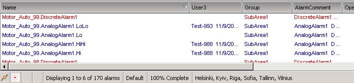
42 40 Custom Acked alarm comment field Overview Using Alarm gateway is possible to configure custom Acked alarm comment field for Acked alarms this is useful if alarm descriptions are used: Alarm description is stored in AlarmComment field: If alarm is Acked by default AlarmComment value is overwritten by alarm comment value:

43 41 With Alarm Gateway is possible to configure different Alarm field to store Ack comment and preserve Alarm description.

44 42 Configuration Editor Custom alarm Ack comment field feature can be configured in tab Provider section Custom Acked Alarm Field:

45 43 Runtime Custom alarm Acked comment field is possible to configure in runtime without Alarm gateway restart:

46 44 Attributes EnableCustomAckField Datatype: bool Description: enables/disables Custom alarm Ack comment field feature. If true - Custom alarm Ack comment field feature is enabled and Acked alarm comment is written in configured field in attribute CustomAckAlramField If false - Custom alarm Ack comment field feature is disabled and default Alarm system functionality is used Ack comment overwrites field AlarmComment. CustomAckAlramField Datatype: Enum Description: Defines custom Alarm Ack field. Following custom Alarm Ack Comment field are possible to configure: AckOprNode Alarm Ack comment will be displayed in connected Alarm Gateway clients and Alarm Gateway alarm source provider (consumer configured in Consumer tab). In field AckOprNode: User3 Alarm Ack comment will be displayed in connected Alarm Gateway clients only, in field User3:
47 45 Note: WAS alarm provider will only Ack alarm without changing AlarmComment. AckOprDomain Alarm Ack comment will be displayed in connected Alarm Gateway clients only, in field OperatorDomain: Note: WAS alarm provider will only Ack alarm without changing AlarmComment. AckOprName Alarm Ack comment will be displayed in connected Alarm Gateway clients only, in field OperatorName:


48 46 Note: WAS alarm provider will only Ack alarm without changing AlarmComment. AckOprFullName Alarm Ack comment will be displayed in connected Alarm Gateway clients only, in field OperatorFullName: Note: WAS alarm provider will only Ack alarm without changing AlarmComment.
49 47 UReason gateway Alarm Gateway Object provides functionality to send/receive alarms to/from Wonderware alarming system from/to UReason alarming system. The following functionality are supported: 1. Send new and acknowledged alarms to UReason alarm system. 2. UReason functionality to show Mimic InTouch windows. 3. UReason Shelved alarms functionality. 4. Acknowledge Wonderware alarms from UReason alarm system. The following configuration is required for UReason gateway functionality: Please, refer to UReason documentation for more information about UReason alarming system.
. AlarmGateway_001.")
50 48 Alarm Gateway UReason Mimic functionality Alarm gateway supports UReason Mimic functionality. Following object attributes are used for Console1 and Console2: AlarmGateway_001.UReason.Mimic.Path.Console1 If user selects Show Mimic On Console1 from UReason alarm menu, this attribute is changed to UReason Source value (for Alarm Analog_001.Lo it is SP200, see picture below). AlarmGateway_001.UReason.Mimic.Path.Console2 If user selects Show Mimic On Console2 from UReason alarm menu, this attribute is changed to UReason Source value (for Alarm Analog_001.Lo it is SP200 see picture below). Mimic functionality can be used for opening specific InTouch windows that are tied to UReason alarm by the Source value.

51 49 Sample InTouch script: IF Galaxy:AlarmGateway_001.UReason.Mimic.Path.Console1 <> "" THEN Show Galaxy:AlarmGateway_001.UReason.Mimic.Path.Console1; Galaxy:AlarmGateway_001.UReason.Mimic.Path.Console1=""; Console="Console 1"; ENDIF; IF Galaxy:AlarmGateway_001.UReason.Mimic.Path.Console2 <> "" THEN Show Galaxy:AlarmGateway_001.UReason.Mimic.Path.Console2; Galaxy:AlarmGateway_001.UReason.Mimic.Path.Console2=""; Console="Console 2"; ENDIF;
52 50 Mimic functionally without UReason alarming system For Alarm Gateway UReason Mimic functionality only for Wonderware alarm system (without UReason), the following string attributes are needed: AlarmGateway_001.Mimic.Alarmname input AlarmName from provider alarms list (max length 32 characters) Sample: SP200.Intake_Pressure_Decrease AlarmGateway_001.Mimic.InTouchWindow - returns default (WAS object name) or user-defined (set in setsource attribute) value, e.g. SP200 Sample script: InTouch data change script Galaxy:AlarmGateway_001.Mimic.InTouchWindow IF Galaxy:AlarmGateway_001.Mimic.InTouchWindow <> "" THEN LogMessage ("Show Mimic Intouch window" + Galaxy:AlarmGateway_001.Mimic.InTouchWindow); Show Galaxy:AlarmGateway_001.Mimic.InTouchWindow; Galaxy:AlarmGateway_001.Mimic.InTouchWindow=""; Console="Console 2"; ENDIF;

53 51

54 52 Multiple distributed Alarm Gateway configuration setup sample In high load WAS solutions were total alarm exceeds several hundreds or thousands and additional high CPU load features like Wonderware alarm system custom attributes are used is highly recommended to use several Alarm Gateway object instances to avoid object overload. Following sample is for two Alarm Gateway instances. Object configuration 1) Define template/instance sets for each Alarm Gateway instance, lets assume we are planning to use 2 Alarm Gateway instances (AlarmGateway_001 and AlarmGateway_002): a) For AlarmGateway_001 Define templates: $Machine_AA and $Machine_BB b) For AlarmGateway_002 Define templates: $Motor_AA and $ Motor_BB 2) Edit template ($Machine_AA and $Machine_BB) scripts to point to assigned object AlarmGateway_001


55 53 3) Edit template ($Motor_AA and $Motor_BB) scripts to point to assigned object AlarmGateway_002 4) Create Area object F1 area that will be used to all first set objects ($Machine_AA and $Machine_BB)
56 54 5) Create Area object F2 area that will be used to all second set objects ($Motor_AA and $ Motor_BB 6) Create instances and deploy for both sets. Sample:
57 55 7) Create separate engines and Areas for each Alarm Gateway object instance:

 Configure both Instances of Alarm Gateway: a. AlarmGateway_001 Alarm Query: \Galaxy!")
58 56 Note: Separate engine for each Alarm Gateway is must have requirement since each engine creates a separate process and that allows to distribute load between multiple CPU cores. 8) Set both engines Scan period to 7000 ms. 9) Configure both Instances of Alarm Gateway: a. AlarmGateway_001 Alarm Query: \Galaxy!F1 Provider name: AlarmGatewayProvider1

")
59 57 a. AlarmGateway_002 Alarm Query: \Galaxy!F2 Provider name: AlarmGatewayProvider2 10) Deploy both instances of alarm Gateway

60 58 Note: if Area hierarchy is changed (new area is added or existing is moved) is required to redeploy AlarmGateway instance to update Alarm Group Hierarchy File information. Alarm client configuration To access of both AlarmGateway instances set following Alarm query in AlarmClient: \\Hostname\AlarmGatewayProvider1!F1 \\Hostname\AlarmGatewayProvider2!F2

61 59
. 1) Set up redundant AppEngines: a.")
 Configure Alarm gateway there are on needed to configure additional settings for redundant")
62 60 Redundant Alarm Gateway configuration setup sample Alarm Gateway object supports WAS redundancy (for additional information please refer to WAS documentation). 1) Set up redundant AppEngines: a. Primary Redu_eAlarmGateway b. Secondary (backup) place on redundant partner Server. 2) Configure Alarm gateway there are on needed to configure additional settings for redundant Alarm Gateway setup:

63 61 3) Configure alarm query for alarm clients to point to Alarm Gateway on both redundant servers: \\PrimaryServerIPAddress\AlarmGatewayProvider!AlarmExtensionPack \\SecondaryServerIPAddress\AlarmGatewayProvider!AlarmExtensionPack
 check is valid Demo or full license installed for Alarm Gateway is Attribute (License_IsLicensed = true) in Object Viewer: See section Licensing requirements for details about object licensing.")
64 62 Troubleshooting Here are common issues that may occur while using Alarm gateway object and solutions. 1) No alarms from Alarm Provider (WinPlatform) for Alarm Gateway. a) check is valid Demo or full license installed for Alarm Gateway is Attribute (License_IsLicensed = true) in Object Viewer: See section Licensing requirements for details about object licensing. b) check if WinPlatform object has enabled alarming - option Enable InTouch alarm provider is checked. c) if alarms are checked and alarms are displayed in any Wonderware alarm display from Platform directly, check Alarm Gateway consumer settings in Object Viewer,
 check are Wonderware alarm controls configured properly for Alarm gateway: Is Alarm provider name configured properly (1 red in picture below) in Alarm control")
65 63 is correct alarm query, FromPriority, ToPriority set (must be the same as in Wonderware alarm controls): 2) Alarms are coming to Alarm Gateway, but no alarms displayed in alarm controls that are connected to alarm gateway a) check are Wonderware alarm controls configured properly for Alarm gateway: Is Alarm provider name configured properly (1 red in picture below) in Alarm control (AlarmGatewayProvider) Is Alarm Areas configured properly in Alarm control must be the same as in property Consumer.AlarmAuery F1 (2 blue in picture below).

66 64 3) Alarms are displayed into Wonderware alarm controls, but no alarms in UReason alarms system. a) check is UReason alarms system configured properly in Alarm Gateway check: UReason.IPAddress attribute is correct UReason server ID address entered. UReason.Local.Port attribute is correct port for UReason server entered. UReason.User attribute is correct UReason user entered. UReason.password attribute is correct UReason password entered. Note: if UReason seeting are changed is needed to restart Alarm Gateway by setting AlarmGateway_Restart attribute to true. b) If alarms are created for UReason in Alarm gateway side = UReason.Connected = true attribute and UReason.TotalAlarmsCreated > 0 attribute.


67 65 and still no alarms in UReason alarming in system. Is reconnected to restart connection from Wonderware alarm system from UReason alarms side in UReason console go to tab Data handling -> External Data Sources and uncheck Enable wait for ~3 sec and check again.
 logs general logic diagnostic messages to SMC Logger. 2. WW Alarms (attribute LogFlag.WWAlarms) logs Wonderware alarms logic diagnostic messages to SMC Logger. 3.")
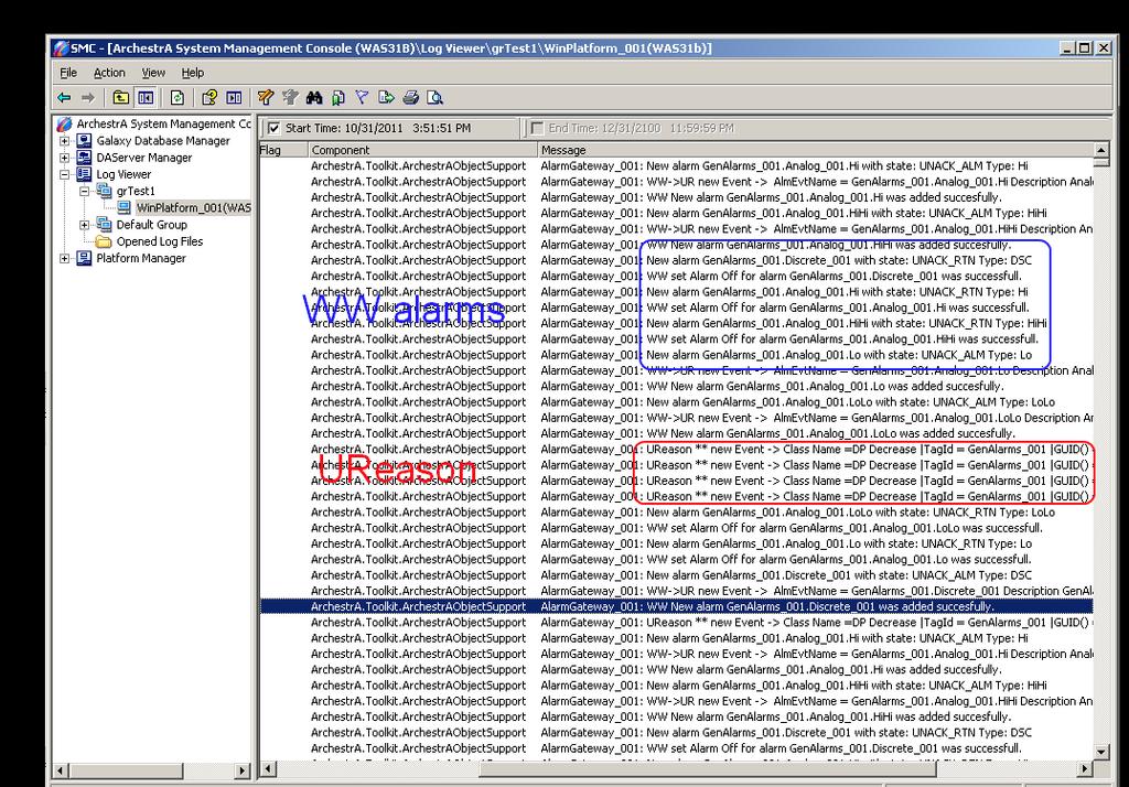
68 66 Advanced Troubleshooting For advanced troubleshooting there are possible to set Log Flags - following log flags are available: 1. General (attribute LogFlag.General) logs general logic diagnostic messages to SMC Logger. 2. WW Alarms (attribute LogFlag.WWAlarms) logs Wonderware alarms logic diagnostic messages to SMC Logger. 3. WW Events (attribute LogFlag.WWEvents) logs Wonderware event logic diagnostic messages to SMC Logger. 4. UReason - (attribute LogFlags.UReason) logs UReason logic diagnostic messages to SMC Logger. 5. License - (attribute LogFlags.License) logs licensing logic diagnostic messages to SMC Logger. Log flags are possible to configure in object editor: Log flags is possible also configure in runtime - see ArchestrA symbol Alarm_Gateway_Details from Klinkmann software demo:

69 67
 Deploy object host platform to install software update.")
70 68 Object upgrade procedure 1) Open ArchestrA IDE and import new version of Alarm Gateway object. 2) Object state is changed to Require software update. 3) Deploy object host platform to install software update. 4) Redeploy all Application Engine(s) that are hosting Alarm Gateway object(s) to load latest AG runtime libraries are loaded and used.
. 1) Undeploy all WinPlatforms that host AG object. 2) Delete all instances and templates from Galaxy.")
71 69 Object clean uninstall procedure This procedure can be used to fully uninstall the object. Can be used to downgrade to previous object version or to fix object upgrade issues. Note: must be performed on all WAS nodes where object was used/installed (IDE node, object nodes). 1) Undeploy all WinPlatforms that host AG object. 2) Delete all instances and templates from Galaxy. 3) Close ArchestrA IDE. 4) Uninstall manually AlarmGateway object assembles in case if they still are installed: a. Browse to folder C:\Windows\assembly, select all Assemblies named AlarmGatewayXX were XX is object version number e.g. 24. b. Open context menu by clicking right mouse button and select option Uninstall. 5) Delete WAS generated MSI installers that contains links to deleted/invalid files from: C:\Program Files (x86)\archestra\framework\filerepository\<your Galaxy Name>\Vendors Where is <Your Galaxy Name> your galaxy name e.g. grtest1 <User name> - currently logged user name user that was used to install object.
 Delete all")

72 70 6) Delete temp files from C:\Windows\Temp 7) Delete all entries that contains Alarm_Converter from Windows registry. 8) Restart PC.
73 71 WONDERWARE FINLAND Alarm Gateway Object Revision History Jun 2011 Rev 1.0 First Release Jun 2011 Rev 1.1 Alarm Group Hierarchy XML Associated Attribute and Description changed Sep 2011 Rev 1.2 Custom attributes and UReason gateway added. Sep 2011 Rev 1.3 Custom attributes for UReason gateway added. Mimic windows functionality added. Oct 2011 Rev 1.4 Installing the Alarm Gateway Object section modified. Troubleshooting and Object upgrade procedure sections added. Mar 2012 Rev 1.5 Exposed Alarm field feature added. Jul 2012 Rev 1.6 Updated Exposed attributes section. Aug 2012 Rev. 1.7 added section Custom Acked alarm comment field. Oct 2012 Rev. 1.9 Object version 17 updates. Dec 2012 Rev Added object clean uninstall procedure. Dec 2013 Rev Corrections in manual Table of Contents, headings and contents of all chapters.
Alarm Gateway Object for Wonderware Application Server User Guide Ver 1.x Rev 1.4 PR 00185
 Alarm Gateway Object for Wonderware Application Server User Guide Ver 1.x Rev 1.4 PR 00185 WONDERWARE FINLAND P.O. Box 38 FIN-00371 Helsinki Finland tel. int. + 358 9 5404940 fax int. + 358 9 5413541 www.wonderware.fi
Alarm Extension Pack for Wonderware Application Server Demo Guide Ver 1.0 Rev 1.0
 Alarm Extension Pack for Wonderware Application Server Demo Guide Ver 1.0 Rev 1.0 WONDERWARE FINLAND P.O. Box 38 FIN-00371 Helsinki Finland tel. int. + 358 9 5404940 fax int. + 358 9 5413541 www.klinkmann.com
Tech Note 836 Configuring an Alarm Acknowledgement Signature and Using the SignedAlarmAck() Script Function
 Script Function") Tech Note 836 Configuring an Alarm Acknowledgement Signature and Using the SignedAlarmAck() Script Function All Tech Notes, Tech Alerts and KBCD documents and software are provided "as is" without warranty
Tech Note 836 Configuring an Alarm Acknowledgement Signature and Using the SignedAlarmAck() Script Function All Tech Notes, Tech Alerts and KBCD documents and software are provided "as is" without warranty
ArchestrA Direct Connect
 Table of Contents ArchestrA Direct Connect... 1 Introduction... 1 ArchestrA Direct Connection... 1 ArchestrA Data Source Definition... 2 Data Source Definition... 2 Importing Alarms from ArchestrA... 6
Alarm Hot Backup Manager can use InTouch, Galaxy, or Galaxy_ as alarm providers when configuring an alarm Hot Backup Pair.
 Tech Note 925 Configuring Alarm Hot Backup Using Galaxy Provider All Tech Notes, Tech Alerts and KBCD documents and software are provided "as is" without warranty of any kind. See the Terms of Use for
Avigilon Control Center System Integration Guide
 Avigilon Control Center System Integration Guide with Velocity INT-HIRSCH-A-Rev3 Copyright 2013 Avigilon. All rights reserved. No copying, distribution, publication, modification, or incorporation of this
Avigilon Control Center 5 System Integration Guide
 Avigilon Control Center 5 System Integration Guide with Hirsch Velocity INT-HIRSCH-B-Rev1 2012 2014 Avigilon Corporation. All rights reserved. Unless expressly granted in writing, no license is granted
Avigilon Control Center 5 System Integration Guide
 Avigilon Control Center 5 System Integration Guide for Paxton Net2 Access Control Systems 2014 Avigilon Corporation. All rights reserved. Unless expressly granted in writing, no license is granted with
Avigilon Control Center 5 System Integration Guide. with STENTOFON AlphaCom. INT-STENTOFON-C-Rev1
 Avigilon Control Center 5 System Integration Guide with STENTOFON AlphaCom INT-STENTOFON-C-Rev1 2013 2014 Avigilon Corporation. All rights reserved. Unless expressly granted in writing, no license is granted
Introduction. Application Versions. Keys For An Alarm Query To Be Successful. Tech Note 821 Troubleshooting Wonderware Alarm Provider Query Issues
 Tech Note 821 Troubleshooting Wonderware Alarm Provider Query Issues All Tech Notes, Tech Alerts and KBCD documents and software are provided "as is" without warranty of any kind. See the Terms of Use
Avigilon Control Center System Integration Guide
 Avigilon Control Center System Integration Guide with Gallagher Command Centre INT-CARDAX-C-Rev3 Copyright 2013 Avigilon. All rights reserved. No copying, distribution, publication, modification, or incorporation
********************************************************* Installation ********************************************************* ATTENTION
 InTouch 7.11 Release Notes.txt Fri Sep 07 03:39:17 2001 1 ****************************** * InTouch 7.11 Release Notes * ****************************** *********************************************************
Avigilon Control Center System Integration Guide
 Avigilon Control Center System Integration Guide with Gallagher Command Centre INT-CARDAX-C-Rev2 Copyright 2011 Avigilon. All rights reserved. No copying, distribution, publication, modification, or incorporation
Bosch TCU Integration Module Administrator's Guide
 Bosch TCU Integration Module 1.0 - Administrator's Guide 10 Dec 2008 Rev 1.2 Table of Contents 1 Overview... 3 1.1 Compatibility...3 1.2 References...3 2 Installation... 4 3 Configuration... 5 3.1 System
STRIPEYFISH. Utilities for VMware Series. sfvalarms User Guide
 STRIPEYFISH Utilities for VMware Series sfvalarms User Guide S T R I P E Y F I S H sfvalarms User Guide Revision 3 StripeyFish 2013 www.stripeyfish.co.uk Table of Contents Introduction... 1 What is covered
Alarm Client. Installation and User Guide. NEC NEC Corporation. May 2009 NDA-30364, Revision 9
 Alarm Client Installation and User Guide NEC NEC Corporation May 2009 NDA-30364, Revision 9 Liability Disclaimer NEC Corporation reserves the right to change the specifications, functions, or features,
Avigilon Control Center System Integration Guide
 Avigilon Control Center System Integration Guide with Picture Perfect 4 INT-PP4-A-Rev1 Copyright 2012 Avigilon. All rights reserved. No copying, distribution, publication, modification, or incorporation
Platform Services BACnet Alarm Management
 Description: Guide to understanding and setting up BACnet Alarms, visualizing real-time and historical BACnet alarms using AlarmWorX64 Viewer and logging them to SQL database using AlarmWorX64 Logger OS
Avigilon System Integration Guide. Avigilon Control Center with AMAG Symmetry Security Management System 7.0
 Avigilon System Integration Guide Avigilon Control Center with AMAG Symmetry Security Management System 7.0 2013-2016, Avigilon Corporation. All rights reserved. AVIGILON, the AVIGILON logo, HDSM, HIGH
Avigilon Control Center 5 System Integration Guide
 Avigilon Control Center 5 System Integration Guide with Lenel Facility Commander Wnx INT-FCWNX-A-Rev1 2010 2014 Avigilon Corporation. All rights reserved. Unless expressly granted in writing, no license
Milestone SMI Intrepid II Perimeter Module 1.1 User s Manual
 Milestone SMI Intrepid II Perimeter Module 1.1 User s Manual Target Audience for this Document This document is aimed at system users and provides descriptions on how to install and maintain the Milestone
Avigilon System Integration Guide. for the Avigilon Control Center and Access Control Manager
 Avigilon System Integration Guide for the Avigilon Control Center and Access Control Manager 2014-2017, Avigilon Corporation. All rights reserved. AVIGILON, the AVIGILON logo, ACC, AVIGILON CONTROL CENTER,
Niagara4 Technical Certification Program Student Guide DAY 1 DAY 2
 Niagara4 Technical Certification Program Student Guide DAY 1 Welcome Course Introduction Platforms & Stations Niagara4 Fundamentals Simple Logic: Hot Water Pump Control (Thermostatic) Simple Logic: Hot
Alarm Monitoring and Management
 CHAPTER 9 This chapter describes Cisco Transport Controller (CTC) alarm management. To troubleshoot specific alarms, refer to the Cisco ONS 15310-CL Troubleshooting Guide. Chapter topics include: 9.1 Overview,
BlackBerry AtHoc Networked Crisis Communication Siemens Indoor Fire Panel Installation and Configuration Guide Release Version 7.
 BlackBerry AtHoc Networked Crisis Communication Siemens Indoor Fire Panel Installation and Configuration Guide Release Version 7.3, October 2017 Copyright 2017 BlackBerry Limited. All Rights Reserved.
Procidia iware AlarmWorX32. AlarmWorX32 Viewer January 2010
 Procidia iware AlarmWorX32 AlarmWorX32 Viewer Siemens Protection AG 2008. notice All / Copyright rights reserved. notice Introduction / Contents Procidia iware is an operator interface software designed
LineGuard 2300 Program User Manual (FloBoss 107)
") Form A6251 Part Number D301346X012 November 2012 LineGuard 2300 Program User Manual (FloBoss 107) Remote Automation Solutions Revision Tracking Sheet November 2012 This manual may be revised periodically
Form A6251 Part Number D301346X012 November 2012 LineGuard 2300 Program User Manual (FloBoss 107) Remote Automation Solutions Revision Tracking Sheet November 2012 This manual may be revised periodically
Centroid Snet 2. Battery Management Software. User Manual V1.1. Eagle Eye Power Solutions, LLC Keeping an Eye on Your Critical Power!
 Eagle Eye Power Solutions, LLC Keeping an Eye on Your Critical Power! Centroid Snet 2 Battery Management Software User Manual V1.1 www.eepowersolutions.com Tel: 1-877-805-3377 info@eepowersolutions.com
Avigilon System Integration Guide. for the Avigilon Control Center and Access Control Manager
 Avigilon System Integration Guide for the Avigilon Control Center and Access Control Manager 2014-2016, Avigilon Corporation. All rights reserved. AVIGILON, the AVIGILON logo, AVIGILON CONTROL CENTER,
Guide to the ArchestrA Alarm Control Invensys Systems, Inc.
 Guide to the ArchestrA Alarm Control Invensys Systems, Inc. Revision A Last Revision: 10/17/08 Copyright 2008 Invensys Systems, Inc. All Rights Reserved. All rights reserved. No part of this documentation
Tech Data Sheet D01662GB0_Esgraf 4.1 and Configuration Server 30/2011 2/(5)
") Tech Data Sheet D01662GB1_Esgraf 4.1 and Configuration Server 30/2011 1/(5) Esgraf 4.1 graphical user interface, configuration server and fire detectors contamination monitoring Esgraf 4.1 ESGRAF is a
Tech Data Sheet D01662GB1_Esgraf 4.1 and Configuration Server 30/2011 1/(5) Esgraf 4.1 graphical user interface, configuration server and fire detectors contamination monitoring Esgraf 4.1 ESGRAF is a
WorkstationST* Alarm Viewer
 GEI-100620U WorkstationST* Alarm Viewer Instruction Guide These instructions do not purport to cover all details or variations in equipment, nor to provide for every possible contingency to be met during
Managing Network Alarms and Events
 9 CHAPTER Prime Performance Manager allows you to view alarms and events that occur in your network. The following topics provide information about displaying network alarms and events: Displaying Active
Simplex Panel Interface Guide
 Simplex Panel Interface Guide February 2016 SATEON Software Integrations Simplex Panel Interface Guide Issue 1.0, released February 2016 Disclaimer Copyright 2016, Grosvenor Technology. All rights reserved.
2017/11/16 P a g e 1
 2017/11/16 P a g e 1 Contents What s New... 2 Fixes... 3 Driver Updates... 3 New Sensors... 3 New Features... 3 How To... 4 Security... 4 Auditing... 6 Smart UI/MAPS Title 21 CFR Part 11 Auditing... 6
Network Hardware and wiring (quiz)...
...") 4120 Network/TSW (FA049) Course Agenda Day 1 Course Introduction (Presentation)... 8:00 am to 8:30 am Break Module 1 Installing and Configuring Network Software Applications 4120 New Network Programmer
4120 Network/TSW (FA049) Course Agenda Day 1 Course Introduction (Presentation)... 8:00 am to 8:30 am Break Module 1 Installing and Configuring Network Software Applications 4120 New Network Programmer
This Tech Note provides detailed procedures to configure Remote Response objects to trigger an alarm and acknowledge it via or SMS.
 Tech Note 856 Getting Started with the Remote Response Object (RRO) All Tech Notes, Tech Alerts and KBCD documents and software are provided "as is" without warranty of any kind. See the Terms of Use for
RADview-EMS/TDM. Element Management System for TDM Applications Optimux RAD Data Communications Publication 07/04
 RADview-EMS/TDM Element Management System for TDM Applications Optimux-1553 1994 2004 RAD Data Communications Publication 07/04 Contents Chapter 1. Introduction 1.1 Overview... 1-1 1.2 System Features...
SIMATIC IPC DiagBase SIMATIC. Industrial PC SIMATIC IPC DiagBase. Introduction. DIAG software components. Quick-Start Guide
 Introduction 1 DIAG software components 2 SIMATIC Industrial PC Operating Manual Quick-Start Guide 3 Hardware and software requirements 4 Installing and removing the software 5 Description of the Management
Security Escort Central Console Software SE2000 Series
 Release Notes Security Escort Central Console Software SE2000 Series Table of Contents 1 Security Escort v2.18.1.0... 2 1.1 Enhancements... 2 1.2 Errors Fixed... 2 1.3 Known Limitations and Restrictions...
Ademco Vista Alarm Panel
 System Galaxy Quick Guide CONFIGURATION AND OPERATION Ademco Vista Alarm Panel JAN 2018 SG 10.5.6 System Galaxy Quick Guide For Ademco Vista Panel Configuration & Operation 2nd edition JAN 2018 Information
Alarm Monitoring and Management
 CHAPTER 10 This chapter describes Cisco Transport Controller (CTC) alarm management. To troubleshoot specific alarms, refer to the Cisco ONS 15310-MA SDH Troubleshooting Guide. Chapter topics include:
Multistate Alarm. Introduction
 Object Dictionary 1 Multistate Alarm Introduction The Multistate Alarm object adds the alarming capability for a Boolean or multistate attribute for any object, such as the Present Value of a Binary Input
Managing Network Alarms and Events
 10 CHAPTER Prime Performance Manager allows you to view alarms and events that occur in your network. The following topics provide information about displaying network alarms and events: Displaying Active
Oracle Communications Performance Intelligence Center
 Oracle Communications Performance Intelligence Center System Alarms Guide Release 10.2.1 E77506-01 June 2017 1 Oracle Communications Performance Intelligence Center System Alarms Guide, Release 10.2.1
SIMATIC IPC DiagBase SIMATIC. Industrial PC. Introduction. DIAG software components. Quick-Start Guide. Hardware and software requirements
 Introduction 1 DIAG software components 2 SIMATIC Industrial PC Operating Manual Quick-Start Guide 3 Hardware and software requirements 4 Installing and removing the software 5 Description of the Management
Monitor Alarms and Events
 This chapter contains the following topics: What Are Alarms and Events?, page 1 How are Alarms and Events Created and Updated?, page 2 Find and View Alarms, page 3 Set Alarm and Event Management Preferences,
Yokogawa DX Ethernet Driver Help Kepware Technologies
 Yokogawa DX Ethernet Driver Help 2012 Kepware Technologies 2 Table of Contents Table of Contents 2 4 Overview 4 Device Setup 5 Communications Parameters 7 Optimizing Your Ethernet Communications 9 Data
Moxa Proactive Monitoring User s Manual
 User s Manual Edition 2, May 2016 www.moxa.com/product 2016 Moxa Inc. All rights reserved. User s Manual The software described in this manual is furnished under a license agreement and may be used only
HikCentral Web Client. User Manual
 HikCentral Web Client User Manual Legal Information User Manual 2018 Hangzhou Hikvision Digital Technology Co., Ltd. About this Manual This Manual is subject to domestic and international copyright protection.
FUNCTIONAL DESCRIPTION DIS01
 We reserve all rights in this document and in the information contained therein. Reproduction, use or disclosure to third parties without express authority is strictly forbidden. ABB FUNCTIONAL DESCRIPTION
AK-CS On Board Guide
 MAKING MODERN LIVING POSSIBLE AK-CS On Board Guide electronic controls & sensors About this guide The AK-CS On Board guide highlights the use of the RMT tool, allowing remote software management. Consult
HikCentral Web Client. User Manual
 HikCentral Web Client User Manual Legal Information User Manual 2018 Hangzhou Hikvision Digital Technology Co., Ltd. About this Manual This Manual is subject to domestic and international copyright protection.
 Configuring Messages and Alarms in WinCC (TIA Portal) Extension with S7-1200/S7-1500 WinCC V14 SP1 https://support.industry.siemens.com/cs/ww/en/view/62121503 Siemens Industry Online Support Siemens AG
PotterNet Fire & Facility Supervising Station
 Features Connect up to 1000 Potter panels in a single building, local campus, or multiple sites worldwide using LAN/WAN/Internet Native Ethernet networking connectivity with fire panels and client stations,
FCD-wire Contents. List of Figures
 FCD-wire Contents FCD-X21 Configuration 1 Introduction... 1 2 Opening the FCD Application... 1 3 FCD Window... 2 4 FCD LEDs... 3 5 Configuration Operations... 4 FCD Info...4 FCD System Info...5 FCD Interface
Alarm Coordination Connected Components Building Block. Quick Start
 Alarm Coordination Connected Components Building Block Quick Start Important User Information Solid state equipment has operational characteristics differing from those of electromechanical equipment.
IndigoVision. GAI-Tronics Integration Module. Administrator's Guide
 IndigoVision GAI-Tronics Integration Module Administrator's Guide GAI-Tronics Integration Module THIS MANUAL WAS CREATED ON 10 APRIL 2013. DOCUMENT ID: IU-IM-MAN019-1 Legal Considerations LAWS THAT CAN
Manual# User s Manual. 200E Series. DCU 210E/208E Diesel Engine Control Unit RP 210E Remote Panel
 Manual# 1006494 User s Manual 200E Series DCU 210E/208E Diesel Engine Control Unit RP 210E Remote Panel User's Manual Rev. 1.0 Marine Pro 200E Series ~~~ DCU 210E Diesel Engine Control Unit DCU 208E Diesel
Alarm Monitoring and Management
 CHAPTER 14 This chapter describes Cisco Transport Controller (CTC) alarm management. To troubleshoot specific alarms, refer to the Cisco ONS 15454 Troubleshooting Guide. Chapter topics include: 14.1 Overview,
FUNCTIONAL DESCRIPTION AIS01
 We reserve all rights in this document and in the information contained therein. Reproduction,use or disclosure to third parties without express authority is strictly forbidden. ABB AB; 2002 FUNCTIONAL
Alarms and Events. Defining Alarm Conditions. Database-Generated Alarms
 9 Defining Alarm Conditions Database-Generated Alarms The LookoutDirect alarm service keeps track of error messages and any process elements you have defined alarm conditions for. You can define alarm
BOSCH GV4 Alarm Panel
 System Galaxy Quick Guide CONFIGURATION AND OPERATION BOSCH GV4 Alarm Panel SG 10.2 (or later) NOV 2012 This is a Galaxy Product Interface Guide. Information in this document is subject to change without
SIMATIC. Industrial PC SIMATIC IPC DiagBase V Introduction. SIMATIC IPC DiagBase software components. Quick-Start Guide
 Introduction 1 SIMATIC IPC DiagBase software components 2 SIMATIC Industrial PC Operating Manual Quick-Start Guide 3 Hardware and software requirements 4 Installing and removing the software 5 Displaying
Alarm Monitoring and Management
 14 CHAPTER This chapter explains how to manage alarms with Cisco Transport Controller (CTC). To troubleshoot specific alarms, refer to the Cisco ONS 15454 SDH Troubleshooting Guide. Chapter topics include:
Supervisor Standard Edition
 Supervisor Standard Edition Installation Manual Heat-Tracing Controller Configuration and Monitoring Software INSTALL-119 (Europe) 1 / 18 Contents Section 1 Introduction...3 1.1 Welcome...3 1.2 Vital Information...3
ESB Tools Reference Guide. Version: CR2
 ESB Tools Reference Guide Version: 1.1.0.CR2 1. Introduction... 1 1.1. What is ESB?... 1 1.2. Other relevant resources on the topic... 1 2. ESB Support... 3 2.1. ESB Tools Installation... 3 2.2. Creating
Running IGSS as an Operator, Part One
 Running IGSS as an Operator, Part One Contents Duration We want to see how a completed IGSS SCADA system appears to plant operator personnel to get an idea of the various elements in the system and how
ESB Tools Reference Guide. Version: GA
 ESB Tools Reference Guide Version: 1.1.0.GA 1. Introduction... 1 1.1. What is ESB?... 1 1.2. Other relevant resources on the topic... 1 2. ESB Support... 3 2.1. ESB Tools Installation... 3 2.2. Creating
Alarm Benchmark Module By Konnection Introduction Overview Description
 Introduction 1 Overview 1 Description 1 Known Compatible Database Versions 1 Supported Ignition Versions 2 Component Listing 2 Getting Started 2 Requirements 2 How to Use 2 Terminology 2 Trial Limitations
Technical Specification. For. Arla Tankvagt
 Technical Specification For Arla Tankvagt Tankvagt - technical specifications ver. 4.2 CONTENT 1 DOCUMENT CONTROL...2 1.1 Revision History...2 1.2 Reviewers...2 1.3 Related Documents...2 2 INTRODUCTION...3
i-vu CCN 4.0 Owner s Guide
 i-vu CCN 4.0 Owner s Guide CARRIER CORPORAION 2007 A member of the United echnologies Corporation family. Stock symbol UX. 11-808-377-01 07/07 able of Contents ACCESSING YOUR SYSEM... 3 YOUR SYSEM DEAILS...
Trident User s Manual
 Labkotec Oy Myllyhaantie 6 33960 Pirkkala FINLAND Tel. +358 (0)29 006 260 18.05.2017 Fax +358 (0)29 006 1260 Internet: www.labkotec.fi 34 pages Trident Copyright 2017 Labkotec Oy 1/34 TABLE OF CONTENTS
Introduction. Introduction
 M-Alarm User s Guide 1-1 Chapter 1 Introduction Introduction M-Alarm allows the user to view, store, and manipulate current alarms received by N1 or BACnet Object Linking and Embedding (OLE) for Process
Raytec Avigilon Integration User Guide Integrating Raytec Network Illuminators with Avigilon Control Center Document Revision 2.0
 Raytec Avigilon Integration User Guide Integrating Raytec Network Illuminators with Avigilon Control Center Document Revision 2.0 Table of Contents 1 INTRODUCTION... 3 1.1 OVERVIEW... 3 1.2 SOFTWARE COMPONENTS...
Supervisor OPERATIONS MANUAL. Heat-Tracing Controller Configuration and Monitoring Software. Versions up to 2.7xx. INSTALL-118 (Europe)
") OPERATIONS MANUAL Supervisor Heat-Tracing Controller Configuration and Monitoring Software Versions up to 2.7xx INSTALL-118 (Europe) THERMAL MANAGEMENT Raychem-AR-H57576-SupervisorOperations-EN-1706 THERMAL
OPERATIONS MANUAL Supervisor Heat-Tracing Controller Configuration and Monitoring Software Versions up to 2.7xx INSTALL-118 (Europe) THERMAL MANAGEMENT Raychem-AR-H57576-SupervisorOperations-EN-1706 THERMAL
CompleteView Alarm Client User Manual. CompleteView Version 4.6.1
 CompleteView Alarm Client User Manual CompleteView Version 4.6.1 Table of Contents Introduction... 1 Overview...2 System Requirements...2 Configuration... 3 Starting the Alarm Client...3 Menus...3 File
Millennium Xtra. Millennium ATMA setup and configuration guide. May Millennium Group, Inc.
 Millennium Xtra Millennium ATMA setup and configuration guide May 16 2017 Millennium Group, Inc. 16 Tech Circle Natick, MA 01760 P: 508-655-1340 F: 508-651-2902 Millennium ATMA setup and configuration
Wonderware InTouch HMI Alarms and Events Guide
 Wonderware InTouch HMI Alarms and Events Guide 10/14/15 All rights reserved. No part of this documentation shall be reproduced, stored in a retrieval system, or transmitted by any means, electronic, mechanical,
Patriot Systems Limited
 COPYRIGHT 1997 - The Patriot Systems Ltd. Patriot Alarm Monitoring Automation Package is licensed for use on one computer, by the original person, or company, or organization whose name is registered with
Siemens Drives & PLCs
 Introduction 1 DIAG software components 2 SIMATIC Industrial PC Operating Manual Quick-Start Guide 3 Hardware and software requirements 4 Installing and removing the software 5 Description of the Management
Before you install ProSeries Express Edition software for network use
 Before you install ProSeries Express Edition software for network use The following pages describe system requirements and other information you need to know before installing ProSeries Express Edition
Technical Publications. FactoryTalk Alarms and Events System Configuration Guide
 Technical Publications FactoryTalk Alarms and Events System Configuration Guide Important user information Read this document and the documents listed in the additional resources section about installation,
Configuring Thresholds
 10 CHAPTER The following topics provide information about configuring thresholds in Cisco Prime Performance Manager: Creating Thresholds in Prime Performance Manager, page 10-1 Managing Thresholds, page
Operation Manual Fighter ProVision Software. Version: 0.0 Revision: 1
 Operation Manual Fighter ProVision Software Version: 0.0 Revision: 1 TABLE OF CONTENTS 1. Introduction 5 2. Software Installation 5 3. PC Users 6 3.1 Introduction 6 3.2 Default Code 6 3.3 Edit PC User
D-Link Central Management System
 D-Link Central Management System This seamless management of digital video, audio and data is a powerful solution for large scale installations The D-Link Central Management System is a powerful system
ibox Modbus Server Gateway for the integration of Notifier ID3000 / ID3002 / ID60 / ID50 fire panels in Modbus enabled monitoring and control systems
 Honeywell Life Safety Iberia C/Pau Vila 15-19; 08911 Badalona Barcelona T. 902 03 05 45; Internacional:+34932424236 www.honeywelllifesafety.es infohlsiberia@honeywell.com ibox Modbus Server Gateway for
Milestone XProtect Alarm Matrix Integration 1.0
 Milestone XProtect Alarm Matrix Integration 1.0 Milestone XProtect Alarm Matrix Integration 1.0 Target Audience This document is aimed at system users and provides descriptions on how to install, configure
User Manual Doc.Ref : JA-KNX-UM. JA-KNX Jablotron KNX Interface ELAUSYS JA-KNX. KNX Interface for Jablotron alarm system.
 Page : 1 of 17. ELAUSYS JA-KNX KNX Interface for Jablotron alarm system User Manual Document history Version. Date Author Comment 1.00 24-JUN-2017 NDE First issue 1.01 14-NOV-2017 NDE Support for user
This technical update applies to Pro-Watch Software Release 3.5 and later.
 Technical Update Pro-Watch Software Intercom Product Support Product Versions This technical update applies to Pro-Watch Software Release 3.5 and later. Overview Intercom systems consist of master stations,
DeltaV Analyze. Introduction. Benefits. Continuous automated DeltaV System alarm system performance monitoring
 DeltaV Distributed Control System Product Data Sheet December 2016 DeltaV Analyze Continuous automated DeltaV System alarm system performance monitoring Trends of alarms, events, and user actions Identification
FactoryTalk Alarms and Events. System Configuration Guide
 FactoryTalk Alarms and Events System Configuration Guide Important user information Read this document and the documents listed in the additional resources section about installation, configuration, and
725B Configuration Software Manual
 725B Configuration Software Manual REV DATED DESCRIPTION AUTHOR APPROVED 0 09-03-10 First Issue P.Cartmell Page 1 of 80 SECTION 1 - SOFTWARE INSTALLATION... 5 725B ConfigurationSoftware Installation...
System Galaxy Quick Guide
 System Galaxy Quick Guide CONFIGURATION AND OPERATION Integrating CCTV with System Galaxy JAN 2019 SG 11.1.0.2 System Galaxy Quick Guide For CCTV Integration Configuration & Operation Information in this
FortiNAC. Lightspeed Single Sign-On Integration. Version: 8.x Date: 8/29/2018. Rev: B
 FortiNAC Lightspeed Single Sign-On Integration Version: 8.x Date: 8/29/2018 Rev: B FORTINET DOCUMENT LIBRARY http://docs.fortinet.com FORTINET VIDEO GUIDE http://video.fortinet.com FORTINET KNOWLEDGE BASE
DEVELOPMENT OF THE TANGO ALARM SYSTEM
 10th ICALEPCS Int. Conf. on Accelerator & Large Expt. Physics Control Systems. Geneva, 10-14 Oct 2005, WE3B.1-70 (2005) DEVELOPMENT OF THE TANGO ALARM SYSTEM L. Pivetta Sincrotrone Trieste, Trieste, Italy
ModSync Sequencing System Installation & Operation Manual. For use with Fulton Steam Boilers.
 ModSync Sequencing System Installation & Operation Manual For use with Fulton Steam Boilers. Revision 3.0 8/21/2008 - 2 - Table of Contents Introduction Page 4 Features Page 4 Sequence of Operation Page
User Manual. Dryer Controller M720
 User Manual Dryer Controller M720 Hardware version 1.00 Software version 1.00 Preliminary version Manual M720 Dryer controller Page 1 of 42 Document history Preliminary version: - Created in April, 2009
Milestone XProtect Alarm Matrix Integration 1.0
 Milestone XProtect Alarm Matrix Integration 1.0 Milestone XProtect Alarm Matrix Integration 1.0 Target Audience This document is aimed at system users and provides descriptions on how to install, configure
CBI-064. User Manual. Caddx to KNX-BUS Interface
 CBI-064 Caddx to KNX-BUS Interface User Manual GDS Intelligence in Buildings El. Venizelou 116 Nea Erithrea 14671 Tel: +30 2108071288 Email: info@gds.com.gr Web: gds.com.gr Contents 1 Device Description...