GradeShift UDL QUICK GUIDE & INSTRUCTION MANUAL
|
|
|
- Marianna Clarke
- 5 years ago
- Views:
Transcription

1 GradeShift UDL QUICK GUIDE & INSTRUCTION MNUL
2 This guide contains information taken from the UDL Installation Manual. full copy of the manual can be downloaded from Please note that all page references made in this guide refer to the UDL Instruction Manual. 2
3 SiTe SurVey it is strongly recommended that a site survey is conducted prior to installation of a DualCom to confirm that an adequate radio (gsm/gprs) signal strength is available at the site. efore visiting the site, call CSL Technical Support on the contact details below and ask for a GPRS signal strength prediction. For this, you will need to have the Post Code of the site available and you will be advised if there is GPRS radio coverage at the proposed site. Use of the GPRS Signal Strength Test Kit is recommended to survey the proposed site for adequate signal strength and to locate the point of strongest signal. See erial Siting on Page 12 for more information. Make a note of this point and use it when installing the DualCom aerial. If there is no GPRS radio coverage at the proposed site, the DualCom will be unable to use the radio path for alarm reporting, polling or programming of the DualCom or the associated Control Panel. If there is an insufficient quantity of base stations or the radio signals they provide are weak the radio path will be unreliable. It is recommended that DualCom has a minimum of 2 base stations available with 40% or greater signal strength on one and at least 30% on the other base station. TeChNiCl SuPPorT If you have installed the DualCom in accordance with these instructions, checked all the above points but are still experiencing problems please contact CSL Technical support. CSl Technical Support helpdesk UK Tel: +44 (0) Ireland Tel: support@csldual.com Hours: to weekdays, to Saturday. The CSL web site: contains the latest copies of all manuals for all CSL products. Please ensure that you are working from the latest version. You can also download associated information and software samplers. Sales, shipping and contact information is here too. 3
4 instlltion 1. Site the aerial at the point of strongest signal ensuring that it is within the protected area. This point will be identified during the Site Survey (see previous page). The best place of aerial installation is usually the highest point in the building and well away from metal roofs and metal walls. See erial Siting on Page 12 for more information.the DualCom is supplied with the CS2057 aerial. This includes a 5m coax lead and is pre-fitted with a plug for connection to the DualCom. 2. Totally power down the Control Panel, both mains and battery. 3. Where required, fit the CS2351 Expansion Card to the DualCom. lternatively, for dual path operation, fit the CS5355 Wired LN(IP) Card or CS5385 PSTN Card. ll Cards include 4 additional pin triggering input terminals and 4 remotely controlled output terminals. See pages Note: Only one of these cards can be fitted at a time. Where a LN(IP) Card is fitted, connect the LN Card to the LN using a Cat 5 (or higher grade) cable fitted with an RJ45 plug. See pages Where a PSTN Card is fitted, connect the PSTN Card to the PSTN telephone line. See Pages For security installations, only use serial connection for other equipment that is using the same telephone line. 4. Connect the DualCom to the Control Panel: Where pin triggering is used, connect the input triggers to the DualCom s terminals. See pages Some panels have a plug-on digi-modem conforming to the Scantronic plug-on footprint. Where this is available, many connections required between the panel and the DualCom may be achieved using the CS2325 Plug-on dapter. See pages Where Dial Capture is used, connect the DualCom Dial Capture terminals to the Control Panel s digi-modem telephone line terminals. See page 18. Where the 485 us is used, (Honeywell Galaxy, Dimension & Flex panels) plug the supplied CS pin lead into the DualCom s 485 us Port and onto the panel s matching 485 con- nection. See page 17. Where the 232 Serial Port is used, connect the supplied CS pin plug into the DualCom s 232 Serial Port and connect the wires to the panel s serial port connection. Note that the Tx and Rx wires must not be swapped when making connection. See page 17. Note: Where connection to the panel is by Dial Capture, 485 us or 232 Serial then pin triggering to the DualCom s input terminals is also active. These inputs may be triggered by the same or another control panel, e.g. a Fire panel. Note: regardless of the Panel/DualCom connection method used, always connect DualCom s input 4 from a Set/unset output on the Control Panel. See ppendix Connect to the output relays Fault and ux as required. When installing to PD6662 standards, ensure that fault reporting from the DualCom to the Control Panel is configured as required. See pages Connect the aerial to the DualCom. See page 13. 4
5 instlltion (CoNTiNueD) 7. Connect the 9-30v terminals to the Control Panel or Power Supply output (often called ux supply or DC power ). See Fig 2 and page 21. (This step is not required when the CS2325 Plug-on dapter is used) 8. Reconnect the mains supply to the control panel. The DualCom is now ready for testing. SySTem TeSTiNg ensure you have informed your rc that you are ready to test your DualCom. 1. When the Control Panel is powered-up, the DualCom will initialise. This will take about 1 minute. ll LED indications showing operation status and fault conditions are listed in ppendix Use the & buttons to start the Input Learning feature. See ppendix 1, Tables 30 & 31. Input Learning is fully described further on in this leaflet. 3. Where the CS2385 PSTN Card or the CS2355 LN(IP) Card is fitted, use the & uttons to enable the Card. See ppendix 1, Table 32. Use the & uttons to disable the Telephone Line where this has not been fitted. See ppendix 1, Table 32. Use the & uttons to select a telephone pre-digit 9 when the DualCom is connected to an extention of a PX. See ppendix 1, Table To test all communication paths to the RC, use the & uttons to start the test calls. This will cause the DualCom to send a test signal to the RC on all active paths, e.g. GPRS (radio), Wired LN (internet/ip) and the PSTN telephone path. See ppendix 1, Table 30. During communication the Radio & Wired path LEDs will flash and the display will show C1, C2, C3 and to indicate the progress of the call. See ppendix 1, Tables 29 and Contact the RC to ensure that all paths have successfully sent test calls and that the RC operator can see them on their screen. 6. From the Control Panel s keypad, trigger calls for all used channels, e.g. Intruder, Open/close, P/ and Fire circuits. Note: Test calls are sent on all paths to the RC. When alarm calls are sent, all DualCom paths are activated, but only one alarm call will be received. This will be via the path that is the first to send the alarm call to the RC. 7. Simulate a path failure and confirm that it is detected and signalled to the RC. For quicker testing of PSTN, LN(IP) and radio path failure detection, use the & uttons to select Test te mode. Detection of path failures will now be much quicker than for normal operation. See ppendix 1, Table 30. Simulate a Radio path failure. Disconnect the aerial lead from the DualCom and wait until the fault is actioned by the DualCom (typically 50 seconds). Observe the radio fail message being sent via the PSTN or LN(IP) path. Replace the aerial lead in the aerial connector on the DualCom. Then observe the restore message being sent via the radio path. 5
6 SySTem TeSTiNg (CoNTiNueD) Where the PSTN Card is fitted, simulate a PSTN path failure. Remove the PSTN wires from the PSTN Card s & terminals then wait until the fault is actioned by the DualCom (typically 10 seconds). Observe the PSTN fail message being sent via the radio path. Replace the PSTN wires in the PSTN Card s & terminals. Then observe the restore message being sent via the radio path. Where the LN(IP) Card is fitted, simulate a wired IP path failure. Remove the LN RJ45 connector from the LN(IP) Card then wait until the fault is actioned by the DualCom (typically 10 seconds). Observe the LN(IP) path fail message being sent via the radio path. Replace the LN RJ45 connector from the LN(IP) Card. Then observe the restore message being sent via the radio path. The Test te mode will be automatically disabled after 10 minutes and whenever the DualCom is reset or powered down & up. Detection of PSTN, LN and radio path failures will return to their preset speed. 8. Contact your RC to confirm that all signals have been received. Ensure that all Restore signals are received when the DualCom input terminals return to their quiescent value. 9. If the quiescent (non-active) states of the input terminals are incorrect, i.e. positive applied/removed is inverted, then the RC will report that the larm/restore or Open/Close is the wrong way round. To correct this, use the & buttons to start the Input Learning feature. See ppendix 1, Tables 30 & 31. Input Learning is fully described on page 16. Other questions regarding DualCom programming and operation should be made to CSL Technical Support. See page To meet EN standards, DualCom is supplied with monitoring (polling) enabled on all paths. See page 11. Polling will start automatically 45 minutes after power-up. 11. Note the SIM Card number Serial Number, e.g , the NVM chip number and any security access numbers on the site records that will be stored at your office. 12. When not communicating or indicating errors, the DualCom s display will show the received radio signal strength as a percentage. E.g. 47 = 47%. Reliable operation is unlikely with a low signal strength (below 40%). If the display shows that the signal strength is low, you should improve the signal strength. See erial Siting on page 13. flashing signal strength display indicates that signal strength that may be too low for reliable operation. 13. Your DualCom is now fully tested. DualCom may be supplied as a Single path (e.g. G2r, G3r) signalling device, or a Dual path (e.g. G2, G3, G4) signalling device. Where DualCom is supplied as a Dual path signalling device and the product is not fully installed to the appropriate dual path specification then the product may not operate as designed. 6
7 eril SiTiNg lwys do a site survey to find an area of strong signal before installation. Installing a DualCom with a weak signal is bad installation practice. The DualCom is likely to suffer signal failure causing wasted site vists, time & money. The aerial should be mounted vertically at the point of strongest signal. This is usually the highest point in the building (often the loft area). large metal structures can affect radio signals. void installing the aerial directly under metal roofs or within metal skinned buildings because this will reduce the signal strength and may inhibit operation completely. If this is unavoidable, the strongest signal will be found away from the metal roof or close to large external windows or skylights. void installing the aerial close (2 metres) to cable runs, ducting, structural metalwork, metal pipes, water tanks and electronic equipment, e.g. photocopiers, fax machines etc. These can have similar effects to metal roofs. Reliable operation is unlikely with a low signal strength. If the DualCom s display shows that the signal strength is low (the signal strength value will flash), you should improve the signal strength. This may be achieved by repositioning the aerial. The aerial lead should not be cut, therefore repositioning the aerial may require that the DualCom is also repositioned. To aid repositioning, the optional extra CS2056 erial Extention lead is available. This is 5 metres long. When used, it will reduce the signal by approx 10%. Therefore, the aerial must be re-positioned to improve the signal strength by at least 10% in order to provide any benefit. n insufficient quantity of base stations or weak radio signals from them, will result in an unreliable radio path. It is recommended that DualCom has a minimum of 2 base stations available with 40% or greater signal strength on one and at lease 30% on the other. gprs Signal Strength Test Kit is ideal for surveying a site. This handheld unit can check the availability, signal strength and interference status of all surrounding ase Stations on all networks. In addition, it will identify the best location for a DualCom aerial within the building, help to avoid sources of interference and can confirm the availability of a GPRS radio service at the proposed site. See page 38. Where a GPRS Signal Strength Test Kit is unavailable, a DualCom with an aerial and fully charged battery may be used to locate the point of strongest signal. Ensure that the DualCom is fully operational then walk around the site carrying the equipment and observing the signal strength display on the DualCom. This method can not provide information on the availability, signal strength and interference status of all radio ase Stations in the surrounding area or those on other networks. For this, use of the GPRS Signal Strength Test Kit is recommended. lternatively, a mobile phone may be used. The signal strength indicator is normally a bar or line at the side of the display on the mobile telephone. Note: The mobile phone will only show the signal strength of the network to which it is connected. This method can not provide information on the availability, signal strength and interference status of all radio ase Stations in the surrounding area or those on other networks. For this, use of the GPRS Signal Strength Test Kit is recommended. When you have identified the point of the strongest signal, make a note of this point and use it when installing the DualCom aerial. remember: it is always easier to find the point of strongest signal before the equipment is installed. 7
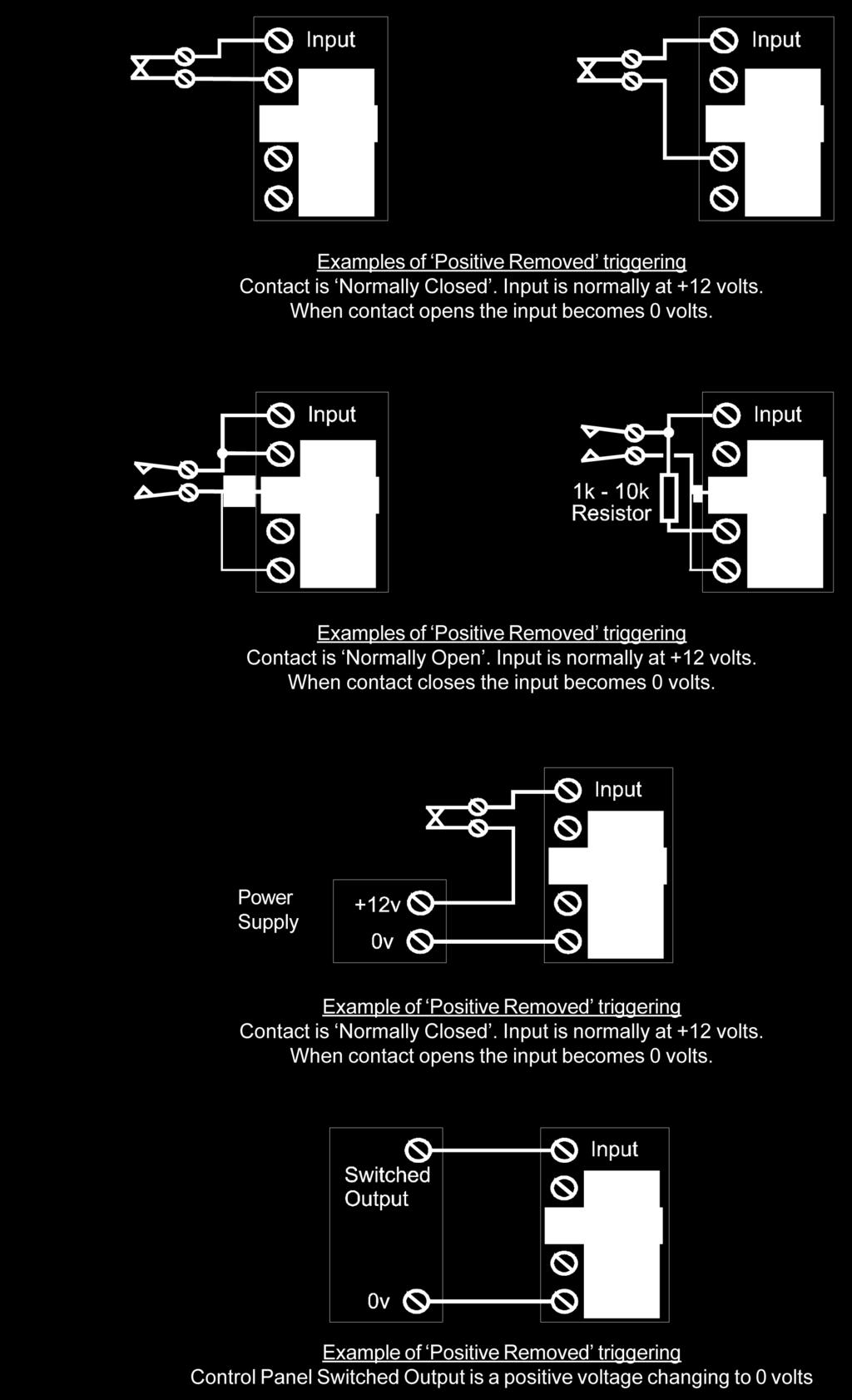
 on each input terminal as required.")
8 CoNNeCTiNg The DulCom To CoNTrol PNel (CoNTiNueD) input Terminals Self learning 1. Setup the inputs non-active conditions by connecting a positive voltage or no voltage (0v) on each input terminal as required. This is easily achieved by connecting the Control Panel outputs to the DualCom s terminal inputs, then put the Control Panel in the day state with no activated detectors and all alarm conditions reset. Ensure that the Test output is also in the quiescent state. Leave any unused DualCom terminal inputs disconnected. Ensure that the open/unset/day state is selected on the Control Panel. Do not leave the Control Panel in the set or engineering states. 2. When the DualCom has completed its Power-up - Reset mode, the display will show the FSSI value (00-99). 3. Press the button repeatedly until P is displayed, then: Press the button 3 times. The display will show Pi. This is the Programming state. 4. Press the button 3 times. The display will show Pi with the i moving left-right. This is the Inputs learning state. 5. Press the button 3 times. The display will show Pi with the i not moving Input Learning has now been completed and the NVM has been updated. 6. Press the button once to return to the Programming state. The display will show PN. Connecting by 485 us or 232 Serial lead or Dial Capture Figs 7 shows the connections to the 232 Serial Port and the 485 us Port. ppendix 4 lists the technical details of these ports. ppendix 5 contains connection and setup information for various Control Panels No polarity Dial Capture Port Rx 0vTx +V 0v 232 Serial Port 485 us Port Fig 7 8
 Yellow Radio Status LED (GPRS) Green Wired Status LED (LN(IP) & PSTN) Red Panel Status LED (485 us) and uttons 7 Segment Display Fig 50 yellow SVC led Off On solid Off")
9 Status led indicators There are 4 status LEDs next to the & buttons. See Fig 50 and Table 29. Yellow Radio Service LED (SVC) Yellow Radio Status LED (GPRS) Green Wired Status LED (LN(IP) & PSTN) Red Panel Status LED (485 us) and uttons 7 Segment Display Fig 50 yellow SVC led Off On solid Off + blink on once every 2 secs Regular on-off flash yellow rdio led (gprs) Off On solid Flashing red WireD led ln(ip) & PSTN) Off On solid Flashing green PNel led Off On solid Flashing radio Path indications No power to DualCom radio module Power-up/reset Registration Radio ase Station detected. GSM service available. Registered on GSM. Note: GPRS service may/may not be available Not locked onto any radio ase Station. Looking for radio ase Stations ctivity indications The Radio path is not activated. No faults. No up/ downloading. Not in Input Learning mode. Communications on the Radio path are active. Path faulty ctivity indications The Wired path (LN(IP) or PSTN) is not activated. No faults. No up/downloading. Not in Input Learning mode. Communications on the Wired path (LN(IP) or PSTN) are active. Wired path faulty ctivity indications The 485 us Port connection to the Control Panel s 485 bus is not activated. No faults. No up/downloading. Communications on the 485 us Port are active. 485 us Port communications are faulty 9
10 The 7 SegmeNT DiSPly - Norml mode, ToP level menu F Received Signal Strength % - FSSI Leave F displayed for 1 second = Display Signal Strength as a number between 00 and Status Menu Supply voltage, PSTN voltage, LED test, Firmware version number Press button 3 times = Select the Status menu. See Table P TEST call & Test path failures Press button 2 times = Display eng then te. te = Speed-up the PSTN path failure detection and the radio path failure detection for 10 minutes. Press button once = Display CSl (& end te mode) Press button 3 times = Start the Test Call sequence. Call Downloader Press button 3 times = Call the Download Server. Only select this option when instructed by CSL Technical Support staff. Program Menu Press button 3 times = Select the Program menu. See Table 32. E Error Codes Leave e displayed for 2 seconds = Display the highest priority Error Code. E.g. e 22 = Error number 22. Table 30 S8 Supply Voltage Press once = Display supply voltage. E.g = 13.8 volts. 58 PSTN Line Voltage Press once = Display PSTN voltage. E.g. 51 = 51 volts. SL LED test Press button once = Switch on all LEDs and all display segments for 1 second. Su Software Version Number Press button once = Display the software version number. 8 Return to Normal Mode, Top Level menu See t in Table 30 Table 31 10
11 The 7 SegmeNT DiSPly - Norml mode - Progrm menu P i P4 Program Menu - Inputs (Self Learning) Press button 3 times = Select the input learn state. (The i will toggle, LEDs will rotate), then... Press button 3 times = Learn the current input settings for all 8 or 16 inputs and the T Test TS input. (The i will stop toggling), then... Press button = Complete Program Inputs. Program Menu & Serial Port Menu Press button 3 times = Select the 485 & Serial Port menu. See Table 34. P8 P PL P8 PP Program Menu - PSTN n flashing = PSTN disabled n on = PSTN enabled Press button 3 times = Change PSTN state. Program Menu - PX flashing = PX disabled (no dial 9 pre-digit) on = Dial 9 pre digit before telephone number(s). Press button 3 times = Change PX state. Program Menu - LN l flashing = LN disabled l on = LN enabled. Press button 3 times = Change LN state. Program Menu - Relay Menu Fault relay output, ux relay output. Press button 3 times = Select the Relay menu. See Table 33. Program Menu - Polling P flashing = Polling disabled. P on = Polling enabled. Press button 3 times = Change Polling state. PS E Program Menu - Radio Survey Press button 3 times = Select the Radio Survey state. (The dots will toggle), then... The number of GSM/GPRS radio base stations seen (greater than 15% signal strength) will be shown. Return to Normal Mode, Top Level menu See e in Table 30 Table 32 XX = Display = Push uttons 11
12 The 7 SegmeNT DiSPly - Norml mode - rely menu PP Relay Menu - Fault Outputs Number flashing = Option not selected. Number on = Selected option. Press button = Go to next option (1, 2, 3, 4), then... Press button = Select the displayed option. See Table 14 on page 20. Relay Menu - UX output flashing = UX output is normally closed. on = UX output is normally open. Press button 3 times = Change UX output state. Return to Programming Menu See PP in Table 32. Table 33 The 7 SegmeNT DiSPly - Norml mode & Seril PorT menu F P E 485 & Serial Port Menu 485 us Port = OFF, and Serial Port = OFF. Number flashing = This option is NOT selected. Number on solid = This option IS selected. Press the button to rotate around the options (0, 1, 2, 3, 4, 5) Press button to select the current option (whether flashing or not), and then return to the Programming Menu 485 Port = OFF. Serial Port = Selected Select this for: RS232 PC. This is for connection to a PC/laptop for DualCom programming. 485 Port = OFF. Serial Port = Selected Select this for: RS232 Secure. This is for OEM applications. 485 Port = Selected. Serial Port = Off Select this for: 485 Plug-on. This is for the CS2325 Plug-on dapter, and HKC 1070 panel. 485 Port = Selected. Serial Port = Off Select this for: 485 Panel us. This is for the Honeywell Galaxy range of panels. 485 Port = OFF. Serial Port = Selected Select this for: RS232 Cooper ION This is for the Cooper i-on range of panels. E Return to Programming Menu See Pn in Table 32. Table 34 12
13 The 7 SegmeNT DiSPly - CommuNiCTioN mode C 1 C2 C3 88 8L Radio Communications (lower c display) Call to RC. E.g. intruder, P, open, close, test Radio Communications (upper c display) Polling call. On radio path. Wired Communications (large C) Call to RC. E.g. intruder, P, open, close, test On Telephone line (PSTN) or on LN paths Call Progress C1 = Comms active. Dialling numbers. C2 = Comms active. Waiting for RC Rx handshake. C3 = Comms active. Sending data to the RC. = Comms successful. Data received at the RC. Dial Capture The DualCom is recieving a message from the Digi/modem in the Control Panel. Download to DualCom DualCom is being interrogated by its Programmer. Table 35 The 7 SegmeNT DiSPly - reset mode 88.. Lamp Test & Software Version number t Power-up or Reset, Lamp Test. The display shows and all LEDs will be on for 1 sec. The Software Version Number is then displayed. E.g = Version The sounder will beep twice. L8 88 8L 88 During the display of the Software Version Number, press & hold the button = Clear the pending call memory, and clear the Plug-on dapter memory. Release the button when the sounder beep-beeps. Low Supply Voltage The Supply voltage is too low for correct operation, or it is dipping low when the DualCom is active. Reset Radio Module DualCom is resetting the GSM/GPRS radio module. This will not display if the radio path has been disabled. Reset LN Module DualCom is resetting the LN interface module This will not display if the LN path has been disabled. Reset PSTN Chipset DualCom is resetting the PSTN interface chipset This will not display if the PSTN path has been disabled. Table 36 13
14 PPeNDiX 1 error CoDeS error Code Description What you Should Do 0 No Errors Lo Low supply voltage Check supply voltage 1 NVM missing or not fitted correctly Check NVM fitted correctly 2 NVM data error. Not programmed correctly 3 NVM checksum fault 4 Power fault. Voltage low etc us Port enabled but comms have failed 10 Radio. No base stations detected 11 Radio. Not registered on any GPRS network 12 Radio. No response from radio module Check NVM programming. Call CSL Tech Support Check NVM programming. Call CSL Tech Support Check supply voltage is in the volt range at all times Check the 485 us Port connections to the Control Panel or the Plug-on dapter Check aerial connection and base station signals Check SIM Card and base station signals. Call CSL Tech Support Check module is fitted correctly. Check power. Call CSL Tech Support 13 SIM Card missing or not fitted correctly Check SIM Card is fitted correctly 14 SIM Card locked/disabled. No radio path operation possible 15 SIM Card PIN number is wrong 16 Not used 17 Radio module faulty 18 Radio. Interference or jamming signals detected. 20 PSTN Card enabled but comms to it have failed 21 PSTN line DC voltage = low or none 22 PSTN. phone, fax etc. on the same line is off hook 23 PSTN. Incoming ringing detected 24 PSTN dialling attempt. No dial tone PUK Code required to unlock SIM. Call CSL Tech Support Check SIM PIN number in NVM. Call CSL Tech Support Power down. Wait 1 minute. Re- power & re-check. Call CSL Tech Support Check local radio environment. Use a CS2366 Radio Test Set Check PSTN Card is fitted correctly or disable it in the NVM Check PSTN connections to & terminals Check for another phone, fax etc. on same line as DualCom or disable detection in the NVM Disable incoming ringing with Telephone supplier or disable detection in the NVM Check PSTN connections and that the service is available (has the bill been paid?) 14
15 PPeNDiX 1 error CoDeS (CoNTiNueD) error Code Description What you Should Do 25 PSTN. ll call attempts have failed 26 PSTN. Three successive call attempts have failed 31 Radio. GPRS fault 32 Radio. GPRS communications failure 40 LN(IP) Card enabled but comms to it have failed 41 LN Ethernet cable (e.g. Cat5) not connected 42 LN(IP) Card enabled but comms to it have failed 43 No response from the Default gateway. (the Router to the Internet) 44 LN communications failed 45 No response from WN ping address Check PSTN connections and that the service is available (has the bill been paid?) Check PSTN connections and that the service is available (has the bill been paid?) Check SIM Card fitted correctly. Check GPRS service. Check SIM Card fitted correctly. Check GPRS service. Check NVM programming. Check LN(IP) Card is fitted correctly or disable it in the NVM Check LN cable is connected to LN(IP) Card. Check LN cable is correctly connected to LN/Router/Hub/ Switch at other end. Check LN(IP) Card is fitted correctly or disable it in the NVM Check LN wiring, Router, power supplies and DualCom s IP programming. Call CSL Tech Support Check DualCom s IP programming. Check Router is not firewalled. Call CSL Tech Support Check DualCom s IP programming. Check Router is not firewalled. Check Gemini Secondary Polling Server. Call CSL Tech Support 46 Not used 47 Invalid Router, Gateway or WN address Check DualCom s IP programming 48 Faulty operation detected within the LN(IP) Card. Replace LN(IP) Card 49 Faulty communications detected between DualCom & LN(IP) Card 51 Radio path. ll call attempts have failed Not used Wired path (IP or PSTN). ll call attempts have failed. 99 NVM data error. Not programmed correctly Check LN(IP) Card is fitted correctly. Replace LN(IP) Card Check all Radio settings in the NVM. Call CSL Tech Support Check all IP or PSTN settings in the NVM. Call CSL Tech Support Check NVM programming. Call CSL Tech Support 15

16 input TermiNl CoNNeCTioNS (CoNTiNueD) 16

17 input TermiNl CoNNeCTioNS (CoNTiNueD) 17
. lways connect DualCom s Input 4 from a Set/Unset output on the Control Panel.")

18 For a full list of current DualCom Control Panel compatibility, download the DualCom gradeshift udl installation & operation manual from the CSl website: us Connection Connection detail is shown below for Panels connected to the DualCom by 485 us. Ensure that the & wires are connected as shown (correct polarity). lways connect DualCom s Input 4 from a Set/Unset output on the Control Panel. Note that a common 0volt connection is essential between the Panel & the DualCom for 485 bus operation. Note also that a common 0volt connection is essential between the Panel & the DualCom where the optional connection is made from any switched voltage outputs on the Panel to the DualCom s pin triggered input terminals. Dial Capture Connection Connection detail is shown below for Panels connected to the DualCom by Dial Capture. lways connect DualCom s Input 4 from a Set/Unset output on the Control Panel. Note that a common 0volt connection is essential between the Panel & the DualCom where the optional connection is made from any switched voltage outputs on the Panel to the DualCom s pin triggered input terminals. 18
19 To contact CSL DualCom technical support with question on DualCom GradeShift UDL or other DualCom products: UK Tel: +44 (0) Ireland Tel: Hours: to weekdays, to Saturday. The CSL website: contains the latest copies of all manuals for all CSL products. CSL306V2 CSL306V Copyright CSL DualCom Limited
GradeShift G2r/G3r INSTallaTIoN MaNUal
 GradeShift G2r/G3r INSTallation MANUAL CONTENTS Description 2 Part Numbers 3 Installation Procedure: Site Survey 4 Installation - Checklist 5 System Testing 6-7 Troubleshooting 8 Technical Support & Web
DualCom GradeShift UDL QUICK GUIDE & INSTRUCTION MANUAL
 DualCom GradeShift UDL QUICK GUIDE & INSTRUCTION MANUAL The most trusted brand in Alarm Signalling www.csldual.com @CSLDualCom CSL DualCom Limited Figure 1 - GradeShift UDL SIM card slot Service LED Aerial
Installation Manual. for D2300 DualCom GPRS
 Installation Manual for D2300 DualCom GPRS Dycon Ltd Tel: +44 (0)1443 471 060 Fax: +44 (0)1443 479 374 www.dyconsecurity.eu sales.en@dyconsecurity.eu D2300 Installation Manual D2300-INST-EU/10D/v2-1 TABLE
DigiAir QUICK GUIDE & INSTRUCTION MANUAL
 DigiAir QUICK GUIDE & INSTRUCTION MANUAL The most trusted brand in Alarm Signalling www.csldual.com @CSLDualCom CSL DualCom Limited Figure 1 - DigiAir Yellow Comms LED Red Fault LED Yellow Service LED
DigiPlus INSTRUCTION MANUAL
 DigiPlus INSTRUCTION MANUAL Introduction DigiPlus DigiPlus is a converter for use with Digital Communicators (and Control Panels with built-in Digital Communicators) that use Fast Format DTMF signalling
GRADESHIFT UDL INSTRUCTION MANUAL
 GRADESHIFT UDL INSTRUCTION MANUAL GradeShift UDL Instruction Manual 1. Quick Guide Figure 1 - GradeShift UDL Figure 2 - LED Indications STEP 1. SITE SURVEY Use a Signal Analyser (available from the CSL
GRADESHIFT UDL INSTRUCTION MANUAL 2.5 APPENDIX
 GRADESHIFT UDL INSTRUCTION MANUAL 2.5 APPENDIX GradeShift UDL Instruction Manual 2.5 Appendix 2.5 APPENDIX SPECIFICATIONS Dimensions 21 mm (h), 132mm (w), 94mm (d) Weight 140g including NVM and SIM Temperature
IRIS Touch Firmware Enhancements and Additions from Version to Version
 Overview IRIS Touch Firmware Enhancements and Additions from Version 1.14.3 to Version 1.19.1 This document details enhancements to the feature set of the IRIS Touch from firmware Version 1.14.3 to Version
PERMACONN PM1030 Includes DI300. Installation Manual
 PERMACONN PM1030 Includes DI300 Installation Manual Radio Data Comms Unit 5/20-30 Stubbs Street Silverwater NSW 2128 Telephone: 02 9352 1777 Facsimile: 02 9352 1700 Introduction The PERMACONN system provides
600 Range Dialer Installation Manual. Version 1.0
 600 Range Dialer Installation Manual Version 1.0 The information contained is supplied without liability for any errors or omissions. No part may be reproduced or used except as authorised by contract
IRIS Touch 400 & 600 Range Installation Manual. Honeywell Galaxy Range. Version 2.0
 IRIS Touch 400 & 600 Range Installation Manual Honeywell Galaxy Range Version 2.0 Table of Contents 1 System Overview... 4 2 IRIS Touch 440 & 640 PCB Layout... 5 3 Connection & Configuration for Honeywell
Telemetry Communications Device. Installation Guide. Interface for the Emizon managed network. Issue 1: February 2008
 TCD Telemetry Communications Device Installation Guide Interface for the Emizon managed network Issue 1: February 2008 This guide sets out a simple check list together with a step-by-step guide to the
Sentient. Downloader Manual D4854
 Sentient Downloader Manual D4854 Dycon Ltd Tel: +44 (0)1443 471 060 Fax: +44 (0)1443 479 374 Cwm Cynon Business Park Mountain Ash CF45 4ER - UK www.dyconsecurity.com sales@dyconsecurity.com TABLE OF CONTENTS
SC-F3G User Manual 1.0
 SC-F3G User Manual 1.0 Table of Contents 1. Introduction... 3 2. Functions... 3 3. Features... 3 4. Package Contents... 3 5. Device Configuration... 4 6. Status LED signals... 5 7. Before You Start...
Installation Manual for D1100 / D1101 DigiCom
 Installation Manual for D1100 / D1101 DigiCom Dycon Ltd Tel: +44 (0)1443 471 060 Fax: +44 (0)1443 479 374 Cwm Cynon Business Park Mountain Ash CF45 4ER - UK www.dyconsecurity.eu sales.en@dyconsecurity.eu
Installation, Maintenance and Operation Manual
 Installation, Maintenance and Operation Manual (for Intruder and fire use) Secure Mk3 GPRS and 3G LPS 1277: Issue 3 Cert No. 1270c Cert No. 1270d Table of Contents Introduction 3 Mounting And Wiring 5
COMMUNICATOR ET08 / ET081
 COMMUNICATOR ET08 / ET081 User Manual v1.2 Safety instructions Please read and follow these safety guidelines in order to maintain safety of operators and people around: GSM communicator ET08 / ET081 (further
IRIS Touch Quick Installation & Maintenance Guide. Version 1.0
 IRIS Touch Quick Installation & Maintenance Guide Version 1.0 Contents 1. Introduction... 3 2. Product Features... 3 3. Package Contents... 4 4. Board Configuration... 4 5. Before You Start... 5 6. Installing
Any additional devices linked to the system ET08 (computer, sensors, relays etc.) must be approved by LST EN standard.
 must be approved by LST EN standard.") COMMUNICATOR ET08 User Manual v1.0 Safety instructions Please read and follow these safety guidelines in order to maintain safety of operators and people around: GSM communicator (gateway) ET08 (further
COMMUNICATOR ET08 User Manual v1.0 Safety instructions Please read and follow these safety guidelines in order to maintain safety of operators and people around: GSM communicator (gateway) ET08 (further
IRIS Touch Quick Installation & Maintenance Guide. Version 1.0
 IRIS Touch Quick Installation & Maintenance Guide Version 1.0 Page 2 of 16 IRIS Touch Quick Installation & Maintenance Guide Version 1.0 Contents 1. Introduction... 4 2. Product Features... 4 3. Package
1. Introduction. 2. Product overview
 1. Introduction The AG400011 GSM Alarm panel is a control panel that is compatible with other H-net security devices from Everspring, such as wireless sensors, remote keyfobs, tags, and keypad. With this
GLOBAL. InstallatIon & operation manual
 InstallatIon & operation manual INDEX 1. INTRODUCTION... 5 2. FEATURES AND FUNCTIONS 2.1 Reporting Options... 2.2 Interfaces... 2.3 Programming... 2.4 Indicators and Controls...... 6 6 6 6 6 3. INSTALLATION...
GRADESHIFT UDL INSTRUCTION MANUAL 3.1 PSTN CONNECTION
 GRADESHIFT UDL INSTRUCTION MANUAL 3.1 PSTN CONNECTION GradeShift UDL Instruction Manual 3.1 PSTN Connection Telephone Line Connection There are several different types of telephone line available from
T4000 Security Communicator
 Inner Range T4000 Security Communicator 1 T4000 Security Communicator by Inner Range P/N: 998530 / 998530NZ 998530LT (Lite Version) Installation & Operation Manual. Rev: 1.5 Inner Range Pty. Ltd. www.innerrange.com
IP & SMS Alarm Communicator
 Models: WGSMSC You deserve to feel safe, secure & protected IP & SMS Alarm Communicator Quick Start Guide Thank you for purchasing a Watchguard IP & SMS Alarm Communicator This Quick Start Guide covers
Faster and smarter ways to protect what matters most. Our Next Generation portfolio
 Faster and smarter ways to protect what matters most Our Next Generation portfolio 2 Contents 3 Why Redcare 4 Say hello to our Next Generation portfolio 5 How our new products stack up 6 Get to know Essential
IRIS Touch Quick Installation & Maintenance Guide. Version 1.0
 IRIS Touch Quick Installation & Maintenance Guide Version 1.0 Page 2 of 16 IRIS Touch Quick Installation & Maintenance Guide Version 1.0 Contents 1. Introduction...4 2. Product Features...4 3. Package
Centaur TM II Cube Slave Alarm Signalling Equipment INSTALLATION GUIDE
 Centaur TM II Cube Slave Alarm Signalling Equipment INSTALLATION GUIDE General Description This guide provides a summary for installing and configuring the Centaur TM Cube Slave Alarm Signalling Equipment
IRIS Touch Engineering Manual. Version 1.2
 IRIS Touch Engineering Manual Version 1.2 Contents 1. Introduction... 3 2. IRIS Communication Mechanism (Polling / Alarms)... 4 3. Product Features... 5 4. Package Contents... 6 5. Board Configuration...
Galaxy Flex V3. User Guide. Honeywell Security. This user manual is located at
 Galaxy Flex V3 User Guide Honeywell Security This user manual is located at www.eaglesecuritysolutions.co.uk Contents Introduction... 5 Controlling your alarm system... 6 Users... 6 Panel control... 6
Memcom Emergency Telephone
 Memcom Emergency Telephone Installation Guide Ref No. 450 900 (GB) Version 2 + + Simple wiring for quick installation + + Integrated LCD display shows you what you have programmed + + All code based programming
HRX Technical Manual. Version 1.2
 HRX 5000 Technical Manual Version 1.2 Contents: Specification...2 Connectors...5 RS-485 Network Connectors (J6 and J7)...5 RS-232 to Printer (J19)...6 RS-232 to PC (J8)...7 TCP/IP...8 Power (J21)...9 Fire
IRIS Touch Quick Installation & Maintenance Guide. Version 1.6
 IRIS Touch Quick Installation & Maintenance Guide Version 1.6 Page 2 of 16 IRIS Touch Quick Installation & Maintenance Guide Version 1.6 Contents 1. Introduction...4 2. Product Features...4 3. Package
EURO 46 V10 User Manual
 EURO 46 V10 User Manual PD6662:2010+IA501:2015 EN50131-1:2008+A1:2009 EN50131-3:2009 Security Grade (SG) 3 - Large Security Grade (SG) 2 - Small Environmental Class (EC) II Software Version >10 RINS1943-1
ADE Gen4. Speech Dialler Engineering Information. Description. Features
 ADE Gen4 Speech Dialler Engineering Information Description The Informa is a Speech Dialler for use with intruder alarm systems. When the control panel recognises an alarm it triggers the Informa. The
Euro ONE. RENDER ALARMS Your security, above all else. User Manual. t: f:
 Euro ONE User Manual RENDER ALARMS Your security, above all else t: 01642 230695 f: 01642 252399 You ve Made the Right Choice Contents Introduction 1-5 Using EURO Panel with Code or Tag 6-7 Intelligent
Inner Range FE3000S. Serial GSM Modem. P/No: INSTALLATION MANUAL
 Revision 1.0 October. 2014 1 Inner Range FE3000S Serial GSM Modem. P/No: 998306 INSTALLATION MANUAL IMPORTANT NOTE: This Installation Manual is only relevant to Serial GSM Modems utilizing the G-Link PCB.
IRIS Touch 200 Range Dialler Installation Manual. Version 1.4
 IRIS Touch 200 Range Dialler Installation Manual Version 1.4 The information contained is supplied without liability for any errors or omissions. No part may be reproduced or used except as authorised
EURO User Manual. For use with EURO 76, MSX 162, MSX 280 software: Version 9.1 or above RINS1527-2
 EURO User Manual For use with EURO 76, MSX 162, MSX 280 software: Version 9.1 or above RINS1527-2 You ve Made the Right Choice Contents Introduction 1-6 Using EURO Panel with Code or Tag 7-8 Intelligent
IRIS Touch Engineering Manual. Version 1.2
 IRIS Touch Engineering Manual Version 1.2 Contents 1. Introduction... 3 2. IRIS Communication Mechanism (Polling / Alarms)... 4 3. Product Features... 5 4. Package Contents... 6 5. Board Configuration...
Fratech Multipath-IP STU
 Rev 2.41 (September 2008) Installer Manual 1 Fratech Multipath-IP STU P/Nos: Single SIM: 998304OPT/998304TEL Dual SIM: 998307OPT/998307TEL Installer Manual This document contains a product overview, specifications
Monitoring Solutions
 GSM Systems Monitor: Temperature, Humidity, Power, Water, Smoke, Carbon Monoxide and More September 2016 Table of Contents GSM Systems... 3 Argon 100 GSM... 3 Ares 12 & 14 GSM... 4 Poseidon2 4002... 5
EURO 46 User Manual. For use with EURO 46 (version 9.1 or above) RINS1531-2
 RINS1531-2") EURO 46 User Manual For use with EURO 46 (version 9.1 or above) RINS1531-2 Contents Introduction 1 Using EURO Panel with Code or Tag 7-9 Intelligent Setting 13 Silencing the Alarm 20 Setting Individual
EURO 46 User Manual For use with EURO 46 (version 9.1 or above) RINS1531-2 Contents Introduction 1 Using EURO Panel with Code or Tag 7-9 Intelligent Setting 13 Silencing the Alarm 20 Setting Individual
JA-63 Profi User manual
 JA-63 Profi User manual Contents: 1 Limited warranty... 2 2 Indicators... 3 3 Controlling the system... 4 3.1 Arming... 5 3.2 Disarming... 6 3.3 Panic Alarm... 6 3.4 To stop ALARM... 6 3.5 Home arming...
HRX3000. Technical Manual
 HRX3000 Technical Manual Contents: Specification...2 Connectors...3 Power (J21)...3 RS-485 Network Connectors (J6 and J7)...4 RS-232 to PC (J8)...5 Printer and Fire Alarm Panel (J19)...6 TCP/IP...8 Modem
The future of security, secured IP by security professionals, for the professional security industry
 The future of security, secured IP by security professionals, for the professional security industry Installation and Service Engineer Support Telephone: +44 871 977 1133 (Calls are charged at 10p a minute
Added password for IP setup page : Password must be in IP format!
 NETWORK POWER MONITOR Release : 21 August 2014 Hardware Version : Version 7 Firmware version 1.00 PC Application Software : Version (latest)...2 Added password for IP setup page : Password must be in IP
English. Doro CareIP Mobile. User Guide
 English Doro CareIP Mobile User Guide 1. Read first: Safety information Always read and follow the safety information accompanied by this symbol. User s should pay particular attention to the potential
Contents. Glossary
 Contents Glossary ------------------------------------------------------------------------------------------------------ 6 1. Introduction to the IDS 1632 -------------------------------------------------------------
BAT WIFI SKU: IPD-BAT--WIFI
 PRODUCT MANUAL BAT WIFI SKU: IPD-BAT--WIFI Wi-Fi & Internet Alarm Communicator www.ipdatatel.com Product Manual BAT WIFI 1 QUICK REFERENCE BAT-WIFI GE Control Panel POS Com Data 6 5 4 3 G / Rx Y / Tx -
P2267 NETWORK INTERFACE
 P2267 NETWORK INTERFACE USER MANUAL FOR OPERATING SYSTEMS: 22031-03 23636-01 October 2009 Associated Controls (Australia) Pty. Limited 2-4 Norfolk Road Greenacre, NSW, 2190. PH +61 2 9642 4922, FAX +61
User Manual. PIEZO WARNING The Wireless Alarm contains a loud siren, please be aware of this after an activation
 User Manual RINS1902-2 EN50131-1:2006+A1:2009 EN50131-3:2009 EN50131-6:2008 EN50131-5-3:2005+A1:2008 PD6662: 2010+IA:2015 Alarm Panel Time 10:09 c Software Version >10 SMS CHARGES If you re using SMS text
QUICKFIT INSTALL HOOK-UP SHEET FOR ESL KIT REV 1.17 OP
 QUICKFIT INSTALL HOOK-UP SHEET FOR ESL KIT REV 1.17 OP PROGRAMMING STARTS Entering Installer mode If you want to get into program mode press followed by your installer code, default set to 000000
BAT LTE SKU: IPD-BAT-LTE
 PRODUCT MANUAL BAT LTE SKU: IPD-BAT-LTE Universal Internet & Cellular 4G LTE Alarm Communicator Technical Support Information For Technical Support, call toll free: (888) 88-ALULA alula.net www.alarmdealer.com
PERMACONN PM1048 v3 3G Install Manual Australia
 PERMACONN PM1048 v3 3G Install Manual Australia Radio Data Comms Unit 5/20-30 Stubbs Street Silverwater NSW 2128 Telephone: 61 2 9352 1777 Facsimile: 61 2 9352 1700 Table of Contents Introduction / Features
Fratech Multipath-IP
 Rev 2.0 (May 2013) Installer Manual 1 Current Part Numbers: Fratech Multipath-IP E-Link STU PCB & Accessory Kit only In Metal Enclosure with Power Supply 998325-PK 998325-XS Installer Manual This document
TYDOM 315. * _Rev.2* GSM domotics transmitter. 1. Presentation
 TYDOM 5 GSM domotics transmitter ) Présentation. Presentation Delta Dore hereby declares that the equipment complies with the essential requirements and other relevant provisions of the R&TTE Directive
3 User s settings. 3.3 Internal clock setting
 2.9 Subsystem arming In a large building a sub control panel can be enrolled to the JA-63. The subsystem reports all alarms and failures to the main system. The installer can program if the systems will
The Kentec driver connects to the Kentec Syncro range of fire detection panels. Available for Commander and ObSys.
 The Kentec Driver The Kentec driver connects to the Kentec Syncro range of fire detection panels. Available for Commander and ObSys. This document relates to Kentec driver version 1.1 to 1.3 Please read
PWM. Solar Charge controller with Ethernet. Solar Smart PWM 20Amp. Hardware Description : Release : 19 June 2014
 Solar Charge controller with Ethernet Release : 19 June 2014 Hardware Version : Version 1 Firmware version 1 PC Application Software : Version 1.0.0.0 Hardware Description : The Solar Smart regulator was
Technical Bulletin Bulletin Number: 2012_02 Released: 1 st May 2012
 RX / QX V4.51 and PX V5.00 UTC Climate, Controls and Security Systems is pleased to announce the release of Version 4.51 for the RX / QX (Grade 2) control panels, and Version 5.00 for the PX (Grade 3)
Preface. Thank you for purchasing our GSM Security Alarm System ( The System )! The System will keep your home and property safe around the clock.
! The System will keep your home and property safe around the clock.") Preface Thank you for purchasing our GSM Security Alarm System ( The System )! The System will keep your home and property safe around the clock. The GSM Security Alarm ( The Alarm ) adopts the most advanced
Preface Thank you for purchasing our GSM Security Alarm System ( The System )! The System will keep your home and property safe around the clock. The GSM Security Alarm ( The Alarm ) adopts the most advanced
System. For a better understanding of this product, please read this user manual thoroughly before using it.
 GSM Alarm System User s Manual For a better understanding of this product, please read this user manual thoroughly before using it. Chapter 1. Features Chapter 2. Control Panel Introduction Chapter 3.
1. User features of the GSM dialer
 1. User features of the GSM dialer The JA60GSM dialer offers many useful features described in detail below. The installer should properly demonstrate the use of the system to the user after installation
Ethernet General Purpose
 Ethernet General Purpose Technical Manual Revision 1.03 8 November 2013 Pakton Technologies IO PAE224 Ethernet GPIO Manual.docx Page 1 of 22 Revision 1.03 Last updated 8/11/2013 Table of Contents INTRODUCTION...3
SmartLINK Module Ei3000MRF for Mains Powered Multi-Sensor Fire / Smoke / Heat / CO Alarms - Ei3000 Series
 SmartLINK Module Ei3000MRF for Mains Powered Multi-Sensor Fire / Smoke / Heat / CO Alarms - Ei3000 Series Instruction Manual Read and retain carefully for as long as the product is being used. It contains
UC-351. Installation, Maintenance and Operational Manual. Model UC-351GH, UC-351-3GH
 UC-351 Installation, Maintenance and Operational Manual Model UC-351GH, UC-351-3GH UltraConnect UC-351 Edition 09 Copyright UHS 2009 Installation Manual Page 1 All rights reserved. TABLE OF CONTENTS 1
EZY SWITCH. SMS-IRR-4 System Monitor Installation Manual
 EZY SWITCH SMS-IRR-4 System Monitor Installation Manual Table of Contents COMMANDS Getting Started Setting Up Initial User 7 Adding a User 8 Removing a User 8 Adding an Administrator 8 Removing the Administrator
Instructions manual. By-alarm. By-alarm Manager software
 Instructions manual By-alarm By-alarm Manager software Index 1. Procedure for the complete programming of the By-alarm system 5 Operations to be carried out prior to the programming with By-Alarm Manager
Ion Gateway Cellular Gateway and Wireless Sensors
 Page 1 of 9 Account & Network Setup If this is your first time using the Ion Gateway online system site you will need to create a new account. If you have already created an account you can skip to the
Alarm Panel [ PRELIMINARY HARDWARE MANUAL ] USER MANUAL. v1.0a. May 7, 2008 D-OC-UM
![Alarm Panel [ PRELIMINARY HARDWARE MANUAL ] USER MANUAL. v1.0a. May 7, 2008 D-OC-UM](/thumbs/86/93788073.jpg "Alarm Panel [ PRELIMINARY HARDWARE MANUAL ] USER MANUAL. v1.0a. May 7, 2008 D-OC-UM") Alarm Panel USER MANUAL [ PRELIMINARY HARDWARE MANUAL ] Visit our website at www.dpstelecom.com for the latest PDF manual and FAQs. May 7, 2008 D-OC-UM085.07010 v1.0a Revision History April 28, 2008 May
Alarm Panel USER MANUAL [ PRELIMINARY HARDWARE MANUAL ] Visit our website at www.dpstelecom.com for the latest PDF manual and FAQs. May 7, 2008 D-OC-UM085.07010 v1.0a Revision History April 28, 2008 May
X64 Wireless Training
 X64 Wireless Training IDS Contents 1 Contents Features 3 Wireless Hardware 4 IDS & Duevi integration PCB 5 LED operation 5 Wireless Device Hardware setup 6 Location 260 7 LED Keypad Instructions 7 Adding
Emizon TCD. INSTRUCTION Manual
 Emizon TCD INSTRUCTION Manual FOR IP/GPRS GPRS/PSTN & IP/PSTN For alarm control panels using up to 16 pins, RS232, RS485 and Dial Capture. For compliance with EN alarm signalling Grade 2, 3, 4, BS 8418
AUTODIALER SYSTEM FOR LIFTS MANUAL HELPY 2W-V
 AUTODIALER SYSTEM FOR LIFTS MANUAL HELPY 2W-V 05/06/2018 DESCRIPTION Autodialer to be fitted behind the cop or on top of the car / retrofit. A Connector for Esse-ti power supply (12 Vdc) B Micro SD Card
Advisor Advanced Mobile Application User Manual
 Advisor Advanced Mobile Application User Manual Content Warnings and Disclaimers 2 Advanced Mobile 2 Contact information 2 Description 2 Screen navigation 4 Gestures 4 Menu 4 Help navigation 4 Login 5
Simplex Panel Interface Guide
 Simplex Panel Interface Guide February 2016 SATEON Software Integrations Simplex Panel Interface Guide Issue 1.0, released February 2016 Disclaimer Copyright 2016, Grosvenor Technology. All rights reserved.
AIRBORNE IRIS-4. Series. Installation and. Hurtigmanual/
 AIRBORNE IRIS-4 6DC Series MEDIUM Quick Installation and Hurtigmanual/ Maintenance Snabbguide Guide IRIS-4 6 Series Quick Installation and Maintenance Guide Contents 1. Introduction....3 2. Product Features....3
Smart Combiners Installation Guide. For Obvius A89DC-08 sensor modules
 For Obvius A89DC-08 sensor modules Introduction Large roof and ground arrays connect the panels into stings that are merged together in combiner boxes. Each string will typically consist of 10-15 panels
CEM-24 Series. Owner's Manual - Installation and Operating Instructions
 CEM-24 Series Owner's Manual - Installation and Operating Instructions Rev. 6.4 01.10 Pipersville, PA 18947 USA Phone: (215) 766-1487 - Fax: (215) 766-1493 Email: support@scillc.com - www.scillc.com Please
Revision November 2013 JVA Technologies. Ethernet General Purpose IO Technical Manual
 Revision 1.03 8 November 2013 JVA Technologies Ethernet General Purpose IO Technical Manual www.jva-fence.com.au Table of Contents INTRODUCTION...3 Scope and Purpose...3 Glossary...3 SPECIFICATIONS...4
USER S MANUAL. Profile. MOBILE CALL GSM Alarm System
 MOBILE CALL GSM Alarm System USER S MANUAL System disarmed 00/00/00 00:00 ARM STAY CALL 1 2 3 4 5 6 7 8 9 Power Set Signal Alarm SOS ESC 0 ENTER Profile For a better understanding of this product, please
DYGIZONE GJD910 Lighting Controller & Enunciator
 DYGIZONE GJD910 Lighting Controller & Enunciator MASTER WIRING IDENTIFICATION Power up to the DygiZone and you will see: All the LED s (red,yellow,green and blue buttons) will flash All the LCD icons will
IRIS Connect Series Quick Installation & Maintenance Guide. Version 1.1
 IRIS Connect Series Quick Installation & Maintenance Guide Version 1.1 Contents 1. Introduction... 4 2. Product Features... 4 3. Package Contents... 5 4. Board Configuration... 5 5. Before You Start...
HELPY CONTROLLER QUICK GUIDE
 Alarm system for elevators compliant with the European Standard EN 81-28:2018 HELPY CONTROLLER QUICK GUIDE 05/04/2019 DESCRIPTION Autodialer specifically designed for installation on elevator controller.
DET-RWATER Flood Detector Installation Guide
 DET-RWATER Flood Detector Installation Guide Fig 1 1 2 3 4 5 Fig 2 Page 2 2 SUPER DISABLE ALARM ON DRY DISABLE TAMP SENSOR ENABLE VIEW STATE Fig 3 Page 3 1mm Fig 4 Page 4 1. Introduction The DET-RWATER
The Challenger Version 8 User Guide
 The Challenger Version 8 User Guide CONTENTS Function included in your system Introduction...4 Glossary... 6 The Challenger Console.. Liquid Crystal Display... 9 Keypad...10 Indicator Lights...11 User
ZITON RADIO LOOP MODULE
 ZITON RADIO LOOP MODULE PROGRAMMING MANUAL Table of Contents Section Page No 1.0 INTRODUCTION...3 1.1 System Design...3 1.2 Handling Precautions...3 1.3 Packaging:...3 2.0 MENU STRUCTURE...4 2.1 Menu Structure
PORTAL USER MANUAL. Mobeye WaterGuard-FS. Float sensor CM2300FS. SW version 5.n
 SW version 5.n PORTAL USER MANUAL Mobeye WaterGuard-FS Float sensor CM2300FS Attention! Very important This user manual contains important guidelines for the installation and usage of the Mobeye device
TELGUARD TG-4 CDMA. Revised August 14, PROPRIETARY INFORMATION For use by TELGUARD customers only. Distribution to others strictly prohibited.
 TELGUARD TG-4 CDMA RESIDENTIAL & SMALL BUSINESS CELLULAR ALARM COMMUNICATOR QUICK INSTALL GUIDE Revised August 14, 2014 PROPRIETARY INFORMATI For use by TELGUARD customers only. Distribution to others
Security System. User Guide for the LED Command Center
 Security System User Guide for the LED Command Center National Security Systems Inc (800)457-1999 MY SECURITY COMPANY IS: CALL BEFORE TEST: THIS SECURITY SYSTEM IS CONNECTED TO TELEPHONE NUMBER: THE SECURITY
D-TECT 3 IP. GJD260 IP Motion Detector
 D-TECT 3 IP GJD260 IP Motion Detector PACKAGE CONTENTS 1 x D-TECT 3 IP 1 x Drilling template for fixing holes 3 x 31.75mm wall plugs 3 x 31.75mm screws 2 x Spare sliding curtains 2 x Tamper feet 1 x Tamper
AS200 Wireless Alarm, Monitoring and Data Logging System USERS MANUAL
 ALARMING MITORING DATA LOGGING AS200 Wireless Alarm, Monitoring and Data Logging System USERS MANUAL Features Multi Function Alarm / Data Transmitter Multi Channel Receiver Range Increase Transceiver Internet
C2 Compact Range Installation & Programming Manual
 C2 Compact Range Installation & Programming Manual Page 1 Onsite training is available and telephone technical support with optional remote access for further assistance is all part of the support we can
SYSTEM ENHANCEMENT MODULE
 SYSTEM ENHANCEMENT MODULE DSC PowerSeries INSTALLATION GUIDE INSTALL WIZARD AVAILABLE AT ALARM.COM/SEMPOWERSERIES OVERVIEW The System Enhancement Module (SEM) can be used with DSC PowerSeries PC1616, PC1832,
Wireless Alarm System Extended User Guide. Alarm Panel Time 10:09 c
 Wireless Alarm System Extended User Guide Alarm Panel Time 10:09 c Contents Introduction 5 ProControl+ 7 Setting Devices 8 The Wireless Panel Keypad and Additional Keypads 8 Proximity Tag Readers 8 Internal
Upgrade of PSTN network Alarm System
 Upgrade of PSTN network Alarm System Introduction Network alarm system is a variety of transmission channels to transmit protection areas information to security service center quickly and accurately,
Fire Control Panel. Installation & Programming Manual TABLE OF CONTENTS
 Fire Control Panel Installation & Programming Manual TBLE OF CONTENTS Page Getting Started 2 Power Supply Unit 3 Inputs 4 Outputs 4 LED Indications 4 User Keypad Functions 5 Engineer Keypad Functions 6
DS7446KP. User Guide. Keypad
 DS7446KP EN User Guide Keypad DS7446KP User Guide Command Quick Reference Command Quick Reference Command Type Basic Arming Commands Advanced Arming Commands System Disarming Commands Command Turn the
GSM Alarm System. User s Manual. Profile. MOBILE CALL GSM Alarm System
 MOBILE CALL GSM Alarm System GSM Alarm System System disarmed 11/26/2013 User s Manual Profile For a better understanding of this product, please read this user manual thoroughly before using it. CONTENTS
Mobeye CM2410 GSM fire alarm communicator
 PORTAL USER MANUAL Mobeye CM2410 GSM fire alarm communicator Accessory for Ei Electronics fire detector SW version 5.n Incl. CM2400 Attention! Very important This user manual contains important guidelines