CALTECH Pasadena, CA
|
|
|
- Muriel Booker
- 5 years ago
- Views:
Transcription
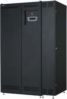
1 CALTECH Pasadena, CA Power Distribution Unit 225kVA PDU with (3) 42ckt Panel Distribution ILL OF MATERIAL ITEM 3 Eaton Powerware - Power Distribution Unit (PDU) Qty (3) - 225kVA Power Distribution Unit Each with: (3) 42Ckt Panel oard(ranch reakers by contractor) Input Voltage: Output Voltage: 480VAC, three phase, 3 wire plus ground, 60 Hertz 120/ VAC, three phase, 4 wire plus ground, 60 Hertz Each Module shall consist of the following: 1 - Main Input Circuit reaker (35kAIC) 1 - Input Line Arrestor 1 Level 2 LCD Digital Display Panel with System Monitoring 1-225kVA - K13 Transformer : 480 to 120/VAC, 3Ø, 4W 3-42-Circuit Panel oard each with 225A/3P Main C and with Top/ottom cable exit. 1 - SNMP/Modbus TCPIP Network Interface Card 1 - Emergency Power Off (EPO) 1 - Operation Manual 1 - Start Up and One Year Warranty (provided during normal hours-7x24) 1-18 Seismic Floor stand PDU Dimensions/Weight: 55.6"Wide x 32.0"Deep x 75"High NOTES 1. The above scope does not include offload, move or installation. Offload, move and installation is assumed to be provided by the installing electrical contractor or electrician. Equipment is shipped standard freight. It is assumed that contractor will offload and move into building. 2. Seismic anchoring is the responsibility of the contractor and not part of our scope. Anchoring attachments(angle brackets) are not included in this proposal or available by Eaton Powerware. Anchoring may require rear or side access. Seismic calculations can be added at additional cost. RAMTEK-Power Quality Solutions 1382 Valencia Ave, Unit M, Tustin, CA Phone: (949) , Fax: (949)
2 A AC INPUT MAIN INPUT REAKER C1 TRANSFORMER 480V/V OR 600V/V 225A PANELOARD NUMER 1 225A SUFEED REAKERS 225A PANELOARD NUMER 1 OUTPUT TO CRITICAL LOAD OUTPUT TO CRITICAL LOAD OUTPUT TO CRITICAL LOAD 225A PANELOARD NUMER 2 225A SUFEED REAKERS 225A PANELOARD NUMER 2 OUTPUT TO CRITICAL LOAD OUTPUT TO CRITICAL LOAD OUTPUT TO CRITICAL LOAD PDU SIDECAR (OPTIONAL) MAIN PDU PDU SIDECAR (OPTIONAL) OPTIONS MAIN PDU AVAILALE WITH OPTIONS FOR UP TO EIGHT 225A SUFEED REAKERS. SIDECARS AVAILALE WITH OPTIONS FOR ONE OR TWO 42-POLE 225A DISTRIUTION PANELS. SUFEED REAKER OUTPUT 480V INPUT AND /120V OUTPUT 600V INPUT AND /120V OUTPUT PDU ONELINE DRAWINGS A of6 EATON Powerware 225 kva PDU Installation and Operation Manual S Rev A-15
3
4
5 CT STRIP DISTRIUTION PANEL INPUT REAKER CT STRIP 225A SUFEED REAKERS (SEE SHEET 8 of 8 FOR DETAILS) 225A DISTRIUTION PANEL (USE CUTLER-HAMMER OLT-ON TYPE A OR QHW REAKERS, OR PLUG-ON TYPE HQP OR QPHW REAKERS.) AC INPUT (A,,C) (SEE SHEET 7 of 8 FOR DETAILS) OUTPUT GROUND TERMINALS NEUTRAL ONDING TERMINAL INPUT GROUND TERMINALS ISOLATED GROUND TERMINALS NEUTRAL TERMINALS MAIN PDU WITH LEFT SUFEED REAKERS AND ONE OUTPUT DISTRIUTION PANEL PDU POWER TERMINAL LOCATIONS of8 A-30 EATON Powerware 225 kva PDU Installation and Operation Manual S Rev
6 CT STRIP CT STRIP 225A DISTRIUTION PANEL (USE CUTLER-HAMMER OLT-ON TYPE A OR QHW REAKERS, OR PLUG-ON TYPE HQP OR QPHW REAKERS.) OUTPUT GROUND TERMINALS OUTPUT GROUND TERMINALS DISTRIUTION PANEL INPUT REAKER ISOLATED GROUND TERMINALS CT STRIP DISTRIUTION PANEL INPUT REAKER CT STRIP NEUTRAL TERMINALS NEUTRAL TERMINALS 225A DISTRIUTION PANEL (USE CUTLER-HAMMER OLT-ON TYPE A OR QHW REAKERS, OR PLUG-ON TYPE HQP OR QPHW REAKERS.) LEFT OR RIGHT FRONT FACING SIDECAR ONE OR TWO OUTPUT DISTRIUTION PANELS PDU POWER TERMINAL LOCATIONS of8 EATON Powerware 225 kva PDU Installation and Operation Manual S Rev A-33
7 PHASE C (5) AC INPUT TO MAIN REAKER C1 PHASE (3) PHASE A (1) INPUT MAIN REAKER C1 TERMINAL DETAIL PDU POWER TERMINAL LOCATIONS of8 EATON Powerware 225 kva PDU Installation and Operation Manual S Rev A-35
8 1. The PDU equipment operating environment must meet the weight requirements shown in Table A and size requirements shown on Drawing Table A. Equipment Weight Component Rating kva Weight Kgs (lbs) Shipping Installed Point Loading PDU (1045) 445 (980) 4 at (245) PDU (1195) 514 (1130) 4 at (282.5) PDU (1365) 591 (1300) 4 at (325) PDU (1690) 739 (1625) 4 at (406.3) PDU (1770) 775 (1705) 4 at (193.8) PDU (1890) 830 (1825) 4 at (456.3) PDU (2315) 1023 (2250) 4 at (562.5) PDU (2515) 1114 (2450) 4 at (612.5) PDU with single front facing Sidecar (1330) 570 (1255) 4 at (313.8) PDU with single front facing Sidecar (1480) 639 (1405) 4 at (351.3) PDU with single front facing Sidecar (1650) 716 (1575) 4 at 179 (393.8) PDU with single front facing Sidecar (1975) 864 (1900) 4 at 216 (475) PDU with single front facing Sidecar (2055) 900 (1980) 4 at 225 (495) PDU with single front facing Sidecar (2175) 955 (2100) 4 at (525) PDU with single front facing Sidecar (2600) 1148 (2525) 4 at 287 (631.3) PDU with single front facing Sidecar (2800) 1239 (2725) 4 at (681.3) PDU with single side facing Sidecar (1305) 559 (1230) 4 at (307.5) PDU with single side facing Sidecar (1455) 627 (1380) 4 at (345) PDU with single side facing Sidecar (1625) 705 (1550) 4 at (387.5) PDU with single side facing Sidecar (1950) 852 (1875) 4 at 213 (468.8) PDU with single side facing Sidecar (2030) 889 (1955) 4 at (488.8) PDU with single side facing Sidecar (2150) 943 (2075) 4 at (518.8) PDU with single side facing Sidecar (2575) 1136 (2500) 4 at 284 (625) PDU with single side facing Sidecar (2775) 1227 (2700) 4 at (675) PHYSICAL FEATURES AND REQUIREMENTS of2 EATON Powerware 225 kva PDU Installation and Operation Manual S Rev A-5
9 2. The PDU cabinet is palleted for shipping. 3. Donottiltcabinetsmorethan 10 during handling. 4. Dimensions are in millimeters and (inches). 5. The clearances required around the PDU cabinet are shown in Table and Drawing , starting on page A Table. PDU Cabinet Clearances From Top of Cabinet From Front of Cabinet From ack of Cabinet (main PDU, or main PDU withfrontfacingleftorrightsidecars) From ack of Cabinet (main PDU with side facing left and right sidecar) From Right Side of Cabinet (main PDU, main PDU with front facing left sidecar, or main PDU with side facing left sidecar) From Left Side of Cabinet (main PDU, main PDU with front facing left sidecar, or main PDU with side facing left sidecar) From Right Side of Cabinet (main PDU with front facing right sidecar or main PDU with front facing left and right sidecars) From Left Side of Cabinet (main PDU with front facing right sidecar, or main PDU with front facing left and right sidecars) From Right Side of Cabinet (main PDU with side facing right sidecar) From Left Side of Cabinet (main PDU with side facing left sidecar) From Left and Right Side of Cabinet (main PDU with side facing left and right sidecar) Minimum clearance over the PDU cabinet is millimeters (18 inches) for ventilation millimeters (36 inches) working space Minimum millimeters (4 inches) for ventilation 812 mm (32 inches) for door clearance and working space mm (16 inches) for door clearance and working space mm (19 inches) for door clearance and working space mm (19 inches) for door clearance and working space mm (19 inches) for door clearance and working space 812 mm (32 inches) for door clearance and working space 812 mm (32 inches) for door clearance and working space 812 mm (32 inches) for door clearance and working space PHYSICAL FEATURES AND REQUIREMENTS of A-6 EATON Powerware 225 kva PDU Installation and Operation Manual S Rev
10 6. The basic environmental requirements for operation of the PDU are: Ambient Temperature Range: C ( F) Recommended Operating Range: C ( F) Maximum Relative Humidity: 95%, noncondensing The PDU cooling requirements are shown in Table C through Table E. Table C. PDU Cooling Requirements During Full Load Operation without Transformer Rating Voltage Heat Rejection kva K-factor Input Output Watts TU/hr Kg-cal/hr 30 N/A N/A N/A N/A N/A N/A N/A N/A PHYSICAL FEATURES AND REQUIREMENTS of5 EATON Powerware 225 kva PDU Installation and Operation Manual S Rev A-7
11 Table D. PDU Cooling Requirements During Full Load Operation with 480V Transformer Rating Voltage Heat Rejection kva K-factor Input Output Watts TU/hr Kg --- cal/hr / / / / / / / / / / / / / / / / / / / / / / PHYSICAL FEATURES AND REQUIREMENTS of A-8 EATON Powerware 225 kva PDU Installation and Operation Manual S Rev
12 Table F. INPUT/OUTPUT Ratings and External Wiring Requirements for the Powerware 225 kva PDU Units Rating 60 Hz asic Unit Rating kva Input Output AC Input (3) Phases, (1) Neutral--- if required, (1) Ground Minimum Conductor Size Number per Phase A AC Output --- Volts Volts Maximum AMPS AWG or kcmil (each) Maximum AMPS Wiring should be sized in accordance with the PDU current rating, power cable termination sizes listed in Table J through Table L, and national and local electrical codes AC Output from Subfeed reaker to Critical Load (3) Phases, (1) Neutral, (1) Ground AC Output from Distribution Panel reakers to Critical Load Wire branch circuits in accordance with branch circuit breaker manufacturer s ratings, power cable termination sizes listed in Table M, and national and local electrical codes. Maximum output ratings are to be in accordance with the rating label on the PDU. The total combined load is not to exceed the maximum output rating. Wire branch circuits in accordance with branch circuit breaker manufacturer s ratings and instructions, and national and local electrical codes (output is prewired to the panelboard). Maximum output ratings are to be in accordance with the rating label on the PDU. The total combined load is not to exceed the maximum output rating. NOTE: Callout letters A and map to Drawing Table G. INPUT/OUTPUT Ratings & External Wiring Requirements for the Powerware PDU (480V) Units Rating 60 Hz asic Unit Rating kva Input Output AC Input (3) Phases, (1) Neutral--- if required, (1) Ground Minimum Conductor Size Number per Phase A AC Output --- Volts Volts Maximum AMPS AWG or kcmil (each) Maximum AMPS Wiring should be sized in accordance with the PDU current rating, power cable termination sizes listed in Table J through Table L, and national and local electrical codes AC Output from Subfeed reaker to Critical Load (3) Phases, (1) Neutral, (1) Ground AC Output from Distribution Panel reakers to Critical Load Wire branch circuits in accordance with branch circuit breaker manufacturer s ratings, power cable termination sizes listed in Table M, and national and local electrical codes. Maximum output ratings are to be in accordance with the rating label on the PDU. The total combined load is not to exceed the maximum output rating. Wire branch circuits in accordance with branch circuit breaker manufacturer s ratings and instructions, and national and local electrical codes (output is prewired to the panelboard). Maximum output ratings are to be in accordance with the rating label on the PDU. The total combined load is not to exceed the maximum output rating. NOTE: Callout letters A and map to Drawing POWER WIRING INSTALLATION NOTES of8 EATON Powerware 225 kva PDU Installation and Operation Manual S Rev A-17
13 Read and understand the following notes while planning and performing the installation: 1. Refer to national and local electrical codes for acceptable external wiring practices. 2. Material and labor for external wiring requirements are to be provided by designated personnel. 3. For external input wiring, use 90 C copper wire. See the appropriate column in Table F through Table H. Wire sizes are based on using the supplied breakers. 4. Wire ampacities are chosen from Table of the NEC. 5. Output neutrals are rated for 200%. 6. The PDU cabinet is shipped with a debris shield covering the ventilation grill on top of the unit. Do not remove the debris shield until installation is complete. However, remove the shield before operating the PDU. Once the debris shield is removed, do not place objects on the ventilation grill. 7. Optional 225A Distribution Panels use Cutler-Hammer bolt-on type A or QHW breakers for bolt-on panels, or plug-on type HQP or QPHW breakers for plug-on panels. reakers to be provided by the customer. 8. V input PDU is only available up to 150 kva. 480V and 600V input PDUs are available up to 225 kva. 9. K20 transformers are available up to 150 kva. 10. Refer to Section I of this manual for installation instructions. 11. If installing with a UPS, refer to the applicable UPS Installation and Operation manual for UPS cabinet wiring requirements, and conduit and terminal locations. 12. Per NEC article (a), all three-phase conductors must be run in the same conduit. Neutral and ground must be run in the same conduit as the phase conductors. 13. Conduit is to be sized to accommodate one neutral conductor the same size as the phase conductor and one ground conductor. If two neutral conductors or an oversized neutral conductor are to be installed, size the conduit to accommodate the extra wire or size. All PDU products can accommodate a double-sized neutral. POWER WIRING INSTALLATION NOTES of8 EATON Powerware 225 kva PDU Installation and Operation Manual S Rev A-19
14 14. See Table I for PDU input circuit breaker ratings. Table I. PDU Input Circuit reaker Ratings Main reaker kaic Rating Input Voltage kva Rating FLA Size Standard High A A A A A A A A A A A A A A A A A A A A A A POWER WIRING INSTALLATION NOTES of8 A-20 EATON Powerware 225 kva PDU Installation and Operation Manual S Rev
15 Table K. PDU INPUT Power Cable Terminations (480V) Terminal Function AC Input to Main reaker C1 Rating (kva) Main reaker Rating Terminal Function Size of Pressure Termination Tightening Torque Nm (lb in) Type Screw L1 Phase A #6 8 (75) Slotted 30 60A L2 Phase #6 8 (75) Slotted L3 Phase C #6 8 (75) Slotted N Neutral Not Required L1 Phase A #4 8 (75) Slotted 50 80A L2 Phase #4 8 (75) Slotted L3 Phase C #4 8 (75) Slotted N Neutral Not Required L1 Phase A # (120) 3/16 Hex A L2 Phase # (120) 3/16 Hex L3 Phase C # (120) 3/16 Hex N Neutral Not Required L1 Phase A / (120) 3/16 Hex A L2 Phase / (120) 3/16 Hex L3 Phase C / (120) 3/16 Hex N Neutral Not Required L1 Phase A / (120) 3/16 Hex A L2 Phase / (120) 3/16 Hex L3 Phase C / (120) 3/16 Hex N Neutral Not Required L1 Phase A / (120) 3/16 Hex A L2 Phase / (120) 3/16 Hex L3 Phase C / (120) 3/16 Hex N Neutral Not Required L1 Phase A /0 31 (275) 5/16 Hex A L2 Phase /0 31 (275) 5/16 Hex L3 Phase C /0 31 (275) 5/16 Hex N Neutral Not Required L1 Phase A /0 31 (275) 5/16 Hex A L2 Phase /0 31 (275) 5/16 Hex L3 Phase C /0 31 (275) 5/16 Hex N Neutral Not Required All All G Ground /0 31 (275) 5/16 Hex POWER WIRING INSTALLATION NOTES of A-22 EATON Powerware 225 kva PDU Installation and Operation Manual S Rev
16 Table M. PDU OUTPUT Power Cable Terminations reaker Size of Pressure Tightening Torque Type Terminal Function Rating Terminal Function Termination Nm (lb in) Screw 2 Phase A 1---4/0 31 (275) 5/16 Hex 4 Phase 1---4/0 31 (275) 5/16 Hex AC Output from 6 Phase C 1---4/0 31 (275) 5/16 Hex 225A Subfeed reaker ( F Frame) N Neutral 1---4/0 31 (275) 5/16 Hex to Critical Load #4---#6: 4.0 (35) 84 #4---#14 or G Ground #8: 2.8 (25) Slotted 2 x #12---#14 #10---#14: 2.3 (20) Wire branch circuits in accordance with branch circuit breaker manufacturers ratings and instructions and national and local electrical codes (output is prewired to the panelboard). AC Output from Distribution Panel reakers to Critical Load N G Neutral Ground 84 #4---#14 or 3 x #10---#14 84 #4---#14 or 2 x #12---#14 #4---#6: 4.0 (35) #8: 2.8 (25) #10---#14: 2.3 (20) #4---#6: 4.0 (35) #8: 2.8 (25) #10---#14: 2.3 (20) Slotted Slotted POWER WIRING INSTALLATION NOTES of8 A-24 EATON Powerware 225 kva PDU Installation and Operation Manual S Rev
17 1. Use Class 1 wiring methods (as defined by the NEC) for interface wiring up to 30V. The wire should be rated at 24V, 1A minimum. Use twisted pair wires for each input and common. All control wiring is customer-supplied. 2. Use Class 2 wiring methods (as defined by the NEC) for interface wiring from 30 to 600V. The wire should be rated at 600 volts, 1A minimum and 12 AWG maximum. Use twisted pair wires for each input and common. All control wiring is customer-supplied. 3. When installing external interface wiring (for example, building alarm, relay output, and X---Slot) to the PDU interface terminals, conduit must be installed between each device and the PDU cabinet. Install the interface wiring in separate conduit from the power wiring. 4. All building alarm inputs or remote features require an isolated normally-open contact or switch (rated at 24 Vdc, 20 ma minimum) connected between the alarm input and common terminal as shown. All control wiring and relay and switch contacts are customer-supplied. Use twisted-pair wires for each alarm input and common. 5. The building alarms can be programmed to display the alarm functional name using the front panel LCD display. 6. See Table N through Table P and Chapters 3, 4, and 9 for customer interface wiring. 7. LAN and telephone drops for use with X---Slot connectivity cards must be provided by facility planners or the customer. Table N. UC T1 and T2 Interface Connections Terminal T1 Name Description 1 uilding Alarm 1 2 uilding Alarm 1 Return Input: Programmable PDU alarms, activated by a remote dry 3 uilding Alarm 2 contact closure. 4 uilding Alarm 2 Return 5 Remote EPO NO Input: Normally-open dry contact to activate EPO of PDU 6 Remote EPO Return from a remote switch 7 Local EPO Input: Normally-open dry contact to activate EPO of PDU 8 Local EPO Return from local cabinet mounted EPO switch Terminal T2 Name Description 1 Alarm Relay Common 2 Alarm Relay NO 3 Alarm Relay NC Output: General purpose normally-open and normally-closed relay contacts. NOTE: RETURN INDICATES CONNECTION TO ELECTRONICS CIRCUIT GROUND; COMMON INDICATES CONNECTION TO COMMON SIDE OF ISOLATED RELAY CONTACT. INTERFACE WIRING INSTALLATION NOTES AND TERMINAL LOCATIONS of4 EATON Powerware 225 kva PDU Installation and Operation Manual S Rev A-37
18 INTERFACE TERMINAL LOCATIONS UC TERMINAL T1 (SEE SHEET 3of4 FOR DETAILS) TERMINAL T2 INTERFACE WIRING INSTALLATION NOTES AND TERMINAL LOCATIONS of4 A-38 EATON Powerware 225 kva PDU Installation and Operation Manual S Rev
19 INTERFACE TERMINALS UC UILDING ALARM 1 UILDING ALARM 1 RETURN UILDING ALARM 2 UILDING ALARM 2 RETURN REMOTE EPO NO REMOTE EPO RETURN LOCAL EPO LOCAL EPO RETURN ALARM RELAY COMMON ALARM RELAY NO ALARM RELAY NC NOTE: 1. All building alarm inputs require an isolated normally-open or normally-closed contact or switch (rated at 24 Vdc, 20 ma minimum) connected between the alarm input and common terminal as shown. uilding alarm inputs can be programmed for use with either normally-open or normally-closed contacts. All control wiring and relay and switch contacts are customer-supplied. 2. The building alarms can be programmed to display the alarm functional name using the front panel LCD display. INTERFACE WIRING INSTALLATION NOTES AND TERMINAL LOCATIONS of4 EATON Powerware 225 kva PDU Installation and Operation Manual S Rev A-39
20 8. TheRemoteEPOfeatureopensPDUcircuitbreakerC1andisolatespowerfromyour critical load. Local electrical codes may also require tripping upstream protective devices. 9. Remote EPO wiring should be a minimum of 22 AWG. 10. The REPO switch is provided by the customer and must be a dedicated latching-type switch not tied into any other circuits. TableO.RemoteEPO T1 4 5(NO) REMOTE EPO SWITCH TWISTED WIRES T1 5 6(RTN) PDU UC Remote EPO switch rating is 24 Vdc, 1A minimum. NOTE: This switch must be a dedicated normally open latchingtype switch not tied into any other circuits. Table P. Alarm Relay Contact T2 3 ALARM RELAY 1 2 CONTACT RATING Switched Voltage: 30 Vac 28 Vdc Maximum Current: 5A Minimum Wire Size: 22 AWG NOTE: Relay is shown in de-energized state. Relay changes state when the PDU is in normal mode. INTERFACE WIRING INSTALLATION NOTES AND TERMINAL LOCATIONS of4 A-40 EATON Powerware 225 kva PDU Installation and Operation Manual S Rev
21 Chapter 8 System Events 8.1 General When the PDU is operating, it continually monitors itself and the incoming utility power. System events on the PDU can be indicated by horns, lights, messages, or all three. Select Events from the menu bar on the Main Menu screen to look at the Active System Events screen. This screen shows any currently active alarms, notices, or commands. For more information on using the Events screen, see paragraph 7.2.2, Event Screens. 8.2 System Event Horns The system event horn beeps to alert an operator that an event needing attention is taking place. The Horn cycles at a half-second rate. 8.3 System Event Indicators The status indicators on the PDU control panel work with the event horn to let the operator know when the PDU is operating in any mode other than normal. Only the ON indicator is visible during normal PDU operation. The other indicators illuminate to indicate alarms or events. When an alarm occurs, you should first check these indicators to see what type of event has taken place. For descriptions of the status indicators, see paragraph 7.3, Reading the PDU Status Indicators. 8.4 System Event Messages When a system event occurs, a message appears on the LCD in the PDU status area. This message is also written to the Active Events log and may be added to the Events History log. The messages are divided into four categories: alarms, notices, status, and commands. The following tables contain the events displayed on the Events screen of the control panel. The default actions occurring for the events are listed. Some event actions are programmable. For more information contact your Eaton service representative. EATON Powerware PDU Installation and Operation Manual S Rev A 8-1
22 System Events ALARMS Message Horn Phone Relay Log* Indication uilding Alarm 2 No No Yes HA User Action Required uilding Alarm 2 OK No No Yes HA Condition Cleared Check Input Switchgear Yes Yes No HA Service Required Check Input Switchgear OK Off Yes No HA Condition Cleared L1 Overload Yes No No HA User Action Required L1 Overload OK Off No No HA Condition Cleared L1 Overload (High Level) Yes No No HA User Action Required L1 Overload (High Level) OK Off No No HA Condition Cleared L1 Overload (Extreme Level) Yes No No HA User Action Required L1 Overload (Extreme Level) OK Off No No HA Condition Cleared L2 Overload Yes No No HA User Action Required L2 Overload OK Off No No HA Condition Cleared L2 Overload (High Level) Yes No No HA User Action Required L2 Overload (High Level) OK Off No No HA Condition Cleared L2 Overload (Extreme Level) Yes No No HA User Action Required L2 Overload (Extreme Level) OK Off No No HA Condition Cleared L3 Overload Yes No No HA User Action Required L3 Overload OK Off No No HA Condition Cleared L3 Overload (High Level) Yes No No HA User Action Required L3 Overload (High Level) OK Off No No HA Condition Cleared L3 Overload (Extreme Level) Yes No No HA User Action Required L3 Overload (Extreme Level) OK Off No No HA Condition Cleared Output Overload Yes No No HA User Action Required Output Overload OK Off No No HA Condition Cleared Remote Emergency Power-off Yes No No A User Action Required Transformer Over Temperature Yes No Yes HA User Action Required Transformer Over Temperature OK Off No Yes HA Condition Cleared TVSS AAAAAAAAAAAAAAA No No Yes HA User Action Required TVSS AAAAAAAAAAAAAAA OK No No Yes HA Condition Cleared *Log codes indicate where the PDU records the event: H = History log; HA = History and Active logs; and A = Active log only. 8-2 EATON Powerware PDU Installation and Operation Manual S Rev A
23 System Events NOTICES Message Horn Phone Relay Log* Indication Check Modem Yes No No A Information Only Input AC Over Voltage No No No HA Information Only Input AC Over Voltage OK No No No HA Condition Cleared Input AC Under Voltage No No No HA Information Only Input AC Under Voltage OK No No No HA Condition Cleared Input Phase Rotation Error No No No No Information Only Input Under or Over Frequency No No No HA Information Only Input Under or Over Frequency OK No No No HA Condition Cleared Modem Call Completion Failed No No No A Information Only Checksum Failure No No No No Information Only Output AC Over Voltage No No No HA Information Only Output AC Over Voltage OK No No No HA Condition Cleared Output AC Under Voltage No No No HA Information Only Output AC Under Voltage OK No No No HA Condition Cleared OutputUnderorOverFrequency No No No HA Information Only Output Under or Over Frequency OK No No No HA Condition Cleared Site Wiring Fault No No No No Information Only *Log codes indicate where the PDU records the event: H = History log; HA = History and Active logs; and A = Active log only. EATON Powerware PDU Installation and Operation Manual S Rev A 8-3
24 System Events STATUS Message Horn Phone Relay Log* Indication Incoming Modem Call Started No No No A User Status Modem Call Completed Successfully No No No A User Status Modem Connection Established No No No A User Status Outgoing Modem Call Started No No No A User Status *Log codes indicate where the PDU records the event: H = History log; HA = History and Active logs; and A = Active log only. COMMAND Message Horn Phone Relay Log* Indication Emergency Shutdown No No No No Information Only *Log codes indicate where the PDU records the event: H = History log; HA = History and Active logs; and A = Active log only. 8-4 EATON Powerware PDU Installation and Operation Manual S Rev A
25 SEMPRA Monterey Park EATON POWERWARE POWER DISTIRUTION UNIT(PDU) Level 2 Commumication and Monitoring : Energy Management System (EMS) EMS Level 2 The energy management system will provide microprocessor based monitoring and control for the PDU. Information will be displayed on a local 8 X 40 backlight LCD panel located on the front of the PDU accessible without opening the door. The LCD panel shall have 4 indicators for On, Off, Overload and Alarm. A Horn shall be integral to the system. The LCD panel shall have 5 key switches for menu navigation for monitoring, control and setup functions. The system shall be capable to monitor two (2) three phase voltage/current ports and up to 336 additional branch circuit feeds. The energy management system shall have event log capability for Alarm, Notice Status and Command events. Data shall be displayed on an LCD panel and have capability to be transmitted serially to communications devices such as WebServers, Modems and RS232 ports via Web/SNMP or Modbus TCP/IP protocols including Powerware s centralized monitoring system utilizing X-slot technology. Analog and digital signals shall be processed by the controller generating metering, alarm, statistical and status information. The system shall drive 5 programmable output relays and two serial ports and also provide two discrete inputs for programmable building alarms. All currents and voltages shall be monitored using true RMS measurements. The energy management system shall come fully calibrated from the factory. This specification strictly forbids field calibration requirements. Level 2 provides system level input and output meters, active events and history log, setup menu, mimic screen and advanced system features such as programmable building alarms, profile log and X-Slot capability. Display Information shall be displayed on a local 8 X 40 backlight LCD panel located on the front of the PDU accessible without opening the door. The LCD panel shall have 4 indicators for On, Off, Overload and Alarm. A Horn shall be integral to the system. The LCD panel shall have 5 push buttons for menu navigation for monitoring, configuration and control functions. Four LEDs located on the LCD panel shall indicate the following: GREEN: Illuminates when the output is energized
26 YELLOW: Illuminates if output current of any phase exceeds its 100% current level YELLOW: RED: alarms Illuminates when the output is de-energized. When EPO reset is required, the LED will flash at a one second rate. Will flash any time an active Alarm is present on the active screen. Monitored Parameters The energy management system shall monitor and display the following parameters: Input Voltage (VL-L) Input Current (A, & C phase) Input Voltage THD for all three phases Input Frequency Output Voltage (VL-L and VL-N) Output Current (A, & C phase) Output Neutral Current Output Current %(A, & C phase) Output Voltage Total Harmonic Distortion (THD) for all three phases Output Current Total Harmonic Distortion (THD) for all three phases Output Current Crest Factor System Ground Current Output Frequency Output Power Factor (Lead/Lag Indicator) Output kva Output kw Output KWH Monthly KW HR Yearly KW HR Total KW HR Date Time
27 Alarms Alarms shall be classified as Notice or Alarm. A Notice is a minor Alarm that does not activate the horn. Upon receiving an alarm, the energy management system shall activate a horn, red LED and Form-C Summary Alarm Relay. The alarm or notice event shall be displayed on the active events screen and also be available through serial communication devices. The system shall be configurable to make an outgoing service call. A soft key on the LCD panel shall be used to SILENCE the horn and reset the relay and LED alarm indicator. Alarms shall be categorized by the system as User Alarm, Shutdown is imminent, Service Required, Schedule Service or Service Alarm. Notices shall be categorized as Information Only, User Interaction Required and User Investigation. Remote monitoring shall include notification of critical alarms, a monthly report summarizing alarms and important data relevant to PDU or system performance. All alarm thresholds (factory set points shown in brackets) shall be adjustable by way of the service port to meet site requirements. The system shall detect and alarm the following conditions: Input AC Undervoltage (90% of nominal) Input AC Overvoltage (110% of nominal) Input Under / Over Frequency (+/- 3Hz of nominal) Input Phase Rotation Error Remote Emergency Power Off Emergency Shutdown Command Transformer Over-Temperature Warning (180 0 C) Transformer Over-Temperature Shutdown (200 0 C) Output AC Undervoltage (90% of nominal) Output AC Overvoltage (110% of nominal) Output Overload Overload Warning for all three phases (Level 1) - 100% Overload for all three phases (Level 2) - 110% Large Overload for all three phases (Level 3) - 125% Output Under / Over Frequency (+/- 0.5Hz of nominal) Output Phase Rotation Error Input Voltage THD Warning for all three phases Input Current THD Warning for all three phases Output Voltage THD Warning for all three phases
28 Output Current THD Warning for all three phases Summary Notice Summary Alarm EEPROM Fault Internal Communication Fault Configuration Error Profile Log Profile Log feature provides the maximum and minimum deviations for the month. The exact time that the deviation occurred is also recorded. Data is sampled every five milliseconds. The profile data is recorded in non-volatile memory each hour. The meter shall have the ability to store and view up to twenty-four (24) monthly readings per parameter: a. Output Voltage (All three phases independently) b. Output Current (All three phases independently) c. Output Frequency d. Output Voltage THD (All three phases independently) e. Output Current THD (All three phases independently) f. Output Current Crest Factor for all three phases g. Output KW h. Output KVA i. Output Power Factor j. Input Voltage (All three phases independently) k. Input Current (All three phases independently) l. Input Frequency m. Input Voltage THD (All three phases independently) n. Input Power Factor o. Input kw p. Input kva q. Ground Current r. Output Neutral Current Programmable uilding Alarms The EMS shall be capable of providing annunciation for two customizable building alarm inputs (N/O or N/C dry contacts). The action associated with the alarms is user configurable for Alarm only or Alarm and shunt trip. The associated customized message can be up to 20 characters long and entered either via the LCD panel or RS232 service port.
29 Control The PDU shall be capable of a shutdown on the following alarms: Phase Rotation Phase Loss Ground Fault uilding Alarms Transformer Over Temperature Communication The EMS level 2 system must be capable of communicating via hot pluggable X- slot cards. Remote monitoring shall include notification of critical alarms, a monthly report summarizing alarms and important data relative to the PDU or system performance. Supported cards: Power Xpert Gateway X-Slot Card providing SNMP, Modbus TCP, and Environmental Monitoring Probe functionality. Modbus Card (RS232/485) providing a limited set of system meters and alarms.
30

31
32
UltraLITE Model ELU Centralized Emergency Lighting Inverter 4.2 KW- 5 KW
 12/23/16 Rev 9 UltraLITE Model ELU General Specification 4.2 KW to 5 KW UltraLITE Model ELU Centralized Emergency Lighting Inverter 4.2 KW- 5 KW 1.0 General General Specification This specification describes
Liebert PPC Second Generation Power Distribution Cabinet
 Liebert PPC Second Generation Power Distribution Cabinet Emerson Network Power Delivers The Packaged Power Solution Creating high quality power is a major step towards protecting the operation of a critical
Spectron LSN (Life Safety Network) Suggested Specifications
 Suggested Specifications") 1. General 1.1 Scope A Dual-Lite Spectron LSN (Life Safety Network) Series Inverter System shall be furnished to provide a reliable source of power, and shall operate during a utility line deficiency without
1. General 1.1 Scope A Dual-Lite Spectron LSN (Life Safety Network) Series Inverter System shall be furnished to provide a reliable source of power, and shall operate during a utility line deficiency without
LiteMinder. LM Series Inverter Pure Sine Wave Modular Inverter Technology. Fast Transfer System 1.0 to 18.75KVA LED Compatible
 LiteMinder Fast Transfer System 1.0 to 18.75KVA LED Compatible Series Pure Sine Wave Modular Technology Modular AC System Evenlite s LiteMinder Central System provides an innovative Emergency Lighting
LORAIN CIP 4890/48120 DC Power System
 DC Power for Business-Critical Continuity Key Features Compact flexibility provides rectifiers, distribution, and controller in one shelf Constant power delivers more current at lower voltages to meet
Liebert LDMF Distribution Monitoring. User Manual
 Liebert LDMF Distribution Monitoring User Manual TABLE OF CONTENTS IMPORTANT SAFETY INSTRUCTIONS................................................1 1.0 GLOSSARY OF ABBREVIATIONS.............................................2
PowerWave 2 Busway System
 PowerWave 2 Busway System Guide Specifications (Revision 004, 11/17/2017) 1 GENERAL 1.1 Summary This specification covers the electrical characteristics and general requirements for a continuous opening,
TT /97. Features INSTALLATION INSTRUCTIONS. Horn. Lamps
 TT-1023 1/97 INSTALLATION INSTRUCTIONS Original Issue Date: 2/94 Model: 6-2000 kw Market: Industrial Subject: Flush- or Surface-Mount Remote Annunciator Kits PA-293991 and PA-293991-SD The remote annunciator
elite Model ELN Centralized Emergency Lighting Inverter Systems 550 W to 1.5 KW Systems
 5/25/16 rev 6 elite Model ELN General Specification 550 W to 1.5 KW elite Model ELN Centralized Emergency Lighting Inverter Systems 550 W to 1.5 KW Systems 1.0 General General Specification This specification
MASTER JOCKEY PUMP CONTROLLER. Model JPCE INSTRUCTION MANUAL. C 2018 Master Control Systems, Inc
 MASTER JOCKEY PUMP CONTROLLER Model JPCE INSTRUCTION MANUAL C 2018 Master Control Systems, Inc TABLE OF CONTENTS Important Safety Information. Page 3 General Description and Installation.. Page 4 Model
ILLUMINATOR EM. CENTRAL LIGHTING INVERTER 1000 VA/W through 2800 VA/W 98% Efficiency!
 ILLUMINATOR EM CENTRAL LIGHTING INVERTER 1000 VA/W through 2800 VA/W 98% Efficiency! THE ILLUMINATOR SERIES EM The Illuminator Series EM is a fast transfer Emergency Lighting Inverter utilizing Myers Power
CONTROL PANEL INTERFACE ACTIVATE THE GENERATOR DISPLAY INTERFACE MENUS. Control Panel USING THE AUTO/OFF/MANUAL SWITCH
 CONTROL PANEL INTERFACE USING THE AUTO/OFF/MANUAL SWITCH With the switch set to AUTO, the engine may crank and start at any time without warning. Such automatic starting occurs when utility power source
LEAKMONITOR MULTIZONE WATER LEAK DETECTION ALARM PANEL INSTALLATION AND USER OPERATION MANUAL
 LEAKMONITOR MULTIZONE WATER LEAK DETECTION ALARM PANEL INSTALLATION AND USER OPERATION MANUAL The LeakMonitor alarm panel is a microprocessor controlled fully adjustable alarm system suitable for multizone
DGC-1000 DIGITAL GENSET CONTROLLER
 DGC-1000 DIGITAL GENSET CONTROLLER Basler Electric s Digital Genset Controller (DGC-1000) offers a low cost microprocessor based integrated alternative for small to medium sized genset control and monitoring.
MASTER PRESSRE MAINTANENCE CONTROLLER. Models PMCE INSTRUCTION MANUAL. C 2018 Master Control Systems, Inc
 MASTER PRESSRE MAINTANENCE CONTROLLER Models PMCE INSTRUCTION MANUAL C 2018 Master Control Systems, Inc TABLE OF CONTENTS Important Safety Information. Page 3 General Description and Installation.. Page
LORAIN CSP DC Power System
 DC Power for Business-Critical Continuity Key Features Compact flexibility provides more space for revenue generating equipment Constant power delivers more current at lower voltages to meet load or recharge
La Marche Manufacturing Company Option 46 Series. Digital Combined Accessory Package. Installation and Operation Manual
 La Marche Manufacturing Company www.lamarchemfg.com Option 46 Series Digital Combined Accessory Package Installation and Operation Manual This manual is subject to change without notice. You may obtain
ILLUMINATOR E & IE CENTRAL INVERTER FOR EMERGENCY LIGHTING
 ILLUMINATOR E & IE CENTRAL INVERTER FOR EMERGENCY LIGHTING THE ILLUMINATOR ILLUMINATOR SERIES IE The Illuminator Series IE is an interruptible lighting inverter. It transfers to inverter mode (battery
920 Series. A dry contact relay is provided for alarm annunciation back to a distributed control system (DCS).
.") Product overview The DigiTrace 920 is a compact, full-featured, microprocessor-based, multipoint heat-trace controller. The 920 provides control and monitoring of two independent electrical heat-tracing
Product overview The DigiTrace 920 is a compact, full-featured, microprocessor-based, multipoint heat-trace controller. The 920 provides control and monitoring of two independent electrical heat-tracing
TYPE CM-2201 NELSON SINGLE POINT CIRCUIT MANAGEMENT SYSTEM
 2 Line, 16 Characters/row LCD Display Temperature Input Range -50 C to +500 C -58 F to + 932 F Enclosure NEMA Type 4X Current Rating 30A max (resistive load only) Ambient Temperature -40 C to + 40 C -40
PowerLogic Branch Circuit Power Meter (BCPM)
") PowerLogic Branch Circuit Power Meter (BCPM) Panel Board Monitoring System Installation Guide Branch Circuit Power Meter (BCPM) HAZARD CATEGORIES AND SPECIAL SYMBOLS Read these instructions carefully and
PowerLogic Branch Circuit Power Meter (BCPM) Panel Board Monitoring System Installation Guide Branch Circuit Power Meter (BCPM) HAZARD CATEGORIES AND SPECIAL SYMBOLS Read these instructions carefully and
Across-the-Line SERIES MP300 Combined Manual and Automatic
 Across-the-Line SERIES MP300 Combined Manual and Automatic Metron Fire Pump Controllers conform to the latest requirements of National Fire Protection Association s Standard for Centrifugal Fire Pumps
Beacon 200 Gas Monitor Operator s Manual. Part Number: RK Released: 6/6/08
 Beacon 200 Gas Monitor Operator s Manual Part Number: 71-2102RK Released: 6/6/08 Table of Contents Chapter 1: Introduction.................................................3 Overview.............................................................3
INSTALLATION INSTRUCTIONS
 TT-1343 5/06b INSTALLATION INSTRUCTIONS Original Issue Date: 8/03 Model: Automatic Transfer Switches Equipped with Series 1000 Programmable Controller Market: ATS Subject: Remote Annunciator Kits GM28938-KP1,
Soft Start Series MP700 Solid State, Reduced Voltage
 Metron Fire Pump Controls and Accessories Soft Start Series MP700 Solid State, Reduced Voltage Metron Fire Pump Controllers conform to the latest requirements of National Fire Protection Association s
CHAPTER 20 SERVICE EQUIPMENT
 SERVICE EQUIPMENT CHAPTER 20 SERVICE EQUIPMENT Service equipment includes service cabinets and the equipment and materials necessary for installation. 20.1 Signal Service Cabinet For MnDOT traffic control
ILLUMINATOR E & IE CENTRAL INVERTER FOR EMERGENCY LIGHTING
 ILLUMINATOR E & IE CENTRAL INVERTER FOR EMERGENCY LIGHTING ALSO AVAILABLE FROM MYERS POWER PRODUCTS: ILLUMINATOR SERIES CIII 4.8 kva TO 50 kva THREE PHASE ILLUMINATOR CM 500 VA TO 2000 VA SINGLE PHASE
CARD ACCESS CONTROL SYSTEM
 SECTION 13851 CARD ACCESS CONTROL SYSTEM PART 1 GENERAL 1.01 SUMMARY A. Section Includes: A complete, operable, tested, integrated proximity access control system, to operate on a proximity principle where
21-light Remote Annunciator. Owner s Manual
 21-light Remote Annunciator Owner s Manual Annunciator Description... Inside Font Cover Detailed Specifications... 1 Environmental Specifications... 1 Power Supply Requirements... 1 Communication With
Rev Pulse Modulating Anti- Sweat Control (PMAC II) Installation and Operation Manual
 Installation and Operation Manual") 026-1501 Rev 5 3-20-03 Pulse Modulating Anti- Sweat Control (PMAC II) Installation and Operation Manual 1640 Airport Road, Suite 104 Kennesaw, GA 31044 Phone: (770) 425-2724 Fax: (770) 425-9319 ALL RIGHTS
026-1501 Rev 5 3-20-03 Pulse Modulating Anti- Sweat Control (PMAC II) Installation and Operation Manual 1640 Airport Road, Suite 104 Kennesaw, GA 31044 Phone: (770) 425-2724 Fax: (770) 425-9319 ALL RIGHTS
SLATE. Base Module INSTALLATION INSTRUCTIONS R8001A1001
 SLATE Base Module R8001A1001 INSTALLATION INSTRUCTIONS Scan for more information Application SLATE brings configurable safety and programmable logic together into one single platform. The platform can
Models NFPA 1221-A, NFPA 1221-B Public Safety DAS Annunciator Panel. Revision E 61117
 Models NFPA 1221-A, NFPA 1221-B Public Safety DAS Annunciator Panel Revision E 61117 CAUTION: (Read This First) This panel has been designed to make it nearly bullet proof to mistakes made when wiring
T M. User Manual. MarinaGuard. Ground Fault Monitoring Panel For Marina Shore Power
 T M User Manual MarinaGuard Ground Fault Monitoring Panel For Marina Shore Power NAE1095810 / 03.2013 T M Bender Inc. USA: 700 Fox Chase Coatesville, PA 19320 Toll-Free: 800-356-4266 Phone: 610-383-9200
SECTION PANELBOARDS. A. Drawings and general provisions of the Contract, including General and Supplementary Conditions, apply to this Section.
 PART 1 - GENERAL 1.1 RELATED DOCUMENTS A. Drawings and general provisions of the Contract, including General and Supplementary Conditions, apply to this Section. 1.2 SUMMARY A. This Section includes the
Product Data Sheet. Remote Terminals. Features:
 Remote Terminals Product Data Sheet Features: Based around two core products, the Mx- 4010 Remote Display Terminal (RDT) and the fully functional Mx-4020 Remote Control Terminal (RCT). Both remote terminals
20 Light Remote Annunciator
 Light Remote Annunciator Owner s Manual Surface Mount Flush Mount 94-95- Standard Annunciator 94-, 94-95-, 95-4- 4- Annunciator w/remote Relay Panel 4-, 4-4-, 4-49-, 49-49-, 49- Time Multiplexed Annunciator
910 Series Single-point heat-tracing control system
 Single-point heat-tracing control system 910*E1FWL*SSR2 Product overview The Raychem 910 is a compact, full-featured, microprocessor-based, single-point heat-tracing control system. The 910 provides control
Galaxy Pulsar Plus Digital Battery Plant Controller
 Galaxy Pulsar Plus Digital Battery Plant Controller Features Supports up to 60 Power Modules rectifiers and converters Supports dual voltage plants, with rectifiers and converters Auto-sensing dual voltage
Variable Frequency Drive SERIES MP800 VFD
 Metron Fire Pump Controls and Accessories Variable Frequency Drive SERIES MP800 VFD Metron Fire Pump Controllers conform to the latest requirements of National Fire Protection Association s Standard for
Power Management Module-c (PMM-c)
") Power Management Module-c (PMM-c) 60 160 kva Installation, Operation and Maintenance 11/2013 www.schneider-electric.com Legal Information The Schneider Electric brand and any registered trademarks of Schneider
Power Management Module-c (PMM-c) 60 160 kva Installation, Operation and Maintenance 11/2013 www.schneider-electric.com Legal Information The Schneider Electric brand and any registered trademarks of Schneider
PowerWizard. Level 1.0 & Level 2.0 Control Systems Training
 PowerWizard Level 1.0 & Level 2.0 Control Systems Training New Systems Current Systems Systems Comparison Level 1 Level 2 Level 3 Level 4 PowerWizard Level 3.0 PowerWizard Level 4.0 Overview Common parts
ESP TECHNOLOGIES LIMITED
 Alarm Technology ESPAN-01 Series Annunciator System Combination type User Manual (Rev. 1) ESP TECHNOLOGIES LIMITED www.esptechno.com Content Page Introduction 2 General Description 2 Overview - Annunciator
Pioneer-R16 Gas Monitor Operator s Manual
 Pioneer-R16 Gas Monitor Operator s Manual Edition 7/2/97 RKI INSTRUMENTS, INC RKI Instruments, Inc. 33248 Central Ave, Union City, CA 94587 (510) 441-5656 Chapter 1: Description About the Pioneer-R16 Gas
C SINGLE-POINT HEAT-TRACING CONTROL SYSTEM PRODUCT OVERVIEW
 SINGLE-POINT HEAT-TRACING CONTROL SYSTEM PRODUCT OVERVIEW SHIFT TEST SHIFT C910 SERIES ALARM MONITOR CONFIG BACK ENTER PROGRAMMABLE SINGLE POINT HEAT-TRACING CONTROLLER HEAT-TRACING CONTROLLER STATUS ALARM
PowerLogic ION Setup Meter Configuration Software Configuration Guide
 PowerLogic ION Setup Meter Configuration Software Configuration Guide 70002-0293-03 12/2010 Conventions Used in this Manual This section describes the symbols and terminology used in this guide. Symbols
OPTICAL TURNSTILE SYSTEM
 OPTICAL TURNSTILE SYSTEM Installation Instructions OTS-WNG UNPACK TURNSTILES. Remove the bolts at the ends of the turnstiles to separate from the skids and place turnstiles on the floor. With a box knife
INSTRUCTION MANUAL and DETAILED PRODUCT SPECIFICATION TRIPLEX PUMP CONTROL SYSTEM MODEL NUMBER CPC-3. M336 Rev F. November 21, 2000.
 INSTRUCTION MANUAL and DETAILED PRODUCT SPECIFICATION TRIPLEX PUMP CONTROL SYSTEM MODEL NUMBER CPC-3 M336 Rev F November 21, 2000 ÇConsilium Consilium US, Inc. 59 Porter Rd Littleton, MA 01460-1431 USA
Powerohm Resistors Digital HRG System
 Installation and Operating Instructions Powerohm Resistors Digital HRG System This manual provides general information, installation, operation, maintenance, and system setup information for the Powerohm
Student Services & Classroom Addition. A. Section includes distribution panelboards and lighting and appliance branch-circuit panelboards.
 SECTION 262416 - PANELBOARDS PART 1 - GENERAL 1.1 SUMMARY A. Section includes distribution panelboards and lighting and appliance branch-circuit panelboards. 1.2 PERFORMANCE REQUIREMENTS A. Seismic Performance:
Flostop TS D7E and A8E. Operation Manual
 Flostop TS D7E and A8E Operation Manual United Kingdom Spectron Gas Control Systems Ltd, Unit 4, ATU1, University of Warwick science Park, Coventry, +44 (0) 24 7641 6234 sales@spectron-gcs.com Germany
DGC-500 DIGITAL GENSET CONTROLLER
 DGC-500 DIGITAL GENSET CONTROLLER Basler Electric s Digital Genset Controller (DGC-500) offers a low cost microprocessor based integrated alternative for the control and monitoring of small to medium sized
Carbon Monoxide Transmitter
 Introduction The CO Transmitter uses an electrochemical sensor to monitor the carbon monoxide level and outputs a field-selectable 4-20 ma or voltage signal. The voltage signal may also be set to 0-5 or
Two-Channel Gas Controller
 Two-Channel Gas Controller Specifications subject to change without notice. USA 09 Page of DESCRIPTION Highly configurable, UL 0 performance-tested and -certified, and wall-mounted gas monitor; continuously
A. Section includes distribution panelboards and lighting and appliance branch-circuit panelboards.
 SECTION 262416 - PANELBOARDS PART 1 - GENERAL 1.1 SUMMARY A. Section includes distribution panelboards and lighting and appliance branch-circuit panelboards. 1.2 PERFORMANCE REQUIREMENTS A. Seismic Performance:
ITC 2000 HEATING CONTROL CABINET. Installation & Operation Manual
 ITC 2000 HEATING CONTROL CABINET Installation & Operation Manual VTI, Incorporated 24 McMillan Way Newark, DE 19713 Phone (302) 738 0500 FAX (302) 738 6594 Revision Level 0.03 Manual No. 90003314 June,
TTSIM-1A. TraceTek Sensor Interface Module with Relay. Installation/Operation Instructions. Installation Items (not supplied) Tools Required.
 Tools Required.") TTSIM-1A TraceTek Sensor Interface Module with Relay Installation Items (not supplied) General Information Installation/Operation Instructions Please read these instructions and keep them in a safe place.
TTSIM-1A TraceTek Sensor Interface Module with Relay Installation Items (not supplied) General Information Installation/Operation Instructions Please read these instructions and keep them in a safe place.
TraceNet ECM Series Control System
 TraceNet ECM Series Control System ECM Operating Guide Thermon Manufacturing Company TraceNet is a registered trademark of Thermon Manufacturing Company. ECM Operating Guide 2014, 2015 Thermon Manufacturing
Operating & Maintenance Manual. Alert-4 Ethernet LCD Master Alarm
 Operating & Maintenance Manual Alert-4 Ethernet LCD Master Alarm w w w. a m i c o. c o m Contents User Responsibility 4 Introduction 4 Features 5 Description of the Alarm 5 Shipment Details 5 The Alarm
Multi-Gas-Controller MGC2
 Page 1 Aug. 2018 Gas measuring, monitoring and warning controller based on state-of-the-art micro-technology for continuous monitoring of the ambient air to detect toxic and combustible gases, refrigerants
C SINGLE-POINT HEAT-TRACING CONTROL SYSTEM. product overview
 C910-485 SINGLE-POINT HEAT-TRACING CONTROL SYSTEM product overview ALARM SHIFT TEST C910 SERIES MONITOR CONFIG BACK ENTER PROGRAMMABLE SINGLE POINT HEAT-TRACING CONTROLLER STATUS ALARM OUTPUT The DigiTrace
Tachometer/Hourmeter/Trip. Installation and Operation Manual
 3211 Fruitland Ave Los Angeles, CA 90058 MTH-103E Tachometer/Hourmeter/Trip Installation and Operation Manual Rev. G P/N 145F-13048 PCO - 00010525 Copyright 2014-2017, Barksdale Inc. All Rights Reserved
DIGITAL METERS Large Display Temperature Meters Instruction Manual
 DIGITAL METERS Large Display Temperature Meters PD755 PD756 PD757 Handles Thermocouple & RTD Inputs with Simplicity J, K, T, E, R, & S Thermocouples 100 Ω Platinum RTD (0.00385 or 0.00392 curve) Large
Dual-point heat-tracing control system
 Dual-point heat-tracing control system 920*E4FWL*SIS302*SS3102 shown Product overview The Raychem 920 is a compact, full-featured, microprocessor-based, dual-point heat-tracing control system. The 920
Beacon 410A Gas Monitor Operator s Manual
 Beacon 410A Gas Monitor Operator s Manual Part Number: 71-0397 Revision: F Released: 12/5/17 www.rkiinstruments.com Product Warranty RKI Instruments, Inc., warrants gas alarm equipment sold by us to be
FlameGard 5 MSIR HART
 FlameGard 5 MSIR HART Multi-Spectral Infrared Flame Detector HART Communication with the FlameGard 5 Multi-spectral Infrared Detector The information and technical data disclosed in this document may be
GasScanner 4C. Four Channel Monitor. Operator s Manual. MINT-0280-XX Rev. A 02/25/08
 GasScanner 4C Four Channel Monitor Operator s Manual MINT-0280-XX Rev. A 02/25/08 Product Warranty Matheson Tri-Gas., warrants gas alarm equipment sold by us to be free from defects in materials, workmanship,
1.1 Ethernet Remote Annunciator Controller (RAC) using the up to 4 ATC-300+ connected via RS-485 to TCP/IP gateway
 using the up to 4 ATC-300+ connected via RS-485 to TCP/IP gateway") Ethernet Remote Annunciator Controller (RAC) Instruction Sheet for Automatic Transfer Switches (4 x ATS) Revision: 01 IB01602082E 1.1 Ethernet Remote Annunciator Controller (RAC) using the up to 4 ATC-300+
Ethernet Remote Annunciator Controller (RAC) Instruction Sheet for Automatic Transfer Switches (4 x ATS) Revision: 01 IB01602082E 1.1 Ethernet Remote Annunciator Controller (RAC) using the up to 4 ATC-300+
DIESEL Engine Fire Pump Controllers Features
 September 007 DIESEL Engine Fire Pump Controllers Features FD0 Diesel Engine Controllers 1-1 Printer / Recorder The industrial grade thermal printer is housed in a rugged steel enclosure within the controller.
NGC-40 Advanced Heat-Tracing Control System
 NGC-40 Advanced Heat-Tracing Control System Local configuration and monitoring with Raychem Touch 1500 touch screen display Heat-tracing system NGC-40 system Remote configuration and monitoring with Raychem
LMR Electric Fire Pump Controllers Features
 1-1 Printer / Recorder The industrial grade thermal printer is housed in a rugged steel enclosure within the controller. The on/off switch, feed and reset buttons are front accessible. A bi-color status
Flopurge TS. Operation Manual
 Flopurge TS Operation Manual Part Number 079-0204 Spectron Gas Control Systems United Kingdom Unit 4, Herald Court, University of Warwick Science Park, Coventry, CV4 7EZ +44 (0)24 7641 6234 sales@spectron-gcs.com
Oxygen (O2) Single-Point Gas Detection System
 Single-Point Gas Detection System") Oxygen (O) Single-Point Gas Detection System DESCRIPTION Wall-mounted gas monitor with built-in oxygen (O) sensor, accepts one analog remote device such as a secondary gas sensor, temperature or humidity
Oxygen (O) Single-Point Gas Detection System DESCRIPTION Wall-mounted gas monitor with built-in oxygen (O) sensor, accepts one analog remote device such as a secondary gas sensor, temperature or humidity
Beacon 110 Gas Monitor Operator s Manual
 Beacon 110 Gas Monitor Operator s Manual Part Number: 71-0110RK Revision: H Released: 12/5/17 RKI Instruments, Inc. www.rkiinstruments.com Product Warranty RKI Instruments, Inc., warrants gas alarm equipment
ModSync Sequencing System Installation & Operation Manual. For use with Fulton Steam Boilers.
 ModSync Sequencing System Installation & Operation Manual For use with Fulton Steam Boilers. Revision 3.0 8/21/2008 - 2 - Table of Contents Introduction Page 4 Features Page 4 Sequence of Operation Page
MODEL FPT-130 SINGLE POINT FREEZE PROTECTION HEAT TRACE CONTROL
 TRACON MODEL FPT-130 SINGLE POINT FREEZE PROTECTION HEAT TRACE CONTROL TABLE OF CONTENTS FPT 130 Overview... 2 Installation... 3 Power Source and Load Connections... 4 Temperature Sensor... 5 External
Controllers. Instruction Manual WARNING
 Controllers Instruction Manual WARNING THIS MANUAL MUST BE CAREFULLY READ BY ALL INDIVIDUALS WHO HAVE OR WILL HAVE THE RESPONSIBILITY FOR INSTALLING, USING OR SERVICING THIS PRODUCT. Like any piece of
Nitrogen Dioxide (NO2) Single-Point Gas Detection System
 Single-Point Gas Detection System") Nitrogen Dioxide (NO) Single-Point Gas Detection System DESCRIPTION Wall-mounted gas monitor with built-in nitrogen dioxide (NO)/diesel fume gas sensor, accepts one analog remote device such as a secondary
Nitrogen Dioxide (NO) Single-Point Gas Detection System DESCRIPTION Wall-mounted gas monitor with built-in nitrogen dioxide (NO)/diesel fume gas sensor, accepts one analog remote device such as a secondary
ACS-30 MULTIPOINT COMMERCIAL HEAT-TRACING SYSTEM PRODUCT OVERVIEW. ACS-30 System
 SHIFT TEST BACK ENTER C910 SERIES STATUS OUTPUT ACS-30 MULTIPOINT COMMERCIAL HEAT-TRACING SYSTEM ACS-30 System MONITOR CONFIG POWER CONTROL MODULE ACCS-PCM-5 PROGRAMMABLE SINGLE POINT HEAT-TRACING CONTROLLER
D8024, D9024, D10024 Analog Fire Alarm Control Panels Programming Guide
 System Reset Trou ble Silence Ala rm Silence Manual Ala rm ENTER NO YES Letters Numb ers Keyword Radionics System Reset Trouble Silence Alarm Silence Manual Alarm ENTER NO YES Le ters Numbers Keyw ord
La Marche Manufacturing Company Option 16 Series. Digital Combined Accessory Package. Installation and Operation Manual
 La Marche Manufacturing Company www.lamarchemfg.com Option 16 Series Digital Combined Accessory Package Installation and Operation Manual This manual is subject to change without notice. You may obtain
EMS510 PS-1 COMPLIANT OPACITY/DUST MONITOR
 EMS510 PS-1 COMPLIANT OPACITY/DUST MONITOR The EMS510 provides continuous, low maintenance, precision measurement of Opacity and Dust (mg/m3). It is designed for monitoring visible smoke in the exhaust
Description (Data Point Name) Unit Size
 Unit Size") AC-PRO-II Communications Modbus Register Map Document Revision 2.0 Firmware v2.0 AC-PRO-II: Registers 7000 7019: Output Coils 7020 7099: Information 7107 7199: User settings (can be set using Modbus Communications)
AC-PRO-II Communications Modbus Register Map Document Revision 2.0 Firmware v2.0 AC-PRO-II: Registers 7000 7019: Output Coils 7020 7099: Information 7107 7199: User settings (can be set using Modbus Communications)
MODEL GPT-130 SINGLE POINT HEAT TRACE CONTROL THERMOSTAT
 TRACON MODEL GPT-130 SINGLE POINT HEAT TRACE CONTROL THERMOSTAT TABLE OF CONTENTS GPT 130 Overview... 2 Installation... 3 Power Source and Load Connection... 4 Temperature Sensor Installation... 5 Panel
Tri-Stack Smart System
 Tri-Stack Smart System TM Notes & Warnings - The protection provided by this equipment may be impaired if it is not used in the manner specified herein. - Ensure all wiring meets applicable national and
LMR Electric Fire Pump Controllers Features
 1-1 Printer / Recorder The industrial grade thermal printer is housed in a rugged steel enclosure within the controller. The on/off switch, feed and reset buttons are front accessible. A bi-color status
Installation Guide for models:
 140 58th St. Brooklyn, NY Access Power Controllers with Power Supplies Installation Guide for models: Maximal3FD - 12VDC @ 4.6 amp or 24VDC @ 5.2 amp. - Sixteen (16) PTC protected power-limited outputs.
TTSIM-2 TRACETEK SENSOR INTERFACE MODULE WITH LCD AND RELAY INSTALLATION/OPERATION INSTRUCTIONS
 TTSIM-2 TRACETEK SENSOR INTERFACE MODULE WITH LCD AND RELAY INSTALLATION/OPERATION INSTRUCTIONS GENERAL INFORMATION Please read these instructions and keep them in a safe place. These instructions must
Beacon 800 Gas Monitor Operator s Manual
 Beacon 800 Gas Monitor Operator s Manual Part Number: 71-0037RK Revision: F Released: 4/18/17 www.rkiinstruments.com Product Warranty RKI Instruments, Inc. warrants gas alarm equipment sold by us to be
DAP III Zone Master User s Guide
 DAP III Zone Master User s Guide Data Aire, Inc. 230 West BlueRidge Avenue Orange, California 92865 Document Number 600-000-788 March 2010 Revision 1.0 Document # 600-000-788 1 Overview The Data Aire DAP
THERMAL BUILDING SOLUTIONS EN-TraceTekTTSIM1A-IM-H /16
 TraceTek TTSIM-1A TraceTek Sensor Interface Module with Relay Installation/OPERATION Instructions Approvals and Certifications TYPE NM General Signaling Equipment 76LJ Only AC versions are UL listed and
Installation, Operating and Maintenance Manual
 STATUS ZONES CONTROLS FIRE FAULT DISABLED FIRE 1 2 3 4 5 6 7 8 TEST FAULT DISABLED 1 5 BUZZER SILENCE RESET 1 2 TEST 2 6 LAMP TEST 3 SUPPLY 3 7 SYSTEM FAULT 4 8 SOUNDERS ACTIVATE/ SILENCE 4 FAULTS INSTRUCTIONS
MODUL-R FIRE ALARM CONTROL PANELS. MR-2900/MR-2920 Addressable Fire Alarm Control Panels MEA. Features. Description
 MODUL-R FIRE ALARM CONTROL PANELS MR-2900/MR-2920 Addressable Fire Alarm Control Panels Description MR-2900 Fire Alarm Control Panel The MR-2900 fire alarm system control unit is the heart of a sophisticated
Public Safety DAS Annunciator Panel
 Public Safety DAS Annunciator Panel 120 VAC Models: 1221-A, 1221-B, 1221-C Revision D 91117 48 VDC Models: 1221-A-48, 1221-B-48, 1221-C-48 24 VDC Models: 1221A-24, 1221-B-24, 1221-C-24 CAUTION: (Read This
A36D/TPSD Modbus RTU (Serial) SCADA INTERFACE INSTRUCTIONS
 SCADA INTERFACE INSTRUCTIONS") SCADA INTERFACE INSTRUCTIONS - OPTION 21S - FOR A36D/TPSD SYSTEMS with option 500 and 550. A36D/TPSD Modbus RTU (Serial) SCADA INTERFACE OPTION 21S INSTRUCTIONS This manual is valid for A36D/TPSD Chargers
SCADA INTERFACE INSTRUCTIONS - OPTION 21S - FOR A36D/TPSD SYSTEMS with option 500 and 550. A36D/TPSD Modbus RTU (Serial) SCADA INTERFACE OPTION 21S INSTRUCTIONS This manual is valid for A36D/TPSD Chargers
FMR Installation Instructions. Addressable Fire System Controller
 FMR-7033 EN Installation Instructions Addressable Fire System Controller EN 2 FMR-7033 Installation Instructions Contents Contents Contents...2 1.0 Introduction...3 2.0 Description...3 3.0 Device Mounting...3
CONsOlIDATOR 4 & 8. MulTI- C h ANNEl CONTROllERs. ConsoliDator 4 Model PD940 ConsoliDator 4 Features. ConsoliDator 8 Features.
 CONsOlIDATOR 4 & 8 MulTI- C h ANNEl CONTROllERs ConsoliDator 4 Model PD940 ConsoliDator 4 Features Four 4-20 Four 4-20 Outputs ConsoliDator 8 Features Eight 4-20 Two 4-20 Outputs Common Features Four Pulse
Laptop / PC Programming Manual
 Laptop / PC Programming Manual Doc. # Fire PC Program rev B 01.07 This Document is property of Evax Systems, Inc. The Evax Fire Solutions Programmer Components 2 1.0 System Setup 4 1.1 Interface Setup
R E C T I F I E R I N V E R T E R C O N V E R T E R SB7
 SCR Battery Charger Product Specifications Description The is RIC Electronics premiere SCR battery charger/rectifier. The provides power to critical DC loads through a wide range of outputs and is engineered
isopv425 and AGH420 Ground Fault Detector for Ungrounded Solar Arrays < 100 kw And Isolation Tester Prior to Array Startup (Grounded and Ungrounded)
") T M 1 isopv425 and AGH420 Ground Fault Detector for Ungrounded Solar Arrays < 100 kw And Isolation Tester Prior to Array Startup (Grounded and Ungrounded) Technical Bulletin NAE1012670 / 08.2013 isopv425
T M 1 isopv425 and AGH420 Ground Fault Detector for Ungrounded Solar Arrays < 100 kw And Isolation Tester Prior to Array Startup (Grounded and Ungrounded) Technical Bulletin NAE1012670 / 08.2013 isopv425
Installation Guide for models:
 140 58th St. Brooklyn, NY Access Power Controllers with Power Supplies Installation Guide for models: Maximal11F - Power Supply 1: 12VDC @ 3.3 amp or 24VDC @ 3.6 amp. - Power Supply 2: 12VDC @ 3.3 amp