DISTRICT D - The Northern District
|
|
|
- Chrystal King
- 5 years ago
- Views:
Transcription


1 D-3. D-4. D-5. D-6. D-8. D-9. D-10. D-11. D-12. D-14. D-15. D-16. D-17. D-18. Location Map and District Description District Image Site Planning - I-25 Corridor Sub-Area Site Planning - Crossroads Boulevard Sub-Area Site Planning - Rocky Mountain Avenue Sub-Area Site Planning - Internal Core Sub-Area Architecture - Auto Dealerships Architecture - Large Format Retail Architecture - In-Line Retail Architecture - Flex Office/Research and Development Architecture - Light and High Bay Industrial Landscape Street Furniture Prototypical Public/Private Cross Sections July 2009


2 Prepared Documents July 2009 Some images and content supplied by D-2
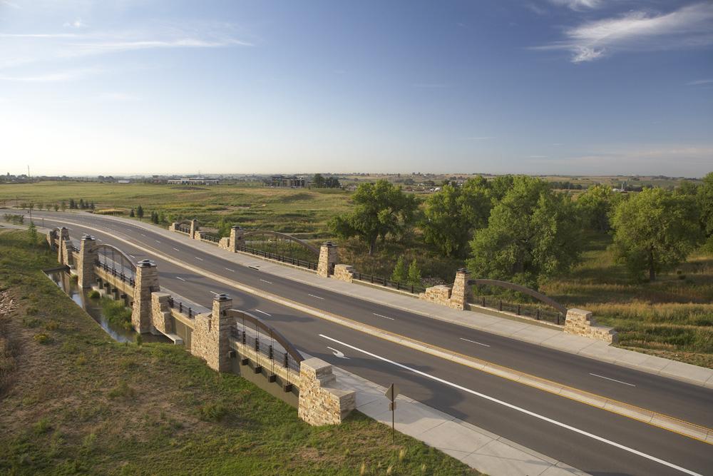
 DISTRICT Map District Description Located within the northern portion of the Centerra, District D, the Northern District, provides an opportunity to")

3 LOCATION MAP AND DISTRICT DESCRIPTION District and Key Map Major Pedestrian System G Crossroads Boulevard Sub-Area Rocky Mountain Avenue Sub-Area Internal Core Sub-Area Motorplex at Centerra F I-25 Corridor Sub-Area (see also special conditions) DISTRICT Map District Description Located within the northern portion of the Centerra, District D, the Northern District, provides an opportunity to establish a dynamic gateway image designed to announce the entrance into the Centerra Planned Community. From the North, this District provides a unique opportunity for a variety of uses primarily oriented towards flex-office, commercial, light industrial, office-showroom, and auto dealership pursuits in a Master-Planned context. Specifically, it is envisioned that In-Line and Large Format Retail uses will dominate Crossroads Boulevard, sprinkled with various Pad building sites catering to the convenience needs of motorists. Flex Office and Research and Development uses, primarily located contiguous to Rocky Mountain Avenue, will create a mid-level technology image designed to promote streetscape continuity by linking District D to the professional office oriented environment of the neighboring Lakefront District. Dominating the interior of District D, Light and High Bay Industrial uses, characterized by flex-office, light manufacturing, and warehouse/distribution functions, will cater to the needs of higher-intensity industrial users, surrounded and buffered by lower-intensity office functions and auto dealerships. Auto Dealerships, primarily located parallel to Interstate 25, will gain ample freeway exposure and visibility, with sales pavilions oriented towards I-25, internalizing major parking fields of inventory and auto repair facilities. D-3


4 DISTRICT IMAGE Guidelines Standards ( S ) District and Characteristics 1.0 SITE PLANNING 1.1 High-visibility uses, such as Large Format Retail and Auto Dealerships, are envisioned to be located adjacent to Interstate 25 for maximum freeway exposure. 1.2 In-Line Retail, Pad sites, and Large Format Retail are envisioned to be oriented towards Crossroads Boulevard, maximizing motorist convenience. 1.3 Flex Office and Research and Development uses are envisioned to be oriented contiguous to Rocky Mountain Avenue, promoting streetscape continuity leading from neighboring District B. 1.4 Light and High Bay Industrial uses are envisioned to be located internal to the site, surrounded by lower-intensity and higher image functions. 1.5 Flex Office and Research and Development buildings frame formal open space to be part of each site. 1.6 Light and High Bay Industrial loading docks located internal to the site, screened from public view. 1.7 Auto Dealership repair facilities located internally, buffered from public view. 1.8 Auto Dealership inventory parking to be located out of view of I Individual site developers shall incorporate Master Developer established context, streetscape, landscape, connectivity, etc. in individual site design Allow vehicular passage between individual parcels. Reciprocal Access Agreements are desired, designed to allow the passage of vehicles and pedestrians between adjacent parcels. D ARCHITECTURE IN-LINE RETAIL: 2.1 Architecture characterized as Contextual Agrarian, utilizing indigenous building materials used in a modern fashion. 2.2 Large anchor tenant complemented by a series of individual commercial storefronts. 2.3 Storefront transparency is prominent, composed of large storefront windows and transoms providing ample daylighting. LARGE FORMAT RETAIL: 2.4 Contextual Agrarian Architectural expression characterized by indigenous building materials used in a modern fashion. 2.5 Large building masses broken into scale-giving elements including entrance pavilions, tower elements, cornice/parapet elements, pitched roof overhangs, and structural bays composed of articulated piers and spandrels. 2.6 Articulated building entrances such as gabled pavilions, are designed to announce entrance into the building. 2.7 Glazed entrance pavilions designed to provide internal daylighting. 2.8 Use of trellis elements and arcades to provide rich layering designed to break-up large expanses of façade area. FLEX OFFICE AND RESEARCH AND DEVELOPMENT: 2.9 Contemporary architecture characterized by durable building materials and modern fenestration, compatible with Contextual Agrarian architecture used elsewhere in the district Standalone architecture often times containing start-up or incubator uses Smaller-scaled structural bays composed of piers, spandrels, and window area oriented towards the public realm. LIGHT AND HIGH BAY INDUSTRIAL: 2.12 Contemporary architectural expressions characterized by durable building materials, compatible with Contextual Agrarian architecture used elsewhere in the district Large building masses divided by structural bays into a series of individual components Easily identifiable building entrances with optimum transparency Dock-high doors screened from public view through effective site planning, and the use of landscaping, berming, and screen walls Durable building materials including concrete, masonry, glass, stucco, and standing seam metal. AUTO DEALERSHIPS: 2.17 Contemporary Contextual architectural expressions characterized by the use of indigenous building materials used in a contemporary fashion, compatible with contextual agrarian architecture used elsewhere in the district Contemporary building massing and roof forms characterized by parapets and vaults. District Characteristics 2.19 A uto showrooms with ample glazed fenestration designed to display vehicles for sale Auto repair bays oriented internally, screened from public view Compose building massing to highlight display parking along I-25 and to screen inventory parking from view from I LANDSCAPE ARCHITECTURE 3.1 Use of landscaping to screen and soften building architecture. 3.2 Large landscape buffer contiguous to Interstate 25 announces entrance into District D. 3.3 Landscape medians and islands break-up large expanses of pavement in parking fields. 4.0 SIGNAGE 4.1 In-Line and Large Format Retail signage promotes a lively shopping environment, characterized by wall and projecting signs that complement the Contextual Agrarian architectural image. 4.2 Flex Office and Research and Development signage characterized by monument and wall signage, reflecting a contemporary architectural image. 4.3 Signature wall signage is possibly used to identify individual Auto Dealerships. 4.3 Monument signage will only be allowed to identify major projects, such as a retail shopping center, business campus, or auto mall.


5 SITE PLANNING - I-25 Corridor Sub-Area Vignettes Conceptual Site Plan Customer Parking Provide customer parking convenient to auto showrooms and primary entrance to buildings. Porte Cocheres Create covered porte cocheres designed to shelter patrons from the elements. Auto Mall Dealership Monument Signage Locate business identification monument signage at designated locations,alongtest Drive,utilizing Motorplex standard prototype. Fig. 3 - Provide Porte Cochere s designed to shelter patrons from the elements. Landscape Islands Use landscape islands to break-up large expanses of pavement. v i Auto Repair Facilities For auto dealerships, locate repair facilities internally, screened from public view. Fig. 4 - Orient auto repair facilities internally,screened from public view, cradling the service bays. Fig. 5 - Create auto inventory parking garages that reflect the architectural style of the auto dealership. Fig.6 - Create landscaped parkstrips, oriented towards the public realm. Notice how the clustered tree pattern allows ample visibility to auto display pads. st T e Employee Parking Locate employee parking internally, behind buildings, screened from public view. 2 5 Inventory Parking Create long term auto dealership parking fields, designed to store auto inventory. Locate auto dealership inventory parking primarily oriented towards Test Drive. Building Perimeter Landscaping Provide building perimeter landscaping designed to soften building elevations. Outdoor Plazas Create outdoor plazas designed to accommodate patrons, employees, and vehicle display. C O R R I D O R Fig. 2 - Orient auto dealership showrooms towards the Test Drive theme street. I N T E R S T A T E Fig. 1 - Create automobile staging areas designed to accommodate test drive vehicles. D r Display Pads For auto dealerships, locate auto display pads at designated corner locations, designed to place vehicles in a visually pleasing setting. e Pedestrian Connectivity Create a strong network of sidewalks and walkways designed to provide opportunities for pedestrians to walk safely and conveniently from one location to another. 2.0 CIRCULATION AND PARKING 2.1 Locate convenience parking contiguous to building frontages designed to accommodate business patrons of Auto Dealership parcels (fig. A). 2.2 Locate service, repair, and maintenance parking internally screened from public view (fig. 4, A). 2.3 Allow vehicular passage between individual parcels. Provide shared access driveway along Test Drive contiguous to side property lines to prevent excessive curb cuts. 2.4 S Use landscape medians and islands to shade and screen employee, service, and customer parked vehicles, while physically breaking-up large expanses of pavement (fig. A). 2.5 Locate auto dealership inventory parking internally, primarily oriented toward Test Drive (fig. A). 2.6 Locate auto dealership display pads only in designated locations oriented toward the public streetscape, for maximum exposure (fig. A). 2.7 S Establish strong pedestrian linkages, via sidewalks and trails, to connect all sites together and to provide convenient and safe passage through parking fields. Sales Showrooms For auto dealerships, orient showrooms towards Test Drive. Building Orientation Orient auto dealership buildings, showrooms, and building mounted signs towardstest Drive,designed to maximize visibility and exposure. Streetscape Landscaping Provide ample landscaped parkstrips planted with low drifts of shrub masses designed to frame views to individual dealerships. The pattern and material palette shall be consistent from site to site. Interstate Oriented Display Pads Orient display pads towards I-25, provide in designated locations, only. Ceremonial Building Entrances Locate auto dealership lobbies towards Test Drive, designed to announce entrance. Shared Entry Align shared entry drives across Test Drive. Fig. A 1.0 BUILDING SITING AND ORIENTATION 1.1 S Orient auto dealership showrooms towards the Test Drive theme road designed to gain maximum visual exposure (fig. 1, 2, A) and accommodate pedestrian movements (fig. 1, 2, A). 1.2 S Orient auto service, repair, and maintenance portions of buildings away from public view (fig. 4, A). 1.3 Site buildings to cradle and frame meaningful formal open space, designed to accommodate auto staging areas outdoor forecourts, plazas, and pedestrian gathering spaces (fig. A). 1.4 S Vehicles may be displayed in designated locations only. Vehicles shall not be displayed in landscape areas, setbacks, or adjacent to curb cuts. 1.5 Create covered porte cocheres designed to shelter patrons from the elements (fig. A). 1.6 Create forecourts designed as auto dealership staging areas (fig. A). 1.7 For specific building setback, please refer to the Millennium General Development Plan. Entrance Forecourts Create forecourts designed to announce entrance into auto dealership showrooms. 4.5 S Screen salvaged or damaged vehicles from public view with a decorative solid masonry wall. 1. Establish a Front Door to Centerra by orienting building and landscaping towards the internal test drive theme road. 2. Create parking field orientations that limit their exposure to the I-25 Corridor. 3.0 SITE ACCESS 3.1 Create double-frontage lots designed to accommodate multiple site access points (fig. A). 3.2 Provide site access points contiguous to Test Drive and loop road (fig. A). 3.3 Align on-site internal streets and drives with neighboring parcel driveways across Test Drive, (fig. A). 3. Use building masses to break-up large expanses of pavement. 4.0 SERVICE AND DELIVERY AREAS 4.1 S Avoid placing service and delivery areas where they are visible from public streets. 4.2 S Locate loading docks, trash enclosures, and service areas internally, screened from views from adjacent roadways by buildings. Do not locate loading docks, trash enclosures, and service facilities in setback areas. 4.3 Create shared service areas. Align service areas with those of adjacent buildings so that service drives may be shared between adjacent uses. 4.4 Locate auto repair facilities internally screened by buildings from the public view (fig. A). 5. Promote a unified site plan and landscape character in the sub-area, with potential variety architectural expansion. 4. Internalize distribution, service, delivery, and auto repair facilities, screened from public view. D-5


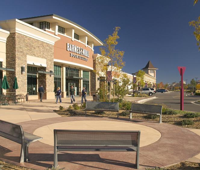
6 SITE PLANNING - Crossroads Boulevard Sub-Area Conceptual Site Plan - In-Line Retail and Pad Buildings Parkstrip Create an ample landscape parkstrip contiguous to Crossroads Boulevard, designed to soften the streetscape and accommodate grade transitions while allowing visibility to retail establishments. Outdoor Patios Create outdoor patios in appropriate exposures, to accommodate patrons of food service establishments. Vignettes Pad Buildings Locate Pad Buildings contiguous to Crossroads Boulevard, designed to optimize retail exposure, while anchoring intersection corners. Landscape Islands Create landscape islands designed to define on-site internal streets while punctuating the ends of parking bays. Site Access Provide site access from minor roadways, such as Byrd Drive. Reciprocal Access Provide Reciprocal Access designed to allow unencumbered egress between adjacent parcels. Outdoor Storage Create outdoor storage yards, screened from public view by solid masonry screen walls, that reflect the architectural style of the retail center. Loading Docks Locate loading docks towards the rear of the site, screened from public view, through the use of decorative walls. Fig. A Convenience Parking Provide convenience parking adjacent to pad buildings, providing easy access. Landscape Medians Create landscape medians designed to break-up large expanses of pavement, and to accommodate pedestrian connectivity. Pedestrian Promenade Create a pedestrian promenade designed to link individual retail storefronts while accommodating pedestrian gatherings. Pedestrian Connectivity Create a strong network of sidewalks and walkways designed to provide opportunities for pedestrians to walk safely and conveniently from one location to another. Storefronts Orient storefronts towards the streetscape and pedestrian promenade, designed to optimize visibility and exposure. Building Perimeter Landscaping Provide building perimeter landscaping designed to soften building elevations and shade pedestrians. Site Perimeter Landscaping Provide perimeter landscaping, creating a soft green transition between parcels. Fig. 1 - Use buildings to frame and enclose meaningful, formal open space. Notice how these In-Line Retail buildings create a pedestrian forecourt. Fig. 4 - Create outdoor patios associated with pad buildings designed to accommodate opportunities for pedestrian gatherings and outdoor dining. Fig. 2 - Orient pad buildings towards the public streetscape to optimize exposure. Locate pad buildings at corners, designed as gatepost entrance features. Fig. 5 - Orient In-Line Retail buildings towards the pedestrian promenade, creating window shopping opportunities. Fig. 3 - Orient In-Line Retail storefronts towards entrance forecourts, cradling outdoor pedestrian plazas and promenades. Fig. 6 - Orient perimeter landscaping adjacent to buildings. Notice how the dense evergreen border softens In-Line Retail architecture D-6 Site satellite pad buildings at street frontages and higher intensity corner locations. Locate buildings to create and frame meaningful open space. Site satellite pad buildings and Large Format retail structures to break-up large expanses of pavement. Establish clear circulation between and amongst all sites and uses. Design ample drive-thru facilities that contain stacked vehicles while sensitively accommodating pedestrian movements. Sensitively site service, delivery, and outdoor equipment storage facilities to minimize their visual impact. 1.0 BUILDING SITING AND ORIENTATION 1.1 Locate architecturally significant satellite pad site buildings at street intersections designed to anchor the corner. (fig. A, B) 1.2 Locate In-Line Retail storefronts to create and frame pedestrian promenades creating meaningful formal open space (fig. 1, 5, 7, A, B). 1.3 Orient freestanding satellite pad building storefronts towards the street or formal open space areas such as patios (fig. 1, 4, A, B). 1.4 Avoid locating parking lots between the street and satellite Pad Buildings. 1.5 Separate Pad sites from large parking fields with drive aisles and landscape medians designed to define pad site parking areas (fig. A, B). 1.6 Orient building entries so they are easily identifiable from parking lots (fig. 7). 1.7 Locate satellite and Large Format Retail buildings to create dispersed parking fields (fig. A, B). 1.8 Orient Large Format building entrances towards pedestrian promenades and entrance forecourts (fig. 7, A, B). 1.9 Orient building masses to frame and enclose pedestrian forecourts (fig. 1) Orient pedestrian colonnades contiguous to building frontages, creating a shaded and sheltered pedestrian promenade (fig. 10) Locate articulated Large Format entrances along pedestrian promenades designed to highlight entrance into Large Format structures (fig. 7) Create pedestrian forecourts at Large Format building entrances designed to accommodate pedestrian gatherings and cart storage (fig. 7, 8). 2.0 FORMAL OPEN SPACE 2.1 Orchestrate the placement of In-Line Retail buildings to frame and enclose meaningful formal open space areas creating pedestrian friendly promenades, forecourts, courtyards, and plazas (fig. 1, 3, 5, 7, 8, 9, A, B). 2.2 Avoid random accumulations of buildings characterized by leftover, awkward, and unusable open space areas. 2.3 Orient formal open spaces to views of site amenities and activities such as architectural landmarks, fountains, and landscape features (fig. A). 2.4 Link formal open space areas, such as forecourts, plazas and courtyards, to pedestrian promenades (fig. 1, 3, 4, 7, 9, A). 2.5 Create outdoor patios associated with pad site fast food establishments, designed to accommodate pedestrian gatherings and al-fresco dining (fig. A, B,). 3.0 SITE ACCESS 3.1 Coordinate entry points into individual parcels with the Master Plan to confine or limit vehicular and pedestrian conflicts (fig. A, B). 3.2 Use mid-block street intersections along minor roadways such as Byrd Drive, to provide access into the site (fig. A, B). 3.3 Share entrance driveways with neighboring parcels. Reciprocal Access Agreements are desired, designed to allow the passage of vehicles between adjacent parcels (fig. A). 3.4 Design entrance points to align with on-site focal points such as building entrances, landmark towers and formal open space features. 3.5 S Maintain a minimum separation of 200 feet between public street center lines or otherwise required from the City of Loveland (fig. A, B). 3.6 S Do not locate entrance driveways near roadway intersections. Entrance driveways should be located a minimum 200 feet from the center line of roadway intersections or otherwise required from the City of Loveland (fig. A, B). 4.0 CIRCULATION 4.1 Do not wall-off commercial sites from surrounding office and light industrial land uses. 4.2 Provide pedestrian and vehicular connectivity between the In-Line Retail site and adjacent office and light industrial land uses (fig. A, B). 4.3 Use on-site internal streets as direct extensions of adjacent public streets, providing convenient and direct vehicular and pedestrian access to the site (fig. A, B). 4.4 Maintain a similar parking aisle direction between adjacent parking lots (fig. A, B). 4.5 Provide strong pedestrian connections between various uses within the Crossroads Boulevard Sub-Area (fig. A, B). 4.6 S Establish strong pedestrian linkages via sidewalks and trails to connect all uses together, promoting convenient and safe passage through parking fields. 5.0 DRIVE-THRU S 5.1 S Design satellite pad site drive-thru lanes to provide sufficient vehicle stacking behind the menu board to accommodate a minimum of six cars.


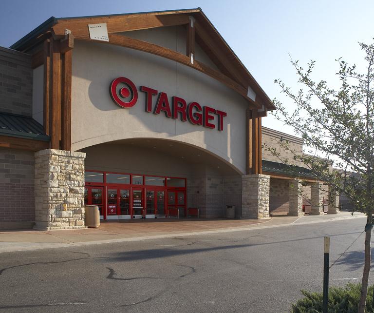
7 Vignettes SITE PLANNING - Crossroads Boulevard Sub-Area Conceptual Site Plan - Large Format Retail and Pad Buildings Fig. 7 - Orient Large Format entrances towards the public realm. Notice how the trellis element enhances the pedestrian promenade. Fig. 8 - Use building masses to frame and enclose pedestrian forecourts and plazas. Notice how the buildings frame and enclose the outdoor patio. Fig. 9 - Create promenades designed to accommodate pedestrians. Notice how the ample promenade with associated landscaping creates a continuous pedestrian landing. Parkstrip Create an ample landscape parkstrip contiguous to Crossroads Boulevard, designed to soften the streetscape and accommodate grade transition, while allowing visibility to retail establishments. Outdoor Patios Create outdoor patios in appropriate exposures to accommodate patrons of food service establishments. Architecturally Significant Buildings Locate Pad Buildings contiguous to Crossroads Boulevard, designed to anchor intersection corners announcing entrance into the Large Format Retail Center. Convenience Parking Provide convenience parking adjacent to pad buildings, providing easy access. Landscape Medians Create landscape medians designed to break-up large expanses of pavement, and to accommodate pedestrian connectivity. Pedestrian Connectivity Create a strong network of sidewalks and walkways designed to provide opportunities for pedestrians to walk safely and conveniently from one location to another. Pedestrian Promenade Create a promenade as a pedestrian gathering space, designed to accommodate the loading and unloading of passengers and merchandise. Building Perimeter Landscaping Provide building perimeter landscaping designed to soften building elevations. Articulated Entrances Create articulated building entrances designed to announce entrance into Large Format architecture, while increasing façade variety and visual interest. Outdoor Storage Create outdoor storage yards, screened from public view by screen walls, that reflect the architectural style of the retail center. Pedestrian Forecourts Use building masses to frame and enclose pedestrian forecourts. Fig Orient pedestrian colonnades contiguous to building frontages, contained within the pedestrian promenade, designed to shade and shelter pedestrians. Fig Orient loading docks towards the side or rear of Large Format buildings, screened from public view. Fig Create building perimeter landscape buffers designed to soften Large Format architecture. Loading Docks Locate loading docks towards the rear of the site, screened from public view. Fig. B Landscape Buffer Create a substantial landscape buffer contiguous to Interstate 25, designed to soften Large Format architecture while maintaining building identity. 5.2 Discourage pedestrian walkways that intersect with pad site drive-thru lanes. 5.3 Separate drive-thru lanes from site access points. 5.4 S Provide ample drive-thru aisle width based upon the following standards: Drive-thru Aisle Width: - Curved Sections: 12 feet - Straight Sections: 11 feet 5.5 S Sensitively locate drive-thru circulation aisles. Drive-thru aisles shall be located a minimum of 20 feet from the public right-of-way. 6.0 PARKING FIELDS 6.1 Segment large parking lots into smaller courts enclosed and framed by tree rows designed to minimize the perceived scale of the total parking area (fig. A, B). 6.2 Align parking medians perpendicular to building entries. This alignment minimizes obstacles to pedestrians and encourages walking to remote parking lots (fig. A, B). 6.3 Use curbed landscape medians to shade and screen parked vehicles, while physically breaking-up large expanses of pavement (fig. A, B). 6.4 Provide landscaped islands designed to terminate the ends of parking aisles (fig. A, B). 6.5 Border parking areas with concrete curbs and gutters. Avoid ribbon gutters that drain down the center of drive aisles. 6.6 Discourage high-speed driving. Use bulb-outs, round-abouts, and textured pavement treatments to slow vehicles. 6.7 Provide separate convenience parking fields for satellite pad sites, buffered from long term parking areas (fig. A, B). 7.0 SERVICE, DELIVERY, AND OUTDOOR STORAGE AREAS 7.1 Avoid placing service and outdoor storage areas where they are visible from adjacent buildings. 7.2 Locate loading docks, trash enclosures, service facilities, and outdoor storage areas outof-view from adjacent roadways, pedestrian walkways, and formal open space amenities (fig. 11, A, B). 7.3 S Do not locate loading docks, trash enclosures, service facilities, and outdoor storage areas in setback areas. 7.4 Provide separate parking areas for delivery trucks and service vehicles located away from parking lots and pedestrian promenades (fig. 11). 7.5 Create shared service areas. Align service areas with those of adjacent buildings so that service drives may be shared between parcels. 7.6 S Locate loading docks, trash enclosures, service facilities, and outdoor storage areas a minimum of 20 feet from any public street ROW, screened from public view (fig. 11, A, B). 7.7 S Screen pad site service facilities and trash enclosures from public view with solid masonry decorative walls, reflective of the architectural style of the pad building. D-7


8 SITE PLANNING - Rocky Mountain Avenue Sub-Area Vignettes Conceptual Site Plan - Flex Office and Research and Development Building Articulation Articulate building masses designed to distinguish and define plazas and entrance forecourts. Plazas Use buildings to frame and enclose meaningful formal open space. Reciprocal Access Provide reciprocal access between individual adjacent parcels. Landscape Islands Create landscape islands designed to soften large expanses of pavement. Shared Parcel Access Locate parcel access points on property lines to create shared entrance driveways. Site Access Locate parcel access points away from major intersections. Employee/Service Parking Locate employee parking internal to the site, designed to accommodate employees and services. Convenience Parking Locate convenience parking adjacent to the streetscape, designed to accommodate patrons. Pedestrian Connectivity Create a strong network of sidewalks and walkways designed to provide opportunities for pedestrians to walk safely and conveniently from one location to another. Entrance Forecourts Provide entrance forecourts designed to accommodate pedestrian gatherings. Flex Office Regional Detention Create aesthetically pleasing detention ponds designed to capture and contain surface run-off. Research and Development Fig. 3 - Create usable formal open space. Notice how the building mass defines and encloses the pedestrian forecourt. Fig. 4 - Create ample parkstrips to buffer parking fields. Use earth berms, hedges, and street trees to create a soft streetscape, designed to screen buildings and parking fields. Fig. 5 - Screen loading docks from public view, buffering the service and delivery area. Fig. 6 - Provide building perimeter landscaping to soften façades. Notice how the hedges, shrubs, and perimeter trees provide a rich landscape layer, buffering the building from the parking field. Loading Docks Locate loading docks internal to the site, screened from public view by landscaping, building masses, and screen walls. Site Perimeter Landscaping Provide ample landscaping contiguous to parcel property lines designed to harmonize with adjacent lots. Fig. A Landscape Medians Create landscape medians to break-up large parking fields. 1. Create building orientations that enhance and frame the streetscape contiguous to Rocky Mountain Avenue and Internal streets. 2. Use building masses to break-up large expanses of pavement. 3. Locate buildings to frame and enclose meaningful formal open space. 4. Create individual internalized parking courts designed to enclose and screen parking. 5. Internalize distribution, service, and delivery facilities screened from public view. 1.0 BUILDING SITING AND ORIENTATION 1.1 Orient office bays related to Research & Development buildings towards the public streetscape, contiguous to Rocky Mountain Avenue (fig. 3, A). 1.2 Orient technology portions of Research & Development buildings towards rear distribution facilities (fig. A). 1.3 Site buildings to cradle and frame meaningful formal open space, designed to accommodate outdoor forecourts, plazas, and pedestrian gathering spaces (fig. 1, 2, 3, A). 1.4 Site front building facades contiguous to perimeter pedestrian promenades designed to accommodate pedestrian movements (fig. 3, 6, A). 1.5 Orient distribution, service, and delivery facilities towards the rear of Research and Development sites, screened from public view (fig. 5, A). 1.6 Orient Flex Office ceremonial entrances towards the public realm, designed to accommodate patrons (fig. 3, A). 1.7 Orient Flex Office functional entries towards internal parking areas, designed to accommodate employees (fig. A). 1.8 Avoid locating long-term parking between the roadway and building (fig. A). 2.0 VEHICULAR CIRCULATION AND PARKING 2.1 Locate convenience parking contiguous to Rocky Mountain Avenue designed to accommodate business patrons of both Flex Office and Research and Development parcels (fig. A). 2.2 Locate employee, distribution, service, and delivery parking internally within Flex Office D-8 Fig. 2 - Create defined open space areas designed to accommodate pedestrian amenities. Notice how the buildings and associated colonnade enclose the outdoor lunchroom. Pedestrian Forecourts Create forecourts designed to accommodate pedestrian gatherings while announcing entrance into the building. Building Perimeter Landscaping Provide building perimeter landscaping designed to soften architecture. Use trellis elements or colonnades to provide rich layers designed to visually break-up continuous building masses. Parkstrip Provide ample landscaping contiguous to Rocky Mountain Avenue, designed to screen convenience parking fields. Fig. 1 - Use buildings to frame and enclose meaningful open space, cradling and defining formal plazas and greens. parcels, screened from public view (fig. A). 2.3 Allow vehicular passage between individual parcels. Reciprocal Access Agreements shall be required, designed to allow the passage of vehicles and pedestrians between adjacent parcels. 2.4 Use landscape medians and islands to shade and screen parked vehicles, while physically breaking-up large expanses of pavement (fig. A). 3.0 SITE ACCESS 3.1 Limit the number of entry access points along Rocky Mountain Avenue designed to confine or limit vehicular and pedestrian conflicts while facilitating traffic flow (fig. A). 3.2 Align on-site internal streets with neighboring parcel driveways across from each other (fig. A). 3.3 Create shared parcel access points designed to accommodate joint use driveways (fig. A). 4.0 SERVICE AND DELIVERY AREAS 4.1 Avoid placing service and delivery areas where they are visible from public streets. 4.2 Locate loading docks, trash enclosures, and service areas out-of-view from adjacent public roadways, pedestrian walkways, and formal open space amenities (fig. 5). 4.3 Locate loading docks, trash enclosures, and service areas internally, screened from adjacent roadways by buildings (fig. 5). 4.4 S Do not locate loading docks, trash enclosures, and service facilities in setback areas. 4.5 Create shared service areas. Align service areas with those of adjacent buildings so that service drives may be shared between adjacent Flex Office uses.


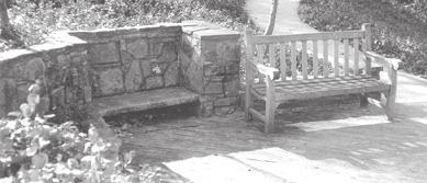
9 Vignettes SITE PLANNING - Internal Core Sub-Area Conceptual Site Plan - Light and High Bay Industrial Parkstrip Provide ample parkstrip landscaping designed to screen and soften parking fields. Parcel Access Locate parcel access points away from major intersections, in compliance with City of Loveland requirements. Building Entries Articulate building masses designed to accentuate building entries. Regional Detention Provide detention basins to capture surface run-off, and to serve as a neighborhood park space. Light Industrial Fig. 7 - Orient building entries towards the streetscape. Notice how the entrance pavilion functions as an identifiable icon, visible from the public realm of the streetscape. Fig. 8 - Create and define pedestrian gathering areas. Notice how the building frames the outdoor seating area. Fig. 9 - Orient distinct building entrances towards the public realm. Notice how the articulated and easily-identifiable building recess announces entrance. Building Articulation Articulate building masses to distinguish individual Light Industrial spaces. High Bay Industrial Pedestrian Connectivity Create a strong network of sidewalks and walkways designed to provide opportunities for pedestrians to walk safely and conveniently from one location to another. Building Perimeter Landscaping Provide landscaping adjacent to High Bay Industrial buildings, designed to screen and soften building architecture. Service Areas Create shared service and distribution areas. Align service and distribution areas with those located on adjacent parcels within the sub-area, so that tractortrailer staging areas may be shared. Dock-High Doors Locate dock-high doors internal to the site, screened from public view through the use of buildings, landscaping, and screen walls. Landscape Islands Provide landscape islands designed to break-up large expanses of pavement. Fig Use dense parkstrip landscaping to buffer large industrial buildings. Notice how the street tree clusters and ample earth berm screens the building from public view. Fig Screen service areas. Notice how the screen wall, coupled with landscaping, buffers the loading dock. 1.0 BUILDING SITING AND ORIENTATION 1.1 Locate office portions of Light Industrial and High Bay Industrial buildings contiguous to roadways, designed to frame the streetscape (fig. 7, 9). 1.2 Locate Light and High Bay Industrial buildings to accommodate convenient on-site parking adjacent to buildings (fig. B). 1.3 Locate Light Industrial buildings to accommodate both street-oriented patron parking and rear-oriented employee parking (fig. B). 1.4 Locate High Bay Industrial buildings towards the roadway designed to screen rearoriented warehouse and distribution facilities (fig. B). 1.5 Take advantage of mutual benefits such as shared driveways, and service aisles (fig. B). 1.6 Locate building entries so they are easily identifiable from site access points (fig. 7, 9). 1.7 Articulate buildings to accommodate ceremonial building entries (fig. 7, 9). 2.0 ACCESS AND DRIVEWAYS 2.1 Limit parcel access points along arterial roadways to enhance traffic flow and minimize the disruption of landscaping and medians (fig. B). 2.2 Align secondary internal street driveway access points with access to properties across the street, whenever possible (fig. B). 3.0 DISTRIBUTION, SERVICE, DELIVERY, AND STORAGE AREAS 3.1 Avoid placing distribution, service, delivery, and storage areas where they are visible from public streets (fig. B). Fig Create pedestrian promenades designed to link individual businesses. Tractor-Trailer Staging Area Orient big-rig distribution areas internally, buffered from public view by buildings, landscaping, and screen walls. 3.2 Restrict the location of distribution, service, delivery, and storage facilities to defined areas to the rear or side of buildings (fig. B). 3.3 S Locate accessory structures behind buildings. Accessory buildings shall not be placed between the roadway and front building elevations. 3.4 Locate distribution, service, delivery, and storage areas out-of-view from adjacent roadways, entry drives, internal streets, pedestrian walkways, and formal open space (fig. 11, B). 3.5 Provide separate parking areas for big-rig distribution vehicles, delivery trucks, and service vehicles located away from street-oriented employee parking lots and pedestrian walkways (fig. 11). 3.6 Create shared service areas. Align service areas with those on adjacent parcels so that service drives may be shared (fig. B). 3.7 S Do not locate service, delivery, and storage areas in setback areas Use building placements and decorative architectural screen walls, coupled with landscaping, to screen distribution, service, delivery, and storage areas from public view (fig. 11). 3.9 S Service, delivery, and storage areas shall be constructed and maintained according to the following requirements: - No materials, supplies, or equipment, including trucks or other motor vehicles, shall be stored on-site, except inside a closed building or behind decorative screen walls to prevent visibility from neighborhood parcels and roadways. - Distribution, service, delivery, and storage areas (including dock-high doors) shall be screened (fig. 11). - Screen walls shall harmonize with the architectural style of the adjacent building, constructed of similar complimentary materials and finishes (fig. 11). 4.0 COMMUNICATION DEVICES 4.1 Locate transmission and receiving telecommunication equipment (i.e., satellite dishes) at ground level, behind Light and High Bay Industrial structures, screened from public view. Fig. B Customer and Employee Parking Locate customer and employee parking contiguous to the streetscape. Provide office portions of buildings along the perimeter of District D, while concentrating light industrial and warehouse and distribution uses internally. Provide patron parking contiguous to roadways while concentrating distribution facilities towards the rear of the parcel, behind buildings. Provide buildings and screen walls to buffer distribution, service, and delivery areas. Locate distribution, service, delivery, and storage facilities internally or towards the rear of sites, screened from public view. D-9


10 ARCHITECTURE - Auto Dealerships Clerestory Windows Clerestory windows provide ample daylighting. Fenestration Clerestory windows divided by mullions into individual window panes. Prototypical Elevation Architectural Image Traditional standing seam metal roof and ashler-laid stone base, used in a contemporary fashion, promotes a contemporary contextual architectural image. Building Mass Large rectilinear building mass punctuated with smaller subordinate volumes creates streetscape variety and visual interest. Cornice Element Distinctive cornice element terminates the top of flat roof sections. Vignettes Roof Material Vault capped with a standing seam metal roof adds roofscape texture. Corner Towers Vaulted projecting tower elements anchor building corners. Roof Overhang Substantial projecting roof eave terminates the top of the vault, creating rich shadow lines. Roof Form Vaulted roof forms coupled with flat roof segments create roofscape variety and visual interest. Mechanical Equipment Mechanical equipment contained within the roof vault, is screened from public view. Fig. 1 - Create distinctive showroom pavilions. Notice how the entrance pavilion punctuates the roofscape, creating a monumental entrance. Fig. 2 - Use roof forms consistently. Notice how the vaulted roof forms are repeated, creating roofscape continuity and visual interest. Fig. 3 - Use traditional building materials in a contemporary fashion. Notice the use of natural stone and standing seam metal that projects a contemporary contextual image. Building Base Stone masonry base anchors the building to the ground plane, creating a pedestal for the building to rest upon. Building Materials Sturdy ashler-laid stone base provides a sturdy foundation, supporting the stucco clad façade above. Showroom Pavilion Showroom pavilion oriented towards the streetscape announces entrance into the building, while displaying merchandise. Parkstrip Parkstrip planted with clusters of deciduous and evergreen street trees, allows the display of auto merchandise D-10 Structural Bays Structural bay composed of stone masonry piers and spandrel express the underlying structure of the building. Create auto dealerships that reflect a Contemporary Contextual architectural image. Create auto dealerships that promote streetscape diversity through the use of articulated building masses. Design auto dealerships to avoid long expanses of blank walls and windowless elevations. Auto dealerships shall use building elements such as structural bays, projections, and plane breaks that help segment the building mass into smaller scale-giving components. Orchestrate the placement of windows on sales showrooms to create proportionate and balanced window compositions. Use building materials with strong textures and rich colors, such as stone, that create visual depth and detail. Recessed Entry Showroom entrance is recessed, sheltering patrons from the elements, while adding visual interest to the façade. Staging Area Forecourt provides a platform for pedestrian gatherings and test drives. 1.0 BUILDING MASSING 1.1 Design auto dealership buildings as a collection of volumes that start low at the edges and mass toward the center (fig. A). 1.2 Segment large-scale auto dealerships into a series of individual volumes (fig. 2, A). 1.3 Create discernible auto sales showrooms. Use building projections to create identifiable auto showroom areas (fig. 1, A). 1.5 Use smaller single-story, human-scaled, building volumes as transitional elements to larger building masses, such as entrance pavilions (fig. 1). 1.6 S Parking structures shall be architecturally integrated into the main building. 1.7 S Conceal the view of cars in parking structures through solid screen walls integrated into the building architecture. 2.0 ROOF FORM 2.1 Create roof forms that reflect a Contemporary Contextual architectural image. Use pitched roof forms, vaults, or large flat roof overhangs to shed winter snow, provide summer shade, and shelter pedestrians from the elements (fig. 1, 2, 3,). 2.2 Use a consistent roof form to create building continuity. Satellite auto repair buildings should use the same roof form and materials as used on the primary showroom building (fig. 1, 2, A). 2.3 S Conceal rooftop mechanical equipment. All rooftop mechanical equipment shall be contained within the roof structure, completely screened within a penthouse, or screened by a roof parapet that harmonizes with the architectural style of the building (fig. A). Fig. A Signage Sign band functions to identify the dealership. Fig. 4 - Create auto showrooms that project a contemporary contextual image. Notice how the shed roof form and clerestory windows reflect the agrarian image. 3.0 FAÇADE ARTICULATION 3.1 Reflect the quality and integrity of the underlying structure of the building in a clear and consistent manner through the use of structural bays (fig. 1). 3.2 Use structural bays composed of pier and spandrels designed to segment facades into a series of individual façade components (fig. 1, A). 3.3 Soften building facades through the use of building projections and recesses (fig. 1, A). 3.4 S Create transparent auto dealership showrooms. Use storefront windows and fenestration to display automobiles, oriented towards the public view (fig. 1, A). 3.5 Use projecting colonnades or trellis elements to soften auto dealership building facades. 3.6 S Avoid flush building surfaces. Continuous all glass curtain walls shall not be permitted. 3.7 S Four-sided architecture shall be required. All building elevations shall be of equal finish and quality. 4.0 BUILDING MATERIALS 4.1 Use heavy, visually solid foundation materials that transition upwards to lighter wall cladding and roof materials (fig. A). 4.2 Use material texture, color, control joints, and patterns of materials to add visual interest to building surfaces (fig. A). 4.3 Avoid highly reflective surfaces that generate glare such as mirrored and reflective glass. 4.4 Avoid large, featureless building surfaces. Large all glass curtain walls are typically unacceptable Fig. 5 - Use building form to create automobile staging areas. Notice how the covered porte-cochere provides a platform for passenger loading and unloading. Fig. 6 - Use auto dealership building masses to distinguish parking and display areas. Notice how the auto display area is oriented towards the street. unless used in combination with building structural bays that can provide a sense of scale and rhythm. S The following building materials shall be permitted: All material transitions shall occur at inside corners. Building Base and Façades: - Concrete, poured-in-place or pre-cast (sandblasted or textured) - Concrete, with colored aggregate - Masonry, Brick (i.e., Face Brick, FBX) - Masonry, Split face concrete block - Masonry, Stone Veneer (i.e., Brownstone, Sandstone, Slate) - Masonry, Stone (i.e., Ashler-laid, Broken Rangework) - Metal (such as I-beams, Corten steel, corrugated metal and composite metal panel s e.g., stainless steel, copper, titanium, zinc ), subject to DRC review and approval - Stucco (Upper Stories only) Windows: - Glass, Transparent - Glass, Lightly tinted (Allowing 80 percent light transmission, minimum) Roofs: - Metal, Standing Seam - Metal, Corten Steel - Flat Tile, (Modern Slate) - Rolled metal or rubber membrane roofing (flat roof sections, only. Screened by a parapet wall and associated cornice)


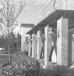
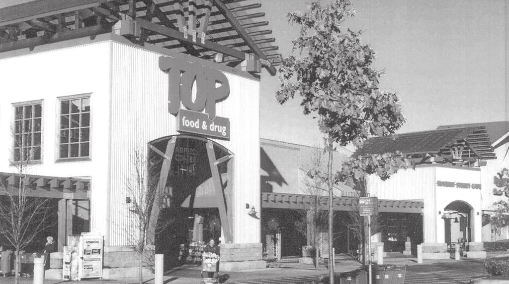
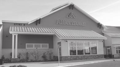
11 Vignettes Prototypical Elevation ARCHITECTURE - Large Format Retail Roof Form Multiple gable roof forms create roofscape variety and visual interest. Building Massing Agrarian-oriented building mass reminiscent of rural barn structures. Notice how the building starts low at the edges, and masses towards the center. Roof Monitor Roof monitor punctuates the roofscape, enhancing visual interest while concealing mechanical equipment. Roof Planes Multiple roof planes create roofscape variety and visual interest. Fig. 7 - Use a variety of building volumes to increase Large Format visual interest. Notice how the smaller, single-story shed roof building mass functions as a stair step to larger building volumes. Fig. 8 - Use trellis elements to soften Large Format architecture. Notice how the substantial stone pier and dimensional timber trellis structure add façade variety and visual interest. Notice also that cart storage is shaded. Fig. 9 - Terminate the top of Large Format buildings with a roof cap, providing a building terminus while creating rich shadow lines. Notice how the various gable roof forms create roofscape variety and visual interest. Roof Fascia Substantial roof fascia composed of an ample eave overhang creates visual stability. Signage Individual cut internally illuminated plastic letters identify the business. Transom Decorative transom adds ornamentation to the entrance pavilion. Cornice/Parapet Wall Cornice terminates the top of the building. Parapet screens rooftop mechanical equipment from public view. Building Volumes Multiple building volumes of various height add visual interest. Single-story volumes function as transitional elements to larger building masses. Corner Towers Tower elements punctuate building corners, providing accent and visual interest. Building Materials Rustic Building materials including corrugated metal, split face concrete masonry, and standing seam metal, project a rugged agrarian image. Fig Use awnings to add variety and visual interest to Large Format façades. Notice also the pitched roof form that reduces the building mass, creating a human-scaled façade. Fig Use building materials to add texture and visual interest. Notice how the stone base anchors the Large Format building to the ground plane, with lighter board and batten walls occurring above. 1.0 BUILDING MASSING 1.1 Use additive elements such as entrance pavilions to break-up Large Format architecture. (fig 12, B). 1.2 Use varied building elements such as towers to accentuate building corners (fig B). 1.3 Use covered arcades and trellis elements as single-story transitional elements to largerscaled building masses (fig 8, B). 2.0 ROOF FORM 2.1 Crown Large Format buildings with a discernible roof cap (fig 7, 8, B). 2.2 Terminate the top of Large Format flat roofs with a substantial roof parapet/cornice element (fig 10, B). 2.3 S Conceal rooftop mechanical equipment. All rooftop mechanical equipment shall be completely screened within a penthouse or hidden behind a roof parapet (fig B). 3.0 FAÇADE ARTICULATION AND TRANSPARENCY 3.1 S Articulate Large Format façades. No façade shall exceed 50 linear feet without a façade articulation. Façade articulation techniques include the following: - Structural piers (fig 9, 10) -Punctuated building corners with material changes (fig 7) - Projecting trellis elements or colonnades (fig 8, 11, B) - Raised planters with landscaping - Faux window openings and awnings Fig Provide functional roof dormers designed to add variety and visual interest to Large Format roofscapes. Notice also the ample façade transparency created by the storefront windows. Arcade Pedestrian arcade shelters patrons from the elements. - Storefront windows - Wall plane projections or recesses (fig 7, B) - Colonnades and trellis elements (fig 8, B) 3.2 Design Large Format façades based upon the following guidelines: Minimum Percentage of Storefront Façade Window Area: 25 Percent Minimum Percentage of Front and Side Façades that face a street or public way that contain an Arcade, Trellis Element, or Colonnade: 50 Percent 4.0 ACCESSORY STRUCTURES 4.1 Design Large Format accessory structures to reflect the architectural style of the shopping center. 4.2 Design service stations and canopies with substantial piers designed to reflect the architectural style of the primary Large Format building. 5.0 BUILDING MATERIALS 5.1 S The following building materials shall be permitted: All material transitions shall occur at inside corners. Building Base: - Masonry, Brick (i.e., Face Brick, FBX) - Masonry, Stone (i.e., Ashler-laid) - Masonry, Stone Veneer (i.e., Brownstone, Sandstone, Slate) - Siding, Metal Pedestrian Promenade Promenade provides ample outdoor gathering space for pedestrians, linking individual In-Line Retail storefronts. Upper Façade: - Masonry, Brick (i.e., Face Brick, FBX) - Masonry, Stone (i.e., Ashler-laid) - Masonry, Stone Veneer (i.e., Brownstone, Sandstone, Slate) - Metal, Corrugated - Metal, Corten - Metal (structural metal such as I-beam spandrels subject to DRC approval) - Siding, Metal - Siding, Clapboards (cementitious) - Stucco or EIPS, Smooth Windows: - Glass, Lightly tinted (Allowing 80 percent light transmission) - Glass, Transparent Roofs: - Tile, Flat (modern slate) - Metal, Corten Steel (pitched roof sections, only) - Metal, Standing Seam (pitched roof sections, only) - Rolled metal or rubber membrane roofing (flat roof sections, only). Screened by a parapet wall and associated cornice Wood: - Wood (Wood may be used as a minor architectural element such as posts, beams, corbels, and brackets) Fig. B Ornamental Lighting Gooseneck lamps complement the architectural style of the building. Building Transparency Storefront windows allow indoor visibility and daylighting. 1. Reduce the apparent mass and bulk of Large Format retail buildings. 2. Terminate the top of Large Format architecture with a distinguishable roof cap. 3. Articulate Large Format building elevations to increase façade variety and visual interest. 4. Provide big box transparency Shelter patrons from the elements at Large Format entrances. Create Large Format buildings and accessory structures that reflect the architectural style of the entire shopping center. D-11


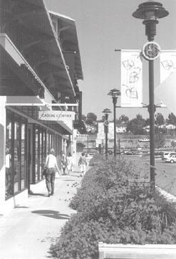
12 ARCHITECTURE - In-Line Retail Prototypical Elevation Vignettes Cornice Element Subtle cornice element terminates the top of the building. Building Materials Building materials composed of clapboard and shingles, projects a rugged and rustic image. Roof Forms Varying pitched and flat roof forms create roofscape visual interest, while terminating the top of the building. Tower Element Tower structure punctuates the roofscape, creating an orientation icon and landmark. Forced perspective makes the tower element appear taller. Colonnade Colonnade composed of piers and trellis structures function as a stair step to larger building masses. Structural Bay Structural bay composed of piers and spandrels frames the storefront window. Building Massing A variety of building volumes create visual interest. Fig. 1 - Punctuate building corners with tower elements. Notice how the tower element extends above the flat roof plane, accentuating the corner building mass. Fig. 2 - Soften building façades with trellis elements. Notice how the trellis, characterized by masonry piers and dimensional timber lattice, creates a shady and sheltered pedestrian promenade. Fig. 3 - Terminate In-Line Retail storefronts with a distinguishable roof cap. Notice how the pitched roof eave overhang signals an end to the façade. Structural Piers Substantial battered stone veneer piers, with distinctive bases, shafts, and capitals, support the dimensional timber trellis structure. Signage Wall signage, composed of internally lighted individual channel letters, coordinate the proportions of the wall signage to be in scale with the wall/facade. Plant Containers Plant containers add decoration to the pedestrian promenade while softening building architecture D-12 Fig. A Create consistent building masses and roof forms that reflect the architectural style of the entire commercial center. Increase building mass at areas of higher intensity and pedestrian concentration Design human-scaled building masses. Incorporate architectural features that create visual interest at the pedestrian scale. Articulate facades to reduce the massive scale and impersonal appearance of large commercial buildings. Use building materials that are human-scaled. Perceiving the scale of a building is important to a pedestrian s ability to relate to it comfortably. Storefront Transparency Ample storefront window provides interior daylighting. Horizontal storefront opening is divided by mullions into three verticallyoriented windows. Pedestrian Promenade Ample pedestrian promenade provides opportunities for gatherings, while accommodating pedestrian movements. 1.0 BUILDING MASSING 1.1 Locate higher-intensity gatepost satellite building masses at corners designed to announce the commercial center (fig. 12). 1.2 Locate higher-intensity building masses towards the center of the building complex. Transition buildings height outward and down to adjacent developments (fig. 4, A, B). 1.3 Punctuate large building masses with towers designed as landmark icons (fig. 1, A). 1.4 Segment buildings with a distinguishable base, middle, and cap (fig. A, B). 1.5 Reduce building mass. Use the following techniques to diminish the size and scale of large commercial buildings: - Variation of roof form and height (fig. 4, 8, 10, A, B). - Variation of building color and texture (fig. 1, A). - Expression of building storefront structural bays characterized by columns/piers and spandrels (fig. 11). - Use of secondary roof forms such as monitors and dormers to add variety and visual interest (fig. 3, 7, 8). - Use of subordinate building masses such as tower elements that add variety and visual interest (fig. 1, A). - Use of arcades, colonnades, and trellis elements that soften building architecture (fig. 1, A, B). Convenience Parking Head-in parking located adjacent to building entrances provides patrons with ample short-term convenience parking. Fig. 4 - Use building materials that reflect an agrarian image. Notice the use of corrugated metal siding which projects a rugged, rustic image. 2.0 ROOF FORM PITCHED ROOFS: 2.1 Use a consistent roof pitch for all pitched roof forms within the commercial center, designed to knit-together or unite the entire complex. 2.2 Design roof forms to correspond to building functions. Use pitched roof forms to identify and accentuate building entrances and staircases (fig. 1, 4, 9, 10, A, B). 2.3 Avoid continuous roof planes. Sloping roof planes exceeding 60 linear feet shall incorporate one of the following elements: - A cross gable (fig. B) - A cross hip - A vertical roof plane break (fig. 8, B) - Flat roof segment (fig. 1, A, B) - Roof Dormers 2.4 Terminate the top of pitched-roofed commercial buildings with a distinctive cap. Design roof caps using the following techniques: - Support pitched roof eave overhangs with corbels or brackets. - Sheath sloped roofs with a roofing material that is complementary to the architectural style of the building. - Discourage radical roof pitches that create overly prominent or out-of-character buildings. - Incorporate roof dormers to add visual intent (Fig. 7). 2.5 S Screen rooftop mechanical equipment completely from public view (fig. A). Fig. 5 - Use awnings that conform to individual structural bays. Notice how the awning is stretched between two structural piers and spandrels. Fig. 6 - Anchor In-Line Retail store fronts to the ground plane. Notice how the stone veneer bulkhead provides a substantial base or pedestal for the building to rest upon. FLAT ROOFS: 2.6 S Terminate the top of flat-roofed commercial buildings with a distinctive cap. Design roof caps using the following techniques: - Terminate the top of flat roofs with a distinctive cornice and parapet wall (fig. A). - Distinguish the cornice from the building façade. Corbel-forward from the front plane of the building façade to articulate the cornice (fig. A). - Top roof parapet walls with a distinctive cap or coping (fig. A). 2.7 Screen rooftop mechanical equipment with a parapet wall (fig. A). 3.0 STOREFRONT ELEVATIONS 3.1 Create pedestrian interest at storefront elevations. Use the following elements to provide storefront elevation variety and visual interest: - Arcades and Colonnades (fig. 2, A, B) - Awnings (fig. 5) - Bulkheads (fig. 6) - Canopies - Storefront display windows (fig. 11) - Transom windows (fig. 5) 3.2 Provide storefront elevation transparency. A minimum of 70 percent of the total ground floor storefront area for In-Line Retail buildings should be open, composed of windows, transoms, and doors.


 soften building architecture while shading pedestrians.")

13 Vignettes Roof Forms Combination of gable and flat roof forms creates roofscape variety and visual interest. Large rake-end eave overhang creates a rustic image. Prototypical Elevation ARCHITECTURE - In-Line Retail Wall Signage Individual cut internally illuminated plastic letters identify the business. Entrance Pavilion Dominant pavilion provides an easily identifiable landmark icon, which announces entrance into the building. Building Massing A combination of various one and twostory building volumes coupled with multiple roof planes create a varied building mass. Fig. 7 - Use Secondary roof elements to animate the roofscape. Notice how the roof dormers punctuate the roof, adding visual interest to the roofscape. Fig. 8 - Use a variety of roof plane breaks to add visual interest to the roofscape. Notice how the cross-gable roof forms animate the roofscape while the monitor adds greater visual relief. Fig. 9 - Create distinctive entrance pavilions. Notice how the pavilion punctuates the roofscape, coupled with distinctive dimensional timber brackets and large storefront windows that present a welcoming and perceivable entrance. Building Façades Building façade punctuated by windows functions as a transitional element between the building base and roof cap. Brackets Dimensional timber brackets support the entrance portal. Roof Cap Pitched gable roof form terminates the top of the building. Pedestrian Colonnade Covered colonnade constructed of rustic, dimensional timber post and beams, shelters pedestrians from the elements. Promenade Trees Formal soldier rows of trees (with associated tree grates) soften building architecture while shading pedestrians. Building Materials Building materials including rusticated stone, dimensional timber, corrugated metal, and standing seam metal create texture and visual interest. Fig Provide articulated building masses to provide variety and visual interest. Notice how the one-story arcade functions as a stair step to larger building volumes. Notice also the use of hip, gable and flat roof forms. Fig Create covered colonnades that shelter pedestrians from the elements. Notice the ample arcade that shades commercial patrons. 3.3 Create visual rhythms with structural bays that divide storefronts into a series of repetitive components. Storefronts shall be segmented through the application of vertically repeating columns, piers, posts, and horizontally-oriented spandrels (fig. 11). 4.0 SIDE AND REAR ELEVATIONS 4.1 Promote four-sided architecture. Use similar storefront elements on side and rear building elevations that are visible from public view (fig. 1). 4.2 Incorporate architectural elements designed to articulate large commercial building facades. Use the following techniques to provide side and rear façade variety and visual interest to those facades visible from public view: - Colonnades: Projecting from the building (fig. 2, B). - Building Offsets: Changes in wall plane (fig. 1, 9, 10, 12, A, B). - Color Change: Changes in building color. - Material Change: Changes in building material (fig. 1, A, B). - Projections: Protruding from the building (fig. 1, 4, 12, A, B). - Reveals: Recessed into the building 4.3 Express structural piers. Side and rear facades shall express structural piers by projecting columns/piers a minimum of 12 inches from the building face. 5.0 BUILDING MATERIALS 5.1 Use building materials that are familiar in their dimensions and can be repeated in understandable modules or units (human scale). 5.2 Use materials such as brick and stone that help people interpret the size of a building. Fig Create satellite pad building architecture that complements the entire shopping center. Notice how this typical corporate eatery reflects a rustic image consistent with the shopping center. Building Base Masonry base anchors the building to the ground plane, providing a substantial pedestal for the building to rest upon. Pedestrian Promenade Promenade creates a continuous outdoor gathering space for pedestrians, accommodating the loading and unloading of passengers. 5.3 Combine building materials in dimensional modules such as brick, stone, and individual shingles that can be visually measured. 5.4 Avoid large, featureless building surfaces such as large all glass curtain walls. 5.5 Use heavier materials such as brick and stone at the building base, designed to anchor the building to the ground plane (fig. 6, B). 5.6 S The following building materials shall be permitted: All material transitions shall occur at inside corners. Storefronts: - Glass, Lightly Tinted (Allowing 90 percent light transmission) - Glass, Transparent - Masonry, Brick (i.e., Face Brick, FBX) - Masonry, Split face concrete block - Masonry, Stone (i.e., Ashler-laid, Broken Rangework, Pitched Face, Quarry-faced) - Masonry, Stone Veneer (i.e., Brownstone, Granite, Sandstone, Slate) - Metal, Corten - Metal, Corrugated - Metal (structural metal such as I-beam spandrels) - Siding, Clapboards (cementitious) - Tile (Bulkheads and decorative accents only. Use traditional semi-gloss glazed transparent 4 x 4 square Dal tile with deep colors such as Cobalt Blue, Vermilion, Timberline Green, Sunflower, Grape, Black) Side and Rear Façades: - Concrete, sandblasted or textured (subject to DRC approval) - Concrete, with integral color (subject to DRC approval) Piers and Posts Substantial stone pier provides a sturdy base for the double dimensional timber post. - Glass, Lightly Tinted (Allowing 80 percent light transmission) - Glass, Transparent - Masonry, Brick (i.e., Face Brick, FBX) - Masonry, Split face or smooth face concrete block, integrally colored - Masonry, Stone (i.e., Ashler-laid, Broken Rangework, Pitched Face, Quarry-faced) - Masonry, Stone Veneer (i.e., Brownstone, Granite, Sandstone, Slate) - Metal, Corrugated - Metal, Corten - Metal (structural metal such as I-beam spandrels) - Siding, Clapboards (cementitious) - Stucco, Smooth (EIPS allowed on upper facade only) Roofs: - Tile, Flat (modern slate) - Metal, Standing Seam - Metal, Corten - Rolled metal or rubber membrane roofing (Flat roof sections, only. Screened from public view by a parapet and associated cornice) Wood: - Wood (Wood may be used as a minor architectural element such as posts, beams, corbels, and brackets) Transitional Element Fig. B Single-story colonnade functions as a stair-step or transitional element to larger upper-story building masses. Transparency Storefront windows allow ample daylighting and visibility. D-13


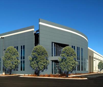
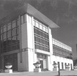
14 ARCHITECTURE - Flex Office and Research and Development Prototypical Elevation Building Entrance Half-vault building projection creates an identifiable entrance feature designed to announce entrance into the Flex Office building. Belly Band Belly band provides a horizontal emphasis, designed to distinguish individual floors. Building Materials Different concrete block textures add visual interest to the façade. Building Mass Simple building volumes composed of repetitive rectilinear forms and punched windows. Vignettes Reveal Lines Recessed reveal lines add detail to the building façade. Cornice Element Subtle cornice element and change in brick course terminates the top of the building. Building Canopy Building canopy shelters patrons from the elements. Wainscot Cap Brick masonry cap terminates the wainscot wall. Fig. A Fig. B Window Fenestration Window openings divided into individual panes by mullions, enhancing façade variety and visual interest. Recessed Windows Recessed window openings express the mass of the building. Entrance Canopy Protruding Entrance Canopy adds visual interest to the façade while sheltering patrons from the elements. Fig. 1 - Express the underlying structure of the building through the use of distinctive piers, spandrels, and recessed windows that express mass, stability, and strength. Fig. 2 - Recess windows, expressing the mass of the building. Notice the prominent lintel which spans the window opening, visually supporting the building mass above. Fig. 3 - Rest buildings on a discernible base. Notice how the stone veneer base provides a pedestal for the building to rest upon. Building Materials Brick Base anchors the building to the ground plane. Lighter stucco cladding occurs above. D-14 Flex Office Fenestration Mullions divide recessed window openings into individual panes, adding façade visual interest. 1. Create four-sided architecture characterized by all building elevations expressing variety and visual interest. 2. Create buildings composed of a discernible base, middle, and cap. 3. Express façade components in ways that help establish building scale and structure. 4. Create clearly identifiable building entrances. 5. Promote daylighting by providing ample window area, atriums, and skylights. 6. Use building materials and colors that express a sense of sophistication, permanence, and durability. Structural Bays Flex Office building divided into a series of structural bays characterized by spandrels and brick piers which frame recessed window openings. Piers Piers visually exhibit the underlying structure of the building, physically transferring the weight of the building to the ground plane. 1.0 BUILDING MASSING AND SCALE 1.1 Use smaller-scaled building modules to break-up large building masses designed to reduce the perceived scale of Flex Office and Research and Development buildings (fig. 4, 6, A, B). 1.2 Use structural bays to break-up larger building masses designed to reduce perceived building scale (fig. 1, 2, 6, A, B). 1.3 S Avoid glass boxes and unarticulated facades. Boxy and monotonous building masses that lack a sense of scale shall not be permitted. 2.0 BUILDING BASE 2.1 Rest the building on a discernible base, designed as a pedestal visually supporting the weight of the building (fig. 3, A). 2.2 S Use the following techniques to differentiate the building base from upper story facades: - Masonry pedestal with cap (fig. 3, 6, A, B). - Color material variation between the base and upper façade - Raised planters - Berming against the building (30 inches, minimum) - Window awnings and canopies - Belly bands (fig. 2, A, B) 3.0 FAÇADE ARTICULATION 3.1 Discourage weak or token expressions of structure or an inconsistent statement of structure. 3.2 Reflect the quality and integrity of the underlying structure of the façade in a clear and Research and Development Spandrels Spandrels span window openings, visually supporting the building mass above. Structural Bays Building divided into a series of structural bays characterized by piers, spandrels, and recessed window planes, creating a repetitive and rhythmic building base. Fig. 4 - Distinguish building corners through the use of tower elements that anchor corners, creating visual interest. consistent manner through the use of structural bays (fig. 1, 2, A, B). 3.3 Segment the façade into a series of structural bays composed of a column/pier, recessed window, and spandrel designed to visually segment an otherwise massive façade into a series of individual units (fig. 1, 2). 3.4 S Avoid flush building surfaces. Continuous all glass curtain walls dropped straight into the ground plane without transition shall not be permitted. 3.5 Recess windows to express building mass (fig. 1, 2, A, B). 4.0 BUILDING CAP 4.1 Crown the building with a distinguishable cap designed to terminate the top of the building (fig. 2, 4, 6, B). 4.2 S Conceal rooftop mechanical equipment. All rooftop mechanical equipment shall be contained within the pitched roof structure, completely screened within a penthouse, or hidden behind a roof parapet (fig. B). 5.0 BUILDING MATERIALS 5.1 S The following building materials shall be permitted: All material transitions shall occur at inside corners. Façades: - Concrete, poured-in-place, pre-cast, and tilt-up (sandblasted or textured) - Concrete, with light colored aggregate - Masonry, Split face concrete block - Masonry, Stone Veneer (i.e., Brownstone, Sandstone, Slate) Fig. 5 - Layer wall planes. Notice how the colonnade adds layering to the façade, creating rich shadow patterns which express depth. - Masonry, Stone (i.e., Ashler-laid, Pitched Face) - Masonry, Brick (i.e., Face Brick, FBX) - Metal (such as I-beams, Corten steel, or corrugated metal, subject to DRC review and approval) - Stucco, Smooth - Sustainable Materials are encouraged Windows: - Glass, Lightly tinted (Allowing 80 percent light transmission) - Glass, Transparent - Openable Windows are encouraged Roofs: - Metal, Standing Seam - Metal, Corten Steel - Rolled metal or rubber membrane roofing (Flat roof sections, only. Screened by a parapet wall and associated cornice). Fig. 6 - Create a distinctive roof cap. Notice how the substantial hipped roof terminates the top of the Research and Development Office building.


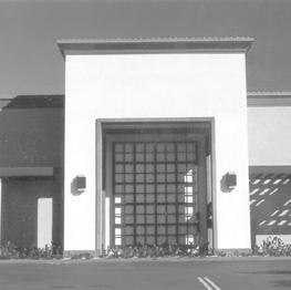
15 Vignettes Prototypical Elevation ARCHITECTURE - Light and High Bay Industrial Building Massing Simple rectilinear building masses with surface decoration, allow ample interior space for light manufacturing and warehouse/distribution facilities. Roof Form Contemporary flat roof form with parapet wall screens mechanical equipment from public view. Building Materials Building composed of textured concrete piers and lightly sandblasted concrete spandrels, creates a durable surface. The entrance pavilion is clad with metal panels. Cornice Subtle cornice element terminates the top of the building. Fig. 7 - Distinguish the building entry. Notice how the entrance tower pavilion punctuates the roofscape, functioning as an identity icon while clearly identifying the building entry. Fig. 8 - Layer building planes to increase façade variety and visual interest, creating a layered effect that adds rich shadow patterns. Fig. 9 - Use building recesses to add visual interest to façades. Notice how the distinctive, deeply set building recess, coupled with a trellis element, creates rich shadow patterns, enhancing façade variety. Entrance Pavilion Distinguishable pavilion announces entrance into the building. Notice how the projecting pavilion tower is capped by a distinctive overhanging roof form, which functions as an identity icon. Structural Bay Structural bays composed of concrete piers and in-filled spandrels create simple visual relief. Fenestration Protruding mullions divide window openings into individual windows, adding visual interest. Surface Reveal Recessed reveal lines provide surface indentations that subtly define building segments. Fig Use building projections to increase facade variety and visual interest. Notice how the building projections coupled with the cornice elements create ample facade articulation. Fig Segment building facades into a series of individual structural bays composed of piers; spandrels, and window openings. 1.0 BUILDING MASSING 1.1 Create a simple ground floor building base designed to visually anchor the building to the ground plane (fig. 10, C). 1.2 Crown the building with a distinguishable cap, designed to visually terminate the top of the building (fig. 7, 12, C). 1.3 S Distinguish the ground floor base from upper story facades. Increase ground floor height, based upon the following requirements: - Minimum Ground Floor Height: 16 Feet 2.0 ROOF FORM 2.1 Use distinguishable roof forms. Use the following roof forms to create a identifiable roof cap: - Hip (fig. 6) - Vault (fig. A) - Flat roof with a distinctive cornice (corona) (fig. 12) - Flat roof with a large protruding roof overhang (fig. 7, C) 2.2 S Conceal rooftop mechanical equipment. All rooftop mechanical equipment shall be contained within the pitched roof structure, completely screened within a penthouse, or screened by a roof parapet that harmonizes with the architectural style of the building (fig. 12, C). 3.0 BUILDING FAÇADES 3.1 Reflect the quality and integrity of the underlying structure of the façade in a clear and consistent manner through the use of structural bays (fig. 10, 12, C). 3.2 Express and distinguish both horizontal floor lines and vertical structural piers (fig. 10, C). Fig Create a distinctive cap, designed to terminate the top of the building. Notice how the distinct protruding cornice element creates a distinguishable building cap. Canopy Projecting entrance canopy shelters patrons from the elements. 3.3 Segment the building into a series of structural bays composed of a column/pier and spandrel designed to visually segment an otherwise massive façade into a series of individual units (fig. 10, 12, C). 3.4 S Discourage unarticulated architecture. Boxy and monotonous facades that lack a sense of scale shall not be permitted on sides subject to public view. 3.5 Discourage weak or token expressions of structure or an inconsistent statement of structure. 3.6 S Avoid flush building surfaces. Continuous all glass curtain walls dropped straight into the ground plane without transition shall not be permitted. 4.0 BUILDING MATERIALS 4.1 Use texture and application of color to add visual interest to an otherwise ordinary building surface. 4.2 Use material texture, color, control joints, and patterns of materials to add visual interest to building surfaces. 4.3 Avoid highly reflective surfaces that generate glare such as mirrored and reflective glass. 4.4 Avoid large, featureless building surfaces. Large all glass curtain walls are typically unacceptable unless used in combination with building structural bays that can provide a sense of scale and rhythm. 4.5 S The following building materials shall be permitted: All material transitions shall occur at inside corners. Building Base and Façades: - Concrete, poured-in-place, pre-cast, and tilt-up (sandblasted or textured) - Concrete, with light colored aggregate - Masonry, Brick (i.e., Face Brick, FBX) Ornamental Piers Ornamental masonry piers frame and enclose the entrance pavilion. - Masonry, Stone (i.e., Ashler-laid, Broken Rangework) - Masonry, Stone Veneer (i.e., Brownstone, Sandstone, Slate) - Metal (such as I-beams, Corten steel, or corrugated metal, subject to DRC review and approval) Windows: - Glass, Transparent - Glass, Lightly tinted (Allowing 80 percent light transmission) Roofs: - Metal, Standing Seam - Metal, Corten Steel - Rolled metal or rubber membrane roofing (Flat roof sections, only. Screened by a parapet wall and associated cornice (corona)). Fig. C Building Perimeter Landscaping Perimeter landscaping softens building elevations. 1. Crown buildings with a discernible building cap. 2. Create articulated building facades that provide variety and visual interest by expressing building structure. 3. Promote façade articulation by segmenting building walls into a series of individual structural bays. 4. Create a distinguishable pavilion designed to identify the building entry. 5. Use durable high-quality building materials. D-15


16 LANDSCAPE On-Site Landscaping Vignettes Trees Continuous row of trees soften the building façade. Trees Consistent soldier rows of trees soften building architecture while shading the pedestrian promenade. Hedges Hedge defines the building edge, creating a rich layer of foundation plantings. Hardscape Tinted concrete adds color and distinction to the pedestrian promenade. Seating Benches provide seating opportunities for patrons. Fig. 1 - Use trees, shrubs, and ground covers to encircle and enclose onsite detention ponds. Notice also the decorative stone retaining wall that adds visual interest. Fig. 2 - Use trellis elements and colonnades to soften building architecture. Fig. 3 - Use planters within In-Line Retail and Large Format centers to soften pedestrian promenades. Notice how the colorful annuals add life and animation to the sidewalk. Shrubs Low shrubs create a colorful border, transitioning to larger hedge masses. Raised Planters Decorative raised planters containing annual flowers and native shrubs add color and visual interest to the pedestrian promenade. Pedestrian Walkway Walkway composed of decorative exposed aggregate concrete accommodates pedestrian movements. Fig. A Fig. B Tree Grates Durable ornamental tree grates add a decorative cast iron element to the pedestrian promenade. Fig. 4 - Use landscaping to frame and enclose formal open space. Notice the consistent tree rows and hedge that define and enclose the outdoor plaza. Fig. 5 - Use landscaping to soften building architecture. Notice how the dense planting of evergreen trees buffer the building from the streetscape. Fig. 6 - Use landscape medians to segment parking fields into a series of individual parking courts. Notice the tree rows that create a defined outdoor room Create a cohesive on-site landscape design that unifies District D. Create individual sub-district landscape statements that complement and harmonize with the overall District D landscape theme. Relate formal and informal landscape patterns to land use intensity, circulation configurations, and natural features. Promote the use of on-site landscaping that provides shade, frames views, is visually interesting in winter, and softens building architecture. Create landscapes that reinforce the spatial relationships of formal open space features. Create landscape patterns that break-up large expanses of pavement. Use a consistent palette of street furniture elements to unify In-Line Retail and Large Format sites (Crossroads Boulevard Sub-Area). 1.0 GENERAL 1.1 Overall requirements for landscaping are outlined in the General Landscape Design Guidelines section. Included is a Recommended Plant List tailored to the desired landscape image for District D - The Northern District. 1.2 As a major unifying element, the Master Developer will provide the design of all streetscape and common area landscape to provide structure and consistency to the district. Individual property owners/developers will be responsible for the installation and maintenance of the landscape. 1.3 S Refer to the Millennium GDP and City of Loveland Site Planning Performance Standards and Guidelines for detailed bufferyard performance standards. 1.4 Coordinate on-site landscape design with the overall Landscape Master Plan for off-site streets and common areas. Provide a seamless transition to off-site landscape areas. 1.5 Use landscaping to soften parcel perimeter edges. Avoid harsh lines at property edges, such as abrupt changes in mulch type or plant materials placed in an obvious line. 1.6 Use landscaping to soften Right-of-Way edges. Provide a gradual transition of trees, shrubs, and ground covers designed to harmonize with off-site landscaping. 1.7 Soften building facades visible from public areas or high use areas with trees, shrubs, and ground covers (fig. A). 1.8 Locate plant materials to shelter buildings and formal open spaces from winter winds, allowing solar exposure in the winter, and provide summer shade (fig. 4). 1.9 Use ornamental accent landscaping at site entrances designed to announce entrance Create formal landscape patterns to frame and enclose pedestrian plazas and forecourts (fig. 4) Use plant containers and raised planters at building entrances, along pedestrian promenades, and within plazas to add annual color (fig. 2, 3) Create landscape medians and islands to break-up large expanses of pavement (fig. 6, 7, 8, 9) Use plant materials to create sheltered outdoor areas, designed to accommodate pedestrian gatherings (fig. 4) S Group plants with similar water requirements together. 2.0 I-25 CORRIDOR SUB AREA: OFFICE AND AUTO DEALERSHIPS 2.1 Accentuate office entries and auto dealership staging areas with enhanced hardscape elements and formal tree plantings in tree grates. 2.2 Create clustered perimeter landscape treatments designed to allow visual penetration to auto dealership display pads. 2.3 Use perimeter building landscaping to soften office and auto dealership architecture (fig. A). 3.0 CROSSROADS BOULEVARD SUB-AREA: IN-LINE RETAIL AND LARGE FORMAT RETAIL 3.1 Create formal soldier rows of trees to accent linear pedestrian promenades (fig. 3, B). 3.2 Use tree grates and guards to accommodate formal tree plantings along pedestrian promenades and within plazas (fig. B). 3.3 Arrange plant materials to harmonize with the architectural style of In-Line and Large Format Retail establishments, accenting pedestrian promenades, softening facades, and screening nuisances (fig. B). 3.4 Use landscaping to soften In-Line and Large Format architecture, reducing the perceived scale of these large commercial buildings (fig. 5). 3.5 Create a substantial landscape buffer adjacent to the Interstate 25 corridor, designed to soften Large Format architecture while maintaining building identity and visibility. 3.6 Use a consistent palette of street furniture elements, including pedestrian lighting, tree grates, tree guards, trench drains, seating, trash receptacles, and bicycle racks designed to unify In-Line Retail and Large Format sites. 4.0 ROCKY MOUNTAIN AVENUE SUB-AREA: FLEX OFFICE AND RESEARCH AND DEVELOPMENT 4.1 Provide ample building perimeter landscaping designed to soften building facades (fig. A). 4.2 Use landscaped trellis elements and colonnades designed to soften building architecture while creating continuous covered pedestrian walkways (fig. 2). 4.3 Use trees to frame and enclose meaningful formal open space such as pedestrian forecourts and plazas (fig. 4). 4.4 Use trees, shrubs, and ground covers to encircle and enclose on-site detention ponds, creating a pedestrian-oriented amenity, connected to pedestrian systems (fig. 1). 5.0 INTERNAL CORE SUB-AREA: LIGHT AND HIGH BAY INDUSTRIAL 5.1 Provide ample building perimeter landscaping designed to soften building facades (fig. A). 5.2 Use trees to frame and enclose meaningful formal open space such as pedestrian forecourts (fig. 4). 5.3 Use trees, shrubs, and ground covers to encircle and enclose on-site detention ponds, creating a pedestrian-oriented amenity. 5.4 Use screen walls with landscaping designed to screen distribution, service, delivery and outdoor storage areas. D-16


 - Maximum Illumination: 4,800 Lumens Seating:")
17 Vignettes In-Line and Big Box Retail - Conceptual Street Furniture Palette STREET FURNITURE Pedestrian Lighting Noral - Cato Pedestrian Lighting Sternberg Lighting - Gallery Seating Du Mor, Inc. - Bench 118 Seating Timberform Fig. 7 - Use parking lot landscape islands to break-up large expanses of pavement. Notice the canopystyle trees that provide ample shade. Fig. 8 - Use tree rows to segment large parking fields into outdoor rooms. Notice how the windrow style plantings break-up large expanses of pavement. Fig. 9 - Use landscape islands at the ends of parking aisles to define the parking field. Notice how the ground plane includes flowering plants. Pedestrian Lighting Devine Lighting - BCR161 Pedestrian Lighting Western Lighting - FXH322 Tree Grate Urban Accessories - Title-24 Fig Use outdoor chairs and tables to accommodate employee lunchtime activities (Keystone Ridge Pullman Courtyard series). Fig Use plant containers within forecourts, plazas, and along pedestrian promenades to add animation and color. Fig Provide round hockey puck luminaries within parking lots, designed to direct light downward (Kim Lighting CC/CCS Series). Trench Drain Urban Accessories - Angle Bike Rack BRP Enterprises - WA2-11-SM-SF Trash Receptacle Wabash Valley - LRB32F Tree Guard Wabash Valley - TG1 Seating (Rocky Mountain and Internal Core Sub-Areas) BRP Enterprises - PA301-PF 6.0 STREET FURNITURE 6.1 Use decorative street furniture to unify the District. Street furniture shall have a discernible base, shaft, and capital that supports the luminary. 6.2 Provide decorative street furniture. Street furniture shall be provided, based upon the following guidelines: Pedestrian Lighting: - Location: Plazas and pedestrian walkways - Style: Noral - Cato Sternberg Lighting - Gallery Devine Lighting - BCR161 Western Lighting - FXH322 - Color: TBD - Height: feet (maximum) - Maximum Illumination: 4,800 Lumens Seating: - Du Mor Inc. - Bench Timberform BRP Enterprises - PA301-PF Trash Receptacles: - Wabash Valley - LBR32F Tree Grates: - Urban Accessories - Title-24 Tree Guards: - Wabash Valley - TG1 Trench Drains: - Urban Accessories - Angle Bike Racks: - BRP Enterprises - WA2-11-SM-SF D-17
DISTRICT E - The East District
 E-3 E-4 E-5 E-6 E-8 E-10 E-12 E-14 E-15 E-16 E-18 E-19 E-20. Location Map and District Description. District Image. Site Planning - Lifestyle Center and Regional Retail. Site Planning - Mixed Use and Town
Walnut Creek Transit Village Design Guidelines. Part Three III - 25
 C. General Design Criteria Part Three DRAFT 0/6/ III - 5 Frontage Types Frontage is a semi-public transition zone at the ground level where public and private realms meet. An understanding of various frontage
4. INDUSTRIAL 53 CASTLE ROCK DESIGN
 4. INDUSTRIAL 53 CASTLE ROCK DESIGN CASTLE ROCK DESIGN 54 4. INDUSTRIAL Overview Well-designed and attractive industrial centers are the product of blending economic realities with both functional and
Buildings may be set back to create small plazas provided that these setbacks do not substantially disrupt the street wall s continuity.
 6-22 Community Design Street Walls and Street-front Setbacks The siting of buildings will play a critical role in establishing the character and sense of place for the District. Siting buildings at the
Commercial Development Permit Area
 City of Kamloops KAMPLAN Commercial Development Permit Area PURPOSE The purpose of this Development Permit Area (DPA) is to establish objectives and provide guidelines for the form and character of commercial
SECTION TWO: Overall Design Guidelines
 SECTION TWO: Overall Design Guidelines This section provides overall design principles and guidelines for the Gardnerville Mixed-use Overlay. They provide criteria for mixed-use places consisting of residential,
4.0 Design Guidelines For The Village Centre. South fields Community Architectural Design Guidelines Town of Caledon
 4.0 Design Guidelines For The Village Centre 4.0 Design Guidelines for the Village Centre The Village Centre is the focal point of the entire South Fields Community and is designed as a traditional commercial
Site Planning. 1.0 Site Context. 2.0 Pedestrian Circulation Systems. Pag e 2-23
 The following photographs from throughout the country illustrate key urban design principles. Photographs are provided to illustrate the overall urban design concepts described in Chapter 1 of the Downtown
WINDSOR GLEN DESIGN GUIDELINES
 WINDSOR GLEN DESIGN GUIDELINES Adopted by Council, 2006 WINDSOR GLEN REDEVELOPMENT DESIGN GUIDELINES August 2006 1.0 Master Plan Organization For this area of the Coquitlam Town Centre, a mix of high,
This chapter contains the design standards and guidelines for development and improvement of office and industrial buildings and
 CHAPTER 4: INDUSTRIAL AND OFFICE This chapter contains the design standards and guidelines for development and improvement of office and industrial buildings and projects. Applicants should discuss specific
Resolution : Exhibit A. Downtown District Design Guidelines March 2003
 Resolution 03-011: Exhibit A Downtown District Design Guidelines March 2003 DOWNTOWN DISTRICT DESIGN GUIDELINES CITY OF SOUTHLAKE, TEXAS Adopted March 2003 1 DOWNTOWN DISTRICT DESIGN GUIDELINES Adopted
Design Guidelines Checklist
 Design Guidelines Checklist A quick reference to the City of Vista Design Guidelines City of Vista Community Development Department Planning Division 600 Eucalyptus Avenue Vista, CA 92084 760.639.6100
COMMERCIAL & INDUSTRIAL DESIGN GUIDELINES CITY OF RANCHO CUCAMONGA PLANNING DIVISION
 COMMERCIAL & INDUSTRIAL DESIGN GUIDELINES CITY OF RANCHO CUCAMONGA PLANNING DIVISION INTRODUCTION These guidelines were prepared in response to the needs of many users: developers, property owners, architects,
Chapter 11. Industrial Design Guidelines 11.1 INTRODUCTION AND PURPOSE 11.3 SITE PLANNING GUIDELINES 11.2 GENERAL DESIGN OBJECTIVES
 Chapter 11 Industrial Design Guidelines 11.1 INTRODUCTION AND PURPOSE The following industrial/design guidelines seek to assure high quality development in Santa Ana s industrial districts by: The design
13. New Construction. Context & Character
 13. New Construction Context & Character While historic districts convey a sense of time and place which is retained through the preservation of historic buildings and relationships, these areas continue
Chapter 4: Jordan Road Character District
 4: Jordan Road Character District 4.1 Introduction The Jordan Road character district encompasses much of the former Jordan orchard and farmstead, which was a significant part of Sedona s history. The
lot flankage Y street 16m 6m landscape strip for large site 3m landscape strip for small medium site
 Commercial General Commercial Objectives Create developments compatible with adjacent land uses in scale, function and character Define a consistent and attractive street edge with quality landscaping,
WATERFRONT DISTRICT DESIGN STANDARDS
 WATERFRONT DISTRICT DESIGN STANDARDS 20.25.080 WATERFRONT DISTRICT A. Purpose. This section is intended to implement The Waterfront District Subarea Plan by: 1. Creating a safe, vibrant mixed-use urban
AIRPORT BUSINESS PARK
 PIER MAC PETROLEUM INSTALLATION LTD. AIRPORT BUSINESS PARK DEVELOPMENT APPLICATIONS March 2003 4.1 Airport Business Park Development Permit Area 4.1.1 Justification/Design Concept The design concept envisioned
DEVELOPMENT DESIGN GUIDELINES
 DEVELOPMENT DESIGN GUIDELINES Approved by Surrey City Council January 26, 2004 Campbell Heights Business Park - Development Design Guidelines TABLE OF CONTENTS 1.0 DEVELOPMENT CONCEPT... 1 2.0 DESIGN OBJECTIVES...
PROPOSED WATERFRONT DISTRICT DESIGN STANDARDS
 PROPOSED WATERFRONT DISTRICT DESIGN STANDARDS 20.25 DESIGN REVIEW. 20.25.080 WATERFRONT DISTRICT A. Purpose. This section is intended to implement The Waterfront District Subarea Plan by: 1. Creating a
City of Redlands Architectural Guidelines for Non-Residential Development
 14. Building articulation shall be included in the design of building, in order to create a formal entry statement. Avoid this Do this Page 11 15. Give special attention to creating pedestrian scale and
Urban Design Brief December 23, 2015 Southside Construction Group Official Plan & Zoning By-Law Amendment
 Urban Design Brief Proposed Official Plan & Zoning By-Law Amendment 3244, 3263 and 3274 Wonderland Road South Southside Group December 23, 2015 TABLE OF CONTENTS Page No. INTRODUCTION... 1 SECTION 1 LAND
VILLAGE OF SKOKIE Design Guidelines for Mixed-Use Districts NX Neighborhood Mixed-Use TX Transit Mixed-Use CX Core Mixed-Use
 VILLAGE OF SKOKIE Design Guidelines for Mixed-Use Districts NX Neighborhood Mixed-Use TX Transit Mixed-Use CX Core Mixed-Use TABLE OF CONTENTS CHAPTER 1 SITE DESIGN Purpose 1 CHAPTER 2 SITE DESIGN Streetscape
Design Guidelines and Development Standards for Southwood Ranch. Prepared February, 2016 by
 Design Guidelines and Development Standards for Southwood Ranch D e s i g n D i s t r i c t Prepared February, 2016 by Table of Contents Introduction 2 District Overlay Map. 3 Development Standards. 4
ATTACHMENT A. SILVERDALE DESIGN STANDARDS Amendments to the Waaga Way Town Center Chapter
 ATTACHMENT A SILVERDALE DESIGN STANDARDS Amendments to the Waaga Way Town Center Chapter Chapter 10. Waaga Way Town Center 10.1 Physical Identity Elements & Opportunities The Waaga Way Town Center includes
Community Design Plan
 Gardena General Plan 2006 Authority While the is not a required element of a General Plan, it is included because improving the community appearance and image is paramount to the overall quality of life
The Village. Chapter 3. Mixed Use Development Plan SPECIFIC PLAN
 The Village SPECIFIC PLAN Chapter 3 3.1 INTRODUCTION 3.1.1 Purpose This Chapter describes the development regulations applicable to the Mixed-Use and Transit Center Planning Areas. These form-based regulations
ELK GROVE TOWN CENTER DESIGN GUIDELINES
 ......... ELK GROVE TOWN CENTER DESIGN GUIDELINES LAGUNA RIDGE SPECIFIC PLAN... June 2008 ............ DESIGN GUIDELINES Table of Contents Contents Section A: Town Center Overview...1 A.1. Purpose and
B L A C K D I A M O N D D E S I G N G U I D E L I N E S for Multi-family Development
 B L A C K D I A M O N D D E S I G N G U I D E L I N E S for Multi-family Development Adopted June 18, 2009 This section of the Design and focuses on site planning and design guidance for new multi-family
4.9 Mendocino Avenue Corridor Plan Design Guidelines
 4.9 Mendocino Avenue Corridor Plan Design Guidelines The Mendocino Avenue Corridor Plan addresses the area between College Avenue and Steele Lane. Mendocino Avenue is a busy arterial that runs parallel
CHAPTER 3. Design Standards for Business, Commercial, Industrial, Recreational and Institutional Uses
 CHAPTER 3 Design Standards for Business, Commercial, Section Number Title Ordinance Number Date of Ordinance 16-3-1 Applicability 2006-11 2008-04 07-01-08 16-3-2 Uniform Standards for Architectural Design
1. General Purpose. 3. Uses
 1. General Purpose The purpose of this DC1 Provision is to facilitate the development of a pedestrian friendly Community Commercial Centre that may accommodate a range of commercial, residential, office,
Cha p t e r 2: Ge n e r a l De s i g n Gu i d e l i n e s
 Downtown Ann Arbor Design Guidelines Cha p t e r 2: Ge n e r a l De s i g n Gu i d e l i n e s This chapter presents general design guidelines for new site plan or PUD projects in downtown Ann Arbor. The
INSTITUTIONAL USE DESIGN COMPATIBILITY TECHNIQUES
 INSTITUTIONAL USE DESIGN COMPATIBILITY TECHNIQUES INTRODUCTION Community institutions are an important part of the character and vitality of neighborhoods in Forsyth County. Institutional uses include
Policies and Code Intent Sections Related to Town Center
 Policies and Code Intent Sections Related to Town Center The Town Center Vision is scattered throughout the Comprehensive Plan, development code and the 1994 Town Center Plan. What follows are sections
PUBLIC RIGHT-OF-WAY IN THIS CHAPTER PUBLIC REALM
 PUBLIC RIGHT-OF-WAY This section provides design guidelines for improvements in the public right-of-way. The public right-of-way refers to streets, sidewalks, non-vehicular thoroughfares, parks and greenways
general corridor design guidelines gen-0.0
 general corridor design guidelines gen-0.0 facades gen-1.0 GEN-1.1: TRANSPARENCY GEN-1.1.1: WALL OPENINGS In order to create buildings that are visually interesting for passers-by, blank ground floor
5.7 Design Criteria for the Private Realm Organization of Private Realm Design Standards and Guidelines Guidelines vs.
 5.7 Design Criteria for the Private Realm The Private Realm (shown in Exhibit 5.7a) includes the privately owned property not included in the Setback Realm described in the previous section. It encompasses
Future Five. Design/ Development Guidelines. January 2008 Amended June 08 per City Council motion
 Future Five Design/ Development Guidelines January 2008 Amended June 08 per City Council motion 5-Points Design Guidelines Table of Contents I. Introduction 3 II. Area boundaries 4 III. Review Process
Greater East Wenatchee Urban Growth Area. Design Standards & Guidelines
 Greater East Wenatchee Urban Growth Area Design Standards & Guidelines November 30, 2006 Table of Contents General Guidelines for All Development Site Design - - - - - - - - - - - - - - - - - - - - - -
MULTIFAMILY RESIDENTIAL DESIGN PRINCIPLES Site Plan and Design Review Principles Checklist
 MULTIFAMILY RESIDENTIAL DESIGN PRINCIPLES Site Plan and Design Review Principles Checklist Applicant s Name: Project Address: Phone: Email: Applicant shall fill out the design guidelines checklist for
DEVELOPMENT CONTROLS MEDICAL DISTRICT
 6.01. GENERAL DESIGN GUIDELINES A. Site Planning B. Architectural Design C. Medical Facility Signage & Lighting D. Exhibit 48. ARCHITECTURAL DESIGN CONCEPTS 6.02. MEDICAL FACILITY STANDARDS & GUIDELINES
Appendix A COMMUNITY IMPROVEMENT PLAN DESIGN GUIDELINES
 Appendix A COMMUNITY IMPROVEMENT PLAN DESIGN GUIDELINES INTRODUCTION The continuous and desirable improvement of Arnprior requires a clear understanding of what is envisioned for the Town. These Design
Building and Site Design Standards
 Commercial Design Standards All Business and Industrial Uses as Described in Section 2234 Requiring Special Permit Review Except Large-Scale Ground Mounted Solar Photovoltaic Installations and Wireless
ZONING. 300 Attachment 1. City of Oneonta. Design Guidelines ( )
") 300 Attachment 1 City of Oneonta Design Guidelines ( 300-68) A. Site Organization. These guidelines address issues related to both building and parking location. Other issues include vehicle access (curb
300 Attachment 1 City of Oneonta Design Guidelines ( 300-68) A. Site Organization. These guidelines address issues related to both building and parking location. Other issues include vehicle access (curb
1. Avoid extensive blank walls that would detract from the experience and appearance of an active streetscape.
 08 ARCHITECTURAL DETAIL Once a building s massing and street wall have been defined, architectural details, including façade variation, materials and window treatment, shape a building s visual identity.
B. Blocks, Buildings and Street Networks
 B. Blocks, Buildings and Street Networks Figure IV.4 A rational block pattern with connected streets Introduction The single most important element in the physical and functional integration of mixed use
R STREET CORRIDOR NEIGHBORHOOD Site Plan and Design Review Supplemental Guidelines Checklist
 R STREET CORRIDOR NEIGHBORHOOD Site Plan and Design Review Supplemental Guidelines Checklist Applicant s Name: Project Address: Phone: Email: Applicant shall fill out the design guidelines checklist for
Design Guidelines. Roosevelt. Mike Podowski DPD Design Guidelines Ordinance ATT 13 August 13, 2012 Version #1
 Roosevelt Design Guidelines The Roosevelt Neighborhood Design Guidelines apply within the Neighborhood Boundary. Map 1 2 Map 2 3 Map 3 4 CS1 Natural Systems and Site Features Citywide Guideline: Use natural
Urban Design Manual 2.0 DRIVE-THROUGH FACILITIES. Background. Urban Design Challenges
 222221 2.0 DRIVE-THROUGH FACILITIES Background In recent years, drive-through facilities have grown significantly in popularity with drive-through restaurants, in particular, being established on numerous
CENTERS AND CORRIDORS
 INITIAL DESIGN STANDARDS AND GUIDELINES for CENTERS AND CORRIDORS City of Spokane Planning Services Third Floor, City Hall 808 W. Spokane Falls Blvd. Spokane, WA 99201-3329 (509) 625-6300 www.spokaneplanning.org
Division 9 Southwood Ranch (CR 484/475/475A Corridor-Gateway Development Overlay) Purpose and Intent Applicability.
 Purpose and Intent Applicability.") Division 9 Southwood Ranch (CR 484/475/475A Corridor-Gateway Development Overlay) 5.9.1 Purpose and Intent. The Southwood Ranch Overlay is intended to be a mixed use community with commercial and residential
Division 9 Southwood Ranch (CR 484/475/475A Corridor-Gateway Development Overlay) 5.9.1 Purpose and Intent. The Southwood Ranch Overlay is intended to be a mixed use community with commercial and residential
VILLAGE OF HUNTLEY COMMERCIAL DESIGN GUIDELINES
 VILLAGE OF HUNTLEY COMMERCIAL Village of Huntley Development Services Department Planning & Zoning Division 10987 Main Street Huntley, Illinois 60142 (847) 515-5252 www.huntley.il.us VILLAGE OF HUNTLEY
LITTLETON CENTER DESIGN GUIDELINES
 LITTLETON CENTER DESIGN GUIDELINES Littleton Center Design Guidelines 1 I. DESIGN REVIEW PROCESS These Design Guidelines have been initially created by Hallin Family LLC (the "Developer"), and govern all
Chapter 5: Mixed Use Neighborhood Character District
 5: Mixed Use Neighborhood Character District 5.1 Introduction The Mixed Use Neighborhood character district acts as a transition or bridge between the State Route 89A District s commercial area to the
appendix and street interface guidelines
 appendix five: building and street interface guidelines appendix 5 building and street interface guidelines BOULEVARDS Boulevards are generally characterized by higher levels of traffic movement at higher
CHAPTER FIVE COMMUNITY DESIGN
 CHAPTER FIVE COMMUNITY DESIGN CHAPTER FIVE - COMMUNITY DESIGN Assumptions Frazier Park and Lebec have historically developed according to different patterns of spatial form. While both communities are
FREEWAY/TOURIST DISTRICT
 FREEWAY/TOURIST DISTRICT DESIGN STANDARDS FOR THE CITY OF MOUNTLAKE TERRACE March, 2014 MOUNTLAKE TERRACE FREEWAY/TOURIST DESIGN STANDARDS March, 2014 1 TABLE OF CONTENTS Introduction...1 Design Site Design
VEHICULAR AND PEDESTRIAN CIRCULATION
 This perspective sketch communicates the intended character and quality of a proposed streetscape design. Locate benches near a major intersection where people tend to gather. Seating and lighting provide
D. Landscape Design. 1. Coverage Intent: To provide adequate landscaping materials that enhance the appearance of development projects.
 D. Landscape Design The standards and guidelines in this section give design guidance for the landscaping components of industrial and office projects. City regulations require that all landscaping be
Community Mixed Use Zone Districts (CMU)
") 18.28.500 Community Mixed Use Zone Districts (CMU) The Community Mixed Use Zone Districts (CMU) are intended to help implement the land use goals and strategies found in the Golden Vision 2030 values,
18.28.500 Community Mixed Use Zone Districts (CMU) The Community Mixed Use Zone Districts (CMU) are intended to help implement the land use goals and strategies found in the Golden Vision 2030 values,
A. OVERVIEW, GOALS, AND GUIDELINES III - 1 PART THREE FINAL 02/20/13 WALNUT CREEK TRANSIT VILLAGE DESIGN GUIDELINES
 A. OVERVIEW, GOALS, AND GUIDELINES III - OVERVIEW, GOALS, AND GUIDELINES OVERVIEW The Walnut Creek Transit Village Design Guidelines for the Private Realm addresses site-specific urban design recommendations,
Urban Design Brief Fanshawe Park Road. Competition Toyota
 Urban Design Brief 1300 Fanshawe Park Road Competition Toyota May 2, 2014 TABLE OF CONTENTS Page No. INTRODUCTION... 1 SECTION 1 LAND USE PLANNING CONTEXT... 1 1.1 The Subject Lands... 1 1.2 The Proposal...
3.13. Development Guidelines
 3.3 Landscaping Elements Landscaping should be used to frame and soften structures, define site functions, enhance the quality of the environment, and screen undesirable views. Safety, environmental impacts,
Prepared by: LCT Design Group, LLC 401 North Franklin Street, Suite 5S Chicago, Illinois 60610
 Prepared by: LCT Design Group, LLC 401 North Franklin Street, Suite 5S Chicago, Illinois 60610 Existing Conditions Residential Guidelines Future Land Use -East Study Area - West Study Area Existing Conditions
3.4 Business & Light Industrial Parks and Buildings
 3.4 Business & Light Industrial Parks and Buildings I. GOALS A. To encourage superior design in business and light industrial parks. Section 3.4 - Business & Light Industrial Parks and Buildings B. To
Town of White Springs Design Standards
 Town of White Springs Design Standards Community Design Community design is an important consideration in determining future land use and development. The form that development takes influences property
Division VI Community Mixed Use (CMU) Architectural Guidelines and Standards
 Architectural Guidelines and Standards") Division VI 18.40.800 Community Mixed Use (CMU) Architectural Guidelines and Standards 18.40.810 Guidelines The goals of the Comprehensive Plan include a focus on pedestrian safety, amenities and aesthetics
Division VI 18.40.800 Community Mixed Use (CMU) Architectural Guidelines and Standards 18.40.810 Guidelines The goals of the Comprehensive Plan include a focus on pedestrian safety, amenities and aesthetics
WEST LOOP DESIGN GUIDELINES CHECKLIST
 WEST LOOP DESIGN GUIDELINES CHECKLIST Section 1.0 General Strategies 1.1 DESIGN EXCELLENCE: ENCOURAGE HIGH QUALITY AND INNOVATIVE DESIGN OF NEW BUILDINGS WITHIN THE WEST LOOP WITHOUT BEING PRESCRIPTIVE
Clairtrell Area Context Plan
 Clairtrell Area Context Plan March 2005 Urban Development Services City Planning Contents 1. Introduction... 4 2. Development Structure... 6 2.1 Streets... 7 2.1.1 Sheppard Avenue and Bayview Avenue...
Design Guidelines for Multi-Family Residential Development
 Design Guidelines for Multi-Family Residential Development Development Services 972-466-3225 cityofcarrollton.com September 2012 Table of Contents Purpose... 1 Design Objectives... 2 Building Design Guidelines...
Gas Stations ottawa.ca
 Urban Design Guidelines for Gas Stations ottawa.ca Ce document est disponible en français sur ottawa.ca. This document is available in French on ottawa.ca. Approved by City Council May 24, 2006 City of
VILLAGE OF CHANNAHON COMMERCIAL DESIGN GUIDELINES. Village of Channahon S. Navajo Drive Channahon, IL (815)
") VILLAGE OF CHANNAHON COMMERCIAL DESIGN GUIDELINES Village of Channahon 24555 S. Navajo Drive Channahon, IL 60410 (815) 467-6644 www.channahon.org Adopted March 6, 2006 VILLAGE OF CHANNAHON COMMERCIAL DESIGN
VILLAGE OF CHANNAHON COMMERCIAL DESIGN GUIDELINES Village of Channahon 24555 S. Navajo Drive Channahon, IL 60410 (815) 467-6644 www.channahon.org Adopted March 6, 2006 VILLAGE OF CHANNAHON COMMERCIAL DESIGN
Multi family Residential Development Permit Area
 City of Kamloops KAMPLAN Multi family Residential Development Permit Area PURPOSE The purpose of this Development Permit Area (DPA) is to establish objectives and provide guidelines for the form and character
TOWN CENTER DESIGN STANDARDS FOR THE CITY OF. August, MOUNTLAKE TERRACE TOWN CENTER DESIGN STANDARDS August,
 TOWN CENTER DESIGN STANDARDS FOR THE CITY OF MOUNTLAKE TERRACE August, 2008 MOUNTLAKE TERRACE TOWN CENTER DESIGN STANDARDS August, 2008 1 TABLE OF CONTENTS Introduction...3 Design Site Design...4 Pedestrian
MIXED-USE ZONING DISTRICT DESIGN GUIDELINES
 MIXED-USE ZONING DISTRICT DESIGN GUIDELINES In addition to the development regulations contained in the Mixed-Use Zoning District, design guidelines are presented here to provide an added level of definition
Wide asphalt driveway abutting school property. garage built with incompatible materials, too close to park. incompatible fencing materials
 Wide asphalt driveway abutting school property incompatible fencing materials garage built with incompatible materials, too close to park Lack of plantings as a buffer between private property and open
Corridor Identity. Section 9. Introduction. Corridor Guiding Principles
 Corridor Identity An attractive and healthy community is a critical element of a quality place, and the design of quality places is a balance between environmental, economic, and social considerations.
Chapter PEDESTRIAN COMMERCIAL (PC) ZONING DISTRICT
 ZONING DISTRICT") Chapter 11-17 PEDESTRIAN COMMERCIAL (PC) ZONING DISTRICT Sections: 11-17-01 GENERAL PURPOSE 11-17-02 PERMITTED BUILDING TYPES 11-17-03 USES PERMITTED WITH DESIGN REVIEW 11-17-04 USES PERMITTED BY CONDITIONAL
Chapter 11-17 PEDESTRIAN COMMERCIAL (PC) ZONING DISTRICT Sections: 11-17-01 GENERAL PURPOSE 11-17-02 PERMITTED BUILDING TYPES 11-17-03 USES PERMITTED WITH DESIGN REVIEW 11-17-04 USES PERMITTED BY CONDITIONAL
built form design guidelines
 built form design guidelines Derry Green Corporate Business Park 17 built form design guidelines.1 Built Form Design Guidelines Section : Built Form Design Guidelines is intended to be used by both developers
The open space system should provide connective elements, relate to natural resources, and enhance the suburban character of the landscape..
 The open space system should provide connective elements, relate to natural resources, and enhance the suburban character of the landscape.. Mixed-use and infill development should maintain or enhance
APPENDIX A BIG BOX RETAIL DESIGN STANDARDS
 APPENDIX A BIG BOX RETAIL DESIGN STANDARDS I. Procedure The following guidelines are intended to be used as a design aid by developers proposing large retail developments and as an evaluation tool by the
5.1 Site Plan Guidelines
 5. Community Core Guidelines Development of the Community Core will take place by plan of subdivision and site plan approval. It will occur in a phased manner that will reflect the timing of residential
GUIDING PRINCIPLES IN THIS CHAPTER
 GUIDING PRINCIPLES The guiding principles and design concepts in this chapter work together with the Chapel Hill 2020 Comprehensive Plan to support new public places that can be enjoyed by all while also
FRUITVALE TRANSIT VILLAGE (Phase 2) Residential Project
 Residential Project") FRUITVALE TRANSIT VILLAGE (Phase 2) Residential Project DEVELOPER: SIGNATURE PROPERTIES ARCHITECT: HKIT ARCHITECTS April 23, 2010 TABLE OF CONTENTS 3 Vision 4 Description of Site 5 Guiding Concepts 6
FRUITVALE TRANSIT VILLAGE (Phase 2) Residential Project DEVELOPER: SIGNATURE PROPERTIES ARCHITECT: HKIT ARCHITECTS April 23, 2010 TABLE OF CONTENTS 3 Vision 4 Description of Site 5 Guiding Concepts 6
Industrial Development Permit Area
 Industrial Development Permit Area PURPOSE The purpose of this Development Permit Area (DPA) is to establish objectives and provide guidelines for the form and character of industrial development in the
FLORIN ROAD CORRIDOR Site Plan and Design Review Guidelines Checklist
 FLORIN ROAD CORRIDOR Site Plan and Design Review Guidelines Checklist Applicant s Name: Project Address: Phone: Email: Applicant shall fill out the design guidelines checklist for all guidelines applicable
Revitalization Guidelines for Corridors, Villages and Town Centres
 Revitalization Guidelines for Corridors, Villages and Town Centres July 2017 Updated May, 2018 Publishing Information Title: Prepared by: Revitalization Guidelines for Corridors, Villages and Town Centres
Design Guidelines for Commercial Development
 Design Guidelines for Commercial Development Development Services 972-466-3225 cityofcarrollton.com Table of Contents Purpose...1 Design Objectives...2 Intent...3 Building Design Guidelines...4 Materials...5
Urban Design Guidelines Townhouse and Apartment Built Form
 Urban Design Guidelines Townhouse and Apartment Built Form Town of Wasaga Beach Table of Contents 1. Introduction 1.1. Purpose 1.2. Urban Design Principles 1.3. Application of Guidelines 2. Site Design,
Town Center Design Guidelines
 Adopted by City Council on September 18, 2018 Design Theme The Draper Town Center Design Theme is defined as encompassing those architectural design styles that were prevalent in the construction of civic
New-Cast Mixed-use Development Proposal King Street West, Newcastle, Ontario
 URBAN DESIGN BRIEF New-Cast Mixed-use Development Proposal King Street West, Newcastle, Ontario TABLE OF CONTENTS: 1.0 Executive Summary 2.0 Creating Vibrant and Sustainable Urban Places: Excerpts from
Highland Village Green Design Guidelines
 Highland Village Green Design Guidelines Publishing Information Title Highland Village Green Design Guidelins Author The City of Calgary Status DRAFT - Proposed document subject to changes Additional Copies
Light Industrial Area Design Guidelines
 Table of Contents Light Industrial Area Design Guidelines Introduction...2 Vision...2 Area Character...2 Site Design...2 Interface with Residential Uses...3 Parking and Circulation...3 Parking Structures...4
Bel-Air Lexus Automobile Service Station
 Bel-Air Lexus Automobile Service Station Design Brief 443-447 McArthur Avenue Ottawa April 30, 2015 14-1299-MCA Site Details Application: Site Plan Control Legal Description and Municipal Addresses: 443
Town of Essex Urban Design Guidelines for Downtown Harrow and Essex Centre May 2014
 Town of Essex Urban Design Guidelines for Downtown Harrow and Essex Centre May 2014 1 Table of Contents Section 1.0 Purpose and Intent.3 Section 2.0 Streetscapes 4 Section 3.0 Active and Inviting Streetscapes..5
PLANNING AND DESIGN GUIDELINES FOR BLOCK C OF THE MT. DIABLO REDEVELOPMENT PROJECT AREA Adopted by Design Review Commission February 4, 2004
 PLANNING AND DESIGN GUIDELINES FOR BLOCK C OF THE MT. DIABLO REDEVELOPMENT PROJECT AREA Adopted by Design Review Commission February 4, 2004 The Walnut Creek Redevelopment Agency has an adopted plan for
T O W N O F A J A X URBAN DESIGN GUIDELINES FOR MOTOR VEHICLE GAS BARS / SERVICE CENTRES
 T O W N O F A J A X URBAN DESIGN GUIDELINES FOR MOTOR VEHICLE GAS BARS / SERVICE CENTRES June 2006 Table of Contents TABLE OF CONTENTS... 1 1.0 INTRODUCTION... 2 1.1 Purpose... 2 1.2 Organization of the...
SECTION 24 DESIGN GUIDELINES FOR LARGE COMMERCIAL AND RETAIL DEVELOPMENTS INTRODUCTION & PROCEDURE 24-2
 1 SECTION 24 DESIGN GUIDELINES FOR LARGE COMMERCIAL AND RETAIL DEVELOPMENTS INTRODUCTION & PROCEDURE 24-2 Page # ARTICLE I. SITE DESIGN AND RELATIONSHIP TO COMMUNITY 1. Site Design 24-3 2. Multiple Stores/Structures