Fan Drive Maintenance Training Manual
|
|
|
- Leon Daniel
- 5 years ago
- Views:
Transcription

1 Fan Drive Maintenance Training Manual
2 TABLE OF CONTENTS INTRODUCTION... 2 General Information... 2 LESSON 1: FAN DRIVE SYSTEM Operation Control System... 4 LESSON 2: CONTROL COMPONENTS Engine Coolant Thermal Switch Refrigerant Pressure Switch Solenoid Valve... 6 LESSON 3: ELECTRICAL CONTROL SYSTEMS (ECM) Electronic Control Module Sensors... 8 LESSON 4: ELECTRICAL CONTROL SYSTEMS (NON-ECM) Types of Electrical Control Systems Normally-Open Electrical Controls Normally-Closed Electrical Controls Comparison - Open/Closed Electrical Controls Summary LAB ACTIVITY - FAN DRIVE CONTROL COMPONENTS REVIEW QUESTIONS - FAN DRIVE CONTROL SYSTEM Review Answers - Fan Drive Control System PRIOR TO SERVICING LESSON 5: DRIVEMASTER PARTS AND REPAIR KITS Parts Identification Repair Kits DriveMaster Seal Kit DriveMaster Super Kit DriveMaster PolarExtreme Super Kit DriveMaster Friction Disc Kit DriveMaster Friction Liner Kit LESSON 6: REMOVING THE FAN DRIVE LESSON 7: DISASSEMBLING THE FAN DRIVE Tools Required Disassembly Fan Mounting Disc Removal and Inspection Spring Housing / Piston Assembly Removal Air Chamber Seals Sheave and Sheave Bearings Air Cartridge Removal LESSON 8: REBUILDING THE FAN DRIVE Torque Specifications Rebuilding Sheave Bearing Replacement Air Cartridge Spring Housing / Piston Assembly Reassembly Fan Mounting Disc Reassembly LESSON 9: REINSTALLING THE FAN DRIVE LESSON 10: PREVENTIVE MAINTENANCE (PM) Introduction Weekly PM ,000 Mile [40,000 Km] PM LESSON 11: TROUBLESHOOTING REVIEW QUESTIONS - FAN DRIVE SERVICE Review Answers - Fan Drive Service FINAL TEST Final Test Answers C-0604
3 INTRODUCTION General Information Introduction This student manual for the technical course, DriveMaster Heavy Duty fan drive Maintenance, is designed to train heavy duty diesel technicians how to perform preventive and corrective maintenance on Horton heavy duty DriveMaster fan drives. The guide, video and CD may be used in the classroom with an instructor or in a self-study mode. After completion of this course, take the Final Test at the end of this student manual. Mail your Final Test to the following address to receive a Certified Horton Technician toolbox sticker and a Horton Certificate of Achievement: Horton, Inc Walnut St. Roseville, MN Toll-free: info@hortonww.com Website: Horton uses the following special notices to give warning of possible safety related problems which could cause serious injury and provide information to help prevent damage to equipment. Danger is used to indicate the presence of a hazard which will cause severe personal injury, death, or substantial property damage if the warning is ignored. Warning is used to indicate the presence of a hazard which can cause severe personal injury, death, or substantial property damage if the warning is ignored. Caution is used to indicate the presence of a hazard which will or can cause minor personal injury or property damage if the warning is ignored. NOTE Note is used to notify people of installation, operation, or maintenance information which is important but not hazard related. In accordance with Horton s established policy of constant product improvement, the specifications contained in this manual are subject to change without notice and are based on the latest information available at the time of printing C
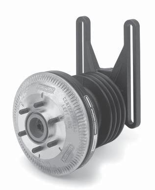
4 LESSON 1: FAN DRIVE SYSTEM 1.1 Operation Learning Objectives Recognize the purpose and advantages of a fan drive. Heavy Duty Fan Drive Fan Radiator When engaged, the fan drive activates the fan to cool the engine by pulling air through the radiator. Depending on the size and rotational speed of the fan, as much as Hp may be needed to run the fan. The fan drive engages only when needed resulting in additional horsepower for drive axles, less noise, and increased fuel economy. Due to these benefits, most new diesel powered vehicles are equipped with a Horton On/Off fan drive. NOTE: An engaged fan drive pulls air through the radiator to cool the engine C-0604
5 Learning Objectives Describe the basic operation of the fan drive control system. Identify the components of a fan drive electrical control system. Describe how air pressure engages/disengages the DriveMaster fan drive. 1.2 Control System Manual Override Switch To Ignition Thermal Switch A/C Refrigerant Pressure Switch Air Filter Air Supply Fan Drive Solenoid Valve The illustration above depicts an independent fan drive control system. The electrically controlled solenoid valve engages and disengages the fan drive by regulating its air pressure on and off. The electrical circuit to the solenoid valve contains three switches. Any of these three switches may activate the solenoid and engage the fan drive: a thermal switch sensing the engine coolant temperature. a Refrigerant Pressure Switch in the vehicle s air conditioning system. an Optional Manual Override Switch located on the vehicle s dashboard. The DriveMaster fan drive is spring-engaged and disengages when air pressure is applied. EXAMPLE. When the engine coolant temperature rises above the thermal switch s set point, the thermal switch activates the solenoid valve, which shuts off air pressure to the fan drive (supplied by the vehicle s air reservoir) and engages the fan. Most newer vehicles are equipped with an Electronic Control Module (ECM), which is a small computer that monitors and controls all engine operations, including the fan drive. If a vehicle uses an ECM, there is no direct connection between the sensors and the solenoid valve for the fan drive. Information from sensors and switches is fed into the ECM which controls the solenoid valve C
6 LESSON 2: CONTROL COMPONENTS Vehicles not using an ECM usually have two sensors to automatically turn the fan on and off. First is the Engine Coolant thermal switch and, second, the Air Conditioning Refrigerant Pressure Switch. 2.1 Engine Coolant Thermal Switch The Engine Coolant thermal switch is mounted in the water jacket on the engine. Learning Objectives Describe the function of a thermal switch in the fan drive control system. State the difference between normally-open and normallyclosed components. Thermal switches are either normally-open or normally-closed depending upon the electrical control system. In a normally-open thermal switch, the electrical contacts are open when the temperature is below the set point and closed when the temperature is above the set point. In a normally-closed thermal switch, the electrical contacts are closed when the temperature is below the set point and open when the temperature is above the set point. NOTE: Thermal switch reset point is usually 7 o F [3.9 o C] below the set point. Truck designers will typically specify a thermal switch with a set point o F [ o C] higher than the fully open temperature of the engine thermostat. 2.2 Refrigerant Pressure Switch The Refrigerant Pressure Switch is installed in the high pressure line of the vehicle s air conditioning system. When the air conditioner is running, heat removed from the air is absorbed by the refrigerant (e.g., freon, R-12 and R-134a). As the refrigerant heats, pressure builds in the air conditioner high pressure line until the refrigerant pressure reaches the switch s set point. The switch then sends a signal to the solenoid valve to engage the fan drive. The fan pulls air through the air conditioner condenser coils, which cools the condenser/refrigerant and reduces refrigerant pressure. Learning Objectives Describe the function of a Refrigerant Pressure Switch in the fan drive control system. NOTE: Air Conditioning Refrigerant Pressure Switches are available as either normally-open or normallyclosed C-0604
7 Learning Objectives Describe the function of a solenoid valve in the fan drive control system. Describe the ideal mounting location for the solenoid valve. 2.3 Solenoid Valve The solenoid valve is the heart of the control system, opening and closing to regulate the air flow to the fan drive. N.O. Inlet Port/ N.C. Exhaust Port NOTE: The solenoid valve is controlled by electricity and is available for 12 and 24 volt electrical systems. The solenoid valve is a 3-way valve having two inlet /exhaust ports and one outlet port. Air pressure from the vehicle s air system is fed into one of the inlet ports and the outlet port is connected to the fan drive. Turning the electric current on and off causes a plunger inside the solenoid valve to move up and down. The plunger connects the valve outlet port to one of the two inlet ports: N.C. Inlet Port/ N.O. Exhaust Port Air Outlet Port To Fan Drive the normally-open port when the electric current is off. the normally-closed port when the electric current is on. The valve has a 3/64" [1.19 mm] orifice to regulate the volume of air and ensure smooth engagement and disengagement of the fan drive. NOTE: Normal (as in normally-open or normally-closed) refers to the state of the solenoid valve, sensor or switch when it is relaxed or de-energized. EXAMPLE. Normal can be defined as the state of the solenoid valve if it was completely disconnected and in your hand - the Solenoid would be de-energized, the normally-open port would be open to the outlet port, and the normally-closed port would be closed to the outlet port. The valve outlet port is always connected to the fan drive. Depending on the vehicle s electrical control circuits, the air supply may be connected to either the normally-open or the normally-closed port. The port not connected to the air supply will exhaust air from the fan drive when it disengages. Various adapters and fittings are available to permit the solenoid valve to be plumbed either normally-open or normally-closed (i.e., the air supply may be connected to either inlet port). These fittings also permit the solenoid valve to be installed with or without an air filter. Mount the solenoid valve in a remote location away from the engine to minimize the valve s exposure to excessive heat, vibration, and contaminants. A solenoid valve mounted off of the engine will prolong the life of the solenoid and ensure proper fan drive operation. Air Supply NO NC OUT Normally-Open Air Supply NO NC OUT Normally-Closed C
8 LESSON 3: ELECTRICAL CONTROL SYSTEMS (ECM) 3.1 Electronic Control Module The electrical wiring that controls the fan drive varies from one vehicle to another, but generally will be one of three types of systems: ECM controlled Normally-Open Normally-Closed Engine manufacturers include Electronic Control Modules (ECMs) in their new designs to control the engine, transmission, and other critical operations to improve engine performance, reliability, and fuel efficiency. An ECM is essentially a digital computer, containing a microprocessor, random-accessmemory (RAM), and read-only-memory (ROM). The ROM contains the computer s program. Design engineers can change a vehicle s control system and engine performance simply by changing the ECM s computer program. Learning Objectives Describe the function of an ECM. State the advantages of an ECM system over an independent hard-wired control system. NOTE: An ECM is essentially a digital computer, used to control the engine, transmission, and other critical operations to improve performance reliability, and efficiency. Electronic Control Modules are simpler and more reliable than independent hard-wired systems. The decision logic is in the computer program and not the wiring, and all sensors and actuators are wired to the ECM instead of to each other. Sensor Common Fan Override Switch Air Temperature Sensor Coolant Temp. Sensor A/C Pressure Switch Engine Speed Sensor Air Supply To indicators and gauges Foot Throttle From other sensors Inputs Electronic Control Module Outputs To electronic injectors and other actuators +12 Volts Fan Relay +12 Volts Solenoid Valve NO NC OUT C-0604
9 Learning Objectives Describe the basic operation of an ECM-Controlled System. Describe how ECM sensors operate differently than switches used in independent hard-wired systems. Trace the path of a sensor signal to fan drive operation in an ECM-controlled system. NOTE: The ECM monitors data from the sensors to send signals to the controls, actuators, and operator s warning lights and gauges. 3.2 Sensors The diagram on the previous page shows that the sensors are not wired to the solenoid valve or any control actuator as in a conventional system. Instead, each sensor goes to an ECM input pin and each actuator is wired to an ECM output pin. The ECM computer monitors the data from the sensors and sends the appropriate signals to the controls and actuators based on programming logic. The ECM also sends status information to the operator s warning lights and gauges. In an ECM controlled system, one sensor may affect several actuators and one actuator may be affected by several sensors, depending on how the ECM is programmed. Sensors used in ECM systems are different than those used in independent systems. Instead of the simple open/close type of sensor, ECM systems use thermistors and sending units to send signals to the ECM (temperature, pressure, speed, or whatever function is being sensed). EXAMPLE. Instead of a thermal switch opening or closing at a preset temperature, ECM s use a temperature sensor to provide voltage which the logic program converts into an actual temperature measurement. Instead of simply knowing if the coolant temperature is above or below the set point (i.e., hotter that 190 o F [88 o C]), the program knows the actual temperature (i.e., o F [91.3 o C]). NOTE: The ECM program considers several factors before determining fan drive engagement. The fan drive solenoid is not wired to the sensors as it is in a conventional system but instead wired to a relay controlled by the ECM. The ECM computer program looks at the data from several sensors and decides when to engage and disengage the fan drive. The program considers engine coolant temperature, air-conditioner s refrigerant pressure, intake-manifold air temperature, engine speed, and the engine brake status, and possibly other factors depending on engine configuration New troubleshooting techniques may be necessary when working on a truck with an ECM control system. A vehicle s wiring diagram no longer indicates which sensor affects which actuator. The diagram only shows which ECM pin each sensor and actuator is connected. To determine the relationships between the sensors and actuators, refer to the vehicle or engine service manual for descriptions of exact conditions under which each actuator is engaged (i.e. Fault Codes) C
10 LESSON 4: ELECTRICAL CONTROL SYSTEMS (NON-ECM) 4.1 Types of Electrical Control Systems The electrical wiring that controls the fan drive varies from one vehicle to another, but generally will be one of three types of systems: Normally-Open Normally-Closed ECM controlled Learning Objectives Describe the basic operation of normally-open and normallyclosed control systems. Describe how solenoid valves should be plumbed in a normally-open or normallyclosed system. Most newer engine designs are ECM controlled. Manufacturers that tend to have normally-closed electrical controls include: Blue Bird GMC Mack Ford International White GMC Manufacturers that tend to have normally-open electrical controls include: Freightliner Mack Western Star Kenworth Volvo Peterbilt The fan drive electrical control system may be normally-open or normally-closed, and the solenoid valve may be plumbed to work in either system. Horton DriveMaster fan drives are plumbed as follows: For a normally-open electrical system, connect the air supply to the normally-open port of the solenoid valve. For a normally-closed electrical system, connect the air supply to the normally-closed port of the solenoid valve. The commonly-used term normally-open system refers to an electrical system. The commonly-used term normally-open valve refers to the pneumatics of the valve C-0604
11 Learning Objectives State how switches are wired in a normally-open control system. Describe the operation of the solenoid valve if all switches are open. Describe the operation of the solenoid valve if a single switch closes. 4.2 Normally-Open Electrical Controls In a normally-open control system, all switches are below their set points and the electrical circuit to the solenoid valve is open. +12 Volts A/C Pressure Switch (NO) Manual Override Switch (NO) Solenoid Valve Air Supply NO NC OUT Thermal Switch (NO) NOTE: A quick, easy way to check if a solenoid is normally-open or normally-closed is to blow in the top. If the air escapes from the outlet port going to the fan drive, the solenoid is normally-open. If the air is blocked from the outlet port going to the fan drive and escapes through the exhaust port, the solenoid is normally-closed. In such a system, all electrical switches are wired in parallel. Electricity from the 12 volt power supply can take any of the three parallel paths to reach the solenoid valve. All three switches are shown in their normal state (open). When all switches are open, no electricity flows to the solenoid valve and the solenoid remains open. The solenoid valve connects the outlet port to the normally-open port and provides air pressure to the fan drive. The fan drive disengages. When one of the electrical switches closes, electricity flows to energize the solenoid valve. The solenoid valve connects the outlet port to the normally-closed inlet port and blocks air pressure going to the fan drive, engaging the fan drive. EXAMPLE. The engine coolant temperature rises above the thermal switch s set point. The normally-open thermal switch closes causing electricity to flow through the thermal switch energizing the solenoid valve. The solenoid valve plunger moves to connect the outlet port to the normally-closed inlet port. Air pressure exhausts through the valve to allow engagement of the fan drive, turning the fan C
12 4.3 Normally-Closed Electrical Controls The following schematic diagram is of a normally-closed electrical control system. When all switches are below their set points, the electrical circuit to the solenoid valve is closed. +12 Volts A/C Pressure Switch (NC) Manual Override Switch (NC) Solenoid Valve Air Supply NO NC Learning Objectives State how switches are wired in a normally-closed control system. State how to determine if a solenoid valve is normallyopen or normally-closed. Describe the operation of the solenoid valve if a switch opens. OUT Thermal Switch (NC) In such a system, all electrical switches are wired in series. Electricity from the 12 volt power supply must flow through all three switches before it reaches the solenoid valve. All three switches are shown in their normal state (closed). Electricity flows to the solenoid valve and the solenoid is energized. The solenoid valve connects the outlet port to the normally-closed inlet port and provides air pressure to the fan drive. The fan drive disengages. When one of the electrical switches opens, the electrical current is broken and the solenoid valve de-energizes. The solenoid valve connects the outlet port to the normally-open inlet port and blocks air pressure to the fan drive, engaging the fan drive. NOTE: A quick, easy way to check if a solenoid is normally-open or normally-closed is to blow in the top. If the air escapes from the outlet port going to the fan drive, the solenoid is normally-open. If the air is blocked from the outlet port going to the fan drive and escapes through the exhaust port, the solenoid is normally-closed. EXAMPLE. The engine coolant temperature rises above the thermal switch s set point. The normally-closed thermal switch opens, causing a break in the electrical current and de-energizing the solenoid valve. The solenoid valve plunger moves to connect the outlet port to the normally-open inlet port. Air pressure exhausts through the valve and allows engagement of the fan drive, turning the fan C-0604

13 Learning Objectives For each type of control system determine: 1) if switches are wired in parallel or series, 2) if sensors are used, 3) the proper port to plumb the solenoid valve, and 4) the proper method to test the fan drive. 4.4 Comparison - Open/Closed Electrical Controls Normally-Open Electrical System Normally-Closed Electrical System Electrical switches are wired in parallel. Air supply plumbed to solenoid s normally-open port (the end port). Test fan drive by installing a jumper wire across a sensor. Manual Override Switch (if equipped). Electrical switches are wired in series. Air supply plumbed to solenoid s normally-closed port (the side port). Test fan drive by disconnecting a wire from a sensor. Manual Override Switch (if equipped). Learning Objectives (Review Only) 4.5 Summary - Open/Closed Electrical Controls Normally-open Electrical System with normally-open solenoid valve All switches open Solenoid de-energized Drive disengaged Any switch closed Solenoid energized Drive engaged normally-closed Electrical System with normally-closed Solenoid Valve All switches closed Solenoid energized Drive disengaged Any switch open Solenoid de-energized Drive engaged C
14 LAB ACTIVITY - FAN DRIVE CONTROL COMPONENTS Locate a truck with a Horton DriveMaster fan drive, preferably a make and model you would work on. Locate the components listed below and answer the questions by filling in the corresponding blanks and checking the box next to the number when you complete a step. Upon completion, please check this activity with an instructor or supervisor. Learning Objective Locate and identify components of the fan drive system. Interpret the vehicle's electrical diagram for various fan drive system components. 1. Locate the DriveMaster fan drive and list the model. 2. Locate the solenoid valve. For your safety, be sure the engine is off. 3. Locate the fan drive air filter (if equipped). 4. Locate the coolant temperature switch or sensor. 5. Locate the air-conditioning refrigerant pressure switch (if equipped). 6. Locate the fan drive manual override switch (if equipped). 7. How many belts are on the fan drive sheave? 8. What engine components do the belts go around? 9. How many bolts mount the fan drive to the engine? 10. Locate the air hose that supplies air to the solenoid. Where does the hose attach to the air supply? 11. Does the truck have an ECM? 12. In the truck s service manual, locate the electrical diagram for the fan drive control solenoid and the ECM. 13. Draw the schematic symbol used in your truck s electrical diagram for each of the following components: Solenoid Valve Engine-Coolant Thermal Switch/Sensor Air-Conditioning Refrigerant Pressure Switch/Sensor Manual Override Switch C-0604
15 REVIEW QUESTIONS - FAN DRIVE CONTROL SYSTEM 1. Advantages of using a Horton fan drive include increased horsepower, consistent coolant temperature, and increased fuel economy. True / False 2. In the operation of most ECM-controlled fan drive systems without a relay, the ECM sends a direct signal to the Solenoid valve to engage or disengage the friction disc. True / False 3. Identify this component by circling its name. COMPONENTS A. Solenoid Valve B. Engine Coolant Thermal Switch C. Refrigerant Pressure Switch 4. Identify this component by circling its name. COMPONENTS A. Solenoid Valve B. Engine Coolant Thermal Switch C. Refrigerant Pressure Switch 5. Identify this component by circling its name. COMPONENTS A. Solenoid Valve B. Engine Coolant Thermal Switch C. Refrigerant Pressure Switch 6. The fan drive is engaged when air pressure is applied through the solenoid valve. True / False 7. The engine coolant thermal switch sends a signal to engage the fan drive when the engine coolant reaches the switch s high set point. True / False 8. In a normally-closed electrical control system, electrical contacts are closed when engine temperature and air conditioning pressure are below high set points. True / False 9. When air conditioning pressure reaches the low set point, a signal is sent to the solenoid valve or ECM by the a) thermal switch, b) Solenoid Switch, c) Refrigerant Pressure Switch. 10. The solenoid valve functions to regulate air to each of the electrical control components. True / False 11. It is best to locate the solenoid valve close to the fan drive, and on the engine block if possible. True / False C
16 12. An Electronic Control Module is: a) a computer, b) a sensor, c) a sending unit 13. ECM control systems improve engine performance, reliability and fuel efficiency more than non-ecm control systems. True / False 14. ECMs monitor data from sensors and send the appropriate signals to controls and actuators based on: a) operator options, b) programming logic, c) vehicle service periods. 15. In most ECM-controlled systems, sensors and actuators are wired directly to the ECM, not the solenoid valve. True / False 16. Draw the path of a sensor signal to fan drive operation in an ECM-controlled system. Sensor Common Fan Override Switch Air Temperature Sensor Coolant Temp. Sensor A/C Pressure Switch Engine Speed Sensor Air Supply To indicators and gauges Foot Throttle From other sensors Inputs Electronic Control Module Outputs To electronic injectors and other actuators 17. To find fault code explanations when troubleshooting ECM-controlled systems, look: a) under the hood, b) inside the door panel, c) in the service manual. 18. The three types of fan drive control systems are ECM-controlled, normally-open and normally-closed. True / False 19. If a vehicle has a normally-open control system, the air supply for the DriveMaster should be connected to the: a) normally-open, or B) normally-closed, port of the 3-way solenoid valve. 20. In a normally-open control system, switches are wired in: a) series, b) parallel. 21. On the diagram, connect the electrical components for a normally-open control system and indicated if the air supply is connected to the solenoid valve s normally-open or normally-closed inlet port. +12 Volts Fan Relay +12 Volts Solenoid Valve NO NC OUT Fan Relay: Not in all Systems +12 Volts A/C Pressure Switch (NO) Manual Override Switch (NO) Solenoid Valve NO NC Thermal Switch (NO) OUT C-0604
17 22. When all switches are open in normally-open control system, the solenoid is: a) energized, b) de-energized, and the fan drive is: a) engaged, b) disengaged. 23. If a switches closes in a normally-open control system, the solenoid is: a) energized, b) de-energized, and the fan drive is: a) engaged, b) disengaged. 24. In a normally-closed control system, switches are wired in parallel. True / False 25. On the diagram below, connect the electrical components for a normally-closed control system and indicate if the air supply is connected to the solenoid valve s normally-open or normally-closed inlet port. +12 Volts A/C Pressure Switch (NC) Manual Override Switch (NC) Thermal Switch (NC) Solenoid Valve NO NC OUT 26. Air will escape through the outlet port going to the fan drive of a normally-open solenoid valve when air is applied to the normally-open port. True / False 27. If a switch opens in a normally-closed control system, the solenoid is: a) energized, b) de-energized, and the fan drive is a) engaged, b) disengaged. 28. The fan drive can be tested in a normally-open control system by disconnecting a wire from a sensor. True / False C
18 Review Answers - Fan Drive Control System 1. Advantages of using a Horton fan drive include increased horsepower, consistent coolant temperature, and increased fuel economy. True / False 2. In the operation of most ECM-controlled fan drive systems without a relay, the ECM sends a direct signal to the Solenoid valve to engage or disengage the friction disc. True / False 3. Identify this component by circling its name. COMPONENTS A. Solenoid Valve B. Engine Coolant Thermal Switch C. Refrigerant Pressure Switch 4. Identify this component by circling its name. COMPONENTS A. Solenoid Valve B. Engine Coolant Thermal Switch C. Refrigerant Pressure Switch 5. Identify this component by circling its name. COMPONENTS A. Solenoid Valve B. Engine Coolant Thermal Switch C. Refrigerant Pressure Switch 6. The fan drive is engaged when air pressure is applied through the solenoid valve. True / False 7. The engine coolant thermal switch sends a signal to engage the fan drive when the engine coolant reaches the switch s high set point. True / False 8. In a normally-closed electrical control system, electrical contacts are closed when engine temperature and air conditioning pressure are below high set points. True / False 9. When air conditioning pressure reaches the low set point, a signal is sent to the solenoid valve or ECM by the a) thermal switch, b) Solenoid Switch, c) Refrigerant Pressure Switch. 10. The solenoid valve functions to regulate air to each of the electrical control components. True / False 11. It is best to locate the solenoid valve close to the fan drive, and on the engine block if possible. True / False C-0604
19 12. An Electronic Control Module is: a) a computer, b) a sensor, c) a sending unit 13. ECM control systems improve engine performance, reliability and fuel efficiency more than non-ecm control systems. True / False 14. ECMs monitor data from sensors and send the appropriate signals to controls and actuators based on: a) operator options, b) programming logic, c) vehicle service periods. 15. In most ECM-controlled systems, sensors and actuators are wired directly to the ECM, not the solenoid valve. True / False 16. Draw the path of a sensor signal to fan drive operation in an ECM-controlled system. Sensor Common Fan Override Switch Air Temperature Sensor Coolant Temp. Sensor A/C Pressure Switch Engine Speed Sensor Air Supply To indicators and gauges Foot Throttle From other sensors Inputs Electronic Control Module Outputs To electronic injectors and other actuators +12 Volts Fan Relay +12 Volts Solenoid Valve NO NC OUT Fan Relay: Not in all Systems 17. To find fault code explanations when troubleshooting ECM-controlled systems, look: a) under the hood, b) inside the door panel, c) in the service manual. 18. The three types of fan drive control systems are ECM-controlled, normally-open and normally-closed. True / False 19. If a vehicle has a normally-open control system, the air supply for the DriveMaster should be connected to the: a) normally-open, or B) normally-closed, port of the 3-way solenoid valve. 20. In a normally-open control system, switches are wired in: a) series, b) parallel. 21. On the diagram, connect the electrical components for a normally-open control system and indicated if the air supply is connected to the solenoid valve s normally-open or normally-closed inlet port. +12 Volts A/C Pressure Switch (NO) Manual Override Switch (NO) Solenoid Valve NO NC Air Supply Thermal Switch (NO) OUT C
20 22. When all switches are open in normally-open control system, the solenoid is: a) energized, b) de-energized, and the fan drive is: a) engaged, b) disengaged. 23. If a switches closes in a normally-open control system, the solenoid is: a) energized, b) de-energized, and the fan drive is: a) engaged, b) disengaged. 24. In a normally-closed control system, switches are wired in parallel. True / False 25. On the diagram below, connect the electrical components for a normally-closed control system and indicate if the air supply is connected to the solenoid valve s normally-open or normally-closed inlet port. +12 Volts Manual Override Switch (NC) Air Supply A/C Pressure Switch (NC) Solenoid Valve NO NC OUT Thermal Switch (NC) 26. Air will escape through the outlet port going to the fan drive of a normally-open solenoid valve when air is applied to the normally-open port. True / False 27. If a switch opens in a normally-closed control system, the solenoid is: a) energized, b) de-energized, and the fan drive is a) engaged, b) disengaged. 28. The fan drive can be tested in a normally-open control system by disconnecting a wire from a sensor. True / False C-0604
21 PRIOR TO SERVICING You must follow your company safety practices, which should adhere to or be better than Federal or State approved shop safety practices and procedures. Be sure that you read and understand all the procedures and instructions before beginning work on this unit. NOTE Parts replacement and/or repair of your Horton DRIVE MASTER fan drive should be performed only by the Horton Factory or an authorized Horton Distributor or Dealer to keep your warranty coverage intact during the warranty period. Before rebuilding your DRIVEMASTER fan drive, note the fan drive Serial No., Service Part No., Date of Installation, and Vehicle Mileage. Serial No. Part Number and Serial Number Service Part No. Installation Date Vehicle Mileage C
22 LESSON 5: DRIVEMASTER PARTS AND REPAIR KITS 5.1 Parts Identification Learning Objectives Recognize externally visible parts Identify commonly replaced parts ITEM DESCRIPTION QTY 1 Fan Mounting Disc/Studs 1 2 Button Head Screws 8 3 Friction Liner 1 4 Cage Nut (Used for repairs only) - 5 Spring Housing / Piston 1 6 Air Chamber Seal 1 7 Air Chamber Cap Retaining Ring 1 8 O-Ring Seal 1 9 Air Chamber Cap 1 10 Face Seal 1 11 Bearing Nut 1 12 Air Cartridge Retaining Ring 1 13 Air Cartridge Assembly 1 14 Ball Bearings Bearing Spacers Sheave Journal Bracket 1 1 Not used on all fan drives 2 Denotes item is not include in Repair Kit C-0604
23 Learning Objectives Describe when a Seal Kit would be used. 5.2 Repair Kits Horton offers several different ways to repair or rebuild your DriveMaster fan drive. For specific part numbers, visit the online catalog at or call Horton Customer Service at DriveMaster Seal Kit Install a Seal Kit if an air leak has developed inside of the DriveMaster fan drive. The Seal Kit consists of the parts listed and described below: 2 4 Button Head Screws (#2): Used to attach the friction liner and the spring housing / piston assembly to the sheave. Cage Nut (#4): Used to keep the spring housing / piston assembly together when removing from the sheave. It maintains pressure on internal springs after the Button Head Screws are removed. Air Chamber Seal (#6): Forms an air seal between the air chamber and the spring housing / piston assembly. It is positioned around the bottom half of the spring housing / piston assembly. Retaining Rings (#7, #12): There are two retaining rings in the seal kit. The smaller retaining ring is used to hold the air cartridge inside the journal bracket shaft. When installing this retaining ring, the beveled side must be facing the air cartridge. The larger retaining ring is used to hold the air chamber cap in place. O-Ring (#8): Forms an air seal between the air chamber and the air chamber cap. Face Seal (#10): Screws into the center of the air chamber cap, forming an air seal with the carbon tip of the air cartridge. Air Cartridge (#13): Fits inside the journal bracket shaft. Air pressure comes up through the center of the shaft, into and through the air cartridge, and into the air chamber. The air cartridge has a spring loaded carbon tip that presses against the face seal, forming an air tight seal while the fan drive is spinning. T55 Torx Plus Bit (not pictured): Used to help remove the fan mounting disc from the jack bolt. O-Ring Lubricant (not pictured): Apply lubricant to the new air chamber cap O-ring and the air chamber seal before installation C
24 2. DriveMaster Super Kit Learning Objectives Describe when a Super Kit Install a Super Kit if the bearings are running rough or if the DriveMaster fan drive needs to be completely rebuilt due to excessive wear. The Super Kit consists of the parts listed and described below: would be used Fan Mounting Disc (#1): The fan mounting disc is the part that the fan is bolted on to. It is also the part that contacts the friction liner when the fan drive is engaged. The fan mounting disc is screwed onto the jack bolt. Different DriveMasters have different stud lengths. Check this when making repairs. Button Head Screws (#2) Friction Liner (#3): Attached to the sheave on top of the spring housing / piston assembly. Cage Nut (#4) Spring Housing / Piston Assembly (#5): The internal mechanism that engages and disengages the DriveMaster fan drive when air pressure is either removed or applied. Air Chamber Seal (#6) Retaining Rings (#7, #12) O-Ring (#8) Face Seal (#10) Bearing Nut (#11): Used to hold the sheave onto the journal bracket shaft. Air Cartridge (#13) Sheave Bearings (#14): Use a bearing press to remove old bearings and install new bearings into the center of the sheave. The bearings are prelubricated and sealed. They are also contain markings that need to be aligned for proper installation. (If there are spacers in between the old bearings that were removed, reuse those spacers by positioning them between the new bearings before installation. DO NOT remove the seals and attempt to lubricate the old or new bearings.) Some DriveMasters use one double row bearing instead of the two single row bearings. Check to make sure you have the right kit. T55 Torx Plus Bit (not pictured) O-Ring Lubricant (not pictured) C-0604
25 Learning Objectives Describe when a DriveMaster PolarExtreme Super Kit would be used. 2. DriveMaster PolarExtreme Super Kit Install a DriveMaster PolarExtreme Super Kit if the bearings are running rough or if the DriveMaster fan drive needs to be completely rebuilt due to excessive wear. If you need more power, the PolarExtreme kit also contains an ultra high-torque clutch package that delivers 2400 inch-pounds of torque.the Kit consists of the parts listed and described below: Single Bearing Dual Bearing Sheave Bearings (#2): Use a bearing press to remove old bearings and install new bearings into the center of the sheave. The bearings are prelubricated and sealed. They are also contain markings that need to be aligned for proper installation. (If there are spacers in between the old bearings that were removed, reuse those spacers by positioning them between the new bearings before installation. DO NOT remove the seals and attempt to lubricate the old or new bearings.) Bearing Nut (#4): Used to hold the sheave onto the journal bracket shaft. O-Ring Seal (#6) Fan Mounting Disc/Studs (#9): The fan mounting disc is the part that the fan is bolted on to. It is also the part that contacts the friction liner when the fan drive is engaged. The fan mounting disc is screwed onto the jack bolt. Button Head Screws (#17) Air Chamber Seal (#18) Face Seal (#20) Retaining Ring (#22) Air Cartridge Assembly (#23) Retaining Ring (#24) Friction Liner (#28): Attached to the sheave on top of the spring housing / piston assembly. Spring Housing / Piston Assembly (#50): The internal mechanism that engages and disengages the DriveMaster fan drive when air pressure is either removed or applied. Cage Nut (#55) C
26 3. DriveMaster Friction Disc Kit Install a friction disc kit if the fan mounting disc is damaged from blistering, excessive wear, or failure. The friction disc kit consists of the parts listed and described below: Learning Objectives Describe when a Friction Disc Kit would be used. Fan Mounting Disc (#1) Button Head Screws (#2) Friction Liner (#3) Cage Nut (#4) T55 Torx Plus Bit (not pictured) 4. DriveMaster Friction Liner Kit Install a Friction Liner kit if the friction liner is worn. Check the fan mounting disc to make sure there is no excessive wear. If damage is evident use the DriveMaster friction disc kit. The Liner kit consists of the parts listed and described below: Learning Objectives Describe when a Friction Liner Kit would be used. 2 Button Head Screws (#2) Friction Liner (#3) Cage Nut (#4) T55 Torx Plus Bit (not pictured) C-0604
27 LESSON 6: REMOVING THE FAN DRIVE Learning Objectives Describe the safety precautions and order of steps in removing the fan drive from the vehicle. NOTE: The procedure for removing the fan drive varies from one vehicle to another. Refer to the vehicle s service manual for a detailed description of this process. NOTE: Protect the radiator from possible damage from the fan during fan removal and fan drive installation. 1. Turn the vehicle ignition off. 2. Apply the vehicle's parking brake. 3. Block the vehicle's wheels. 4. Bleed the air from the vehicle s reservoir. 5. Disconnect the air supply line from the fan drive. 6. Loosen the bolts that hold the fan in place. 7. Remove the fan from the fan drive. 8. Remove any drive belts from the fan drive. 9. Remove the fan drive mounting bolts. 10. Carefully maneuver the fan drive out of the engine compartment. NOTE: Because of the weight of the fan drive (ranging from Lbs. [ Kg]), you may want to use a hoist for support during removal. Fan Drive Grade 8 Mounting Bolts Grade 8 Nuts Steps C

28 LESSON 7: DISASSEMBLING THE FAN DRIVE 7.1 Tools Required 2 Socket Wrench T55 Torx Plus Bit (994352) T27 Torx Bit Torque Wrench Pry Bar Ring Pliers Screwdrivers 7.2 Disassembly Fan Mounting Disc Removal and Inspection 1. Place the fan drive in a vise and clamp the journal bracket tight. 2. Loosen the jack bolt (left hand thread) by turning it counter-clockwise using a T55 Torx Plus Bit (Part# ). Learning Objectives Describe the steps of safely removing and inspecting the fan mounting disc. Recognize signs of wear or damage to the fan mounting disc. NOTE: Applying PSI [ bar] air pressure to the fan drive air inlet will aid in removal of the FMFD. NOTE: Use caution when handling the prybar on the fan mounting disc. Permanent damage may occur if not properly supported. Use a flat blade tool or a prybar that has a handle. Pry Bar Pry Bar Placement Torx Wrench Air Line Steps C-0604
 Step 3 4.")

29 3. Unscrew the fan mounting disc from the jack bolt. Fan Mounting Disc Jack Bolt (left hand thread) Step 3 4. Inspect the fan mounting disc for wear or damage. Step 4 Fan Mounting Disc Good Condition Look for signs of damage or blistering Fan Mounting Disc Bad Condition C
30 Spring Housing / Piston Assembly Removal 5. Using the Torx wrench to hold the jack bolt, hand-tighten the cage nut (from the Repair Kit) onto the jack bolt (left hand thread) over the Spring Housing. The cage nut will keep the Spring Housing and Piston together as an assembly. It will also maintain pressure on the internal Springs after the Button Head Screws are removed. 6. Remove the 8 Button Head Screws using a T27 Torx Bit. 7. Remove the Friction Liner. 8. Remove the spring housing / piston assembly. 9. Remove the air chamber seal. 10. Examine the inside of the Air Chamber for signs of moisture and/or contaminants. Button Head Screws Friction Liner Cage Nut Spring Housing / Piston Assembly Steps 5-7 Spring Housing / Piston Assembly Air Chamber Learning Objectives Describe the steps of safely removing and inspecting the spring housing / piston assembly. Remove air pressure from the unit before proceeding to Step 6. Failure to release air pressure may result in serious personal injury. Do not disassemble the Spring Housing. Personal injury could occur. NOTE: If you are installing either a friction liner (Part# ) or Fan Disc Kit (Part# ), proceed to page 33, step 20. The Air Chamber should be clean and moisture-free (with the exception of the seal lubricant). If not, a problem may exist in the vehicle air system and must be corrected before the fan drive is reinstalled. Steps C-0604
31 Learning Objectives Describe the steps of removing and inspecting the air chamber seals. Wear eye safety protection when removing retaining ring to avoid serious injury. If dirt or oil exists in the air system, the air system must be cleaned and dried before the fan drive is reinstalled. Air Chamber Seals 11. Remove the air chamber cap retaining ring. 12. Gently and evenly pry the air chamber cap out of the sheave using two small screwdrivers placed 180 apart. 13. Remove the O-ring Seal from the air chamber cap. 14. Remove the face seal. 15. Inspect the face seal for signs of wear. Wear indicates that dirt may exist in the air system. Air Chamber Seal Retaining Ring Air Chamber Cap Steps O-Ring Seal Face Seal NOTE: If you are only installing a Seal Kit (Part #994346), proceed to page 30, step 20. Learning Objectives Describe the steps of removing the sheave from the journal bracket. Sheave and Sheave Bearings 16. Remove the Bearing Nut from the journal bracket using a 2 Socket Wrench. Bearing Nut Journal Bracket Step Remove the sheave from the journal bracket. Sheave Journal Bracket Step Fully support the sheave and press out the bearings. 19. Fully clean and remove any dirt, debris or corrosion that may be present. SUPPORT Bearings SUPPORT PRESS TO REMOVE C
32 Air Cartridge Removal 20. Remove the retaining ring. Retaining Ring Learning Objectives Describe the steps of removing the air cartridge. Step 20 Wear eye safety protection when removing retaining ring to avoid serious injury. 21. Remove the Air Cartridge Assembly. Air Cartridge Assembly 22. Clean the journal bracket bore if necessary. Step 21 LESSON 8: REBUILDING THE FAN DRIVE Float Seal Tip NOTE If you are installing a Seal Kit (Part #994346), proceed to page 31, Step Torque Specifications ITEM DESCRIPTION TIGHTENING TORQUE Bearing Nut Jack Bolt (left hand thread) Button Head Screws Face Seal 130 Ft. Lbs. [176 N m] 100 Ft. Lbs. [136 N m] 80 In. Lbs. [9 N m] In. Lbs. [ N m] 8.2 Rebuilding Sheave Bearing Replacement 2. Fully supporting the sheave, press the new sheave bearings (or single bearing) into place, noting the position of the lip inside the sheave. Press outer bearing race to avoid damaging bearings. See Figures 1A, 1B, 1C. Align the chevron markings on the bearings to form an arrow. The arrow may point in either direction. Step 1A Learning Objectives Describe the steps of removing and replacing the sheave bearings C-0604
33 NOTE: Some models of the DRIVEMASTER fan drive contain bearing spacers. Both bearing spacers must be positioned BETWEEN the sheave bearings when the sheave bearings are replaced. LIP INSIDE OF SHEAVE Bearings (or single bearing) Step 1B Bearings Spacers NOTE: All bearings are prelubricated and sealed. DO NOT remove the seals to lubricate the bearings. NOTE: Some DRIVEMASTER models utilize a single (one piece) sheave Bearing. Step 1C PRESS SUPPORT SUPPORT 2. Slide the sheave onto the journal bracket. 3. Replace and tighten the Bearing Nut to 130 Ft. Lbs. [170 N m] torque. Bearing Nut (Hex faces up) Sheave Journal Bracket 4. Be sure that the Bearing Nut hex is facing up (see detail below). Step 2-3 Hex faces up Relief points down toward journal bracket and bearings Step 4 Learning Objectives Describe the steps of removing and replacing the air cartridge. Air Cartridge 5. Apply O-ring lubricant to the outside O- rings of the new air cartridge assembly. O-Rings The retaining ring must be fully seated in the retaining ring groove to keep the air cartridge assembly from moving. Also, the retaining ring is beveled. The curved side must be installed facing the Cartridge. 6. Install the new air cartridge assembly into the journal bracket. 7. Reinstall the retaining ring. Step 5 Retaining Ring The curve faces the Cartridge C
34 Spring Housing / Piston Assembly Reassembly 8. Using a clean/dry cloth, clean the float seal tip (see air cartridge illustration, Step 4) of the air cartridge assembly. Learning Objectives Describe the steps of safely reassembling the spring housing / piston assembly. 9. Also clean the face seal of the air chamber cap. State lubrication requirements and cautions when reassembling the spring housing / piston assembly. 10. Assemble the air chamber cap and face seal. 11. Lubricate the O-ring Seal with the fresh lubricant supplied in the kit. 12. Install the O-ring Seal on the air chamber cap. 13. Carefully set the air chamber cap into the sheave. 14. Install the retaining ring. Air Chamber Cap Retaining Ring Steps Sheave Use extreme care when reassembling the Air Chamber components to avoid damage to the O-ring and air chamber seal. NOTE: The new face seal is assembled with an O-ring. If the old face seal does not have an O-ring, remove it from the new face seal and apply thread sealant (Loctite 511 or similar) to the face seal threads. 15. Install the air chamber seal into the sheave. 16. Be sure the Seal is evenly seated against the side and bottom of the groove surfaces. 17. Lubricate contact surfaces with the fresh lubricant supplied in the kit. 18. Carefully set the new spring housing / piston assembly from the Repair Kit into position. 19. Gently rotate to align the mounting holes in the assembly with the sheave. Seat Seal evenly against side and bottom groove surfaces. Do not apply grease beyond these areas. Step Spring Housing / Piston Assembly Piston Sheave (cross-section) Air Chamber Seal Detail V of Seal faces down into sheave Do not apply grease beyond Seal contact surface as it will cause improper fan drive function. NOTE: The entire tube of O-ring lubricant should be used when lubricating the new seals and contact surfaces of the sheave and spring housing / piston assembly. Air Chamber Seal Steps C-0604
![To avoid personal injury, make sure the Button Head Screws are properly tightened to the specified torque before applying air pressure - 80 In. Lbs. [9 N m]. 20.](/docs-images/90/101612193/images/35-0.jpg "Set the new friction liner (from kit) into place. Handle the friction liner by the edges to avoid contamination. 21. Alternately and evenly tighten the 8 Button Head Screws to 80 In. Lbs.")
35 To avoid personal injury, make sure the Button Head Screws are properly tightened to the specified torque before applying air pressure - 80 In. Lbs. [9 N m]. 20. Set the new friction liner (from kit) into place. Handle the friction liner by the edges to avoid contamination. 21. Alternately and evenly tighten the 8 Button Head Screws to 80 In. Lbs. [9 N m] torque. Button Head Screws Friction Liner Cage Nut Spring Housing/ Piston Assembly Learning Objectives Describe the steps of safely installing the fan mounting disc. Fan Mounting Disc Reassembly Steps NOTE: Air must be applied to the air chamber to allow for easy removal of the cage nut and to ensure proper torque is applied to the jack bolt. Do not disassemble the Spring Housing. Personal injury could occur. 22. Apply a minimum of 80 lbs. PSI of clean air to the air inlet. 23. Remove the cage nut from the spring housing / piston assembly. 24. Install the new fan mounting disc (from kit) if applicable. Fan Mounting Disc Jack Bolt (left hand thread) If a problem exists, it must be corrected prior to mounting the fan drive onto the vehicle. If the problem is not corrected, the fan drive will fail prematurely. 25. Tighten the jack bolt (left hand thread) to 100 Ft. Lbs. [136 N m] torque. 26. Actuate the DRIVEMASTER and check for proper engagement and disengagement of the fan mounting disc. 27. Check for air leaks at the bleed hole. 28. Check for air leaks around the spring housing / piston assembly. Step 24 Step C
HT650 TM FAN DRIVE SERVICE INSTRUCTIONS
 HT650 TM FAN DRIVE SERVICE INSTRUCTIONS When unpacking your product, remove all components and inspect them to ensure that no damage occurred during shipping. If any components are missing or damaged,
HEATING AND AIR CONDITIONING
 WJ HEATING AND AIR CONDITIONING 24-1 HEATING AND AIR CONDITIONING TABLE OF CONTENTS page SERVICE PROCEDURES REFRIGERANT OIL LEVEL...1 REFRIGERANT RECOVERY....1 REFRIGERANT SYSTEM CHARGE...1 REFRIGERANT
HEATING AND AIR CONDITIONING
 XJ HEATING AND AIR CONDITIONING 24-1 HEATING AND AIR CONDITIONING TABLE OF CONTENTS page DESCRIPTION AND OPERATION SERVICE WARNINGS AND PRECAUTIONS...1 COMPRESSOR - 2.5L VM DIESEL....3 COMPRESSOR CLUTCH
Series 47 and 247 Mechanical Water Feeders. Series 47-2 and Combination Mechanical Water Feeder/Low Water Cut-Off ! WARNING
 Series 47 and 247 Mechanical Water Feeders McDonnell & Miller Installation & Maintenance Instructions MM-316(C) Series 47-2 and 247-2 Combination Mechanical Water Feeder/Low Water Cut-Off Series 47 Water
Audi-Larm Audible Alarm
 Audi-Larm Audible Alarm MAINTENANCE AND REPAIR TAL 1706 (L) Rev. 7 MSA 2017 Prnt. Spec. 10000005389(I) Mat. 10093084 Doc. 10093084 REPLACEMENT KITS AND PARTS LIST TAL 1706 (L) Rev. 7-10093084 2 Exploded
Water Distiller Service Manual
 Water Distiller Service Manual Water Distiller Service Manual L70478WT 2008 Regal Ware, Inc. Table of Contents RECOMMENDED TOOLS... 2 GENERAL INSPECTION...3 BOILING CHAMBER TROUBLESHOOTING & REPAIRS Description...
JOHN DEERE GATOR HPX/XUV 2 PASSENGER HEATER INSTALLATION INSTRUCTIONS (p/n: 9PH20S30)
") P. 1 of 12 JOHN DEERE GATOR HPX/XUV 2 PASSENGER HEATER INSTALLATION INSTRUCTIONS (p/n: 9PH20S30) Item: Qty: Description: 1 2 1 x 1 x 5/8 Tee Fitting 2 2 Plastic Snap-in Hose Grommet 3 4 1-1/2" Hose Clamps
P. 1 of 12 JOHN DEERE GATOR HPX/XUV 2 PASSENGER HEATER INSTALLATION INSTRUCTIONS (p/n: 9PH20S30) Item: Qty: Description: 1 2 1 x 1 x 5/8 Tee Fitting 2 2 Plastic Snap-in Hose Grommet 3 4 1-1/2" Hose Clamps
ModulAir Air Dryer with External Purge Tank - Changeover from Bendix AD-IS for Peterbilt Installation. Air Dryer Mounting Bracket (Item 1)
") Instruction Guide L31259 11/10 ModulAir Air Dryer with External Purge Tank - Changeover from Bendix AD-IS for Peterbilt Installation Air Dryer Mounting Bracket (Item 1) Tank Mounting Bracket (Item 19)
Instruction Guide L31259 11/10 ModulAir Air Dryer with External Purge Tank - Changeover from Bendix AD-IS for Peterbilt Installation Air Dryer Mounting Bracket (Item 1) Tank Mounting Bracket (Item 19)
INSTALLATION GUIDE. Yellow Jacket Misting System. For help, call BIG-FANS or visit
 INSTALLATION GUIDE Yellow Jacket Misting System For help, call 1-877-BIG-FANS or visit www.bigassfans.com READ AND SAVE THESE INSTRUCTIONS WARNING AND CAUTION SYMBOL Indicates a hazard with a medium level
SD Bendix AD-1 and AD-2 Air Dryers
 SD-08-2403 Bendix AD-1 and AD-2 Air Dryers AD-1 AIR DRYER AD-2 AIR DRYER FIGURE 1 The air dryer collects and removes moisture and contaminants before the air reaches the first reservoir. It is distinctly
System Saver TWIN Air Dryer. Maintenance Manual 35 Revised 11-02
 System Saver TWIN Air Dryer Maintenance Manual 35 Revised 11-02 Service Notes This publication provides maintenance and service procedures for Meritor WABCO s System Saver TWIN air dryers. The information
SECTION air supply system + WARNING: + NOTE: GENERAL DESCRIPTION COMPRESSED AIR RESERVOIRS / 1.
 08-000.02/ 1 2011JA14 SECTION 08-000.02 GENERAL DESCRIPTION See Figure 1 for a schematic diagram of the. See the Nova LFS parts manual for a detailed schematic of the. The function of the vehicle s is
INSTALLATION AND SERVICE MANUAL FOR THE SERIES 2000 & SERIES 3000 FAN SERIES GEN 2
 INSTALLATION AND SERVICE MANUAL FOR THE SERIES 2000 & SERIES 3000 FAN SERIES GEN 2 (PNEUMATIC CONTROL AND HYDRAULIC CONTROL) PUBLICATION No. 01900 Revision 2 Printed in Canada 1.1 INTRODUCTION Thank you
DRY AIR SYSTEMS, INC Metro Boulevard Maryland Heights, Missouri (314) fax (314)
 fax (314)") DRY AIR SYSTEMS, INC. 2655 Metro Boulevard Maryland Heights, Missouri 63043 (314) 344-1114 fax (314) 344-0677 HD SERIES DRIERS TABLE OF CONTENTS WHY AN AIR DRYER 3 WHAT IS A DESICCANT AIR DRYER 3 Desiccant
DRY AIR SYSTEMS, INC. 2655 Metro Boulevard Maryland Heights, Missouri 63043 (314) 344-1114 fax (314) 344-0677 HD SERIES DRIERS TABLE OF CONTENTS WHY AN AIR DRYER 3 WHAT IS A DESICCANT AIR DRYER 3 Desiccant
INSTALLATION AND SERVICE MANUAL FOR THE SERIES 2000 & SERIES 3000 FAN SERIES GEN 1
 INSTALLATION AND SERVICE MANUAL FOR THE SERIES 2000 & SERIES 3000 FAN SERIES GEN 1 (PNEUMATIC CONTROL AND HYDRAULIC CONTROL) PUBLICATION No. 01524 Revision 15 Printed in Canada 1.1 INTRODUCTION Thank
Installation Instructions Part No , Part No Part No
 Torsion-Flex Motor mount for PSC motors and Rigid-Mount for ECM motors Replacement Kit Cancels: New Installation Instructions Part No. 327752-401, Part No. 327753-401 Part No. 327754-401 IIK-310A-45-11
SECTION 1D ENGINE COOLING
 SECTION 1D ENGINE COOLING CAUTION: Disconnect the negative battery cable before removing or installing any electrical unit or when a tool or equipment could easily come in contact with exposed electrical
HEATING AND VENTILATION
 SECTION 14-102.04 14-102.04/ 1 2007OC19 DESCRIPTION The heating, ventilation and air conditioning (HVAC) system is designed to optimize passenger comfort. The system regulates interior vehicle atmosphere,
INSTALLATION AND SERVICE MANUAL FOR THE SERIES 1000-P FAN SERIES (PNEUMATIC CONTROL) SERIES 1000-H FAN SERIES (HYDRAULIC CONTROL) GEN 2
 SERIES 1000-H FAN SERIES (HYDRAULIC CONTROL) GEN 2") INSTALLATION AND SERVICE MANUAL FOR THE SERIES 1000-P FAN SERIES (PNEUMATIC CONTROL) SERIES 1000-H FAN SERIES (HYDRAULIC CONTROL) GEN 2 Publication No. 01906 Revision 0 Printed in Canada 1.1 INTRODUCTION
INSTALLATION AND SERVICE MANUAL FOR THE SERIES 1000-P FAN SERIES (PNEUMATIC CONTROL) SERIES 1000-H FAN SERIES (HYDRAULIC CONTROL) GEN 2 Publication No. 01906 Revision 0 Printed in Canada 1.1 INTRODUCTION
BC BRONCOS AIR CONDITIONING UNIT
 BC BRONCOS AIR CONDITIONING UNIT CAUTION If you are not familiar with the principals of air conditioning, have an authorized air conditioning technician evacuate and charge the system. Serious damage to
DF400/DF600. Construction Heaters. Installation and Maintenance Manual
 342 N. Co. Rd. 400 East Valparaiso, IN 46383 219-464-8818 Fax 219-462-7985 www.heatwagon.com Installation and Maintenance Manual Please retain this manual for future reference. DF400/DF600 Construction
Adding a 2-Speed Engine Fan to a Diesel Pusher Motorhome
 Adding a 2-Speed Engine Fan to a Diesel Pusher Motorhome Bill Halberstadt November, 2004 Ownership of a motorhome usually presents many opportunities for improvement over the original design and construction.
! WARNING. McDonnell & Miller Installation & Maintenance Instructions MM-315(C)
") Models 51, 51-S and 53 Boiler Water Feeders Models 51-2, 51-S-2 and 53-2 Feeder Cut-Off Combinations McDonnell & Miller Installation & Maintenance Instructions MM-315(C) OPERATION Maximum Water Supply
Models 51, 51-S and 53 Boiler Water Feeders Models 51-2, 51-S-2 and 53-2 Feeder Cut-Off Combinations McDonnell & Miller Installation & Maintenance Instructions MM-315(C) OPERATION Maximum Water Supply
GENERAL 2004 HVAC SYSTEMS. Manual HVAC System - Sorento SPECIFICATIONS. Fig. 1: Air Conditioner Specifications Courtesy of KIA MOTORS AMERICA, INC.
 Fig. 2: Blower & Evaporator Unit Specifications 2004 HVAC SYSTEMS Manual HVAC System - Sorento GENERAL SPECIFICATIONS AIR CONDITIONER Fig. 1: Air Conditioner Specifications BLOWER AND EVAPORATOR UNIT HEATER
Refrigerant Recovery Machine. Model No Operating Manual
 Refrigerant Recovery Machine Model No. 25700 Operating Manual Safety Precautions WARNING : TO PREVENT PERSONAL INJURY AND / OR EQUIPMENT DAMAGE, CAUTION - Risk of injury. This equipment should only be
HX Field Replacement Kit
 Quantity Kit Part Number Description PE 110 Natural Gas Stainless Steel Condensate Pan PT 110 Natural Gas Polypropylene Condensate Pan Model PE 110 LP Stainless Steel Condensate Pan PT 110 LP Polypropylene
MODEL SK2750. COMPRESSOR SERVICE KIT For use on 2750 Series Compressors
 MODEL SK2750 COMPRESSOR SERVICE KIT For use on 2750 Series Compressors WARNING: Unplug the compressor before beginning disassembly. CAUTION: Improper assembly or use of damaged parts may lead to premature
User s Manual and Operating Instructions
 User s Manual and Operating Instructions Model Numbers: PT-18W-DDF-A, PT-20F-DDF-A, PT-20S-DDF, PT-24O-DDF, PT-24-DDF, PT-24-DDF-F, PT-30-DDF, PT-30P-DDF-A, PT-30P-DDF-AF READ AND SAVE THESE INSTRUCTIONS
Patterson/AMT Inline Circulator Pump Refer to pump manual for General Operating and Safety Instructions.
 Please read and save this Repair Parts Manual. Read this manual and the General Operating Instructions carefully before attempting to assemble, install, operate or maintain the product described. Protect
REF. NO Clamp Assembly 8 1 set Gasket (4 per set) S.S. Lock-washer 3/8 x 1/ Brass Impeller 3.
 S.S. Lock-washer 3/8 x 1/ Brass Impeller 3.") 4.4 SUPPLY PUMPAK ASSEMBLY NOTE: This section applies only to systems, which include a supply pumpak. Only the H6, XA, and XC series systems contain a supply pumpak. If your system is a single zone, H6
4.4 SUPPLY PUMPAK ASSEMBLY NOTE: This section applies only to systems, which include a supply pumpak. Only the H6, XA, and XC series systems contain a supply pumpak. If your system is a single zone, H6
Service Bulletin Trucks Date Number Page
 Mack Trucks, Inc. Allentown, PA USA (Does not apply to Mack Trucks Australia) (Supersedes SB215025 dated 03/27/07) Service Bulletin Trucks Date Number Page 11/04/08 SB215025 1(25) Cooling System Revisions
COOLING SYSTEM 1. Section V CONTENTS DATA AND SPECIFICATIONS. Page. Fluid Fan Drive (Silent Flite) 3. Water Pump 4. Radiator 5
 3. Water Pump 4. Radiator 5") Section V COOLING SYSTEM CONTENTS Fluid Fan Drive (Silent Flite) 3 Water Pump 4 Radiator 5 Water Temperature Gauge 6 Thermostat 7 Radiator Pressure Cap 7 Service Diagnosis 7 DATA AND SPECIFICATIONS COOLING
Section V COOLING SYSTEM CONTENTS Fluid Fan Drive (Silent Flite) 3 Water Pump 4 Radiator 5 Water Temperature Gauge 6 Thermostat 7 Radiator Pressure Cap 7 Service Diagnosis 7 DATA AND SPECIFICATIONS COOLING
OPERATING MANUAL MODEL AIR 1500TM AIR DRYER
 OPERATING MANUAL MODEL AIR 500TM AIR DRYER Puregas, LLC 226-A Commerce St. Tel: 800-52-535 Broomfield, Colorado Fax: 303-657-2205 P/N P0255 REV A, 02/9/4 TABLE OF CONTENTS.0 GENERAL... 3 2.0 SPECIFICATIONS...
ASSEMBLY and INSTALLATION INSTRUCTIONS. Pipe wrench Ratchet 3/8 socket 9/16 socket 11/16 socket 3/16 Allen key 3/32 Allen key 9/64 Allen key
 ASSEMBLY and INSTALLATION INSTRUCTIONS Gas Conversion Kit Tube Heaters View these instructions online at www.lbwhite.com Kit Contents: DESCRIPTION QTY. Instructions 1 Burner orifi ce 1 Manifold pipe 1
INSTRUCTION AND REPAIR MANUAL
 SECTION 6 ITEM 390 DATED JANUARY 2003 SUPERSEDES SECTION 6 ITEM 390 DATED OCTOBER 2000 INSTRUCTION AND REPAIR MANUAL SERIES 390 6 The 390 Series is a superior commercial Multi-Stage Vertical In-Line Centrifugal
MODEL COMPRESSOR SERVICE KIT For use on Midmark Power Air Oil-less Compressor Models P21, P22 & P32
 MODEL 77001616 COMPRESSOR SERVICE KIT For use on Midmark Power Air Oil-less Compressor Models P21, P22 & P32 WARNING: Unplug the compressor before beginning disassembly. CAUTION: Improper assembly or use
IMAGE V. Parts and Service Manual
 IMAGE 0V Section II Parts and Service Manual (88B) CLARKE TECHNOLOGY Image Operator's Manual Page AUTHORIZED PERSONNEL MAINTENANCE To Access Pump Motor. Remove brush housing from machine. See "Brush Motor
User s Manual and Operating Instructions
 User s Manual and Operating Instructions Model Numbers: CL-30P-DDF, CL-20F-DDF, CL-24O-DDF, CL-30-DDF READ AND SAVE THESE INSTRUCTIONS IMPORTANT: Read and understand all of the directions in this manual
CONSTANT SUCTION UNIT
 CONSTANT SUCTION UNIT OPERATOR/MAINTENANCE M A N U A L Squire-Cogswell/Aeros Instruments Inc 1111 Lakeside Drive Gurnee, IL 60031-4099 1-800-662-5822/847-855-0800 Fax: 847-855-6218 www.aerosinstruments.com
Heater with Air Conditioning. E-Series Ford Aeromaster
 Service Guide Heater with Air Conditioning E-Series Ford Aeromaster Contents Blower Motor...2 Plenum Removal...3 Control Module...6 Servo Motors...8 Coolant Valve and Servo Motor...8 Evaporator Recirculation
EAGLE 2000B EAGLE 2000BE EAGLE 2000EBT MUST READ MANUAL PRIOR TO INSTALLING MACHINE
 EAGLE 2000B EAGLE 2000BE EAGLE 2000EBT MUST READ MANUAL PRIOR TO INSTALLING MACHINE Contents 1 Machine Safety Information 3 1.5 Safety Precautions Prior to Operating Machine 6 2 Machine Installation 7
ultra quiet fan USER MANUAL INSTALLATION OPERATION MAINTENANCE
 USER MANUAL ultra quiet fan INSTALLATION OPERATION MAINTENANCE Z0414808 rev A ISSUED 02/2014 READ AND UNDERSTAND THIS MANUAL PRIOR TO OPERATING OR SERVICING THIS PRODUCT. safety and handling Safety Warning
INSTALLATION AND SERVICE MANUAL FOR THE TAC1000-P FAN SERIES (PNEUMATIC CONTROL) TAC1000-H FAN SERIES (HYDRAULIC CONTROL)
 TAC1000-H FAN SERIES (HYDRAULIC CONTROL)") INSTALLATION AND SERVICE MANUAL FOR THE TAC1000-P FAN SERIES (PNEUMATIC CONTROL) TAC1000-H FAN SERIES (HYDRAULIC CONTROL) Publication No. 01553 Revision 8 Printed in Canada 1.1 INTRODUCTION This manual
INSTALLATION AND SERVICE MANUAL FOR THE TAC1000-P FAN SERIES (PNEUMATIC CONTROL) TAC1000-H FAN SERIES (HYDRAULIC CONTROL) Publication No. 01553 Revision 8 Printed in Canada 1.1 INTRODUCTION This manual
568X, 587X, 588X Series
 Please read and save this Repair Parts Manual. Read this manual and the General Operating Instructions carefully before attempting to assemble, install, operate or maintain the product described. Protect
Series PX. Installation & Maintenance. Models: PX-3 PX-5 PX-7 1/2-HF PX-10-HF PX-15-HF. Materials: A - CPVC
 Series PX Installation & Maintenance Models: PX-3 PX-5 PX-7 /2-HF PX-0-HF PX-5-HF Materials: A - CPVC Introduction Penguin Pumps are designed to handle a large range of chemicals without difficulty. Completely
TK-1001, 1101, 1201, 1301, 1601
 TK-1001, 1101, 1201, 1301, 1601 Pneumatic Room Thermostats General Instructions DEVICE INFORMATION Identification Thermostats of this family may be easily identified by referring to the part number located
STOP! Read this notice. STOP! Read before proceeding. These instructions are for gas conversion of the Evergreen boiler only.
 Series Identification Read the boiler rating label to determine the size and series number. CONDENSING GAS BOILER 220/299/300/399 Gas Conversion Instruction for Evergreen 220, 299/300 and 399 boilers Natural
CHAMPION PUMP OWNER S MANUAL
 CHAMPION PUMP OWNER S MANUAL IMPORTANT SAFETY INSTRUCTIONS READ AND FOLLOW ALL INSTRUCTIONS SAVE THESE INSTRUCTIONS WARNING: Before installing this product, read and follow all warning notices and instructions
SuperKlean Washdown Products
 February 2012 DURAMIX 8000 INSTALLATION AND MAINTENANCE INSTRUCTIONS **DO NOT THROW AWAY AFTER INSTALLATION** **SAVE AND DISPLAY PROMINENTLY WHERE THIS EQUIPMENT IS USED** WARNING HIGH PRESSURE AND HOT
TECHNICAL DATA. Wet 26a. February 22, 2009
 February 22, 2009 Wet 26a 1. DESCRIPTION The Viking Alarm Check Valve serves as a check valve by trapping pressurized water above the clapper and preventing reverse flow from sprinkler piping. The valve
Owners Manual. SM-HP A SM-HP8-10 Meter. Manual D
 DuraCore TM Fan Owners Manual SM-HP8-64-360A SM-HP8-10 Meter Manual 9-1473D 1 4 5 7 8 9 6 MONEL HARDWARE 7 8 9 STAINLESS HARDWARE 00 FAN BLADE FAN HUB 3 Fan Components Marley Order No. Trial Pitch Angle
LC Series - Light Commercial Pump Station Installation and Operation Manual
 LC Series - Light Commercial Pump Station Installation and Operation Manual Please keep this manual with the pump station Content Rain Bird LC Series Overview... Safety Instruction... Operation... 3 Pump
RHGN-H: COMMERCIAL AIR HANDLER WITH VARIABLE FREQUENCY DRIVE (VFD) NOMINAL 10 TONS R-410A REFRIGERANT 2-STAGE AIR-FLOW
 NOMINAL 10 TONS R-410A REFRIGERANT 2-STAGE AIR-FLOW") INSTALLATION INSTRUCTIONS RHGN-H: COMMERCIAL AIR HANDLER WITH VARIABLE FREQUENCY DRIVE (VFD) NOMINAL 10 TONS R-410A REFRIGERANT 2-STAGE AIR-FLOW 92-106595-01-00 TABLE OF CONTENTS Introduction.......................................
INSTALLATION INSTRUCTIONS RHGN-H: COMMERCIAL AIR HANDLER WITH VARIABLE FREQUENCY DRIVE (VFD) NOMINAL 10 TONS R-410A REFRIGERANT 2-STAGE AIR-FLOW 92-106595-01-00 TABLE OF CONTENTS Introduction.......................................
SERIES 'HE' PLASTIC HORIZONTAL PUMP MODEL: H2 x1½
 SERIES 'HE' PLASTIC HORIZONTAL PUMP MODEL: H2 x1½ OPERATION AND SERVICE GUIDE O-820_R FEBRUARY 2013 Refer to Bulletin P-201 and Parts Lists: P-7200, P-7250. SAFETY PRECAUTIONS BEFORE STARTING PUMP 1. Read
569, 570, 571, 572 Series
 Please read and save this Repair Parts Manual. Read this manual and the General Operating Instructions carefully before attempting to assemble, install, operate or maintain the product described. Protect
INSTALLATION & OPERATING INSTRUCTIONS
 INSTALLATION & OPERATING INSTRUCTIONS WARNING RISK OF ELECTRIC SHOCK. CONNECT ONLY TO A CIRCUIT PROTECTED BY A GROUND-FAULT CIRCUIT-INTERRUPTER. THE UNIT SHOULD BE INSTALLED BY A QUALIFIED SERVICE REPRESENTATIVE.
Patterson/AMT Inline Circulator Pump Refer to pump manual for General Operating and Safety Instructions.
 Please read and save this Repair Parts Manual. Read this manual and the General Operating Instructions carefully before attempting to assemble, install, operate or maintain the product described. Protect
Heat Exchanger Block Replacement Instructions
 Series 1-4 Gas-fired water boiler Heat Exchanger Block Replacement Instructions Ultra-80 S1-4 Heat Exchanger Block Replacement Kit, Part No. 383-500-773 Ultra-105 S1-4 Heat Exchanger Block Replacement
Chapter 39 Cooling System Fundamentals Test
 TERRY FOX AUTOMOTIVE Chapter 39 Cooling System Fundamentals Test When you are done this test guess what you think you will receive for a mark below. If you are within 2 of your actual score you will receive
TECHNICAL INSTRUCTIONS
 TECHNICAL INSTRUCTIONS Benchmark 3.0LN 24-Month Maintenance Kit# 58015-04 This kit applies to units with an Ignitor and a separate gas injector. For units with an Ignitor-Injector (P/N 58023), see Kit
TECHNICAL INSTRUCTIONS
 TECHNICAL INSTRUCTIONS 24-Month Maintenance Kit P/N 58025-06 For BMK2.0LN Boilers Description of Document: This TID provides the procedures to perform recommended 24-Month maintenance on the following
Marley Ultra Quiet Fan
 USER MANUAL Marley Ultra Quiet Fan DESIGNED FOR INDUCED-DRAFT COOLING TOWER APPLICATIONS M2012-1165 ISSUED 8/2012 READ AND UNDERSTAND THIS MANUAL PRIOR TO OPERATING OR SERVICING THIS PRODUCT. safety and
TECHNICAL INSTRUCTIONS
 TECHNICAL INSTRUCTIONS 24-Month Maintenance Kit P/N 58015-02 For BMK2.0 (Nozzle Mix) Description of Document: This TID provides the procedures to perform recommended 24-Month maintenance on the following
Technical Data. Name: ERIKA Automat fully automatic machine to divide and to round dough pieces of the same size
 AUTOMAT MANUAL 1 Technical Data Name: ERIKA Automat fully automatic machine to divide and to round dough pieces of the same size Type Divisions Dough Portions (in ounces) Plate Nos. 3 30 1.0 3.5 #35 4/40A
Drying Tumblers. Troubleshooting. 120 Pound Capacity 170 Pound Capacity. Refer to Page 5 for Model Numbers. Part No August 2007
 HIGH LOAD READY MEDIUM TEMPERATURE LOW LOW AIR FLOW NON REV REV PUSH TO START 10 5 15 0 50 40 60 0 30 10 20 Drying Tumblers 120 Pound Capacity 170 Pound Capacity Page 5 for Model Numbers Troubleshooting
A B A B4
 TM TM SERVICE INSTRUCTIONS Thermo-Aire Heater Kits and Air-Heater Assemblies 383808-A4 383808-B4 383880-A4 383880-B4 DESCRIPTION The Thermo-Aire Heater is used in situations where oils of heavier viscosity
Section 4-3. Service - Air Dryer
 Section 4-3 Service - Air Dryer UPPER UPPER OUTER SHELL OUTER SHELL LOWER LOWER END COVER END COVER CONTROL CONTROL SUPPLY SUPPLY DELIVERY WIRING HARNESS CONNECTION DELIVERY WIRING HARNESS CONNECTION EXTENDED
569, 570, 571, 572 Series
 Please read and save this Repair Parts Manual. Read this manual and the General Operating Instructions carefully before attempting to assemble, install, operate or maintain the product described. Protect
541D19 SERIES. Technical Manual. A Division of Aquion Partners L.P.
 541D19 SERIES Technical Manual A Division of Aquion Partners L.P. Table of Contents Introduction... Page 1 Technical Specifications... Page 2 Flow Diagrams... Page 3 Injector & Flow Control Selection Injector...
Model Series. PumpAgents.com - buy pumps and parts online QUIET - FLUSH ELECTRIC TOILET. Model Series FEATURES SPECIFICATIONS INSTALLATION
 PumpAgents.com - Click here for Pricing/Ordering Model 37045-Series QUIET - FLUSH ELECTRIC TOILET FEATURES Very quiet flush cycle - like a household toilet Single button flush actuator - with dual function
Installation S
 Installation S59-2025 Thermostatic Mixing Valve (TMV25) with Optional Cabinet S59-2025RE (with Recess-Mounted Enamel Cabinet) S59-2025RS (with Recess-Mounted Stainless Steel Cabinet) S59-2025SE (with Surface-Mounted
Detailed Cleaning Instructions
 NY Thermal Inc. Tel: (06) 67-6000 Toll Free: 1-800-688-27 Fax: 1-06-432-113 Web: www.ntiboilersl.com Email: info@ntiboilers.com Style Heat Exchanger occupants or, death. This boiler must be serviced by
Tornado Operations & Maintenance Manual
 TORNADO INDUSTRIES 7401 W. LAWRENCE AVENUE CHICAGO, IL 60706 (708) 867-5100 FAX (708) 867-6968 www.tornadovac.com Tornado Operations & Maintenance Manual MODEL NO. 99690 BD 22/14, 99720 BD 26/14 L9722
SMF PUMP OWNER S MANUAL
 SMF PUMP OWNER S MANUAL IMPORTANT SAFETY INSTRUCTIONS READ AND FOLLOW ALL INSTRUCTIONS SAVE THESE INSTRUCTIONS WARNING: Before installing this product, read and follow all warning notices and instructions
Installation Manual PS-225 & PS-275
 Installation Manual PS-225 & PS-275 Table of Contents Pre-Uncrating Checklist... 1 Verifying System Requirements... 2 Verifying System Direction... 2 Verifying the Electrical Requirements... 2 Removal
Patterson/AMT Inline Circulator Pump Refer to pump manual for General Operating and Safety Instructions.
 Please read and save this Repair Parts Manual. Read this manual and the General Operating Instructions carefully before attempting to assemble, install, operate or maintain the product described. Protect
MERCHANT POPCORN MACHINE SERVICE MANUAL
 3243 North California Avenue, Chicago, IL 60618 MERCHANT POPCORN MACHINE SERVICE MANUAL 120 Volt, Single Phase, 60 Hz 230 Volt, Single Phase, 50 Hz READ and UNDERSTAND this servicing, and safety instructions
Emissions testing Honda Accord/Prelude
 Emissions testing Honda Accord/Prelude 1984-1995 PVC TESTING See Figure 4 The PCV valve is easily checked with the engine running at normal idle speed (warmed up). Gently pinch the hose shut, then release
Direct Fired Heater Model AD Specification
 Direct Fired Heater Model AD Specification Description A Direct-fired gas heating and ventilating unit(s), as indicated on the drawings shall be furnished. Unit(s) shall be tested in accordance with ANSI
3500 SERIES CONVECTION STEAM COOKER PARTS AND SERVICE MANUAL
 3500 SERIES CONVECTION STEAM COOKER PARTS AND SERVICE MANUAL EFFECTIVE JULY 30, 2014 Superseding All Previous Parts Lists. The Company reserves the right to make substitution in the event that items specified
KC22/32 SERIES Sealless Non-Metallic Centrifugal Pumps Installation and Maintenance Instructions
 KC22/32 SERIES Sealless Non-Metallic Centrifugal Pumps Installation and Maintenance Instructions ASSEMBLY Unpack pump from carton and check for shipping damage. WARNING: Magnetic field hazard. This pump
TECHNICAL INSTRUCTIONS
 TECHNICAL INSTRUCTIONS 24-Month Maintenance Kit P/N 58025-04 For BMK3.0LN Boilers Description of Document: This TID provides the procedures to perform recommended 24-Month maintenance on the following
DAD-500 (130026) DESICCANT AIR DRYING SYSTEM
 DESICCANT AIR DRYING SYSTEM") SERVICE BULLETIN SB---O Replaces SB---N DAD-00 (00) DESICCANT AIR DRYING SYSTEM Air In 0 The CFM DAD-00 Desiccant Air Drying System is designed to be a point of use system. It is capable of removing dirt,
SERVICE BULLETIN SB---O Replaces SB---N DAD-00 (00) DESICCANT AIR DRYING SYSTEM Air In 0 The CFM DAD-00 Desiccant Air Drying System is designed to be a point of use system. It is capable of removing dirt,
System Saver HP Air Dryer
 Maintenance Manual MM-1736 System Saver HP Air Dryer Revised 12-17 Service Notes About This Manual This manual provides service and repair procedures for Meritor WABCO s System Saver HP air dryer. Before
USER MANUAL UN-200V / UN-200VH
 USER MANUAL UN-200V / UN-200VH CONTACT US PHONE/FAX Toll Free: 800.465.1004 Phone: 801.486.1004 Fax: 801.486.1007 ADDRESS LACO Technologies, Inc. 3085 West Directors Row Salt Lake City, UT 84104 WEB www.lacotech.com
Dyna-Star HP or HF Pump 35# Pail Kit and Follower Plate
 Instructions Dyna-Star HP or HF Pump 35# Pail Kit and Follower Plate 332517B EN For adapting a 60# Dyna-Star Pump for use with a 35# bucket. For professional use only. Part No.: Important Safety Instructions
CIRRUS AIRPLANE MAINTENANCE MANUAL
 COOLING 1. DESCRIPTION On aircraft serials 183 and subsequent, an optional air condition system is available. This section contains the maintenance practices pertinent to this system. Cabin ventilation
AC6 & AC8 HORIZONTAL SERIES Sealed Metallic Centrifugal Pumps Installation and Maintenance Instructions
 AC6 & AC8 HORIZONTAL SERIES Sealed Metallic Centrifugal Pumps Installation and Maintenance Instructions ASSEMBLY PUMPS WITH MOTORS 1. No assembly required. Unpack the pump and motor and examine for any
Internal ridged board 1" x 1.5 foil face installation shall be installed on roof, walls and base of casing.
 A-D WITH MPU SPECIFICATION WRITTEN SPECIFICATION Description A Modular Packaged Heating, Cooling and ventilating unit(s), as indicated on the drawings shall be furnished. Direct Fired Gas Unit(s) shall
OPERATING INSTRUCTIONS MANUAL (Please retain for future reference) FVO-200 INDIRECT FIRED SPACE HEATERS
 FVO-200 INDIRECT FIRED SPACE HEATERS") OPERATING INSTRUCTIONS MANUAL (Please retain for future reference) For FVO-200 INDIRECT FIRED SPACE HEATERS CERTIFIED FOR USE IN CANADA AND U.S.A. As per CSA B140.8 Portable Oil Fired Heaters / CSA B140.02003
OPERATING INSTRUCTIONS MANUAL (Please retain for future reference) For FVO-200 INDIRECT FIRED SPACE HEATERS CERTIFIED FOR USE IN CANADA AND U.S.A. As per CSA B140.8 Portable Oil Fired Heaters / CSA B140.02003
MODEL 4246 MIXER-GRINDER
 MODEL 4246 MIXER-GRINDER 4246S STANDARD (5 HP/1 HP) ML-134220 4246HD HEAVY DUTY (7.5 HP/1 HP) ML-134221 701 S. RIDGE AVENUE TROY, OHIO 45374-0001 937 332-3000 www.hobartcorp.com FORM 34850 (Dec. 2002)
The Marine Throne. Model TMT S/37045/X-Series QUIET - FLUSH ELECTRIC TOILET. "all the comforts of home" FEATURES SPECIFICATIONS INSTALLATION
 The Marine Throne "all the comforts of home" Model TMT S/37045/X-Series QUIET - FLUSH ELECTRIC TOILET FEATURES Very quiet flush cycle - like a household toilet Single button flush actuator - with dual
===================== LandyAir - Disco 3/4 &RR Sport
 ! Dear Customer please choose a part of this document that is particular to the product you purchased. Disclaimer This document is the property of Landyair and should not be redistributed or replicated
Panel Fan Series Operators Manual (Galvanized and Polymer)
") Panel Fan Series Operators Manual (Galvanized and Polymer) Galvanized Panel Fan with Three Wing Blade IMPORTANT: READ AND SAVE THESE INSTRUCTIONS Read all instructions carefully before attempting to assemble,
Panel Fan Series Operators Manual (Galvanized and Polymer) Galvanized Panel Fan with Three Wing Blade IMPORTANT: READ AND SAVE THESE INSTRUCTIONS Read all instructions carefully before attempting to assemble,
Marley X7 Fan USER MANUAL DESIGNED FOR INDUCED-DRAFT COOLING TOWER APPLICATIONS
 USER MANUAL Marley X7 Fan DESIGNED FOR INDUCED-DRAFT COOLING TOWER APPLICATIONS M2010-1234A ISSUED 3/2012 READ AND UNDERSTAND THIS MANUAL PRIOR TO OPERATING OR SERVICING THIS PRODUCT. Fan Components 1
IMPORTANT INFORMATION - PLEASE READ CAREFULLY
 Honeywell Garrett Direct Fit Performance Intercooler 2015+ 3.5L / 2.7L Ford F150 EcoBoost Bill of Materials and Precautions Application: 2015+ Ford F150 3.5L / 2.7L Eco Boost Part Number: 870702-6001 Part
Models Series Series
 Models 3180-Series 3181-Series INDUSTRIAL DIAPHRAGM PUMPS Commercial Duty, 3 GPM/1 LPM FEATURES Sealless Easy Installation Run Dry Ability Flow to 3 GPM/1 LPM Self-Priming Low Amp Draw Thermal Overload
Gen II Entree Bath. Maintenance Manual. All Models. Important Safety Instructions Read & Follow All Instructions Thoroughly
 Gen II Entree Bath All Models Maintenance Manual Important Safety Instructions Read & Follow All Instructions Thoroughly Note: The serial tag is at the first page of this manual package. The Standards
ECONO FLO VSA 165 VARIABLE SPEED PUMP OWNER S MANUAL
 ECONO FLO VSA 165 VARIABLE SPEED PUMP OWNER S MANUAL IMPORTANT SAFETY INSTRUCTIONS READ AND FOLLOW ALL INSTRUCTIONS SAVE THESE INSTRUCTIONS WARNING: Before installing this product, read and follow all
an ISO 9001:2008 Registered Company GOLL ST. - SAN ANTONIO, TX ph fax MINI SPACE SAVER HEAT /COOL
 an ISO 9001:2008 Registered Company 18865 GOLL ST. - SAN ANTONIO, TX. - 78266 - ph.210-654-7171 - fax 210-654-3113 MINI SPACE SAVER HEAT /COOL 01000-QUX-A 01000-VUX-A 900101-VUX-A REV C 3/5/14, MINI SPACE