PRODUCT INFORMATION SOLARBAYER-BOILER. Technical Hand Book. TÜV-tested according to DIN EN 303-5
|
|
|
- Gordon Hutchinson
- 5 years ago
- Views:
Transcription


1 We design for your future PRODUCT INFORMATION SOLARBAYER-BOILER TÜV-tested according to DIN EN Technical Hand Book
2 Welcome among the log wood heaters Thank you for choosing a Solarbayer product. Your Solarbayer-gasifying log wood burner is a proven and innovative heating unit that can be purchased in different alternatives in benefits Therefore, the log wood burner can be adjusted to the particular heating situation. The log wood burner is easy to handle and after a few days of usage you will fully be accustomed with it. This product information is arranged in such a way that the most important elements are quick and easy to find and detect. It is necessary that you carefully read this handbook before the first usage. We hope that you will enjoy your new boiler. Feel free to contact us if you have any questions or helpful suggestions to our products. Now that you have purchased a log wood boiler you have to know a lot about wood itself therefore we would like to introduce you to the secrets of perfect log wood heating. It is important to use only untreated wood for combustion, no wood with colour, no wood with transparent coating, no wood with chemical binders - just neither wood-fibre boards nor compressed fibreboards. You have to be aware of the fact that only absolutely dry wood can be combusted in an ecologically compatible and effective way. The moisture percentage of wood is an essential criterion. A moisture percentage of 20% is the upper limit. Wood needs time to season. Weather the split logs under a roof and pay attention to the fact that the wind can circulate through the wood piles. The Solarbayer log wood boiler can be filled most effectively when your wood is split to a length of m (depending on the boiler size) and an edge length of 10 cm. Birch, beech, pine, fir and spruce wood timber need at least 2 years of seasoning under ideal conditions (consolidated under a roof). Oak and robinia instead need at least 3 years of seasoning. Split timbers of oak trees should be stored outside during the first year of seasoning before consolidating. Oak and robinia are only to be combusted in combination with coniferous wood. If the remaining humidity is too high the heat output is clearly diminished and leads to an increasing excess of tar which condenses at the boilers walls and leads to the sooting of the chimney. In case of doubt use a moisture meter. The combustion of beech wood is long-lasting and clean. A stacked cubic metre with a moisture percentage of less than 20% replaces approximately 190 litres of fuel oil. 1 stacked cubic metre of coniferous wood, e.g. fir, can replace approx. 135 litres of fuel oil. If you have chosen your Solarbayer log wood burner according to your energy needs and if you use it as exclusive heating system you should provide yourself with approx. 2 stacked cubic metres of wood per calculated kw. (calculated heat output of approx. 10 kw => 20 stacked cubic metres of wood). 2 Solarbayer GmbH


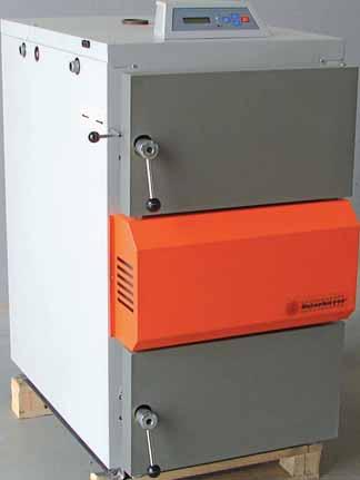
3 1 Control Simple controller for efficient burn cycle 2 Large fuel chamber door 3 Forced draught fan A variable speed motor supplies the air needed for the gasification process in the boiler. 4 Bottom door Easy access to bottom of the boiler for cleaning 5 Fuel chamber For logs sizes from 50 cm up to 100 cm (depending on boiler type) 6 Primary air duct Pre-heated air is added through the air channel at the back, to achieve clean combustion. 7 Ceramic nozzle with secondary air duct Brings about the right air to gas mix, which creates the best possible flame 8 Combustion chamber Made of high temperature resistant fireclay bricks, to complete gasification process which results in minimal amount of ashes 9 Ash chamber 10 Exhaust gas heat exchanger with turbulators For best energy transfer to the heating system 11 Damper To be used when lighting up the burner (Draft Regulation) 12 Safety Heat Exchanger Will cool down boiler in case of overheating 13 Boiler flow-line 14 Boiler return-line 15 Chimney flap with exhaust gas sensor Upper Fire Box Gasification at the jet in the Lower Chamber 12 Inside the burner Solarbayer GmbH 3
4 Contents 1 Sizing your Boiler 6 2 General Information SOLARBAYER boiler 2.1 Technical Description Construction Technical Details Dimensions Boiler Diagram 9 3 Safety Regulations 3.1 Mounting and Setup Safety Measures - Fire Protection Safety Instruction for Operation and Maintenance 11 4 Additional Equipment for SOLARBAYER boiler 4.1 Safety Heat Exchanger Boiler Circuit Pump, Laddomat Induced draught fan (optional) 15 5 Main Parts of the SOLARBAYER boiler 5.1 Adjusting the Doors Door Seal of the Fuel Chamber Cover plates of the Boiler Body Installation of the turbulators Forced draught fan Secondary Air Adjustment Fireclay bricks in the Combustion and Ash Chamber Nozzle and Linig made of Refractory Bricks Primary and Secondary Air Ducts Safety Temperature Limiter STB Boiler Control Unit Sensor Parameters 26 6 Control Menu 6.1 Directions for Use Flow Chart of the Control Unit Presetting and Changing of Parameters Adjusting the Boiler Temperature Adjusting the Switch Off Temperature Setting the Time Adjustment of the SOLARBAYER-Abgastronic Adjusting the Exhaust Gas Temperature Adjusting the Minimum Fan Speed Selecting the Burner Type 36 4 Solarbayer GmbH
 37 8 Initial Operation of the SOLARBAYER boiler 8.")


5 7 Control Unit of the SOLARBAYER boiler 7.1 Factory Settings (standard settings) 37 8 Initial Operation of the SOLARBAYER boiler 8.1 Heating Up the Boiler Refuelling the Boiler Shutting off the Boiler Heat Value Chart / Storing of Firewood 43 9 Boiler Maintenance 9.1 Cleaning the Boiler How to Measure the Exhaust Gases Boiler and Exhaust Gas Temperatures during Operation Maintenance and Repair of the Boiler Trouble Shooting Technical Service 12.1 Software Adjustment Wiring diagram 56 Warranty 58 Declaration of Conformity 59 Solarbayer GmbH 5
6 1. Sizing the Boiler Please note that the boiler output specified can only be achieved under full load. To heat up the boiler will take approx. 30 min until full load is reached. The boiler output is kept for a period of approx. 2 hours, after that the burn-out phase follows with reduced output for a period of approx. 1.5 hours. The residual embers in the combustion chamber coasts the temperature for about one more hour, after that the fuel is completely used up. Hence, the duration of the burn cycle is approx. 4 hours. The boiler will be heated up in the morning and in the evening, thus a burning time of approx. 8 hours is achieved. Warning: This is imperative for the rating of the boiler to avoid that the boiler output is rated too weak. Rough estimate of boiler size by means of living space: Example: building with 150 m² living space desired boiler size Solarbayer 25 kw required heat output per square metre living space* Old building 0.12 kilowatt per m² New building 0.08 kilowatt per m² Low energy house 0.05 kilowatt per m² Calculation of the daily output of the building e.g. living space 150 m², e.g. new building => 0.08 kw/h per m² 150 m² x 0,08 kw/m 2 = 12 kw The hourly output for the new building with an outdoor temperature of -16 C results in 12 kw/h Daily requirements 24 hrs x 12 kw =288 kwh The heat output required at -16 C outdoor temperature is 288 kw per day. Calculation of the boiler output: e.g. SOLARBAYER 25: Output 25 kw x 4 hrs (full load) = 100 kwh The burning-down heat output of a 25 kw solid fuel boiler at approx. 4 hrs full load results in 100 kw. 288 kwh : 100 kw h (burning-down heat out- = 2,88 boiler fillings Daily requirements of the new building put) to achieve the necessary heat output of the building With this building you must fill the boiler around 3 times per day with an outdoor temperature of -16 C. An average of 2 fillings per day should be sufficient.. This calculation is for general information only and does not replace professional design! * If the boiler is dimensioned too small you will achieve boiler temperatures of C, but the desired heating supply line temperature will not be achieved, e.g. building size 220 m 2 old building: boiler output 25 kw (wrong rating!) Correct would be SOLARBAYER 50kW. 6 Solarbayer GmbH
7 2. General Information SOLARBAYER boiler 2.1 Technical Description Thermal boilers SOLARBAYER15, 25, 40, 50, and 80 are designed for the combustion of dry wood, starting from sawdust up to logs, length corresponding to the size of the fuel chamber, max. length 14 cm. Sawdust, chippings and wood splinters need to be burnt along with wood logs. The interior of the boiler consists of a fuel chamber where the fuel is dried and gasified. The wood gas developed is led through a fire resistant jet into the combustion chamber where it starts burning by means the addition of secondary air. Waste gases are intensively cooled down in the heat exchanger. The unburned waste products shall be swept out of the combustion chamber. For heating up the boiler is equipped with a damper which is operated by a connecting rod at the front of the boiler. For smooth operation the boiler is provided with a logically and user-friendly structured control unit. 2.2 Construction The boilers are made of 4 and 6 mm thick steel panels which are welded together. The inner steel parts which are in direct contact with the waste gases are 6 mm thick. The heat exchanger consists of welded steel tubes, diameter 57 x 5 mm. The heat exchangers are single-row (boiler types SOLARBAYER 15, 25, 40) or two-row (boiler types SOLARBAYER 50, 80) depending on boiler size. Standard SOLARBAYER boilers are provided with a safety heat exchanger to prevent overheating. The thermal safety valve has to be connected to it (cf. chapter 4.1). The safety heat exchanger is made of a copper tube, diameter 18 mm and permanently installed. The boilers welded at robot production places are welded together by using MAG-technology. The boiler covers are made of powder-coated steel sheet. The lower combustion chamber is lined with standard fireclay bricks P4 (40 mm thick). The floor of the fuel chamber is filled with fireproof mortar. The replaceable heat-resistant jet is made of fireproof material. Boilers of kw are equipped with a combustion air ventilator; from 50 kw onwards two ventilators are provided. A glass fibre door seal with a square cross section (25 mm) is used. As insulation of the heat exchanger cover glass fibre with round cross section (8 mm) is used. Thermal insulation of the boiler consists of insulation material NOBASIL (20 and 40 mm thick). Waste gases are removed through an exhaust air duct of steel, diameter 160 mm (SOLAR- BAYER 15, 25) and diameter 200 mm (SOLARBAYER 40, 50, 80). Hydraulic connection diagrams are displayed in our schematics handbook on Solarbayer GmbH 7
8 2.3 Technical Details effective boiler output in kw 14, nominal boiler output with performance control kw 3 bis 21 5 bis 31 8 bis bis bis 92 efficiency factor % height A mm height supply line B mm height return line C mm height drain valve D mm height exhaust pipe (center) E mm width incl. gate valve F mm width G mm depth H mm depth supply line I mm flue outlet Ø J mm distance to boiler edge K mm distance L mm recommende chimney diameter Ø mm required chimney draft Pa effective min. height chimney m max. operating pressure bar noise level db 45,5 45,5 47,7 51,4 54,2 waste gas mass flow at 13% CO2 kg/s 0,019 0,023 0,029 0,035 0,035 waste gas temperature C boiler connection inch boiler water volume Liter combustion chamber volume Liter chamber door access (w / h) mm 435 / / / / / 318 max. log length mm fuel volume beech wood approx. 20% res. moisture kg energy content beech wood kwh burning time beech wood h 6,3 5,1 5,4 6,3 6,9 heating of water from 45 C to 90 C (δt 45 K) Liter fuel volume fir wood aprox. 20% res. moisture kg energy content fir wood kwh burning time fir wood h 4,8 4,5 4,6 4,8 5,1 heating water from 45 C to 90 C (δt 45 K) Liter weight of boiler kg recommended min. buffer storage volume Liter Calculation of Buffer Volume: Recommended Per kw nominal boiler output at least 55 litres of buffer water are needed. A maximum of 100 litres per kw nominal boiler output must not be exceeded. Buffer storage tanks must be installed with each wood-fired boiler system. 8 Solarbayer GmbH Technical changes and errors are reserved

9 2.4 Dimensions Dimensions of the SOLARBAYER-Log Burner 2.5 Boiler Diagram SOLARBAYER 25 SOLARBAYER 40 SOLARBAYER Control 2 Upper door 3 Damper Control Rod 4 Fuel Chamber 5 Primary air duct 6 Fan flap 7 Fan 8 Fan cover 9 Ceramic nozzle 10 Secondary air duct 11 Door handle 12 Refractory bricks 13 Bottom door 14 Chimney flap 15 Heat exchanger cover 16 Damper control lid 17 Upper cover (rear) 18 Flow 19 Thermal safety valve assembly 20 Thermometer 21 Upper cover (front) 22 Heat exchanger pipes 23 Fireproof cladding 24 Secondary air duct 25 Combustion chamber 26 Direction of exhaust gas stream 27 Return water 28 Drain Solarbayer GmbH 9
10 3 Safety Regulations 3.1 Mounting and Setup The boiler can be only operated within a central heating system with a heat capacity corresponding to the output of the boiler. The assembly has to be performed according to the currently asserted DIN norms and regulations When using forced circulation the central heating must be designed in such a way that the minimum heat consumption of 5 kw of the boiler output is guaranteed in case of power failure (breakdown of shunt valve with pump - Laddomat). The pipelines to the buffer storage tank should be installed with automatic transition into gravitation flow. The boiler must be connected to the chimney in a workmanlike manner and by the shortest way. Do not install any further heating systems to the chimney. Only use thermal safety valves that are tested and registered according to DIN The boiler must be placed on a firm, load-bearing floor. The minimum temperature of the return line water at the boiler inlet must be 72 C. The room where the boiler is installed must be ventilated by means of a permanent opening with a diameter of at least 250 cm. Openings for air supply and air exhaust shall be around the same size. The boiler must be erected in a normal room 3.2 Safety Measures - Fire protection The boiler shall be installed in accordance with the applicable fire protection regulations. With regard to installation specified safe distances from combustible and inflammable materials and objects have to be observed. For thermal boilers with an output up to 50 kw the specified safe distance from combustible materials of class B, C1 and C2 must be at least 200 mm and of class C3 at least 400 mm in accordance with standard. The safe distance is reduced to half if a noncombustible thermal insulation board (asbestos board with a minimum thickness of 5 mm) is installed 25 mm from protected combustible material. The board shall project at least 150 mm above the outline of the boiler with smoke exhaust and above the upper surface of the consumer must be at least 300 mm free space. Material classification: Class A: non-combustible building materials (asbestos, concrete, mortar, brick, glass, fireclay, etc.) Class B: very hardly combustible materials (gypsum cardboard, etc.) Class C1: hardly combustible materials (lignite boards, chip boards in acc. with STN , etc.) Class C2: moderately combustible materials (wood oak, alder, larch, fir, wood chip boards, etc) Class C3: easily combustible materials (wood pine, beech, ash, poplar, wood fibre boards, cork, foil sheets, polystyrene, polyethylene, bituminous cardboard, pulp, plywood, etc) In case of any doubt the SOLARBAYER boiler has to be placed on a protective plate (see figure page 11).If there are any ambiguities please contact the appropriate regulating authority (i.e. district chimney sweeper). 10 Solarbayer GmbH
11 3.3 Safety Regulations for Operation and Maintenance The staff operating the boiler must observe the rules and regulations and standards in connection with operation: 1. During operation of the boiler, electrical equipment and cables of the boiler must not be intervened with, for example: removal of covers of electrical systems such as boiler electronics, ventilator, thermostat exchange fuses repair of damaged cable insulations, etc.. 2. Maintenance or repair work that requires removal of covers of electrical parts of the boiler must only be performed by the person entitles in accordance with publication No. 74/1996 of the compendium of laws. 3. Prior to removal of the covers of the boiler or an electrical device connected to the boiler it is necessary to switch off any mains supply. 4. If defects at the electrical installation or defects at the installation of the boiler are detected it is necessary to observe the following rules: do not touch boiler parts immediately disconnect the boiler from power supply; call the responsible service engineer to solve the problem 5. Heat-resistant cable placing according to VDE standard. Solarbayer GmbH 11
12 4 Additional equipment for SOLARBAYER boilers 4.1 Safety heat exchanger A thermal safety valve is laid down by DIN for solid fuel heating system. Use of the safety heat exchange: In case of power failure the thermal safety valve (thermostatic valve Watts STN 20)serves as boiler protection mean to prevent overheating. Assembly of the safety heat exchanger: The boilers are already equipped with the safety heat exchangers. The thermal safety valve (thermostatic valve Watts STN 20) will be delivered separately. Mounting of the Safety Valve STN 20: It is important, to fit the thermal safety valve in such a way, that, under operating conditions, the safety heat exchanger is depressurised and is not connected to the pressurised part of the heating system. The thermal safety valve has to be connected to the pressurised mains water line, without any means of shutting of the water supply (Stopcocks, valves, etc.). The drain side has to be run unobstructed into a gully or drain. Copper Pipe sealing for the Thermal Note: The thermal safety valve has to be fitted discharge safety valve before the system is filled or put into operation. Observe local guide lines. Function of the Safety Vale : The pressure independent valve opens when the flow temperature of aprox. 95 C is reached. By opening the valve, it will cause a constant drain of water which inhibits the temperature to rise above 110 C. NOTE: The galvanised nipple of the safety heat exchanger is attached with a washer seal to the copper pipes by screwing, if a water leak shall occur between the different fittings, tighten the galvanised nipple or replace the washer seal. 1 Outer boiler wall 2 Weld Seam 3 Weld neck socket 4 EPDM seal 5 Threaded nipple 6 Copper pipe heat exchanger 18mm 12 Solarbayer GmbH
, cold water input ❷ sensor pocket with")


13 ❸ ❷ ❶ Solarbayer 25 kw and 40 kw ❷ ❶ ❸ Solarbayer 50 kw and 80 kw ❶ thermal discharge safety valve (discharge valve Watts STN 20 ¾ ), cold water input ❷ sensor pocket with dual temperature monitor ❸ cold water output Please test the thermal safety valve at first use for operation by heating up the boiler to opening temperature. Thermal discharge safety valve Note: According to DIN pt 10 you are asked to have an inspection carried out by a suitable qualified person at least once a year. Solarbayer GmbH 13
.")
14 4.2 Boiler Circuit Pump, Laddomat Note: To run the boiler efficiently and to guarantee a long service live, it is important to operate the burner with a boiler return control that ensures a return temperature of 72 C to the burner. We recommend the Laddomat 21. Electrical Connection: Connect the boiler circuit pump to the connection rail on the control panel (see chapter 12.2 for layout). Maximum load 200 W. Function of the boiler circuit pump: Once the SOLARBAYER-log burner is switched on, the pump is activated to ensure a constant rising of the boiler temperature. When the boiler is switched off, the pump stops. In the event that the boiler temperature exceeds the set temperature (90 C) the pump switches on to prevent overheating. The operation status of the pump is shown by the LED diode on the display. In case of a malefunction or fault of the temperature sensor, the pump switches on! Warning: Running the boiler without a thermal return control will result in the building up of condensation, which will lead to rapid corrosion of the boiler walls. For a clean and efficient combustion a boiler temperature between 75 and 90 C is necessary. This can only be achieved with the Laddomat. Laddomat 21 with temperature set at 72 C cover piston to buffer tank safety assembly spring thermostatic element Laddomat Solarbayer Boiler 14,9 kw to 80 kw plate for check valve from buffer tank expansion vessel for the boiler cover check valve spring 14 Solarbayer GmbH
.")


15 4.3 Induced draught fan (optional) The standard SOLARBAYER boiler is equipped with a forced draught fan. The electronic control enables the additional application of an induced draught fan (ID fan). The ID fan provides for the optimum removal of flue gases out of the fuel chamber during loading of fuel. Thus, no flue gas escapes out of the fuel chamber during loading. The ID fan is not included in the standard equipment of the boiler. It is available in sizes 160 mm and 200 mm as optional accessory. The ID fan for direct attachment to the flue pipe is suitable for all boilers. Correctly Installed ID fan (motor horizontal) Warning: Do not install motor vertically! Degasing the fuel chamber with the induced draught fan Exhaust Fan 90s boiler temp C + After pressing key + at the control unit, the Id fan is put into operation for 90 seconds. After pressing the key again further 90 s are added, maximum running time of theventilator is 300 s. Fuel can be refilled during the operation of the ID fan. Solarbayer GmbH 15
 600 Motor Speed (1/min) 2780 Output (Watt) 48 Mains Supply (V/Hz) 230/50 Protection IP 20 Weight (kg) 13 Max. Temp.")
16 Technical Data: The motherboard of the control unit holds a joint for the connection of the exhaust fan (see chapter 13.2 for wiring diagram) Technical Data Induced Draught Fan Max. Temperature ( C) 600 Motor Speed (1/min) 2780 Output (Watt) 48 Mains Supply (V/Hz) 230/50 Protection IP 20 Weight (kg) 13 Max. Temp. Motor ( C) 80 Overall length A 385 mm Width 235 mm Height with Motor C 247/280 mm Exhaust Inlet/Outlet D 70 mm Outlet/ Inlet Diameter 160/200 mm If the exhaust gas formation is too high while refuelling the boiler and therfore leads to unpleasant odours, we recommend the installation of an induced draught fan. The retrofitting is easy to handle. An electrical connection is pre-installed. Note for correct sizing of expansion vessel: Dimensioning of the expansion vessel (10% of heating water volume) e.g litre heating water = 200 litre expansion vessel. Warning: The expansion vessels are factory-preset to 1.5 bar diaphragm pressure. It is necessary that the vessels are adjusted to the height of your installation. Measure the installation height of your house, from the basement to the topmost radiator. Example: installation height 7 metres + 2 metres extra = 9 metres. 9 metres correspond to 0.9 bar diaphragm pressure at the expansion vessel. The vessels need to be checked every 2 years by relieving the heating pressure and measuring of the diaphragm pressure. Afterwards the cold heating installation must be filled to 1.2 bar. During heating up the heating pressure will increase a little and drop again during cooling down. 16 Solarbayer GmbH


17 5. Main Parts of the SOLARBAYER Boiler 5.1 Adjusting the doors The boiler doors are fastened at three points: at two turning pins and the closure. If the doors are not tight enough they can be adjusted at the hinged side. If the nuts are loosened, the hinge screw can be turned and the door pushed into the direction wanted. afterwards, retighten the nuts again. Parts of the Door Hinge pin Thread Nut Nut with welded Shim Split Pin Hinge hole Washer Bracket Parts of the Closing Handle Head Thread Handle The threads of hinge and handle must be greased on occassion. Solarbayer GmbH 17


18 Adjustable hinge at the right side of the boiler Fastening plate welded on to the boiler body 5.2 Door Seal on the Fuel Chamber Replacement of thermal insulation 1. Open door completely 2. Find the joint of the insulation at hinged side of the door using a screw driver. 3. Remove the hardened insulation gradually using a screw driver 4. Match the ends of the old or new sealing cord and press them in the groove between the hinged joints starting in the middle. Distribute the remainder of the insulation evenly to the sides and press it together in the middle. 5. If there are leakages put some heatresistant silicone into the groove at the corners. 6. Always start in the middle in direction of the corners when inserting the door insulation Take care, that the insulation is not turned round and that the corners are filled well. Location of sealing cord joint The doors, like the boiler, consist of the insulations and a sheet-metal covering Attention: As the inside of the door is made of heat resistant concrete care must be taken that the upper door is not used to press the fuel into the boiler because this leads to damage of the lining. Damaged lining should be removed and replaced. Adequate mortar is available at SOLARBAYER. Prepare the mortar mixture not before starting the repair work. If prepared use immediately. The setting time of 24 hours has to be respected. 18 Solarbayer GmbH

19 5.3 Cover plates of boiler body The cover plates of the boiler body are made of powder-coated steel sheet and treated with fired colour to protect the plates from corrosion. Three colours are used: grey, silver and SOLAR- BAYER-orange. Grey is used for the cover plates of the upper and lower doors, the ventilator casing is varnished with SOLARBAYER-orange and silver is used for the remaining jacket of the boiler. The upper front plate needs to be dismantled for the entry of the thermostatic sensor. To dismantle this plate, the two self-cutting screws at the front must be loosened first. Then you remove the cover caps located at the corners of the upper front plate with a slot-head screw driver. Below the cover caps are self-cutting screws which shall only be loosened. At first, you push the upper front plate 2 cm to the front and then you tilt it carefully from the front to the back. Note: Prior to removal of the boiler jacket or one of the electrical devices connected to the boiler, all cables must be disconnected from the mains supply. The side cover plates shall be dismantled as follows: At first, the upper front plate must be removed as described above. Then the upper plate at the back needs to be dismantled. The upper and lower boiler door must be tightly locked. To dismantle the cover plate on the hinged side the nuts pressing on the galvanized shims shall be loosened. When dismantling the plate on the closure side the two screws located under the closure of the door shall be removed. Then the ventilator casing shall be removed. At the back side all self-cutting screws shall be removed and then the two side cover plates can be dismantled. The door cover plates shall be dismantled as follows: at first, the entire doors shall be dismantled in such a way that the pin can be pulled out of the hinge. The closure of the door shall be dismantled. The doors shall be laid down in such a way that the interior side lies on the floor. The cover plate of the long sides shall be pulled out and laid down. The cover plate is only put on to the doors. Solarbayer GmbH 19


20 5.4 Installation of turbulators The turbulators which are delivered along with the gasifying wood log boiler can be installed in the exhaust gas heat exchanger ducts (see picture) when needed. Recommendation: The turbulators should be installed when heating with dry, untreted wood with little resin. When heating with either very resinous wood and/or residual wood the turbulators should not be isntalled. To clean the exhaust gas ducts the turbulators have to removed, afterwards they can be installed again. Number of turbulators required: HVS 14,9 to 40 6 turbulators HVS 50 and turbulators 5.5 Forced draught fan SOLARBAYER boilers are constructed as overpressure boilers, i.e. the air volume required for combustion is supplied by forced draught fans. Boilers, type 15 40, are equipped with one forced draught fan, in boiler types 50, 80 two fans are installed. The fan consists of 4 basic parts: 1. Fan casing made of aluminium alloy 2. Motor 3. Capacitor 4. Fan wheel Note: A dust free and clean environment is the basic condition for the reliable operation of the ventilator. Therefore, it is necessary that the fan is regularly checked and serviced. If the noise level becomes more intensive, dust from the blades of the propeller should be removed. Dust on the blades results in noisy operation and leads to decline in the technical parameters and thus to lower boiler output and worse emission values. Prior to replacement or dismantling of the fan all power cables must be disconnected from power supply. Then the cover plate shall be dismantled. With boiler types SOLARBAYER 40, 50, 80, 100, access to the screws is easy and it is possible to remove the plate below the ventilator in order to reach the screws. The fans installed in boilers SOLARBAYER 15 and 25 are provided with an intake guard plate to reduce the air volume required for combustion. This guard plate can be only found in ventilators with metal sheet propellers. The guard plate is not necessary for plastic propellers 20 Solarbayer GmbH

21 5.6 Sheet metal base for forced draught fan, ventilator damper, adjustment of secondary air The sheet metal base for the ventilator is a plate onto which the forced draught fan is mounted. A part of this plate is provided with screws for the regulation of the secondary air volume and the ventilator damper. The plate is fastened to the boiler body with self-cutting screws which are located all around the plate. Behind the ventilator is a safety damper which protects the forced draught fan from back pressure and prevents self-ignition of the fuel in case of high chimney draught. Note: In case of insufficient air pressure in the fuel chamber the function of the ventilator damper needs to be checked. In order to guarantee optimum combustion in the boiler correct, adjustment of the secondary air is very important. The procedure is as follows: at first, the fastening nuts at the screws must be loosened and then the screws need to be turned clockwise by means of a slot-head screw driver all the way to the stop. Afterwards, the screws shall be turned anticlockwise in 2 3 turns. Adjustment of the secondary air shall be carried out every time the sheet metal plate is placed below the ventilator or when the insulation beneath the plate is replaced. Small air draught can Ventilator she lead to incomplete combustion, high air draught to a so-called cracking/popping inside the boiler. The adjustment of the secondary flow has to be carried out before first commission and, if necessary, adjusted according to the particular chimney draught conditions. SOLARBAYER 15,25, 40 ( Model 50 and 80 are equipped with two fans) Ventilator sheet metal plate Air Flow Adjustmet Plate Adjustment Srews for secondary air flow The fans used in the SOLARBAYER-boiler 15 and 25, are fitted with an intake protection plate which is used to regulate the air flow, to adjust the power output. Solarbayer GmbH 21


 which have to be placed underneath the combustion chamber.")

22 5.7 Fireclay Bricks in the Combustion and Ash Chamber Combustion chamber bricks: The refractory bricks are only loosely adjusted in the combustion chamber, as you can see beneath Attention: the refractory bricks have to overlap the edge of the combustion chamber. If the refractory bricks are adjusted incorrectly, the fire hits the edge of the combustion chamber unopposed and might damage the steel tank prematurely. A deformation or a melting loss of the steel tub does not affect the performance of the boiler and therefore it is not a defect. Ash chamber bricks: To protect the boiler s ash chamber against high heat influence and possible damages, the Solarbayer boiler are equipped with 2 fireclay bricks (boiler type 40, 50 and 80) which have to be placed underneath the combustion chamber. While cleaning the ash chamber, the fireclay bricks have to be removed and afterwards positioned correctly again. The ash chamber bricks as well as the combustion chamber bricks are wearing parts and have to be exchanged when needed. Suitable bricks are available at SOLARBAYER. Mind the overlapping fireclays (approx. Position of the 10 mm) combustion chamber bricks in the steel tub (example: HVS 25) 22 Solarbayer GmbH


23 5.8 Nozzle and Lining made of Refractory Concrete The nozzle is a formed part of fire-resistant concrete and provides for the mixing of flue gases with secondary air which results in absolute combustion. The nozzle is located on a grate cooled with water. The seat of the nozzle is lined with refractory mortar up to the height of the nozzle edge. The service life of the nozzle is dependent on mechanical damage during putting on fuel and raking of fuel. For this reason, the nozzle is considered as consumable part and can be replaced. The nozzle should be replaced only in case of a complete breakdown. Cracks in the nozzle are no reason for its replacement. The pyramid shape makes replacement relatively easy. If the nozzle is damaged, the remaining parts of the old one need to be removed. Afterwards, a new nozzle shall be installed into the opening. Please, check if the new nozzle fits well into the designed opening. If it does not fit exactly, the opening shall be adapted and not the nozzle. After installation of the nozzle the permeability of the individual holes shall be checked. Secondary Air 5.9 Primary and Secondary Air Ducts By primary air ducts the supply of the necessary air volume from the ventilator into the combustion chamber is guaranteed. It is provided as the so-called rear air duct. The advantage is better heating of primary air. When the plate below the ventilator is removed the primary and secondary air lines are accessible. The ducts at the edge lead the primary air, the inner ducts the lead the secondary air into the nozzle. Primary air volume is not regulated but dependant on the ventilator type. jet primary air channel secondary air channel Rear Air Ducts Solarbayer GmbH 23
. Interference signal! flashes. ERROR M A X. T E M P.")

24 5.10 Safety Temperature Limiter STB A safety temperature limiter is connected to the control board. In case of overheating, boiler temperature higher than 95 C, the forced draught fan is switched off from the connection (230V/50Hz). Interference signal! flashes. ERROR M A X. T E M P. Pressing the key I displays Pump LED flashes (is operating) After cooling down to less than 90 C the STB can be unlocked again by pressing I Another possibility is to unlock the STB manually at the display casing. Release the black cover and press the green safety button. The boiler is ready for operation again. Possible reasons for overheating are: The problems have to be solved immediately. - a broken boiler circuit pump - a closed valve - air in the system - maximum boiler temperature is achieved STB-safety temperature limiter Possibilities to unlock the STB 5.11 Boiler Control Unit SOLARBAYER boilers are always provided with Abgastronic The control unit s basic principle consists in temperature regulation of the heating water being released by the boiler and of the exhaust gas temperature. The desired temperature is reached by air volume control which is carried out by continuous control of the fan capacity. The control unit consists of three electronic modules: - the control unit with LC display, LED display and 4 keys - the motherboard, named AK 2005 S, controls the electronic parts such as the forced draught fan, circulating pump, etc. - SOLARBAYER Abgastronic module AK 2000 MMKT The control unit is solidly installed in the boiler cover plate. The control board and the exhaust module are installed onto a 35mm DIN rail. Mains voltage exists only in module AK 2005 S, the control unit with its LC display is electronically isolated from the mains voltage and supplied with safe 9 V DC power. 24 Solarbayer GmbH

 motherboard exhaust module")
 Control unit with display (rear and front")
25 All electric parts of the SOLARBAYER boilers are installed at the strip terminal of the control board. For terminal layout see chapter 12.2 (wiring diagram) motherboard exhaust module exhaust sensor burner sensor control unit (rear side) Control unit with display (rear and front view) Solarbayer GmbH 25
.")

 exhaust gas sensor Solarbayer PT1000/600 26 Solarbayer GmbH")
26 5.12 Sensor parameters To monitor the temperature in the burner a KTY 2000 type sensor is used. The sensor is connected straight to the display (small plug).the performance of the sensor is shown in the graph below. (i.e. 25 C Ohm) boiler sensor KTY2000 A Solarbayer-PT 1000/600 type sensor is used to detect the exhaust gas temperature, which is connected to the AK 2000 MMKT controller. The performance of the sensor is shown in the graph below. (i.e. 25 C 1000 Ohm) exhaust gas sensor Solarbayer PT1000/ Solarbayer GmbH

 To vent the fuel chamber without the exhaust fan - (see chapter 8.1) Factory setting is basic menu, after 100 secs idle it will return to basic menu as well.")
27 6 Control Menu 6.1 Directions for use Refueling Roomstat (optional) Boiler Pump Error Indicator On the control panel are four pressure keys: Menu key; to enter into the setup menu and submenu. F To confirm entered values. I To switch burner on or off. To escape the submenu to the next level menu. In the main menu and its submenus: Parameter selection and increase or decrease the adjustable values + - In the basic menu : To activate the induced draught fan Optional ; + (see chapter 8.1) To vent the fuel chamber without the exhaust fan - (see chapter 8.1) Factory setting is basic menu, after 100 secs idle it will return to basic menu as well. To leave the main menu and its submenus, press key displayed I repeatedly until basic menu is The parameter in the menu can be called upon with key - or key + Values which are flashing can be adjusted; with key - or key + After altering a value confirm new value with key F Solarbayer GmbH 27
28 6.2 Flow Chart of the SOLARBAYER-Abgastronic control unit Boiler off Basic Menu I F Basic menu Setting temp. F Parameter: Heating, Program, and Decrease can be selected Select with key + or Basic menu Configuration + - F Parameter Language English, Combustion wood, Shut down and Service can be selected Select with key + or - Basic menu Time setting F Select parameter Day and time Select with key + or Solarbayer GmbH
29 6.3 Presetting and Changing of Parameters The burner is pre-wired, only the Laddomat-Pump of the return flow increase and the ID fan motor have to be wired on site. All settings are factory preset, the burner is ready for use. Short overview of the SOLARBAYER factory settings: Preset Values Parameter Factory Setting Changeable from Up to Boiler Temperatue 85 C 65 C 90 C 90 C Program S 1 10 (=S) S Reducing Value 30% 20% 40% 30% Solarbayer- Recommended Your setting Switch off Temperature (Exhaust gas temperature) 50 C 35 C 150 C 80 C Service Settings Exhaust Gas Temperatuer 150 C 150 C 250 C 180 C Fan Speed 42% 3% 69% 42% Type of Burner Program The Attention: Parameter The values are highlighted listed and in explained yellow are on pre-set the following for systems pages. with buffer storage tanks. Do not alter! Service data changes are carried out under Code (see chapter 6.4) Solarbayer GmbH 29
30 6.3.1 Adjusting the Boiler Temperature The boiler temperature is the temperature that shall be reached and maintained in the boiler in relation to the set exhaust gas temperature. Basic menu Setting temp. F Press key boiler temp. Heating 90 C F Press key boiler temp. Heating 90 C F Confirm with key, display starts flashing + - Press keys to adjust temperature between C Preset = 90 C We recommend 90 C F Confirm with F key, display stops flashing The boiler temperature is set. In a cold boiler the permitted exhaust gas values cannot be maintained, therefore the boiler temperature has to be set between 80 and 90 C. Only with this setting an optimal combustion is possible. 30 Solarbayer GmbH
31 6.3.2 Adjusting the Switch Off Temperature The switch off temperature defines the temperature value in the exhaust gases. The boiler will be switched off if it falls below that value. Basic menu Setting temp. F Press button In the main menu press keys + or - until Basic menu Configuration is displayed Configuration Language English F Press button. Press + or - until Configuration Shut down C is displayed Configuration Shut down C F Confirm with button Value starts flashing. + - F With the keys, up or down, select temperature from C Preset = 80 C We recommend 80 C Confirm with button. Value stops flashing. Switch Off Temperature is set. Solarbayer GmbH 31
32 6.3.3 Setting the Time The date and the time can be set in the Time Setting menu. Once the burner is switched on for the first time and after a power failure the clock has to be set. After mains supply, key! flashes. After pressing F the display shows error massage : ERROR SLEEP Date and time have to be adjusted Basic menu Setting temp. F Press key In the main menu press + or - until Basic menu Time setting is displayed Time setting 10:02 F Press key to confirm Week day starts flashing; adjust with + or - confirm with F Hour setting starts flashing. Adjust hours the same way as the day and repeatfor minutes. Confirm each setting with F To go back in to the Basic Menu press I 32 Solarbayer GmbH
33 6.4 Adjustment of the SOLARBAYER-Abgastronic To change the parameters exhaust gas temperature, minimum fan speed, boiler type and the program of the SOLARBAYER-Abgastronic, go to the password mode. To enter it, please follow the steps shown below. Basic menu Setting temp F In the main menu press keys + or - until Basic menu Configuration F is displayed Configuration Language English F press key + - press both keys simultaneously, until dislpay shows Configuration Password: 0 press key + until code Password 111 is dislpayed Password setting Boiler type 0 F press key now you entered the Service Level with key + and - select parameters. Solarbayer GmbH 33
34 6.4.1 Adjusting the Exhaust Gas Temperature The exhaust gas temperature defines the desired value, which has to be reached and maintained. An average exhaust gas temperature is picked up by the sensor in the flue opening. Because of the position of the sensor, the temperature can read about 20 to 50 degrees higher for short period of time. This fact is given by the changing flow of the core of the exhaust gases which does not allow measuring the core temperature correctly. (see picture). Kernstrom To change the exhaust gas temperature go into the password mode.( see previous page) Press + or - until Password setting Max spaliny 180 C is dislpayed (Spaliny is the exhaust gas temperature) Password setting Max spaliny 180 C F Press key + - Use keys to adjust "Max spaliny C" from C Factory setting = 180 C We recommend 180 C F Press to confirm The exhaust gas temperature is now set. 34 Solarbayer GmbH
35 6.4.2 Adjusting the Minimum Fan Speed The minimum fan speed is to be changes in the password mode. To get into the password mode see chapter 6.4. The minimum fan speed defines the power of the fan at its lowest setting. The setting can be adjusted in between 3% to 69%. Factory setting is 42%. In service mode press + or - until Password setting Min.speedfan 42% appears on the display. Password setting Min.speedfan 42% F press to confirm. original value starts to flash. + - F with + and - buttons set the new value "Min.speedfan %" between 3% - 69%. SOLARBAYER - Setting = 42% press F to store. The new minimum fan speed is now set Solarbayer GmbH 35
36 6.4.3 Selecting the Boiler Type Go to the password mode to change the boiler type. (see chapter 6.4 ) The SOLARBAYER control contains two different boiler types Type 0 standard boiler SOLARBAYER Type 1 pellet boiler SOLARBAYER The SOLARBAYER-Controller is preset to Type 0. Press key + or - in the password mode until password setting Boiler type 0 is displayed password setting Boiler type 0 F to confirm press key Display starts flashing + - F use keys to select type 0 or 1 Solarbayer-Setting 0 To confirm press key The boiler type is now set 36 Solarbayer GmbH
37 7. Control Unit of the SOLARBAYER boiler The electronic control unit AK 2000 enables changing and adjustment of the control of SOLAR- BAYER boilers and the hydraulic integration into central heating installations. Changes in the control software are made by using a password. 7.1 Factory settings (standard settings) Program 16 with SOLARBAYER Abgastronic The programme is designed 1 SOLARBAYER boiler 6 Exhaust fan 2 Safety valve 7 Buffer tank for the control of boilers in 3 Expansion vessel boiler 8 Exhaust sensor combination with stratification 4 Expansion vessel buffer tank 9 Heating circuit systems. After the selection of 5 Laddomat 10 Domestic Water the programme the boiler is not switched off by the temperature of the outgoing water but by the temperature of the waste gas in the chimney. It is possible to select the shutdown temperature in the configuration program: from 50 C to 150 C (recommended: 80 C). The desired boiler temperature can be selected in the menu for temperature settings: from 65 C to 90 C (recommended 90 C). This is standard with SOLARBAYER boilers. Description of Operation: The boiler switches from heating-up to heating operation if the exhaust gas temperature is higher than the desired boiler temperature of +30 C. But only on condition, that the boiler has been switched on more than 30 minutes ago. The boiler controls the exhaust gas temperature when heating; if the temperature falls below the value set in the switch off menu the boiler turns off. The period of 5 minutes provides for bridging a possible temperature decrease during the shift from the damper to the heating system by the heat exchanger. A temporary increase of the exhaust gas temperature might occur due to a cold heat exchanger. Circulation Pump - On: The circulation pump immediately starts when the boiler is turned on for a constant heating up of the boiler. Circulation Pump - Off: The pump is switched off when the boiler is switched off. The exhaust gas temperature (switch off) switches off the boiler and the pump. However, if the boiler temperature exceeds the desired temperature (e.g. 90 C) the pump switches on to prevent overheating. For electrical wiring diagram see attachment Solarbayer GmbH 37


 and remains of the burned wood of the day before onto the nozzle.")
38 8. Initial Operation of the SOLARBAYER-boiler 8.1 Heating Up the Boiler Prior to heating it is necessary: to get familiar with the electronic control unit to check the water pressure of the central heating to check the connection of the boiler to the mains supply to check the operability of the boiler circuit pump to check the correct position of the refractory bricks in the combustion chamber to check the settings of the secondary air (see chapter 5.5) Heating up the burner : 1 Push the rod of the damper into position Anheizen/Auf 1 2 Remove the ash content in the fuel chamber and free the nozzle of all debris using the poker. 2 3 Put a handful of firewood (splinters) and remains of the burned wood of the day before onto the nozzle. Put some small logs, rumpled newsprint and a fire-lighter on top and light the fire. 3 Now close top chamber door Keep bottom chamber door slightly open at this stage 38 Solarbayer GmbH


39 (only when an ID fan is connected) Exhaust fan 90s boiler temp. C + Press key The exhaust fan runs for 90 sec. The fume outlet can be extended up to 300 sec by further pressing of the key. The induced draught fan should be running until the boiler is switched on. 4 Let the fire burn for about 5 to 10 minutes until proper embers can be seen. Now you can fill the fuel chamber with logs. 4 5 Once the flame can be heard (slightly hissing, blazing) you can close the boiler doors and push the rod into position Heizen/Zu 5 Attention: ALL DOORS have to be CLOSED. 6 Press key to start heating up. The ventilator operates and the combustion process begins. I The boiler is now heated up, at a temperature of 72 C the return flow increase opens and the heat is transferred to the buffer tank by the boiler circuit pump. During combustion, the fuel in the boiler moves towards the firebed. The ash falls through the nozzle and deposits in the combustion chamber. The output of the boiler is automatically controlled by the pre-set temperatures. The burner shall not be left unattended during the process of heating up. Solarbayer GmbH 39
40 SOLARBAYER recommendation: The electronic control unit is delivered with factory settings and pre-wired. It is only the boiler circuit pump of the return flow increase (e.g. the Laddomat 21) and the optional ID fan that have to be wired at the designated strip terminal. We recommend to leave the boiler temperature set at 90 ; this achieves an optimal gasifying effect and the best efficiency. The exhaust gas tract remains cleaner and ash formation is rather low (for settings see chapter 6.3.1) We recommend leaving the exhaust gas temperature at 80 C, to maintain the firebed over a longer period of time (for settings see chapter ) The most common reason for malfunctions is air in the heating system constraining circulation. With easy piping, like displayed by the diagrams in the appendix, the air can exhaust on its own. Please use our piping diagrams and our storage systems, as well as our Laddomat for best return flow increase. Well adjusted systems guarantee functional boiler technics. These are only tips for heating, please keep in mind that you are heating with a natural product. The wood has to be stored air-seasoned for at least two years. Dry heating material is the basic requirement for an almost smokeless combustion. 40 Solarbayer GmbH
41 8.2 Refuelling the Boiler Boiler off boiler temp C The boiler is not operating and the fuel control light flashes. The boiler has to be refuelled if more heat is required. It is also possible to refuel the boiler during the burning cycle. Care has to be taken when opening the fuel chamber door, to avoid smoke exit from the boiler. With chimneys below 8 meter we recommend to install the optional available induced draught fan. But you can also refuel the boiler without an ID fan. Attention: Make sure that the damper is open (in position Anheizen/Auf ) to insure proper draft. The timber logs have to be placed in the fuel chamber in such a way that the fuel chamber door can still be closed. A forcibly closing might damage the door lining. We recommend that the boiler should only be operated by persons over 18 years of age. Refuelling without induced draught fan boiler off boiler temp. C I Press button => boiler switches off Ventilation 15s boiler temp. C - press once => fan runs for 15 sec. Each time the button is pressed again, another 15 sec is added to the running time off the fan. To avoid smoke rising out off the burner, open door slightly and wait for a few seconds, before fully opening the fuel chamber door. Ensure doors are closed correctly after refuelling. Burn-up TURBO boiler temp. C I Press button to start boiler again Before refuelling the boiler open the damper (set to Anheizen/Auf position) After closing the fuel chamber door close damper (set to Heizen/Zu position) Solarbayer GmbH 41
42 Refuelling the boiler with induced draught fan optional The SOLARBAYER Log Burner comes with a forced draught fan as standard. The electronic control enables the additional connection of an induced draught fan. The ID fan supports the optimal withdrawal of the fumes out of the fuel chamber when refuelling the boiler. Fumes do therefore not escape through the open door when refuelling. The ID fan comes as optional equipment and is available in two sizes, 160 mm and 200 mm (depending on boiler size). Boiler off boiler temp. C I Press key, burner is off Exhaust fan 90s boiler temp. C + Press key. Exhaust fan switches on for 90s. Each time the key is pressed, the time will extend by 90 seconds up to a maximum of 300 seconds. Open the bottom door slightly and wait before open the door fully, to prevent the exit of smoke into the room. Close all doors fully and tight after the boiler has been refuelled. Burn-up TURBO boiler temp. C I Press key Boiler starts the heating up phase It is possible to refuel the boiler during the heating process. When the ID fan is operated the forced draught fan is switched off automatically. 8.3 Shutting off the boiler Boiler off boiler temp. C Boiler off boiler temp. C I Automatic shut off: The boiler is shut off when the exhaust gas temperature is lower than the preset switch off temperature. The yellow LED diode is lighting, the display shows boiler off. Manual shut off: Press key. If heat requirement does no longer exist and the boiler has to be refuelled no more the boiler can be shut off. NOTE: If the boiler is shut off manually and restarted the boiler program Burn-up TURBO is activated. If the boiler is not refuelled and the exhaust gas temperature is already below 120 C the boiler cannot be shut off automatically. The boiler has to be shut off manually after the combustion. 42 Solarbayer GmbH
43 8.4 Heat Value Chart / Storing of Firewood moisture content in % 10 % 15 % 20 % 25 % 30 % Type / Density 1) Unit Heat Value in kwh spruce kg 4,61 4,32 4,02 3,73 3, kg TM/fm fm rm Pine kg 4,61 4,32 4,02 3,73 3, kg TM/fm fm rm Birch kg 4,43 4,15 3,86 3,58 3, kg TM/fm fm rm Oak kg 4,43 4,15 3,86 3,58 3, kg TM/fm fm rm Poplar kg 4,43 4,15 3,86 3,58 3, kg TM/fm fm rm ) values in kg dry residue (TM) per solid cubic metre (fm) Storing of split timber Freshly cut timber contains between 45 to 60% water. With log wood boilers, however, you can only use timber with a maximum moisture content of 20%. Therefore, it is necessary to dry (season) the timber before use. We recommend the following for an optimal storing of split timber: store stack of woods protected from rain split into logs before storing create dry ground for storing and keep of the ground to ensure air circulation (e.g. pile on long timbers, etc.) store in wind exposed places if possible (e.g. at the edge of the forest not inside it) when stored closed to buildings ensure gap is left between buildings and logs, try to store logs south facing, put daily requirement of logs in heated rooms (e.g. boiler room to preheat the fuel!) when stored in buildings without special fire protection equipment you have to regard the maximum allowable amount of fuel Solarbayer GmbH 43


44 9. Boiler Maintenance 9.1 Cleaning the boiler If dry wood is used and the minimum temperature of the return water is kept at 72 C the contamination in the fuel chamber, the combustion space and the heat exchanger will be kept at a minimum. Cleaning of the fuel chamber (gasification chamber) The formation of tar in the fuel chamber (gasification chamber) is a usual effect. We recommend to burn the tar under controlled conditions with slightly opened upper boiler door and heatingup damper. Since the interior walls of the boiler are provided with an aluminium paint coat tar should not be scraped off (applies to SOLARBAYER 25, 40). Primary Air Ducts New fuel chamber The fuel chamber after a few days of service. The formation of tar is absolutely normal and is going to be burned off with the regular fuel. You have to clean the primary air ducts if they are blocked. An excessive quantity of ash in the fuel chamber which does not fall through the nozzle into the combustion chamber has to be removed. Ash and dust in the combustion chamber are removed with the scraper. If necessary, the ash in the combustion chamber is to be removed once a week. Cleaning of the fuel chamber (the picture shows the cleaning of the nozzle) delivered along with the boiler: Scraper Poker Round scraper 44 Solarbayer GmbH
 fuel is used.")

 Loosen the cover of the heat exchanger")
45 Cleaning the heat exchanger The pipes of the heat exchanger need to be cleaned once a month. The cleaning period extends itself when the ideal (dry) fuel is used. For the cleaning of the heat exchanger it is necessary to remove the cover to provide access to the pipes of the heat exchanger. NOTE: Make sure that the boiler room is adequately vented during the cleaning process (dust formation) Remove the cover of the heat exchanger (don t use any tools) Loosen the cover of the heat exchanger (13mm flat spanner) Clean heat exchanger with the round scraper. Remove turbulators (if installed) before cleaning Solarbayer GmbH 45


46 Cleaning of primary and secondary air ducts Air permeability of the boiler is the fundamental requirement for proper combustion. If you use wood chips as fuel it is necessary to clean the air ducts at least once a season. The removal of the ventilator casing and its sheet metal plate gives space to the primary and secondary air ducts which have to be cleaned with a vacuum cleaner. Afterwards, their air permeability has to be checked. Loosen the two screws of the ventilator casing and remove cover Disconnect the cables Disconnect power before disconnecting the cables Loosen screws of the sheet metal plate and remove ventilator together with the plate. When mounting them again make sure that the sealing is tight-fitting. Suck debris from air ducts as shown Warning! Before removing ventilator cover disconnect mains supply! 46 Solarbayer GmbH
47 9.2 How to Measure the Exhaust Gases Please regard the following aspects for exhaust gas measurements: 1. Clean boiler thoroughly about 3 days before measurement 2. The exhaust gas temperature has to be set on 250 C (only while measuring) 3. The buffer tank has to have enough heat capacity (cold buffer tank) 4. Use dry timber with about 10-20% moisture capacity, adjust timber length to length of fuel chamber, edge length about 10-15cm 5. Heat up the boiler approx. 2 hours prior to measurement 6. Pound embers 7. Place wood on the embers, completely fill the fuel chamber 8. Wait for approx. 10 min 9. start exhaust gas measuring The measurement has to take place when the boiler is fully loaded. The ventilator capacity of the boiler should be in full service (100%) CO-value CO-Wert in in ppm max. zul. ppm-wert für die Abgasmessung optimaler Wert Std. 2 Std. 3 Std. 4 Std. Heating Anheizen up Combustion Abbrandphase Burnout Ausbrand approx. ca. 40 min40 min ca. 3 Std. approx. 3 hours approx. ca. 1 Std. 1 hour Time Zeit in min min The diagram shows that the carbon monoxide output is highest during the heating up process Therefore, the exhaust gas measurement has to take place during combustion (in the middle of the burn cycle) Solarbayer GmbH 47
 Pumpenzwangsanlauf forced starting of bei 85 the pump at 85 C Verlauf preset eingestellte boiler temperature 90 C Kesseltemperatur 90 50 40 30 20 Heating Anheizenup Firing Brennphase stage")
48 9.3 Boiler and Exhaust Gas Temperatures during Operation Boiler temperatures during heating process maximum boiler maximale temperature 95 C Kesseltemperatur 95 (emergency stop) (Notaus) Pumpenzwangsanlauf forced starting of bei 85 the pump at 85 C Verlauf preset eingestellte boiler temperature 90 C Kesseltemperatur Heating Anheizenup Firing Brennphase stage Burnout Ausbrand Exhaust gas temperature at 160 C +/- 10 C Heating up and firing stage Pump and boiler on at 80 C e.g. Exhaust gas temperature Boiler off at an exhaust gas temperature of 80 C Heating up Firing stage Burnout 48 Solarbayer GmbH
49 10. Maintenance & Repair of the Boiler The operator is responsible for regular checks and maintenance of the boiler. During operation of the boiler it is necessary to check the pressure, the seal of the boiler doors and tightness of all boiler components and the proper operation of the ventilator. Tightness of boiler doors: The boiler doors are fixed at three points: at two pintles and the closing catch. If the door does not fit tightly, it is possible to close the door and to adjust the hinge. By loosening and readjusting the counter nut, the screw of the hinge can be turned and the door can be adjusted. Tightness of damper: When cleaning the heat exchanger, check for a clean surface of the damper. A damper that does not close tightly may lead to reduction in the boiler output. Operation of ventilator: The most important requirement for a reliable operation of the ventilator is a clean, dust free environment. This has to be particularly regarded. Wearing Parts are: - the refractory nozzle - the seal of the boiler doors - seal of the heat exchanger casing - combustion chamber (cf. chapter 5.7) - turbulators - all flame-swept parts Service notes: Hinges and moving parts have to greased regularly. Fan and air ducts have to be cleaned annually. Pressure nipples for the thermal safety valve have to be checked annually. Safety devices have to be checked regularly Regular boiler cleaning, as often as necessary Solarbayer GmbH 49
50 11. Troubleshooting Problem Possible reason Solution Power drop. Boiler is highly contaminated Nozzle is broken The moisture content of the fuel used is too high, wrong timber length Clean the boiler Check nozzle, exchange if necessary Use dry timber, adjust timber length After closing the damper the boiler burns for a little while and then only smokes Secondary air adjustment is incorrect The moisture content of the fuel used is too high, wrong timber length Check secondary air adjustment Check if the fan flap (blowback flap) of the forced draught fan opens Adjust timber length After closing the door smoke escapes through the door sealing Hinge adjusted incorrectly Seal is broken Adjust door (cf. chapter 5.3) turn around or remove sealing cord of the door The damper does not open Smoke comes into the boiler room after opening the damper and the fuel chamber door The damper is covered with tar The moisture content of the fuel used is too high, wrong timber length Low chimney draught Adjust the boiler, exhaust gas and switch off temperature to the Solarbayer settings. Adjust timber length The chimney has to match the technical requirements (cf. chapter 2.3) Retrofit an ID fan Cracks in lining No defect Deformation of the steel tank No defect Forced draught fan does not rotate Starting capacitor is broken STB has released Replace capacitor Unlock STB Boiler switches off after heating up Wrong temperature for boiler switch off selected See chapter No display No tension Fuse broken Motherboard defect Check fuse and remove when necessary Replace motherboard 50 Solarbayer GmbH
51 Problem Possible reason Solution After mains connection! flashes Error message: mains failure- check time! flashes Error message: breakdown therm Time and date have not been set before first operation or after mains failure Overheating of the boiler above 95 C Cable broken STB broken Set time and date in menu Unlock STB (see chapter 5.9 Safety Temperature Limiter - STB) If the error message does not stop after unlocking, check the cables of the STB and those of the fan Replace the STB! flashes Error message: Fuse P02 defect Fuse defect Check the power consumption of the pump Don t use fuses higher than 1A. This may completely destroy the electronics! flashes Error message: Thermometer defect! flashes Error message: SLEEP Temperature sensor broken Malfunction in communication between display and motherboard Communication cable damaged Display or motherboard defect Replace temperature sensor Check communication cable, if necessary replace Replace display or motherboard! flashes Wrong boiler type selected Error message open door Display broken Set boiler type 0 (see chapter Selecting the boiler type) Replace display Boiler does not switch off Necessary heating temperature not achieved See chapter 8.3 (Shutting off the boiler) Solarbayer GmbH 51
52 12. Technical Service (Qualified persons only) 12.1 Software adjustment For changes concerning the firmware please contact SOLARBAYER 12.2 Wiring Diagram (Qualified persons only) Electrical connection of exhaust gas thermometer ID fan (optional) STB ventilator boiler sensor Pump max. 200 W room thermostat power supply 230V, 50Hz exhaust gas sensor Always disconnect mains power supply before opening electrical covers to avoid electric shock. All wiring should be carried out by qualified personnel only! Components to connect at installation by qualified electrician: Boiler circuit pump (Laddomat) Cable 3x 1,5 ID fan (optional) Cable 3x 1,5 52 Solarbayer GmbH
53 Notes Solarbayer GmbH 53
54 Letter of guarantee Certificate of Quality and Completeness Product SOLARBAYER kw Product number: This letter of guarantee replaces the Certificate of Quality and Completeness for the product. The manufacturer/producer confirms that the boiler complies with the requirements of the standards and DIN , STN , STN , STN , STN EN 305-5, STN EN A2:2000, STN EN :1995. STN EN :2002, STN EN :2000, STN EN :2000+A1+A2:2000. Checked by: Selling date: On: Date of initial operation: Notes for customers and conditions of guarantee - Claims regarding missing items upon delivery must be made to the supplier in accordance with the regulations of the Code of Commercial Law and the Civil Code. - Claims with regard to damage and defects due to transport must be made to the carrier by the customer at delivery of goods. - Period of guarantee is 24 months from selling date. - Guarantee applies only if the boiler was put into operation by a qualified service engineer. Otherwise the Guarantee Law of the EU applies. - Guarantee applies only if all electrical installations connected to the controller are connected by a qualified service engineer and if there are specified in the records about the connection of the equipment. - Guarantee applies to construction, material used and realisation of the product. - The transport costs of the service engineer are not included in the scope of repair work during guarantee period (transport costs shall be paid fully by the customer). Guarantee does not include: - Wearing parts: seals for boiler doors, seals for cover of heat exchanger, seals for ventilator, refractory nozzle, refractory lining and fireclay bricks - Defects caused by the customer himself - Defects caused due to not following assembly instructions, improper handling and maintenance or defects caused by handling adverse to the purpose specified or if the product was used for a purpose other than specified; defects caused by bad or improper handling - otherwise, the regulations of the Civil Code apply to the guarantee. SOLARBAYER reserves the right of changes made to the product within the scope of product innovation. 54 Solarbayer GmbH
55 Declaration of conformity Declaration of confomrity of the manufacturer according to the EC-machinery directive 98/32 issued in accordance with 12 Abs. 3 Buchst. a) of the law Nr. 264/1999 of the corpus juris and 97/23 EC // 98/32 TÜV-tested in accordance with DIN EN SOLARBAYER GmbH Am Dörrenhof 22 D Pollenfeld declares on their own responsibility that the products specified hereafter correspond to the requirements of the technical regulations, that the products are safe under the conditions stipulated for their use, and that all steps were taken to ensure the compliance of the following products with technical documentation and the requirements by the corresponding regulations by the Government. Product: Thermal boilers SOLARBAYER 14.9 to 80 Type: Solarbayer 14.9, Solarbayer 25, Solarbayer 40, Solarbayer 50, Solarbayer 80 Importer: SolarbayerGmbH The products listed are in accordance with the following standards: Thermal boilers for solid fuel in accordance with EN and DIN , STN , STN , STN , STN , STN , STN , STN , STN , STN , STN EN 303-5, STN EN 287-1, STN EN 287-2, STN EN :1995, STN EN :2002, STN EN :2000+A1:2001+A2:2001, STN EN :2000. Certificates TÜV Süd, Munich, dated 04/10/2007, report H-C /07 TÜV Süd, Munich, dated 04/10/2007, report H-C /07 Swiss Fire Regulations dated 20/09/2006, No Z Fire Regulation Certificate of the Union of Swiss Cantonal Fire Insurance dated 20/09/2006, No N (according to VKF) Declaration of conformity by manufacturer in accordance with EC-machinery directive DIN , -EN 303-5, EMR 98/37 EMV guideline 89/336 Low voltage Guideline 72/23 Place of issue: Pollenfeld Name: Kraus Martin Date of issue: Title: Managing Director Signature: Kraus Solarbayer GmbH 55

56 We design for your future SOLARBAYER GmbH Am Dörrenhof Pollenfeld / Preith Telefon: +49 (0) / Fax: +49 (0) / info@solarbayer.de This manual and the pictures and drawings within are protected by the copyright of SOLARBAYER GmbH Technical changes and errors are reserved Effective is the current version on our homepage in each case (4908) 56 Solarbayer GmbH
INSTALLATION, OPERATION AND MAINTENANCE. Ariterm Vedo
 INSTALLATION, OPERATION AND MAINTENANCE Ariterm Vedo CONTENTS General...3 Installation...4-5 Laddomat 21 Connection diagram...6 Temperature control valve...7 About burning wood...8 Operation...9-11 Service
Wood gasification process...3. Wood as a fuel...3. Boiler construction - its elements...4
 Wood gasification process... Wood as a fuel... Boiler construction - its elements...4 Boiler construction - materials...4 EKO advantages...4 Boiler construction - schematics... Boiler dimensions... Boiler
Ladan. Wood gasification boiler. Instruction for use, installation and assembly of boiler.
 Ladan Wood gasification boiler Instruction for use, installation and assembly of boiler. Content Content...2 General description...3 Technical parameters...4 Protection against boiler overheating...5 Dimensional
Installation, operation and care Firewood boiler Vedolux 40 UB
 Installation, operation and care Firewood boiler Vedolux 40 UB 2008-09-23 Ver 2 Replaces: 05-11 VEDOLUX 40 UB Notes 0809 To be completed when the Vedolux 40 UB is installed Serial number:... Installation
PRODUCT INFORMATION. Instruction manual SOLARBAYER WOOD LOG BOILER HVS E ECONOMIC HVS LC. boiler sizes from 16 kw to 100 kw LAMBDA CONTROL
 We develop for your future! PRODUCT INFORMATION SOLARBAYER WOOD LOG BOILER HVS E ECONOMIC HVS LC LAMBDA CONTROL boiler sizes from 16 kw to 100 kw Instruction manual Solarbayer GmbH [11.13] 1 Contents General
PELLET BURNER PV 350
 PELLET BURNER PV 350 INSTRUCTION MANUAL v1.1 1 PRODUCT DESCRIPTION...3 2 SAFETY RULES...3 3 WARNINGS...4 4 INSTALLATION INSTRUCTIONS...5 4.1 BOILER REQUIREMENTS...5 4.2 PELLET CONTAINER...6 4.3 INSTALLATION
INSTALLATION AND OPERATING INSTRUCTIONS. Ariterm 60+
 INSTALLATION AND OPERATING INSTRUCTIONS Ariterm 60+ CONTENTS General.... 2 Installation.... 4-5 Installation of temperature limit valve... 6 Measurements and connections... 7 Technical specifications and
INSTRUCTIONS FOR USE OF COMBINED BOILER INTENDED FOR COMBUSTION OF BOTH PELLETS AND SOLID FUEL ABC COMBO
 INSTRUCTIONS FOR USE OF COMBINED BOILER INTENDED FOR COMBUSTION OF BOTH PELLETS AND SOLID FUEL ABC COMBO .Technical specifications Boiler power DESCRIPTION Water content in a boiler Required draft Supply
INSTRUCTION MANUAL & SERVICE MANUAL ORLAN 96 SUPER ORLAN 130 SUPER
 INSTRUCTION MANUAL & SERVICE MANUAL ORLAN 96 SUPER ORLAN 130 SUPER INSTRUCTION MANUAL Content 1. Boiler application...3 2. Principle of work...3 3. Description of the controller...4 3.1. Front panel of
Figure 1 Solid fuel cook-stove KMŠ 70 and KVŠ 90H
 Figure 1 Solid fuel cook-stove KMŠ 70 and KVŠ 90H 1. 2. 3. 4. 5. 6. 7. Fire box door Ash pan door Air inlet control Fuel drawer Side flue gas connector Oven door with double glass Protective cover for
INSTALLATION, OPERATION AND MAINTENANCE. Ariterm Hybrid 20
 INSTALLATION, OPERATION AND MAINTENANCE Ariterm Hybrid 20 TABLE OF CONTENTS General...3 Installation... 4-5 Dimensions - with flue gas exhauster...6 Dimensions - without flue gas exhauster...7 Pipe installations...8
Remeha. Fuel oil/gas boilers P 520. Installation and Service Manual A
 Remeha Fuel oil/gas boilers EN Installation and Service Manual 300016859-001-A 63115 Declaration of conformity The appliance complies with the standard model described in declaration of compliance. It
ISO 9001 TUV CERT CE
 ISO 9001 TUV CERT CE INSTRUCTION MANUAL CONTENT 2 1. Boiler application 2. Principle of work 3. Description of the controller 3.1. Front panel of EKOSTER 2 3.2. Main functions of EKOSTER 2 4. Gasification
Operating and installation instructions for Fire Lotus H586
 Operating and installation instructions for Fire Lotus H586 Version 1, 24 May 2016 Introduction Congratulations on your new Lotus Fire. We hope and believe that it will give you many hours of warmth.
R 18 E MANUEL D'UTILISATION GEBRAUCHSANWEISUNG INSTRUCCIONES DE USO OPERATING MANUAL ISTRUZIONI D USO GEBRUIKSAANWIJZING
 R 18 E 3 2 5 > 1 MANUEL D'UTILISATION GEBRAUCHSANWEISUNG INSTRUCCIONES DE USO OPERATING MANUAL ISTRUZIONI D USO GEBRUIKSAANWIJZING 2 1 26 38 50 62 Dear Sir, Madam, Congratulations on your purchase of this
Heating, Air Conditioning, Ventilation. Отопление-Кондиционеры-Вентиляция. MTM 8-30 kw UNIVERSAL OIL HEATER OPERATING MANUAL
 Heating, Air Conditioning, Ventilation Отопление-Кондиционеры-Вентиляция MTM 8-30 kw UNIVERSAL OIL HEATER OPERATING MANUAL 1. Usage MTM 8-30 universal oil heater is designed for heating commercial rooms
SAUNA HEATER INSTALLATION AND OPERATING MANUAL
 SAUNA HEATER INSTALLATION AND OPERATING MANUAL Type Stoveman 13 Models 13R; 13R-M; 13; 13-M; 13R-LS; 13R-M-LS; 13-M-LS; 13-LS Heating output in the sauna room 15.4 kw Sauna room cubage 6-13 m³ Fuel Wood
Boiler Technical Specifications (2013)
") ACT Bioenergy Boiler Dimensions 0.5-0.85 Million Btu/h (150-250kW) Model CP500 CP600 CP750 CP850 Heat Output in MBtu/h (kw) 510 (150) 610 (180) 750 (220) 850 (250) Height ft (mm) 6 1 (1855) 6 1 (1855)
ACT Bioenergy Boiler Dimensions 0.5-0.85 Million Btu/h (150-250kW) Model CP500 CP600 CP750 CP850 Heat Output in MBtu/h (kw) 510 (150) 610 (180) 750 (220) 850 (250) Height ft (mm) 6 1 (1855) 6 1 (1855)
Gasification boiler PYROLYT INSTRUCTION MANUAL. ver. 1.1
 Gasification boiler PYROLYT INSTRUCTION MANUAL ver. 1.1 THERMOSTAHL would like to thank and congratulate you on your purchasing this boiler device and ensure that you have made a good choice. PYROLYT boiler
Heating with log wood
 English Heating with log wood De Luxe 18-40 Lambda 18-40 1 Competence is our success... HERZ FACTS: 60 subsidiaries Group headquarter in Austria Research & development in Austria Austrian owner 2.600 employees
LOG BURNING BOILERS. Zeroridge Biomass Ed 17A
 A LOG BURNING BOILERS A3 ALOG BURNING BOILERS Overview HDG and SHT log boilers zeroridge Model information Heat output Fuel options and loading options Page HDG R Series Easy controller Fuelling chamber
PELLETS BURNER 15-60kW MOC
 PELLETS BURNER 15-60kW MOC. Please read those documentation before first start up the unit. Improper burner start may lead to its damage and may create a danger for end user! Table of Contents: 1. Admission
Wood-burning boiler CBB. User Guide E
 EN Wood-burning boiler User Guide 300008541-001-E . Contents 1 Symbols used...........................................................................3 2 Important recommendations...............................................................3
INSTRUCTION MANUAL & SERVICE MANUAL ORLIGNO 200
 INSTRUCTION MANUAL & SERVICE MANUAL ORLIGNO 200 CE INSTRUCTION MANUAL Content 1. Boiler application...3 2. Principle of work...3 3. Description of the controller...4 3.1. Front panel of EKOSTER 2...4 3.2.
IDE 20 / IDE 30 / IDE 50 IDE 60 / IDE 80
 IDE 20 / IDE 30 / IDE 50 IDE 60 / IDE 80 EN OPERATING MANUAL OIL HEATER TRT-BA-IDE20-30-50-60-80-TC-001-EN Table of contents Information on the use of this manual... 1 Scope of delivery... 1 General safety...
MANUAL. Page 1/44
 MANUAL FOR INSTALLATION AND OPERATION OF A HEATING SYSTEM, CONSISTING OF HOT WATER WOOD PELLET BOILER FROM SERIES PELLETHERM V4 AND AUTOMATED WOOD PELLET BURNER FROM SERIES GP IV http:// www.greenecotherm.eu
USER MANUAL 9kW LILLY PELLET STOVE
 USER MANUAL 9kW LILLY PELLET STOVE Table of Contents.Overview of Stove Parts... 2.Technical Characteristics... 3 3.Important Information... 4 4.Pellet Specification...5 5.Technology... 6 6.Installation...
WOOD CHIP HEATING HPK-RA
 WOOD CHIP HEATING HPK-RA -60 Wood Chip Heating HPK-RA -60 TÜV certified 8 0 9 7 Efficiency of all boilers on full and part load operation more than 90%. 6 WOOD CHIP BOILER HPK-RA Description Cell wheel
Combined boiler. for solid fuel and pellets
 Combined boiler ATTACK WOOD&PELLET for solid fuel and pellets W W W. A T T A C K. S K MODEL STRUC TURE OF THE AT TACK BOILERS THE NEW LINE OF ATTACK BOILERS FOR WOOD AND PELLETS 3000 000 6000 4 ATTACK
Specifications 3. Bladder 5. Chimney 12. Air Supply 12. Anti-Rollout Device and Ash Auger Tube 14. Timer 15
 TABLE OF CONTENTS Page No. Specifications 3 Bladder 5 Fire Door 7 Chimney 12 Air Supply 12 Anti-Rollout Device and Ash Auger Tube 14 Timer 15 Supply Line and Return Line Threaded Connectors 15 Low Water
SOLID FUEL HEATING UNIT TYPES NPS 35 AND NPS 70 ORIGINAL INSTRUCTION MANUAL
 SOLID FUEL HEATING UNIT TYPES NPS 35 AND NPS 70 ORIGINAL INSTRUCTION MANUAL 1. General information The Original Instruction Manual constitutes an integral and material part of the product, and is to be
So old fashioned... As the combustion chamber is completely room sealed, it does not release any smells and does not dirty.
 ARREDO E BENESSERE So old fashioned... An intelligent choice When on a cold winters night the warm glowing flames of the KALDUS boiler are there to welcome you back home, you will be pleased that you decided
Rocket heater GAMERA
 Rocket heater GAMERA High efficiency heater on hard fuel Manufacturer: AGNON Ltd., Bulgaria Hissarya, 4 Han Kubrat STR. +359 885 525 464 WWW.GAMERA.EU ROCKETGAMERA@GMAIL.COM ATTENTION! Read the following
INSTRUCTION MANUAL & SERVICE MANUAL ORLIGNO 400
 INSTRUCTION MANUAL & SERVICE MANUAL ORLIGNO 400 Content 1. Delivery......................................................................... 3 2. Installation and assembly.........................................................
INSTALLATION, OPERATION AND MAINTENANCE. ARITERM SWEDEN AB Installation, Operation & Maintenance /28
 INSTALLATION, OPERATION AND MAINTENANCE ARITERM SWEDEN AB Installation, Operation & Maintenance - 2009.02.18-1/28 CONTENTS IMPORTANT INFORMATION 4 4 5 Notification to building authority Inspection Sweeping
WOOD GASIFYING BOILER ATTACK DPX STANDARD / PROFI / LAMBDA INSTRUCTIONS FOR USE WWW. ATTACK.SK
 WOOD GASIFYING BOILER ATTACK DPX STANDARD / PROFI / LAMBDA INSTRUCTIONS FOR USE WWW. ATTACK.SK CONTENTS EN ATTACK DPX THE WOOD GASIFYING BOILER... 4 1 INTRODUCTION... 6 2 3 4 1.1 GENERAL DESCRIPTION...
TermEfekt USER S MANUAL AIR HEATER. Model PGA 14
 Przedsiębiorstwo Produkcyjno-Wdrożeniowe ARAJ sp. z o.o. 55-080 Kąty Wrocławskie, ul. Mireckiego 30 POLAND USER S MANUAL AIR HEATER TermEfekt Model PGA 14 Kąty Wrocławskie, 2004 Product identification
HEATING BOILERS Astra G-18 E Astra G-25 E Astra G-32 E Astra G-40 E
 ASTRA MACHINERY PLANT AB ANNO 1929 HEATING BOILERS Astra G-18 E Astra G-25 E Astra G-32 E Astra G-40 E INSTALLATION AND OPERATION MANUAL CONTACT INFORMATION OF THE FACTORY: MACHINERY PLANT ASTRA AB ULONŲ
WOOD CHIP HEATING HPK-RA
 HPK-RA -60 HPK-RA -60 TÜV certified 8 0 9 7 Efficiency of all boilers on full and part load operation more than 90%. 6 WOOD CHIP BOILER HPK-RA DESCRIPTION Cell wheel Wood chip burner in high-quality heat-resistant
STATEMENT OF SOLID FUEL APPLIANCE PERFORMANCE
 STATEMENT OF SOLID FUEL APPLIANCE PERFORMANCE Name of Appliance Name and Address of manufacturer Type of appliance eg 'freestanding roomheater' Minimum distance to combustibles Minimum distance from combustibles
Eco Angus Wood Pellet Boilers
 Eco Angus Wood Pellet Boilers ISO 9001 ISO 14001 1 Contents 3 Our product philosophy 3 Our approach 3 Manufacturing credentials 4 Orligno 400 4 Boiler construction 5 Boiler description 5 Burner 6 Technical
RWC Issue: F. Description: ARISTON WALL CANOPY Model Numbers: ARCH90BIX. Model may vary slightly from images pictured. All measurements are in mm.
 RWC Issue: F Description: ARISTON WALL CANOPY Model Numbers: ARCH90BIX Model may vary slightly from images pictured. All measurements are in mm. 1 Overview Pre-installation Thank you for purchasing a quality
Varde Shape. Smoke Control Kit. Additional Installation and User Instructions for use in Smoke Control Areas
 Varde Shape Smoke Control Kit Additional Installation and User Instructions for use in Smoke Control Areas These instructions for fitting and operating the Smoke Control kit must be read in conjunction
TECHNICAL INSTRUCTIONS USE AND MAINTENANCE
 TECHNICAL INSTRUCTIONS USE AND MAINTENANCE Cm Pelet-set For boilers CentroPlus 25/35 and CentroPlus-B 25/35 (solid fuel and wood pellets fuel firing) TUPSCP-K-11-2016-ENG CONTENTS 1.Introduction 2. Status
VICTRIX 90 VICTRIX 115 Wall-hung condensing boilers for high power
 VICTRIX 90 VICTRIX 115 Wall-hung condensing boilers for high power VICTRIX 90 is the new wall-hung condensing boiler for room heating only, set-up for independent functioning and for that in cascade mode
Importance of a Draught Regulator
 Importance of a Draught Regulator The purpose of a chimney (stack) is to generate a draught (draft) that will transport smoke and fumes away from the point of combustion. The chimney design and arrangement
WHE 2.24 / WHE 2.24 FF
 EN Wall-hung gas boilers WHE 2.24 WHE 2.24 FF User Guide 300011777-001-C . Contents 1 Introduction.............................................................................3 1.1 Symbols used...........................................................................................3
Exhaust Duct Design Page 1 of (C)
") Exhaust Duct Design Page 1 of 16 2016-10-07 (C) Oven Exhaust Guide Version: R5 Exhaust Duct Design The following section is for your guidance in establishing a design to suit your Exhaust duct design requirements.
Exhaust Duct Design Page 1 of 16 2016-10-07 (C) Oven Exhaust Guide Version: R5 Exhaust Duct Design The following section is for your guidance in establishing a design to suit your Exhaust duct design requirements.
CHESNEY S. Bio-Ethanol Installation & User Manual. model: EFB1200. Issue 01
 CHESNEY S Bio-Ethanol Installation & User Manual model: EFB1200 Issue 01 1 2 Thank you for choosing this Chesney s Bio-Ethanol fire. Please read this information guide carefully in order to safely install,
JÄSPI Solid Fuel Boiler
 JÄSPI Solid Fuel Boiler JÄSPI Solid Fuel Boilers Firewood used in solid fuel heating is a cost-efficient, renewable, and environmentally friendly energy source. The length of firewood can vary from 0.3
CHESNEY S. Bio-Ethanol Installation & User Manual. model: EFB1200 with resevoir. Issue 01
 CHESNEY S Bio-Ethanol Installation & User Manual model: EFB1200 with resevoir Issue 01 1 2 Thank you for choosing this Chesney s Bio-Ethanol fire. Please read this information guide carefully in order
Propane Heater REMKO PGM 30 REMKO PGM 60
 Propane Heater REMKO PGM 30 REMKO PGM 60 Operation Technology Spare Parts Edition GB L07 REMKO strong as a bear. Operating instructions Make sure to read these instructions carefully before starting/using
INSTRUCTIONS MANUAL FOR USE AND MAINTENANCE
 INSTRUCTIONS MANUAL FOR USE AND MAINTENANCE Carbel models: C-60 Plus C-70 Plus C-80 Plus C-100 Plus C-70 Plus Double-sided C-80 Plus Double-sided C-100 Plus Double-sided CARBEL C/ Ciudad de Cartagena,
Product range Code HE1 Connection and energy management compact unit without anti-condensation valve
 Connection and energy management compact unit 2850 series ACCREDITED CALEFFI 01259/14 GB ISO 9001 FM 21654 ISO 9001 No. 0003 Function The connection and energy management compact unit enables combining
GUH90 90 cm Canopy Hood
 User Manual for your GUH90 90 cm Canopy Hood NOTE: This User Instruction Manual contains important information, including safety & installation points, which will enable you to get the most out of your
Operating Instructions
 Operating Instructions S3 Turbo Be sure to read and comply with the operating instructions and safety information Subject to technical change. Fröling Heizkessel- und Behälterbau Ges.m.b.H, Industriestrasse
English. Heating with logs & wood pellets 20-40
 English Heating with logs & wood pellets 20-40 1 Competence is our success... HERZ FACTS: 60 subsidiaries Group headquarter in Austria Research & development in Austria Austrian owner 2.600 employees in
USE AND MAINTENANCE. Cm Pelet-set TECHNICAL INSTRUCTIONS. (14-35 kw) For boilers: EKO-CK P (EKO-CK 20-40) EKO-CKB P (EKO-CKB 20-40)
 For boilers: EKO-CK P (EKO-CK 20-40) EKO-CKB P (EKO-CKB 20-40)") TECHNICAL INSTRUCTIONS USE AND MAINTENANCE Cm Pelet-set (14-35 kw) For boilers: EKO-CK P 20-40 (EKO-CK 20-40) EKO-CKB P 20-40 (EKO-CKB 20-40) TUPS-K-02-2011-E-N-ENG CONTENTS 1. Introduction....... 2. Status
TECHNICAL INSTRUCTIONS USE AND MAINTENANCE Cm Pelet-set (14-35 kw) For boilers: EKO-CK P 20-40 (EKO-CK 20-40) EKO-CKB P 20-40 (EKO-CKB 20-40) TUPS-K-02-2011-E-N-ENG CONTENTS 1. Introduction....... 2. Status
PRODUCT INFORMATION. We develop for your future. Instruction Manual SOLARBAYER WOOD LOG BOILER HVS E ECONOMIC HVS LC LAMBDA CONTROL
 We develop for your future PRODUCT INFORMATION SOLARBAYER WOOD LOG BOILER Solarbayer control unit SB4.0 HVS E ECONOMIC HVS LC LAMBDA CONTROL Instruction Manual Solarbayer GmbH [02.16] 1 Contents General
Dovre 700CBW Cast Iron Wood Stove INSTALLATION INSTRUCTIONS 700G/1095
 Dovre 700CBW Cast Iron Wood Stove INSTALLATION INSTRUCTIONS 700G/1095 Before commencing with the installation it is important that these instructions are read and fully understood. The DOVRE 700CBW is
SPECIFICATIONS PART NAME
 SPECIFICATIONS MODEL High HEAT RATING Low FUEL TANK CAPACITY BURNING TIME DIMENSIONS(W x D x H) WEIGHT VOLTAGE / FREQUENCY ELECTRICAL CONSUMPTION LC-S27 9,900 BTU / 2.9 kw 2,900 BTU / 0.8 kw 4.0 lit. 14.2~
INLINE СENTRIFUGAL FAN BOX BOX-R OPERATION MANUAL
 INLINE СENTRIFUGAL FAN BOX BOX-R OPERATION MANUAL CONTENT 3 Introduction 3 General 3 Safety rules 3 Storage and transportation rules 3 Manufacturer s warranty 4 Fan design 4 Delivery set 5 Technical data
Varde Aura. Smoke Control Kit. Additional Installation and User Instructions for use in Smoke Control Areas
 Varde Aura Smoke Control Kit Additional Installation and User Instructions for use in Smoke Control Areas These instructions for fitting and operating the Smoke Control kit must be read in conjunction
Troubleshooting and Maintenance: Wood Stoves
 Troubleshooting and Maintenance: Wood Stoves What product should I use to clean the glass? There exist many specialized products on the market. The majority works very well. They are usually sold at both
Wood log boiler HVS. Solarbayer Gasifying wood log boiler. Ecological hea ng with highest comfort! HVS E ECONOMIC HVS LC.
 Solarbayer Gasifying wood log boiler Wood log boiler HVS Ecological hea ng with highest comfort! HVS E ECONOMIC HVS LC LAMBDA CONTROL Solarbayer GmbH Am Dörrenhof 22 85131 Pollenfeld Preith Telefon: +49(0)8421/93598
CHARNWOOD COUNTRY 6 FT
 CHARNWOOD COUNTRY 6 FT Operating and Installation Instructions Bishops Way, Newport, Isle Of Wight, PO3O 5WS, U.K. Tel: (01983) 537799 Fax: (01983) 537788 Internet: www.charnwood.com E-Mail: charnwood@ajwells.co.uk
WALL MOUNT RANGE HOOD. This manual is made with 100 % recycled paper. Electronic version of this manual is available at:
 WALL MOUNT RANGE HOOD This manual is made with 100 % recycled paper. Electronic version of this manual is available at: www.cosmoappliances.com Thank You Thank you for your purchase. We know that you have
Cm Pelet-set TECHNICAL INSTRUCTIONS FOR THE COMMISSIONING AND ADJUSTMENT. (14-35 kw) For boilers: EKO-CKB P (EKO-CKB 20-40)
 For boilers: EKO-CKB P (EKO-CKB 20-40)") TECHNICAL INSTRUCTIONS FOR THE COMMISSIONING AND ADJUSTMENT Cm Pelet-set (14-35 kw) For boilers: EKO-CK P 20-40 (EKO-CK 20-40) EKO-CKB P 20-40 (EKO-CKB 20-40) TUPS-M-11-2015-E-N-ENG CONTENTS 1. Introduction.....
TECHNICAL INSTRUCTIONS FOR THE COMMISSIONING AND ADJUSTMENT Cm Pelet-set (14-35 kw) For boilers: EKO-CK P 20-40 (EKO-CK 20-40) EKO-CKB P 20-40 (EKO-CKB 20-40) TUPS-M-11-2015-E-N-ENG CONTENTS 1. Introduction.....
Cm Pelet-set (60-90 kw)
") CENTROMETAL d.o.o. Glavna 12 40306 Macinec Croatia tel: +385 40 372 600; fax : +385 40 372 611 TECHNICAL INSTRUCTIONS FOR THE COMMISSIONING AND ADJUSTMENT Cm Pelet-set (60-90 kw) For boilers: EKO-CK P
CENTROMETAL d.o.o. Glavna 12 40306 Macinec Croatia tel: +385 40 372 600; fax : +385 40 372 611 TECHNICAL INSTRUCTIONS FOR THE COMMISSIONING AND ADJUSTMENT Cm Pelet-set (60-90 kw) For boilers: EKO-CK P
Biomass. Biomass solid fuel boiler range
 Biomass Biomass solid fuel boiler range Biomass Fuelling positive change For more than150 years, Baxi has been at the forefront of heating technology Baxi leads the way with new and pioneering heating
SOLID FUEL RANGE COOKER
 SOLID FUEL RANGE COOKER TYPE 9101 OPERATION & MAINTENANCE MANUAL INSTALLATION MANUAL TYPE 9101 07/2014 1 TYPE 9101 07/2014 2 OPERATION AND MAINTENACE MANUAL Dear customer, Thank you for purchasing of the
INSTALLATION AND OPERATING INSTRUCTIONS
 INSTALLATION AND OPERATING INSTRUCTIONS CONTENTS 2 6 7 8 9 10-12 16 17 18 18 19 2 GENERAL TRANSPORTATION, STORAGE AND OPENING THE PACKAGE Receiving the goods - Storage Opening the package 3 INSTALLATION
CHARNWOOD COUNTRY 8B WOODBURNER OPERATING INSTRUCTIONS
 CHARNWOOD COUNTRY 8B WOODBURNER OPERATING INSTRUCTIONS Before lighting the stove check with the installer that the work and checks described in the Installation Instructions have been carried out correctly
BT16.4SS-HK BT19.4SS-HK Cooker Hood
 BT16.4SS-HK BT19.4SS-HK Cooker Hood User Manual for your Baumatic User Manual for your Baumatic BT16.4SS-HK 60 cm Chimney Hood BT19.4SS-HK 90 cm Chimney Hood NOTE: This User Instruction Manual contains
INSTRUCTION. for installation and operation of solid fuel fireplace
 INSTRUCTION for installation and operation of solid fuel fireplace SKLADOVA TEHNIKA Division Bitova tehnika 2 Ivan Momchilov St. 5100 Gorna Oryahovitsa CONTENTS 1.Introduction...3 2.Assembling of the fireplace...3
USER S MANUAL, MAINTENANCE MANUAL INSTALLATION INSTRUCTIONS
 D F:\Home\RD\ME\FUNNY\FUNNYGB.WP IN-FIRE Jubilee USER S MANUAL, MAINTENANCE MANUAL INSTALLATION INSTRUCTIONS 07DHIFFUA 03/99-1 - Dear Customer! Congratulations on the purchase of your new Bodart & Gonay
Forced draught gas burner
 Installation, use and maintenance instructions Forced draught gas burner Code Model Type 3751982 GAS 3 519T80 291 (3) - 02/2010 DECLARATION Declaration of conformity in accordance with ISO / IEC 17050-1
MANUAL FOR USE AND INSTALATION STOVE MODELS: D11-D17
 MANUAL FOR USE AND INSTALATION STOVE MODELS: D11-D17 CE Tested by the DIN EN 13240 15a B-VG Austria Type 1 Color Emajl d.o.o. Alaginci 87 a 34000 Požega Croatia www.color.hr team@color.hr 1 Attention!
1 VICTRIX ZEUS Superior kw I features
 Wall-hung condensing VICTRIX ZEUS Superior kw I is the new range of wall-hung condensing boilers with 54 litre stainless steel storage tank available in two versions with nominal heat output of 26 kw and
ETA PE-K. The pellet boiler with technology that's built to last, for larger heating needs. 35 to 90 kw. A passion for perfection.
 ETA PE-K ETA PE-K The pellet boiler with technology that's built to last, for larger heating needs. 35 to 90 kw A passion for perfection. www.eta.co.at ETA PE-K Pellet heating for domestic and commercial
THE WOOD GASIFYING BOILER ATTACK SLX PROFI / LAMBDA TOUCH INSTRUCTIONS FOR USE
 THE WOOD GASIFYING BOILER ATTACK SLX PROFI / LAMBDA TOUCH INSTRUCTIONS FOR USE W W W. A T T A C K. S K CONTENT 1 INTRODUCTION... 5 2 3 4 5 6 1.1 GENERAL DESCRIPTION... 5 1.2 DESCRIPTION OF MARKINGS OF
Main components. Buying all components from same manufacturer or reseller it guarantees better compatible and service if something happens
 Main components The bigger the need of heat output is. the bigger the components (storage. boiler. chimney etc.) In private houses the output need of the boiler is about 25 40 kw and in farms from 60 kw-
Operating Instructions
 Operating Instructions P4 Pellet 8-60 Read and follow the operating instructions and safety information. Subject to technical change. July 2009 Fröling Heizkessel- und Behälterbau Ges.m.b.H, Industriestrasse
USE AND MAINTENANCE. Cm Pelet-set (60-90 kw) TECHNICAL INSTRUCTIONS
 TECHNICAL INSTRUCTIONS") CENTROMETAL d.o.o. Glavna 12 40306 Macinec Croatia tel: +385 40 372 600; fax : +385 40 372 611 TECHNICAL INSTRUCTIONS USE AND MAINTENANCE Cm Pelet-set (60-90 kw) For boilers: EKO-CK P 70-110 TUPS-90K-09-2015-E-N-eng
CENTROMETAL d.o.o. Glavna 12 40306 Macinec Croatia tel: +385 40 372 600; fax : +385 40 372 611 TECHNICAL INSTRUCTIONS USE AND MAINTENANCE Cm Pelet-set (60-90 kw) For boilers: EKO-CK P 70-110 TUPS-90K-09-2015-E-N-eng
KKKKKKKCOOKER HOOD INSTRUCTION MANUAL
 KKKKKKKCOOKER HOOD INSTRUCTION MANUAL Read this manual carefully before operation Pictures in this manual are for reference only, the product in kind prevail. E60MEW2M19 Contents 01 02 03 04 05 06 07 08
Oxford 5. Operation and Installation Manual. Version A 21/06/2017 (MZSOX5SMB) IMPORTANT
 IMPORTANT") Oxford 5 Operation and Installation Manual Version A 21/06/201 (MZSOX5SMB) PLEASE ENSURE THIS MANUAL IS LEFT WITH THE HOME OWNER FOR FUTURE REFERENCE IMPORTANT It is important that this manual is read
Oxford 5 Operation and Installation Manual Version A 21/06/201 (MZSOX5SMB) PLEASE ENSURE THIS MANUAL IS LEFT WITH THE HOME OWNER FOR FUTURE REFERENCE IMPORTANT It is important that this manual is read
GUH52SD 52 cm GUH75 75 cm Canopy Hood
 User Manual for your GUH52SD 52 cm GUH75 75 cm Canopy Hood NOTE: This User Instruction Manual contains important information, including safety & installation points, which will enable you to get the most
HEATING BOILERS Astra H-25 E Astra H-32 E Astra H-45 E
 ASTRA MACHINERY PLANT AB ANNO 1929 HEATING BOILERS Astra H-25 E Astra H-32 E Astra H-45 E CONTACT INFORMATION OF THE FACTORY: MACHINERY PLANT ASTRA AB ULONŲ G. 33, LT-62161 ALYTUS, LITHUANIA TEL.: +370
Corn Flame Energy Corn Stove Model 3000
 Corn Flame Energy Corn Stove Model 3000 Installation and Operation Guide Read thoroughly before starting installation Save this manual for future reference SAFETY NOTICE If this stove is not properly installed,
DH-Direct Fired Poultry Farm Diesel Heater
 DH-Direct Fired Poultry Farm Diesel Heater Comparison of Diesel Heater to Gas Heater Diesel LPG Gas LPG Gas KW 43 70 120 Fuel consumption/hr 3 5.1 8.8 Heat output 37000 60000 100000 Cost of fuel/lit or
SAEY 92 (TOP) WOOD/COAL
 WOOD/COAL") SAEY Home & Garden NV Industrielaan 4 B - 8501 Kortrijk-Heule www.saeyheating.com Documentation addressed to the user and installer Installation and Operation Manual SAEY 92 (TOP) WOOD/COAL 478.0292.XX
SAEY Home & Garden NV Industrielaan 4 B - 8501 Kortrijk-Heule www.saeyheating.com Documentation addressed to the user and installer Installation and Operation Manual SAEY 92 (TOP) WOOD/COAL 478.0292.XX
Operation and maintenance manual for the. KSP Spark. series boilers equipped with feeders
 Operation and maintenance manual for the KSP Spark series boilers equipped with feeders Thank you for purchasing PEREKO heating boiler. This documentation applies to the KSP Pelet boilers with fuel feeder
abt W Lamp Paraffine Oil n. 0,125 l/h 12 V = (11-14,5 V) 220 x 285 x 115 mm
 220 x 285 x 115 mm") SPECIFICATIONS Heat output Fuel - consumption Supply voltage Current consumption - start, 2 minutes Dimensions abt. 1200 W Lamp Paraffine Oil n. 0,125 l/h 12 V = (11-14,5 V) abt. 0,4 A abt. 5 A 220 x 285
SPECIFICATIONS Heat output Fuel - consumption Supply voltage Current consumption - start, 2 minutes Dimensions abt. 1200 W Lamp Paraffine Oil n. 0,125 l/h 12 V = (11-14,5 V) abt. 0,4 A abt. 5 A 220 x 285
TECHNICAL MANUAL. Multifuel Stove Model EW1MF. To be retained by the user for future reference. Serial Number. Document EW1MF 0209
 TECHNICAL MANUAL Multifuel Stove Model EW1MF To be retained by the user for future reference Serial Number. Document EW1MF 0209 Thank you for purchasing an ACR Heat Products stove. The Earlswood stove
21 20 LITER GAS FRYER FFA3200 INSTALLATION AND SERVICING.
 21 20 LITER GAS FRYER FFA3200 INSTALLATION AND SERVICING www.anvilworld.com 20 ALL ANVIL EQUIPMENT COMES WITH A ONE YEAR WARRANTY ON COMPONENTS AND DEFECTIVE WORKMANSHIP. www.anvilworld.com 19 20 LITER
SAFIRE 2000A FUEL OIL HEATER INSTALLATION, OPERATION AND MAINTENANCE
 SAFIRE 2000A FUEL OIL HEATER INSTALLATION, OPERATION AND MAINTENANCE You have selected the new generation SAFIRE oil heater as your heating solution. Although our goal is to take into account all problems
SOUND-INSULATED FAN. Iso-K OPERATION MANUAL. Iso-K_v.1(2)-EN.indd :20:59
-EN.indd :20:59") SOUND-INSULATED FAN OPERATION MANUAL _v.1(2)-en.indd 1 10.08.2015 15:20:59 CONTENT Introduction 3 General 3 Safety rules 3 Transport and storage requirements 3 Manufacturer's warranty 3 Fan design 4 Delivery
SOUND-INSULATED FAN OPERATION MANUAL _v.1(2)-en.indd 1 10.08.2015 15:20:59 CONTENT Introduction 3 General 3 Safety rules 3 Transport and storage requirements 3 Manufacturer's warranty 3 Fan design 4 Delivery
VETO CLEANER 500 FLUE GAS CLEANER
 As of serial number 3100 0001 VETO CLEANER 500 FLUE GAS CLEANER USER MANUAL SPARE PARTS LIST Manufacturer: ALA TALKKARI Veljekset Ala-Talkkari Oy FI-62130 HELLANMAA TEL. +358 6 433 6333 FAX +358 6 437
Ca 6s and BCa 6s kw INSTALLATION AND OPERATING INSTRUCTIONS. Page 1 31/07/00
 Ca 6s and BCa 6s 33-64 kw INSTALLATION AND OPERATING INSTRUCTIONS Page 1 CONTENTS: General specification Dimensions for Ca6s and BCa6s boilers. Boiler room clearance requirements Boiler block assembly
INSTALLATION AND USER S MANUAL COOKER HOOD RS-600/A-S
 INSTALLATION AND USER S MANUAL COOKER HOOD RS-600/A-S RS-600 (CHS60SS)-GB-05.indd 1 6/8/2010 9:30:59 AM TABLE OF CONTENTS 1. Introduction 2 2. Safety precaution 2 3. Intended use 3 4. Parts supplied 3