1 SAFETY Timer Function INSTALLATION REPAIR OPERATION FAULT DIAGNOSTICS COMPONENTS FUNCTIONS...
|
|
|
- Laura Geraldine Murphy
- 5 years ago
- Views:
Transcription
1 REPAIR INSTTRUCTTI I IONS Induktion 4 fach TouchControl 60 cm 1 SAFETY Timer Function Safety observations Repair observations INSTALLATION Assembly Instructions OPERATION Induction cookware Confirmation sounds On/Off - TouchCtrl YL90/93/ COMPONENTS Structure of the 60 and 80 appliances Induction constructive group, left side Inductor Cooling fan with air channel Power Module Induction control module TouchControl Universal type support element Induction filtering modules FUNCTIONS Boost Function Basic induction principles Induction power control Temperature control (STC) Pan detection TouchCtrl and ExtCtrl Parameters with BO/SI/NE Block Diagram Touch 60 cm REPAIR Induction III 60 cm wide FAULT DIAGNOSTICS The cooking automatic does not work Voltage is detected in the pan or frying pan Verification of the TouchControl YL90/93/ Fault indications - TouchControl YL90/93/98/ Acoustic messages of TouchControl YL Acoustic messages of TouchControl YL Acoustic messages of TouchControl YL Activate customer service control program YL90/ Activate customer service control program YL Customer service control program YL Customer service control program YL Customer service control program YL Verification of the NTC probes Verification of the induction filtering module Verification of the inductor Verification of the cooling fan Verification of the power module Verification of the induction control module r030061en a Seite 1 von 42
2 7.19 Quadruple induction verification instrument with TouchCtrl TECHNICAL SPECIFICATIONS r030061en a Seite 2 von 42


3 1 SAFETY 1.2 Repair observations 1.1 Safety observations Danger! All repairs must be performed by factory technical personnel. All inadequate repairs may cause injury to users. The housing and frame may be subject to voltage in the event of failure. The appliance must be disconnected from the power grid before being disassembled. In its interior, there are parts under high voltage. Always use a circuit breaker if testing while under power is necessary. The ground connection must not exceed standardised values. It is of utmost importance for personal safety and operating the appliance. After any repair, VED 0701 tests must be performed, or specific country rules must be followed. The power supply cord can only be replaced by technical service personnel and using the replacement cable. Special observations for induction appliances! The induction appliances comply with all safety rules and electromagnetic compatibility rules in force. People with pacemakers implanted must abstain from using or repairing this appliance. It is possible that the appliance could interfere with operation of an implant. Caution! Never try to repair by indiscriminately exchanging components. Proceed systematically, and consider the technical documentation of the appliance. The electronics boards must not be repaired. They must be replaced with original parts. All exceptions are documented separately. Components sensitive to electrostatic discharges: Respect the EGB reference ( General Repair Manual ) Sharp Edges: Use protective gloves!! People who use hearing aids may note disturbances. r030061en a Seite 3 von 42
4 2 INSTALLATION If a cabinet with an intermediate base, a drawer, a ventilated oven or a microwave appliance are located directly under the opening of the worktop a minimum distance of 20 mm must be maintained between 2.1 Assembly Instructions the part that juts out the most and the entry of the fan General comments In order for the appliance to work perfectly and have a long life it is absolutely necessary for it to be assembled correctly. The technician carrying out the assembly will be responsible for any damage that occurs as a result of incorrect assembly Connection The electrical connection of an appliance must be carried out by an authorised specialist, observing the assembly instructions, the connections diagram and the relative provisions established in this regard, in order for it not to represent any risk for the health and the life of the users. If the cooking planes or fields are connected incorrectly, any damage that might occur will not be covered by the guarantee Assembly When carrying out the assembly the assembly instructions corresponding to the appliance must be observed. You will find more directions and instructions in this regard in the appliance manuals enclosed and in the technical documents. The cooking planes or fields must not be put into service if the presence of damage, which might have occurred during transport, is detected Peculiarities presented by the induction appliances Special attention must be paid to guarantee regulatory ventilation and aeration in the cooking planes and fields. When the assembly is carried out a free space of at least 4 mm must be left between the under side of the worktop and the upper edge of the control panel of the fitted appliance. When the assembly is carried out with a drawer mounted underneath, an opening of at least 5 mm must be left between the worktop and the panel in order to guarantee correct ventilation of the cooking plane or field. There must be no obstacles in the air outlet. If the fitted appliance had been mounted in a closed cabinet, the rear wall of the cabinet must be removed so that there is a free space at the rear through which the air can circulate. If an intermediate base has been fitted, there must be a free space between this and the rear wall of the cooker, to guarantee sufficient ventilation of the cooking field. r030061en a Seite 4 von 42


5 r030061en a Seite 5 von 42
6 3 OPERATION Glass ( Pyrex ) containers. 3.1 Induction cookware Overview All pots and pans with a ferromagnetic base are valid for induction. Only containers that have a base where a magnet remains adhered can be used. The induction system does not heat up other kinds of containers, and the power level indicator on the display will blink. The minimum diameter of the container must likewise be taken into account Valid pots and pans Enamelled steel pots and pans. Cast iron pots and pans. Iron pans. Stainless steel pots and pans, as long as they have a special ferromagnetic base for induction Pots and pans not valid for induction Non-ferromagnetic or non-metallic materials. Aluminium pots and pans. Copper pots and pans. Brass pots and pans. Standard stainless pots and pans. Earthenware pans. r030061en a Seite 6 von 42
7 3.2 Confirmation sounds On/Off - TouchCtrl YL90/93/98 According to the user manual, the user is able to connect or disconnect the alarm sounds of the cooktop. The warning or alarm lights are always connected. Step Sound connection or disconnection 1 Connect the main switch of the cooktop. 2 Put all heating elements at level 3. 3 Disconnect the heating elements from right to left. 4 Press the main sensor and hold for more than 5 seconds. 5 After 1 second the main switch LED is disconnected. 6 After 4 seconds, a beep is heard. 7 Release the main switch 8 The alarm sounds have now been activated or deactivated depending on the previous status. r030061en a Seite 7 von 42
8 4 COMPONENTS The TouchControl or the Display module with box, the induction constructive group and the combined box of the induction control 4.1 Structure of the 60 and 80 appliances module and of the mains connection are secured to the frame. The appliance is closed downwards with a base plate through which Components the control module and the filtering modules are connected to earth. One or two air suction openings have been made in the base plate Ceramic glass hob with frame under the cooling fan. The base plate has been configured so that the hot cooling air can be discharged forwards. Base plate (base tray with 80 cm) cm Touchcontrol YL90/93/98 (only in cooking planes) Display module YL99 (only in cooking fields) Induction control module Induction constructive group(s) Support element Power module Fan with air channel Filter module Inductors NTC probe cm Heating hob (with 80 cm) The ceramic glass hob forms a unit with the frame. The underside of the ceramic glass hob is matt or unpolished, except for the points where the inductors and the Touchcontrol system or Display module are mounted, in order to avoid the presence of reflections on the ceramic glass hob surface.. The TouchControl or the Display module with box, the induction constructive group and the combined box of the induction control module and of the mains connection are secured to the base tray. One or two air suction openings have been made in the base tray under the cooling fan. The bottom plate has been configured so that the hot cooling air can be discharged forwards. Traditional heating zones (with 2+ double) 4.2 Induction constructive group, left side The ceramic glass hob forms a unit with the frame. The underside of the ceramic glass hob is matt or unpolished, except for the points where the inductors and the Touchcontrol system or Display module are mounted, in order to avoid the presence of reflections on the ceramic glass hob surface General comments The induction constructive group is comprised of 2 inductors that correspond to heating zones 1 and 2. The inductors convert the high frequency alternating voltage into a variable or alternating magnetic field. r030061en a Seite 8 von 42


9 The inductors have an NTC temperature probe, which measures the temperature of the inductor in order to protect it from too high temperatures. It also measures the temperature that activates the residual heat indicators. The closure on the upper part is again comprised of a thin mica insulating plate. This is not glued, so it is easy to replace Assembly The induction constructive group is supported elastically, with the help of 4 springs, on the pivots of the base element. It is connected to the ELIN on the left-hand side. 4.3 Inductor Structure The inductors have a "Sandwich type structure. An aluminium plate is used as a support plate, with an earth connection cable secured with rivets, which protects downwards to the magnetic field. There are some ferrites on this support plate, which close the magnetic field of the inductors downwards. it is followed by a thin mica insulating plate on which the copper tape coil is mounted, placed on its edge. The inductor core is found in the centre of the coil where the temperature NTC probe is mounted. The closure upwards is also formed by a thin mica insulating plate. The different components are joined with a high-temperature resistant glue. The aluminium support plate and the lower mica plate have air intake grooves for cooling. The section of the inductor coil and the number of spirals will depend on the size of the inductor. The constructive height is 13 mm with a diameter of 145 mm, 175 mm or 210 mm. Double inductors are also used. In this case two inductors are always mounted on a common support plate. r030061en a Seite 9 von 42
 Power / Boost power (kw) Front left 180 1.6 / (2.4) Back left 180 1.")

10 4.3.3 Power and sizes Assembly on the constructive support group Diameter Normal power Boost power Small inductor 145 mm 1200 W 1800 w Medium 175 mm 1600 W 2400 W inductor Large inductor 210 mm 2000 W 3000 W cm Induction Zone Diameter (mm) Power / Boost power (kw) Front left / (2.4) Back left Front right / (3) The inductors are elastically supported on a constructive support Back right group where the power module, the filtering module, the cooling fan and the air channel are also mounted cm Induction The NTC probe cable of the upper inductor (mounted on top of the cooling fan) passes under the lower inductor. Zone Diameter (mm) Power / Boost power As a result, the lower inductor must always be removed in the first (kw) place and then the upper inductor. Front left / (2.4) When carrying out the assembly the upper inductor is mounted first and then the lower one. Do not forget to always connect the NTC probe cable of the first inductor before proceeding to mount the second inductor. Back left Front right / (3) Back right r030061en a Seite 10 von 42
11 cm induction Zone Diameter (mm) Power / Boost power (kw) Front left / (2.4) Back left Front right / (3) Back right cm induction Zone Diameter (mm) Power / Boost power (kw) Front left Back left 180/120 2/0.8 Front right / (3) Back right cm induction Zone Diameter (mm) Power / Boost power (Kw) Front Back / (1.8) / (2.4) 4.4 Cooling fan with air channel General comments The aeration system (fan with air channel) is aimed at cooling the heat dissipation bodies of the power module and the inductors. The fan has a rotor with motor on the inside. The supply voltage (24V =) is generated in the control module and is made to reach the cooling fan through the power module. The connection and disconnection moment of the fan depends on different temperatures that are measured by means of NTC`s. The fan will be activated when the temperature of the heat dissipater bodies in the power module surpasses 42ºC, or when the temperature in the inductors is higher than 80ºC with cooking zone connected and higher than 42ºC with the cooking zone disconnected. The fan is mounted in an air channel, which sends air directly to the heat dissipaters of the power modules and cools the inductors through grooves made in the air channel Adaptation of the air channel The air channel can be used universally, regardless of whether small, medium or large inductors and even double inductors are mounted in the power module. Depending on the size of the inductors certain ventilation grooves will be closed with adhesive tape. The following grooves must be closed with adhesive tape: r030061en a Seite 11 von 42
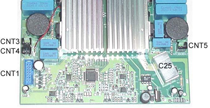
12 Possibility inductor size 1 medium 175mm medium 175mm 2 small 145mm medium 175mm 3 large 210mm small 145mm 4 (red arrows) 4.5 Power Module small 145mm with medium 175mm in common support plate General comments The power module can generate the power supply voltage, with the relative intensity and frequency, for the 2 relative inductors with a total maximum power of 3200W. The following inductor sizes can be combined together and be connected to a power module: bodies, placed symmetrically. The heat dissipater bodies are cooled by means of air, which comes through the air channel. All the functions in the power module are controlled by an ASIC, which has a serial connection with the microprocessor of the control module. The connection with the control module is made by means of a 14- thread strip tape wire. The power module is connected directly, through the filtering module, with the mains voltage Power module connections CNT 1 Tape cable to control module CNT 2 230V Output to control module (FSTN/L loop) CNT 3 Fan connection CNT 4 Connection for NTC Inductor 1 CNT 5 Connection for NTC Inductor 2 FSTN/L 230V input from filter module FST1/C Inductor 1 connection FST2/C Inductor 2 connection Possibility Inductor size 1 Inductor size 2 1 medium 175mm (1600W) medium 175mm (1600W) 2 small 145mm (1200W) medium 175mm (1600W) 3 large 210mm (2000W) small 145mm (1200W) 8 GBT and 2 double diodes are located, among others, in the power module, which are secured with rivets to 2 large heat dissipater r030061en a Seite 12 von 42


13 r030061en a Seite 13 von 42
14 4.5.3 Power module connection occupation to module control to control module Fan connection NTC Inductor 1 connection NTC Inductor 2 connection Inductor 1 connection inductor 2 connection from filtering module PIN CNT 1 CNT 2 CNT 3 CNT 4 CNT 5 FST1/C FST2/C FSTN/L 1 Ground Neutral + 24V Neutral V Phase 230V Fan CON. (Ground) Phase 230V 3 SEL 4 Data 5 Ground 6 NTC Inductor 1 7 NTC Inductor 2 8 Ground 9 NTC-Power module V 11 Clock 12 E 13 Fan CON. (Ground) This connection is directly joined to the adjacent FSTN/L connection. The mains voltage will be sent from here to the control module. At this point the power supply voltage of the fan can be measured. The fan will be controlled by connecting and disconnecting the ground. The fan activation temperature must be exceeded in the measurement. It can measure the resistance value of the NTC inductor in the connector removed. The resistance value is 10 kohms at 25 C. Here the high voltage is given with a frequency of KHz to supply the inductors. A measurement can be made with instruments from the customer technical service. Here it will measure the mains voltage coming from the filtering module. 14 Ground r030061en a Seite 14 von 42
15 4.6 Induction control module Control module connections General comments The most important components of the control module are a microprocessor, a power supply source with an output voltage of + 5V and + 24V continuous voltage, relay K21, connections CNT 1 to CNT 8 as well as the earth connection of the Touchcontrol FST 1. The designations of the connections are printed on the plate. The earth tapping of the control module is carried out through the stud bolt and the base plate Functions of the microprocessor The control adjustments will be exchanged by series (through a 5-pole cable) between the Touchcontrol or the Display module and the control module DISCONNECTION / CONNECTION Cooking adjustment positions or levels Boost function and also power module or control module information such as Pan detected YES / NO Boost CONNECTION / DISCONNECTION. The orders of the Touchcontrol or of the Display module will be processed through the microprocessor and transmitted through a 14- pole tape strip wire to the power modules. The microprocessor will also process information from the power module and from NTC probes and will send information back through the interface to the Touchcontrol or to the Display module. The appliance is controlled through parameters, which are saved in the EEPROM memory of the microprocessor. CNT 1 CNT 2 CNT 3 CNT 4 CNT 5 CNT 6 CNT 7 CNT 8 Tape cable to the power module on the right Tape cable to the power module on the left Serial connection with the Touchcontrol or the Display module Connection for special cooking field or plane controls (free) Connection for special cooking field or plane controls (free) Connection for special Display modules (free) or Connection for verification instrument V of the mains connection (loop through the left power module) 230V Output to Touchcontrol or to the Display module (loop through CNT7) The card connectors to CNT3 and CNT4 are not encoded so they can be plugged in or fitted mistakenly. With the connectors unplugged the cables must remain facing downward. r030061en a Seite 15 von 42
16 4.6.4 Control module connections occupation Power module on the right Power module on the left Touchcontrol or Display module (only Balay) (only Balay) Verifications instrument of the mains connection to the Touchcontrol PIN CNT 1 CNT 2 CNT 3 CNT 4 CNT 5 CNT 6 CNT 7 CNT 8 1 Ground Ground + Ub 12-18V A Phase 230V + 5V Neutral Neutral V + 24V Ground B Phase ATM V Phase 230V Phase 230V internal 3 SEL SEL RW series C Clock 4 Data Data Clock series D Ground 5 Ground Ground Data M4 SYNC 6 NTC-Inductor 1 NTC-Inductor 1 M3 Data 7 NTC-Inductor 2 NTC-Inductor 2 M2 + 24V 8 Ground Ground M1 Ground 9 NTC-Power module NTC-Power module V + 5V 11 Clock Clock 12 E E 13 Fan AN (Ground) Fan AN (Ground) 14 Ground Ground r030061en a Seite 16 von 42
 are found under these marks.")
17 4.7 TouchControl The cooking planes with TouchControl are sent by contact of the zones marked on the ceramic glass hub surface. The sensor "capacitive" keys (conductor rubbers) are found under these marks. Sensor keys from left to right: Main switch Child lock Boost switch for left inductors Plus / minus key for front left inductor Plus / minus key with intermediate timer key for back left inductor Plus / minus key for back right inductor Plus / minus key with intermediate timer key for front right inductor Boost switch for right inductors Selector switch for plate-warmer plate with CI (the figure shows Touchcontrol of CI without plate-warmer - conduction rubber and lighting module are missing) The cooking positions or levels and the times of the Timer function will be shown through 7 segment indications. The connection / disconnection state of the other functions will be shown by means of lighting modules with coupled masks. After connecting the mains voltage the Touchcontrol will be on "Standby" mode. Only the main switch will be ready to work and possibly the residual heat or an error message will be shown. The activation of the main switch will cause the release of the remaining sensor keys, so that all the functions can be adjusted. Simultaneously the interface or serial interconnection will be activated and a data exchange can be carried out between the Touchcontrol and the control module. The Touchcontrol is in "Active mode. 4.8 Universal type support element The power module, the filtering module, the cooling fan with the air channel and the inductors with NTC probes will be secured in or on the support element. The following inductor sizes can be combined together and mounted on the support element: Possibility Inductor size Inductor size 1 (Upper figure) round marks 2 (Central figure) round marks 3 (Lower figure) round marks 4 (Lower figure) red arrows medium 175mm small 145mm large 210mm medium 175mm medium 175mm small 145mm small 145mm con medium 175mm on common support plate r030061en a Seite 17 von 42
18 As the support element is a universal type part, it will be necessary to shorten different fastening pivots in the support element depending on the combination of inductors (see marks). When the assembly is carried out, this must begin with the inductor situated over the fan, as the NTC probe cable must pass under the other inductor. 4.9 Induction filtering modules Operation The filtering module is comprised of a combination of coils (L), capacitors (C) and resistors (R). The module is located between the mains connection (230V) and the power module. The filtering module permits the passage of the mains voltage without any impediment. Any interferences (anomalies), which might be generated in the appliance will be blocked with respect to the mains. In order it to work perfectly, filtering module must be correctly earthed. In the 60 and 80 cm wide appliances, the earth tapping is done through the base plate. In the 30 cm wide appliances the earth tapping is not done through the base plate, but through an additional earth tapping cable with AMP connection Verification see Verification of the induction filtering module r030061en a Seite 18 von 42
19 5 FUNCTIONS 5.1 Boost Function With the Boost function we can heat the product to be cooked much more quickly. To do this 150% of the maximum normal power will be made to reach the induction cooking zone. After reaching the desired cooking temperature the user should deactivate the Boost function. The Boost function is deactivated after 10 minutes at the latest. If certain limit temperatures are exceeded in the cooking plane or place, the Boost function will be disconnected before the maximum time of 10 minutes has elapsed. Each power module can simultaneously supply 2 inductors, whose sum of powers does not exceed 3,200 W. If only one inductor, connected to a power module, works, the Boost function may be activated so that the inductor receives the 150% of power. 5.2 Basic induction principles Overview The Boost function may be activated in principle in all the cooking zones. For this it will be necessary for the second cooking zone of the same power module not to be activated. Thus, then in a cooking plane with quadruple induction you may work simultaneously with a maximum of two cooking zones with high power Operation To activate it, firstly the highest adjustment level or position must be applied in the desired cooking zone. Then the Boost function will be connected by pressing the sensor switch on the Touchcontrol. The function may only be elected when the other cooking zones of the same power module are disconnected. if they are not disconnected the Boost indication will flash and it will not be activated. The use of induction heating in glass-ceramic cooking devices has existed since With this technique, the container is heated directly. Therefore the cooking surface heats up only as a result of the heat transmitted from the container to the glass, which is much lower than in conventional systems. The base of the container is heated by the electric currents that circulate in its base and which are induced by a variable, mediumfrequency magnetic field generated by the inductors located underneath the ceramic glass. Only containers with a base made of ferromagnetic steel or iron can be used with induction cooktops. Containers that cannot be used for induction can be recognised by the magnet test. Even though it is recommendable to use containers that fit the size of the cooking zone, containers of a smaller diameter can be used without causing notable reductions of efficiency. The cooktop control reduces the power delivered to small containers and, if applicable, stops supplying power when the container does not have the minimum required diameter. The power inverter transforms the 50 Hz of the power grid into an alternating current with a frequency between 20 and 50 Hz. Direct heating of the container base provides the induction system with very fast heating. Likewise, the system reacts very quickly to power level changes. r030061en a Seite 19 von 42
20 Induction provides very precise control of the power levels, wherefore it allows delicate recipes to be prepared. A temperature sensor under the glass is used in order to protect the inductor, and it moreover allows detecting that an empty container is being over-heated and stopping the heating process. 5.5 Timer Function In some of the induction appliances two cooking zones are equipped with a Timer function. After setting the desired cooking level or position, a cooking time that varies from 1 minute to 99 minutes may be selected by pressing the Timer sensor and then the plus key (priority time 10 minutes) or minus key (priority time 30 minutes). The last time that has been set will flash for 5 seconds on the Display, showing again the cooking level (speed) afterwards. The time remaining may be consulted by pressing the Timer sensor. The Cooking zone will disconnect after the time. 5.6 Pan detection 5.3 Induction power control 5.4 Temperature control (STC) All the induction cooking zones have an automatic pan or casserole presence detection. Appropriate pans and frying pans with a base diameter of > 80 cm will be detected. The power will automatically adapt to the pan diameter. If the presence of a pan is not detected after setting the cooking level (no pan has been placed or an unsuitable pan has been placed on it), the cooking position or level set will flash on the Display and no power will be generated. After 90 seconds an acoustic signal will be heard and the induction cooking zone will disconnect. If a pan is detected, the display will constantly show the cooking level set and power will be generated according to the cooking level set. r030061en a Seite 20 von 42
21 5.7 TouchCtrl and ExtCtrl Parameters with BO/SI/NE Cooking level 0 Cooking time in minutes (not all appliances) Conventiona l heating zone Induction heat. zone III ED in % Connectio n time seconds Disc. time in seconds Cycle period in seconds Service frequency Conventional heating zone Induction Service time limit in hours r030061en a Seite 21 von 42


22 5.8 Block Diagram Touch 60 cm r030061en a Seite 22 von 42
23 6 REPAIR 6.1 Induction III 60 cm wide Dismounting the appliance: Remove the cooking plate from the worktop. Leave the appliance with the ceramic glass hob facing down. Use an appropriate base to protect the ceramic glass hob. Remove the 7 setscrews from the base plate. Remove the earth tap screws from the filtering modules and from the control module (threaded screws, bear in mind the toothed washers). Afterwards the base plate can be removed Mounting the appliance: Mount the base plate. Slightly screw the earth tap screws of the control module and of the filtering modules in the first place (do not forget the toothed washers) and then the 7 setscrews of the base plate. Adjust the base plate and tighten all the screws equally. r030061en a Seite 23 von 42
24 7 FAULT DIAGNOSTICS 7.1 The cooking automatic does not work Description of the fault Cooking position Time in minutes The customer complains that the maximum cooking level or speed does not connect for sufficient time or connects for too long and that the switch over to the heat maintenance or continuation position takes place too early or too late Cause The automatic cooking system is a help tool that often awakes exaggerated expectations in the customer. Since electrical cookers appeared, in the majority of the cases the customer usually sets the highest level or position at the beginning and for a certain length of time in order to make the product boil as quickly as possible, then setting the temperature to a lower cooking position or a heat maintenance position. The automatic cooking system now takes on these steps, making the product heat quickly at the beginning and after a certain length of time returning to a lower position, chosen previously, or to the heat maintenance position Verification / repair Verify the cooking time of a cooking position (preferably in cooking position 1) Boost This is based on the hypothesis that the automatic cooking system of all the levels or positions works perfectly if the operation verified in one of them is correct. If the cycle times differ from the specifications established in the Table, the electronics must be replaced. r030061en a Seite 24 von 42
25 7.2 Voltage is detected in the pan or frying pan Description of the fault The customer notes a slight shock when he/she touches a pan or a frying pan working with induction Cause of the fault Induction cooking planes and zones use magnetic fields to heat the pans and frying pans. There is a capacitive coupling between the inductor (electromagnetic field generator under the ceramic glass hob) and the pan or frying pan. As a result, a small part of the voltage is transmitted from the inductor to the pan or frying pan Explanations It is true that the voltage in the pan or frying pan, measured with a voltmeter is around 80 V. This voltage induced in the pan or frying pan is reduced in agreement with the reduction of the impedance with respect to earth. If the pan or frying pan is touched with the hand, the voltage will be reduced to approx. 40 V. Induced voltage cannot, therefore, cause people any harm. Even though BSH induction appliances satisfy all the specifications, there may be sensitive people who notice the induced voltage with certain types of pan or frying pan handles. This will not imply any risk for the user. Bearing in mind the physical peculiarities the following explanation can be given: The technology of the BSH induction appliances is optimised with respect to the lowest possible voltage in pans and frying pans. BSH induction appliances satisfy all the national and international standards and provisions established in this regard. Under BSH worst case conditions, induction appliances show a leak current of 5.3 ma at the most. This is a value, which is more than seven times below the limit value permitted of 40 ma. This current is measured, according to standards, using a passive network. the network simulates the impedance of a human body. r030061en a Seite 25 von 42
26 7.3 Verification of the TouchControl YL90/93/ TC YL90 A verification of the TouchControl data transmission with the induction control module through the interface or series interconnection cannot be carried out with the customer technical service instruments TC YL93 The TouchControl will be tested by carrying out a practical verification of all the functions that may be used. Anyway, the serial interface service voltage can be measured when it is activated (TouchControl in "Active" mode). The TouchControl has an integrated verification program with which different parameters as well as optic and acoustic fault messages can be read TC YL98 r030061en a Seite 26 von 42
27 7.4 Fault indications - TouchControl YL90/93/98/ Acoustic messages of TouchControl YL90 Normal operation Qtty/Time Sequence Description Indication U400 F8 E F2 ErXY U400 is statically shown on the Display and a lasting acoustic signal is heard if the electronics connect at 40 V due to an erroneous connection of the hob. Immediately disconnect the hob from the mains. The indication will disappear when the fault is eliminated. F and 8 flash alternating with the relative indication of the cooking plane if the "service time limitation" has reacted. The "service time limitation" periods will depend on the cooking position set and vary between 1 and 10 hours. E flashes alternating with the cooking position or the residual heat indication on the relative Display in the event of "lasting activation" of a sensor (> 5 seconds) and a signal is heard for a certain time. In the case of lasting activation of the main switch E will flash on all the Displays. A lasting activation may occur, for example due to leaving objects or liquid spilling over in the sensor area. The indication will disappear when the cause is eliminated and any key is pressed. F and 2 will flash alternating with the relative indication of the cooking zone when the "own temperature of the TouchControl" is excessive (>100 C). the electronic have detected an "internal fault" and must be replaced (except with Er32). Main switch activated 1x beep Plus key pressed 1x beep Minus key pressed 1x beep Area connector pressed 1x beep Repeat function in operation whilst activated beep Trip time elapsed 1x beep Erroneous operation The disconnection has been activated due to excessive temperature Key time exceeded (after 5 seconds permanently pressed) Erroneous connection (400V instead of 230V) The operation time limitation has reacted. 1x variable 1x beep Permanent sound beep The key "acknowledgement of receipt" through the buzzer" may be connected and disconnected by the customer. The anomalous operation acoustic signals remain activated. r030061en a Seite 27 von 42
28 7.6 Acoustic messages of TouchControl YL Acoustic messages of TouchControl YL98 Normal operation Qtty/Time Main switch activated 1x Sequence beep Plus key pressed 1x beep Minus key pressed 1x beep Area connector 1x beep pressed Timer key pressed 1x beep Repeat function in operation whilst activated beep Trip time elapsed 1x beep Erroneous operation Disconnection activated due to excessive temperature Key time exceeded (after 5 seconds permanently pressed) 1x variable beep Erroneous connection (400V instead of Permanent sound 230V) The operation time 1x limitation has reacted. Timer time ended 1x beep Description The key "acknowledgement of receipt" through the buzzer" may be connected and disconnected by the customer. The anomalous operation acoustic signals remain activated. beep Normal operation Qtty/Time Sequence Description Main switch activated 1x Option: no signal tone Plus key pressed 1x Option: no signal tone Minus key pressed 1x Option: no signal tone Area connection key pressed Cooking pulse key pressed 1x 1x Option: no signal tone Option: no signal tone Timer key pressed 1x Option: no signal tone Repeat function activated Trip time ended 1x Timer ended 2 minutes 2 short tones in one second / 1 disconn. sec. Incorrect operation Key time exceeded (after 5 sec. permanently pressed Error message F2 (excessive temperature) Operation time limitation F8 Erroneous connection (400 V instead of 230V) 10 seconds 1x 1x 1 sec. conn. / 1 sec. disconn. 1 sec. conn. / 1 sec. disconn. Lasting signal r030061en a Seite 28 von 42
29 7.8 Activate customer service control program YL90/93 Step Action and indication 0 The appliance is disconnected. 1 Press the minus key of cooking plane 3 and keep it pressed. 2 Connect the main switch and keep it connected. 3 Each one of the segments of the 7-segment indications will light up briefly. 4 Once the segments have lit up, briefly release the minus key of cooking plane 3 (within 1 second). 5 After another second each one of the segments of the 7-segment indications will light up briefly again. 6 Press the minus key again of cooking plane 3 (within 1 second). 7 "P and "7" will flash on the four heating zone indications at intervals of one second. The customer service mode will be activated. The customer service mode will be exited automatically after 30 seconds if no input is made or if the last point of the menu has ended. r030061en a Seite 29 von 42
30 7.9 Activate customer service control program YL98 Step Action and indication 0 The appliance is disconnected. 1 Press the plus key and keep it pressed. 2 Connect the main switch and keep it connected. 3 Each one of the segments of the 7-segment indications will light up briefly. 4 Once the segments have lit up, briefly release the plus key 3 (within 1 second). 5 After another second each one of the segments of the 7-segment indications will light up briefly again. 6 Press the plus key again (within 1 second). 7 "P and "7" will flash on the four heating zone indications at intervals of one second. The customer service mode will be activated. 8 The customer service mode will be exited automatically after 30 seconds if no input is made or if the last point of the menu has ended. r030061en a Seite 30 von 42
31 7.10 Customer service control program YL90 Action Indication State 7 The appliance is in customer service mode "P" and "7" flash alternately in the 4 heating zone indicat. at sec. intervals The parameters can be read. 7.1 Minus key of heating zone 1 e.g. " " The Software version will be shown 7.2 Plus key of heating zone 1 e.g. " " 7.3 Minus key of heating zone 2 e.g. " " The erroneous connections of the electronics will be shown (400 V) The maximum temperature reached in YL90 will be shown; the binary value of 215 corresponds to 100º C 7.4 Plus key of heating zone 2 e.g. " " The operation hours will be shown 7.5 Minus key of heating zone 2 e.g The control part number will be shown 8 Main switch "P" and "8" flash alternately in the 4 heating zone indicat. at sec. intervals Permanent operation conn. / disconn. 8.1 Plus key of heating zone 1 " " Operation time limitation bridged 8.2 Minus key of heating zone 1 " " Operation time limitation activated again 9 Main switch "P" and "9" flash alternately with the 4 heating zone indicat. at sec. intervals 9.1 No key must be pressed for 2 seconds. - will appear in all indications. 9.2 All the sensor keys in any order (including the main switch) 0 : in order; 1 : not sensitive enough; 2 : too sensitive; 9 : several keys of a cooking plane pressed at the same time Sensor key test The tolerance limits are closer in the sensor key test than necessary for normal operation. A passed test guarantees therefore the exact operation in normal service. The standby values in non-activated state are measured. Once all the keys have passed the test all the LED's + buzzer + cooking plane 1 relays (including main switch) will be activated. Then the program will be exited with a Reset. r030061en a Seite 31 von 42
32 7.11 Customer service control program YL93 Pulsation Indication State 7.0 The appliance is in customer service mode "P" and "7" flash alternately in the 4 heating zone indicat. at sec. intervals The parameters can be read. 7.1 Minus key of cooking plane 1 e.g. " " *) The Software version will be shown. 7.2 Plus key of cooking plane 1 e.g. " " *) 7.3 Minus key of cooking plane 2 e.g. " " *) The erroneous connections of the electronics will be shown (400 V) The maximum temperature reached in YL90TE will be shown; the binary value of 215 corresponds to 100 ºC 7.4 Plus key of cooking plane 2 e.g. " "*) The operation times will be shown 7.5 Minus key of cooking plane 3 e.g *) The control part number will be shown 8.0 Main switch "P" and "8" flash alternately with the 4 heating zone indicat. at sec. intervals Permanent operation connection / disconnection 8.1 Plus key " " Operation time limitation bridged. 8.2 Minus key " " Operation time limitation activated again. r030061en a Seite 32 von 42
33 7.12 Customer service control program YL98 Pulsation Indication State 7.0 The appliance is in customer service mode "P" and "7" flash alternately in the 4 heating zone indicat. at sec. intervals The parameters can be read 7.1 Key to connect areas e.g. " " The Software version will be shown 7.2 Select key of cooking zone 1 e.g. " " 7.3 Select key of cooking zone 2 e.g. " " The erroneous connections of the electronics will be shown (400 V) The maximum temperature reached in YL9TE will be shown; the binary value of 215 corresponds to 100 ºC 7.4 Minus key e.g. " " The operation times will be shown 7.5 Plus key e.g Control part number will be shown 8.0 Main switch "P" and "8" flash alternately in the 4 heating zone indicat. at sec. intervals Permanent operation connection / disconnection 8.1 Plus key " " Operation time limitation bridged 8.2 Minus key " " Operation time limitation activated again 7 Activate main switch "P" and "7" flash alternately with the 4 heating zone indicat. at sec. intervals Cycle starts again. r030061en a Seite 33 von 42
34 7.13 Verification of the NTC probes NTC probe in the inductor The temperature of each inductor will be watched with an NTC probe. The NTC probes of the inductors can be replaced individually. When mounting a new NTC probe thermoconductor putty must be used NTC probe in heat dissipaters of the power module T in (ºC) R in Ohms T in (ºC) R in Ohms 10 19, , , , , ,779 The temperature of the power module will be watched with an NTC probe, which will be secured with rivets to the body of the heat dissipater of the power module. This NTC probe cannot be replaced NTC probe of the induction control module The actual temperature of the induction control module is watched over with an NTC probe mounted directly on the flange. This NTC probe cannot be replaced or measured with customer service means Diagram and table of NTC probe values , ,410 16, ,059 15, ,725 14, ,406 14, ,101 13, ,811 13, ,535 12, ,271 11, ,019 11, ,779 10, ,549 10, ,330 10,000 r030061en a Seite 34 von 42
35 7.14 Verification of the induction filtering module Operation The filtering module is comprised of a combination of coils (L), capacitors (C) and resistors (R). The module is located between the mains connection (230V) and the power module. The filtering module permits the passage of the mains voltage without any impediment. Any interferences (anomalies) that may be generated in the appliance will be blocked with respect to the mains. For it to work perfectly the filtering module must be correctly connected to earth. In the 60 and 80 cm wide appliances, the earth connection is made through the base plate. In the 30 cm wide appliances the earth connection is not made through the base plate, but through an additional earth tap cable with AMP connection Verification At the input (in the figure on the left) and output (in the figure on the right) of the filtering module, measures 230V~. If there is no voltage (230V~) at the filter input, check connection to mains. If there is no voltage (230V~) at the filter output, replace the filtering module. r030061en a Seite 35 von 42
36 7.15 Verification of the inductor Firstly check the fuse mounted in the power module. If the fuse is faulty the whole power module must be The verification of the inductor will be made without voltage. changed. It is not possible to replace the fuse. Remove the inductor and carry out a visual inspection. Pay Measure the resistance between C24 and C25. If the special attention to the presence of areas with burns or to resistance is <10 kohms, the whole power module must be faulty connection cables. replaced. From an electrical viewpoint, the inductor consists of a copper coil with a really large conductor section. Verify if the coil makes contact to ground or if it is interrupted Verification of the cooling fan The fan is comprised of a rotor with a motor mounted on the inside. From a mechanical viewpoint verify if the fan is blocked or works in a forced way. The service or operation voltage is 24V =. The fan can be verified by applying an appropriate continuous voltage. The fan cannot be verified by measuring the resistor (protection diodes at the input). Measure the resistance between the two heat dissipater bodies. If the resistance is <10 kohms the whole power module must be replaced. Measure the resistance of the coil of the K3 relay. You will find the measuring points above diode D6. If the resistance were <1 kohms or >1.5 kohms the whole power module must be replaced. If no defect is noticed after carrying out all the verifications, but however no power is generated, change the power module Verification of the power module The power module will be verified without voltage. Remove the power module and carry out a visual inspection. Pay special attention to the presence of areas with burns or damaged components. r030061en a Seite 36 von 42

37 7.18 Verification of the induction control module The verification of the control module will be carried out with voltage (observe safety standards!). Set any of the cooking zones to position 1. The interface or serial interconnection of the TouchControl will now be activated and the service voltage will now reach relay K1 through connector CNT3 of the control module. You may measure this voltage in diode D6 (see mark on figure), which is connected in parallel with the input of the relay (12-18V=). The relay must enter and the 230V mains voltage will connect to a changeover power supply. Here continuous voltages of 24V and 5V will then be generated to supply the electronics. These voltages can be measured in the different connections of the control module (see Table given below). r030061en a Seite 37 von 42
38 Occupation of the control module connections Right module power Left module power Touchcontrol Verification instrument of mains connection to Touchcontrol PIN CNT 1 CNT 2 CNT 3 CNT 4 CNT 5 CNT 6 CNT 7 CNT 8 1 Ground Ground + Ub 12-18V A Phase 230V + 5V Neutral Neutral V + 24V Ground B Phase intern. ATM V Phase 230V Phase 230V 3 SEL 4 Data 5 Ground SEL RW series C Clock Data Clock series D Ground Ground Data M4 SYNC 6 NTC-Inductor 1 NTC- Inductor 1 7 NTC- Inductor 2 NTC- Inductor 2 M3 M2 Data + 24V 8 Ground 9 NTC-Power module Ground M1 Ground NTC-Power module V + 5V 11 Clock 12 E 13 Fan CON. (Ground) 14 Ground Clock E Fan (Ground) Ground CON. r030061en a Seite 38 von 42
39 7.19 Quadruple induction verification instrument with TouchCtrl The fault messages will be shown flashing on the verification instrument ; the cooking positions set will be shown with constant light. Connect display to CNT6 of the induction control module. H = Overheating of an individual induction cooking zone (cooking zone NTC resistance < 8 ohms) Let the cooking zone cool down. Disconnect and connect again. Review habits of use and assembly of cabinet. Place 4 suitable pans. Set all the cooking zones in position 2. No erroneous function has been detected; the cooking levels from 1 to 9 will be reduced to an indication field of 1 to 6 on an outside Display; level 2 will be indicated as 1. The induction control module does not recognise the control signals of the TouchControl. Everything is in order. Verify the connection between TouchControl and induction control module to CNT3. Connect to CNT3 test mode in rotated position; if this is not successful, change the induction control module. hh = Overheating of a power module (heat dissipater NTC resistance < 420 Ohms) Let the cooking zone cool down. Disconnect and connect again. Review habits of use and assembly of cabinet r030061en a Seite 39 von 42


 Measure")

 and")
40 UU = Blocked / forced LEFT / RIGHT fan; fan connection interrupted (The indication is only shown during the operation of the cooker with the fan activated. Immediate indication is possible bridging an inductor NTC). Mechanically verify / replace. Measure if 24V are given in the fan connection. If not, change the induction control module. If there are, change the fan. P = Fault of the NTC probe of an induction cooking zone (Resistance < 1 Ohm or > 40 kohms) Measure resistance of the NTC probe: approx. 10 kohms at room temperature; if this is not the case, replace NTC probe. PP = The signals of the two cooking zone NTCs of the RIGHT / LEFT power module do not reach the induction control module Connection between induction control module (CNT1/CNT2 connection) and power module rusty / loose. bb = Fault of the NTC probe of the heat dissipater of the LEFT / RIGHT power module. (Resistance < 400 Ohms or > 40 kohms) Replace in accordance with power module. r030061en a Seite 40 von 42


41 Memory fault in the induction control module Replace induction control module EE = Hardware fault in the LEFT / RIGHT power module Replace the relative power module EEEE = Hardware fault of power modules or Hardware fault of control module AAAA = Overheating of the induction control module Disconnect a power module. If the fault message disappears: replace this power module. If not, connect it again and disconnect the other module. if the fault message remains, replace the induction control module If this occurs even with cold cooking zone, replace the induction control module. Review habits of use and assembly of cabinet as well as oven mounted below ONE SINGLE COOKING ZONE INDICATION FLASHES: induction cooking zone or its connection faulty; power transistor faulty; does not recognise presence of pan. Visual control of the induction cooking zone, possibly replace it. Replace power module. PPPP =The induction control module no longer recognises the cooking zone NTCs. Replace the induction control module UUUU = Fan surveillance faulty Replace induction control module COOKING LEVEL INDICATIONS FLASH IN PAIRS: transistor(s), etc. faulty, does not recognise presence of pan Replace control module. r030061en a Seite 41 von 42
1 SAFETY Touch Control YL161 ( Twist Pad) INSTALLATION FUNCTIONS OPERATION COMPONENTS REPAIR...
 INSTALLATION FUNCTIONS OPERATION COMPONENTS REPAIR...") REPAIR INSTRUCTI IONS I Ind IV:4I 1 SAFETY...3 4.15 Touch Control YL161 ( Twist Pad)...38 1.1 Safety observations... 4 1.2 Repair observations... 4 2 INSTALLATION...5 2.1 Assembly instructions... 6 3 OPERATION...9
REPAIR INSTRUCTI IONS I Ind IV:4I 1 SAFETY...3 4.15 Touch Control YL161 ( Twist Pad)...38 1.1 Safety observations... 4 1.2 Repair observations... 4 2 INSTALLATION...5 2.1 Assembly instructions... 6 3 OPERATION...9
TEIS Induction Module. 4 cooking zones hob with TAP user interface
 TEIS Induction Module 4 cooking zones hob with TAP user interface Introduction New development of a 3 zones or 4 zones Induction hob (for 3 zones the 140mm zone is not used) TEIS induction module = The
Operating and maintenance instructions for hobs
 EN Operating and maintenance instructions for hobs DHTCI30, UBIND60W Fig.1 Fig.2 Fig.3 Fig.4 Fig.5 min.5mm min.15mm Cajón Armario Horno Drawer Cabinet min.5mm min.15mm min.50mm Rmax.2mm D -1 +3 C-1 +3
Indesit Company. Multiplo 2008 Jaeger Platform. Fabriano, May 2008
 Indesit Company Multiplo 2008 Jaeger Platform Fabriano, May 2008 1 Legend Multiplo F Flush Product name Multiplo SF Semi-flush 2 Interfaces REAR WELL FRONT WELL PROGRAMMED COOKING ZONE REAR COOKING ZONE
IMPORTANT SAFETY INFORMATION
 319252GB.fm Page 11 Wednesday, September 3, 28 4:5 PM IMPORTANT SAFETY INFORMATION This manual contains important information regarding safety, the use and maintenance of your new hob. Read the manual
SERVICE MANUAL COOKERS
 SERVICE MANUAL COOKERS Electrolux Distriparts Muggenhofer Straße 135 D-90429 Nürnberg Germany Publ.-Nr.: 599 713 194 685 EN Built-in hob Induction TIGER/CHEETAH Fax +49 (0)911 323 1022 DGS-TDS-N Edition:
Refrigerator KE T
 Refrigerator KE 680-1-3T Service Manual: H8-74-07 Responsible: U. Laarmann KÜPPERSBUSCH HAUSGERÄTE AG E-mail: uwe.laarmann@kueppersbusch.de Tel.: (0209) 401-732 Customer Service Fax: (0209) 401-743 Postfach
MIXED INDUCTION / HI-LIGHT VITROCERAMIC HOB MH-F3BS
 MIXED INDUCTION / HI-LIGHT VITROCERAMIC HOB MH-F3BS User Instructions C Fig.1 F D1 G E C D C B A 2 30 mm 40 mm Fig.2 510 mm 580 mm 52 mm 50 Min 548 mm 560 mm 478 mm Min 490 mm 50 50 Min 3 3 2 2 1 1 Fig.3
TRUE INDUCTION DOUBLE BURNER MINI DUO COOKTOP MANUAL
 TRUE INDUCTION DOUBLE BURNER MINI DUO COOKTOP MANUAL DOUBLE BURNER MINI DUO INDUCTION COOKTOP MANUAL 1 TABLE OF CONTENTS I. II. III. IV. V. VI. VII. VIII. Control Panel Overview Cooktop Installation Important
ELECTRIC INDUCTION HOBS
 INSTALLATION AND OPERATION MANUAL ELECTRIC INDUCTION HOBS (BUILT-IN) Model: EH-DIH890 Please read the instruction manual carefully before using 1 TABLE OF CONTENTS PREFACE 1. SAFETY INSTRUCTION.. 2. INSTALLATION
IH 025 VOLCANO. Portable Induction Heater. smart mounting
 Portable Induction Heater IH 025 VOLCANO Bedienungsanleitung Instructions for use Mode d emploi Manuale d istruzioni Manual de usuario 2 Portables Induktions-Anwärmgerät IH 025 VOLCANO simatec ag Table
The Gaggenau Models and Dimensions. Edition 2013 / 2014.
 The Gaggenau Models and Dimensions. Edition 2013 / 2014. Cooktops. Gas cooktops. 94 Induction cooktops. 95 Planing notes for Induction cooktops. 98 Technical specifications. 99 93 200 series gas cooktop
GUIDE TO INSTALLATION AND USE. Cooking hob
 EN GUIDE TO INSTALLATION AND USE Cooking hob Dear Customer, Thank you for choosing a BRANDT cooking hob. We have put all our dedication and know-how into this appliance so that it can meet your needs.
REPAIR INSTRUCTIONS. TUMBLE DRYER Vented WTA34.. / WTA35..
 REPAIR INSTRUCTIONS TUMLE DRYER Vented WTA34.. / WTA35.. I. SAFETY INFORMATION Page 1 II. OPERATION Page 1 III. DESCRIPTION OF FUNCTION / TECHNICAL INFORMATION Page 2 IV. CONSUMPTION RATES / ENERGY REQUIREMENT
EDI604NF EDI704NF EDI905NF
 Instructions for use and installation Induction cooktop 17 EDI604NF EDI704NF EDI905NF 1 The Manufacturer strives for continuous improvements. For this reason, the text and illustrations in this book are
Installation, Operating and Maintenance Manual
 STATUS ZONES CONTROLS FIRE FAULT DISABLED FIRE 1 2 3 4 5 6 7 8 TEST FAULT DISABLED 1 5 BUZZER SILENCE RESET 1 2 TEST 2 6 LAMP TEST 3 SUPPLY 3 7 SYSTEM FAULT 4 8 SOUNDERS ACTIVATE/ SILENCE 4 FAULTS INSTRUCTIONS
SERVICE MANUAL REFRIGERATION
 SERVICE MANUAL REFRIGERATION ELECTROLUX HOME PRODUCTS S.p.A. Publication no. Spares Operations Italy 599 37 75-07 Corso Lino Zanussi, 30 060824 I - 33080 PORCIA / PN (ITALY) ITZ/SERVICE/AA Fax +39 0434
INSTALLATION INSTRUCTIONS AND RECOMMENDATIONS FOR USING AND MAINTAINING INDUCTION AND CERAMIC HOT PLATES TOUCH CONTROL
 INSTALLATION INSTRUCTIONS AND RECOMMENDATIONS FOR USING AND MAINTAINING INDUCTION AND CERAMIC HOT PLATES TOUCH CONTROL 2 Presentation 3 4 Installation Minimum distances TEKA Oven Units in mm. 5 Safety
2 INSTALLATION OPERATION FUNCTIONS SAFETY Compressor Compartment... 10
 REPAIR INSTTRUCTTI I ION REFFRI IGERATTOR 1 SAFETY... 3 4.1 Compressor Compartment... 10 2 INSTALLATION... 4 4.2 Fridge Evaporator Compartment... 11 4.3 Freezer Evaporator Compartment... 12 3 OPERATION...
BIC603T BIC604T BIC75T
 Instructions for the Use and Care and Installation of BIC603T BIC604T BIC75T Induction Cooktop Dear Customer You will find that the modern look of your Blanco rangehood blends in perfectly with your kitchen
Induction Generation 8 G8
 Induction Generation 8 G8 Whirlpool Europe Service Competence Center Office +49-(0)711 810 71-3567 Mobile +49-(0)711 810 71-83567 Pasquale Lattuca pasquale._lattuca@whirlpool.com Service Expert Cooking
MIXED HOB MH-F3B. User Instructions. induction. hi-light. induction
 hi-light induction induction MIXED HOB MH-F3B User Instructions C Fig. 1 F G E A1 A B C D Fig. 2 Fig. 3 50 mm ~ 2 mm 20 mm min. 50 mm Fig. 5 NO YES 2 50 mm 30 mm 40 mm Fig. 4 350 mm 900 mm 510 mm 50 mm
TECHNICAL INFORMATION Touchtronic Clothes Dryers
 TECHNICAL INFORMATION Touchtronic Clothes Dryers Includes: T1302, T1303, T1322, T1329ci T1403 & T1405 2004 Miele This page intentionally left blank. Table of Contents GENERAL INFORMATION A. Warning and
Instruction manual for downdraft hood
 Instruction manual for downdraft hood Model code: BODY / DD600BK - BODY / DD900BK BODY / DD600SS - BODY / DD900SS Contact Caple on 0844 800 3830 or for spare parts www.4caple.co.uk The symbol on the product
BACE cm ceramic electric cooktop GECE cm ceramic electric cooktop
 BACE9004 90cm ceramic electric cooktop GECE9004 90cm ceramic electric cooktop 1 BHI609 60cm Front touch control induction zone hob 2 User Manual for your BACE9004 GECE9004 90 cm Front touch control 4 radiant
GLASS CERAMIC INDUCTION COOKTOP
 PHD 614 C GLASS CERAMIC INDUCTION COOKTOP USER'S MANUAL Dear customer, Thank you for buying a PHILCO brand product. So that your appliance serves you well, please read all the instructions in this user's
with control panel Hobs + Hobs The A Z of Gaggenau hobs and hobs with control panels
 29 The A Z of Gaggenau hobs and hobs with control panels Appliance depth 4 cm A not insignificant factor in kitchen design, the minimal depth of many Gaggenau hobs saves space and simplifies installation
Built-in ceramic-glass cooktop
 Built-in ceramic-glass cooktop The built-in ceramic-glass cooktop is manufactured for household use only. Our appliances are packed in environmentally friendly materials which may be recycled, deposited
on the use of the device and understand the dangers its use involves. User cleaning and maintenance may not be done by unsupervised
 Safety warnings: If the ceramic glass breaks or cracks, immediately unplug the stovetop to avoid electric shocks. This appliance is not designed to work with an external timer (not built into the appliance)
60cm Built In Induction Cooktop
 20100618 issue 2 啊哈 60cm Built In Induction Cooktop Installation and User manual Content Safety instructions---------------------------------- 1 Product description--------------------------------- 3 Installation---------------------------------------------
SERVICE MANUAL REFRIGERATION
 SERVICE MANUAL REFRIGERATION Electrolux Home Products S.p.A. Spares Operations Italy Corso lino Zanussi, 30 I - 33080 Porcia (PN) Fax +39 0434 394096 S.O.I. Edition: 10.2006 Publication no. 599 38 38-50
INSTRUCTIONS FOR USE
 -1- INSTRUCTIONS FOR USE INDUCTION COOKERS Base-Line Fajita Heater SH/BA 3500 FH -2- CONTENT 1 General remarks...3 1.1 Description of danger signs...3 1.2 Purpose of induction cookers...4 2 Description
HR 601 C A AUS. ENGLISH Instructions for use Page 2
 HR 61 C A AUS ENGLISH Instructions for use Page 2 1 INSTRUCTION FOR USE IMPORTANT SAFETY INSTRUCTIONS BEFORE USING THE GLASS CERAMIC HOB INSTALLATION ELECTRICAL CONNECTIONS ENERGY SAVING TIPS SAFEGUARDING
User Manual Watt Drop-In Induction Range. Model: DC /2017. Please read and keep these instructions. Indoor use only.
 1800 Watt Drop-In Induction Range Model: DC1800 08/2017 Please read and keep these instructions. Indoor use only. www.avantcoequipment.com 1 Specifications Model No... DC1800 Power Rating... 500-1800W
1 SAFETY FUNCTIONS INSTALLATION OPERATION COMPONENTS REPAIR FAULT DIAGNOSTICS...56
 1 SAFETY... 3 1.1 Safety observations... 3 1.2 Repair observations... 3 2 INSTALLATION... 4 2.1 Assembly instructions... 4 3 OPERATION... 7 3.1 Induction cookware... 7 3.2 Modification of the YL146/147/...
1 SAFETY INSTRUCTIONS FUNCTIONS...39
 INSTTRUCCI I IONES DE REPARACIÓN Ind IV Ad:5I 90 cm 1 SAFETY INSTRUCTIONS... 2 5 FUNCTIONS...39 1.1 Safety instructions... 2 5.1 Basic principles of induction... 39 1.2 Repair instructions... 2 5.2 Regulation
MAKING MODERN LIVING POSSIBLE INT INT EFIT 550. User Guide and Installation Manual. Danfoss Heating
 MAKING MODERN LIVING POSSIBLE EFIT 550 User Guide and Installation Manual Danfoss Heating Thank you for buying a Danfoss product. With this purchase you have obtained a product of the highest quality,
Built-in Electric Ceramic Hob
 Instruction Manual Built-in Electric Ceramic Hob LCHOBTC14 Image for indication only. GB Contents Safety Warnings... 3 Unpacking... 5 Product Overview... 6 Top View...6 Control Panel...6 Before Using Your
LINEAR HEAT DETECTION CABLE DURÁN-SAFE
 LINEAR HEAT DETECTION CABLE DURÁN-SAFE Installation & User Manual 2018 DURAN ELECTRONICA S.L. - All rights reserved www.duranelectronica.com I-manSAFECABLE-v05 TABLE OF CONTENTS Pages 1. INTRODUCTION...
600mm INDUCTION Cooktop
 PRODUCT SERVICE NUMBER 1800 805 300 600mm INDUCTION Cooktop MODEL: ICI6GE2 RSDMC1208 InstallatIon and operation Manual Dear customer: Thank you for purchasing the the induction hotplate our product can
PNC 1000 SERIES 2, 4, 8 Zone Fire Alarm Control Panel
 PNC 1000 SERIES 2, 4, 8 Zone Fire Alarm Control Panel INSTALLATION, OPERATION AND MAINTENANCE MANUAL Version: CN-PM-1000.VER1.1-12/2012 EN54 INFORMATION In accordance with EN 54-2 clause 13.7, the maximum
Table de cuisson Cooking Hob Placa de cocción Placa de cozinha Kochfeld
 FR EN ES PT DE GUIDE D INSTALLATION ET D UTILISATION GUIDE TO INSTALLATION AND USE MANUAL DE INSTALACIÓN Y UTILIZACIÓN MANUAL DE INSTALAÇÃO E DE UTILIZAÇÃO EINBAU- UND BETRIEBSANLEITUNG Table de cuisson
Service Information. WNes 2956 appliance documentation. Service Information no. 27/2004 LHG/TKD-Fe/June SI
 After Sales Service International Service Information Service Information no. 27/2004 LHG/TKD-Fe/June 2004 WNes 2956 appliance documentation Page 1/26 Contents 2.0. Extract from Operating Instructions
TECHNICAL INFORMATION T1500 Series Clothes Dryers
 TECHNICAL INFORMATION T1500 Series Clothes Dryers 2003 Miele - Table of Contents 1.0 CONSTRUCTION & DESIGN 1.1 Appliance Overview - Vented 1 1.2 Appliance Overview Condenser Models 2 1.3 Controls Overview
Service: to SLK Laboratory Hot Plates glass made of ideas
 SLKServiceV04eng.doc 17 Version: 04.07.2002 Contents Page Contents... 18 1 Safety information... 20 2 Introduction... 21 2.1 Required tools...21 2.2 Required measuring and testing means...21 2.3 Setting
User Manual Watt Drop-In Induction Range. Model: ID18DB 08/2017. Please read and keep these instructions. Indoor use only.
 3100 Watt Drop-In Induction Range Model: ID18DB 08/2017 Please read and keep these instructions. Indoor use only. www.avantcoequipment.com 1 Specifications Model No... ID18DB Power Rating... Front: 500-1300W,
Products documentation (REVISION DATE: 03/10/2011) OMFP6010 (60cm PIROLITIC OVEN)
 OMFP6010 (60cm PIROLITIC OVEN)") Products documentation (REVISION DATE: 03/10/2011) OMFP6010 (60cm PIROLITIC OVEN) Ovens Service Manual Models OMFP6010 CONTENTS This document has been published to be used for service only. The contents
Products documentation (REVISION DATE: 03/10/2011) OMFP6010 (60cm PIROLITIC OVEN) Ovens Service Manual Models OMFP6010 CONTENTS This document has been published to be used for service only. The contents
Micro-Computer Induction Cooktop SR-1885SS
 Micro-Computer Induction Cooktop SR-1885SS INSTRUCTION MANUAL Thank you for your purchase. Please read thoroughly before initial use and keep in a safe place for future reference. INDEX Important safeguards....
INDUCTION COOKER User Guide
 EN INDUCTION COOKER User Guide www.tefal.com C A D B L E M N F G H I J K IMPORTANT SAFETY INSTRUCTIONS Read these instructions for use carefully before using your appliance for the first time and keep
INDUCTION COOKER MODEL: EIC-G1810(BK) Owner s Manual. Please read this manual carefully before operating your set. Retain it for future reference.
 Owner s Manual. Please read this manual carefully before operating your set. Retain it for future reference.") INDUCTION COOKER MODEL: EIC-G1810(BK) Owner s Manual Please read this manual carefully before operating your set. Retain it for future reference. Record model number and serial number of the set. See the
INDUCTION COOKER MODEL: EIC-G1810(BK) Owner s Manual Please read this manual carefully before operating your set. Retain it for future reference. Record model number and serial number of the set. See the
Warning: 230V / 1ph / 50Hz V / 3ph / 50Hz. Remarks: Make sure that you have enough power. (See page 15 Cable table)
") 1 2 Warning: - Do not place your hand or any other objects into the air outlet and fan. It could damage the heat pump and cause injuries; - In case of any abnormality with the heat pump, cut off the power
1 2 Warning: - Do not place your hand or any other objects into the air outlet and fan. It could damage the heat pump and cause injuries; - In case of any abnormality with the heat pump, cut off the power
Instructions 1 This appliance is intended for non-professional use within the home. 2 Before using the appliance, carefully read the
 Instructions This appliance is intended for non-professional use within the home. 2 Before using the appliance, carefully read the instructions contained in this manual, as they provide important information
Induction Cooktop User's manual
 Induction Cooktop User's manual EN Prior to using this appliance, please read the user's manual thoroughly, even in cases, when one has already familiarised themselves with previous use of similar types
BIC603S BIC604S BIC75S
 Instructions for the Use and Care and Installation of BIC603S BIC604S BIC75S Induction Cooktop Dear Customer, Thank you for buying a BLANCO cooktop. Before we continue telling you about this cooktop, we
Essentia Project Artica Platform No Frost 60 cm Appliances 2011
 Essentia Project Artica Platform No Frost 60 cm Appliances 2011 Event Ca Maiano, May 2011 Presenter Piotr Kelm Francesco Nieli 0 Legend and User Interface Legend THR3 Interface (SQG_CL_32) MID Indesit
Focus 4010\ Focus 4010 HT porcelain firing furnace
 INSTRUCTION MANUAL Focus 4010\ Focus 4010 HT porcelain firing furnace Warning You have available one of the most precise dental furnaces equipped with a heating muffle made by the original manufacturer
TERMO-Blok TERMO-Extra TERMO-Blok PTV
 ELECTRIC BOILERS FOR CENTRAL HEATING TERMO-Blok TERMO-Extra TERMO-Blok PTV Contents 1. Introduction... 1 1.1. Applicable documents... 1 1.2. Retention of documents... 1 1.3. Introduction... 1 1.4. Heating
Induction Hob 2 YEAR GUARANTEE
 Induction Hob 2 YEAR GUARANTEE Model No. SDA-IH102BK-3GB THIS APPLIANCE IS FOR DOMESTIC USE ONLY READ ALL INSTRUCTIONS BEFORE USE. SAVE THESE INSTRUCTIONS FOR FUTURE REFERENCE. IMPORTANT SAFEGUARDS WHEN
GSWTM USER'S MANUAL CU-22A INDUCTION RANGE
 GSWTM USER'S MANUAL CU-22A INDUCTION RANGE 1 USE AND CARE INSTRUCTIONS IMPORTANT SAFEGUARDS READ ALL INSTRUCTIONS BEFORE OPERATION 1. Use an individual 208VOLT, 15 AMPERE electrical socket. 2. DO NOT block
DOUBLE BURNER COUNTER INSET. User Guide
 DOUBLE BURNER COUNTER INSET User Guide Table of Contents I. Cooktop Installation 1-3 II. Important Safety Information 4 III. Product Specifications 5 IV. How to Use 5 Power Invariance Technology 5 Using
Service Instructions
 BASIC EXCELLENT PERFECT U Universal ovens I Incubators S Sterilisers Service Instructions Mo Tu We Th Fr Sa Su t3 on off h t2 t1 t4 loop 4 3 2 1 STERI DEFRO C MIN MAX C IN 1 IN 2 OUT IN 1 IN 2 OUT % rh
Table of Contents 1. OVERVIEW SYSTEM LAYOUT SPECIFICATIONS FUNCTION... 11
 Table of Contents 1. OVERVIEW... 3 2. SYSTEM LAYOUT... 4 3. SPECIFICATIONS... 8 3.1 SYSTEM COMPONENTS...9 3.2 PLC INPUTS AND OUTPUTS...9 3.3 FUNCTION KEYS...10 3.4 DEFAULT SET POINTS AND TIMERS...10 4.
Thank you for buying a DEVI product. With this purchase you have obtained a product of the highest quality, designed to give long lasting comfort at
 Devireg 550 INT Thank you for buying a DEVI product. With this purchase you have obtained a product of the highest quality, designed to give long lasting comfort at a minimum of environmental impact. 2
FSW300 Series Flow Switch
 . FSW300 Series Flow Switch - 2 - Series FSW300 Series FSW300 Table of contents page 0 About this operating manual... 4 1 Device description... 5 1.1 Intended use... 5 1.1.1 Reed contact - Switching of
Induction Cooktop User's manual
 User's manual Prior to using this appliance, please read the user's manual thoroughly, even in cases, when one has already familiarised themselves with previous use of similar types of products. Use the
User manual. 600 // Ceramic Hob - TOUCH TCT60
 User manual 600 // Ceramic Hob - TOUCH TCT60 IMPORTANT // Please ensure that you read through this user manual prior to installation and use. This manual contains important information to ensure optimal
Micro-Computer Induction Cooktop SR-964T INSTRUCTION MANUAL. Thank you for your purchase.
 Micro-Computer Induction Cooktop SR-964T INSTRUCTION MANUAL Thank you for your purchase. Please read thoroughly before initial use and keep in a safe place for future reference. IMPORTANT SAFEGUARDS SPECIFICATIONS
SUPERINTEND VRE-08/16/32/64
 SUPERINTEND VRE-08/16/32/64 Residual Current Monitoring System (RCM) for Grounded Electrical Systems 8/16/32/64 supervision points Operator Manual v2.00 Superintend VRE-08/16/32/64 operator manual v2.00
HN6410 Induction Hob Installation, Use and Maintenance
 HN6410 Induction Hob Installation, Use and Maintenance IMPORTANT: PLEASE REFER TO PAGE 20 FOR INFORMATION ON CONFIGURING THE POWER CONSUMPTION MODE CORRECTLY. THE HOB MUST BE CONFIGURED AT FIRST SWITCH
USER'S MANUAL FOR INDUCTION HOBS. cod
 USER'S MANUAL FOR INDUCTION HOBS cod. 7372 241 Dear customer! The built-in induction cooktop is intended for household use only. Materials used for packaging are nature friendly and may be recycled, deposited
Air Comfort. Installation instructions (English) A
 A") Air Comfort Installation instructions (English) WWW.BRINKAIRFORLIFE.NL 614788-A This appliance may be used by children as of 8 years of age, persons of reduced mental or physical capacities and those of
Air Comfort Installation instructions (English) WWW.BRINKAIRFORLIFE.NL 614788-A This appliance may be used by children as of 8 years of age, persons of reduced mental or physical capacities and those of
EasyTronic III MANUAL SERVICE
 rev.6 EasyTronic III MANUAL SERVICE General characteristics: Power supply 24 Vac ±15% Max consumption at 24Vac 300mA Relay outputs 6 Maximum relay current 8 A res. Serial standard RS232 2 Serial standard
the Quick Cook Instruction Book - LIC400
 the Quick Cook Instruction Book - LIC400 LIC400_ANZ_IB_B17.indd 1 BREVILLE RECOMMENDS SAFETY FIRST At Breville we are very safety conscious. We design and manufacture consumer products with the safety
Built in Induction Hob
 Instruction Manual Built in Induction Hob SINHOBB13 / SINHOBW13 SINHOBB13/W13_IB.indd 1 05/08/2013 12:55 2 SINHOBB13/W13_IB.indd 2 05/08/2013 12:55 Contents Safety warnings... 5 Unpacking... 7 Product
Operating principle. Bolero XL (2008)
") Operating principle Bolero XL (2008) All rights reserved. No part of this document may be copied and/or published by means of printing, photocopying, microfilming or by any other means whatsoever without
Operating principle Bolero XL (2008) All rights reserved. No part of this document may be copied and/or published by means of printing, photocopying, microfilming or by any other means whatsoever without
! WARNING To avoid risk of electrical shock, personal injury or death; disconnect power to range before servicing, unless testing requires power.
 Technical Information Electric Slide-In Range JES8850BC* JES9900BC* JES9860BC* Due to possibility of personal injury or property damage, always contact an authorized technician for servicing or repair
Induction Cooker. Instruction manual. Model CM352-A
 Induction Cooker Instruction manual Model CM352-A AU Telephone Helpline: 1300225960 Safety Tips Position on a flat, stable surface. A service agent/qualified technician should carry out installation and
Operating principle. Quinto
 Operating principle Quinto All rights reserved. No part of this document may be copied and/or published by means of printing, photocopying, microfilming or by any other means whatsoever without the prior
Beacon 200 Gas Monitor Operator s Manual. Part Number: RK Released: 6/6/08
 Beacon 200 Gas Monitor Operator s Manual Part Number: 71-2102RK Released: 6/6/08 Table of Contents Chapter 1: Introduction.................................................3 Overview.............................................................3
Instructions for the fan motor control system with integrated wiring terminals SILVER C
 Instructions for the fan motor control system with integrated wiring terminals SILVER C 1. General The motor control system is used for controlling the type EC, 0.41-10 kw fan motors in the SILVER C units.
Instructions for use
 Instructions for use BUILT-IN GLASS CERAMIC INDUCTION COOKING HOB Dear customer, Instructions for use Instructions for connection Rating plate Fire safety The built-in glass ceramic induction hob is intended
Installation, Operating and Servicing Instructions
 Installation, Operating and Servicing Instructions Opus 700 Electric Induction Hobs OE7013, OE7014 Please make a note of your product details for future use: Date Purchased: Model Number: Serial Number:
HN3621FR Induction Hob Installation, Use and Maintenance
 HN3621FR Induction Hob Installation, Use and Maintenance Customer Care Department The Group Ltd. Harby Road Langar Nottinghamshire NG13 9HY T : 01949 862 012 F : 01949 862 003 E : customer.care@cda.eu
Instructions for Use GB IE MT
 Instructions for Use GB IE MT GLASS CERAMIC INDUCTION BUILT-IN COOKING HOB Dear customer! Instructions for use Installation instructions Rating plate Fire hazard protection Built-in glass ceramic induction
1 SAFETY NTC R3 end shield REPAIR INSTALLATION Installing the motor / belt OPERATION FUNCTIONS...
 REPAIR INSTTRUCTTI I ION 1 SAFETY... 3 5.6 NTC R3 end shield... 16 1.1 Safety instructions... 3 1.2 Qualifications of service technicians... 4 1.3 Identification of danger levels... 4 5.7 Safety thermoregulator
HC6621FR. Ceramic hob. Installation, use and maintenance.
 HC6621FR Ceramic hob Installation, use and maintenance www.cda.eu Contents: 3 Important 5 Important information 6 Using your hob 8 Operating time limiter 9 Auto-heat function 10 Safety key lock 11 Residual
Induction cooktop CI 491.
 Induction cooktop CI 491. The CI 491 induction hob that is extra-wide and suitable for the largest of cookware, yet minimalistic with it's simple stainless steel frame. There are 5 cooking zones, which
! WARNING To avoid risk of electrical shock, personal injury or death; disconnect power to range before servicing, unless testing requires power.
 Technical Information Electric Slide-In Range JES9750BA* JES9860BA* Due to possibility of personal injury or property damage, always contact an authorized technician for servicing or repair of this unit.
CHESNEY S. Bio-Ethanol Installation & User Manual. model: EFB1200 with resevoir. Issue 01
 CHESNEY S Bio-Ethanol Installation & User Manual model: EFB1200 with resevoir Issue 01 1 2 Thank you for choosing this Chesney s Bio-Ethanol fire. Please read this information guide carefully in order
SERVICE-MANUAL INDUCTION COOKER BASE-LINE/FAJITA HEATER SH/BA 3500 FH
 SERVICE-MANUAL INDUCTION COOKER BASE-LINE/FAJITA HEATER SH/BA 3500 FH -1- CONTENT 1 Safety...2 1.1 Description of danger signs...2 1.2 Qualification and training of personnel...2 1.3 Safety prescriptions
GECE cm touch control ceramic hob. GECE cm touch control ceramic hob
 GECE6004 60cm touch control ceramic hob GECE7004 70cm touch control ceramic hob Dear Customer, Congratulations on purchasing your new product from Think Appliances. To register your parts and labour warranty
DPC-1 Programmable digital thermostat with communication Versión 2.0. Technical Information. Ref: N
 DPC-1 Programmable digital thermostat with communication Versión 2.0 Ref: N-27360 1108 Technical Information I S O 9 0 0 1 ER-0028/1991 Johnson Controls Manufacturing España, S.L. is participating in the
INSTRUCTIONS FOR USE, INSTALLATION, AND CONNECTION
 MT IE GB INSTRUCTIONS FOR USE, INSTALLATION, AND CONNECTION GLASS CERAMIC INDUCTION BUILT-IN COOKING HOB GLASS CERAMIC INDUCTION BUILT-IN COOKING HOB Dear customer! Instructions for use Installation instructions
User s Manual. TIGER S EYE E-Series Mark V Jockey. TIGERFLOW Systems, Inc Mint Way Dallas, Texas
 User s Manual TIGER S EYE E-Series Mark V Jockey TIGERFLOW Systems, Inc. 4034 Mint Way Dallas, Texas 75237 214-337-8780 www.tigerflow.com TABLE OF CONTENTS Introduction... 4 Sequence of Operation... 5
SERVICE MANUAL WASHING WM-WD. Front loader. Platform. EWM1000 EWM1000plus EWM2000evo EWM3000new ENV06 11xx21xx 25xx/35xx
 SERVICE MANUAL WASHING WM-WD ELECTROLUX ITALIA S.p.A. Spares Operations Italy Publication no. Corso Lino Zanussi, 30 I - 33080 PORCIA /PN (ITALY) 599 72 40-80 Fax +39 0434 394096 Edition: 12-2009 EN Front
User Manual. 60 cm Knob control 4 zone ceramic cooktop
 User Manual HHC601 60 cm Knob control 4 zone ceramic cooktop OTE: This User Instruction Manual contains important information, including safety & installation points, which will enable you to get the most
INSTRUCTION MANUAL FOR INDUCTION HOB MODEL: ILD60B
 INSTRUCTION MANUAL FOR INDUCTION HOB MODEL: ILD60B OPEN 24/7 ILVE ACCESSORIES ONLINE SHOP Dear customer, Congratulations on your purchase of a ILVE induction ceramic hob. In order to make the best use
TECHNICAL INFORMATION T 15xx Dryers
 TECHNICAL INFORMATION T 15xx Dryers 2010 Miele USA Table of Contents 1.0 2.0 3.0 T 15xx Dryers Construction and Design... 5 1.1 Appliance Overview Vented Models... 5 1.2 Appliance Overview Condenser Models...
INDUCTION COOKTOP RHAI Operation Manual
 Operation Manual Please read the operation manual carefully before using and keep this in a safe place for future reference. Some figures in this manual may not match with the current version (use for
3500 SERIES CONVECTION STEAM COOKER PARTS AND SERVICE MANUAL
 3500 SERIES CONVECTION STEAM COOKER PARTS AND SERVICE MANUAL EFFECTIVE JULY 30, 2014 Superseding All Previous Parts Lists. The Company reserves the right to make substitution in the event that items specified