Viega ProRadiant Pocket Guide
|
|
|
- Gwendolyn Berry
- 5 years ago
- Views:
Transcription

1 Viega ProRadiant Pocket Guide The global leader in plumbing, heating and pipe joining systems

2 Viega ProRadiant Pocket Guide Thank you for choosing Viega. Welcome! Viega s global legacy of excellence began in 1899 when our founder, Franz-Anselm Viegener of Attendorn, Germany, introduced an innovative brass beer tap. In 1901, Viegener s company began manufacturing home plumbing products. In 1999, Viega came to North America, revolutionizing plumbing, heating and pipe joining systems. The Viega ProPress system helped installers make reliable press connections in less time with less labor than conventional pipe joining methods. Other innovative Viega solutions for plumbing include versatile PEX piping options and trustworthy PEX Press fittings. Viega ProRadiant systems offer heating and cooling solutions with complete support and service every step of the way. By choosing to install a Viega ProRadiant system, you have joined the ranks of installers across the country who believe there is no substitute for quality. Viega has a history of bringing excellence and innovation to the hydronic industry. It is the business of our engineers to research and develop complete systems that provide you the most effective and easy-to-use products available. In the following pages, you will be guided through the layout, installation and start-up of our residential and commercial products. Call for your local District Manager and wholesale location. Viega products are designed to be installed by licensed and trained plumbing and mechanical professionals who are familiar with Viega products and their installation. Installation by non-professionals may void Viega LLC s warranty. 2
3 Viega ProRadiant Pocket Guide Table of contents Design Information...4 Tubing...5 ViegaPEX Barrier Tubing...5 FostaPEX Tubing...5 Making a PEX Press Connection...6 ViegaPEX Repair Coupling Wrap...7 PEX Expansion Compensation...8 Insulation Recommendations...13 Manifolds...15 Stainless Manifold Considerations...16 Connecting to the Stainless Manifold...17 Copper Manifold Considerations...19 Connecting to a Copper Manifold...19 ProPress Connection...19 Soldering Instructions...20 Viega Manifold Cabinets...22 Panels, Plates, Traks and Mats Concrete Installation...23 Rapid Grid...26 Climate Mat...29 Suspended Slabs and Thin Slab...33 Climate Panel...39 Climate Trak...46 Snow Melt...50 Pressure Testing...55 Pressure Drop...55 Valve Sizing Chart...59 Circulator Sizing...61 Selecting the Percent Glycol Mixture...64 Floor Coverings...65 Controls...68 Basic Heating Control...68 New Viega Thermostats...71 Viega Zone Valve...82 Viega 0-10V Powerhead for 1¼" Stainless Manifold...86 Mixing Equipment...89 Viega Hydronic Mixing Block...89 Viega Product Glossary
4 Design Information Before starting your installation, ensure that a proper design has been completed. The information listed below will be required to complete a design. If you would like Viega to complete a design for you, contact our Heating Design Dept. at or by calling x 351. IMPORTANT NOTE: A GREEN DOT ON A VIEGA PROPRESS AND MEGAPRESS FITTING INDICATES THE SMART CONNECT FEATURE WITH AN EPDM SEALING ELEMENT. A GREEN DOT ON A VIEGA PEX PRESS POLYMER FITTING INDICATES THE SMART CONNECT FEATURE. A YELLOW DOT ON A VIEGA PROPRESSG AND MEGAPRESSG FITTING INDICATES THE SMART CONNECT FEATURE WITH AN HNBR SEALING ELEMENT. FOR A CURRENT LIST OF APPLICATIONS, PLEASE VISIT Residential Design (Bill of Material and Radiant Floor Heating [RFH] report) Contact information Project name Floor plan drawings in readable format (dwg, tif, pdf, hard copy) Completed design request form Geographic location (city and state) R-values -- Ceiling -- Wall -- Window -- Door Floor coverings Window / door schedule or dimensions Ceiling heights Areas marked or described receiving radiant Areas that should not receive radiant (i.e. garage, mechanical room) Tubing installation method Zoning requirements (optional) Commercial Radiant Design (Bill of Material and RFH report) Contact information Project name Floor plan drawings in readable format (dwg, tif, pdf, hard copy) Geographic location (city and state) Areas marked or described receiving radiant Tubing installation method Slab thickness Insulation installed below and thickness 4 Floor coverings Indoor design temperature Water temperature requirements or limitations (related to heat source) Zoning requirements (if any) Control strategy (i.e. DDC or Viega Controls) Provided heat loss calculations (BTUh/ ft 2 ) Scope of materials to be provided (tubing size w/o.c. requirements, controls, etc.) Manifold locations indicated on drawings Commercial Snow Melt Design (Bill of Material and Snow Melt Report) Contact information Project name Floor plan drawings in readable format (dwg, tif, pdf, hard copy) Geographic location (city and state) Areas marked or described receiving radiant Slab thickness Coverings (i.e. pavers, asphalt, etc.) Insulation installed below and thickness Water temperature requirements or limitations (related to heat source) Scope of materials and design (Tubing size w/o.c. requirements, BTUh/ft 2, glycol percentage, etc., usually found on a schedule) Manifold locations indicated on drawings
5 Tubing Viega offers two types of Oxygen Barrier tubing for use in heating and cooling applications: ViegaPEX Barrier tubing and FostaPEX. ViegaPEX Barrier Tubing Is available coiled in sizes 5 16" to 2". Is available in straight lengths in sizes ¾" to 2". Can be easily identified by its black color and red stripe. Has a bend radius of 8x O.D. Has a UV exposure rate of six months. An uncoiler is typically used with ViegaPEX Barrier tubing to keep the PEX tubing manageable and easy to use. A PEX tubing cutter must be used to cut ViegaPEX Barrier tubing as it makes a straight, clean, burr-free cut. For use with heating and cooling applications at ratings of psi, psi and psi. Has four layers: a layer of PEX, a layer of adhesive, a layer of ethylene vinyl alcohol (EVOH [which limits oxygen permeation]) and an outer layer of polyethylene. ViegaPEX Barrier tubing is recommended for use with PEX Press fittings. For instructions on making a PEX press connection, please see Page 6. PE EVOH Adhesive PEX FostaPEX Tubing Is available in coils or in straight lengths in sizes from ½" to 1". Is available in silver or red. Has a bend radius of 8x O.D. or 3.5x O.D. with a Viega pipe bender. Has an extended UV exposure period. An uncoiler is typically used with coiled FostaPEX tubing to keep the tubing manageable and easy to use. A PEX tubing cutter must be used to cut FostaPEX barrier tubing as it makes a straight, clean, burr-free cut. A FostaPEX Prep Tool must be used for stripping the aluminum layer before making a connection. (A utility knife should never be used.) FostaPEX is for use with heating and cooling systems at ratings of psi, psi and psi. Has four layers: a layer of PEX, followed by a layer of adhesive, a butt welded aluminum layer (that blocks oxygen permeation) and an outer layer of polyethylene. See below. FostaPEX is recommended for use with Viega PEX Press fittings only. For instructions on making a PEX press connection, please see Page 6. Aluminum Adhesive PEX PE 5


6 PureFlow 1/2 PureFlow 1/2 PureFlow 1/2 Making a PEX Press Connection 1. Square off tubing to proper length. Uneven, jagged or irregular cuts will produce unsatisfactory connections. 2. If using FostaPEX tubing, insert into prep tool, push and turn until no resistance is felt. If using ViegaPEX, continue to Step Insert PEX Press fitting with attached sleeve into tubing and engage fully. 4. Ensure full tubing insertion at view holes in attached press sleeve. Full insertion means tubing must be completely visible in at least two view holes and partially visible in one. 5. Position press tool perpendicular over press sleeve, resting it against the tool locator ring. Note: The tool locator ring must be in the factory-installed position while making a press to ensure a consistent leakproof connection. It may be necessary to rotate the tool locator ring to avoid interference between the ring and tool. 6. Close handles, using trigger to reduce grip span if desired. PureFlow 1/2 7. Extend handle and continue ratcheting until automatic tool release occurs at proper compression force. Turn screw for emergency release 8. Warning: The connection is not leakproof when the tool has been opened by emergency release. The tool locator ring must be present to ensure a proper PEX Press connection. 6
7 After making an in-slab or underground fitting connection, be sure to protect the fitting with pipe wrap prior to concealing the connection. ViegaPEX Repair Coupling Wrap 1 2 Repair coupling wrap (tape) is a selfsealing, silicone-based product designed to protect Viega PEX Press fittings from the corrosive nature of concrete. After making an in-slab fitting connection, protect the fitting with fitting wrap prior to embedding it in concrete Press fitting as per Viega s PEX Press Product Instructions. 2. If using a fitting with removable tool locator rings, remove them, otherwise they will remain in place. 3. Leave the protective film in place as you measure the amount of tape required to completely wrap and seal the fitting. 4. Measure by completely covering the fitting with tape. Overlap each row by ½" and run the wrap out over the end of the fitting and onto the tubing by 1" minimum. 5. Cut required length of tape. 6. Carefully wrap fitting with tape, removing protective film as fitting is wrapped. 7. Ensure that the fitting is completely covered. Note: The fitting wrap will bond within two minutes and create a permanent bond within 24 hours. The concrete pour will not affect the sealant s bonding process. 7


8 PEX Expansion Compensation ViegaPEX Barrier tubing, as with any PEX tubing, expands and contracts with temperature changes in the environment or the fluid inside the tubing. The longer the tubing run and the higher the temperature change, the more linear expansion the system will experience. This expansion and contraction can affect the appearance as well as integrity of the system by putting stress on the tubing, fittings, valves and fasteners. Tubing sizes smaller than ¾" generally do not require expansion compensators with fittings and can easily be bent into loops and offsets to absorb linear expansion. For unconstrained tubing runs (not within the floor) Viega recommends the use of expansion offsets. This can be accomplished at a corner or by using offsets or loops on straight tubing runs. Expansion compensators should be installed at the midway point of tubing runs and should be spaced no more than 50 ft. apart. Below is an example of required offsets for a 100-ft. tubing run. Note that the expansion compensators are no more than 50 ft. apart. 50' 25' 50' 50' 25' 100' There are three types of expansion offsets recommended for use with large-diameter PEX tubing: the corner expansion offset, the Z-type expansion offset and the U-type expansion loop. Descriptions, illustrations and dimensional charts for each type of offset are located in the following pages. Using a loop to accommodate tubing expansion. Tubing Fasteners: Tubing fasteners perform two functions: providing support for the tubing and guiding the tubing during expansion and contraction. It is important to keep this in mind when installing fasteners, as an expansion compensator will not be effective if the fasteners prevent linear movement of the piping system. Offsets also provide room for tubing expansion. ⅛" to 3/16" slack per foot Allow some slack in all runs to prevent damage from tubing contraction. 8
9 Linear Expansion: To calculate linear expansion for PEX tubing, use the following formula: PEX expansion rate L = x T x tubing length ft 100' x 10 F Where: ViegaPEX Barrier tubing expansion rate = 0.96" per 100' per 10 F T = Change in temperature (in F) For example: 40' of 1" ViegaPEX Barrier tubing going from 70 F to 130 F L = 0.96" 1000 L = 2.30" x 60 x 40' = 2.30" Compensation Distance: To calculate the dimensions of the expansion compensation offset needed, use the following formula: L = C OD x ΔL Where: L = length of compensation distance C = 12 (PEX material specific constant) OD = outer tubing diameter (⅛" + nominal tube size) ΔL = change in length from temperature change Corner Expansion offset: Where piping takes a corner after a long straight run, a simple 90 elbow in the piping will allow for the absorption of expansion. Calculate the necessary L dimension between elbow and nearest fastener or use the chart below, which was figured using the maximum run for a single expansion compensator (50 ft.). Following the previous example: L = C OD x ΔL Where: C = 12 OD = (1" PEX) ΔL = 2.30" L = " x 2.30" = 19.30" L = 19.30" Illustration of Example L L = 19.30" Tubing ViegaPEX Barrier Corner Expansion Offset (L, in) per 50 linear feet of run ΔT( F) Tube nom. ¾" " ¼" ½" " Note: This chart was figured using the maximum run for a single expansion compensator (50 ft.). Refer to Viega installation manuals for recommended operating temperatures, pressures, tubing fasteners and fastener spacing. 9
10 Z-type expansion offset: The Z-type expansion offset integrates two 90 elbows that form a Z pattern. With this type of configuration ½ of the L dimension is applied to the center area of the Z (represented as L1 in the table and illustration) while ¼ of the L dimension would be applied to each of the top and bottom areas (represented as L2). Calculate the necessary L1 and L2 dimensions or use the chart below, which was figured using the maximum run for a single expansion compensator (50 ft.). L = 19.30" L1 = ½ (L) L1 = 19.30"/2 = 9.65" L1 = 9.65" L2 = ¼ (L) L2 = 19.30"/4 = 4.83" L2 = 4.83" L2 = 4.83" Illustration of Example L1 = 9.65" L2 L1 L2 = 4.83" L2 Tubing ViegaPEX Barrier Z-Type Expansion Offset (in) per 50 linear feet of run ΔT( F) Tube nom. L1 L2 L1 L2 L1 L2 L1 L2 L1 L2 L1 L2 L1 L2 L1 L2 ¾" " ¼" ½" " Note: This chart was figured using the maximum run for a single expansion compensator (50 ft.). Refer to Viega installation manuals for recommended operating temperatures, pressures, tubing fasteners and fastener spacing. 10
11 U-type expansion loop: The U-type expansion loop integrates four 90 elbows that form a U pattern. With this arrangement ⅕ of the L dimension is applied as the width (represented as L3) while ⅖ of L is applied as each leg in the other dimension (represented as L4). Calculate the necessary L3 and L4 dimensions or use the chart below, which was figured using the maximum run for a single expansion compensator (50 ft.). Illustration of Example L4 = 7.72" L4 = 7.72" L3 = 3.86" 4-6" 4-6" L = 19.30" L3 = ⅕ (L) L3 = 19.30"/5 = 3.86" L3 = 3.86" L4 = ⅖ (L) L4 = 2(19.30")/5 = 7.72" L4 = 7.72" L4 L3 L4 The fastener shown on the L3 leg may be required to provide additional support depending on how the expansion loop is installed (horizontal / vertical). Tubing ViegaPEX Barrier ΔT( F) U-Type Expansion Loop (in) per 50 linear feet of run Tube nom. L3 L4 L3 L4 L3 L4 L3 L4 L3 L4 L3 L4 L3 L4 L3 L4 ¾" " ¼" ½" " Note: This chart was figured using the maximum run for a single expansion compensator (50 ft.). Refer to Viega installation manuals for recommended operating temperatures, pressures, tubing fasteners and fastener spacing. 11
12 FostaPEX: FostaPEX tubing has a fully dimensioned PEX wall with additional outer layers of aluminum and polyethylene. As a result of these extra layers, FostaPEX expands considerably less than that of standard PEX tubing and slightly more than copper tubing (0.16" per 100' per 10 F). An approved method for expansion absorption when using FostaPEX is through the use of a coiled loop expansion compensator (at least every 50 ft.). Do not use fitting offsets as described on prior pages with FostaPEX as the stiffness of FostaPEX may lead to high stress at connections. Coiled Loop: The coiled loop configuration calls for loops within the piping system. The diameter of the loop (D) is shown below and will increase or decrease as the tubing in the system expands and contracts. Note: Tubing fasteners should be secured as to not prevent linear movement of tubing. D Tube Size D (in) ½" FostaPEX 12" ⅝" FostaPEX 14" ¾" FostaPEX 16" 1" FostaPEX 20" 12

13 Insulation Recommendations Before getting started, refer to the table below to ensure the proper amount of insulation is provided. Refer to the table below for residential installations. Alaska Source: U.S. Department of Energy Energy.gov Climate Zone Slab with Ground Contact, Perimeter Insulation Slab or Floor in Conditioned Space, Horizontal Insulation Slab or Floor over Unconditioned Space, Horizontal Insulation Wall Cavity R-Value, Exterior Wall Cavity R-Value, Interior 1 2 R-5.0, 24-inch depth R-13 3 R-value that is five R-19 4 except Marine times the value of 5 and R-15, 24-inch depth the floor covering s Marine 4 R-value R-30 6 R-15, 48-inch depth 7-8 R-38 R-20 R-13 Recommended R-values for residential new construction. It may not be feasible to attain these values in existing construction. All installations should comply with local code. 13
14 Application Heating Only Slab with Ground Contact, Perimeter Insulation by Climate Zone CZ 1-2: R-7.5, 12-inch depth CZ 3: R-10, 24-inch depth CZ 4-5: R-15, 24-inch depth CZ 6-8: R-20, 48-inch depth Suspended Slab (e.g. between floors) Horizontal Insulation R-value that is five times the value of the floor covering s R-value Cooling Only R-5 where chilled slab abuts Same as heating unconditioned space Heating and Cooling Same as heating Same as heating Minimum recommended R-values for slab insulation of conditioned slabs. Perimeter insulation may be applied on the interior or exterior of the foundation. Perimeter insulation should be applied vertically or a combination of vertically and horizontally, when it extends to at least the depth of the slab. Listed depths are measured from the top of the slab. Perimeter insulation may be applied on the interior or exterior of the foundation. Perimeter insulation should be applied vertically. Please refer to tables for reference of depth. Listed depths are measured from the top of the slab. Viega also recommends installing a minimum R-5 horizontal foam board insulation under the entire slab for small residential applications (<2000 ft 2 ). The top of this insulation should be cut at a 45-degree angle and be 4" higher than a piece of horizontal insulation. 14
15 Manifolds The manifold should be securely mounted and should remain accessible. Care should be taken when locating a manifold to protect it from damage. (Keep away from areas where it would be exposed to high traffic or extreme weather conditions.) Care should be taken when locating a manifold to protect it from job site hazards (i.e. manifold box packaging can be used to protect). Soldering Viega s copper manifolds should be done prior to the connection of ViegaPEX Barrier or FostaPEX. Excessive heat can cause the PEX Press connections and outlet connections to leak. Manifolds should be installed using isolation valves (ball valves) on the supply and return headers. Locate manifold in an area near the radiant system it is connected to in order to minimize leaders (closets, utility rooms, garage, basement). Ensure that there is enough space for manifold, accessories and fittings. Always use manifold brackets to secure manifold. Manifolds can be installed in any direction. Viega s 1¼" Stainless and 1" copper manifolds can be used with our manifold cabinets. See Page 22. STAINLESS MANIFOLD SHUT-OFF/BALANCING/FLOW METERS Mount manifold using mounting brackets. Manifold should remain accessible. Plastic Bend Supports ensure ViegaPEX is protected when passing through a thermal mass. SVC Circuit Connections Note: Insert SVC adapter into seat (manifold or other fitting) and tighten compression nut with wrench. Re-tighten compression nut slightly after 30 minutes using Viega SVC Fitting Wrench. Slab ProRadiant Manifold 15
16 Stainless Manifold Considerations Orientation of the manual air bleeder/ purge valve on the Stainless Manifolds can be flipped. Stainless Manifold end caps are 1" NPT and removable for extended and flowthrough applications. When extending the Stainless Manifold, use thread paste and Teflon tape on the 1" NPT manifold connection. Make sure that the rubber inlet gasket is placed in union connection for proper seal. Do NOT use thread paste or Teflon tape on the union connection for Stainless Manifolds. Use only Viega s manifold adapters to connect to manifold. Stainless Manifold Dimensions 2 outlet 3 outlet 4 outlet 5 outlet 6 outlet 7 outlet 8 outlet 9 outlet 10 outlet 11 outlet 12 outlet Width with no accessories 10.2" 10.2" 12.2" 14.1" 16.1" 18.1" 20.0" 22.0" 24.0" 25.9" 27.9" Width with ball valve and 14.95" 14.95" 16.95" 18.85" 20.85" 22.85" 24.75" 26.75" 28.75" 30.65" 32.62" adapter fittings Width with ball valve and 16.95" adapter fittings 16.95" 18.95" 20.85" 22.85" 24.85" 26.75" 28.75" 30.75" 32.62" 34.65" for flow through Depth 3.6" Depth with ball valve handle 4.26" 16

17 Connecting to the Stainless Manifold SVC PEX Press Adapters 5 16" - ¾" Turn screw for emergency release. 1. Insert SVC adapter into seat (manifold or other fitting). 2. Tighten nut onto seat to secure press adapter. 3. Square off tubing to proper length. Uneven, jagged or irregular cuts will produce unsatisfactory connections. 4. If using FostaPEX tubing, insert into prep tool, push and turn until no resistance is felt. If using ViegaPEX barrier tubing,continue to Step Insert PEX Press fitting with attached sleeve into tubing and engage fully. 6. Ensure full tubing insertion at view holes in attached press sleeve. Full insertion means tubing must be completely visible in at least two view holes and partially visible in the one. 7. Position press tool perpendicular over Press Sleeve and close tool jaws to engage ratchet. NOTE: It may be necessary to rotate the locator ring to avoid interference between the ring and tool. 8. Close handles, using trigger to reduce grip span if desired. 9. Extend handle and continue ratcheting until automatic tool release occurs at proper compression force. 10. Warning: The connection is not leakproof when the tool has been opened by emergency release. 17
18 SVC Compression Fittings If using a 5 /16"-⅝" fitting, proceed to Step 2. If using a ¾" fitting, tighten threaded adapter onto seat (manifold or other fitting). 2. Square off tubing to proper length. Slide compression nut up tubing and slip brass ferrule over tubing. 3. Slide tubing over end of SVC adapter, pushing it on fully until tubing is flush with shoulder of fitting. 4. Insert SVC adapter into seat (manifold or other fitting) and tighten compression nut with wrench. Re-tighten compression nut slightly after 30 mins. If using a 5 /16"-⅝" fitting, see Step


19 Copper Manifold Considerations When using Viega ProPress fittings with a copper manifold, follow the instructions below. Connecting to a Copper Manifold ProPress Connection For Types K, L and M Hard Copper Tubing in ½" to 2" and Soft Copper Tubing in ½" to 1¼" Viega ProPress Insertion Depth Chart Tube Size ½" ¾" 1" 1¼" 1½" 2" Insertion Depth ¾" ⅞" ⅞" 1" 1 7 /16" 1 9 /16" Leak Testing with Smart Connect : Unpressed connections are located by pressurizing the system with air or water. When testing with water the proper pressure range is 15 psi to 85 psi maximum. Leak testing with air can be dangerous at high pressures. When testing with compressed air the proper pressure range is ½ psi to 45 psi maximum. Following a successful leak test, the system may be pressure tested up to 200 psi with air, or up to 600 psi with water, if required by local code requirements or project specifications. WARNING Read and understand all instructions for installing Viega ProPress fittings. Failure to follow all instructions may result in extensive property damage, serious injury or death. 1. Cut copper tubing at right angles using displacement-type cutter or fine-toothed steel saw. 2. Remove burr from inside and outside of tubing to prevent cutting sealing element. 3. Check seal for correct fit. Do not use oils or lubricants. Use only Viega ProPress Shiny Black EPDM or Dull Black FKM sealing elements. Note: For applications requiring Viega ProPress with FKM sealing elements, remove the factory-installed EPDM sealing element and replace with FKM sealing element. 4. Mark proper insertion depth as indicated by the Viega ProPress Insertion Depth Chart. Improper insertion depth may result in improper seal. 5. While turning slightly, slide press fitting onto tubing to the marked depth. Note: End of tubing must contact stop. 6. Insert appropriate Viega jaw into the pressing tool and push in, holding pin until it locks in place. 7. Open the jaw and place at right angles on the fitting. Visually check insertion depth using mark on tubing. 8. Start pressing process and hold the trigger until the jaw has engaged the fitting. 9. After pressing, the jaw can be opened again. 19
20 Soldering Instructions Cut copper tubing cleanly with tube cutter. Ream and deburr cut copper tubing. Clean the inside of the Copper End Cap and copper tubing (fitting brush / emery cloth). The copper should shine. Brush an even layer of flux over the copper tubing and Copper End Cap. Push the joint together until the copper tube seats full depth. Wipe off excess flux. Heat the joint with a torch, moving the flame back and forth to heat evenly. Hold the solder against the joint on the side opposite the flame until it melts and flows into the joint. Touch the solder 360 around the tubing. The joint should appear full on all sides. The solder hardens as it cools. Avoid overfeeding the joint with solder. The amount of solder required is equivalent to the diameter of copper tubing being soldered. Header Stock Copper Manifold Shut-off Balancing Part No. Dimensions Length with end cap and ball valve A B C D Height Depth " CM x ⅝" PEX Press " 39" 5.72" 3.0" 3.0" " CM x ¾" PEX Press " 39" 5.64" 3.0" 3.0" ½" CM x ⅝" PEX Press " 39" 5.48" 3.0" 3.0" 17.7" 7.2" ½" CM x ¾" PEX Press " 39" 5.40" 3.0" 3.0" Copper Manifold with Shut-off Valves Part No. Dimensions Length with end cap and ball valve A B C D Height Depth " CM x ⅝" PEX Press " 39" 4.70" 3.0" 3.0" " CM x ¾" PEX Press " 39" 4.62" 3.0" 3.0" ½" CM x ⅝" PEX Press " 39" 4.46" 3.0" 3.0" 17.7" 7.2" ½" CM x ¾" PEX Press " 39" 4.38" 3.0" 3.0" C D B A 20
21 Combining or Cutting Copper Header Stock 1½" Copper Manifolds w/ Brackets Width (in) Manifold Configurations # of Circuits No Accessories w/ ECVD Height Depth ProPress Ball Valve and ECVD ProPress Ball Valve, ECVD, Copper By PEX Press (87580) ½" Copper Header Stock Manifolds w/ Brackets Width (in) Manifold Configurations # of Circuits No Accessories w/ ECVD Height Depth ProPress Ball Valve and ECVD ProPress Ball Valve, ECVD, Copper By PEX Press (87580) " Copper Manifolds w/ Brackets Width (in) Manifold Configurations # of Circuits No Accessories w/ ECVD Estimated Height (in) Depth (in) ProPress Ball Valve and ECVD " Copper Manifolds w/ Brackets Width (in) Manifold Configurations # of Circuits No Accessories w/ ECVD Estimated Height (in) Depth (in) ProPress Ball Valve and ECVD **ECVD = end cap vent drain 21
22 Viega Manifold Cabinets Viega's Manifold Cabinet is designed to house our 1¼" stainless steel manifolds and 1" copper manifolds. The Viega Manifold Cabinet may also be used with zone controls and powerheads in some applications. See the charts below for dimensional information. Product Overview Recess mount Adjustable wall depth (4½" - 6") 20-gauge galvanized sheet metal construction (1mm) Epoxy polyester powder coating Open bottom for easy connection of tubing Available with standard knob or optional lock and key (lock and key part number: 15217) Adjustable legs (0-7") When using part number the use of two locks is necessary Part No. Manifold Cabinet Dimensions Outside Dimension W x H x D Inside Dimension W x H x D ⅝" x 31¼" x 4½" 21" x 28" x 4½" ⅝" x 3½" x 4½" 27" x 28" x 4½" " x 31¼" x 4¼" 45" x 28" x 4¼" Part No. Interior box dimension Exterior box dimension " 22⅝" " 28⅜" " 46" 1¼" Stainless Steel Manifold Dimensional Information 1¼" stainless 1¼" stainless steel steel manifold manifold with with ball valve ball valve set and set adapters for flow through 1¼" stainless steel manifold with no accessories 2-6 outlet manifold 2-9 outlet manifold 2-12 outlet manifold 2-5 outlet manifold 2-8 outlet manifold 2-12 outlet manifold 1¼" stainless steel manifold with no accessories and Zone Control 1¼" stainless steel manifold with ball valve set and Zone Control 2-4 outlet manifold 2 outlet manifold N/A 2-7 outlet manifold 2-4 outlet manifold 2-3 outlet manifold 2-12 outlet manifold 2-12 outlet manifold 2-12 outlet manifold Notes: If use of a zone control is necessary, hold the manifold to one side and install the zone control vertically on the other side of the manifold cabinet. Use of a zone control in the manifold cabinet is not compatible with flow through applications. Part No. Interior box dimension Exterior box dimension 1" Copper Manifold Dimensional Information 1" copper manifold with no accessories 1" copper manifold with ProPress ball valve and end cap " 22⅝" 2,3,4 outlet manifold N/A " 28⅜" 2,3,4 outlet manifold 2,3,4 outlet manifold " 46" 2,3,4 and 12 outlet manifold 2,3,4 and 12 outlet manifold Notes: Copper manifolds are available in 2, 3, 4 and 12 outlet configurations. Manifold brackets are sold separately for copper manifolds. 22
23 Panels, Plates, Traks and Mats Concrete Installation Site Prep Compact the sub-base where necessary. Install vapor barrier if specified. Viega recommends installing a vapor barrier on all heating and cooling installations. Final grade should be accurately leveled and covered with a polyethylene film (6 mil. minimum). Install insulation if specified. Please refer to local code or this installation guide. Install wire mesh if specified. Though wire mesh is not required for Climate Mat installations, it can be helpful for securing Climate Mat leaders near manifolds. Where specified, rebar or other slab enforcement may be installed prior to or after the installation of Climate Mat. Depending on the slab design and construction schedule it is generally easier to sequence the installation of slab reinforcement after the Climate Mat is installed. Remove any unintentional obstructions and construction waste. Make sure all tools and materials are on site and arranged neatly. Use tubing cutters for even, square cuts. Use a ratcheting cutter for FostaPEX. If a PEX Press coupling will be installed and encased in a thermal mass, it must be completely covered with Viega s coupling repair tape. Cover tubing with a protection sleeve when it is close to sharp objects. Protect tubing with proper guards where nailing is likely. Planning and Installation Before starting the installation, ensure that the following tools and materials are on site to help the process go smoothly: -- Tubing cutters and ViegaPEX Press tool -- ViegaPEX Press couplings -- Repair tape to wrap repair PEX Press couplings in-slab -- Fasteners for securing leaders near manifolds -- Tools for installing fasteners -- Air compressor for pressure testing -- Bend support to support slab penetration sleeve Run supply tubing into high heat loss areas first (i.e. closest to exterior walls, windows, sliders, etc.) and then into the interior of the room. Higher water temperatures at the outside wall will provide more BTU output where it is needed. Continue the circuits, laying them out in the same direction toward the interior of the room. Keep tubing at least 4" (10cm) from the edge of slabs, walls or other permanent objects. Label tubing and record actual circuit lengths as it is installed. If there are areas with high pipe concentrations, insulate pipes if the thickness of the thermal mass can accommodate the buildup. The slab should not be heated until curing is complete. Start warmup after concrete has reached its final set (curing complete). Set supply water temperature to 77 F for the first three days. Increase supply water temperature to the set point in gradual increments for the next four days (maximum of 50 F increase in a period of 24 hours). Slab warmup should follow the concrete manufacturer s recommendations. Minimize penetration of expansion joints in concrete. 23
24 Minimize penetration of expansion joints. Any tubing that passes through concrete expansion joints must be protected with a protection sleeve for a minimum of 12" (31 cm) on both sides of the joint. Incorrect Correct Section through fibrous expansion joint (typical) ViegaPEX Barrier Tubing Sleeving: Polyethylene or PVC pipe Concrete Slab Fibrous Expansion Joint: Coordinate with architectural drawings for expansion joint locations. R-5 Insulation: Refer to the design or installation manual for minimum insulation required. (Ensure compression rating is suitable for application.) Polyethylene Film: 6 mil. (min.) Gravel Compact Subgrade 12" either side of joint, the space between the tubing and the sleeve shall be sealed with a product safe for use with PEX tubing or per local code. Section through metal expansion joint (typical) 4" Concrete Slab: Reference local code requirements for minimum height of concrete over ViegaPEX Barrier tubing. ViegaPEX Barrier Tubing 12" either side of joint, the space between the tubing and the sleeve shall be sealed with a product safe for use with PEX tubing or per local code. Metal Expansion Joint: Coordinate with architectural drawings for expansion joint locations. R-5 Insulation: Refer to the design or installation manual for minimum insulation required. (Ensure compression rating is suitable for application.) Gravel Polyethylene Film: 6 mil. (min.) Compact Subgrade Sleeving: Polyethylene or PVC pipe 24
25 The return bend can have a keyhole shape to minimize the tubing spacing without kinking the tubing. Fasten tubing every two feet and three times at each U-turn to hold down any return bends or other shapes created. Avoid crossing tubing in slab, unless minimum slab thickness is met. Use bend supports in concrete. A bend support will help reduce possible damage to the tubing due to the different expansion and contraction rates of different materials. The return bend can have a keyhole shape to minimize the tube spacing without kinking the tubing. It s helpful to mark out portions of each circuit directly on the insulation using spray paint. Use bend supports in concrete. A bend support will help reduce possible damage to the tubing due to the different expansion and contraction rates of different materials. 25
 to prevent wind uplift.")
26 Rapid Grid Planning and Installation Check with local code to ensure Rapid Grid meets the specified vapor barrier, insulation and compressive strength requirements. When installing Rapid Grid in outdoor conditions, add temporary weight (rebar, lumber) to prevent wind uplift. Using a box cutter or keyhole saw, remove the tongue portion of the interlock from both the 4' and 2' dimensions; every time a panel touches a concrete wall, the tongue should be removed so that a full 2" of insulation is in contact with the concrete. Place a full panel in the upper left corner of the north wall; it is usually easiest to work from left to right. Place the next panel to the right of the first panel so that it locks into the groove; the 4' dimension should be at the bottom (horizontally) and the 2' to the right (vertically). Move along the first row, filling in the panels and interlocking them together. Upon reaching the east wall, measure and cut the final panel to fill that row. When starting the next row, begin by installing the remnants of the final panel from the previous row; this is done to eliminate waste as well as to keep the seams from lining up. If there are no remains from the previous row, a panel can be cut in half to start the next row. Continue filling the rows in this manner until the floor is covered with panel. Installing the tubing in the panel Review your radiant design to find the proper spacing for the tubing. To ensure that the runs are properly spaced, simply count the number of knobs and flats in between the tubing and multiply by 3. Place the tubing between the knobs. Using your hand or foot, push the tubing in between knobs. Make sure the tubing is fully inserted in the panel as you make a corner. TIP: When you make a turn, ensure the PEX is fully seated in the outside radius against the knobs before beginning or continuing a run. Continue installing the tubing until the entire area has been completed. The tubing should start and end at the manifold location. Before starting the installation, ensure that the following tools and materials are on site to help the process go smoothly: -- Tubing cutters and ViegaPEX Press Tool -- ViegaPEX Press Couplings -- Repair tape to wrap repair PEX Press couplings in-slab -- Air compressor for pressure testing -- Bend supports for slab penetrations sleeve -- The use of foam staples is not required for the installation of tubing in this product. However, you may find them useful in preventing the tubing from lifting at offsets or return bends. 4' 2' 26
27 Layout Planning To avoid waste and to have equal circuit lengths, a carefully planned layout should be done. First, determine where the manifold should be installed. Remember the manifold must be accessible. When calculating the number of circuits, always round up. Keep the length of each circuit in the same room equal. Maximum Circuit Length Tubing 25 Btu s / (hr x ft 2 ) 25 Btu s / (hr x ft 2 ) ⅜" 300' 250' ½" 400' 350' ⅝" 500' 450' ¾" 800' 750' Calculating number of circuits: Total amount of tubing maximum circuit length = # of circuits Circuit layout patterns for hydronic radiant floor heating Exterior Wall Exterior Wall Exterior Wall One Wall Serpentine Room has one exterior wall Two Wall Serpentine Room has two exterior walls Exterior Wall Exterior Wall Exterior Wall Three Wall Serpentine Room has three exterior walls Counter Flow Room has no exterior walls 27
28 Concrete Installation Details Slab-on-Grade: Rapid Grid 4" Concrete Slab: Reference local code requirements for minimum height of concrete over ViegaPEX Barrier Tubing. Tube Spacing (per design) R-5 Edge Insulation: Refer to design manual or pocket guide for minimum insulation required. Gravel Compact Subgrade ViegaPEX Barrier Tubing: Keep 4" from wall. Rapid Grid: Check with local code to see if Rapid Grid is an acceptable vapor barrier. R-10 Insulation: Please reference local code for minimum insulation requirements. (Ensure compression rating is suitable for application.) Slab-on-Grade: Foam Staples 4" Concrete Slab: Reference local code requirements for minimum height of concrete over ViegaPEX Barrier Tubing. Tube Spacing (per design) R-5 Edge Insulation: Refer to design or installation manual for minimum insulation required. ViegaPEX Barrier Tubing: Keep 4" from wall. Gravel Compact Subgrade Polyethylene Film: 6 mil. (min.) Staples for Foam Board: Fasten tubing every 2 feet and 3 times at each U-turn to hold down any return bends or other shapes created. R-5 Insulation: Refer to the design or installation manual for minimum insulation required. (Ensure compression rating is suitable for application.) 28
 R-5 Edge Insulation: Refer to design or installation manual for minimum insulation required. Wire Mesh Gravel Compact Subgrade Polyethylene Film: 6 mil. (min.")

29 Concrete Installation Details Slab-on-Grade: Plastic Zip Ties 4" Concrete Slab: Reference local code requirements for minimum height of concrete over ViegaPEX Barrier Tubing. Tube Spacing (per design) R-5 Edge Insulation: Refer to design or installation manual for minimum insulation required. Wire Mesh Gravel Compact Subgrade Polyethylene Film: 6 mil. (min.) ViegaPEX Barrier Tubing: Keep 4" from wall. Plastic Zip Tie: Fasten tubing every 2 feet and 3 times at each U-turn to hold down any return bends or other shapes created. R-5 Insulation: Refer to the design or installation manual for minimum insulation required. (Ensure compression rating is suitable for application.) Climate Mat Concrete Installation Site Prep Off-loading and Storing the Mats Unload the mats with care and ensure that all tubing and fittings are stored in a flat, dry and well-ventilated location that is protected from UV exposure. UV exposure must never exceed six months. All Climate Mat assemblies are pressure tested prior to shipment and remain under a static internal pressure of ~20 psig during shipping. (Actual gauge pressure will vary with site elevation.) Upon receipt of the Climate Mat, inspect each assembly for damage and verify pressure retention. Do not install any defective or damaged products. ProRadiant Climate Mat 1/2" ViegaPEX Barrier Feet Mat 2 M-1 Planning and Installation Layout and Staging Before starting the installation, ensure that the following tools and materials are on site to help the process go smoothly: -- Tubing cutters and ViegaPEX Press tool -- ViegaPEX Press couplings -- Repair tape to wrap repair PEX Press couplings in-slab -- Fasteners for securing clip strips and leaders to sub-base, wire mesh or rebar -- Fasteners for securing Climate Mat leaders near manifolds -- Tools for installing fasteners -- Air compressor for adding extra pressure to Climate Mats if necessary -- Bend support to support slab penetration sleeve 29
30 Each Climate Mat delivery is provided a design layout that details the location of each manifold and its corresponding Climate Mats. Each Climate Mat is shipped with a label that provides the specifications for that mat. Prior to placing the Climate Mats, measure and mark the location on the sub-base, using the first spacer strip for each Climate Mat. This location can be determined from the design layout provided by Viega. Also, to keep the Climate Mats straight and square during installation, the installer may find it useful to mark the sub-base to indicate the position for the outer tube of each Climate Mat. Using the layout provided by Viega, identify the designated manifold locations and the Climate Mats that correspond with these manifolds. Description Climate Mat, 6 ft Climate Mat, 6 ft Climate Mat, 6 ft Climate Mat, 6 ft Dimension ½" ViegaPEX Barrier, 9" O.C., 4 Loops / 4 Circuits ½" ViegaPEX Barrier, 9" O.C., 4 Loops / 4 Circuits ½" ViegaPEX Barrier, 9" O.C., 4 Loops / 4 Circuits ½" ViegaPEX Barrier, 9" O.C., 4 Loops / 4 Circuits Reference Part Number # CM Length [ft] CM Leader Length [10,20,30] CM # Distance of 1st Spacer Strip to Manifold Wall Manifold To move the Climate Mat off the pallet, two installers can carry and place the rolled mat into position. During placement, avoid dragging or rolling the Climate Mat across long distances. When it s time for installation, Climate Mats will be unrolled away from the manifolds, with the Climate Mat s temporary headers placed near the manifold location. Heavy equipment must not be operated on top of the tubing. Leave at least one foot of clearance between the concrete pour and the edge of the Climate Mat to ensure that you can easily roll out subsequent sections without interference from concrete overpour. Once the heavy concrete equipment has moved a sufficient distance, subsequent Climate Mats may be unrolled and secured. 30
31 If a concrete pump, boom and hose are used to install the concrete, you can generally avoid heavy equipment on the substrate. In this case, it may be possible to roll and anchor all of the Climate Mats prior to the pour. Fastening the Climate Mat Installation Determine the distance from the control line indicated on the design layout to the first spacer strip location. Secure the first spacer strip to the sub-base or wire mesh near the manifold location. Fully unroll the Climate Mat and pull it hand-tight to ensure that it is straight and square. Attach the last spacer strip to the sub-base or wire mesh and then go back and anchor each spacer strip with at least two fasteners. Fastening methods will vary depending on the sub-base. Fasten leaders at twofoot intervals between the first spacer strip and the manifold. If attaching leaders to wire mesh or rebar, use zip ties. For other applications, use foam staples or other appropriate fasteners. When anchoring leaders back to the manifold location, maintain uniform tube spacing. Tie off the temporary header so that it s not in the way when the slab is poured. Fastening to a compacted sub-base: Use at least two 6" landscaping spikes to anchor each spacer strip. Fastening to rebar or wire mesh: Climate Mat can also be secured to wire mesh or rebar with zip ties. Fastening to an existing slab: Climate Mat may be fastened to a sub-slab, with appropriate concrete fasteners, for an overpour application. Fastening to foam insulation: Use at least two foam staples to anchor each spacer strip. Staple tubing close to each spacer strip. Getting around obstacles: Where necessary, remove the tubing from the spacer strip to spread the tubing around obstacles. If this does not lend sufficient clearance, spacer strip(s) may be cut or removed to give you more flexibility. For the penetration of leaders at manifold locations, slide each leader s factory-installed sleeve until it is in position. 31
32 Climate Mat Concrete Installation Details Climate Mat on Grade 4" Concrete Slab: Reference local code requirements for minimum height of concrete over ViegaPEX Barrier Tubing. Tube Spacing (per design) R-5 Edge Insulation: Refer to the design or installation manual for minimum insulation required. Gravel Compact Subgrade ViegaPEX Barrier Tubing: Keep 4" from wall. Climate Mat: Secure with fastener best suited for application. Climate Mat on Grade with Insulation 4" Concrete Slab: Reference local code requirements for minimum height of concrete over ViegaPEX Barrier Tubing. Tube Spacing (per design) R-5 Edge Insulation: Refer to the design or installation manual for minimum insulation required. Gravel Compact Subgrade Polyethylene Film: 6 mil. (min.) ViegaPEX Barrier Tubing: Keep 4" from wall. Climate Mat: Secure with fastener best suited for application. R-5 Insulation: Refer to the design or installation manual for minimum insulation required. (Ensure compression rating is suitable for application.) 32
33 Suspended Slabs and Thin Slab Site Prep Ensure subfloor is structurally sound and is designed to support the added load. Install polyethylene sheet or treat surface of subfloor. Coordinate with thermal mass installer. Install insulation as specified. Please refer to local code and this installation guide. Note estimated back losses below for slabs that have minimal insulation. Insulation Below Suspended Slab (R-Value) Floor Covering R-Value Suspended Slab, Back Loss in Heating 0 44% 50% 58% 64% 69% 72% % 25% 32% 38% 42% 48% 5 14% 16% 22% 27% 30% 34% % 13% 17% 21% 24% 28% 10 8% 10% 14% 17% 20% 22% Suspended slab back losses are percent of total heat transfer from panel, assuming a mean heating water temperature of 120 F and an air temperature above and below the suspended slab of 68 F. Remove any unintentional obstructions and construction waste. Make sure all tools and materials are on site and arranged neatly. Use tubing cutters for even, square cuts. Use a ratcheting cutter for FostaPEX. If a bronze PEX Press coupling will be installed and encased in a thermal mass, it must be completely covered with Viega s coupling repair tape. Cover tubing with a protection sleeve when it is close to sharp objects. Protect tubing with proper guards where nailing is likely. Planning and Installation Before starting the installation, ensure that the following tools and materials are on site to help the process go smoothly: -- Tubing cutters and ViegaPEX Press tool -- ViegaPEX Press couplings -- Repair tape to wrap repair PEX Press couplings in-slab -- Fasteners for securing leaders near manifolds -- Tools for installing fasteners -- Air compressor for pressure testing -- Bend support to support slab penetration sleeve Minimum of ¾" concrete over tubing or per local code. Must coordinate with tightening tendons (cables) for post-tension slabs. Run supply tubing into high heat loss areas first (i.e. closest to exterior walls, windows, sliders, etc.) and then into the interior of the room. The higher water temperatures at the outside wall will provide higher output where it is needed. 33
34 Keep tubing at least 4" (10 cm) from the edge of slabs, walls or other permanent objects. Label tubing and record actual circuit lengths as it is installed. If there are areas with high pipe concentrations, insulate pipes if the thickness of the thermal mass can accommodate the buildup. Minimize penetration of expansion joints in concrete applications. Incorrect Correct Minimize Penetration of Joints Any tubing that passes through concrete expansion joints must be protected with a protection sleeve for a minimum of 12" (31 cm) on both sides of the joint. Cross-sections of sleeving at expansion joints are provided in the illustrations below. It is not necessary to sleeve tubing as it passes through control joints in radiant applications. Section through fibrous expansion joint (typical) ViegaPEX Barrier Tubing Sleeving: Polyethylene or PVC pipe Concrete Slab Fibrous Expansion Joint: Coordinate with architectural drawings for expansion joint locations. R-5 Insulation: Refer to the design or installation manual for minimum insulation required. (Ensure compression rating is suitable for application.) Gravel Polyethylene Film: 6 mil. (min.) Compact Subgrade The return bend can have a keyhole shape to minimize the tubing spacing without kinking the tubing. Fasten tubing every two feet and three times at each U-turn to hold down any return bends or other shapes created. 12" either side of joint, the space between the tubing and the sleeve shall be sealed with a product safe for use with PEX tubing or per local code. 34 Do not cross tubing in a slab unless minimum slab thickness is met. Use bend supports in concrete. A bend support will help reduce possible damage to the tubing due to the different expansion and contraction rates of different materials.
35 Calculate the net heated area. Use charts to make an initial materials list for the net area to be heated. Various Fasteners Available Plastic Clip for Foam Board Wire Mesh Clip Zip Ties Wire Staples Foam Staples Calculate the net heated area. Use charts to make an initial materials list for the net area to be heated. Rapid Grid panels are sold in packages of eight panels per package (part number 15216). Concrete System Tubing Estimator Net Heated Area ViegaPEX Barrier / FostaPEX Tubing 6" Spacing 2.2 9" Spacing " Spacing 1.1 Multiplier Estimated Amount ViegaPEX Barrier or FostaPEX Tubing ½", ⅝", ¾" Concrete System Material List Estimator Fasteners Net Heated Multiplier Estimated Area Amount 6" Spacing 1.1 9" Spacing.75 12" Spacing.55 Fasten tubing every two feet and three times at U-turn bend Rapid Grid Material List Estimator Rapid Grid Net Heated Multiplier Estimated Area Amount Rapid Grid.125 6" Spacing 2.2 9" Spacing " Spacing 1.1 ⅜", ½", ⅝" ViegaPEX Barrier or ½" FostaPEX 35
36 Suspended Concrete Installation Details Concrete on Metal Decking 4" Concrete Slab: Reference local code requirements for minimum height of concrete over ViegaPEX Barrier Tubing. Tube Spacing (per design) Wire Mesh Metal Decking R-10 Insulation: Refer to the design or installation manual for minimum insulation required. ViegaPEX Barrier Tubing: Keep 4" from wall. Plastic Zip Tie: Fasten tubing every 2 feet and 3 times at each U-turn to hold down any return bends or other shapes created. Concrete on Pre-stressed Decking 4" Concrete Slab: Reference local code requirements for minimum height of concrete over ViegaPEX Barrier Tubing. Tube Spacing (per design) R-5 Edge Insulation: Refer to the design or installation manual for minimum insulation required. ViegaPEX Barrier Tubing: Keep 4" from wall. Wire Mesh Pre-stressed Concrete (Suspended, e.g. between floors) R-5 Insulation: Refer to the design or installation manual for minimum insulation required. (Ensure compression rating is suitable for application.) Plastic Zip Tie: Fasten tubing every 2 feet and 3 times at each U-turn to hold down any return bends or other shapes created. 36
37 Thin Slab Installation Details Concrete Thin Slab with Tile Tiles Thin Slab: Minimum ¾" thin slab over ViegaPEX Barrier tubing or per local code Crack Isolation Membrane (optional) Tube Spacing (per design) ViegaPEX Barrier Tubing: Keep 4" from wall. Sealant for Gypsum or Polyethylene Film: 6 mil. (min.) for concrete Floor Joist Fasten tubing every 2 feet and 3 times at each U-turn to hold down any return bends or other shapes created. ¾" Plywood Subfloor: The thickness of the plywood subfloor should always be installed in accordance with the local building code. R-19 Insulation: Refer to the design or installation manual for minimum insulation required. Concrete Thin Slab with Carpet Carpet Carpet Pad (suitable for radiant floor heating) Thin Slab: Minimum ¾" thin slab over ViegaPEX Barrier tubing or per local code Tube Spacing (per design) ViegaPEX Barrier tubing: Keep 4" from wall. Sealant for Gypsum or Polyethylene Film: 6 mil. (min.) for concrete Floor Joist ¾" Plywood Subfloor: The thickness of the plywood subfloor should always be installed in accordance with the local building code. Fasten tubing every 2 feet and 3 times at each U-turn to hold down any return bends or other shapes created. R-19 Insulation: Refer to the design or installation manual for minimum insulation required. 37
38 Thin Slab Installation Details Concrete Thin Slab with Linoleum Linoleum or Vinyl Floor Thin Slab: Minimum ¾" thin slab over ViegaPEX Barrier tubing or per local code Tube Spacing (per design) ViegaPEX Barrier Tubing: Keep 4" from wall. Sealant for Gypsum or Polyethylene Film: 6 mil. (min.) for concrete Floor Joist ¾" Plywood Subfloor: The thickness of the plywood subfloor should always be installed in accordance with the local building code. Fasten tubing every 2 feet and 3 times at each U-turn to hold down any return bends or other shapes created. R-19 Insulation: Refer to the design or installation manual for minimum insulation required. Concrete Thin Slab with Sleepers and Hardwood Thin Slab: Minimum ¾" thin slab over ViegaPEX Barrier tubing or per local code Hardwood Flooring Tube Spacing (per design) Sleeper Floor Joist ViegaPEX Barrier Tubing: Keep 4" from wall. ¾" Plywood Subfloor: The thickness of the plywood subfloor should always be installed in accordance with the local building code. Sealant for Gypsum or Polyethylene Film: 6 mil. (min.) for concrete Fasten tubing every 2 feet and 3 times at each U-turn to hold down any return bends or other shapes created. R-19 Insulation: Refer to the design or installation manual for minimum insulation required. 38
39 Climate Panel Site Prep Start by making sure your work area is dry, level and clean. Climate Panel may be installed directly on top of your subfloor or on top of concrete. When installing on top of concrete, plan on installing a vapor barrier using 6 mil. poly plastic sheeting and a layer of ¾" plywood. The Climate Panel would then attach to the ¾" plywood. When installing a floating floor on top of concrete, have an extra layer of foam below the Climate Panel. Make sure all tools and materials are on site and arranged neatly for use. Tools Tape measure Pencil Chalk line Pneumatic PEX hammer / mallet Caulking gun Chopsaw / circular saw Screw gun / staple gun PEX tubing cutter PEX uncoiler Planning and Installation To determine the direction of your Climate Panel installation, consider joist direction and finished flooring. Climate Panel is installed perpendicular to floor joist and flooring finishes. Direction of climate panels Because most rooms are not perfectly square, lines need to be chalked to ensure proper layout of the panels. Begin by chalking a line along the wall where the first row of panels will be laid out. The line should be 7½" from the wall. Next, chalk lines along the walls where the U-turn strips will be laid out. One way to ensure that the chalk lines are perpendicular to each other is to use the right triangle rule, a 2 + b 2 = c 2, also known as the triangle. Begin laying out the panels along the chalked lines. Use single panels to ensure they are lined up. This row will act as a guide for the assembled Climate Panels or additional Climate Panels. Fasten panels with five screws on each side (10 screws per panel), or use ½" x 1¼" crown staples. 39
40 When installing the U-turn strips, keep an eye on the tubing layout. Installation of U-Turn Strips You can also cut U-turn strips into sections and customize the use of the strips. Always stagger the Climate Panel joints for both structural and alignment purposes. To begin the ACP installation, cut an unopened bundle in half to create a straight edge. Be sure the ACP is completely flush with the first row already fastened down. After the first row of ACPs has been laid out, begin to stagger the seams. (See drawing at left.) Install the Climate Panels one circuit at a time. To minimize any tubing damage, use a utility knife or chisel to nip any corners or joints where the panels didn t line up perfectly. After Climate Panels and U-turns are installed, vacuum the grooves thoroughly. (See Page 41.) Cut panels and U-turns where necessary to get around obstacles. If your Climate Panel system is supplied from a manifold located below, drill supply and return holes to receive a plastic elbow sleeve to protect the tubing for subfloor penetrations. (See drawing at left.) Install the Climate Panels then the U-turns. When laying down U-turn strips, be sure to first put down the aluminum sheets provided in each U-turn bundle. After the aluminum is laid out, align U-turns with the correct tracks and fasten. -Turn Strips t U-turn strips nd customize f the strips. 40

 Note: Feed the tubing through an unsecured plastic elbow sleeve. 3. Feed the leader length through the floor. 4. Secure the fastener clip to the floor.")

41 Tube Installation After Climate Panels and U-turn strips are installed, vacuum groove out thoroughly just prior to installing tubing. If trapped in the groove, any debris, screws, nails, etc., will damage the tubing and keep it from laying flush with the top surface. When penetrating the floor, use a plastic elbow sleeve: 1. Figure the leader length of the supply line to the manifold area. 2. Feed leader length through plastic elbow sleeve. (Be careful not to scratch the tubing in the process.) Note: Feed the tubing through an unsecured plastic elbow sleeve. 3. Feed the leader length through the floor. 4. Secure the fastener clip to the floor. Directly before installing tubing into the Climate Panels, run a ¼" bead of Viega s Groove Tube into the panel grooves. Proven not to damage PEX tubing or aluminum, the Groove Tube is strongly recommended. Do not use caulking or any other type of sealant or adhesive! Installers: Since Groove Tube becomes tacky in 8-10 minutes, it is recommended to only apply it to areas that can be covered in this amount of time. Note: Tubing may have to be hammered in using a rubber mallet or a pneumatic soft-tipped palm hammer. Run supply tubing from manifold supply valves into high heat loss areas first (i.e. closest to exterior walls, windows, sliders, etc.) and then into the interior of the room. This will provide more BTU output where it is needed due to higher water temperatures. Continue the circuits, laying them out in the same direction toward the interior of the room. LOWER HIGHER outside wall 41
42 Climate Panel Installation Details Section through Climate Panel installation above subfloor with hardwood finish floor Climate Panel: Screw or staple Climate Panels to the subfloor with 10 fasteners per panel. Climate Panel should run perpendicular to the direction of the hardwood floor. Hardwood Flooring 7" Tube Spacing (per design) ¾" Plywood Subfloor: The thickness of the plywood subfloor should always be installed in accordance with the local building code. Floor Joist R-19 Insulation: Refer to the design or installation manual for minimum insulation required. Section through Climate Panel installation above subfloor with tiles Crack Isolation Membrane (optional) Climate Panel: Screw or staple Climate Panels to the subfloor with 10 fasteners per panel. Climate Panel should run perpendicular to the direction of the hardwood floor. Tiles ¼" - ⅜" Concrete Fiberboard: Glue and screw concrete fiberboard to Climate Panels. (Refer to crack isolation membrane manufacturer for additional requirements.) 7" Tube Spacing (per design) ¾" Plywood Subfloor: The thickness of the plywood subfloor should always be installed in accordance with the local building code. Floor Joist R-19 Insulation: Refer to the design or installation manual for minimum insulation required. 42
43 Climate Panel Installation Details Section through Climate Panel installation above subfloor with carpet Climate Panel: Screw or staple Climate Panels to the subfloor with 10 fasteners per panel. Carpet Carpet Pad (suitable for radiant floor heating): For minimum height buildup, install carpet and pad directly over Climate Panels. 7" Tube Spacing (per design) ¾" Plywood Subfloor: The thickness of the plywood subfloor should always be installed in accordance with the local building code. Floor Joist R-19 Insulation: Refer to the design or installation manual for minimum insulation required. Section through Climate Panel installation above subfloor with carpet and finished plywood If height allows, a ¼" - ⅜" finish plywood cover sheet can be installed over the Climate Panel system. Carpet Carpet Pad (suitable for radiant floor heating) 7" Tube Spacing (per design) Climate Panel: Screw or staple Climate Panels to the subfloor with 10 fasteners per panel. ¾" Plywood Subfloor: The thickness of the plywood subfloor should always be installed in accordance with the local building code. Floor Joist R-19 Insulation: Refer to the design or installation manual for minimum insulation required. 43
44 Climate Panel Installation Details Section through Climate Panel installation above subfloor with linoleum or vinyl finish floor Climate Panel: Screw or staple Climate Panels to the subfloor with 10 fasteners per panel. Linoleum or Vinyl Floor If height allows, a ¼" - ⅜" finish plywood cover sheet can be installed over the Climate Panel system. 7" Tube Spacing (per design) ¾" Plywood Subfloor: The thickness of the plywood subfloor should always be installed in accordance with the local building code. Floor Joist R-19 Insulation: Refer to the design or installation manual for minimum insulation required. Section through Climate Panel installation on existing slab with plywood 7" Tube Spacing (per design) Climate Panel: Screw or staple Climate Panels to the subfloor with 10 fasteners per panel. Concrete Slab: Slab must be level prior to Climate Panel installation. Compact Subgrade ¾" Plywood: Stagger and fasten plywood to slab. Polyethylene Film: Cover level slab with 6 mil. (min.) polyethylene film, overlap 4-6". 44
45 Climate Panel Installation Details Section through Climate Panel installation on existing slab with floating floor Foam Pad Floating Flooring 7" Tube Spacing (per design) Concrete Slab: Slab must be level prior to Climate Panel installation. Compact Subgrade Foam Pad Climate Panel - Material Calculations Material Calculations Material Multiplier 7" Panels 0.4 7" ACPs 0.07 U-Turns 0.04 * 5 16" tubing 7" spacing 1.9 Groove Tube 0.02 Screws or Staples 5.4 * Climate Panel uses 5 16" tubing only 45

46 Climate Trak Site Preparation Remove nails from bays Determine location of manifold Decide which end of bays the tubing will be returning down Install both Climate Trak or heat transfer plates and tubing above crosses in bay. Begin attaching traks 8" - 10" from the closest hole that was drilled to allow ample room for tubing to turn. Stop trak installation 12" - 16" short of where you want circuit to end to allow for expansion and contraction. Planning and Installation Before drilling and/or modifying any structural members, please check with local building codes. Using a right-angle drill with a 1¼" bit, drill a series of holes through the center of each floor joist (keep at least 3" from subfloor). Place the Climate Traks as shown below at left for the most even heat distribution. Dimensions in drawing above are based on standard 2" x 8", 2" x 10" or 2" x 12" floor joists on 16" centers. Adjust spacing as needed when using engineered joists or different spacing. Begin to make nonstressful teardroptype loops for each of the bays, keeping loops small and manageable. Continue making loops. Be sure not to install any of the tubing into the traks. Keep loops fairly small and manageable to prevent twisting while keeping the loops easy to transfer the tubing through the holes. Begin attaching the traks via zip screws (zip screws ¾" - 1", depending on subfloor thickness); five per side per 4' trak and 10 per side for 8'. 46


47 Transfer tubing from the decoiler through loops until there is enough tubing to fill the final bay and make the run back to the manifold. Once the final bay is installed, transfer tubing from coil to fill the next bay and so on. NOTE: Tubing can be installed into traks using a rubber mallet or a pneumatic PEX hammer with a medium plastic tip. Continue transferring the tubing until all bays are filled and run the end to connect to the manifold. 47
48 Climate Trak - Post-Installation Tip Page Insulation should always be used in a staple-up radiant installation. Ideally there should be a 1" to 2" air gap in between the insulation and the traks/plates. However, the air gap should be left only if that space is considered a dead air space (absolutely no air current through it, whether it be from an outside wall, from below or through holes in the subfloor). To create a dead air space, begin by insulating the outside ends of the joist bays with a separate piece of insulation (insulation blocking) between the top of the foundation and the bottom of the subfloor to keep cold air from entering through sills and outside walls. Any air current through this space will decrease the performance of the system and the insulation. By insulating outside walls, sealing any large gaps in the subfloor and ensuring that the insulation is tight against the joist, this will create a situation where the air gap is beneficial to the performance of the system. If a dead air space cannot be achieved, then the insulation should be pushed up lightly against the traks/plates. Note: When using expanding foam insulation on and around the PEX tubing, please contact the manufacturer of the foam or Viega for PEX compatibility issues. Some foams may cause damage to the PEX. For help, contact Technical Services, ext Foil Face or Radiant Barrier R-19 R19 Insulation (per design) Insulation Blocking Outside Wall Inside Wall From Decoiler To Manifold 48
49 Climate Trak - Creating a Material List Chart is intended for conceptual purposes in developing an initial material list; you may use LoopCAD to create a final material list. Products Net Heated Area (ft 2 ) Multiplier Estimated Amount 6" Spacing 2.2 8" Spacing 1.7 Distribution ViegaPEX 9" Spacing 1.5 System Barrier, Tubing ⅜" or ½" 12" Spacing " Spacing " Spacing 0.75 Fasteners 4.6 Groove Tube Silicone (for heat transfer plates only) 0.02 Climate Traks Heat Transfer Plates 6" Spacing 4" Plate " Plate " Spacing 4" Plate " Plate " Spacing 4" Plate " Plate " Spacing 4" Plate " Plate " Spacing 4" Plate " Plate " Spacing 4" Plate " Plate " Spacing " Spacing " Spacing " Spacing " Spacing " Spacing 0.31 Notes: Tubing is sold in coils and fasteners in packages. Where multipliers are located in the table, multiply the net heated area by the corresponding multiplier to derive the estimated amount. Use the Maximum Circuit Length Table to calculate the number of circuits required for the net heated area. Tubing multipliers include 10% overage for leaders. Maximum Circuit Length Tubing Diameter 25 Btu/ft Btu/ft 2 ⅜" ½"
50 Snow Melt Site Preparation Compact the sub-base where necessary. Final grade should be accurately leveled. It should be covered with a polyethylene film. Install vapor barrier if specified (6 mil. minimum). This step is not recommended for paver or other porous surface applications. When using foam board to insulate under slabs, weigh down the boards to prevent wind uplift. In some jobs this can be done by installing wire mesh as soon as foam boards are placed. Install minimum R-5 insulation rated for required compressive strength and moisture resistance. Check local codes for additional requirements. Cross section of insulation under concrete slab with snow melt Foam Board Insulation (1" min. R-5) Gravel Polyethylene Film (6 mil. min.) Grade Foam board insulation recommended (1" min.). Install wire mesh, rebar or other slab reinforcement where specified. Depending on the slab design and construction schedule, it is generally easier to sequence the installation of slab reinforcement after the Snow Melt System. Remove any unintentional obstructions and construction waste. Make sure all tools and materials are on site and arranged neatly. Use tubing cutters for even, square cuts. Use a ratcheting cutter for FostaPEX. If a bronze PEX Press coupling will be installed and encased in a thermal mass, it must be completely covered with Viega s coupling repair tape. Cover tubing with a protection sleeve when it is close to sharp objects. 50
51 Planning and Installation Before starting the installation, ensure that the following tools and materials are on site to help the process go smoothly: -- Tubing cutters and ViegaPEX Press tool -- ViegaPEX Press couplings -- Extra mounting strips and clips -- Repair tape to wrap repair PEX Press couplings in-slab -- Fasteners for securing leaders near manifolds -- Tools for installing fasteners -- Air compressor for pressure testing -- Bend support to support slab penetration sleeve Keep tubing at least 4" (10 cm) from the edge of slabs, walls or other permanent objects. Label tubing and record actual circuit lengths as it is installed. If there are areas with high pipe concentrations, insulate pipes if the thickness of the thermal mass can accommodate the buildup. The slab should not be heated until curing is complete. Minimize penetration of expansion joints in concrete. Minimize Penetration of Joints Incorrect Correct Any tubing that passes through concrete expansion joints must be protected with a protection sleeve for a minimum of 12" (15 cm) on both sides of the joint. Cross-sections of sleeving at expansion joints are provided below. Section through fibrous expansion joint (typical) ViegaPEX Barrier Tubing Sleeving: Polyethylene or PVC pipe Concrete Slab Fibrous Expansion Joint: Coordinate with architectural drawings for expansion joint locations. R-5 Insulation: Refer to the design or installation manual for minimum insulation required. (Ensure compression rating is suitable for application.) Gravel Polyethylene Film: 6 mil. (min.) Compact Subgrade 12" either side of joint, the space between the tubing and the sleeve shall be sealed with a product safe for use with PEX tubing or per local code. 51
52 Section through metal expansion joint (typical) ViegaPEX Barrier Tubing Concrete Slab 12" either side of joint, the space between the tubing and the sleeve shall be sealed with a product safe for use with PEX tubing or per local code. Metal Expansion Joint: Coordinate with architectural drawings for expansion joint locations. R-5 Insulation: Refer to the design or installation manual for minimum insulation required. (Ensure compression rating is suitable for application.) Gravel Polyethylene Film: 6 mil. (min.) Compact Subgrade Sleeving: Polyethylene or PVC pipe The return bend can have a keyhole shape to minimize the tubing spacing without kinking the tubing. Fasten tubing every two feet and three times at each U-turn to hold down any return bends or other shapes created. Avoid crossing tubing in slab unless minimum concrete thickness is met. Use bend supports in concrete. A bend support will help reduce possible damage to the tubing due to the different expansion and contraction rates of different materials. Fasten tubing every two feet and three times at each U-turn to hold down any return bends or other shapes created. To avoid waste and to have equal circuit lengths, a carefully planned layout should be done. The return bend can have a keyhole shape to minimize the tube spacing without kinking the tubing. Use bend supports in concrete. A bend support will help reduce possible damage to the tubing due to the different expansion and contraction rates of different materials. 52
53 Installing the Tubing Special considerations for stairs and grades are given below. Section through stairs (side / plan view) Wire mesh Serpentine Pattern Reverse Return Pattern ViegaPEX Barrier tubing Wire mesh ViegaPEX Barrier tubing Concrete stair Note: Reverse return pattern recommended for Level III applications. Section through asphalt slope and drainage Asphalt ViegaPEX Barrier tubing Plastic clips Washed stone Drainage pipe Filter cloth Gravel Foam board insulation (1" minimum) Note: Appropriate surface drainage is necessary for snow melting systems. Note: Drainage pipe should be heated as shown or be installed below the frost line. 53
54 Snow Melt - Material List Calculate the net snow melted area. Use charts to make an initial materials list for the net area to be heated. NOTE: Estimate does not include controls. Various Fasteners Available Plastic Clip for Foam Board Wire Mesh Clip Zip Ties Foam Staples NOTE: Fasten tubing every two feet and three times at each U-turn bend. Snow Melt System Tubing Estimator ViegaPEX Barrier / FostaPEX Tubing Net Heated Area 6" Spacing 2.2 9" Spacing " Spacing 1.1 Multiplier Estimated Amount Snow Melt System Material List Estimator Fasteners Net Heated Multiplier Estimated Area Amount 6" Spacing 1.1 9" Spacing " Spacing 0.55 Calculating number of circuits: Calculating number of circuits: Total amount of tubing maximum circuit length = # of circuits Tubing Size Max. Circuit Length (ft) ⅝" 200 ¾"
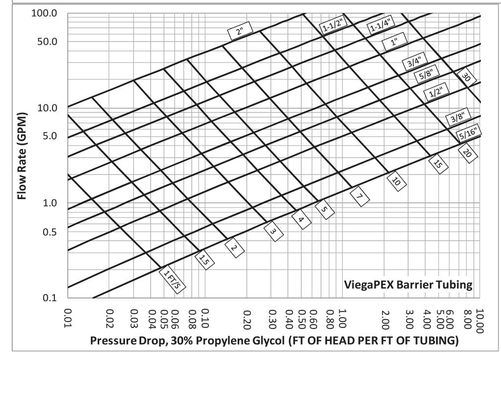
55 Pressure Testing The radiant or snow melt system must be tested before, during and after the concrete pour, and before the flooring finishes are applied. Air or water may be used as the test medium. The following procedure is recommended by Viega. Check the local building codes for compliance or additional test requirements. Do not use water as a test medium in situations where it may freeze. Check that all manifold connections are tight and properly sealed. Make sure all valves are in the open position to test the integrity of the entire system. Connect manifold pressurization kit (part # 21210) to the manifold(s). Pressurize the system to not less than 100 psi or 1.5 times the working pressure. After initial pressurization, ensure pressure has not dropped after 20 minutes. Fluctuations may occur due to temperature fluctuations and tubing expansion. If a drop has occurred add pressure to the system. Carry out test for a minimum of one hour. For leak detection, original Palmolive dishwashing soap may be used. (Use ratio of two oz. soap to one gal. water). Pressure must be maintained during the pour and floor covering installation. Once system is deemed leak-free the concrete pour and/or flooring finishes may be applied. Pressure Drop Example Determining the pressure drop in a system using a glycol solution is achieved in the same manner as for a 100% water system, except that different pressure drop charts must be used based on the % glycol solution. Pressure drop tables for piping using glycol solution are provided below. Also, don t forget to account for the pressure drop from accessories. Once the pressure drop and design flow rate are known, selecting a circulator involves the same steps as for a 100% water system. Maximum Circuit Length Tubing 25 Btu/h/ft Btu/h/ft " 250' 200'** ⅜" 300' 250'** ½" 400' 350'** ⅝" 500' 450'** ¾" 800' 750'** ** Maximum Btu/h/ft. 2 : Btu/h/ft. 2 Determine the pressure drop associated with 200 feet of ½" tubing at a maximum flow rate of one gpm: Locate desired one gpm flow rate for the tubing on the left vertical axis. Follow to the right until you reach the diagonal line corresponding to ½" tubing. Move down to the horizontal axis and read the pressure drop in feet of head per foot of tubing (~0.05 feet of head per foot of tubing). Multiply the pressure drop per foot by the length of tubing to find the feet of head for the circuit (0.05 x 200 = 10 feet of head). Account for all valves, fittings, heating source and other piping accessories (expansion tanks, air separators, etc.) when sizing circulator. 55

56 56

57 57
58 Approximate Friction Loss Allowances for Viega PEX Press and Viega ProPress Fittings in Feet of Straight Tube The tables below express friction loss for Viega fittings as equivalent lengths of tube, in feet. For example, a ¾" ProPress 90 elbow would impose the same friction as one foot of ¾" copper tube. Viega PEX Press Bronze Fittings (Equivalent Length of PEX Tubing in Feet) Size Coupling 90 Elbow Tee Run Tee Branch 5 /16" ⅜" ½" ⅝" ¾" " ¼" ½" " Viega PEX Press Polymer Fittings (Equivalent Length of PEX Tubing in Feet) Size Coupling 90 Elbow Tee Run Tee Branch ⅜" ½" ¾" " ¼" ½" " Viega ProPress Copper Fittings (Equivalent Length of Copper Tubing in Feet) Size 90 Elbow 45 Elbow Tee Run Tee Branch ½" ½ ½ ½ 1 ¾" 1 ½ ½ 2 1" 1 1 ½ 3 1¼" 2 1 ½ 4 1½" " ½" " "
59 Valve Sizing Chart Mixing Valve A mixing valve is controlled by an electronic actuator that receives a signal from a reset control. 3-Way This control varies the Valve with Electric temperature being supplied to Actuator the manifold by adjusting the amount of hot supply or cold return water that is permitted to flow through the valve. 3-Way Mixing Valve Cv Dimension Part No. Flow (GPM) Heat Capacity (BTU/h) Pressure Drop (psi) Pressure Drop (ft of Hd) 4.7 ¾" , , " , , ¼" , , ½" , , " , , Note: Heat capacity is based on using water at a ΔT of 20 F. The fluid used to calculate the pressure drop across the valve is water at 100 F. Diverting Valve A diverting valve is controlled by an electronic actuator that receives a signal from a reset control. This control varies the temperature Mixing Station being supplied to the manifold by adjusting the volume of return water being diverted back into the supply stream. Diverting Valve Cv Dimension Part No. Flow (GPM) Heat Capacity (BTU/h) Pressure Drop (psi) Pressure Drop (ft of Hd) 5.3 ¾" , , " , , ¼" , , ½" , , Note: Heat capacity is based on using water at a ΔT of 20 F. The fluid used to calculate the pressure drop across the valve is water at 100 F. 59
60 Thermostatic Mixing Valve Water temperature on the outlet of a thermostatic mixing valve is regulated by a built-in, non-electric temperature control. The non-electric control is set to the desired temperature and adjusts the amount of hot supply or cold return water that flows through the valve in order to maintain the desired supply temperature to the panel. Heat Exchanger Information Heat exchangers can be used in radiant and snow melt applications. Heat exchangers can be installed vertically or horizontally. A water strainer must be installed on the inlet connection (20-40 mesh recommended) to the heat exchanger. Water quality should be ph Heat exchangers should be piped in a counterflow arrangement. Ethylene or propylene glycol can be used with heat exchangers. (Glycol should be tested annually.) Heat exchangers using glycol should not exceed temperatures of 285 F on the inlet side of the exchanger. (On the source side do NOT exceed maximum recommendations of the PEX you are using.) To properly size a heat exchanger, determine the total BTU/h load/demand from the system and compare that with the table below. Side A Out Side A In Side B In Side B Out For snow melt system, 100 F in F out (40% Propylene Glycol) Connected to boiler, 180 F in F out Boiler Snow Melt Circuit Part Number Description BTU/h Pressure Drop Pressure Drop Flow (GPM) GPM (psi) (psi) x12,16 125, x12, , x12, , Note: For 200 F boiler water, use the above chart. 60
61 Circulator Sizing To select the correct circulator for the system, the flow and pressure drop must be calculated. Calculate desired flow rate being supplied by the circulator. GPM water = BTU/h(500xΔt) GPM 30% glycol = BTU/h(480xΔt) GPM 40% glycol = BTU/h(465xΔt) GPM 50% glycol = BTU/h(450xΔt) Locate the pressure drop on the left vertical axis. Locate the total system flow rate on the bottom horizontal axis. Follow to the intersection of both variables. Select a pump with a curve just higher than this intersection. If there are multiple pumps with curves higher than this point, then consider selecting the pump with the lowest watts for the best energy performance. Example A system design calls for a circulator that can move five gallons per minute at a pressure drop of 10 feet of head. Identify a Viega circulator that will satisfy this application. On the pump curve for model 12126, identify the intersection of 10 feet of head on the vertical axis and five gpm on the horizontal axis. This point is below the medium speed curve, which has a power consumption of 80 watts. On the pump curve for model 12127, identify the intersection of 10 feet of head on the vertical axis and five gpm on the horizontal axis. This point is below the low speed curve, which has a power consumption of 150 watts. Select model 12126, which will satisfy the design objectives and save 70 watts during its operation. Low Head HI MED Without Check Valve 12 Head (ft) 10 8 LOW Flow (GPM) Part Number SPEED AMPS WATTS HP HI / MED /25 LOW /25 61
62 High Head HI Without Check Valve 20 MED Head (ft) 15 LOW Flow (GPM) Part Number SPEED AMPS WATTS HP HI /6 MED /6 LOW /6 Note: This pump is used in Viega s mixing stations. Hydronic mixing block pump curve Speed 1 Speed 2 Speed 3 Head (Ft) Flow (USGPM) 62
63 Enhanced Mixing Station Performance* and operation mode selection AUTO ADAPT Operating range (maximum - minimum) *Hydraulic performance without check valve Performance and operation mode selection Pos. III II I ADAPT Description Push-button for selection of pump setting Every time the push-button is pressed, the circulator setting is changed High Fixed Speed Runs at a constant speed and consequently on a constant curve. In Speed III, the pump is set on the maximum curve under all operating conditions. Quick vent of the pump can be obtained by setting the pump to Speed III for a short period. Medium Fixed Speed Runs at a constant speed and consequently on a constant curve. In Speed II, the pump is set on the medium curve under all operating conditions. Low Fixed Speed Runs at a constant speed and consequently on a constant curve. In Speed I, the pump is set on the minimum curve under all operating conditions. Constant Pressure I The duty point of the pump will move left and right along the lowest constant-pressure curve depending on water demand in the system. The pump head (pressure) is kept constant, irrespective of the water demand. Constant Pressure II The duty point of the pump will move left and right along the middle constant-pressure curve depending on water demand in the system. The pump head (pressure) is kept constant, irrespective of the water demand. Constant Pressure III The duty point of the pump will move left and right along the highest constantpressure curve depending on water demand in the system. The pump head (pressure) is kept constant, irrespective of the water demand. AutoADAPT (Factory Setting) This function controls the pump performance automatically within the defined performance range (shaded area). AutoADAPT will adjust the pump performance to system demands over time. 63
64 Approximate power usage: Speed Setting Min. Max. High fixed speed III 39W 45W Medium fixed speed II 15W 30W Low fixed speed I 5W 8W Constant pressure 8W 45W Constant pressure 14W 45W Constant pressure 22W 45W AutoADAPT ADAPT 5W 45W Selecting the Percent Glycol Mixture Use table to determine the percent glycol solution necessary based on the freezing point of the solution as a function of the percent glycol by volume. Glycol 0% 10% 20% 30% 40% 50% (% by volume) Ethylene Propylene Freezing point ( F) of glycol solutions, based on type and percent by volume. The chart below can be used to figure volume per foot of tube for glycol considerations. Tubing Size SDR-9 PEX Tubing ASTM F876/F877/CTS-OD SDR-9 O.D. Wall Thickness Nom. I.D. Weight Per Ft. Vol. (gal.)/ 100 Ft. 5 16".430± ⅜".500± ½".625± ⅝".750± ¾".875± " 1.125± ¼" 1.375± ½" 1.625± " 2.125± Note: Dimensions are in English units. Tolerances are ASTM requirements. ViegaPEX is manufactured within these specifications. ViegaPEX Barrier tubing is available in both straight lengths and coils. 64
65 Dimensions and Physical Characteristics of Copper Tube: TYPE M Nominal Nominal Dimensions, inches Calculated Values (based on nominal dimensions) or Cross Standard Outside Inside Wall Sectional Weight of Weight Contents of Size, Diameter Diameter Thickness Area of Tube Only, of Tube Tube per linear Bore, pounds per & Water, ft. inches sq. inches linear ft. pounds per linear ft. Cu ft. Gal. ⅜" ½" ¾" " ¼" ½" " ½" " ½" " " " " " " Floor Coverings There are many types of finished flooring materials used in construction, though the four most popular types include: wood floors, tile, vinyl and carpet. When picking a finished floor material, the lower the R-value the more efficient the system. This is due to reduced water temperatures. Typically, based on their R-values, tile and wood floors will require lower water temperatures; carpet systems will require higher water temperatures (reference chart below) R = 0.25 R = 0.5 R = BTU/h/ft Of FLOOR SPACE R = 2.0 R = F 90 F 100 F 110 F 120 F 130 F 140 F 150 F 160 F 170 F 180 F 190 F SUPPLY WATER TEMPERATURE Note: Chart above is for 4" slab with ½" barrier tubing with R-5 insulation. 65
66 The chart below references some of the most common floor coverings with their R-values listed. R-Value Table Floor Coverings ⅛" ¼" ⅜" ½" ⅝" ¾" ⅞" 1" Building Board Gypsum or Plaster Board Plywood Particleboard, low density Particleboard, medium density Particleboard, high density Waferboard Wood Subfloor Cement Board Tile Ceramic Tile Marble Granite Slate Linoleum or Vinyl Rubber, hard Cork Tile Carpet Pad Waffled Sponge Rubber Synthetic Jute Bonded Urethane, 4 lb. density Bonded Urethane, 8 lb. density Prime Urethane, 2.2 lb. density Carpet Acrylic Level Loop Acrylic Level Loop w/foam Back Acrylic Plush Polyester Plush Nylon Level Loop Nylon Plush Nylon Shag Nylon Saxony Wool Plush Hardwood Ash Beech Cherry Elm Maple Oak Cedar Fir Hemlock Pine Redwood Spruce Engineered Flooring Laminated Parquet Flooring

67 Floor Coverings Another aspect to keep in mind when dealing with floor coverings is the floor surface temperature. The floor surface temperature should never exceed 85 F because the floor can be uncomfortable to the touch and/or potential flooring damage can occur. Please reference the chart below for calculating surface temperatures. Procedure Locate desired output (from LoopCAD or other source) on left vertical axis. Follow to the right until you reach the curve. Then move down to the horizontal axis and read the T between the room temperature and the floor surface temperature. Add the room temperature and the T to get the floor surface temperature. Example Output needed: 25 BTU/h/ft. 2 Room temperature: 68 F Temperature T (from chart): ~ 12 F Floor surface temperature: 68 F + 12 F = 80 F The floor surface temperature will be 80 F with 25 BTU/h/ft. 2 output and 68 F room temperature. Floor Surface Temperature Chart **For more information on installation, refer to: The flooring manufacturer and one of the following resources for installation guidance: - Standard Guidelines for the Design and Installation of Residential Radiant Panel Heating Systems. The Radiant Panel Association. - TCA Handbook for Ceramic Tile Installation. The Tile Council of North America. - The Marble Institute of America
68 Controls Basic Heating Control 68
69 69
70 Settings for Basic Heating Control Symptom Cause User Settings ROOM The desired room temperature. OUTDR DSGN The design outdoor temperature used for calculating heat loss. Obtained from the Design Outdoor Temperature Chart, or Viega s LoopCAD Software*. MIX DSGN The design supply water temperature obtained from the Supply Water Temperature / BTU Output Chart, or Viega s LoopCAD software. MIX INDR The design indoor air temperature used in the heat loss calculation* for the heating system (only visible with the Advanced/Installer DIP switch set to Advanced). Should be equal to ROOM, the desired room temperature. MIX MAX The maximum supply temperature for the mixing system (only visible with the Advanced/Installer DIP switch set to Advanced). This setting should not be relied upon for a safety high limit. WWSD Warm Weather Shutdown; the design outdoor air temperature at which the control operates only in exercising mode (only visible with the Advanced/Installer DIP switch set to Advanced). UNITS The units of measure that all of the temperatures are to be displayed in the control (either F or C). * See corresponding installation manuals, i.e. Concrete System, Climate Panel or Climate Trak, for appropriate charts. 70
71 New Viega Thermostats Viega non-programmable and programmable heat/cool thermostat Part numbers and The Viega non-programmable and programmable heat/cool thermostats are easy to install, easy to wire and easy to program. They can be used for single-stage heating and cooling projects. Part number pictured Thermostat applications guide Description Gas or Oil Heat Electric Furnace Heat Pump (No Aux. or Emergency Heat) Heat Pump (with Aux. or Emergency Heat) Multi-stage Systems Heat Only Systems Cool Only Systems Yes Yes Yes No No Yes Yes Technical data The display range of temperature F to 95 F (5 C to 35 C) The control range of temperature F to 90 F (7 C to 32 C) Loading Rate amp per terminal, 1.5 amp maximum all terminals combined Wiring Specifications Use shielded or non-shielded gauge thermostat wire. Display accuracy ±1 F Swing (cycle rate or differential).... Heating is adjustable from 0.2 F to 2.0 F. Cooling is adjustable from 0.2 F to 2.0 F. Power source to 30 VAC, NEC Class II, 50/60 Hz for hardwire (common wire) 3 wire, 3 wire with battery backup, 2 wire with battery, battery power from 2 AA alkaline batteries Operating ambient F to +105 F (0 C to +41 C) Operating humidity % non-condensing maximum Dimensions of thermostat "W x 4.4"H x 0.8"D Scheduling Non-programmable (not available) part number Programmable 5+1+1, part number
72 Thermostat wiring: Part number and If you are replacing a thermostat, make note of the terminal connections on the thermostat that is being replaced. In some cases the wiring connections will not be color coded. For example, the green wire may not be connected to the G terminal. 2. Loosen the terminal block screws. Insert wires then re-tighten terminal block screws. Power type 3 wire 3 wire with battery backup 2 wire with battery Terminal designations W - Heat relay Y - Compressor relay G - Fan relay O - Heat pump changeover valve energized in cooling RC - Transformer power for cooling RH - Transformer power for heating B - Heat pump changeover valve energized in heating C - Common wire from secondary side of cooling system transformer Wiring tips: RH & RC terminals For single transformer systems, leave the jumper wire in place between RH and RC. Remove jumper wire for two transformer systems. Heat pump systems If wiring to a heat pump, use a small piece of wire (not supplied) to connect terminals W and Y. C terminal The C (common wire) terminal does not have to be connected when the thermostat is powered by batteries. Wire specifications Use shielded or non-shielded gauge thermostat wire. Caution: Electrical hazard Failure to disconnect the power before beginning to install this product can cause electrical shock or equipment damage. Warning: All components of the control system and the thermostat installation must conform to Class II circuits per the NEC Code. 72


73 Programmable thermostat: part number Feature Feature Description LCD Will Show Filter Change Reminder This feature will flash FILT in the display after the elapsed run time to remind the user to change the filter. A setting of off will disable this feature. Room Temperature Calibration This feature allows the installer to change the calibration of the room temperature display. For example, if the thermostat reads 70 and you would like it to read 72 then select +2. Minimum Compressor On Time This feature allows the installer to select the minimum run time for the compressor. For example: A setting of 4 will force the compressor to run for at least 4 minutes every time the compressor turns on, regardless of the room temperature. Compressor Short Cycle Delay Cooling Swing Heating Swing The compressor short cycle delay protects the compressor from short cycling. This feature will not allow the compressor to be turned on for 5 minutes after it was last turned off. The swing setting, often called cycle rate, differential or anticipation, is adjustable. A smaller swing setting will cause more frequent cycles and a larger swing setting will cause fewer cycles. The swing setting, often called cycle rate, differential or anticipation, is adjustable. A smaller swing setting will cause more frequent cycles and a larger swing setting will cause fewer cycles. Adjustment Options Factory Default Settings You can adjust the filter change reminder from off to 2000 hours of runtime in 50-hour increments. Tap the second button from the top left side of the thermostat to display the current filter. You can adjust the room temperature display to read -4 F to +4 F above or below the factory calibrated reading. You can select the minimum compressor run time from off, 3, 4 or 5 minutes. If 3, 4 or 5 is selected, the compressor will run for at least the selected time before turning off. Selecting on will not allow the compressor to be turned on for 5 minutes after the last time the compressor was on. Select off to remove this delay. The cooling swing setting is adjustable from ±0.2 F to ±2 F. For example: A swing setting of 0.5 F will turn the cooling on at approximately 0.5 F above the setpoint and turn the cooling off at approximately 0.5 F below the setpoint. Off 0 F Off On 0.5 F 0.4 F The heating swing setting is adjustable from ±0.2 F to ±2 F. For example: A swing setting of 0.5 F will turn the heating on at approximately 0.5 F below the setpoint and turn the heating off at approximately 0.5 F above the setpoint. 73
74 Viega multifunctional heat/cool thermostat Part number The Viega multifunctional heat/cool thermostat is easy to install, easy to wire and easy to program. It can be used for three stages of heating and two stages of cooling. Thermostat applications guide Description Gas or Oil Heat Electric Furnace Heat Pump (No Aux. or Emergency Heat) Heat Pump (with Aux. or Emergency Heat) Multi-stage Systems Heat Only Systems Cool Only Systems Yes Yes Yes Yes Yes Yes Yes Technical data The display range of temperature F to 95 F (5 C to 35 C) The control range of temperature F to 90 F (7 C to 32 C) Loading Rate amp per terminal, 1.5 amp maximum all terminals combined Wiring Specifications Use shielded or non-shielded gauge thermostat wire. Display accuracy ±1 F Swing (cycle rate or differential) Heating is adjustable from 0.2 F to 2.0 F. Cooling is adjustable from 0.2 F to 2.0 F. Power source to 30 VAC, NEC Class II, 50/60 Hz for hardwire (common wire) 3 wire, 3 wire with battery backup, 2 wire with battery, battery power from 2 AA alkaline batteries Operating ambient F to +105 F (0 C to +41 C) Operating humidity % non-condensing maximum Dimensions of thermostat "W x 4.4"H x 1.1"D Scheduling , 7 day, none 74
75 Thermostat wiring: Part number If you are replacing a thermostat, make note of the terminal connections on the thermostat that is being replaced. In some cases the wiring connections will not be color coded. For example, the green wire may not be connected to the G terminal. 2. Loosen the terminal block screws. Insert wires then retighten terminal block screws. Power type 3 wire 3 wire with battery backup 2 wire with battery Wire specifications Use shielded or non-shielded gauge thermostat wire. Wiring Tips C terminal The C (common wire) terminal does not have to be connected when the thermostat is powered by batteries. NOTE: In systems with no emergency heat relay, a jumper can be installed between E and W2 to turn thermostat into a singlestage control. Terminal designations This thermostat is shipped from the factory to operate a conventional heating and cooling system. See the heat pump configuration step to configure the thermostat for heat pump applications. Terminal RC RH 2 Heat 2 Cool Conventional System Transformer power (cooling) Transformer power (heating) 2 Heat 2 Cool Heat Pump System Transformer power (cooling) Transformer power (heating) 3 Heat 2 Cool Heat Pump System Transformer power (cooling) Transformer power (heating) C Transformer common Transformer common Transformer common B Energized in heating Heat pump changeover valve energized in cooling O Energized in heating Heat pump changeover valve energized in cooling Heat pump changeover valve energized in heating Heat pump changeover valve energized in heating G Fan relay Fan relay Fan relay W/E First stage of heat Emergency heat relay Emergency heat relay Y First stage of cool First stage of heat & cool First stage of heat & cool Y2 Second stage of cool Second stage of cool Second stage of cool & second stage of heat W2 Second stage of heat Auxiliary heat relay, second stage of heat Auxilary heat relay, third stage of heat Warning: All components of the control system and the thermostat installation must conform to Class II circuits per the NEC Code. 75


76 Part number Technician Setup Steps Filter Change Reminder Room Temperature Calibration Minimum Compressor On Time Compressor Short Cycle Delay Cooling Swing Heating Swing Keypad Lockout This feature will flash FILT in the display after the elapsed run time to remind the user to change the filter. A setting of off will disable this feature. This feature allows the installer to change the calibration of the room temperature display. For example, if the thermostat reads 70 and you would like it to read 72 then select +2. This feature allows the installer to select the minimum run time for the compressor. For example: A setting of 4 will force the compressor to run for at least 4 minutes every time the compressor turns on, regardless of the room temperature. The compressor short cycle delay protects the compressor from short cycling. This feature will not allow the compressor to be turned on for 5 minutes after it was last turned off. The swing setting, often called cycle rate, differential or anticipation, is adjustable. A smaller swing setting will cause more frequent cycles and a larger swing setting will cause fewer cycles. The swing setting, often called cycle rate, differential or anticipation, is adjustable. A smaller swing setting will cause more frequent cycles and a larger swing setting will cause fewer cycles. Keypad lockout allows you to configure the thermostat so that none or some of the keys do not function. LCD Will Show Adjustment Options You can adjust the filter change reminder from off to 2000 hours of runtime in 50-hour increments. You can adjust the room temperature display to read -4 F to +4 F above or below the factory-calibrated reading. You can select the minimum compressor run time from off, 3, 4 or 5 minutes. If 3, 4 or 5 is selected, the compressor will run for at least the selected time before turning off. Selecting on will not allow the compressor to be turned on for 5 minutes after the last time the compressor was on. Select off to remove this delay. The cooling swing setting is adjustable from ±0.2 F to ±2 F. For example: A swing setting of 0.5 F will turn the cooling on at approximately 0.5 F above the setpoint and turn the cooling off at approximately 0.5 F below the setpoint. The heating swing setting is adjustable from ±0.2 F to ±2 F. For example: A swing setting of 0.5 F will turn the heating on at approximately 0.5 F below the setpoint and turn the heating off at approximately 0.5 F above the setpoint. Pick PA or FU PA = Partial keypad lockout, which locks all the keys except the + or keys. FU = Full keypad lockout, which locks out all the keys. Note: Keypad lockout instructions are below. Factory Default Settings Off 0 F Off On 0.5 F 0.4 F PA NOTE: To lock the keypad, hold down the + and keys for 3 seconds. You will see a lock in the display. To unlock the keypad, hold down the + and keys for 3 seconds. 76


77 Part number Technician Setup Steps (continued from the previous page) Heating Temperature Setpoint Limit This feature allows you to set maximum heat setpoint value. The setpoint temperature cannot be raised above this value. LCD Will Show Cooling Temperature Setpoint Limit F or C This feature allows you to set a minimum cool setpoint value. The setpoint temperature cannot be lowered below this value. This feature allows you to display temperatures in either Fahrenheit or Celsius. 12- or 24-Hour Clock Fan Operation Morning Recovery Program Options You can select either a 12- or 24-hour clock setting. Select GAS for systems that control the fan during a call for heat. Select ELEC to have the thermostat control the fan during a call for heat. This feature turns your system on before the WAKE programming time to ensure the environment is at the WAKE setpoint when the WAKE time period begins. The recovery period will change based on previous days knowledge. For 2 time periods, the system will turn on before the occupied programmable time. You can configure this thermostat to have a 7-day program, a program or nonprogrammable. Adjustment Options Use the + or key to select the maximum heat setpoint. Range 44 F - 90 F Use the + or key to select the minimum cool setpoint. Range 44 F - 90 F Select F for Fahrenheit or C for Celsius Use the + or key to select 12- or 24-hour clock. GAS or ELEC Use the + or key to turn on or off. Factory Default Settings 90 F 44 F F 12-Hour Clock GAS ON 5d Use the + or key to select 7d for 7 day, 5d for or 0d for nonprogrammable. 77


78 Part number Technician Setup Steps (continued from the previous page) Time Periods Display Light Contractor Call Number Beep Heat Pump Operating Modes Selection Gas Auxiliary for Heat Pump You can configure this thermostat to have 2 or 4 programmable time periods per day. 2 time periods is Occupied/ Unoccupied. 4 time periods is Wake, Leave, Return, Sleep. The display light can be configured to stay on at all times or come on when any key is pressed. NOTE: HARDWIRE ONLY Keeping the display light continually ON will greatly reduce battery life. Allows you to put your phone number in the display. You can choose ON or OFF When any key is pressed, an audible beep will sound. You can choose ON or OFF When turned on the thermostat will operate a heat pump. 1. EM. Heat will show as an option in the system switch. 2. Y will be first stage of heat & cool, W/E will be emergency heat relay & W2 will be auxiliary heat relay. You can configure the system switch for the particular application: Heat - Off - Cool, Heat - Off, Cool - Off, Heat-Off-Cool-Auto NOTE: EM, Heat will show if in heat pump mode. This option will turn the heat pump off 45 seconds after the auxiliary heat relay turns on. For 2-stage heat applications, the first stage will turn off 45 seconds after the auxiliary stage turns on. For 3-stage heat applications, the first and second stage will turn off 45 seconds after the auxiliary stage turns on. LCD Will Show Adjustment Options Use the + or key to select 2 or 4 time periods per day. OFF configures display light to come on when the light key or any other key is pressed. ON configures the display light to stay on. Use the + or key to turn on or off. If selected on, you will see the input screen after pressing next step. Use the + or key to select the desired number and the FAN or SYSTEM key to move from one character to another. See note below operation. ON is selected, the beep will sound. OFF is selected, there is no sound. OFF configures the thermostat for non-heat pump systems. ON configures the thermostat for heat pump systems. Use the + or key until the desired application is flashing. For heat pump systems that are dual fuel (use a gas furnace for auxiliary stage heat), you can turn this feature on to turn off the heat pump when the auxiliary stage of heating has been called for. Factory Default Settings 4 OFF OFF ON OFF Heat-Off-Cool OFF 78


 Stages of Heat Cooling Fan Delay Satisfy Setpoint Staging Delay You can configure the thermostat to operate a 3-stage heat")

79 Swing Setting Tip The second stage will turn on at 2x the swing setting. The second stage will turn off when 1x the swing is reached. For example, if the swing setting is.8 degrees for heating and the thermostat is set at 70 F, the first stage will turn on at approximately 69.2 F and the first will turn off at 70.8 F. If third stage is used, it will turn on at 3x the swing and turn off at approximately 2x the swing. NOTE: If contractor Call Number is selected ON, your phone number will show in the display if there has been a continuous call for heating or cooling for 24 hours or if the light button is held down for 3 seconds. To remove the phone number from the display, hold the light button for 3 seconds. Part number Technician Setup Steps (continued from the previous page) Stages of Heat Cooling Fan Delay Satisfy Setpoint Staging Delay You can configure the thermostat to operate a 3-stage heat pump system. 2H 2C = 2 heat, 2 cool 3H 2C = 3 heat, 2 cool LCD Will Show The cooling fan delay setting will delay the fan from coming on in cool mode and keep running after the compressor shuts off for a short time to save energy in some systems. This feature allows the thermostat to keep multiple stages of heat or cool energized until setpoint is satisfied. This feature allows a delay to occur when a second and third stage is needed. This allows the previous stage extra time to satisfy setpoint. Adjustment Options Use the + or key to change between 2 heat and 3 heat 2 heat will use Y1 as first stage and W2 as auxiliary. 3 heat will use Y1 as first stage, Y2 as second stage and W2 as auxiliary. You can select the Cooling Fan Delay from Off, 15, 30, 60 or 90 seconds. If 15, 30, 60 or 90 is selected the fan will not turn on for that many seconds when there is a call for cool and will run for that many seconds after satisfying a call for cool. Use the + or key to turn on or off. Factory Default Settings 2 Stages OFF OFF OFF Use the + or key to select OFF, 5, 10, 15, 30, 45, 62,
80 ISOLATED END SWITCH (5 AMP MAX) PUMP N/O COM N/C END SWITCH ZONE 4 RELAY ISOLATED END SWITCH (5 AMP MAX) PUMP N/O COM N/C END SWITCH ZONE 4 RELAY Viega thermostat wiring: Part number 15116, 15117, Thermostat Thermostat Thermostat C O B W RH RC G Y C O B W RH RC G Y C O B W/E W2 RH RC G Y Y2 Thermostat C C R W NTC A/B 120 V AC Power Supply L N R C POWER IN FUSE ZONE 4 PRIORITY OFF R W C R W C R W C R WC ON ZONE 1 ZONE 2 ZONE 3 ZONE 4 ZONE CONTROL (18060, 18062) WITH OPTIONAL PRIORITY ZONE 1 ZONE 2 ZONE 3 ZONE Part Numbers: 15116, and Connect the RC terminal from the thermostat to R terminal on the zone control 2. Connect the W terminal from the thermostat to W terminal on the zone control, for part number connect "W/E terminal from the thermostat to W terminal on the zone control 3. Connect the C terminal from the thermostat to the C terminal on the zone control Viega Yellow Yellow Red Red Red Red Viega Yellow Yellow LEGEND: Zone Controls Low Voltage Line Voltage Viega Yellow Yellow Red Red Red Red Yellow Yellow Viega Connecting Viega thermostats and zone valves to the Viega zone control Thermostat Thermostat Thermostat C O B W RH RC G Y C O B W RH RC G Y C O B W/E W2 RH RC G Y Y2 Thermostat C C R W NTC A/B LEGEND: Thermostat Low Voltage Line Voltage 120 V AC Power Supply L N R C POWER IN FUSE ZONE 4 PRIORITY OFF ON JUMPER JUMPER 3&4 3&4 IF PRIORITY IS USED R WC R WC R WC R WC ZONE 1 ZONE 2 ZONE 3 ZONE 4 ZONE CONTROL (18060, 18062) WITH OPTIONAL PRIORITY ZONE 1 ZONE 2 ZONE 3 ZONE 4 Part Numbers: 15116, and Connect the RC terminal from the thermostat to R terminal on the zone control 2. Connect the W terminal from the thermostat to W terminal on the zone control, for part number connect W/E terminal from the thermostat to W terminal on the zone control 3. Connect the C terminal from the thermostat to the C terminal on the zone control Viega POWERHEAD (15061, 15070) 2 WIRE, 24 V, FOR USE WITH STAINLESS MANIFOLD Viega Viega Viega Connecting Viega thermostats to the Viega zone control Yellow Yellow Red Red Red Red Yellow Yellow Red Red Yellow Yellow POWERHEAD (15064, 15069) 4 WIRE, 24 V, FOR USE WITH STAINLESS MANIFOLD 80
81 Part number 15116, 15117, Four powerheads may be connected to each thermostat Viega Thermostat C RH O RC B G W Y TO T-T BOILER CONTACT, PUMP RELAY OR OTHER AUXILIARY DEVICE REQUIRING CONTACT CLOSURE. SEE NOTE 2. Red Red Yellow Yellow LEGEND: Thermostat Low Voltage Line Voltage 120 V AC Power Supply N Class II Transformer C Connecting Viega thermostats to four wire powerheads Note: Part number "W" terminal is labeled "W/E" L R LEGEND: Thermostat Low Voltage Line Voltage Thermostat Viega Viega C O B W RH RC G Y Connecting Viega thermostats to two wire powerheads 120 V AC Power Supply N L Class II Transformer C R Four powerheads may be connected to each thermostat 81

82 Viega Zone Valve Viega zone valves are used to control the flow of fluid within a hydronic heating or cooling system. They do so by opening when there is a thermostat demand and closing when the demand has been met. Viega zone valves are available in ¾" and 1", with three different connection types, ProPress x ProPress, ProPress x PEX Press and solder x PEX Press. 2.09" 2.42" Dimensions D E 1.74" 2.01" 0.28" Installation Height Technical Data: Voltage: Volts Max inrush current: ma, for 2 min. Operating power: w Closing/opening time:.... Approximately 3 min. Max pressure differential:. 50 psi Cv rating ¾" valve: Cv rating 1" valve: Fluid temperature: F Stem travel: mm Actuating force: lbs Body material: Low zinc bronze, alloy C84400 C B A Zone Valve Dimensions Part No. Description A B C D E ¾" Solder x PEX Press 4.70" 3.25" 2.50" 3.60" 4.25" " Solder x PEX Press 6.25" 4.60" 3.60" 3.75" 4.60" ¾" PP X PP 5.60" 3.80" 2.50" 3.60" 4.25" " PP X PP 6.86" 5.20" 3.60" 3.75" 4.60" ¾" PP X PEX Press 5.10" 3.80" 2.50" 3.60" 4.25" " PP X PEX Press 6.62" 5.28" 3.60" 3.75" 4.60" On/off indicator The zone valve powerhead has a cylinder on the top that will raise and expose blue when the valve is open. You will be unable to see any blue when the valve is in its normal closed position. Initially open function The zone valve is delivered in the open position. This allows for easier installations and also allows for the installer to pressure and flow test each circuit before connection to the power. This function is disengaged automatically after the first 6 minutes of powered use. 82
Viega Concrete System Installation Manual
 Viega Concrete System Installation Manual The global leader in plumbing, heating and pipe joining systems Welcome By choosing to install a Viega Concrete System, you have joined the ranks of heating system
Viega Fire Protection Systems. Safety starts here
 Viega Fire Protection Systems Safety starts here 1 Viega Fire Protection Systems SAFETY FOR BUSINESS OR HOME Viega MegaPress fittings The only press fitting for black iron pipe, Viega MegaPress is suitable
ProRadiant Combiflex. Viega's Hydronic Solution Installation Manual 2013
 ProRadiant Combiflex Viega's Hydronic Solution Installation Manual 2013 Contents 1 System Advantages and Benefits 1.1 Combiflex system concept...3 1.2 Application benefits...4 1.3 Manifold/mixing equipment
Viega ProPress Marine Systems Safe, secure connections across the seas.
 Viega ProPress Marine Systems Safe, secure connections across the seas. Your connection to innovation Viega adds traps and draining products for sinks and bathtubs to our lineup. The first PEX radiant
General System Layout Sketch
 General System Layout Sketch EZ-37 Solar Panels PV panel Glycol Fill Valve Expansion Tank ` 1 Introduction This document describes how to install a Heliatos GH type solar water heating system. These systems
General System Layout Sketch
 General System Layout Sketch SW-38 Solar Panel(s) Hot Water Cold Water PV panel Glycol RV Water Heater WITH built in Heat Exchanger Water Ports ` Glycol Fill Valve 1 Pump Solar Powered Expansion Tank Glycol
Viega Fire Sprinkler Systems
 Viega Fire Sprinkler Systems The global leader in plumbing, heating and pipe joining systems Viega adds traps and draining products for sinks and bathtubs to our lineup. The first PEX radiant floor heating
Model ESFR-17 Dry Type Pendent Sprinklers Early Suppression Fast Response 16.8 K-factor General Description
 Technical Services 800-381-9312 +1-401-781-8220 www.tyco-fire.com Model ESFR-17 Dry Type Pendent Sprinklers Early Suppression Fast Response 16.8 K-factor General Description The TYCO Model ESFR-17 Dry
Installation & Operation Instructions
 Installation & Operation Instructions Carefully remove the fully assembled pump from the box and uncoil it on the ground. Lower the pump into the well, below the waterline, but several feet up from the
Making Crimp Connections
 Making Crimp Connections Cut tube off square (90 ) with a tube cutter. Tube Cutter Slide the PEX crimp ring over the end end of the tube. BE SURE the crimp ring is centered over the PEX barb. Slide the
Installation Manual PS-225 & PS-275
 Installation Manual PS-225 & PS-275 Table of Contents Pre-Uncrating Checklist... 1 Verifying System Requirements... 2 Verifying System Direction... 2 Verifying the Electrical Requirements... 2 Removal
Installation Instructions. For the 18 Built-In Dishwasher and Front Color Panels
 Installation Instructions For the 18 Built-In Dishwasher and Front Color Panels Printed in USA 154232102 Before You Begin DO NOT INSTALL DISHWASHER UNTIL YOU HAVE READ ALL INSTRUCTIONS. FOR YOUR SAFETY,
WARM WATER UNDERFLOOR HEATING SYSTEMS. Guidance Notes
 WARM WATER UNDERFLOOR HEATING SYSTEMS Guidance Notes 02 WARM WATER UNDERFLOOR HEATING SYSTEMS Introduction Underfloor heating systems consist of a series of pipes which are integrated into the floor structure
General System Layout Sketch
 General System Layout Sketch EZ-37 Solar Panels PV panel Can use Standard Copper, CPVC or PEX Pipes Pump Existing Water Heater Bottom Feed Connector 1 Introduction This document describes how to install
I-VICFLEX.AB4. Victaulic VicFlex Style AB4 Sprinkler Fitting for Hat Furring Channel Ceiling Systems WARNING INSTALLATION INSTRUCTIONS
 INSTALLATION INSTRUCTIONS I-VICFLEX.AB Victaulic VicFlex Style AB Sprinkler Fitting for Hat Furring Channel Ceiling Systems Read and understand all instructions before attempting to install any Victaulic
BASE-RAY CAST IRON BASEBOARD RADIATION
 INSTALLATION MANUAL FOR BASE-RAY CAST IRON BASEBOARD RADIATION TABLE OF CONTENTS PAGE 2 RATINGS 4 ASSEMBLY CHART 5 SYSTEM TYPES 6 SERIES LOOP SYSTEMS 7 SERIES LOOP DESIGN 8 INSTALLATION DETAILS 9 INSTALLATION
IMPORTANT INFORMATION. Revised Dishwasher Installation Instructions
 IMPORTANT INFORMATION Revised Dishwasher Installation Instructions To obtain a revised copy of the entire Dishwasher User s Manual, go to www.eurotechappliances.com. SPECIAL EDITION 11-20-02 SAVE THESE
New Products in this Catalog
 New Products in this Catalog X-PERT Tubing - pg. 4 3-way Mixing Valves - pg. 50 Crete-Heat Insulated Floor Panels - pg. 10 3 & 4-way Mixing Valve Actuators - pg. 50 Residential Copper Manifolds - pg. 22
Viega PEX Water Systems Installation Manual
 Viega PEX Water Systems Installation Manual The global leader in plumbing, heating and pipe joining systems Welcome Viega, heritage of quality, vision for the future Viega s heritage of superiority demands
Hydronic Radiant and Snowmelt. Product Catalog. Living full of energy
 Hydronic Radiant and Snowmelt Product Catalog Tubing Panel Systems Manifold and Mixing Stations Fittings and Tools Valves and Controls Living full of energy Hydronic and Radiant Heating Product Catalog
PureFlow. PureFlow. Fittings system This section doesn t meet California AB1953, Vermont ACT 193 and NSF 61 Annex G Standards.
 Fittings system This section doesn t meet California AB1953, Vermont ACT 193 and NSF 1 Annex G Standards. 11 PEX Manifold Plumbing Systems # of Outlets: Dimension (hot,cold) MANABLOC -BRONZE PEX PRESS
ProRadiant Manifolds, Stations and Fittings
 Manifolds, Stations and Fittgs 197 Staless Manifolds and Accessories # of Outlets STAINLESS MANIFOLD - SHUT-OFF / BALANCING / FLOW METERS These preassembled 1-1/4" diameter staless supply and return manifolds
Installation Manual PS-200 & PS-201
 Installation Manual PS-200 & PS-201 Table of Contents Pre-Uncrating Checklist... 1 Verifying System Requirements... 2 Verifying System Direction... 2 Verifying the Electrical Requirements... 2 Removal
IdealFILM. Do-It-Yourself Installation Manual
 IdealFILM Do-It-Yourself Installation Manual Comfortable Warm Floors Benefits of using RSG Idealfilm Heats from the floor up for better heat distribution throughout the room No dust or allergens blown
SECTION RADIANT HEATING UNITS
 PART 1 GENERAL 1.01 SECTION INCLUDES A. Hydronic radiant panel heaters. B. Electric radiant ceiling panel heaters. C. Radiant heating hydronic piping. SECTION 23 8300 RADIANT HEATING UNITS D. Outdoor electric
POTABLE PIPING SYSTEM
 POTABLE PIPING SYSTEM Designed Especially for Contractors PRODUCT INSTALLATION GUIDE BOW SUPERPEX JUne 2017 PRODUCT INSTALLATION GUIDE IMPORTANT NOTICE The information in this manual was gathered from
INSTALLATION INSTRUCTIONS UNDERCOUNTER DISHWASHERS
 INSTALLATION INSTRUCTIONS UNDERCOUNTER DISHWASHERS VIKING 111 Front Street Greenwood, Mississippi 38930 USA (662) 455-1200 IMPORTANT - PLEASE READ AND FOLLOW Before beginning - please read these instructions
B. Product Data: Provide manufacturers catalogue information. Indicate valve data and ratings.
 DIVISION 21 21 05 00 COMMON WORK RESULTS FOR FIRE SUPPRESSION PART 1 GENERAL 1.1 SECTION INCLUDES A. Pipe, fittings, sleeves, escutcheons, seals, and connections for sprinkler systems. 1.2 RELATED REQUIREMENTS
WARNING. Flexible Hose AH2 With AB6 With AB6. AH2-CC With AB6 With AB6
 INSTALLATION INSTRUCTIONS I-VICFLEX. Victaulic VicFlex Sprinkler Fittings: Style Bracket Assembly with Models V33,, or V40 Dry Sprinklers Read and understand all instructions before attempting to install
Built-In Dishwasher. Installation Instructions. BEFORE YOU BEGIN Read these instructions completely and carefully. IMPORTANT The dishwasher MUST be
 Installation Instructions Built-In Dishwasher If you have questions, call 800.GE.CARES (800.432.2737) or visit our website at: www.ge.com BEFORE YOU BEGIN Read these instructions completely and carefully.
Model ESFR-17 Dry Type Pendent Sprinklers Early Suppression Fast Response 16.8 K-factor General Description
 Worldwide Contacts www.tyco-fire.com Model ESFR-17 Dry Type Pendent Sprinklers Early Suppression Fast Response 16.8 K-factor General Description The TYCO Model ESFR-17 Dry Type Pendent Sprinklers (TY7229)
HVAC BASIC MATERIAL AND METHODS 1.01 RELATED CORNELL DESIGN AND CONSTRUCTION STANDARDS
 230500 HVAC BASIC MATERIAL AND METHODS PART 1 GENERAL 1.01 RELATED CORNELL DESIGN AND CONSTRUCTION STANDARDS A. Section 230000 Basic HVAC Requirements B. Section 230523 Valves C. Section 230510 Chilled
Installation Instructions
 GE Consumer & Industrial Appliances Installation Instructions Junction Box Cover Within this user bag, you will find a junction box cover and a #10 hex head screw used to attach the junction box cover
PRE-ASSEMBLED RADIANT CONTROL PANEL INSTALLATION MANUAL
 FloorHeat PRE-ASSEMBLED RADIANT CONTROL PANEL INSTALLATION MANUAL Thank you for purchasing this radiant control panel assembly. Following are some important notes that will make the installation successful.
GASEOUS HYDROGEN SYSTEMS
 CHAPTER 7 GASEOUS HYDROGEN SYSTEMS SECTION 701 GENERAL 701.1 Scope. The installation of gaseous hydrogen systems shall comply with this chapter and Chapters 30 and 35 of the Fire Compressed gases shall
UPONOR Ltd. Specification for UPONOR Q&E PEX Shrinkfit Plumbing Systems
 UPONOR Ltd Specification for UPONOR Q&E PEX Shrinkfit Plumbing Systems Reference Page(s) UPONOR Q&E PEX 2 Operating Conditions 2 Pipe Properties 2 Fittings Range 3 Radiator Heating Systems 3 H&C Water
TECHNICAL SERVICE GUIDE
 GE Consumer Home Services Training TECHNICAL SERVICE GUIDE LOKRING Connectors Pub # 31-9067 01/01 IMPORTANT SAFETY INFORMATION Before cutting or using a torch on refrigerant tubes, recover the refrigerant
A. Air Handling Units shall be designed to the specific requirements of the application: Recirculation or 100% Makeup.
 SECTION 23 70 00- CENTRAL HVAC EQUIPMENT PART 1: GENERAL 1.1 PURPOSE: A. This standard is intended to provide useful information to the Professional Service Provider (PSP) to establish a basis of design.
Viega ProPress System
 Viega ProPress System Viega The global leader in plumbing and heating systems. Viega adds traps and draining products for sinks and bathtubs to our lineup. The first PEX radiant floor heating in the U.S.,
B. Galvanized-Steel-Sheet Sleeves: inch minimum thickness; round tube closed with welded longitudinal joint.
 (816) 373-4878 U1208-01/FAI29-029 (573) 751-2624 SECTION 2 105 17 - SLEEVES AND SLEEVE SEALS FOR FIRE-SUPPRESSION PIPING PART 1 - GENERAL 1.1 RELATED DOCUMENTS A. Drawings and general provisions of the
Ductless Split Air Conditioner
 Ductless Split Air Conditioner Installation Manual Indoor HSU09VHG(DB)-W HSU12VHG(DB)-W HSU18VHH(DB)-W HSU24VHG(DB)-W Outdoor HSU09VHG(DB)-G HSU12VHG(DB)-G HSU18VHH(DB)-G HSU24VHG(DB)-G Table of Contents
Top Control Dishwasher
 INSTALLATION GUIDE Top Control Dishwasher NS-DWH2BS8/NS-DWH2SS8/NS-DWR2BS8/NS-DWR2WH8/NS-DWR2SS8 Before using your new product, please read these instructions to prevent any damage. Contents Introduction......................................................................................................
Installation Manual. Vent Kit for Condensing Tankless Gas Water Heater
 Installation Manual NORITZ AMERICA CORPORATION Vent Kit for Condensing Tankless Gas Water Heater Model: N-FlexKit2"-35 Applicable Model NRC663-FSV Potential dangers from accidents during installation and
Gardian W51. Approvals
 Gardian W51 120 V pre-assembled electric heating cables for pipe freeze protection and roof & gutter de-icing Installation Instructions Description Gardian W51 120 V pre-assembled self-regulating heating
Daikin Water Cooling, Heating, and High Capacity Booster Coils
 Installation and Maintenance Manual IM 900 Daikin Water Cooling, Heating, and High Capacity Booster Coils Group: Applied Air Part Number: IM 900 Date: February 2008 Types HI-F5, E-F5 2008 Daikin International
Vent Kit for Condensing Tankless Gas Water Heater
 Installation Manual NORITZ AMERICA CORPORATION Vent Kit for Condensing Tankless Gas Water Heater Model: EZ2FVK-1 (Flex Vent 2" Kit 25 feet) Potential dangers from accidents during installation and use
Installation Instructions
 Installation Instructions Built-In Dishwasher If you have questions, call 800-944-9400(US),800-245-8352(Canada)or visit our website at: www.frigidaire.com BEFORE YOU BEGIN Read these instructions completely
Installation Instructions
 GE Consumer & Industrial Appliances Installation Instructions Junction Box Cover Within this user bag, you will find a junction box cover and a #10 hex head screw used to attach the junction box cover
Model ESFR K-factor Dry Type Pendent Sprinklers Early Suppression, Fast Response General Description
 Worldwide Contacts www.tyco-fire.com Model ESFR-17 16.8 K-factor Dry Type Pendent s Early Suppression, Fast Response General Description TYCO Model ESFR-17 Dry Type Pendent s are Early Suppression, Fast
Installation Instructions
 Installation Instructions Built-In Dishwasher If you have questions, call 800-GECARES or visit our website at: www.geappliances.com BEFORE YOU BEGIN Read these instructions completely and carefully. IMPORTANT
INSTALLATION AND OPERATION MANUAL
 F OR I NGROUND P OOLS INSTALLATION AND OPERATION MANUAL How Solar Pool Heating Works Why SunHeater TM Works Best Using your pool pump, water is automatically pumped through the solar collectors. The water
Installation Instructions
 Installation Instructions KFN 9855 ide en - CA Installation, repair and maintenance work should be performed by a Miele authorized service technician in accordance with national and local safety regulations
ELECTRIC COOKTOP INSTALLATION INSTRUCTIONS
 INSTALLATION AND SERVICE MUST BE PERFORMED BY A QUALIFIED INSTALLER. IMPORTANT: SAVE FOR LOCAL ELECTRICAL INSPECTOR'S USE. READ AND SAVE THESE INSTRUCTIONS FOR FUTURE REFERENCE. U.S.A. WARNING FOR YOUR
Model ESFR K-factor Dry Type Pendent Sprinklers Early Suppression, Fast Response General Description
 Worldwide Contacts www.tyco-fire.com Model ESFR-17 16.8 K-factor Dry Type Pendent s Early Suppression, Fast Response General Description TYCO Model ESFR-17 Dry Type Pendent s are Early Suppression, Fast
IH091: Home Wastewater Disposal System Installation Instructions & Warranty Information
 IH091: Home Wastewater Disposal System Installation Instructions & Warranty Information The Environment One grinder pump is a well-engineered, reliable and proven product. Proper installation ensures years
Installation Instructions
 Installation Instructions For the 18" Built-In Dishwasher Sears, Roebuck and Co. Sears Canada, Inc. Hoffman Estates, IL 60179 U.S.A. Toronto, Ontario, Canada M5B 2B8 154435201 Before You Begin DO NOT INSTALL
Installation Instructions Built-In Dishwasher
 GE Consumer & Industrial Appliances Installation Instructions Built-In Dishwasher If you have questions, call 800.GE.CARES (800.432.2737) or visit our website at: www.ge.com BEFORE YOU BEGIN Read these
GENIE CLIP TYPE RST. Resilient Sound Isolation Clip INSTALLATION INSTRUCTIONS
 GENIE CLIP TYPE RST Resilient Sound Isolation Clip INSTALLATION INSTRUCTIONS NOTE If at any time there is a question or concern as to the installation methods please contact Pliteq Inc or your local representative.
Socket Heat Fusion Techniques. A Guide for Instruction and Training in Vanguard Socket Heat Fusion
 Socket Heat Fusion Techniques A Guide for Instruction and Training in Vanguard Socket Heat Fusion TABLE OF CONTENTS This brochure has been developed to assist those responsible for socket fusion joining
C O D E S & A M M E N D M E N T S
 SEVIER COUNTY UTILITY DISTRICT SEPTEMBER 2, 2014 Sevier County Utility District has adopted the 2009 International Fuel Gas Code for gas inspections. The following pages contain frequently used codes and
Dishwasher Installation Instructions DW 24XT/DW 24XV
 Dishwasher Installation Instructions DW 24XT/DW 24XV Installation Instructions Dishwasher BEFORE YOU BEGIN Read these instructions completely and carefully. IMPORTANT Observe all governing codes and ordinances.
... Green Building Details
 Combining Solar HW with Radiant Floor using a Demand Water Heater back-up and a Tempering Tank with a line voltage three-way valve to prevent heating the solar storage with the gas DHW... A short list
Overview Frost Heave Prevention for Freezer floors on ground.
 PLEASE NOTE The floor sensor MUST be installed such that it may be REMOVED for service if required! The sensor probe should be installed into a conduit with no more than one wide-angle bend. This should
Casper Hoop House Workshop 12 Ft. x 36 Ft. Del Jimenez. 12ft x 36ft Hoop House 2
 Casper Hoop House Workshop 12 Ft. x 36 Ft. Del Jimenez 12ft x 36ft Hoop House 2 Hoop House 12 Ft. x 36 Ft. HOOP HOUSE The Hoop House, Cold Frame and High Tunnel can be basically the same structure with
Viega Industrial Solutions
 Viega Industrial Solutions The global leader in plumbing, heating and pipe joining systems A heritage of better ideas since 1899 Only the Viega Group offers a heritage of true innovation, from our humble
Zurn Hydronics Prices Effective 1/01/06
 CURRENT MFG LIST Radiant Tubing / Manifolds / Tools Boxed Barrier Pex Tubing QUE/QHR2PC1000X 3/8" x 1000' Roll (Barrier) $1,085.45 QUE/QHR2PC500X 3/8" x 500' Roll (Barrier) $542.73 QUE/QHR4PC500X 3/4"
Fleck 5600 SXT. Installation Guide. Make a list of all of the plumbing fittings needed to install; a typical list looks like this:
 Installation Guide Before you assemble your new system, be sure that the following conditions have been met for placement of your softener: Getting Started Level, firm surface, such as concrete, on which
pushing the tube into the rear of the water outlet housing with a slight twisting motion to evenly distribute the adhesive. After cleaning off any ext
 I chose an original FE expansion tank that had the filler neck on the driver's side of the tank but still had the radiator hose outlet facing the passenger side. I figured using such a tank would afford
Electrical cable Water supply tube Fittings for tube Coupler Teflon tape. Hole saw min. 2½" bit
 Installation Parts and Tools Parts not Provided Electrical cable Water supply tube Fittings for tube Coupler Teflon tape Air gap Wire nuts for 6-gauge wiring Hose clamp ⅞" UL approved strain relief Electrical
BUILT-IN DISHWASHER INSTALLATION INSTRUCTIONS
 BUILT-IN DISHWASHER INSTALLATION INSTRUCTIONS PLEASE READ COMPLETE INSTRUCTIONS BEFORE YOU BEGIN LEAVE INSTALLATION INSTRUCTIONS AND USER'S GUIDE WITH OWNER ALL ELECTRIC WIRING AND PLUMBING MUST BE DONE
D. NEMA Compliance: Provide electric motors and components which comply with NEMA standards.
 PART 1: GENERAL 1.01 Purpose: A. This standard is intended to provide useful information to the Professional Service Provider (PSP) to establish a basis of design. The responsibility of the engineer is
2/4TXCC037BC3HCA 2/4TXCB042BC3HCA 4TXCC044BC3HCA 2/4TXCC043BC3HCA 2/4TXCB048BC3HCA
 18- AH39D1-4 Cased Aluminum "Convertible" Coils 2/4TXCA018BC3HCA 2/4TXCA024BC3HCA 2/4TXCB025BC3HCA 2/4TXCB031BC3HCA 4TXCB032BC3HCA 2/4TXCB036BC3HCA ALL phases of this installation must comply with NATIONAL,
Installation Manual. Vent Kit for Condensing Tankless Gas Water Heater
 Installation Manual NORITZ AMERICA CORPORATION Vent Kit for Condensing Tankless Gas Water Heater Model: N-FlexKit2"-35 Applicable Model NRC663-FSV Potential dangers from accidents during installation and
Walk-in Refrigerated Rooms. An Overview of Requirements, Options and Construction Details
 Walk-in Refrigerated Rooms An Overview of Requirements, Options and Construction Details Definition A refrigerated room is a stand alone structure designed to hold products at either a medium temperature
DRY CHARGE UNITS. 1.5 to 5 Tons AIR CONDITIONERS LCS13DC PRODUCT SPECIFICATIONS L C S 13 DC MODEL NUMBER IDENTIFICATION
 CONDITIONERS DRY CHARGE UNITS PRODUCT SPECIFICATIONS Bulletin No. 20636 May 204 Supersedes March 202.5 to 5 Tons MODEL NUMBER IDENTIFICATION L C S 3 DC - 036-230 - 2 Lennox Minor Revision Number Air Conditioner
215 Gallon Waste Oil Tank With Bypass Regulator Installation Instructions
 215 Gallon Waste Oil Tank With Bypass Regulator Installation Instructions Lanair Products LLC 4109 Capital Circle Janesville, Wisconsin 53546 1-888-370-6531 www.lanair.com BEFORE YOU BEGIN INSTALLATION...
Parts & Material Included
 O² Hydro Well System Installation, Use & Care Guide Parts & Material Included 1. Funnel 11. Drain Line 21. Air Head 2. Media Tank Distributer Tube 12. Air Release 22. Drain Fitting 3. Air Tank Distributer
Installation Instructions PRO SERIES
 Installation Instructions PRO SERIES If you are a plumber installing this unit, please leave this owners manual & warranty card with the owner when you finish the installation. Thank You! DO NOT USE THIS
PolyMax H2-24 Dutch Bucket System
 11234 PolyMax H2-24 Dutch Bucket System *Actual system may differ. PolyMax Dutch Buckets Versatile PolyMax Dutch Buckets are ideal for both small- and large-scale hydroponic growing. 2017 FarmTek All Rights
Installation Instructions. (Applicable to all front door models)
") COOL CELL Passive Temperature Regulating Battery Enclosures Installation Instructions (Applicable to all front door models) CONTENTS 1. Safety Instructions 2. General Information 3. Cool Cell Description
COOL CELL Passive Temperature Regulating Battery Enclosures Installation Instructions (Applicable to all front door models) CONTENTS 1. Safety Instructions 2. General Information 3. Cool Cell Description
INSTALLATION INSTRUCTIONS TXV Horizontal Duct Coils EHD
 TXV Horizontal Duct s EHD These instructions must be read and understood completely before attempting installation. It is important that the Blower and Duct System be properly sized to allow the system
RESCOM 2100 HOT WATER BASEBOARD RADIANT HEATING Unique, slim-design baseboard radiators
 RESCOM 2100 HOT WATER BASEBOARD RADIANT HEATING www.b Unique, slim-design baseboard radiators The RESCOM 2100 system is unlike traditional baseboard heating systems. Smooth flat panels are easily secured
COMMERCIAL HYDRONIC PRODUCTS A MESTEK COMPANY. Convectors STEAM AND HOT WATER RADIATION CC-13
 COMMERCIAL HYDRONIC PRODUCTS A MESTEK COMPANY Convectors STEAM AND HOT WATER RADIATION CC-13 Sterling Convectors are engineered for both forced hot water and two-pipe steam heating system installation
Potable Piping System
 Page, May 2006 Potable Piping System BOW SUPERPEX is designed with three distinct layers for ultimate protection. The middle layer provides chlorine resistance as well as UV light exposure resistance plus
Installation Instructions for. OmniFount
 Installation Instructions for OmniFount Congratulations, you have just purchased the finest watering fountain on the market. This unit is built to give you excellent service when properly installed and
Direct Exhaust Venting Kit Instructions
 CONDENSING GAS BOILER 220/299/300/399 Direct Exhaust Venting Kit Instructions Evergreen 220/299/300/399 Kit part number 383-500-769 STOP! Read before proceeding Hazard definitions The following defined
DIVISION 23 HVAC Hydronic Piping Systems
 General Information Programming/ Design Bidding/ Preconstruction Installation/ Construction Closeout/ Warranty QA/QC Checklist Construction Services DIVISION 23 HVAC 23 21 13 Hydronic Piping Systems 01
INSTALLATION INSTRUCTIONS WARRANTY
 QT FLOW CENTER INSTALLATION INSTRUCTIONS Fig. 1. Low Head Pump Center Flow Chart Fig. 2. High Head Pump Center Flow Chart NOTE: Read the entire instruction manual before starting the installation. WARRANTY
568X, 587X, 588X Series
 Please read and save this Repair Parts Manual. Read this manual and the General Operating Instructions carefully before attempting to assemble, install, operate or maintain the product described. Protect
CONNECTION SYSTEM AUGUST Reliance Worldwide USA
 CONNECTION SYSTEM Reliance Worldwide USA AUGUST 2010 1-877-700-4242 www.sharkbitepro.com the sharkbite Connection system includes push-fit and barb products and pex tubing. Contents Introduction and Applications...........................................
Non-RTD Hot Melt Hose Replacement
 Instruction Sheet P/N 7C 0 Safety WARNING: System pressurized! Relieve system hydraulic pressure before breaking any hydraulic connection or seal. Failure to relieve the system hydraulic pressure can result
SYSTEM MANUAL Description
 SYSTEM MANUAL Description PUCK is a revolutionary fire suppression system offering discrete protection coupled with industry leading pricing, efficient system design and easy install. PUCK s lightweight
Electric Floor Warming Systems Installation and Operation Instructions. Mat Heating Systems and Cable Heating Systems. UL Listed for USA and Canada
 Electric Floor Warming Systems Installation and Operation Instructions Mat Heating Systems and Cable Heating Systems UL Listed for USA and Canada Thank you for your purchase of a Warming Systems electric
G3/8" DIN ISO 228 THREAD SHOULDER AND DUST CAP MATING SURFACE. STYLE H ESCUTCHEON (SEPARATELY ORDERED) 85 mm DIA. (3-3/8")
 85 mm DIA. (3-3/8)") Worldwide Contacts www.tyco-fire.com Model FSC 80 K-factor Flush Sprinkler, Pendent Quick Response, Standard Coverage General Description The TYCO Model FSC 80 K-factor Flush Sprinkler is a quick response
Worldwide Contacts www.tyco-fire.com Model FSC 80 K-factor Flush Sprinkler, Pendent Quick Response, Standard Coverage General Description The TYCO Model FSC 80 K-factor Flush Sprinkler is a quick response
INSTALLATION, OPERATION, AND MAINTENANCE MANUAL
 INSTALLATION, OPERATION, AND MAINTENANCE MANUAL TUBE AXIAL FANS BTA, WTA, HTA, DDA The purpose of this manual is to aid in the proper installation and operation of the fans. These instructions are intended
R-124 MANUAL LOKRING W
 R-124 TECHNICAL SERVICE MANUAL TRAINING MANUAL LOKRING LOKRING Tube Tube Connection Connection System System W110254738 FORWARD This Whirlpool Technical Training Manual, (Part No. W11025473), provides
INVERTER SPLIT - TYPE
 INVERTER SPLIT - TYPE ISSUE No 2 DATE 04/09/08 P/No 2020323A2868 CONTENTS SAFETY PRECAUTIONS Warning 2 Operating temperature 2 BEFORE INSTALLATION Tools needed for installation 3 Items required for installing
UB1 AIR CONDITIONING UNIT INSTALLATION INSTRUCTIONS
 UB1 AIR CONDITIONING UNIT INSTALLATION INSTRUCTIONS INSTALLATION INSTRUCTIONS: Carefully read these instructions before installing your new air-conditioner. AUSTRALIAN AUTOMOTIVE AIR AL00500054E 1 Table
1SC-SSC Splice Connection Kit Installation Instructions
 1SC-SSC Splice Connection Kit Installation Instructions Description The 1SC-SSC is a NEMA 4 rated splice connection kit for use with Raychem 1SC30, 40, 50, 60, 70, 80 (-CT) and 1SC/H30, 40, 50, 60, 70,
RESEARCH AND TECHNOLOGY BUILDING RENOVATION 05/18/09 SECTION REFRIGERANT PIPING AND SPECIALITIES
 SECTION 23 23 00 REFRIGERANT PIPING AND SPECIALITIES PART 1 - GENERAL 1.1 SUMMARY A. Section Includes: 1. Refrigerant piping. 2. Unions, flanges, and couplings. 3. Pipe hangers and supports. 4. Refrigerant