Wo o l l y Mammo t h Th eat r e
|
|
|
- Barry Cole
- 5 years ago
- Views:
Transcription

1 Wo o l l y Mammo t h Th eat r e Was h in gt o n DC Kate Feato Lighting/Electrical Option Spring 2007 Lighting Advisor: Dr. Mistrick Electrical Advisor: Professor Dannerth
2 2
3 Table of Contents Executive Summary.4 Building Statistics....5 Lighting Depth...8 Introduction....9 Lobby.. 10 Lobby Option B Canopy...26 Theatre...36 Office..52 Electrical Depth...68 Electric and Control Plans 69 Panelboards Device Coordination Study..89 Copper versus Aluminum Wire Analysis.90 Compact Fluorescent Analysis...93 Mechanical Breadth 97 Acoustical Breadth Conclusions References.113 Acknowledgments 114 Appendix A Appendix B Appendix B Appendix C
4 Executive Summary The Woolly Mammoth Theatre Company s mission is to make new, edgy and provocative productions. This sets the stage for the theatre s theme of a transparent theatrical laboratory. All of the spaces which are normally hidden from patrons, including rehearsal halls, classrooms, offices and other support spaces, are open to be seen. This will give the patrons a behind-the-scenes look at making a live theater production. Throughout the space this theme is portrayed through the lighting, style of architecture and the finishes. The first part of this report will consist of an in-depth study of the lighting design for the building. The overall lighting concept in the building must enhance the architectural concept. New designs are proposed for four spaces; the canopy, the lobby, the theatre and the office suite. Included in this study are conceptual design, luminaire selection, lamp and ballast selection, fixture placement and the necessary calculations. An analysis of the building s electrical system is the next section of this report. The electrical redesign of the four newly designed lighting spaces was performed, including the electrical and control plans, and all wire and panel sizing. A complex control system was specified for the flexibility of the canopy and lobby spaces. Also provided in this section is a study of the copper versus aluminum wiring. This study shows the price of aluminum is cheaper, but it is still not feasible to change all the wiring in a building to aluminum. A comparison analysis of screw base and pin base compact fluorescents was performed as well. The advantages and disadvantages of the both were described. The next part of the report is an analysis of the hydronic heating systems. Hydronic heating systems have many advantages over electric resistive heating systems. Hydronic systems were thoroughly researched and the advantages were described. Next the existing electric heating system for the Woolly Mammoth Theatre was analyzed for initial cost and energy consumption cost throughout a year. A new hydronic heating system was then designed for the space, including sizing of all necessary equipment. This system was analyzed for initial cost and energy consumption cost throughout a year and compared to the existing system. From this information a payback period of about six weeks was found. The hydronic heating system has many benefits over the existing heating system and has the opportunity to save the theatre company a lot of money over the course of the theatre s life. The last analysis is an acoustic analysis of the theatre space. The theatre space is the most important space acoustically. Patrons come to the Woolly Mammoth Theatre to view productions, and expect good quality. A reverberation time calculation was done to check the existing materials in the theatre. This reverberation time was found to be slightly too high for the ideal situation of the theatre. An acoustical redesign was performed and the reverberation was then taken with the new materials. This reverberations time was the ideal time for the theatre. From this it is easy to see that material absorption is very important in the theatre environment and the change of one material in a space The Woolly Mammoth Theatre is a very unique and complex space. It has specific design needs which must be taken into account in every aspect of the building. This report provided the integration of architecture, energy consumption, and aesthetics into many of the building systems. 4
5 Building Statistics Building Name: Woolly Mammoth Theater Location and Site: 641 D Street, NW Washington DC Building Occupant Name: Woolly Mammoth Theater Company Occupancy: 265 Seat Theater with Associated Support Spaces Size: 31,608 SF Number of Stories: 3 Project Team: Owner: Woolly Mammoth Theater Company Architect: Mcinturff Architects General Contractor: Davis Construction Structural Engineer: Tadger-Cohn-Edelson MEP Engineer: GHT Chartered Life Safety Consultant: Rolf Jensen & Associates Theater Consultant: Theatre Projects Consultants Acoustic and Audio-Visual Consultant: Acoustic Dimensions Architectural Lighting: C.M. Kling & Associates Dates of Construction: April 1, 2004 April 26, 2005 Overall Project Cost: 8 Million (Does not include concrete shell or historical façade which were provided) Project Delivery Method: Design-Bid-Build- Hard Bid 5
6 Construction: The concrete shell of the building was provided to the theatre. It was a contribution that valued $4.5 million. The theatre project itself totaled a cost of $8 million. The delivery method was a design-bid-build with a hard bid. Construction started in April of 2004 and lasted a little over a year. Structural: The building shell was a provided CMU structural cavity with historic brick facade. Floors are metal decking with concrete fill supported by steel joists. Structural steel reinforced concrete beams and columns run throughout the space. The balcony and tech room in the theatre are on a cantilevered concrete slab. Mechanical: The theatre s mechanical system was designed to be totally silent. This was done by using open ended ducts that shoot air horizontally out and down from the catwalk level. No diffusers were used. This enhanced the acoustical quality and intimacy of the theatre. The space has ten air handling units ranging from 11,250 cfm to 625 cfm. There are 14 fans ranging from 33,000 cfm to 500 cfm. There are six electric heating coils running at 208 volts varying from 8200 cfm to 1200 cfm. The mechanical equipment is located sporadically throughout the building in small mechanical closets. Lighting: The lighting has an industrial theme. The fixtures used are simple and edgy. Black, white and aluminum track is used to accentuate walls throughout the lobby. Industrial luminaires and bare par lamps are placed in the theatre, circulation areas and office suite. Self ballasted compact fluorescents were used in many of the industrial jelly jars fixtures for a more efficient solution than incandescent. There is a 22 high light wall, which is lit with bare pars shining down behind semi-translucent laminate panels. 90% of the fixtures in the space are halogen incandescent. In the working spaces such as the shop, costume rooms and office suites fluorescent pendants were an efficient solution. Electrical: All panelboards are run at 208/120 volt. There are (2) 2000A switchboards. One is servicing all mechanical equipment and motors, while the other is servicing the lighting/dimming and general equipment. There is one transformer used for two fused disconnect switches, which control the audio visual equipment. Transportation: There is one passenger elevator for patrons in the theatre. The elevator goes from the lower level of the lobby to the street level, and up to the vestibule of the office area. The elevator is 27 KVA and protected by a 150 A circuit breaker. There is one freight elevator located in the shop. This elevator is 36 KVA and protected by a 200 A circuit breaker. 6
7 Telecommunications and Audio Visual: The complete sound, communications and video system is split in four groups based on the different levels and type of audio visual signals. The four groups are microphone and other sensitive wiring; line level wiring; loudspeaker and control wiring; and telephone, video, control and digital systems. The theatre needed a very flexible sound system to meet its unique needs. Because of the budget restraints, the focus on the design was on infrastructure. This will give the theatre company the opportunity to expand the system in the future. Acoustics: The primary challenge was that the theatre is built into a residential development. Outdoor spaces and residences are located directly above the theatre, a parking garage below and a loading dock adjacent. Complete room in room construction was not feasible. Architecture: The theater is part of a 12 story mixed use facility including 420 condominiums and street level retail. The exterior façade and concrete shell were provided, leaving the interior to be designed by the theater company. The idea for it was to produce a transparent theatrical laboratory. All of the spaces normally hidden from the view of patrons (rehearsal halls, classrooms, offices and support areas) are open for them to see and truly understand the behind-the-scenes of making a production. The interior has a rough edgy feel, using unfinished concrete and unrefined joints throughout the space. National Codes: Boca Building Code 1996 Edition Title 12 DCMR 1999 Edition Accessibility- ANSI A Edition BOCA Fire Prevention 1996 Edition Zoning: Downtown Development District- Permits incentives and requirements for Downtown sub-areas to a maximum FAR of 6.0 to 10.0, and a maximum height of one hundred-thirty (130) feet. This district is mapped in combination with other districts. Central Business District- The downtown core comprising the retail and office centers for the District of Columbia and the metropolitan area, and allows office, retail, housing and mixed uses to a maximum lot occupancy of 100%, a maximum FAR of 8.5 to 10.0, a maximum height of 110 feet and 130 on 110-foot adjoining streets. 7
8 Ligh t in g Dept h 8
9 Lighting Depth The Woolly Mammoth Theatre Company is a very unique group. They have a mission to provide new and edgy productions to the community. Therefore, when designing their first permanent facility, the personality of the building must go along with who they are. The architectural concept for the building is a transparent theatrical laboratory. Throughout the building, spaces normally hidden from patrons, including rehearsal halls, classrooms, offices and other support spaces are open to be seen. This will give the patrons a behind-the-scenes look at making a live theater production. The lighting concept in the Woolly Mammoth Theatre must enhance the architectural theme. The lighting design concept throughout the building will be to make the spaces Come Alive. The finishes in the space are very grim, being white painted walls, concrete floors and ceilings, and concrete block walls. There are only a few select colors in each space. The lighting design will add pizzazz to the spaces, making them new, edgy and provocative as the theatre company s productions are. The lighting design will highlight the architectural elements and make them stand out. All of the redesigned spaces will come alive in their own way. There is a hierarchy of the spaces throughout the building. Three public spaces were redesigned, and one private space. The public versus private space design criteria is very different. The lobby is the most important public space in the redesign. It is the most edgy and eye-catching. The next public space is the entrance. It foreshadows for patrons what is to come inside the building. The last public space is the theatre space. The house lighting was redesigned. It is the most subdued public space because in the theatre itself, the production is what is important and should not be outdone. The private space that was redesigned was the office suite. This space is only for the employees of the theatre. The office will come alive in a softer way. Color Awake Dynamic Vibrant Flashy Energetic 9 Hi-Tech


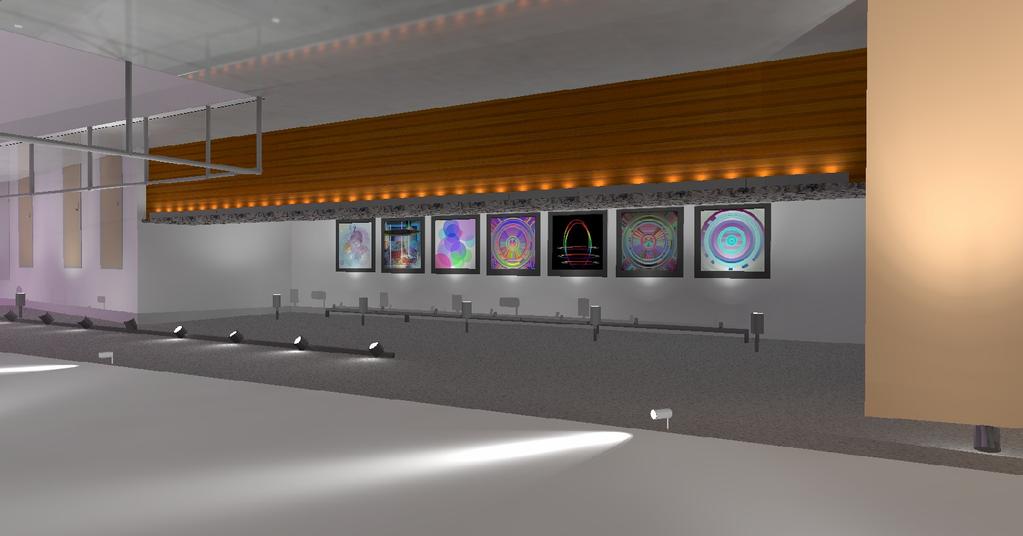
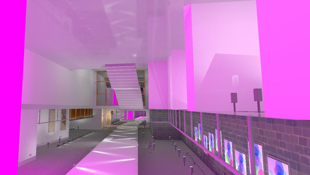
10 Lobby Space Overview As patrons enter the lobby, they are in for a huge surprise. The theater is said to get lost in the cityscape; but once you are inside everything becomes clear. Entering from street level, patrons come in on the second floor. The lobby has a tunnel like feel, extending 130 back and varying widths between The finishes are unfinished, looking industrial and edgy. There are only a few key colors in the space. On this level there are a ticket booth and café. There is a long balcony, referred to as the lobby catwalk, descending the entire length of the space where seating is available and art is on display. Also extending the length of the space is a white gypsum board ceiling panel. This helps to draw the eye to the back of the space. Moving further into the space, stairs will take patrons down to the first level where the lobby is a double-heighted space. The stairs and bridges are cleverly placed to invite movement between the first and second levels of the lobby. On this level there are seating areas, a book stall, a café and the entrances to the orchestra seating. When inside the space, there is no mistake where the theater is. A 22 high curved polycarbonate wall stands between the lobby and theater. This semi-translucent wall has a layer of mylar behind it. 10
11 Materials in the Space concrete slab ceiling- clear finish reflectance = 20% white painted gypsum wall board ceiling panel reflectance = 90% concrete slab floor- clear satin finish reflectance = 35% masonry block walls- clear finish reflectance = 25% white painted gypsum walls reflectance = 95% polycarbonate translucent wall- ice color wood paneling on ticket booth and both café fronts plastic laminate counter tops blue painted gypsum walls around ticket booth reflectance = 65% orange painted gypsum wall at entry seating area reflectance = 65% Glazing 2 sided glazing system with vertical joints ½ thick clear laminated glazing Multi-walled structured polycarbonate glazing Polygal: translucent extruded polycarbonate sheet with internal ribbing and smooth flat exterior surface, Color Ice Daylighting Above the two story high lightwall, the curve continues with glass. This curved third story glass wall (wall to the office suite) faces an exterior glass façade wall, with a gap of three to eight feet. This gap is open to the lobby space. This technique provides daylight to shine through the third story glass façade and down into the lobby during the daytime. A daylight study was not performed because all of the direct sunlight entering the lobby space hits the light wall. The daylighting does provide ambient light for the daytime, and therefore the theatre company can dim the lighting during those hours. Design Criteria General In this lobby many tasks will be taking place. Tickets, programs and souvenirs will be bought; and snacks will be eaten. The lobby will provide a space for patrons to wait before and after performances. Glare should be completely avoided. Color rendering and facial modeling are all very important in the lobby. Patrons will be spending time in this space and should look beautiful. There should be points of visual interest and sparkle in the room. This will lead the eye through the space and keep patrons interested. Illuminance and Luminance Values According to the IESNA, between 15 and 20 footcandles of horizontal illuminance is desirable for lobbies and foyers in theaters of live productions. The artwork and posters in the space should range from 70 to 350 cd/m^2, depending on surrounding brightness. 11


12 Power Density According to Ashrea 90.1 (2004), using the space by space method for a lobby of a performing arts building, 3.3 W/SF are allowed. Schematic Design/Design Intent Design Goals Color Sparkle Rhythmic - Invites Movement and Flow Most Exciting Space The lobby of the Woolly Mammoth Theatre will be the first interior space patrons will see. The appearance should be pleasing to the eye, feeling inviting and exhilarating. Its edgy design will draw people into the space. Because the majority of the finishes are white and unfinished concrete, colored light will help the space come alive. This light will spread throughout the space giving the lobby a glow of color. The lobby s main character comes from its architecture: the way the stairs are placed, the balconies over looking the lower floor, the small nooks and book stalls, and the gypsum panel extending into the space. These architectural features will be highlighted and be made to sparkle wherever possible. The architecture also lends itself to movement, and therefore the lighting will keep with that theme. The lighting should be very rhythmic, which will encourage flow and movement. The space will have brightness patterns that attract the eye, as well as influence flow through the space. There should be many layers of light throughout the space, with visual clues as to where to go. This will guide patrons through the tunnel-like dimensions. This space will be the height of experience for the theatre, until the patrons actually see the performance in the theatre. Concept Photos 12

13 Concept Diagram 13
14 Final Design Second Floor (Street Level) Lighting Plan 14
15 First Floor Lighting Plan 15

16 Fixture, lamp and ballast cut-sheets can be found in Appendix A. 16
17 Light Loss Factors Fixture Cleaning Interval Category BF LLD LDD RSDD LLF 12 months A1 (clean) IV A2 12 months (clean) IV A3 12 months (clean) IV A4 12 months (clean) IV A5 12 months (clean) IV A6 12 months (clean) IV A7 12 months (clean) IV RCR Calculated to be 3.1 Space Assumed to be Very Clean The cleaning interval for the lobby was assumed to be 12 months since the building is owned and maintained by the theatre company directly. The space was assumed to be a clean environment because there are no surrounding spaces where adhesive or ambient dirt would be generated. Power Density Fixture Quantity Wattage Total Wattage SF W/SF A A A A A A A Using the input wattages for the specified ballast and lamps, the power density for the lobby is 1.49 W/SF. This is significantly under the 3.3 W/SF allowed for the lobby of a performing arts building. 17
18 Calculation Grids 18


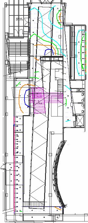
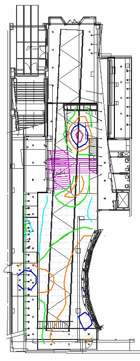
19 The average illuminance of the second floor (street level) of the lobby is 15 fc, with a maximum of 28 fc and a minimum of 5 fc. The area with the lowest light levels, about 10 fc, is directly near the entrance. This is acceptable because the entrance wall and front façade are both glass. Therefore during the day, daylight will illuminate this area. During the evening, the canopy lighting will illuminate this area. The balcony catwalk has an even distribution of 17 fc. The second floor should be slightly dimmer than the first, because there should be more contrast with the accenting of the art and gypsum panel. The first floor illuminance is slightly higher than the second floor, having an average of 17 fc. Having the first floor illuminance level higher will encourage patrons too look up at the gypsum panel and art running through the space. The catwalk are has an average of 30 fc, with a very even distribution of 1.79 average to minimum fc. This is important because the art of the catwalk is not constant. The even distribution will let the theatre company place any type or size art display on the wall. The ticket booth art has a lower illuminance average of 15 fc, because the ticket booth floor has a lower illuminance than the catwalk floor. The art lighting is not completely evenly distributed. There are seven permanent pictures hanging on the wall, each fixture is accent one picture. These pictures are never removed, and therefore each one can be highlighted more dramatically. 19
20 Control The lobby lighting will be on a standard theatrical dimming rack controlled by an architectural interface. The lobby lighting will be zoned according to type of fixture and area of the room. All lobby fixtures will be controlled by this system. The accent fixtures lighting the gypsum ceiling panel will be on a chase sequence (first fixture will fade to a higher level, then second, then third and so on). The sequence will run slow, being subtle. This will make the space have a dynamic feel and will guide patrons into the tunnel like room. The LED floodlights lighting the polycarbonate wall will be color changing, so they can be set on one color, or a color changing sequence. When they are color changing, the sequence will be very slow, so it does not compete with the accents on the gypsum panel. The lobby will have many different lighting scenes for different circumstances. Four typical preset scenes useful to the theatre company would be night performance, day performance, day ambient and night ambient. These presets could also be altered for specific needs of the event as well. 20
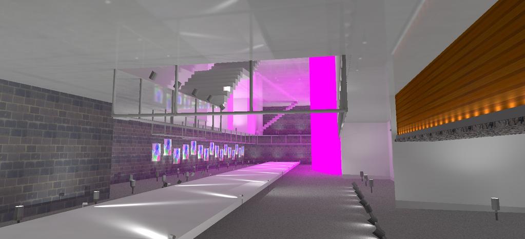
21 Renderings 21
22 Conclusion The lobby is an architecturally complex space. The lighting design must work with the architecture to enhance the space. The suspended gypsum panel is one of the most important features in the lobby. The accent lighting on the stark white panel will guide patrons into the space. Once led to the back of the lobby, patrons will see the 22 high lightwall. The panel and this wall are completely contrasting, adding dimension to the space. The panel is white, long and narrow, straight, and unevenly lit with accents. The light wall is robust, colored, curved and evenly distributed. These two elements are very prominent and define the space. The track used throughout the space highlights many unique features of the architecture including stairways, walls, balconies and artwork. The orange accent wall and the wood paneling on the ticket booth were lit to draw attention to their color and texture. The new design for the lobby is aesthetically pleasing, as well as fulfills the design criteria and its purpose. The lobby is a very exciting space, and with the new lighting design the space comes alive. 22


23 Lobby Design 2 In the second design for the lobby, the track fixtures accenting the catwalk and the ticket book art were changed from 50 W MR16 fixtures to 35 W LED fixtures. The LED fixture is fixture type A8. The fixture cut-sheet can be found in Appendix A. The design will be critiqued on performance and cost/efficiency. Performance The average illuminance on both the catwalk art and the ticket booth art is only about 1 fc to 2 fc higher using the LED fixture. This is because the LED fixture s rated lumens are 100 lumens more that the MR16 fixture. Due to this fact, the LED fixture could actually be compared with a 71 W MR16. The LED fixture provides a very even distribution on the catwalk art, and a diverse distribution on the ticket booth art, just as the MR16 fixture does. The LED fixture has 100% lumen maintenance, whereas the MR16 only has 90%. The CCT and CRI of both fixtures are equivalent. 23
24 Efficiency and Cost The rated lamp life for the LEDs is 50,000 hours. This is much longer than the lamp life of 6,000 hours for the MR16. The wattage of the LED fixture is also less, 35W compared to the 50 W for the MR16. Below is a calculation of the money saved on electricity with the new design, using the LED track versus the MR16 track. According to this energy analysis, every LED fixture saves about $6.00 per year. For the lobby design there are 29 fixtures. This would give a total savings of $174 per year. This does not take into account the initial cost of the fixture (at least $200 more than the MR 16 fixture). 24
25 In the calculation below, the initial cost of the LED fixture is taken into account, and a payback is generated for the new system. In this calculation, the efficiency of the fixture does not outweigh the extra cost. A payback of 67 years is too long of a payback. If there were more fixtures being replaced in the space, or if the MR16 fixtures were using 71 W lamps, the benefits would have been greater. Conclusion LEDs are the newest technology in lighting design. They are getting better and better every day, with more options for fixtures, brighter lamps and better dimming solutions. Yet they are not the best solution in every case. In this design, the LEDs would save a small amount of money on electricity, but the payback of the initial cost is probably longer than the system will even be installed. Therefore the LEDs should not be used. The reliable, cheap and versatile MR16 should be kept for the track lighting of the catwalk and ticket booth artwork. 25


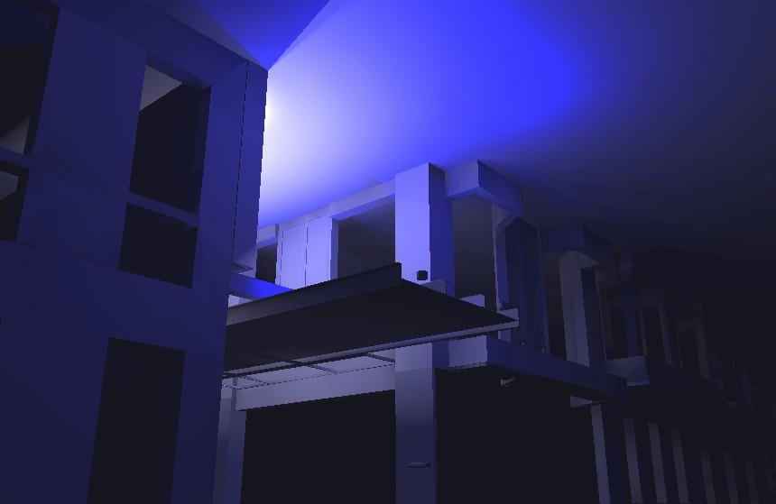
26 Canopy Space Overview The Woolly Mammoth Theatre sits on a busy street in downtown DC. It has a historic brick façade facing this street and remains very low-key. The doors to this storefront remain closed. To enter the theatre, patrons must go around the corner. The alley does have a canopy to make it more apparent. The canopy is made of black steel columns/beams and a plastic glazing panel. There is also an area to hang advertisements for upcoming shows. Yet this canopy is not glitzy or glamorous. It has an industrial feel, which will prevail throughout the space. The canopy will direct patrons to the entrance of the theatre. The appearance of the luminaires will foreshadow what will be seen throughout the building. There should be accent lighting on the wall of the adjacent building where posters are being displayed. This area should have sparkle and be eye-catching. The steel and glass surfaces should appear to be beautiful. The majority of the theatre company s shows are in the evening hours. The theater should blend in to the cityscape during the work day. Once it becomes dusk, the full view of the theatre should become apparent from the outside. 26
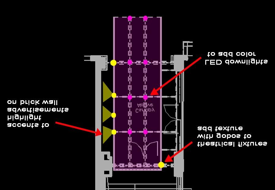
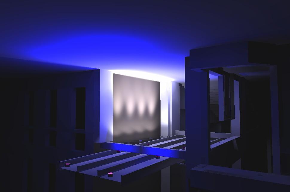
27 Materials in the space black steel structure reflectance = 20% brick walkway reflectance = 35% brick and glass façade of theatre on one side brick adjacent building facade Glazing polycarbonate panel Polygal: translucent extruded polycarbonate sheet with internal ribbing and smooth flat exterior surface, Color Ice Horizontal Illuminance According to IESNA Handbook there should be 5 footcandles of horizontal illuminance on the ground. There should also be at least 3 footcandles of vertical illuminance. Power Density According to the ASHREA 90.1 (2004), using the Space- By- Space method, the power density allowed for an entrance canopy is 1.25 W/SF. Schematic Design/Design Intent Design Goals Eye-catching Peeks Interest Depth Foreshadow What Is Inside The entrance to the Woolly Mammoth Theatre is located in an alleyway. To make the canopy eye-catching during hours of operation, color and texture were used. The RGB LED downlights will be able to be a variety of colors. This will peek the interest of onlookers. They will want to know what is inside the building. The two theatrical fixtures will be very close to white light. They will have gobos to add texture to the canopy floor. The layering of light will give the space depth. All of these features will foreshadow the color and texture to be seen once entering the building. 27


28 Concept Photos Concept Diagram 28
29 Final Design Lighting Plan 29

30 All fixture, lamp and ballast cut-sheets can be found in Appendix A. 30
31 Light Loss Factors Fixture Cleaning Interval Category BF LLD LDD RSDD LLF EX1 EX2 12 months (medium) IV months (medium) IV EX3 12 months (medium) IV RCR Calculated to be 5.6 Space Assumed to be Clean The cleaning interval for the canopy was assumed to be 12 months since the building is owned and maintained by the theatre company directly. The space was assumed to be a medium environment. The canopy is an exterior space, but is in between two large buildings in an alley. Therefore the amount of dirt would generated is not high. Power Density Fixture Quantity Wattage Total Wattage SF W/SF EX EX EX Using the input wattages for the specified ballast and lamps, the power density for the canopy is 1.87 W/SF. This is slightly over the allowed 1.25 W/SF. Taking into account the power allowances of the other redesigned spaces, all of which were significantly under the allowed power density, the canopy being over is acceptable. Fixture type EX3 is an exception in the power density calculation because it is an integral part of advertising. 31

32 Calculation Grids The average illuminance of the canopy floor is 6 fc, which fulfills the suggested value of 5 fc. The lighting is evenly distributed over the canopy floor with a average to minimum fc ratio of This is ideal because the colored light should be as even as possible to give the canopy space a glowing feel. The theatrical fixtures with gobos were not taken into account in this calculation. They will add light to the space, but will be used strictly for texture. 32

33 Advertisements on Brick Facade The aiming of the accents on the brick façade is adjustable, and can be changed with the size of the advertisement. In this calculation the accents were arbitrarily aimed as if there were two advertisements. This façade has significantly more illuminance than the canopy area itself. This will direct the patron s attention to the advertisement. Control The canopy lighting will be controlled by the same system as the lobby. This will allow the LED fixtures to be color changing on a sequence. Also the accents for the advertisements and the theatrical fixtures can be dimmed. The exterior zones will not be on during the day, unless it is a very dark day. If necessary the advertisement lighting can be used to add light to the space during daytime hours. All the exterior fixtures will be turned on at dusk. 33
34 Renderings 34
35 Conclusions The canopy of the Woolly Mammoth Theatre is located in an alley off of the main road. This adds to the mystery of the theatre, because it is almost lost in the cityscape. During the day the theatre will blend in with the surrounding buildings, but at night the space will come alive. The lighting design for the canopy is edgy, using high-tech fixtures and control. Color and texture are used to grab the attention of outsiders. The space shows people a glimpse of what can be seen inside the building. The new design for this space fulfills the design criteria as well as embraces the lighting design concept. 35


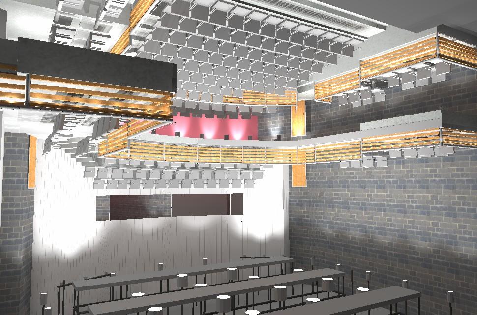
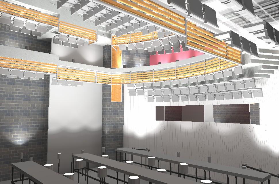
36 Theatre Space Overview Entering the theatre through the main entrance on the orchestra floor, there is no grand entrance. The doors are awkwardly placed behind a concrete column. The theme of the theatre is to be intimate and edgy. It is a 6,000 SF space with seating on two levels, 187 orchestra and 78 balcony plus standing room. The theatre has a courtyard configuration designed to connect the audience and actors in this cozy setting. The space is high and deep, making it very flexible. The main finish throughout the theatre is black. The only color in the space is the maple seat backs, the wood slats on the balcony fronts and the red accent wall at the back of the theatre. 36
37 Materials in the Space concrete slab ceiling- clear finish reflectance = 20% concrete block walls- clear finish reflectance = 20% concrete block walls- black stained finish reflectance = 10% concrete wall- clear finish reflectance = 20% concrete wall- black stained finish reflectance = 10% red painted gypsum wall reflectance = 30% concrete slab floor- clear satin finish reflectance = 30% carpet- dark gray reflectance = 10% light wood paneling on balcony fronts black upholstered seats black metal catwalks metal railings Design Criteria General Before and after a performance, the theatre house lighting will be on. This lighting should be diffuse and comfortable. In this time patrons will be entering and exiting the theatre, finding their seats, reading programs and waiting for the performance to begin. The lighting should have some accenting or visual interest, as patrons may be waiting lengths of time in their seats. The space should appear to be at a high quality in appearance. Color rendering and facial modeling are very important to achieve this. The general lighting should be on dimming control. Also panic switches independent of dimmers and switches should be provided to bring on selected house lights in case of an emergency. Emergency house lighting, exit lighting, and aisle lighting are all necessary. Illuminance and Luminance Values A minimum of 10 to 20 footcandles should be maintained throughout the seating area when a performance is not taking place. Higher illuminances of 30 footcandles are required to perform visual tasks, such as rehearsals, cleaning and maintenance of the space. During performances emergency light levels must be 0.2 footcandles. Power Density According to Ashrea 90.1 the power density for an audience/seating area in a performance space is 1.8 watts/sq. ft. 37


38 Schematic Design/Design Intent Intimate Subdued Sparkle The lighting for the theatre must come alive in a different way than the previously discussed spaces. The main function of the theatre is to hold the performance. For that reason the lighting before and after the show should not compete with the show itself. The house lighting should prepare the audience for the production. Staying with the architectural concept of the theatre, the lighting should enhance the intimate feeling of the theatre. Sparkle should be added to the space. This will be accomplished by expressing the equipment and the actual theatre mechanics to enhance the space and add sparkle. The lighting of the theatre will be subtle, yet still make the space come alive. Concept Photos 38

39 Concept Diagram 39
40 Final Design Orchestra Level Lighting Plan 40
41 Orchestra Level Lighting RCP 41
42 Balcony Plan 42
43 Balcony Level RCP 43

44 All fixture, lamp and ballast cut-sheets can be found in Appendix A. 44
45 Light Loss Factors Fixture Cleaning Interval Category BF LLD LDD RSDD LLF C1 12 months (clean) IV C2 12 months (clean) IV C3 12 months (clean) IV C4 12 months (clean) IV C5 12 months (clean) IV C6 12 months (clean) IV C7 12 months (clean) IV RCR Calculated to be 4.1 Space Assumed to be Very Clean The cleaning interval for the lobby was assumed to be 12 months since the building is owned and maintained by the theatre company directly. The space was assumed to be a clean environment because there are no surrounding spaces where adhesive or ambient dirt would be generated. Power Density Fixture Quantity Wattage Total Wattage SF W/SF C C C C C C C Using the input wattages for the specified ballast and lamps, the power density for the lobby is 1.03 W/SF. This is under the 1.8 W/SF allowed for audience seating areas of a performing arts building. 45


46 Calculation Grids Orchestra Level Ambient Lighting The average illuminance on the orchestra level floor is between 25 and 30 fc in the seating areas. The entrance areas have an average illumination of 17 fc. These illumination levels satisfy the design criteria requirements. Before and after performances, the lighting will be dimmed to an average of 10 to 15 fc. The lighting will be on 100% when cleaning the theatre, and during rehearsals. The orchestra level has a very diffuse illumination across the space. The largest average to minimum fc ratio is 3.71, which is still an even distribution to the eye. This calculation did not take into account accent lighting. 46


47 Balcony Level Ambient Lighting The average illuminance on the balcony level floor is between 23 and 26 fc. These illumination levels satisfy the design criteria requirements. Before and after performances, the lighting will be dimmed to an average of 10 to 15 fc. The lighting will be on 100% when cleaning the theatre, and during rehearsals. The balcony level has a very diffuse illumination across the space. The largest average to minimum fc ratio is 3.84, which is still an even distribution to the eye. This calculation did not take into account accent lighting. Therefore the average illumination of Row C will be higher. 47


48 Aisle: Step lighting The step lights in the aisle will be on during performances. They provide the necessary 0.2 fc illumination for emergency lighting. Balcony Level: Back Wall Metal Acoustical Baffles The back wall of the balcony level is metal acoustical baffle. The finish has a high quality look, and therefore is accented with track. This adds layering of light to the space, which add depth. The wall has an uneven distribution to keep with the concept of intimate. The track fixtures are on the theatrical control system and can be dimmed. 48


49 Orchestra Level: Back Red Wall The back wall of the orchestra level is a red painted gypsum board wall. Track is run along the wall to add small scallops of light. The track is spaced far enough apart so the wall is not uniformly lit. This accenting adds subtle visual interest and sparkle to the space. The track also gives an intimate feeling to the space. 49
50 Renderings 50
51 Conclusion The theatre s architecture lends itself to an intimate atmosphere. The courtyard configuration establishes a strong connection with the audience and actors. The lighting of the theatre must not disrupt that connection. The lighting must also be subtle, so it does not compete with the production. In keeping with these goals, the theatre comes alive in a different way than the lobby and canopy. A low level of diffuse ambient light is provided for circulation needs. Track is used to accent the back walls of the orchestra and balcony levels, which both have finishes that are high quality and add visual interest. The metal acoustical baffles, when accented, add sparkle by highlighting the theatre mechanics. The wood panels on the fronts of the balconies are lit with a LED railing light, accenting the beautiful wood finish and bringing the focus away from the outer walls. This also keeps the space intimate. The lighting design parallels with the architectural concept of the theatre space, therefore enhancing the theatre environment. 51


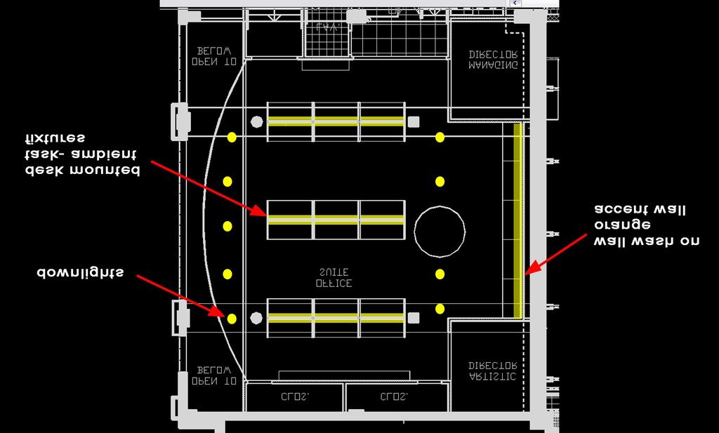
52 Office Space Overview The office has an open plan with two private offices for the artistic director and the managing director. There are movable cubicles set up in three sections. It is a comfortable environment for the key personnel of the theatre to do work. The space is rather small but has a spacious feel. This was achieved by using glass for the surrounding interior walls connecting the office to the vestibule, hub area and exterior. Material in the Space concrete slab ceiling- clear finish reflectance = 20% orange painted gypsum walls reflectance = 55% carpet- medium gray reflectance = 25% cubicle partitions- light reflectance = 60% Glazing ½ tempered glass transmittance = 80% 3/8 clear laminated glazing faceted wall transmittance = 80% 52
53 Daylighting Study A daylighting study was conducted for the days of June 21, December 21 and March 21. These three dates are when the sky is at its highest point, its lowest point, and in the middle. The office has a full glazed wall facing west. The curved wall is 3/8 thick clear laminated glazing faceted wall. This wall is adjacent to another glass wall. The straight wall is ½ thick tempered glass. The office also has one diffuse skylight dome in the other half of the office area. This dome provides ambient lighting to the office with no direct sunlight entering the space. The daylighting analysis was studied for two criteria, direct light hitting the work plane and ambient light levels. It is very important direct daylight does not hit the task surface in the office space. This will cause poor visibility and discomfort. Yet direct sun when used cautiously, where non-critical task occur can be a good design feature. Patterns of light and shadows from the sun add a dynamic feature to the space. They give the occupants a sense of well-being, time and orientation. 53


54 Direct Glare March 21 3:00 PM March 21 5:00 PM 54

55 June 21 3:00 PM June 21 5:00 PM 55
56 December 21 1:00 PM December 21 3:00 PM 56
57 As seen in the previous renderings, direct glare is not a major problem in the office suite. The furniture layout of the cubicles was well thought out. The walls of the cubicles closest to the glazing block the direct glare most of the time. The few instances that the direct sunlight does hit the task surface, it did not cover much area. The direct sunlight did add a dynamic effect to the office suite, adding patterns and shadows from the mullions. The daylight in the office suite provided a large amount of ambient light to the space. The problem is the light provided is not evenly distributed. The desks closest to the window receive daylight in most conditions. The daylight does not reach far into the space during most months out of the year. The skylight provides low levels of diffuse light to the space. Conclusion With the current furniture layout, direct glare is not a problem in the office suite. The direct sunlight does add a dynamic aspect to the space. Therefore the glazing does not need to be altered from the current glazing, clear with 80% transmittance. Daylight does provide a sufficient amount of light into the office suite. Yet the majority of the light is not evenly distributed over the task surface. Also only the cubicles closest to the glazing have enough illumination. It would be possible to specify a dimming system for this office suite, but it was not necessary for the space. When personal cubicles are universally controlled and dimmed, many people are unhappy. After speaking with the employees of the Woolly Mammoth Theatre Company, they did not want to install a dimming system. They workers wanted a very bright work environment. Therefore the office suite is not dimmed. 57
58 Design Criteria General The lighting in the office should be very comfortable. The work surfaces should be uniformly lit. In the office there is intermittent use of VDTs. Direct and reflected glare should be avoided completely. It is important to avoid having direct sunlight hit the work surface, creating glare. Also the luminances of surfaces and contrast must be carefully analyzed. The open plan office has moveable cubicles, and therefore the lighting should be flexible. Illuminance and Luminance Values According to the IESNA Lighting Handbook the illuminance on the work plane for an open office with intense VDT work should be 30 footcandles. The vertical illuminance should be 5 footcandles. When using VDTs, the luminance ratio of screen to paper task should be 3:1. For screen to far background the luminance ratio should be 10:1. Power Density According to Ashrea 90.1, the Space- By- Space Method, the power density allowed in an open plan office is 1.1 W/SF. Schematic Design/ Design Intent Design Goals Spacious Comfortable Energetic These goals were achieved in the office space by using many techniques. The office is small in square footage, and rather cramped with cubicles throughout it. Two of the four walls are made of glass, which helps to expand the feeling of the space. In the lighting of the space, the orange accent wall is washed with light. This will keep the space feeling spacious. To keep the office comfortable for the employees, direct and reflected glare must be avoided completely. This was accomplished by using a desk mounted fixture with direct and indirect light. The energetic feeling was achieved by using indirect light to stop the cave effect. Also there are differing light levels away from task areas to give depth. 58


59 Concept Photos Concept Diagram 59
60 Final Design Lighting Plan 60
61 Luminaire Detail Fixture Type F1 task- ambient fixtures will are plug in fixtures. They will receive power from the floor mounted receptacles showed in red. 61

62 Fixture, lamp and ballast cut-sheets can be found in Appendix A. 62
63 Light Loss Factors Fixture Cleaning Interval Category BF LLD LDD RSDD LLF F1 12 months (clean) II F2 12 months (clean) IV F3 12 months (clean) IV F4 12 months (clean) IV F5 12 months (clean) IV F6 12 months (clean) IV F7 12 months (clean) IV RCR Calculated to be 2.2 Space Assumed to be Very Clean The cleaning interval for the office suite was assumed to be 12 months since the building is owned and maintained by the theatre company. The space was assumed to be a clean environment. The office suite is small area on the third floor on the theatre. It is not near any spaces that would generate large amounts of dirt. Power Density Fixture Quantity Wattage Total Wattage SF W/SF F F F F F F F Using the input wattages for the specified ballast and lamps, the power density for the lobby is 0.84 W/SF. This is under the allowed 1.1 W/SF allowed for an open office. 63


64 Calculation Grids The average illuminance of the work plane is 16 fc. This is an ideal level for the areas that are not work surfaces. The average to minimum fc ratio is 6.7. The office having slightly different levels of light in the space will make the space comfortable and add visual interest for the employees. Due to the task component of the task-ambient fixtures on each cubicle, the average cubicle illuminance is 33 fc, very evenly distributed with a 2.30 average to minimum fc ratio. The ambient component of the task-ambient fixtures used will illuminate the ceiling, to make the space feel energetic and not like a cave. The fixtures also eliminate direct and reflected glare because the source is mounted on each cubicle. Another advantage of the task-ambient fixtures is they are mounted to the cubicles, and therefore can move with the cubicle if the office is rearranged or more cubicles are added. 64
65 Orange Accent Wall The orange accent wall has an average illuminance of 18 fc, with an average to minimum fc ratio of The wall is evenly distributed, giving the office a spacious feel while highlighting the spectacular color of the wall. Control The office suite will be standard switched control. Dimming of the design was unnecessary. The zones of fixtures are switched separately, giving the office suite some control. During most days the recessed downlights adjacent to the glass wall will not need to be on. The cylinders near the skylight will also not be needed on a number of days. All of the cubicle lights will be switched together. This is because if they are separately switched, the ambient component of light would be a very uneven distribution on the ceiling, having some lights on and some off. Also, after speaking with employees in the space office, they all agreed they would like a very bright environment. This environment will be an energetic space that leads to productivity. 65
66 Renderings 66
67 Conclusion The office suite is a private space for the employees at the Woolly Mammoth Theatre. The workers spend long hours each week performing their duties in the space. Due to this, the lighting must be designed for comfort. The office should feel spacious and energetic, to encourage production in the space. All employees in the office suite use VDTs. The task-ambient light used in the design eliminates reflected and direct glare from the ceiling. This fixture also makes the design flexible with the movable cubicles. The task component provides the necessary illumination on the work surface, and the ambient component provides illumination on the ceiling to brighten the space. The wall washers accent the vibrant orange wall and give an energetic feel to the space. The office suite is controlled by standard switching, but zoned with the ability to switch areas off separately. The lighting design for the office is feasible, and 67
68 El ect r ical Dept h 68
69 Electrical Depth Electrical and Control Plans Canopy 69
70 Lobby Second Floor (Street Level) Plan 70
71 First Floor Plan 71
72 Theatre Orchestra Level Plan Orchestra Level RCP 72
73 Balcony Level Plan Balcony Level RCP 73
74 Office 74
75 Panelboards Existing Panel M3 P A N E L B O A R D S C H E D U L E VOLTAGE: 208Y/120V,3PH,4W SIZE/TYPE BUS: 225A SIZE/TYPE MAIN: 225A/3P C/B PANEL TAG: M3 PANEL LOCATION: xx PANEL MOUNTING: SURFACE MIN. C/B AIC: 85K OPTIONS: DESCRIPTION LOCATION LOAD (WATTS) C/B SIZE POS. NO. A B C POS. NO. C/B SIZE LOAD (WATTS) LOCATION DESCRIPTION RECEPTACLE A/1P 1 * 2 20A/1P 1000 AHU-5 RECEPTACLE A/1P 3 * 4 20A/1P 1000 AHU-5 RECEPTACLE A/1P 5 * 6 20A/1P 1000 AHU-5 RECEPTACLE A/1P 7 * 8 20A/1P 1000 REFRIGERATOR RECEPTACLE A/1P 9 * 10 20A/1P 400 ICEMAKER RECEPTACLE A/1P 11 * 12 20A/1P 475 LIGHTS RECEPTACLE A/1P 13 * 14 20A/1P 400 TRACK LIGHTS RECEPTACLE A/1P 15 * 16 20A/1P 300 TRACK LIGHTS RECEPTACLE A/1P 17 * 18 20A/1P 190 LIGHTS RECEPTACLE A/1P 19 * 20 20A/1P 400 TRACK LIGHTS DISPLAY LIGHTS A/1P 21 * 22 20A/1P 190 LIGHTS RECEPTACLE A/1P 23 * 24 20A/1P 600 SUMP PUMP RECEPTACLE A/1P 25 * 26 20A/1P 0 SPARE RECEPTACLE A/1P 27 * 28 20A/1P 0 SPARE RECEPTACLE A/1P 29 * 30 20A/1P 1000 BASEBOARD HEATER RECEPTACLE A/1P 31 * 32 20A/1P 1000 BASEBOARD HEATER SPARE 0 20A/1P 33 * 34 20A/1P 1000 BASEBOARD HEATER SPARE 0 20A/1P 35 * 36 20A/1P 1000 BASEBOARD HEATER SPARE 0 20A/1P 37 * 38 20A/1P 1000 BASEBOARD HEATER SPARE 0 20A/1P 39 * 40 20A/1P 1000 BASEBOARD HEATER SPARE 0 20A/1P 41 * 42 20A/1P 1000 BASEBOARD HEATER CONNECTED LOAD (KW) - A 6.56 TOTAL DESIGN LOAD (KW) CONNECTED LOAD (KW) - B 5.63 POWER FACTOR 0.95 CONNECTED LOAD (KW) - C 7.03 TOTAL DESIGN LOAD (AMPS) 61 New Panel M3 P A N E L B O A R D S C H E D U L E VOLTAGE: 208Y/120V,3PH,4W SIZE/TYPE BUS: 225A SIZE/TYPE MAIN: 225A/3P C/B PANEL TAG: M3 PANEL LOCATION: xx PANEL MOUNTING: SURFACE MIN. C/B AIC: 85K OPTIONS: DESCRIPTION LOCATION LOAD (WATTS) C/B SIZE POS. NO. A B C POS. NO. C/B SIZE LOAD (WATTS) LOCATION DESCRIPTION RECEPTACLE A/1P 1 * 2 20A/1P 1000 AHU-5 RECEPTACLE A/1P 3 * 4 20A/1P 1000 AHU-5 RECEPTACLE A/1P 5 * 6 20A/1P 1000 AHU-5 RECEPTACLE A/1P 7 * 8 20A/1P 1000 REFRIGERATOR RECEPTACLE A/1P 9 * 10 20A/1P 400 ICEMAKER RECEPTACLE A/1P 11 * 12 20A/1P 0 SPARE RECEPTACLE A/1P 13 * 14 20A/1P 0 SPARE RECEPTACLE A/1P 15 * 16 20A/1P 0 SPARE RECEPTACLE A/1P 17 * 18 20A/1P 0 SPARE RECEPTACLE A/1P 19 * 20 20A/1P 400 TRACK LIGHTS SPARE 0 20A/1P 21 * 22 20A/1P 190 LIGHTS RECEPTACLE A/1P 23 * 24 20A/1P 600 SUMP PUMP RECEPTACLE A/1P 25 * 26 20A/1P 0 SPARE RECEPTACLE A/1P 27 * 28 20A/1P 0 SPARE RECEPTACLE A/1P 29 * 30 20A/1P 1000 BASEBOARD HEATER RECEPTACLE A/1P 31 * 32 20A/1P 1000 BASEBOARD HEATER SPARE 0 20A/1P 33 * 34 20A/1P 1000 BASEBOARD HEATER SPARE 0 20A/1P 35 * 36 20A/1P 1000 BASEBOARD HEATER SPARE 0 20A/1P 37 * 38 20A/1P 1000 BASEBOARD HEATER SPARE 0 20A/1P 39 * 40 20A/1P 1000 BASEBOARD HEATER SPARE 0 20A/1P 41 * 42 20A/1P 1000 BASEBOARD HEATER CONNECTED LOAD (KW) - A 6.16 TOTAL DESIGN LOAD (KW) CONNECTED LOAD (KW) - B 5.03 POWER FACTOR 0.95 CONNECTED LOAD (KW) - C 6.36 TOTAL DESIGN LOAD (AMPS) 56 75
76 Panel M3 Sizing Note: All wires to be sized 75 degrees C, THWN, CU wire Design Load: 56 Amps Circuit Breaker Size: 60 Amps Feeder Size: #8 AWG Neutral: #8 AWG Ground: #10 AWG Conduit Size: 1 inch 76
77 Existing Panel L5 P A N E L B O A R D S C H E D U L E VOLTAGE: 208Y/120V,3PH,4W PANEL TAG: L5 SECTION A MIN. C/B AIC: 85K SIZE/TYPE BUS: 225A PANEL LOCATION: xx OPTIONS: DOUBLE SECTION PANEL WITH SIZE/TYPE MAIN: 225A/3P C/B PANEL MOUNTING: RECESSED CABLE TIES BETWEEN MAIN LUGS DESCRIPTION LOCATION LOAD (WATTS) C/B SIZE POS. NO. A B C POS. NO. C/B SIZE LOAD (WATTS) LOCATION DESCRIPTION RECEPTACLE A/1P 1 * 2 20A/1P WH-1 RECEPTACLE A/1P 3 * 4 20A/1P WH-1 RECEPTACLE A/1P 5 * 6 20A/1P WH-1 RECEPTACLE A/1P 7 * 8 20A/1P LIFT RECEPTACLE A/1P 9 * 10 20A/1P RECEPTACLE RECEPTACLE A/1P 11 * 12 20A/1P LIGHTS RECEPTACLE A/1P 13 * 14 20A/1P 0 0 SPARE RECEPTACLE A/1P 15 * 16 20A/1P TRACK LIGHTS RECEPTACLE A/1P 17 * 18 20A/1P TRACK LIGHTS RECEPTACLE A/1P 19 * 20 20A/1P TRACK LIGHTS RECEPTACLE A/1P 21 * 22 20A/1P 0 0 SPARE RECEPTACLE A/1P 23 * 24 20A/1P 0 0 SPARE RECEPTACLE A/1P 25 * 26 20A/1P RECEPTACLE RECEPTACLE A/1P 27 * 28 20A/1P RECEPTACLE RECEPTACLE A/1P 29 * 30 20A/1P RECEPTACLE RECEPTACLE A/1P 31 * 32 20A/1P CARD READER RECEPTACLE A/1P 33 * 34 20A/1P PROCESSOR PANEL REFRIGERATOR A/1P 35 * 36 20A/1P 0 0 SPARE REFRIGERATOR A/1P 37 * 38 20A/1P 0 0 SPARE RECEPTACLE A/1P 39 * 40 20A/1P 0 0 SPARE COUNTER LIGHTS A/1P 41 * 42 20A/1P 0 0 SPARE CONNECTED LOAD (KW) - A 6.69 TOTAL DESIGN LOAD (KW) CONNECTED LOAD (KW) - B 5.91 POWER FACTOR 0.90 CONNECTED LOAD (KW) - C 4.35 TOTAL DESIGN LOAD (AMPS) 54 P A N E L B O A R D S C H E D U L E VOLTAGE: 208Y/120V,3PH,4W PANEL TAG: L5 SECTION B MIN. C/B AIC: 85K SIZE/TYPE BUS: 225A PANEL LOCATION: xx OPTIONS: DOUBLE SECTION PANEL WITH SIZE/TYPE MAIN: 225A/3P C/B PANEL MOUNTING: RECESSED CABLE TIES BETWEEN MAIN LUGS DESCRIPTION LOCATION LOAD (WATTS) C/B SIZE POS. NO. A B C POS. NO. C/B SIZE LOAD (WATTS) LOCATION DESCRIPTION TRACK UP A/1P 43 * 44 20A/1P PERF. LTS TRACK UP A/1P 45 * 46 20A/1P PERF. LTS TRACK UP A/1P 47 * 48 20A/1P TRACK TRACK DOWN A/1P 49 * 50 20A/1P LIGHT-WALL TRACK DOWN A/1P 51 * 52 20A/1P LIGHT-WALL TRACK DOWN A/1P 53 * 54 20A/1P LIGHT-WALL TRACK A/1P 55 * 56 20A/1P 800 LIGHT-WALL TRACK A/1P 57 * 58 20A/1P LIGHT-WALL SPARE A/1P 59 * 60 20A/1P LIGHT-WALL SPARE A/1P 61 * 62 20A/1P 0 0 SPARE SPARE A/1P 63 * 64 20A/1P 0 0 SPARE SPARE A/1P 65 * 66 20A/1P 0 0 SPARE SPARE A/1P 67 * 68 20A/1P 0 0 SPARE SPARE A/1P 69 * 70 20A/1P 0 0 SPARE SPARE A/1P 71 * 72 20A/1P 0 0 SPARE SPARE A/1P 73 * 74 20A/1P 0 0 SPARE SPARE A/1P 75 * 76 20A/1P 0 0 SPARE SPARE A/1P 77 * 78 20A/1P 0 0 SPARE SPARE A/1P 79 * 80 20A/1P 0 0 SPARE SPARE A/1P 81 * 82 20A/1P 0 0 SPARE SPARE A/1P 83 * 84 20A/1P 0 0 SPARE CONNECTED LOAD (KW) - A 3.60 TOTAL DESIGN LOAD (KW) CONNECTED LOAD (KW) - B 4.40 POWER FACTOR 1.00 CONNECTED LOAD (KW) - C 3.10 TOTAL DESIGN LOAD (AMPS) 30 77
78 New Panel L5 P A N E L B O A R D S C H E D U L E VOLTAGE: 208Y/120V,3PH,4W PANEL TAG: L5 SECTION A MIN. C/B AIC: 85K SIZE/TYPE BUS: 225A PANEL LOCATION: xx OPTIONS: SIZE/TYPE MAIN: 225A/3P C/B PANEL MOUNTING: RECESSED DESCRIPTION LOCATION LOAD (WATTS) C/B SIZE POS. NO. A B C POS. NO. C/B SIZE LOAD (WATTS) LOCATION DESCRIPTION RECEPTACLE A/1P 1 * 2 20A/1P WH-1 RECEPTACLE A/1P 3 * 4 20A/1P WH-1 RECEPTACLE A/1P 5 * 6 20A/1P WH-1 RECEPTACLE A/1P 7 * 8 20A/1P LIFT RECEPTACLE A/1P 9 * 10 20A/1P RECEPTACLE RECEPTACLE A/1P 11 * 12 20A/1P PERF. LTS RECEPTACLE A/1P 13 * 14 20A/1P 0 0 SPARE RECEPTACLE A/1P 15 * 16 20A/1P PERF. LTS RECEPTACLE A/1P 17 * 18 20A/1P LIGHTWALL RECEPTACLE A/1P 19 * 20 20A/1P LIGHTWALL RECEPTACLE A/1P 21 * 22 20A/1P CANOPY RECEPTACLE A/1P 23 * 24 20A/1P CANOPY RECEPTACLE A/1P 25 * 26 20A/1P RECEPTACLE RECEPTACLE A/1P 27 * 28 20A/1P RECEPTACLE RECEPTACLE A/1P 29 * 30 20A/1P RECEPTACLE RECEPTACLE A/1P 31 * 32 20A/1P CARD READER RECEPTACLE A/1P 33 * 34 20A/1P PROCESSOR PANEL REFRIGERATOR A/1P 35 * 36 20A/1P 0 0 SPARE REFRIGERATOR A/1P 37 * 38 20A/1P DIM 3 RECEPTACLE A/1P 39 * 40 20A/1P DIM 3 COUNTER LIGHTS A/1P 41 * 42 20A/1P DIM 3 CONNECTED LOAD (KW) - A 9.46 TOTAL DESIGN LOAD (KW) CONNECTED LOAD (KW) - B 9.32 POWER FACTOR 0.94 CONNECTED LOAD (KW) - C 8.27 TOTAL DESIGN LOAD (AMPS) 88 All loads were removed from Panel L5 Section B. Therefore it was removed from the system. P A N E L B O A R D S C H E D U L E VOLTAGE: 208Y/120V,3PH,4W PANEL TAG: L5 SECTION B MIN. C/B AIC: 85K SIZE/TYPE BUS: 225A PANEL LOCATION: xx OPTIONS: DOUBLE SECTION PANEL WITH SIZE/TYPE MAIN: 225A/3P C/B PANEL MOUNTING: RECESSED CABLE TIES BETWEEN MAIN LUGS DESCRIPTION LOCATION LOAD (WATTS) C/B SIZE POS. NO. A B C POS. NO. C/B SIZE LOAD (WATTS) LOCATION DESCRIPTION SPARE A/1P 43 * 44 20A/1P 0 0 SPARE SPARE A/1P 45 * 46 20A/1P 0 0 SPARE SPARE A/1P 47 * 48 20A/1P 0 0 SPARE SPARE A/1P 49 * 50 20A/1P 0 0 SPARE SPARE A/1P 51 * 52 20A/1P 0 0 SPARE SPARE A/1P 53 * 54 20A/1P 0 0 SPARE SPARE A/1P 55 * 56 20A/1P 0 0 SPARE SPARE A/1P 57 * 58 20A/1P 0 0 SPARE SPARE A/1P 59 * 60 20A/1P 0 0 SPARE SPARE A/1P 61 * 62 20A/1P 0 0 SPARE SPARE A/1P 63 * 64 20A/1P 0 0 SPARE SPARE A/1P 65 * 66 20A/1P 0 0 SPARE SPARE A/1P 67 * 68 20A/1P 0 0 SPARE SPARE A/1P 69 * 70 20A/1P 0 0 SPARE SPARE A/1P 71 * 72 20A/1P 0 0 SPARE SPARE A/1P 73 * 74 20A/1P 0 0 SPARE SPARE A/1P 75 * 76 20A/1P 0 0 SPARE SPARE A/1P 77 * 78 20A/1P 0 0 SPARE SPARE A/1P 79 * 80 20A/1P 0 0 SPARE SPARE A/1P 81 * 82 20A/1P 0 0 SPARE SPARE A/1P 83 * 84 20A/1P 0 0 SPARE CONNECTED LOAD (KW) - A 0.00 TOTAL DESIGN LOAD (KW) 0.00 CONNECTED LOAD (KW) - B 0.00 POWER FACTOR CONNECTED LOAD (KW) - C 0.00 TOTAL DESIGN LOAD (AMPS) 0 78
79 Panel L5 Sizing Note: All wires to be sized 75 degrees C, THWN, CU wire Design Load: 88 Amps Circuit Breaker Size: 90 Amps Feeder Size: #4 AWG Neutral: #4 AWG Ground: #8 AWG Conduit Size: (4) #4 AWG, (1) #8 AWG (4) * = inches squared 40% * = > Conduit to be 1 ¼ RMC 79
80 Emergency Lighting Transfer Switch Panel EMERGENCY LIGHTING TRANSFER SWITCH (ELTS) PANEL - LOBBY 20 AMP RATED, 4-WIRE INPUT, 2-POLE TRANSFER, 2-WIRE OUTPUT ALT # NORMAL/RELAY/DIMMING CKT EMERGENC CKT 1 DM3-1 E-39 2 DM3-5 E-22 3 DM3-14 E-37 4 DM3-4 E-20 5 SPARE 6 SPARE 7 SPARE 8 SPARE 9 SPARE 10 SPARE 11 SPARE 12 SPARE 80
81 New Panel DM3 ZONE. NO CKT NO. FIXTURE TYPE LOBBY/CANOPY DIMMER SCHEDULE DM3 SCHEDULE DESCRIPTION 1 1 A1 CFL PENDANTS , SPARE 3 3 A4 TRACK- CATWALK , A7 TRACK- MAIN STAIRS A7 TRACK- MAIN STAIRS , A1 CFL PENDANTS- TICKET BOOTH A4 TRACK- TICKET BOOTH A5 LED STRIP- TICKET BOOTH A2 TRACK- ENTRANCE WALL A1 CFL PENDANTS- CAFÉ A2 TRACK- SEATING NOOK A2 TRACK- BOOK STALL A7 TRACK- UNDER MAIN STAIRS A1 CFL PENDANTS- SEATING AREA A3 ACCENT- GYPSUM PANEL A3 ACCENT- GYPSUM PANEL A3 ACCENT- GYPSUM PANEL A3 ACCENT- GYPSUM PANEL A3 ACCENT- GYPSUM PANEL A3 ACCENT- GYPSUM PANEL A3 ACCENT- GYPSUM PANEL A3 ACCENT- GYPSUM PANEL A3 ACCENT- GYPSUM PANEL A3 ACCENT- GYPSUM PANEL A3 ACCENT- GYPSUM PANEL A3 ACCENT- GYPSUM PANEL A3 ACCENT- GYPSUM PANEL A3 ACCENT- GYPSUM PANEL A3 ACCENT- GYPSUM PANEL A3 ACCENT- GYPSUM PANEL A3 ACCENT- GYPSUM PANEL A3 ACCENT- GYPSUM PANEL EX2 SOURCE 4 JR- CANOPY WATTS/ FIXTURE QTY. LOAD (W)
82 34 34 SPARE EX3 CYLINDER ACCENT- CANOPY SPARE 37 SPARE 38 SPARE 39 SPARE 40 SPARE 41 SPARE 42 SPARE 43 SPARE 44 SPARE 45 SPARE 46 SPARE 47 SPARE 48 SPARE TOTAL LOAD (W) 8,052 Panel DM3 Sizing Note: All wires to be sized 75 degrees C, THWN, CU wire Design Load: 23 Amps Circuit Breaker Size: 30 Amps Feeder Size: #10 AWG Neutral: #10 AWG Ground: #10 AWG Conduit Size: ¾ 82
83 New Relay R1 RELAY R1 PANEL SCHEDULE ATS # AMPACITY ZONE (DMX 512 CONTROL) FROM CKT 1 20 A LIGHTWALL L A LIGHTWALL L A CANOPY L A CANOPY L A SPARE 6 20 A SPARE 7 20 A SPARE 8 20 A SPARE 9 20 A SPARE A SPARE A SPARE A SPARE A SPARE A SPARE A SPARE A SPARE A SPARE A SPARE A SPARE A SPARE A SPARE A SPARE A SPARE A SPARE 83
84 Existing Emergency Lighting Transfer Switch Panel EMERGENCY LIGHTING TRANSFER SWITCH (ELTS) PANEL- THEATRE 20 AMP RATED, 4-WIRE INPUT, 2-POLE TRANSFER, 2-WIRE OUTPUT ALT # NORMAL/RELAY/DIMMING CKT EMERGENCY CKT 1 SPARE SPARE 2 DM2-183 E-3 3 DM2-184 E-5 4 DM2-185 E-7 5 SPARE SPARE 6 T1-2 E-11 7 T1-6 E-13 8 R-13 E-19 9 R-12 E R-16 E T1-14 E SPARE SPARE 13 SPARE SPARE 14 SPARE SPARE 15 SPARE SPARE 16 SPARE SPARE 17 SPARE SPARE 18 SPARE SPARE 19 SPARE 20 SPARE 21 SPARE 22 SPARE 23 SPARE 24 SPARE 25 SPARE 84
85 New Emergency Lighting Transfer Switch Panel EMERGENCY LIGHTING TRANSFER SWITCH (ELTS) PANEL-THEATRE 20 AMP RATED, 4-WIRE INPUT, 2-POLE TRANSFER, 2-WIRE OUTPUT ALT # NORMAL/RELAY/DIMMING CKT EMERGENCY CKT 1 SPARE SPARE 2 DM2-182 E-3 3 DM2-184 E-5 4 DM2-183 E-7 5 SPARE SPARE 6 T1-2 E-11 7 T1-6 E-13 8 R-13 E-19 9 R-12 E R-16 E T1-14 E SPARE SPARE 13 SPARE SPARE 14 SPARE SPARE 15 SPARE SPARE 16 SPARE SPARE 17 SPARE SPARE 18 SPARE SPARE 19 SPARE 20 SPARE 21 SPARE 22 SPARE 23 SPARE 24 SPARE 25 SPARE 85
86 Existing Panel DM2 THEATER DIMMER PANEL DM2 SCHEDULE DIMMER # DIMMING MODULE ZONE (512 CONTROL) KW BACK WALL 1ST FLR. LIGHTS KW BACK WALL 1ST FLR. LIGHTS KW UNDER BALCONY 1ST FLR LIGHTS KW SLL AND STAIR LIGHTS KW 2ND FLR LIGHTS KW BACK WALL 2ND FLR. LIGHTS KW HOUSE LIGHTS KW HOUSE LIGHTS New Panel Dim2 THEATER DIMMER PANEL DM2 SCHEDULE ZONE. NO FIXTURE TYPE DESCRIPTION WATTS/ FIXTURE QTY. LOAD (W) 181 C1 CFL PENDANTS , C1 CFL PENDANTS , C2 CFL CYLINDERS- FIRST FLOOR , C3 CFL PENDANT CYLINDERS- BALCONY FLOOR B, B1, B2 SLL AND STAIR LIGHTS C4 STEPLIGHTS C5 LED RAILING C7 TRACK- BACK WALL 1ST FLR C6 SUSPENDED TRACK- BACK WALL 2ND FLR Feeders for Panel DM2 could not be sized due to the unknown loads of Zone No
87 Existing Panel L6 P A N E L B O A R D S C H E D U L E VOLTAGE: 208Y/120V,3PH,4W PANEL TAG: L6 MIN. C/B AIC: 85K SIZE/TYPE BUS: 225A PANEL LOCATION: SECOND LEVEL OPTIONS: SIZE/TYPE MAIN: 225A/3P C/B PANEL MOUNTING: SURFACE DESCRIPTION LOCATION LOAD (WATTS) C/B SIZE POS. NO. A B C POS. NO. C/B SIZE LOAD (WATTS) LOCATION DESCRIPTION SYSTEMS FURN A/1P 1 * 2 20A/1P 320 RECEPTACLE SYSTEMS FURN A/1P 3 * 4 20A/1P 320 RECEPTACLE SYSTEMS FURN A/1P 5 * 6 20A/1P 320 RECEPTACLE SYSTEMS FURN A/1P 7 * 8 20A/1P 320 RECEPTACLE SYSTEMS FURN A/1P 9 * 10 20A/1P 320 RECEPTACLE SYSTEMS FURN A/1P 11 * 12 20A/1P 320 RECEPTACLE SYSTEMS FURN A/1P 13 * 14 20A/1P 0 SPARE SYSTEMS FURN A/1P 15 * 16 20A/1P 0 SPARE SYSTEMS FURN A/1P 17 * 18 20A/1P 0 SPARE RECEPTACLE A/1P 19 * 20 20A/1P 400 DISPOSAL RECEPTACLE A/1P 21 * 22 20A/1P 1520 LIGHTS RECEPTACLE A/1P 23 * 24 20A/1P 1520 LIGHTS RECEPTACLE A/1P 25 * 26 20A/1P 760 LIGHTS RECEPTACLE A/1P 27 * 28 20A/1P 0 SPARE RECEPTACLE A/1P 29 * 30 20A/1P 1100 TRACK LIGHTS RECEPTACLE A/1P 31 * 32 20A/1P 320 RECEPTACLE RECEPTACLE A/1P 33 * 34 20A/1P 320 RECEPTACLE RECEPTACLE A/1P 35 * 36 20A/1P 100 CHAIR LIFT RECEPTACLE A/1P 37 * 38 20A/1P 100 CARD READER RECEPTACLE A/1P 39 * 40 20A/1P 400 F-5 RECEPTACLE A/1P 41 * 42 20A/1P 0 SPARE CONNECTED LOAD (KW) - A 6.70 TOTAL DESIGN LOAD (KW) CONNECTED LOAD (KW) - B 6.72 POWER FACTOR 0.92 CONNECTED LOAD (KW) - C 8.00 TOTAL DESIGN LOAD (AMPS) 69 New Panel L6 P A N E L B O A R D S C H E D U L E VOLTAGE: 208Y/120V,3PH,4W PANEL TAG: L6 MIN. C/B AIC: 85K SIZE/TYPE BUS: 225A PANEL LOCATION: SECOND FLOOR OPTIONS: SIZE/TYPE MAIN: 225A/3P C/B PANEL MOUNTING: SURFACE DESCRIPTION LOCATION LOAD (WATTS) C/B SIZE POS. NO. A B C POS. NO. C/B SIZE LOAD (WATTS) LOCATION DESCRIPTION SYSTEMS FURN A/1P 1 * 2 20A/1P 320 RECEPTACLE SYSTEMS FURN A/1P 3 * 4 20A/1P 320 RECEPTACLE SYSTEMS FURN A/1P 5 * 6 20A/1P 320 RECEPTACLE SYSTEMS FURN A/1P 7 * 8 20A/1P 320 RECEPTACLE SYSTEMS FURN A/1P 9 * 10 20A/1P 320 RECEPTACLE SYSTEMS FURN A/1P 11 * 12 20A/1P 320 RECEPTACLE SYSTEMS FURN A/1P 13 * 14 20A/1P 864 OFFICE QUAD RECEPTACLE SYSTEMS FURN A/1P 15 * 16 20A/1P 864 OFFICE QUAD RECEPTACLE SYSTEMS FURN A/1P 17 * 18 20A/1P 0 SPARE RECEPTACLE A/1P 19 * 20 20A/1P 400 DISPOSABLE RECEPTACLE A/1P 21 * 22 20A/1P 926 OFFICE OFFICE LIGHTS RECEPTACLE A/1P 23 * 24 20A/1P 1520 LIGHTS RECEPTACLE A/1P 25 * 26 20A/1P 760 LIGHTS RECEPTACLE A/1P 27 * 28 20A/1P 664 OFFICE OFFICE LIGHTS RECEPTACLE A/1P 29 * 30 20A/1P 1100 TRACK LIGHTS RECEPTACLE A/1P 31 * 32 20A/1P 320 RECEPTACLE RECEPTACLE A/1P 33 * 34 20A/1P 320 RECEPTACLE RECEPTACLE A/1P 35 * 36 20A/1P 100 CHAIR LIFT RECEPTACLE A/1P 37 * 38 20A/1P 100 CARD READER RECEPTACLE A/1P 39 * 40 20A/1P 400 F-5 RECEPTACLE A/1P 41 * 42 20A/1P 0 QUAD RECEPTACLE CONNECTED LOAD (KW) - A 7.56 TOTAL DESIGN LOAD (KW) CONNECTED LOAD (KW) - B 7.65 POWER FACTOR 0.91 CONNECTED LOAD (KW) - C 8.00 TOTAL DESIGN LOAD (AMPS) 73 87
88 Panel L6 Sizing Note: All wires to be sized 75 degrees C, THWN, CU wire Design Load: 73 Amps Circuit Breaker Size: 80 Amps Feeder Size: #6 AWG Neutral: #6 AWG Ground: #8 AWG Conduit Size: 1 ¼ Emergency Lighting Panelboards Existing Panel E P A N E L B O A R D S C H E D U L E VOLTAGE: 208Y/120V,3PH,4W PANEL TAG: E MIN. C/B AIC: MATCHING EXISTING ATS SIZE/TYPE BUS: 225A PANEL LOCATION: SHOP OPTIONS: SIZE/TYPE MAIN: 225A/3P C/B PANEL MOUNTING: SURFACE DESCRIPTION LOCATION LOAD (WATTS) C/B SIZE POS. NO. A B C POS. NO. C/B SIZE LOAD (WATTS) LOCATION DESCRIPTION FACP A/1P 1 * 2 20A/1P 200 ELEV TROUGH THEATER LIGHTS A/1P 3 * 4 20A/1P 1000 ELEV PIT THEATER LIGHTS A/1P 5 * 6 20A/1P 200 EXIT SIGNS THEATER LIGHTS A/1P 7 * 8 20A/1P 100 LIGHT SPARE 0 20A/1P 9 * 10 20A/1P 200 EXIST SIGNS CONTROL RM LIGHTS A/1P 11 * 12 20A/1P 200 EXIT SIGNS LIGHTS A/1P 13 * 14 20A/1P 200 FREIGHT ELEV TROUGH LIGHTS A/1P 15 * 16 20A/1P 100 FREIGHT ELEV LIGHT LIGHTS-1ST FL A/1P 17 * 18 20A/1P 1000 FREIGHT ELEV PIT THEATER LIGHTS A/1P 19 * 20 20A/1P 400 TRACK LIGHTS THEATER LIGHTS A/1P 21 * 22 20A/1P 1000 TRACK LIGHTS LIGHTS OFFICE A/1P 23 * 24 20A/1P 0 STEP LIGHTS LIGHTS OFFICE A/1P 25 * 26 20A/1P 0 SPARE LIGHTS SLL A/1P 27 * 28 20A/1P 0 SPARE LIGHTS CORR A/1P 29 * 30 20A/1P 0 SPARE LIGHTS CORR A/1P 31 * 32 20A/1P 0 SPARE LIGHTS-1ST FL A/1P 33 * 34 20A/1P 0 SPARE LIGHTS CORR A/1P 35 * 36 20A/1P 0 SPARE LIGHTS-1ST FL A/1P 37 * 38 20A/1P 4000 SPACE LIGHTS-2ND FL A/1P 39 * 40 20A/1P 4000 SPACE LIGHTS TRACK A/1P 41 * 42 20A/1P 4000 SPACE CONNECTED LOAD (KW) - A TOTAL DESIGN LOAD (KW) CONNECTED LOAD (KW) - B POWER FACTOR 1.00 CONNECTED LOAD (KW) - C TOTAL DESIGN LOAD (AMPS) 52 88
89 New Panel E P A N E L B O A R D S C H E D U L E VOLTAGE: 208Y/120V,3PH,4W PANEL TAG: E MIN. C/B AIC: MATCHING EXISTING ATS SIZE/TYPE BUS: 225A PANEL LOCATION: SHOP OPTIONS: SIZE/TYPE MAIN: 225A/3P C/B PANEL MOUNTING: SURFACE DESCRIPTION LOCATION LOAD (WATTS) C/B SIZE POS. NO. A B C POS. NO. C/B SIZE LOAD (WATTS) LOCATION DESCRIPTION FACP A/1P 1 * 2 20A/1P 200 ELEV TROUGH THEATER LIGHTS A/1P 3 * 4 20A/1P 1000 ELEV PIT THEATER LIGHTS A/1P 5 * 6 20A/1P 200 EXIT SIGNS THEATER LIGHTS A/1P 7 * 8 20A/1P 100 LIGHT SPARE 0 20A/1P 9 * 10 20A/1P 200 EXIT SIGNS CONTROL RM LIGHTS A/1P 11 * 12 20A/1P 200 EXIT SIGNS LIGHTS A/1P 13 * 14 20A/1P 200 FREIGHT ELEV TROUGH SPARE 0 20A/1P 15 * 16 20A/1P 100 FREIGHT ELEV LIGHT LIGHTS-1ST FL A/1P 17 * 18 20A/1P 1000 FREIGHT ELEV PIT THEATER LIGHTS A/1P 19 * 20 20A/1P 400 TRACK LIGHTS THEATER LIGHTS A/1P 21 * 22 20A/1P 1000 TRACK LIGHTS LIGHTS OFFICE A/1P 23 * 24 20A/1P 0 SPARE LIGHTS OFFICE A/1P 25 * 26 20A/1P 0 SPARE LIGHTS SLL A/1P 27 * 28 20A/1P 0 SPARE LIGHTS CORR A/1P 29 * 30 20A/1P 0 SPARE LIGHTS CORR A/1P 31 * 32 20A/1P 0 SPARE LIGHTS-1ST FL A/1P 33 * 34 20A/1P 0 SPARE LIGHTS CORR A/1P 35 * 36 20A/1P 0 SPARE LIGHTS-1ST FL A/1P 37 * 38 20A/1P 4000 SPACE LIGHTS-2ND FL A/1P 39 * 40 20A/1P 4000 SPACE LIGHTS TRACK A/1P 41 * 42 20A/1P 4000 SPACE CONNECTED LOAD (KW) - A 9.33 TOTAL DESIGN LOAD (KW) CONNECTED LOAD (KW) - B 9.73 POWER FACTOR 1.00 CONNECTED LOAD (KW) - C TOTAL DESIGN LOAD (AMPS) 30 Panel E Sizing Note: All wires to be sized 75 degrees C, THWN, CU wire Design Load: 30 Amps Circuit Breaker Size: 30 Amps Feeder Size: #10 AWG Neutral: #10 AWG Ground: #10 AWG Conduit Size: ¾ Note: Voltage drop calculations did not need to be calculated for new design panels. All panels are located in electrical closets in the corresponding rooms. Therefore the distance of the runs was not long. 89

90 Device Coordination Study All circuit breaker cut-sheets can be found in Appendix B-1 Conclusion This diagram above shows three devices from the electrical system, a 20 A circuit breaker from a branch circuit and the 80 A circuit breaker from panel L6 and a 225 A circuit breaker from switchboard S1. The three devices are coordinated because the 20 A breaker will trip before the 80 A breaker, and the 80 A breaker will trip before the 225 A breaker. Short Circuit The utility for the Woolly Mammoth Theatre was contacted in order to obtain the existing information on short circuit current. The information was unavailable. Therefore the short circuit current calculation could not be carried out. 90
91 Copper versus Aluminum Wiring FEEDER SCHEDULE FEEDER SERVING SERVING FROM WIRE CONDUIT GROUND 1 L4 S1 4 #5000 KCMIL 3-1/2 " 1 #3 2 M3, M2 S1 4 #5000 KCMIL 3-1/2 " 1 #3 3 L5 S1 4 #4/0 2-1/2" 1 #4 4 TP, 100 A AUDIO S1 3 #250 KCMIL 2-1/2" 1 #4 5 T1 S1 4 #1 1-1/2" 1 #8 6 T S1 4 #5000 KCMIL 3-1/2 " 1 #3 7 DM1 S1 8 DM2 S1 (2) 3 #400 KCMIL, 2 #400 KCMIL N (2) 3 #400 KCMIL, 2 #400 KCMIL N 3-1/2 " 1 #2 3-1/2 " 1 #2 9 M1 S2 4 #5000 KCMIL 3-1/2 " 1 #3 10 CH-1 S2 (2) 3 #250 KCMIL 2-1/2" 1 #1 11 ELEVATOR S2 3 #1 1-1/2" 1 #6 12 FREIGHT ELEVATOR S2 3 #1/0 1-1/2" 1 #6 13 WH S2 3 #3/0 2" 1 #6 14 WH S2 3 #3/0 2" 1 #6 15 PB S2 4 #5000 KCMIL 3-1/2 " 1 #3 91

92 FEEDER NUMBER OCPD (AMPS) COPPER TO ALUMINUM WIRING SIZING AND COST ANALYSIS WIRE SIZE (AWG OR KCMIL) COPPER WIRING PRICE PER LINEAR FOOT LENGTH (FT) CONDUCTORS NEUTRAL GROUND CONDUIT CONDUCTORS NEUTRAL GROUND CONDUIT #500 1 #500 1 #3 3-1/2 " $4.20 $4.20 $0.50 $ $4, #500 1 #500 1 #3 3-1/2 " $4.20 $4.20 $0.50 $ $5, #4/0 1 #4/0 1 #4 2-1/2" $1.81 $1.81 $0.41 $ $3, #250 1 #4 2-1/2" $2.16 $0.41 $ $1, #1 1 #1 1 #8 1-1/2" $0.80 $0.80 $0.80 $ $ #500 1 #500 1 #3 3-1/2 " $4.20 $4.20 $0.50 $ $ (2) 3 #400 2 #400 1 #2 3-1/2 " $3.40 $3.40 $0.63 $ $ (2) 3 #400 2 #400 1 #2 3-1/2 " $3.40 $3.40 $0.63 $ $ #500 1 #500 1 #3 3-1/2 " $4.20 $4.20 $0.50 $ $7, (2) 3 #250 1 #1 2-1/2" $2.16 $0.80 $ $ #1 1 #6 1-1/2" $0.80 $0.27 $ $1, #3/0 1 #6 1-1/2" $0.94 $0.27 $ $1, #3/0 1 #6 2" $0.94 $0.27 $ $ #3/0 1 #6 2" $0.94 $0.27 $ $ #500 1 #500 1 #3 3-1/2 " $4.20 $4.20 $0.50 $ $4, TOTAL PRICE PRICE $32, FEEDER NUMBER OCPD (AMPS) WIRE SIZE (AWG OR KCMIL) ALUMINUM WIRING PRICE PER LINEAR FOOT LENGTH (FT) CONDUCTORS NEUTRAL GROUND CONDUIT CONDUCTORS NEUTRAL GROUND CONDUIT (2) 3 #4/0 2 #4/0 1 #1 3" $1.00 $1.00 $0.51 $ $2, (2) 3 #4/0 2 #4/0 1 #1 3" $1.00 $1.00 $0.51 $ $3, #250 1 #250 1 #2 3" $1.22 $1.22 $0.35 $ $3, #350 1 #2 3" $1.71 $0.35 $ $1, #250 1 #250 1 #2 3" $1.22 $1.22 $0.35 $ $ (2) 3 #4/0 2 #4/0 1 #1 3" $1.00 $1.00 $0.51 $ $ (2) 3 #400 2 #400 1 #2/0 5" $2.00 $2.00 $0.72 $ $1, (2) 3 #400 2 #400 1 #2/0 5" $2.00 $2.00 $0.72 $ $1, (2) 3 #4/0 2 #4/0 1 #1 3" $1.00 $1.00 $0.51 $ $1, (2) 3 #400 1 #2/0 3-1/2" $2.00 $0.72 $ $ #2/0 1 #4 2" $0.72 $0.26 $ $1, #4/0 1 #4 2" $1.00 $0.26 $ $1, #4/0 1 #4 2" $1.00 $0.26 $ $ #4/0 1 #4 2" $1.00 $0.26 $ $ (2) 3 #4/0 2 #4/0 1 #1 3" $1.00 $1.00 $0.51 $ $2, TOTAL PRICE PRICE $22, Characteristics of Copper and Aluminum 92
93 Copper and aluminum are the two most commonly used conductors. Copper has the highest conductivity of all engineering metals. The ampacity of copper conductors is about 1.6 times that of aluminum conductors of the same size, because of the coppers higher conductivity. This means that copper wire is smaller than all equivalent ampacity aluminum cables. Smaller wire means it is easier and less expensive to install. The smaller diameter and less stiffness of the insulation allow flexibility and require less effort to bend into position during installation. Copper is hard and stronger than aluminum, which means it is more resistive to abuse during installation. Copper connections run cooler than the aluminum equivalent meaning that copper connections will have a longer life. On a first look basis aluminum cable can be cheaper than copper cable. But the lifecycle cost, including cable life, cost of installation, materials, maintenance, repairs and possible replacement must be considered. Also the potential liability of poor performance must be taken into account. The most important aspect is life. The longest life has the lowest total cost and will provide the greatest value. The problem comes with predicting the life of an aluminum wire, because the predicting would be from short-term accelerated laboratory tests. The life of a copper wire is predicted through actual field performance. Conclusion Commercial wiring is a long-term asset and is critical to the investment and performance that directly affects the profitability of a building. When weighing the advantages of copper and aluminum, copper is the better choice. Aluminum has a lower initial cost, but the many disadvantages outweigh the cost savings. Copper has unparalleled reliability for over a century, and should not be replaced by aluminum. 93

94 Compact Fluorescent Comparison The following analysis is a comparison between screw base compact fluorescents and pin base compact fluorescents. The lamp and ballast cut-sheets can be found in Appendix B-2. Statistics 94
95 As seen above, the two lamps are very similar in statistical information. The important difference in the two types of lamps is the ballast. Screw base CFLs are self ballasted, having the ballast inside the lamp. This makes it usable in retrofit applications where incandescent lamps were used. Pin base CFLs need a separate ballast to work properly. Therefore pin base CFLs only work in CFL fixtures made specifically for the pin based lamp. Screw base compact fluorescents have been known to be finicky. This is due to their self-ballasting component. Ballast failure is a random process that can be compared with the standard failure profile for any electronic device. There is an initial small peak of failures, followed by a drop and steady increase over lamp life. The life of all electronics largely depends on the operating temperature. For every 10 C temperature rise, typical the life of the electronic is cut in half. This is why the quoted lamp life of CFLs is at 25 C. The average life of electronics is greater than this, so at this temperature most electronics will not fail due to failure of the electronics. A specific application of this is when screw base CFLs are run base-up. This results in hotter electronics and a shorter average life. Also when they are used in enclosed fixtures, the ambient temperature will rise dramatically due to the ballast. There are also other problems with screw base compact fluorescents, noted by lighting designers in the industry. The screw base CFLs may not always fit in the luminaire. This is because the CFL is larger than a standard incandescent lamp, due to the ballast portion. Also if the lamp is viewable there may be a shadow due to the ballast compartment, depending where the base is in relation to the shade. The screw base CFL can only be run at 120 volts. Therefore it can not be used in many applications were voltages other than 120 volts are used. When re-lamping occurs, if the fixture is a screw base there is a good chance maintenance will re-lamp with an incandescent. This will drastically effect the power consumption in a building. If the luminaire is pin based, there can be no mistake of the lamp type to re-lamp with. Ecologically, when lamp life is taken into account the screw base CFL produces more waste going into the environment. The main application for screw base compact fluorescents is for retrofit. When a screw base CFL is compared to an incandescent lamp, the CFL is much more efficient and will save the consumer money. Studies show that CFLs can save a consumer up to 66% on their energy bill and will last ten times longer than standard incandescent fixtures. In commercial applications, screw base CFLs are rarely specified in a new design. This is where the pin base CFLs are ideal. These CFLs are used when compact fluorescents are chosen for a design from the beginning. 95
96 Cost Comparison A cost comparison has been done of a screw base luminaire and lamp, versus a pin base luminaire, lamp and ballast. The luminaires are assumed to be used an average of 2912 hours per year. The electric cost per kilowatt hour is $0.10. The screw base CFL is assumed to only last 2/3 of its life. According to the study, $2.88 per lamp will be saved per year. Now we will assume we have 25 luminaires. That is a savings of $72 per year, which is a savings of $1440 over twenty years. Yet ballast and luminaire cost have not been taken into account. Each ballast costs on average $30.00 and each luminaire will cost on average $20 more (to have pin-base). This is an initial cost of $1250. Therefore over the twenty year space, only $190 will be saved. With the pin base system, the lamp gives off more lumens, and consequently less luminaires will be needed. Or if the same number of luminaires were used, they could be dimmed to extend lamp life further. 96
97 Conclusion In commercial applications, pin base compact fluorescents are almost always specified. This is due to reliability, voltage consideration, aesthetics, performance and cost. The screw base compact fluorescent should only be used in the application it was produced for, retrofit. The screw base CFL is a better option in many cases than an incandescent lamp. When it is used in the wrong application, its lamp life is shortened and it can be unreliable. 97
98 Mech an ical Br ead t h 98
99 Mechanical Breadth Research A hydronic system is the ideal solution for the heating system in many commercial buildings, including the Woolly Mammoth Theatre. This type of heating system provides many advantages over other systems that would benefit a theatre such as yours, including comfort, efficiency (which will result in lower operating costs), versatility, noise reduction, and reliability. All of these aspects are very important in a theater environment and should be taken into account when the heating system is designed for the Woolly Mammoth Theatre. Comfort There are many reasons why a hydronic heating system works so well, and these are closely related to the way the system works. A building needs a heating system so the occupants are comfortable in the space year round, including the frigid winter and the milder spring and fall seasons. Occupants are uncomfortable when they are not warm enough or are in a drafty room. When it is cold outside, a building loses heat to the exterior via conduction, convection and radiation. Many factors effect how quickly a space loses heat to the outside, including the amount of insulation in the walls and ceiling, the amount of glazing, how cold it is outside compared to inside, and how strong the wind is blowing. Also, heat moves from warmer objects to colder ones. As a building loses heat to the cold air, the occupants lose heat to the building and the colder objects in it (walls, windows, etc.). The heating system in a building must replace the cold being lost to the outdoors and at the same time not be drafty or create hot/cold spots in the building. (Bell & Gossett) A hydronic system works to create a comfortable environment according to the previous provisions. In a hydronic heating system, boiler heated water is transported through pipes quietly and efficiently to radiators, baseboard convectors or radiant floors to heat up this equipment. In each space these warm surfaces are created. The occupants, as well as surrounding cold walls and ceilings, are then sent heat by the warm objects. (Energy) In a hydronic system, there is no air blowing around the room. Therefore there is almost no draft to make people feel uncomfortable. In addition, because a hydronic system is heating objects and people through radiating surfaces rather than hot air, the air does not dry out as much. A hydronic system makes it easier to maintain a comfortable humidity level during the winter season, and does not overheat the air. Another plus in this type of system is the thermostat can be set at a lower temperature for each zone, and the room will still feel comfortable. (Bell & Gossett) Figure 1.0a is the ideal situation for heating in a space. The thick vertical line represents the temperature at a range of locations between the ceiling and floor. Notice from this diagram that the line is rather flat from ceiling to floor, with the temperature being slightly warmer at the floor and slightly cooler at the ceiling. This situation will optimize occupant comfort. Figure 1.0b is the diagram representing a space heated by a hydronic 99
 Figure 1.0a Ideal Heating System Figure 1.")
100 system. Hydronic systems offer a very even heating of a space because they use mostly radiant heating rather than convective heating. This diagram has a temperature line very closely matched to the ideal situation diagram. (Bell & Gossett) Figure 1.0a Ideal Heating System Figure 1.0b Hydronic Heating System Efficiency A hydronic system is more efficient than other systems. This is because water is a better carrier of heat than air. Water conducts heat twenty times faster than air. Air is a good insulator, but is not the best heating medium. A given volume of water can hold almost 3,500 times as much heat as the same volume of air, for the same temperature rise in each material. Water can move a lot of heat (BTU s) from one place, where it is produced, to another place, where it is used very efficiently. Also a hydronic system is more efficient because there is no heat loss through cracks, around doors and windows as with an air system. It is a completely sealed system. This is because the heat is mostly being radiated into the space rather than blown into it. Fewer BTU s need to be produced to keep the space feeling comfortable, because of the lower heat loss. (Bell & Gossett) A more efficient system will dramatically save on the operating cost for the heating system. Buildings utilizing hydronic heating systems have a 30% or more savings on heating bills. (US) Noise One of the most important and appealing advantages of a hydronic heating system for the Woolly Mammoth Theatre is that the system is virtually silent. The boiler is located away from the space, so there is no mechanical equipment noise. A loud heating system is detrimental to a theater. In a theater setting, the space must be completely free of extraneous noises. During a performance, patrons should not hear any mechanical equipment working. It will take away from the intimate connection the actors have with the audience during a performance. (Hurlcon) Versatility 100
101 Hydronic systems are very versatile systems. With a hydronic system, 40,000 BTU s can be moved through a ¾ copper pipe through walls and between floors quietly and efficiently. With an air system, an 8 by 14 duct would be necessary to move that many BTU s into a space. (Bell & Gossett) Therefore, using a hydronic system is a space saver. The required ductwork of an air system is many times larger than the piping for a hydronic system. (BC) In the Woolly Mammoth Theatre, because of the unfinished concrete spaces, a small copper pipe would be much more inconspicuous than a large duct running across the ceiling. A hydronic system will not draw attention to itself and will let the architectural impression be more prominent. A hydronic system has the flexibility to run off of many different fuel sources. It can be powered by gas, oil, electricity or even solar energy. Also, the type of fuel source used can be changed by just buying a new boiler for the new fuel source of choice. This aspect is very appealing because the lifespan of a building is a long time. Over that time period, the price or availability of a specific fuel may change. When electricity is being used, in some geographical locations special heating or off-peak rates are available to consumers. This can bring the cost equal to or less expensive than the use of other fossil fuels. (Warmly) Zoning the building is very simple when using a hydronic system. A building can be zoned by rooms, floors or any way the owner would like. (Bell & Gossett) Each zone is thermostatically controlled by valves that regulate the flow of hot water to control the temperature in each zone. Any or all zones may operate at one time. (Stein) Reliability Hydronic systems are very reliable. The majority of maintenance is on the pumps and boilers. Most pumps are maintenance free, using water to lubricate the bearings. This allows for a more quiet and efficient life span. Usually pumps have an estimated life span of ten years. Boilers do require routine maintenance. Many installers of boilers will offer a yearly maintenance package, which includes cleaning and general up-keep. Different types of boilers will require different maintenance. (Warmly) Other Factors Hydronic systems are environmentally clean systems. The boiler heats the water, and is then circulated. Being a closed system, the radiators and natural convectors provide clean natural heat to the space. There is no forced air circulation through ducts that accumulate dust and allergens and distribute them throughout the building. (Hydronic) Hydronic systems are also very modular and expandable. Radiators can be added as the needs of the building change. Once a boiler of the appropriate size is installed, radiators/convectors are able to be added as needed. If an extension or renovation is done on the building, the new area must be plumbed and the radiators/convectors added as 101
102 required. In an air system, an expansion is much more extensive and complicated. (Hurlcon) Electric Heating System versus Hydronic Heating System Existing Electric Resistive Heating System Electric Heating Coils Equipment kw Cost DH-1 15 $ DH-2 50 $ DH-3 20 $ DH-4 10 $ DH-5 25 $ DH-6 10 $ $3, Total Energy Consumption On-Peak Period Int-Peak Period Off- Peak Period For a 7 day week On- Peak Int- Peak Off- Peak Pepco Rating Periods 12:00 Noon to 8:00 PM 8:00 AM to 12:00 Noon 8:00 PM to 12:00 Midnight 12:00 Midnight to 8:00 AM Saturdays, Sundays and Holidays 40 hr 40 hr 88 hr 102
103 GENERATION kw-hr Charge On Peak $ per kw-h $ $ per kw-h $ Intermediate $ per kw-h $ $ per kw-h $ Off Peak $ per kw-h $ $ per kw-h $ kw Charge On Peak $ per kw $ Maximum $ per kw $39.32 $ per kw $39.32 TRANSMISSION All kw-h $ per kw-h $24.24 $ per kw-h $24.24 kw Charge On Peak $ per kw $92.30 Maximum $ per kw $76.70 $ per kw $76.70 DISTRIBUTION Customer Charge $ per month $20.93 $ per month $20.90 All kw-h $ per kw-h $ $ per kw-h $ kw Charge Maximum $ per kw $ $ per kw $ Delivery Tax $ per kw-h $ $ per kw-h $ Public Space Occupancy Surcharge $ per kw-h $33.63 $ per kw-h $34.73 Reliability Energy Trust Fund $ per kw-h $14.20 $ per kw-h $14.20 Gneration Procurement Credit $ per kw-h $0.44 $ per kw-h $0.44 SUB-TOTAL $2, $2, $ $0.00 $39.32 $39.32 Subtracting once monthly charges $92.30 $0.00 $76.70 $76.70 $20.93 $20.90 $ $ Billing for average 7 day week less demand and peak charges $1, $1, Billing for 1 month less demand and peak charges $7, $7, Billing for 1 month of electrical service $8, $8, Yearly Cost of Electrical Service $100, Note: Cyan Boxes Denote Standard Monthly Charge EXISTING SYSTEM- MONTHLY ELECTRIC COSTS Billing Months of June- October kw Billing Months of November- May kw 103
104 New Hydronic Heating System System Assumptions The average house of 2,000 SQ FT uses 100,000 Btu/hr. The Woolly Mammoth Theatre is 32,000 SQ FT. This is equivalent to 16 houses. Therefore the assumed heating load is 1.6 million Btu/hr or 1600 MBH. The existing cooling system is a hydronic cooling system. The pipes for the new hydronic heating system would be the same pipes if the system is a 2 pipe system, and parallel pipes if the system is a 4 pipe system. Therefore the existing information on pressure was used. The new system is assumed to have 30 of head loss, and be two pumps in parallel. The return and supply air temperatures were estimated. The return air is assumed to be 140 degrees F, while the supply air is assumed to be 160 degrees F. This gives a delta T of 20 degrees. Calculations Q = m dot * C p T m dot = Q / (C p T) C p = 1.0 Btu / (lbm F) T = 20 F m dot = (1,600,000 Btu/hr) / ((1.0 Btu/lbm F)*(20 F)) m dot = 80,000 lb/hr = 160 gpm Hydronic Heating Equipment Sizing and Cost The energy use for the coil was assumed to be 65,000 Btus. All equipment cutsheets can be found in Appendix C. All equipment price data from Costworks Assumptions on the equipment selection can be found in Appendix C. Load: 1.6 million Btu/hr or 1600 MBH Flow Rate: 160 gpm Pump Head: 30 New Hydronic System Equipment Btu Cost Boiler 2,000,000 $12, Coils 60,000 $ Pumps (2) 100, ,160,416 $13, Total 104
105 MODIFIED SYSTEM- MONTHLY NATURAL GAS COSTS Therms (100,000 Btu) SYSTEM Heating and/or Cooling $ per month $17.00 Non-heating and Non-cooling $ per month $11.75 MONTHLY January $ per therm $23.67 February $ per therm $23.67 March $ per therm $21.24 April $ per therm $21.24 May $ per therm $20.28 June $ per therm $16.29 July $ per therm $16.29 August $ per therm $15.83 September $ per therm $18.51 October $ per therm $18.58 November $ per therm $20.55 December $ per therm $23.67 DISTRIBUTION First 125 therms $ per therm $6.68 Next 875 therms $ per therm $0.00 Over 1,000 therms $ per therm $0.00 SUBTOTAL MONTHLY COSTS Monthly Costs Incurred Over a Year Yearly Cost of Electrical Service $35.43 $ $ Initial Cost Difference $10, Energy Cost Difference $ Payback Period 0.12 of a year = about 6 weeks Conclusion The hydronic heating system is a more efficient system than the electric resistive heating system. It also has many other advantages including comfort, versatility and reliability. If the Woolly Mammoth Theatre were to install this type of system, the payback would be a short time of about 6 weeks. This is a very good payback period, showing that the system is a better choice than electric resistive heating. 105
106 Aco us t ical Br ead t h 106
107 Acoustical Breadth Study The Woolly Mammoth Theatre is a live performance theatre. It is about 6000 SQ FT with 265 seats. The seating includes 187 orchestra seats and 78 balcony seats. Acoustics play a very important role in the function of the theatre. The theatre has been designed as a courtyard configuration to connect the audience with the actors in a close setting. The theatre company s goal is to produce live productions for the community. They value the connection between the actor and the audience, and therefore expect the theatre to be a very intimate atmosphere. Their goal is to produce intimate performances where the audience will forget they are in a large public atmosphere. Reverberation time is defined as the time required for sound to decay 60 db after the source has stopped. The recommended reverberation time for small theaters is between 1.2 to 1.4 seconds. Yet because of the theatre company s goal, the theater will be designed to have a reverberation time between small theaters and intimate drama. The reverberation time for intimate drama is between 0.9 and 1.1. Therefore the goal reverberation time for the Woolly Mammoth Theatre is 1.15 seconds. Many different types of sound absorbing materials can be used to control reverberation to the ideal level. The larger a volume is, the longer the reverberation time will be. This is because sounds waves will have travel farther to hit room surfaces, than in a small room. Sound absorption is a great asset because the sound can me made to see like it is coming directly from the actual source, rather from all around the room. The Sabine formula for reverberation will be used in this analysis: T = 0.05 V/a T = reverberation time (s) V = room volume (CU FT) a = total SQ FT of room absorption (sabins) The Existing Design Materials The existing design has many materials to be taken into account when doing a reverberation time calculation. The floors in the theatre are concrete in the seating areas, and the rest is heavy carpet on concrete. The stage is wood. There are many different wall materials throughout the space. The side walls are concrete block wall. The back wall of the first floor is a gypsum board wall, and the back wall of the balcony level is perforated metal acoustical wall baffles, with a control room window. The ceiling in the theatre is a concrete slab ceiling. The balcony railings and catwalks must also be taken into account. The railings of the balconies are wood paneled, and the catwalks are metal. 107
108 Acoustic Calculations Surface Type Floor Walls Material Description Surface Area (SF) Sound Absorption Data For Materials 125 Hertz 250 Hertz 500 Hertz 1000 Hertz 2000 Hertz 4000 Hertz alpha sabins alpha sabins alpha sabins alpha sabins alpha sabins alpha sabins Concrete slab floorclear satin finish Wood Heavy carpet on concrete Painted gypsum board Concrete block wall painted Control room window Satin silver perforated metal accoustical wall baffles Balcony Railing Fronts Wood Catwalks Metal Concrete slab ceiling- Ceiling clear finish Audience in Audience upholstered seats, per SF of floor area Total Sabins Alpha Total Absorption (Sabins) V Volume (CU FT) T Reverberation Time (sec) Reverberation Time Calculation 125 Hertz 250 Hertz 500 Hertz 1000 Hertz 2000 Hertz 4000 Hertz The average reverberation time between 500 and 1000 Hertz in the existing theater is 1.56 seconds. This is above the ideal reverberation time of the theater. Therefore, added absorptive material should be used in the space. 108
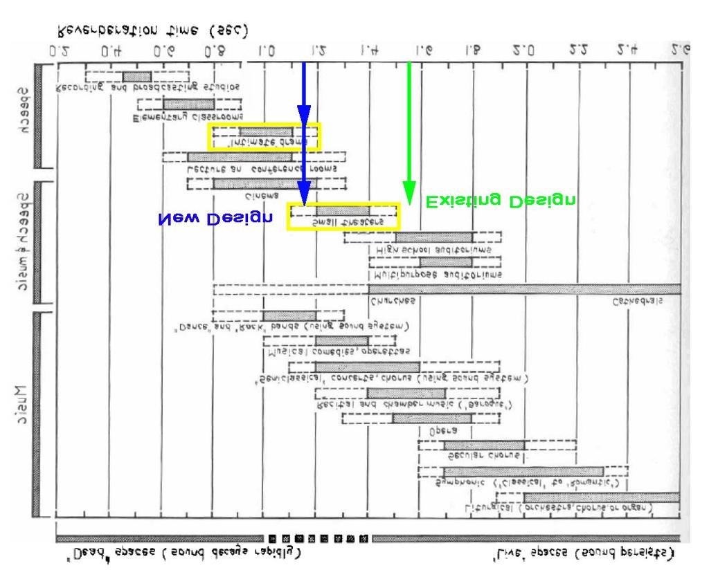
109 109

110 The New Design Materials The new acoustic design for the theatre has incorporated two new absorbing acoustical materials. In the new acoustic design for the theatre, two new sound-absorbing materials were incorporated to the existing design. On the orchestra level, the north and south entrance walls were covered with 2 thick fiberboard. Also a thin porous sound absorbing material was added to the back half of the theater s ceiling. Orchestra Level Plan Balcony Level 110
L ig h t in g Dept h 8
 Ligh t in g Dept h 8 Lighting Depth The Woolly Mammoth Theatre Company is a very unique group. They have a mission to provide new and edgy productions to the community. Therefore, when designing their
Woolly Mammoth Theatre. Washington DC
 Woolly Mammoth Theatre Washington DC Kate Feato Technical Report #1 Lighting Advisor: Dr. Mistrick Electrical Advisor: Professor Dannerth 04 October 2006 Executive Report The purpose of this technical
Lindsey Beane. Executive Summary
 Executive Summary The purpose of this technical assignment is to compile lighting information and make an analysis about the existing spaces. This report will include a list of the equipment used, required
Surface Materials. Surface Material Reflectance. Acoustic Ceiling 80% Tile. Painted Gypsum 75% Wall Board. Vinyl Composition 32% Tile
 Genetics Laboratory Space Description The Genetics Laboratory is located on the second floor of the laboratory building. The main functions of this space are as a learning and research area. There is a
Duke Tower Main Entrance Lobby Overview
 Duke Tower Main Entrance Lobby Overview This is the main entrance to the building that is located in the prominent tower portion of the building. The floor of this lobby has the Duke University School
Café DUSON- Overview
 Café DUSON- Overview Café DUSON is a study lounge with seating and tables to seat approximately 65 people in an area of about 1850 SF. The café is a double high space with full height windows on the North
University Park, PA. The Pennsylvania State University Architectural Engineering Lighting and Electrical Faculty Advisor: Dr.
 University Park, PA The Pennsylvania State University Architectural Engineering Lighting and Electrical Faculty Advisor: Dr. Martin Moeck A Building Overview The main spaces include: Convenience Store
Lobby Lighting Redesign
 Lobby Lighting Redesign Description of Space The lobby is located on the first floor of the building. Upon entering the building through the curved façade that features large expanses of glass, one would
Lighting Existing Conditions and Design Criteria Report Brian Regan Ltg./Elect. Virginia Historical Society 10/8/03
 Lighting Existing Conditions and Design Criteria Report Brian Regan Ltg./Elect. Virginia Historical Society 10/8/03 Executive Summary The existing lighting conditions and design criteria report describes
The Children s storytelling area
 Purpose of Space The Children s storytelling area This area has a circular seating pattern, in different levels going up. Its intended use is for librarians, parents, or young adults to read to children.
Exterior Façade Lighting Design
 Exterior Façade Lighting Design Duques Hall is located on George Washington campus in downtown Washington DC. It is located amidst some other university buildings, however, the façade is very visible from
Thesis Proposal. Brian Regan The Virginia Historical Society Building West Wing Addition RICHMOND, VIRGINIA
 Thesis Proposal Brian Regan The Virginia Historical Society Building West Wing Addition RICHMOND, VIRGINIA New Addition s Functions Auditorium Entrances located on ground and basement floors Museum Art
Jennifer Mers. Rio Hondo Library and Learning Resource Center. Executive Summary. General Building. Lighting/Electrical Option
 Executive Summary This assignment goes into depth into the existing lighting conditions of the Rio Hondo Library and Learning. The lobby, Reference Stacks and Microfilm Area, the Stack Area on the second
Technical Report One
 Technical Report One Yale Sculpture Building Lighting Conditions and Design Criteria Report: Technical Report 1 10.05.06 Prepared for: Dr. Richard Mistrick CC: Ted Dannerth Date: October 6, 2006 Executive
University of California Santa Barbara. Student Resource Building
 Student Resource Building Technical Assignment 1 October 16 th, 2006 1 Executive Summary The following report seeks to address the conditions of the proposed lighting system at the Student Resource Building
Technical Assignment I
 WHEELOCK COLLEGE CAMPUS CENTER AND STUDENT RESIDENCE 200 THE RIVERWAY, BOSTON, MA 02215 Technical Assignment I Lighting Existing Conditions and Design Criteria E X E C U T I V E S U M M A R Y The lighting
1.0 Introduction to Lighting Depth. 1.1 Hotel Tower Facace and Porte Cochere
 1.0 Introduction to Lighting Depth Dover Downs is primarily used for entertainment for the wealthy. When people go somewhere to spend money expectations are higher than usual. The lighting design for Dover
Lighting Existing Conditions and Design Criteria Report
 The building was constructed a few years ago to act as both a Headquarters and to be a display of what the product they manufacture can accomplish when put to work. The architecture of the building was
Lighting Existing Conditions and Design Criteria Report EXECUTIVE SUMMARY
 Lighting Existing Conditions and Design Criteria Report EXECUTIVE SUMMARY The Lighting Existing Conditions and Design Criteria Report will examine the existing lighting conditions in the (in general and
Lord Stirling Community School
 Lord Stirling Community School Schematic Design Proposal AE Senior Thesis Nehal M. Youssef About the Building A new face for an old town The building of the Lord Stirling Community School was the beginning
HARRY RANSOM HUMANITIES RESEARCH CENTER
 HARRY RANSOM HUMANITIES RESEARCH CENTER Additions and Renovations MICHAEL ANTHONY LOMBARDI Lighting/Electrical Emphasis Dr. Richard Mistrick, Advisor The Pennsylvania State University HARRY RANSOM HUMANITIES
Cosmetology Lab Redesign
 Cosmetology Lab Redesign Shane A. Semple - 25-4/5/2005 Design Concept: The Cosmetology Lab is a space that will be used for teaching students the trades of cutting hair, applying make-up, and doing manicures.
Schematic Design Proposal Presentation
 Steven A. Neimeister 9 December 2003 Architectural Engineering 481W AstroPower Headquarters Newark, Delaware Lighting/Electrical Option Consultant: Dr. M. Moeck Introduction to AstroPower Welcome to AstroPower!
Eric Anderson. Technical Report 1. Existing Lighting Conditions
 Eric Anderson Technical Report 1 Existing Lighting Conditions Executive Summary: The contents of Technical Report One include the evaluation of the lighting design and basic features of The Web Shop: The
HARRY RANSOM HUMANITIES RESEARCH CENTER
 HARRY RANSOM HUMANITIES RESEARCH CENTER EXPANSION AND RENOVATION THE UNIVERSITY OF TEXAS AT AUSTIN SCHEMATIC LIGHTING DESIGN LIGHTING / ELECTRICAL OPTION DR. RICHARD MISTRICK, ADVISOR THE HARRY RANSOM
Lighting Existing Conditions and Design Criteria Report
 page 1 of 19 Lighting Existing Conditions and Design Criteria Report The lighting in the includes very general lighting used in buildings with an office type setting. The fixture schedule for the Hall
LIGHTING EXISTING CONDITIONS SUMMARY EXECUTIVE SUMMARY Sara Lappano Ltg./Elec. Corron Cultural Center Middletown, VA
 LIGHTING EXISTING CONDITIONS SUMMARY EXECUTIVE SUMMARY Sara Lappano Ltg./Elec. Corron Cultural Center Middletown, VA 11.4.2002 Contained in this report is a summary of the lighting existing conditions
2.0 Lighting Depth Introduction
 2.0 Lighting Depth Introduction The lighting for four different spaces, the business news open office, first floor cafeteria seating, east lobby, and east façade, were analyzed and redesigned. The existing
Lighting Depth CAL IT 2. Brian Smith. Introduction
 Introduction Lighting Depth The University of California, San Diego Cal IT 2 building is a large research, academic building. As stated earlier, the building is used for lectures, laboratory experiments,
Overview. The Reading Room
 Overview The library for is the largest space in the George E. Bello Center. This space not only houses all the school s books and reference material, but there are computer terminals set up for students
Lighting Proposal Memo. Lighting Proposal. Angela Nudy Lighting/Electrical Dr. Mistrick Lighting Proposal Memo 1
 Lighting Proposal Angela Nudy Lighting/Electrical Dr. Mistrick 12.16.2006 Lighting Proposal Memo 1 Executive Summary I have chosen to redesign the lighting for four interior spaces and one exterior space
Advanced Lighting For Office
 Advanced Lighting For Office Open-Plan Office Applications High-Density 1 This High-Density 1 lighting application module presents alternative energy effective lighting design options for open-plan offices.
LIGHTING NORTH FAÇADE AND PLAZA
 LIGHTING NORTH FAÇADE AND PLAZA The main entry to UCI Natural Science Unit II is marked by a four-story glass curtain wall, an outdoor stair feature and a 5875 square foot landscaped plaza. Trees are located
Lobby Lighting Design
 Lobby Lighting Design The main lobby in Duques is hall is located on the first and second floor of the building. It is the main pathway in and out of the building for the more important spaces, such as
Lighting Existing Conditions and Design Criteria Report
 Lighting Existing Conditions and Design Criteria Report EXECUTIVE SUMMARY This report will describe the existing lighting system of the specific spaces of my redesign the auditorium, the atrium, the outdoor
Gathering Space. Function and Orientation. Space Characteristics Gregory Wolfe 2004 Senior Thesis Lighting / Electrical
 Gathering Space Function and Orientation The gathering space and reception area on the first floor is the first space you encounter upon entering the Westwood Community Church. As such, its purpose is
Franklin Square Hospital Center
 Franklin Square Hospital Center Baltimore, MD Thesis Proposal Cassandra Watson + Electrical Electrical Advisor Professor Dannerth Advisor Dr. Mistrick 16 December 2009 Table of Contents Executive Summary...
Center for Health Research and Rural Advocacy
 CHRRA Angela Nudy Pennsylvania State University Lighting/Electrical Option Faculty Advisor: Dr. Mistrick Images Compliments of Ewing Cole Brief Overview Location: Geisinger Health System Campus in Danville,
Executive Summary. CNBC Global Headquarters Christine Cajilig
 Executive Summary This report contains information about the existing lighting conditions for the CNBC Global Headquarters in Englewood Cliffs, New Jersey, including hardware, controls, power density,
Duke University Medical School. Duke School of Nursing
 Duke School of Nursing Lighting and Electrical Depth Proposal and Breadth Topics Proposal for Spring 2008 Semester December 18 th, 2007 Table of Contents Executive Summary....................................
Schematic Design Ideas for the Westlake Recreation Center. Presented by: Summer Padgett At Lutron Electronics On December 9, 2003
 Schematic Design Ideas for the Westlake Recreation Center Presented by: Summer Padgett At Lutron Electronics On December 9, 2003 The Westlake Recreation This facility serves as a park and recreation center
The Bahen Centre for Information Technology. Meeting Room Lighting Redesign. Introduction. University of Toronto ~ Toronto, Ontario, Canada
 Meeting Room Lighting Redesign Meeting Room #4287 Introduction The Meeting Room (room #4287) is located on the fourth floor within the grand spiral staircase in the atrium. The room is shaped like half
Spertus Institute of Jewish Studies
 2 Kanis Glaewktgarn Spertus Institute of Jewish Studies Lighting/Electrical Option 610 S Michigan Ave Chicago, IL Lighting Consultant: Dr. Kevin Houser September 29, 2008 Executive Summary This report
Main Lobby Area (North Vestibule thru South Vestibule):
:") Main Lobby Area (North Vestibule thru South Vestibule): Overview of Space: This is the entrance level from both the North, city street entrance, and the South, campus entrance. The space is 190 x 30 x
Main Lobby Area (North Vestibule thru South Vestibule): Overview of Space: This is the entrance level from both the North, city street entrance, and the South, campus entrance. The space is 190 x 30 x
Lighting Depth Study. Exterior Departure/Canopy Area
 Lighting Depth Study Exterior Departure/Canopy Area Overview The Exterior of the Indianapolis International Airport is consisted of 2 levels of traffic circulation. The lower level is the Arrival pick
University of California, San Diego Cal IT 2 Brian Smith. Schematic Design Presentation 06 December 2005
 University of California, San Diego Cal IT 2 Brian Smith Schematic Design Presentation 06 December 2005 Building Overview Location: University of California, San Diego Size: 220,000 s.f. Architect: NBBJ
SMEAL COLLEGE OF BUSINESS BUILDING University Park, PA
 SMEAL COLLEGE OF BUSINESS BUILDING University Park, PA Yena K. Han The Pennsylvania State University Architectural Engineering, Lighting/Electrical Faculty Advisor: Richard G. Mistrick, Ph.D., P.E., FIES
Technical Report #1 Existing Lighting Conditions and Design Criteria
 Technical Report #1 Existing Lighting Conditions and Design Criteria Lighting/Electrical Faculty Consultant: Table of Contents Executive Summary 1 Classroom A 2 Firing Range Area 8 Lobby and Corridors
Some Basics of School Library Design
 Some Basics of School Library Design Fred Schlipf and Ann Ohms 2018 Pull functional requirements together and put them in print BEFORE building planning begins In addition to the various items listed below,
Steve Neimeister 8 October 2003 AE 481W AstroPower Headquarters Newark, Delaware Lighting/Electrical Option Consultant: M. Moeck
 EXECUTIVE SUMMARY The will examine the existing lighting conditions in the (in general and specifically in the five spaces that will be redesigned) and compare it with respect to the IESNA lighting design
Multipurpose Room. Existing Conditions General Overview. Mark W. Miller Sibley memorial Hospital Grand Oaks Washington, DC
 Multipurpose Room ` N Figure 1: 1 st Floor Plan Multipurpose Room Location Existing Conditions General Overview The Multipurpose Room, as the name implies, serves as a multifunctional space for the Assisted
Thesis Proposal Update #2
 Thesis Proposal Update #2 Princeton Theological Seminary Library Princeton, NJ Stephanie Deckard Lighting Electrical Faculty Advisor Dr. Kevin Houser 3/11/2013 Executive Summary The Princeton Theological
TECHNICAL ASSIGNMENT #3: SCHEMATIC LIGHTING DESIGN
 TECHNICAL ASSIGNMENT #3: SCHEMATIC LIGHTING DESIGN Jason Weaver 12/13/2007 Background The central role of a college is to help students develop a worldview. The three things one needs to understand in
THE COMPLETE GUIDE TO OUTDOOR WALL LIGHTS
 THE COMPLETE GUIDE TO OUTDOOR WALL LIGHTS CONTENTS 1. INTRODUCTION 2. TYPES OF OUTDOOR WALL LIGHTS 3. LIGHT SOURCES IN OUTDOOR WALL LIGHTS 4. FACTORS IN SELECTING OUTDOOR WALL LIGHTS 5. SUMMARY lighting
COMMERCIAL LIGHTING DESIGN GUIDE
 COMMERCIAL LIGHTING DESIGN GUIDE WHAT SETS US APART INNOVATION We combine the latest energy efficient technology and design styles to create an extensive range of attractive and sustainable luminaires.
Hawthorn Building. Penn State Altoona Campus Altoona, PA. Walter Nichols. Lighting/Electrical Option Faculty Advisor: Dr.
 Hawthorn Building Penn State Altoona Campus Altoona, PA Walter Nichols Lighting/Electrical Option Faculty Advisor: Dr. Richard Mistrick 58,800 sq.ft. 2 Stories above grade Steel frame with curtain wall
Existing Area Description: The area is an angle around the North point of the building. It is a wide patio wrapping the façade of the building.
 Exterior Street Entrance: Overview of Space: The street entrance is the main entrance for the members of the community who are entering the library. The purpose of this space is to effectively and aesthetically
Dorrance H. Hamilton Building
 Dorrance H. Hamilton Building Josh Kreutzberger Penn State Architectural Engineering Technical Report 3 Advisor: Dr. Mistrick Site Overview Martin Building December 2006 Scott Library & Administrative
Mezzanine Youth Area:
 Mezzanine Youth Area: Overview of Space: This is located as a shorter level on the Northeast corner of the building, between the ground and second levels two levels have been placed. The design is to allow
Senior Thesis Presentation
 Senior Thesis Presentation 5th Year Architectural Engineering Lighting/ Electrical Option Advisors: Dr. Mistrick & Prof. Dannerth Building Overview Size: 104, 000 square feet on 4 levels (3 stories above
The New York University Concourse Project. New York City. Existing Conditions and Design Criteria
 The New York University Concourse Project New York City Existing Conditions and Design Criteria Kevin Hsia Lighting/Electrical Option Advisor: Dr. Richard Mistrick September 29, 2008 executive summary
Shepherd University Wellness Center AE 481 Revised Thesis Proposal
 A E 481 REVISED THESIS PROPOSAL Shepherd University Wellness Center AE 481 Revised Thesis Proposal Shepherdstown, West Virginia Lighting/ Electrical Option Dr. Houser and Professor Dannerth March 24, 2011
Corbin Building. Technical Assignment 2. Matthew Trethaway Lighting/ Electrical AE 481W 10/26/2011 Advisor: Ted Dannerth
 Corbin Building Technical Assignment 2 Matthew Trethaway Lighting/ Electrical AE 481W 10/26/2011 Advisor: Ted Dannerth 10/26/2011 Technical Report II 1 Executive Summary The following report is an overview
Quality of the Visual Environment
 Quality of the Visual Environment IES Illuminating Engineering Society The IES is the recognized technical authority on illumination. For over ninety years its objective has been to communicate information
City of Green Administration Building. Brian Koze November 12, Lighting Schematic Design Presentation
 City of Green Administration Building Brian Koze November 12, 2010 Lighting Schematic Design Presentation Building Statistics Location City of Green, Ohio Occupant City of Green Administration Size 53,671
Kimberly Morton The Pennsylvania State University Architectural Engineering Program Lighting/Electrical Faculty Advisor: Dr.
 Kimberly Morton The Pennsylvania State University Architectural Engineering Program Lighting/Electrical Faculty Advisor: Dr. Martin Moeck Building Location COSI (Center Of Science and Industry) is located
Schematic Design Presentation December 15, 2006 David Smith
 Schematic Design Presentation December 15, 2006 David Smith Overview Located in Lancaster, PA 65,000 square feet 4 stories, 3 above grade Architect of record is Philip Johnson-Alan Ritchie Architects Ground
UBC Technical Guidelines Section Edition Interior Building Lighting Page 1 of 5
 Page 1 of 5 1.0 GENERAL 1.1 Related UBC Guidelines.1 Section 27 05 05 Communication Rooms Design Guidelines 2.13 1.2 Coordination Requirements.1 UBC Energy & Water Services.2 UBC Building Operations Electrical
13-15, 2001 USING LIGHTING SIMULATION TO ASSESS THE PERFORMANCE OF AND INDIRECT OFFICE LIGHTING SYSTEMS IN DYNAMIC WORKPLACES
 Seventh International IBPSA Conference Rio de Janeiro, Brazil August 13-15, 2001 USING LIGHTING SIMULATION TO ASSESS THE PERFORMANCE OF AND INDIRECT OFFICE LIGHTING SYSTEMS IN DYNAMIC WORKPLACES R. Ries,
Oregon Non-Residential Building Energy Code
 Oregon Non-Residential Building Energy Code Interior Connected Lighting Power Requirements The requirements for interior lighting power are one of the most important sections of the Oregon Energy Code.
Depth Work Part 1: Lighting Design
 During the upcoming spring semester I will be investigating and redesigning some of the systems in Redifer Commons. This thesis study will be composed of three sections, which will all end up intertwining.
Jamie Devenger Senior Thesis Princeton University Sherrerd Hall 1 Lighting Proposal Memo September 11, 2009
 Jamie Devenger Senior Thesis Princeton University Sherrerd Hall 1 I am proposing to study five spaces for the lighting portion of my thesis. The spaces to be analyzed and redesigned are as follows: Large
Executive Summary. Houston Museum of American Art New York, New York
 Executive Summary This proposal details the work to be completed in the spring of 2013. It presents a description of the redesign of several systems present in the. Included are explanations of two depth
THE AUGUST WILSON CENTER FOR AFRICAN AMERICAN CULTURE PITTSBURGH, PENNSYLVANIA. PERKINS + WILL chematic Design Presentation MICHAEL P.
 PITTSBURGH, PENNSYLVANIA PERKINS + WILL chematic Design Presentation MICHAEL P. ROYER SCHEMATIC DESIGN PRESENTATION: PROJECT OVERVIEW LOCATION: Liberty Avenue Pittsburgh, Pennsylvania SIZE: 63,000 Square
Chandler City Hall Chandler, Arizona
 Chandler City Hall Chandler, Arizona Thesis Proposal AE481W: Architectural Engineering Senior Thesis Friday December 10 th, 2010 Stephanie Romanias Lighting/Electrical Faculty Consultants: Dr. Kevin Houser
USG LIBRETTO GMS CEILING ILLUMINATION OPPORTUNITIES
 01 June, 2007 USG LIBRETTO GMS CEILING ILLUMINATION OPPORTUNITIES The Libretto GMS ceiling system allows for a wide variety of creative illumination opportunities. Lighting can be integrated from both
Advances in Non-Residential Lighting Technologies
 Advances in Non-Residential Lighting Technologies CABEC conference San Diego, CA October 21, 2011 Steven Mesh, LC, IESNA Lighting Education & Design 140 Gardenside Drive, #304 San Francisco, CA 94131 415-516-8126
Holy Cross Hospital North Addition. Fall 2005 Phil Mackey
 Holy Cross Hospital North Addition Fall 2005 Phil Mackey 1 Existing Design 2 Existing Design Building Functions: 1 st floor consists of the new main entrance/lobby, concourse, conference center with multi-purpose
Technical Report IVb: Proposal
 Technical Report IVb: Proposal jack risser lighting/electrical s. good the nerman museum overland park, kansas dec 13 th, 2013. 2 Executive Summary: In this report, a proposal of work to be complete and
Technical Assignment 1 Existing Lighting Conditions and Design Criteria
 Technical Assignment 1 Existing Lighting Conditions and Design Criteria Jason Greer Lighting/Electrical Option AGI Files: P:\AE 481\Technical Assignment 1\AGI Files October 5, 2007 Table of Contents Table
Table of Contents. Parts 1 & 2 Descriptions and Design Considerations Part 3 Evaluation and Critique of Existing Lighting Systems...
 Mi chaelp.gardner l i ght i ng/ e l e c t r i c al Techni calreporti october3,2008 ami xe dus epr oj e c ti nt he Eastern uni ted states Table of Contents Parts 1 & 2 Descriptions and Design Considerations...
Shepherd University Wellness Center AE 481 Thesis Proposal
 A E 481 THESIS PROPOSAL Shepherd University Wellness Center AE 481 Thesis Proposal Shepherdstown, West Virginia Lighting/ Electrical Option Dr. Houser and Professor Dannerth December 10, 2010 Executive
Lighting System Conceptual Design
 Kevin Michael Danna Penn State Architectural Engineering Senior Thesis BUILDING OVERVIEW One Christina Crescent is a six story office building located in Wilmington, Delaware and is home to Barclays Bank
Lighting Depth Part 1: Exterior Space
 Lighting Depth Part 1: Exterior Space Metaphor and Ideas: The first space of my lighting redesign is the front façade of the Recreation Center shown below. Metaphorically, I want the front porch to act
Lighting Concepts: Residential
 Concepts: Residential Residential This IESNA chapter serves as a guide for lighting residential spaces. It is intended to aid in creating lighted spaces that are rich and varied and have adequate lighting
SUPERMARKET LIGHTING DESIGN GUIDE
 SUPERMARKET LIGHTING DESIGN GUIDE WHAT SETS US APART INNOVATION We combine the latest energy efficient technology and design styles to create an extensive range of attractive and sustainable luminaires.
Lighting Depth: Courtyard Franklin Care Center, Franklin Lakes, NJ
 Lighting Depth: Courtyard Courtyard Overview: The perimeter buildings of the Franklin Care Center wrap around the central two story building creating two courtyard areas. The courtyard is entered through
Related Sections: TBD. Effective Date: January 1, 2016
 Description: The purpose of the section is to highlight the current applicable UMCP Design Standards for the design, selection and, installation of lighting fixtures within buildings. Related Sections:
ANNIVERSARY
 Lighting the way. TH ANNIVERSARY 1942 2017 Lighting in Design Applications Under Cabinet Lighting P. 8 Interior Cabinet Lighting P. 10 Drawer Lighting P. 12 Down Lighting P. 14 Mirror Lighting P. 16 Shelf
student National Lighting Design Competition Winners 2010
 student National Lighting Design Competition Winners 2010 winner student Hiroki Usui Project: FUEL Convenience Store/Gas Station School: Washington State University, Spokane, WA Cooper Lighting s 34th
[Lighting Proposal Memo ] Hotel and Conference Center Virginia, USA
![[Lighting Proposal Memo ] Hotel and Conference Center Virginia, USA](/thumbs/87/95888407.jpg "[Lighting Proposal Memo ] Hotel and Conference Center Virginia, USA") 2010 2011 Hotel and Conference Center Virginia, USA Haley L. Darst Lighting Electrical Faculty Advisor: Dr. Kevin Houser September 12, 2010 [Lighting Proposal Memo ] The following document contains a description
2010 2011 Hotel and Conference Center Virginia, USA Haley L. Darst Lighting Electrical Faculty Advisor: Dr. Kevin Houser September 12, 2010 [Lighting Proposal Memo ] The following document contains a description
NRG SYSTEMS, HINESBURG, VT
 Daylighting Case Studies NRG SYSTEMS, HINESBURG, VT Project Highlights Daylight windows separated from view windows Advanced daylightredirecting blinds Low partitions, with desks oriented at right angles
Lighting Design Criteria: Codes and Standards
 EXTERIOR LIGHTING Lighting Design Criteria: Codes and Standards IESNA Lighting Handbook 10 th Edition RP-33-14 Lighting for Exterior Environments ASHRAE/IES Standard 90.1-2010 IBC 2012 2 Site Lighting
Table of Contents. Heather Lion Redifer Commons University Park, PA. General Lamp and Ballast Information 1-2
 Table of Contents General Lamp and Ballast Information 1-2 Large Work Space: Dining Rooms Dining Room 103 3-6 Dining Room 117 7-11 A La Board Dining 12-18 Mongolian Grill 18-21 Serving Prep 21-22 Marche
RETAIL LIGHTING DESIGN GUIDE
 RETAIL LIGHTING DESIGN GUIDE 2 WHAT SETS US APART INNOVATION We combine the latest energy efficient technology and design styles to create an extensive range of attractive and sustainable luminaires. We
1.1.0 Exterior Facade
 1.1.0 Exterior Facade 1.1.1 Introduction As a primary marketing tool for potential residents unfamiliar with the Rochester area, the façade lighting calls for aesthetic appeal that meets the requirements
Perot Museum of Nature and Science Final Lighting Design Presentation. Yucheng Lu, Lighting Electrical, Adviser: Shawn Good
 Perot Museum of Nature and Science Final Lighting Design Presentation Yucheng Lu, Lighting Electrical, Adviser: Shawn Good Introduction Dallas Museum of Natural History Established in 1936, Dallas Museum
Electrical Systems. Electrical Plans. Electrical Plans. Essential to ensure. National Electrical Code (NES) Consider electrical needs.
 Consider electrical needs.") Electrical Systems Electrical Plans Essential to ensure Proper wiring National Electrical Code (NES) Electrical Plans Consider electrical needs Office equipment Lighting E t t i t t Entertainment systems
Electrical Systems Electrical Plans Essential to ensure Proper wiring National Electrical Code (NES) Electrical Plans Consider electrical needs Office equipment Lighting E t t i t t Entertainment systems
RESIDENTIAL LIGHTING DESIGN GUIDE
 RESIDENTIAL LIGHTING DESIGN GUIDE WHAT SETS US APART INNOVATION We combine the latest energy efficient technology and design styles to create an extensive range of attractive and sustainable luminaires.
B. It is recognized that these standards are updated irregularly and lighting technology is changing rapidly.
 PART 1 GENERAL 1.01 Lighting design: A. Reference UAF Facilities Services Guidelines for Average Illumination Levels. B. It is recognized that these standards are updated irregularly and lighting technology