Sapphire Series TSVW & TWWS Chillwater Digital Thermostats
|
|
|
- Belinda Daniel
- 5 years ago
- Views:
Transcription


1 Sapphire Series TSVW & TWWS Chillwater Digital Thermostats
2 Table of Contents 1. Introduction 3 TSVW Main Components 3 TWWS Main Components 4 2. Display Panels for TSVW and TWWS Thermostats 4 TSVW Display Panel Features 5 TWWS Display Panel Features 6 Display Panel Feature Descriptions 7 3. Power Module Box 8 PC Board Features 9 PC Board Jumpers 10 PC Board Fuses 10 PC Board External Wiring Connections Operation of Controls Programming Mode 12 Programmable Parameter Chart 13 Fault Codes Controls Operation Flow Charts & Diagrams 14 Water Valve Operation 15 Heater Operation 15 Auto Fan Speed Operation 16 Fan Speed Process Diagram 17 Cooling Mode Process Diagram 18 Heating Mode Process Diagram 19 Heater Process Diagram 20 Auto Mode Process Diagram 21 Dehumidification Process Diagram Wiring Diagrams Component Dimensions 27 TSVW 27 TWWS 28 i:\wordpfct\ TSVW-TWWS Manual-Table-of-Contents.wpd
3 1. Introduction The Aqua-Air Sapphire TSVW and TWWS Series Chillwater Thermostats has been designed specifically to operate chillwater fan coils. These fan coils will usually have a fan motor(s) and 3 way water regulating valve. They may also be equipped with an integral or remote heating element. All of these components can be regulated by the TSVW and TWWS Thermostats. The only difference between the TSVW and TWWS digital thermostats are the display heads. The TSVW Thermostat utilizes the TSV-01 Display Head along with a Vimar bezel. The TWWS Thermostat uses the TWWS-01 Display Head which is physically the same size as the older TW digital thermostats The TSVW Thermostat is comprised of the following main components: 1. Display Panel ( TSV-01 ) 2. Display Cable ( TSWDC-15 ) 3. Power Module Box ( TSVW-02 ) 4. Room Air Sensor ( TW2-SENSOR-07 ) 5. Water Sensor ( TW2-SENSOR-07 ) 3
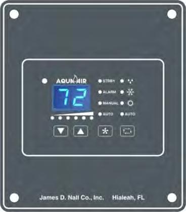
4 The TWWS Thermostat is comprised of the following main components: 1. Display Panel ( TWWS-01 ) 2. Display Cable ( TSWDC-15 ) 3. Power Module Box ( TSVW-02 ) 4. Room Air Sensor ( TW2-SENSOR-07 ) 5. Water Sensor ( TW2-SENSOR-07 ) 2. Display Panel The TSV-01 Display Panel is the user interface with the TSVW Thermostat and the TWWS-01 Display Panel is the user interface with the TWWS Thermostat. They allow the user to make all necessary changes to operating modes, temperature settings and fan speed settings. They also allows the user to make changes to a set of Programming Parameters that controls many of the features of the thermostat. The TSV-01 Display Panel has been designed to use the Vimar Idea Series metal bezels giving you an almost unlimited number of color options to match any decor. The bezel snaps on and off easily and it hides all of the mounting screws for the display panel On the following two pages are diagrams showing all of the features of the two display panels. Each feature has a number associated with it. Descriptions for each feature begin on the page following the diagrams. 4
5 5
6 6
7 Features of the TSV-01 and TWWS-01 Display Panel are: 1. MODE BUTTON - The Mode Button is used to select one of the four operating modes and standby (off) mode. Pressing and releasing the Mode Button will advance you to the next mode. Continue to do this until you have reached the desired mode. The available modes are as follows: STANDBY DEHUMIDIFICATION COOLING HEATING AUTO Thermostat is OFF, no Cooling or Heating functions are available. The fan can be operated in the Manual mode. Indicated by LED 11. Thermostat is in the Dehumidification Mode indicated by LED 14. Thermostat is in the Cooling Mode only, indicated by LED 15. Thermostat is in the Heating Mode only, indicated by LED 16. Thermostat is in the Auto Mode where it will automatically choose between Cooling and Heating as the room temperature dictates. This mode is indicated by LED FAN BUTTON - The Fan Button is used to select between AUTO and MANUAL Fan Speed Control as indicated by LED s 12 and 13 respectively. To go from AUTO to MANUAL Mode press the Fan Button once. To change Fan Speeds while in MANUAL Mode press the Fan Button once and then the Up or Down Button to increase or decrease, respectively, the Fan Speed. To switch from MANUAL to AUTO Mode press the Fan Button twice 3. UP BUTTON - The Up Button is used to increase values for set points, fan speeds and programmable parameters. During normal operation, momentarily pressing the Up Button will display the Set Point. Continued pressing of the Up Button will increase the Set Point 4. DOWN BUTTON - The Down Button is used to decrease values for set points, fan speeds and programmable parameters. During normal operation, momentarily pressing the Down Button will display the Set Point. Continued pressing of the Down Button will decrease the Set Point. To view the Chillwater Inlet Temperature sensed by the TSVW Water Sensor. 1. Press and HOLD the Down Button (4) 2. Press and RELEASE the Up Button (3) This will display the temperature sensed by the TSVW Water Sensor. 5. FAN SPEED LED s - These six LED s indicate the current Fan Speed 1-6. Low Speed (#1) is the left most LED and High Speed (#6) is indicated by the LED on the far right. 7
8 F+ LED - Indicates that the actual temperature displayed is in excess of 100 F. Add the value displayed to 100 to get the actual temperature. If the 100 F LED is lit and the display shows 10 then the actual temperature would be 110 F. 7. MAIN DISPLAY - This is a 2 digit, 7 segment LED display. Normally the current room temperature is displayed. It can also display the Set Point, Water Temperature, Programmable Parameters and Alarm codes. 8. WATER VALVE / ELECTRIC HEAT LED - This LED indicates if the Water Valve output has been turned on (in either the Cooling or Heating mode) or, if an Electric Heater is being used and the control has been programmed for it (Programmable Parameter A5 = EL), it will indicate when the Electric Heater output is energized. 9. FACEPLATE AIR SENSOR - The TSVW can use either this Faceplate Air Sensor to sense the room temperature or the Air Sensor that is plugged into the Power Module PC Board. This is selected by Programmable Parameter B1. If the Faceplate Sensor is used it is not necessary to have the Air Sensor plugged into the PC Board. 10. ALARM LED - Indicates that the control is in a fault condition. 11. STANDBY MODE LED - Indicates that the control is in the Standby Mode. All Cooling and Heating functions are turned off. If the fan is in the Auto Mode then it will be turned off. If the Fan is in the Manual Mode then the Fan will still operate at the last fan speed selected. 12. MANUAL FAN LED - Indicates the Fan Speed is in the Manual Speed Selection Mode 13. AUTO FAN LED - Indicates the Fan Speed is in the Automatic Speed Selection Mode 14. DEHUMIDIFICATION MODE LED - Indicates that the control is in the Dehumidification Mode 15. COOLING MODE LED - Indicates the control is in the Cooling Mode 16. HEATING MODE LED - Indicates the control is in the Heating Mode 17. AUTO COOL/HEAT MODE LED - Indicates the control is in the Automatic Cooling or Heating Mode. In this mode the control will automatically select, based on the room temperature and the set point, whether the control is operating in the Cooling or Heating Mode. 3. Power Module Box The Power Module Box is comprised of the Main Power PC Board enclosed inside of an aluminum enclosure. The PC Board s main features are shown on the following page. 8
9 9
10 POWER MODULE PC BOARD JUMPERS Jumper Description Type Specification Notes JP1 Chillwater / Direct Expansion Selection Wire JP3 Heater Relay Test 3 pos. pin JP5 Water Valve Relay Test 3 pos. pin C/W: Jumper Cut D/X: Jumper Not Cut Install jumper in positions 1 & 2 to energize the heater Install jumper in positions 1 & 2 to energize the water valve Do not cut with power applied to board. POWER MODULE PC BOARD FUSES Fuse Description Fuse Amperage Rating Fuse Size Part Number F1 Protects against a line voltage short circuit on the primary side of the transformer TX 500 ma ( 1/2 A ) 5mm x 20mm TWS-PCBFUSE1 F2 Protects against a short circuit on the Heater or Water Valve Circuits 20 A 5mm x 20mm TWS-PCBFUSE1 F3 Protects against a control circuit short circuit on the secondary side of the transformer TX 500 ma ( 1/2 A ) 5mm x 20mm TWS-PCBFUSE1 Basic External Wiring Connections to the TSVW & TWWS PC Board Located in the Power Module Box 10
11 4. Chillwater Operation Below are the steps necessary for the basic operation of the control. Entering the Cooling Mode Press and release the Mode Button (1) until the Cooling Mode LED (15) is lit. Entering the Heating Mode Press and release the Mode Button (1) until the Heating Mode LED (16) is lit. Automatic (Auto) Cool / Heat Mode Press and release the Mode Button (1) until the Auto LED (17) is lit Entering the Dehumidification Mode Press and release the Mode Button (1) until the Dehumidification Mode LED (14) is lit. Turn the Control OFF (Standby Mode) Press and release the Mode Button (1) until the Standby Mode LED (11) is lit. View the Set Point Temperature Press and release either the Up Button (3) or the Down Button (4). Increasing the Set Point Temperature Press and release the Up Button (3) until you reach the desired temperature Decreasing the Set Point Temperature Press and release the Down Button (4) until you reach the desired temperature Putting the Fan Mode into Manual Press and release the Fan Button (2) until the Manual Fan LED (12) is lit Increasing the Fan Speed in the Manual Fan Mode Press and release the Fan Button (2) and then press and release the Up Button (3) until you reach the desired speed as indicated by the Fan Speed LED s (5). Decreasing the Fan Speed in the Manual Fan Mode Press and release the Fan Button (2) and then press and release the Down Button (4) until you reach the desired speed as indicated by the Fan Speed LED s (5). Putting the Fan Mode into Auto Press and release the Fan Button (2) twice Displaying the Chillwater Inlet Temperature at the Fan Coil Press and hold the Down Button (4) then press and release the Up Button (3) Changing the Fan Speeds in the Standby Mode Press and release the Up Button (3) or the Down Button (4) until the desired speed is reached. To turn the fan off in the Standby Mode press the Down Button (4) until all of the Fan Speed LED s are off. 11
12 5. Entering the Programming Mode There are currently 14 different programmable parameters in the TSVW Thermostat. All of these parameters can be changed from the Display Panel with some simple keystrokes. The Program Mode can ONLY be entered while the control is in the Standby Mode To Program the TSVW Control: 1. Press the Mode Button until the control is in the Standby Mode which is indicated by the Standby Mode LED (11) 2. Press the Up Button and the Down Button at the SAME time. The first Programmable Parameter code P1" will appear in the window for 2 seconds and then the P1 setting that is currently stored in the control will appear. 3. To change the parameter setting press and release the Up or Down Buttons. 4. The Fan Button advances you to the next parameter. Advancing to the next parameter SAVES the previous parameter setting. If you do not advance to the next parameter the setting WILL T BE SAVED unless you press the Mode Button to exit the Programming Mode (see 5 below). 5. Pressing the Mode Button exits the Programming Mode. Any changes made to any of the parameter settings will be saved. 6. If you do not press any buttons for 30 seconds the control will automatically exit from the Program Mode. The last parameter change will T BE SAVED. 12
13 Programmable Parameters Parameter Number Description Default Range P1* High Fan Speed Limit (% of input voltage) " ( 100 = 00. ) P2* ** Low Fan Speed Limit (% of input voltage) P3 Unused-Reserved for future applications N/A N/A P4 Temperature Sensor Calibration 0-10 to +10 F P5 to P8 Unused-Reserved for future applications N/A N/A P9 Display LED Brightness Control 13 4 = minimum 13 = maximum A1 Displays F or C F F / C A2 Unused-Reserved for future applications N/A N/A A3 Reverse Fan Speed in Heating Mode re A4 A5 A6 Continuous Fan Operation or Cycling on Demand Hot Water Heating or Electric Element Heat Fan Motor Type, Shaded Pole or Split Capacitor A7 Reset Memorized Programming Defaults no A8 A9 b1 Force Water Valve Open for 4 Hours to Bleed the Air from the Chillwater Loop Ambient Air to Chilled Water Temperature Differential Air Temperature Sensed from the Display Panel or the Air Sensor connected to the PC Board Co Of SP no No = Normal re = Reverse CY = Cycle Co = Continuous Of = Hot Water EL = Electric Heat SP = Shaded Pole SC = Split Capacitor no = Normal Rs = Reset Default no = Normal Operation op = Open 15 F 5 to 25 F on on = PC Board of = Display Panel b2 Delay Before Fan Turns Off 30s seconds * P1 and P2 values are expressed as a percentage of the input voltage. If the setting for P1 is 90 then the maximum voltage output at high fan speed (speed 6) will be approximately 90% of the input voltage. As you are changing the settings in P1 and P2 the fan will operate and change according to the settings you are entering. ** If Electric Heat is selected ( A5 = EL ) then P2 must T be set lower than 50 and parameter b2 must be set to a minimum of 60 seconds. 13
14 FAULT CODES Code E1 LA AA Description Display cable damaged. Check to see if the cable has been cut or otherwise damaged. Low Voltage Input to Power Module Box. Check your incoming voltage to the Power Module Box and verify that it is within +/-10% of the rated voltage Air Sensor Failure or Disconnected. If you get this error code and you intend to use the air sensor on the Display Panel change Parameter b1 to of. 6. Control Operation Flow Charts and Diagrams On the following pages are flow charts and graphic representations of how the control operates the water valve, fan and heater (if so equipped) in each of the 4 operating modes. Some of the abbreviations are as follows: TERM Abs DELTA Hysteresis LED Tair Twater Definition Absolute Value. The Absolute Value of 5 is 5. The Absolute Value of (-3) is 3. The Absolute Value of an equation that returns a negative number is always a positive number. Therefore Abs (3-8) = 5 Difference between two values. As used in this manual it is the difference between two temperatures The lag between making a change, such as increasing or decreasing temperature, and the response or effect of that change. It typically refers to turn-on and turn-off points. For example, if a thermostat set for 70 degrees turns on when the temperature reaches 68 and turns off at 72, the hysteresis is the range from 68 to 72. Light Emitting Diode. These are all of the lights on the display panel. The two 7 segment numerical displays are each made up of 7 individual diodes. Air Temperature as sensed by either the Display Panel or Room Air Sensor Water Temperature as sensed by the Water Sensor To Ambient air to chillwater differential. This is set in P18. Tset Set Temperature of the thermostat 14
15 15
16 16
17 FAN OPERATION & SPEED SELECTION FAN CYCLING MODE P13 CYC HEATING or COOLING CON TIMER > b2 AUTO MODE DELTA < 1 DELTA > 6 PROGRAMMED SPEED SPEED = 1 SPEED = 6 SPEED = DELTA FAN OFF Normal Fan Operation DELTA = Abs( Tair - Tset ) Reverse Fan Operation DELTA = Abs[ Abs( 17 Tair - Tset) - 6 ]
18 COOLING MODE COOL AIR PROBE Tair>(Tset+1) VALVE ON (Tair-Twater) < (To-8) MIN FAN SPEED OR MANUAL SPEED VALVE OFF (Tair-Twater) < To VALVE ON VALVE OFF SELECTED FAN SPEED Tair < ( Tset - 1) To = Ambient air to Chillwater 18Temperature Differential A9
19 HEATING MODE HEAT AIR PROBE Tair < (Tset-1) VALVE ON (Twater-Tair) > (To-8) MIN FAN SPEED OR MANUAL SPEED VALVE OFF (Twater-Tair) > To VALVE ON VALVE OFF SELECTED FAN SPEED Tair > ( Tset - 1) To = Ambient air to Chillwater 19Temperature Differential A9
20 ELECTRIC HEATER ELECTRIC HEAT HEATING OFF VALVE? ON (Twater-Tair) > (To+7) HEATER OFF HEATER OFF HEATER ON To = Ambient air to Chillwater Temperature Differential A9 20
21 AUTO MODE AUTO HEAT or COOL HEAT COOL (Tair - Tset) < -2 (Tair - Tset) > 2 COOLING MODE HEATING MODE COOLING MODE 21
22 DEHUMIDIFICATION MODE DEHUMIDIFICATION MODE SELECTING DEHUMIDIFICATION WAIT 1 MINUTE FAN ON WAIT 30 MINUTES COOLING CYCLE WAIT 1 HOUR or until ( Tair - Tset ) < -2 WAIT 4 HOURS 22
23 23
24 24
25 25
26 26
27 27
28 28
mini-kool series INSTALLATION, OPERATION & MAINTENANCE rev 04/09
 mini-kool series INSTALLATION, OPERATION & MAINTENANCE 80806-1 rev 04/09 TABLE OF CONTENTS INTRODUCTION... 1 PRODUCT OVERVIEW... 1 The mini-kool self contained unit... 1 Thermostat / Controllers... 3 Seawater
Aqua-Air Tempwise 2001 Chillwater Digital Thermostat. Operating Manual. Aqua-Air Manufacturing division of the James D. Nall Co., Inc.
 Aqua-Air Tempwise 2001 Chillwater Digital Thermostat Operating Manual Aqua-Air Manufacturing division of the James D. Nall Co., Inc. 1050 East 9th Street Hialeah, FL 33010 U.S.A. Phone (305) 884-8363 Fax
AH-Elite Control (for CW systems)
") AH-Elite Control (for CW systems) OPERATIONS MANUAL Dometic Marine Rev. 20091102 L-2229 English COPYRIGHT 2007-2009 Dometic Marine. All Rights Reserved. No part of this publication may be reproduced, translated,
AH-Elite Control (for CW systems) OPERATIONS MANUAL Dometic Marine Rev. 20091102 L-2229 English COPYRIGHT 2007-2009 Dometic Marine. All Rights Reserved. No part of this publication may be reproduced, translated,
OTCW-FX1 For Chilled Water A/C Systems OPERATOR S MANUAL. Technicold Marine Systems
 OTCW-FX1 For Chilled Water A/C Systems OPERATOR S MANUAL Technicold Marine Systems www.technicold.com Technicold by Northern Lights 1419 W. Newport Center Drive Deerfield Beach, FL 33442 Tel: (954) 421-1717
ITC 2000 HEATING CONTROL CABINET. Installation & Operation Manual
 ITC 2000 HEATING CONTROL CABINET Installation & Operation Manual VTI, Incorporated 24 McMillan Way Newark, DE 19713 Phone (302) 738 0500 FAX (302) 738 6594 Revision Level 0.03 Manual No. 90003314 June,
AH-Passport I/O (for CW systems)
") AH-Passport I/O (for CW systems) OPERATIONS MANUAL AH-Passport I/O Compact AH-Passport I/O (legacy model) Dometic Marine Rev. 20090710 L-2232 English COPYRIGHT 2007-2009 Dometic Marine. All Rights Reserved.
AH-Passport I/O (for CW systems) OPERATIONS MANUAL AH-Passport I/O Compact AH-Passport I/O (legacy model) Dometic Marine Rev. 20090710 L-2232 English COPYRIGHT 2007-2009 Dometic Marine. All Rights Reserved.
1.1 Instructions for the o-led Display/Controller
 1.1 Instructions for the o-led Display/Controller The Marvair o-led digital display/controller operates on board reverse cycle air conditioning equipment to provide room temperature control and humidity
OCT For Cool Touch Controller OPERATOR S MANUAL. Technicold Marine Systems
 OCT For Cool Touch Controller OPERATOR S MANUAL Technicold Marine Systems www.technicold.com Technicold by Northern Lights 1419 W. Newport Center Drive Deerfield Beach, FL 33442 Tel: (954) 421-1717 Fax:
OT-FX2 OLED TOUCH for the FX II Touch control panel OPERATOR S MANUAL. Technicold Marine Systems
 OT-FX2 OLED TOUCH for the FX II Touch control panel OPERATOR S MANUAL Technicold Marine Systems www.technicold.com Technicold by Northern Lights 1419 W. Newport Center Drive Deerfield Beach, FL 33442 Tel:
tcm100, tcm101 Series Temperature Control Modules and PTS100, PTS100/3 Pipe Temperature Sensors Operations Manual
 tcm100, tcm101 Series Temperature Control Modules and PTS100, PTS100/3 Pipe Temperature Sensors Operations Manual This manual covers operation of the tcm100 and tcm101 Series Temperature Control Modules.
Contents. FX-1 Operations Manual Micro Air Corporation 124 Route 526 Allentown, NJ 08501
 Contents FX-1 Operations Manual Micro Air Corporation 124 Route 526 Allentown, NJ 08501 INTRODUCTION... 1 BASIC OPERATION... 2 SYSTEM OVERVIEW... 3 OPERATOR CONTROLS AND DISPLAY PANEL... 4 & 5 DUAL BUTTON
SAT- 3 Installation Setup Guide
 SAT- 3 Installation Setup Guide Date: 4 February 2016 Issue: 2 Applies to: SAT- 3 room temperature controller, part number 201-000- 146 Contents 1. Quick Start Guide...2 1.1. General... 2 1.1.1. Installation
Pump-Down Controller MODEL 4052
 Pump-Down Controller 4-20mA Input/Scalable Output Seal Fail Monitoring Duplex Pump Alternation Hand-Off-Auto Controls Dual Run-time Meters RS-485/Modbus Communications DESCRIPTION The Model 4052 Pump-Down
OTFAMU Fresh Air Make Up System For Chilled Water OPERATOR S MANUAL. Technicold Marine Systems
 OTFAMU Fresh Air Make Up System For Chilled Water OPERATOR S MANUAL Technicold Marine Systems www.technicold.com Technicold by Northern Lights 1419 W. Newport Center Drive Deerfield Beach, FL 33442 Tel:
Technicians Manual Single Compressor
 Technicians Manual Single Compressor HAC-FF-D WALL PAD Operating Manual Version PCB Version V2.3.5 Version wall pad Version Manual Page 1 Contents 1. Main features 2. Main technical data 3. Wall pad 4.
Pump-Up Controller MODEL 4062
 Pump-Up Controller 4-20mA Input/Scalable Output Seal Fail Monitoring Duplex Pump Alternation Hand-Off-Auto Controls Dual Run-time Meters RS-485/Modbus Communications DESCRIPTION The Model 4062 Pump-Up
B-40/B-41 Modulating Temperature Controller
 INSTALLATION & OPERATING INSTRUCTIONS B-40/B-41 Modulating Temperature Controller For Raytherm Boilers & Water Heaters H2 514-4001 WH2 2100-4001 Catalog No. 5000.70 Effective: 12-21-11 Replaces: NEW P/N
Installer Manual KNX Touchscreen Thermostat
 Installer Manual 02952 KNX Touchscreen Thermostat Index GENERAL FEATURES AND FUNCTIONALITY from page 5 ETS PARAMETERS AND COMMUNICATION OBJECTS from page 7 COMMUNICATION OBJECTS GENERAL FEATURES AND FUNCTIONALITY
ZIOU/230 - MAINS IO INSTRUCTION MANUAL
 Description ZIOU/230 - MAINS IO INSTRUCTION MANUAL The Mains IO Modules are fully monitored loop powered devices which permit the interfacing of third party equipment with the Fire Alarm Control panel
QUICK REFERENCE GUIDE P.C. BOARD/WALL THERMOSTAT FOR 6535D, 6537C, 6538 A&B SERIES TWO TON PACKAGED HIGH EFFICIENCY HEAT PUMPS
 QUICK REFERENCE GUIDE P.C. BOARD/WALL THERMOSTAT FOR 6535D, 6537C, 6538 A&B SERIES TWO TON PACKAGED HIGH EFFICIENCY HEAT PUMPS RV Products A Division of Airxcel, Inc. P.O. Box 4020 Wichita, KS 67204 1-316-832-4357
Dometic Digital Control (for DX systems)
") Dometic Digital Control (for DX systems) OPERATIONS MANUAL Dometic Marine Rev. 20090220 L-2658 English COPYRIGHT 2007-2009 Dometic Marine. All Rights Reserved. No part of this publication may be reproduced,
Dometic Digital Control (for DX systems) OPERATIONS MANUAL Dometic Marine Rev. 20090220 L-2658 English COPYRIGHT 2007-2009 Dometic Marine. All Rights Reserved. No part of this publication may be reproduced,
WIRING DIAGRAMS R410A MODELS PAC 2OAC/2OACH CAC OWC PWC
 WIRING DIAGRAMS R410A MODELS 2OAC/2OACH PAC CAC PWC OWC WIRING 02172017 TABLE OF CONTENTS PAGE 2OACH Deluxe Portable Air-cooled Heat Pump Electronic Controller... 2-3 Piping Schematic... 4 Single Phase
CommStat 6. Controller for Redundant HVAC Systems PRODUCT DATA SHEET
 CommStat 6 Controller for Redundant HVAC Systems PRODUCT DATA SHEET General Description The CommStat 6 HVAC controller is designed for controlling up to six redundant air conditioners in an E-House or
ERV-24. Technician Settings & Operating Manual. Protected by one or more of the following patents: US 5,547,017; 5,881,806; 6,431,268; CA 2,245,135
 ERV-24 Technician Settings & Operating Manual Protected by one or more of the following patents: US 5,547,017; 5,881,806; 6,431,268; CA 2,245,135 1 Introduction brief description General The ERV-24-HC11
System 350 S350A Temperature, S351A Humidity, and S352A Pressure Stage Modules
 System 350 S350A Temperature, S351A Humidity, and S352A Pressure Stage s FANs 930, 125 Product/Technical Bulletin S350 Issue Date 0300 The S350A, S351A, and S352A Stage s are intended to be used with System
Refrigeration Controller Operator s Manual (HRC) PO Box 6183 Kennewick, WA
 PO Box 6183 Kennewick, WA") Refrigeration Controller Operator s Manual (HRC) PO Box 6183 Kennewick, WA 99336 www.jmcvr.com 1-509-586-9893 Table of Contents TABLE OF FIGURES...1 OVERVIEW OF THE HRC CAPABILITIES...2 INSTALLATION AND
Refrigeration Controller Operator s Manual (HRC) PO Box 6183 Kennewick, WA 99336 www.jmcvr.com 1-509-586-9893 Table of Contents TABLE OF FIGURES...1 OVERVIEW OF THE HRC CAPABILITIES...2 INSTALLATION AND
Room thermostats with LCD for wall mounting
 s 3 181 RDG100 / RDG110 RDG140 / RDG100 RDG100/H Room thermostats with LCD for wall mounting for fan coil unit applications for universal applications for use with compressors in dx type equipment RDG1
Refrigerated air dryers
 Refrigerated air dryers OPERATING AND MAINTENANCE MANUAL Original instructions 38178800319 OPERATING AND MAINTENANCE MANUAL - Contents 1 CONTENTS CONTENTS... 1 Chapter 1 IDRY ELECTRONIC CONTROLLER...
Comfort System T-21-P Touchscreen Thermostat Installation Manual
 Comfort System T-21-P Touchscreen Thermostat Installation Manual Version 1.40 INTRODUCTION The Comfort System T-21-P is a feature-rich touchscreen thermostat that can be battery powered or hardwired to
Smart Temp. ApolloP/n Installation Manual. Version 1.0
 Smart Temp ApolloP/n 44-800 Installation Manual Version 1.0 TABLE OF CONTENTS Introduction...6 Getting started...7 Installing the thermostat...8 Disassembly...8 Thermostat location...8 Mounting the subbase...8,
User manual and installation guide
 User manual and installation guide 31046005 Copyright Phason Inc. All rights reserved. Printed in Canada About the manual The manual describes the features of your control and how to use them; it does
QUICK REFERENCE GUIDE P.C. BOARD/WALL THERMOSTAT FOR 6536A891, 6536B891 & 6536C891 TWO TON PACKAGED HEAT PUMPS
 QUICK REFERENCE GUIDE P.C. BOARD/WALL THERMOSTAT FOR 6536A891, 6536B891 & 6536C891 TWO TON PACKAGED HEAT PUMPS Note: This manual may also be used for 6536-871 series heat pumps if the 6535-3209 Replacement
GreenCon On/Off Room Thermostat
 Description Features: Scandinavian design with white backlight; User-friendly interactive interface; Room temperature display and settings; 12 or 24 hour clock display and settings; Three-speed manual/automatic
T-32-TS Touchscreen Thermostat. Installation Manual
 T-32-TS Touchscreen Thermostat Installation Manual TABLE OF CONTENTS Introduction...4 Getting Started...5 Installing the Thermostat...6, 8 Disassembly...6 Thermostat Location...6 Mounting the Subbase...6,
GreenCon On/Off Room Thermostat
 Description Features: Scandinavian design with white backlight; User-friendly interactive interface; Room temperature display and settings; 12 or 24 hour clock display and settings; Three-speed manual/automatic
TCM120. Operation Manual
 TCM120 Operation Manual This manual covers operation of the tcm120, tcm121, tcm122, tcm123, tcm125, and the European version tcm121e. The term tcm120 is used throughout this manual as the generic name
Emerson Inspire 1HDEZ Installation Instructions. Thermostat/Interface Equipment Control TROUBLESHOOTING
 Emerson Inspire 1HDEZ-1521 Installation Instructions Thermostat/Interface Equipment Control TROUBLESHOOTING FAILURE TO READ AND FOLLOW ALL INSTRUCTIONS CAREFULLY BEFORE INSTALLING OR OPERATING THIS CONTROL
passport I/O controls
 passport I/O controls Operation Manual DIRECT EXPANSION SYSTEMS Revised: 9-18-07 L-2231 Table of Contents Passport I/O Controls Introduction 4 Standard Features...4 Optional Features...4 Overview...4
ENERGY LIGHT USER S GUIDE ENERGY LIGHT USER S GUIDE
 ENERGY LIGHT USER S GUIDE Release January 2001 CONTENTS 1.0 GENERAL CHARACTERISTICS... 4 1.1 MAIN CHARACTERIS TICS... 4 2.0 USER INTERFACE (CODE C5121230)... 5 2.1 DISPLAY... 5 2.2 MEANING OF THE LEDS...
PROCESS & TEMPERATURE UNIVERSAL INPUT DIGITAL METERS
 PROCESS & TEMPERATURE UNIVERSAL INPUT DIGITAL METERS NOVA PD56 Series Thermocouple, RTD, & Process Inputs Universal Power Supply 1-24 VAC Up to 3 Alarm Relays Retransmitting 4-2 ma Output Input Max/Min
Multiple Battery Cabinets Dual-Lite TRN. External Maintenance Switch Configuration Options. External Maintenance Switch Options
 Table 4 External Maintenance Switch Configuration Options External Maintenance Switch Options Installed with Interlock Option Option Auxiliary Contact Status open = On Test position or Maintenance position,
User manual CLIMATIC 200/400 - Controller. Providing indoor climate comfort
 User manual CLIMATIC 2/4 - Controller Providing indoor climate comfort MUL35E-56 9-26 INDEX CONTENTS PAGE INDEX 1 GENERAL DESCRIPTION 2 THE KEYPAD, Climatic 2 3 THE KEYPAD, Climatic 4 4 THE KEYPAD REMOTE
Frequently asked questions: Intelligent Transmitter Series
 Frequently asked questions: Intelligent Transmitter Series The Wilcoxon family of Intelligent Transmitters, relay alarms, and communication modules can be used to implement low-cost online vibration monitoring
Danfoss gas detection units
 Data sheet Danfoss gas detection units Types GD Premium, Premium+, Premium Duplex, Premium Remote, Premium Flex and Premium Uptime The Premium line gas detection units are used for monitoring and warning
OPERATION & MAINTENANCE MANUAL GUARDIAN SPACE PRESSURE MONITOR WITH REMOTE AUXILLARY ALARM
 OPERATION & MAINTENANCE MANUAL GUARDIAN SPACE PRESSURE MONITOR WITH REMOTE AUXILLARY ALARM PARAGON CONTROLS INCORPORATED P.O. BOX 99 FORESTVILLE, CALIFORNIA 95436-0099 (707) 579-1424 /SPM REV. 7, 7/24/09
Installation Instructions
 TP --- PRH --- A, TP --- NRH --- A PerformancetSeries Edger Thermidistatt Control Installation Instructions Programmable Control A07049 A07048 Non---Programmable Control NOTE: Read the entire instruction
Series 9. Commissioning Checklist. MISSION CRITICAL Air Conditioning Systems. ClimateWorx International Inc.
 MISSION CRITICAL Air Conditioning Systems Series 9 Commissioning Checklist S9-CL2017.doc ClimateWorx International Inc. 14 Chelsea Lane, Brampton, Ontario, Canada L6T 3Y4 2 S9-CL2017.doc Commissioning
Nitrogen Dioxide (NO2) Single-Point Gas Detection System
 Single-Point Gas Detection System") Nitrogen Dioxide (NO) Single-Point Gas Detection System DESCRIPTION Wall-mounted gas monitor with built-in nitrogen dioxide (NO)/diesel fume gas sensor, accepts one analog remote device such as a secondary
Nitrogen Dioxide (NO) Single-Point Gas Detection System DESCRIPTION Wall-mounted gas monitor with built-in nitrogen dioxide (NO)/diesel fume gas sensor, accepts one analog remote device such as a secondary
Process & TeMPerATUre UniversAl input DigiTAl MeTers
 Process & TeMPerATUre UniversAl input DigiTAl MeTers nova PD56 series Thermocouple, rtd, & Process inputs Universal Power supply 1-24 va c Up to 3 Alarm relays retransmitting 4-2 ma output input Max/Min
passport I/O controls
 passport I/O controls Operation Manual DIRECT EXPANSION SYSTEMS Revised: 11-7-05 L-2231 Table of Contents 1.0 Passport I/O Controls Introduction 4 1.01 Standard Features... 4 1.02 Optional Features...
ETNC24-FC-BAC-PIR-01 Owner s manual & Technician Settings
 ETNC-FC-BAC-PIR- Rev. Index Operating instructions....- Turning the thermostat and OFF Selecting temperature scale Adjusting the Set point temperature (for set point and set points configurations) Selecting
MO n : 12JMC rév A
 CTT8 MO n : rév A Page 2 / 18 MODIFICATIONS Rev. Description Date Checked by Approuved by Z Creation 2012/02/12 JMC LA A First issue 2012/02/14 JMC LA INDEX Page 3 / 18 GENERALITY 4 INTRODUCTION 4 ACCESSORIES
CP CP
 CP-8161-333 CP-8161-433 Electronic Programmable Controller Six Stage, Dual Setpoint General Instructions APPLICATION Electronic six stage programmable controller with proportional output for heating, cooling
WATER HEATER ELECTRONIC CONTROLLER USER MANUAL
 WATER HEATER ELECTRONIC CONTROLLER USER MANUAL UPPER LED READOUT LED ICONS LOWER LED READOUT PVI INDUSTRIES, LLC - Fort Worth, Texas 76111 - Web www.pvi.com - Phone 1-800-433-5654 Page 1 / 7 PV500-40 03/17
Replaceable LED modules. Sleep or unattended mode. Auto-silence and auto-acknowledge
 Replaceable LED modules 11 Alarm Sequences as per ISA-18.1 standard Each channel/window fully field programmable RS232 or RS485 MODBUS-RTU communication Repeat relay for each window and multifunction relays
Thermostat Installation Best Practices
 Thermostat Installation Best Practices If this is to replace an existing thermostat, just use the existing thermostat location. If this is a new install follow these suggestions: Locate the thermostat
02/11/2015
 MIC48 With RS 485 link Part number 89422418 Heating and / or cooling function 2 independent alarms Load break detection 2 setpoint which can be selected remotely Manual / automatic power adjustment RS
Safety & Installation Instructions
 Model 8800 Universal Communicating Thermostat Safety & Installation Instructions READ AND SAVE THESE INSTRUCTIONS Table of contents Installation Installation location recommendations... 2 Thermostat mounting...
JDDT1 - Single Stage Digital Thermostat
 JDDT1 - Single Stage Digital Thermostat CAUTION NOTICE: The thermostat must be installed by authorized professionals. It should be located in a place free of vibrations, impacts, and corrosive gases. SET
Touchscreen & PLC Control System
 Touchscreen & PLC Control System Operation Manual Contents 1. Introduction 2. Touchscreens 3. System Basics Control Description...1-1 Typical Touchscreen / PLC System diagram...1-3 Touchscreen Interface...2-1
Touch Screen Thermostat. MTSC/SUPER, MTSC24/SUPER Series. MTS/SUPER, MTS24/SUPER Series. Owner s manual and technician settings
 Touch Screen Thermostat MTSC/SUPER, MTSC24/SUPER Series MTS/SUPER, MTS24/SUPER Series Owner s manual and technician settings -2 - Index 1. Owner s Manual... 4 1.1 Quick Guide. 4 1.2 Turning the unit ON
Installation and Operations Manual
 Installation and Operations Manual H-IM-LLC February 2018 Part No. 25092501 Replaces H-IM-LLC (01/2014) Lead Lag Control System Table of Contents General Safety Information 2 Inspection 2 Warranty Statement
User Manual. Humidity-Temperature Chart Recorder. Model RH520
 User Manual Humidity-Temperature Chart Recorder Model RH520 Introduction Congratulations on your purchase of the Extech RH520 Temperature + Humidity Chart Recorder. The RH520 measures and displays Temperature,
EKC 347 Liquid Level Controller REFRIGERATION AND AIR CONDITIONING. Manual
 EKC 347 Liquid Level Controller REFRIGERATION AND AIR CONDITIONING Manual Contents Introduction...3 Valve compatibility...3 Features...3 Application examples...3 Ordering...3 Operating the EKC 347...4-5
/18 (JRK) MTD User Manual OJ Electronics A/S
 MTD User Manual OJ Electronics A/S") 67772 02/18 (JRK) MTD3-1999 User Manual Table of Contents Introduction.................................. 3 Menu Overview................................ 4 Icons....................................... 5
67772 02/18 (JRK) MTD3-1999 User Manual Table of Contents Introduction.................................. 3 Menu Overview................................ 4 Icons....................................... 5
RC-112 Two Speed Heat Pump 3 Stage Heat / 2 Stage Cool With Energy Efficient Control
 O M N I S T A T ELECTRONIC COMMUNICATING THERMOSTAT Installation Manual RC-112 Two Speed Heat Pump 3 Stage Heat / 2 Stage Cool With Energy Efficient Control Document Number 13I00-5 November, 1997 CONTENTS
Installation, Operating and Maintenance Manual
 STATUS ZONES CONTROLS FIRE FAULT DISABLED FIRE 1 2 3 4 5 6 7 8 TEST FAULT DISABLED 1 5 BUZZER SILENCE RESET 1 2 TEST 2 6 LAMP TEST 3 SUPPLY 3 7 SYSTEM FAULT 4 8 SOUNDERS ACTIVATE/ SILENCE 4 FAULTS INSTRUCTIONS
EL-USB-1-LCD Temperature Data Logger with LCD
 Temperature Data Logger with LCD ORDERING INFORMATION Standard Data Logger (Data Logger, Software on CD, Battery) Replacement Battery EL-USB-1-LCD BAT 3V6 1/2AA FEATURES measurement range USB interface
EL-OEM-3 OEM Packaged Voltage Data Logger
 OEM Packaged Voltage Data Logger ORDERING INFORMATION Standard Data Logger (Data Logger only. EasyLog software available from ) EL-OEM-3 FEATURES PCB Mounted (2.54mm pitch, header sockets) 0-2.4 Volt d.c.
CTT8 TEMPERATURE MONITOR DEVICE
 INSTRUCTION MANUAL IM302-U v2.3 CTT8 TEMPERATURE MONITOR DEVICE GENERALITY The device of control temperatures CTT8 is used in the control of electric machine, transformer, motor, etc. where it s possible
1F98EZ-1421, Easy Install
 1F98EZ-1421, -1441 Easy Install For up to 4 Stages and 2 Stages Cool INSTALLATION INSTRUCTIONS APPLICATIONS Configuration Options Single Stage Multi Stage Pump Pump with Dual Fuel FAILURE TO READ AND FOLLOW
Please read this manual carefully before installation and use.
 Doylestown, PA 18902 USA Phone: 215-766 1487 - Fax: 215-766 1493 Email: support@scillc.com - www.scillc.com FMT-24-SUPER-PROG With freeze protection Owner s Manual Installation and Operating Instructions
Electric Coils. Blower Coils. Product Information
 Product Information General Information Electric heat coils are an available accessory for use with Price blower coil units. The electric heating coils have been specific ally designed to suit Price blower
SITC-15 Temperature Controller GITC-15 Temperature Controller Mainframe Operation Manual
 SITC-15 Temperature Controller GITC-15 Temperature Controller Mainframe Operation Manual SITC Quick Reference:... GITC Quick Reference:... Basic Operation Procedures:. SITC Parameters:... GITC Parameters:...
Oxygen (O2) Single-Point Gas Detection System
 Single-Point Gas Detection System") Oxygen (O) Single-Point Gas Detection System DESCRIPTION Wall-mounted gas monitor with built-in oxygen (O) sensor, accepts one analog remote device such as a secondary gas sensor, temperature or humidity
Oxygen (O) Single-Point Gas Detection System DESCRIPTION Wall-mounted gas monitor with built-in oxygen (O) sensor, accepts one analog remote device such as a secondary gas sensor, temperature or humidity
VTI MODEL itc5000 HEAT TRACING CONTROL SYSTEM OPERATIONS MANUAL
 VTI MODEL itc5000 HEAT TRACING CONTROL SYSTEM OPERATIONS MANUAL 1 Operations Manual for the VTI Model itc5000 Heat Tracing Control System Description The VTI Model itc5000 Heat Tracing Control System consists
 Thermocouple Data Logger with USB Interface ORDERING INFORMATION Standard Data Logger EL-USB-TC-LCD (Data Logger, Measurement Leads, Software on CD and Battery) Replacement Battery K-type Probe BAT 3V6
Pioneer-R16 Gas Monitor Operator s Manual
 Pioneer-R16 Gas Monitor Operator s Manual Edition 7/2/97 RKI INSTRUMENTS, INC RKI Instruments, Inc. 33248 Central Ave, Union City, CA 94587 (510) 441-5656 Chapter 1: Description About the Pioneer-R16 Gas
ISIMET Series Shop Controller
 ISIMET 5000 6000 Series Shop Controller Installation, Maintenance, Operations, and Start-up Instructions The 5000 / 6000 Series Shop Controllers can be utilized to control multiple utility services, gas
Electrical. Bi-Metallic Thermal Cutouts. Linear Thermal Cutouts
 Standard Construction Control Options HEATREX offers a broad range of electrical components for temperature, safety, and power control. For most applications, the Control Option system, described in the
ORDERING INFORMATION FEATURES EL-WIN-USB (CONTROL SOFTWARE) Maximum Speci cations Typical Minimum Unit
 Maximum Speci cations Typical Minimum Unit") FEATURES 0-30V d.c. measurement range Logging rates between 1s and 12hr Stores readings Connection via two screw terminals USB interface for set-up and data download User-programmable alarm thresholds
FEATURES 0-30V d.c. measurement range Logging rates between 1s and 12hr Stores readings Connection via two screw terminals USB interface for set-up and data download User-programmable alarm thresholds
EL-USB-1-LCD Temperature Data Logger with LCD
 99 Washington Street Melrose, MA 02176 Phone 781-665-1400 Toll Free 1-800-517-8431 EL-USB-1-LCD Temperature Data Logger with LCD Visit us at www.testequipmentdepot.com ORDERING INFORMATION Standard Data
GTC15 Temperature Controller Operation Manual
 PLASTIC PROCESS EQUIPMENT, INC. GTC15 Temperature Controller Operation Manual PLASTIC PROCESS EQUIPMENT, INC. PPE WEST 6385 Montessouri Street, Las Vegas, Nevada 89113 702-433-6385 800-258-8877 Fax: 702-433-6388
PARAGON Commercial Refrigeration Controls
 PARAGON Commercial Refrigeration Controls ERC 2 Electronic Refrigeration Control The ERC 2 Electronic Refrigeration Control is a microprocessor-based electronic controller designed to control both the
CELLTROL II BIOREACTOR CONTROL SYSTEM OPERATIONS MANUAL
 Operation Manual Celltrol II Bioreactor Control System Page 1 of 33 Table of Contents 1) Introduction... 3 1.1) Scope of Document... 3 1.2) Control System Overview... 3 1.3) Introduction to Celltrol II...
1025, BOUL. MARCEL-LAURIN INSTRUCTION MANUAL FOR WATER COOLED ENVIROCHILL CHILLER. Prepared par Claude Gadoury, P. Eng MTL TECHNOLOGIES INC.
 WYETH-AYERST CANADA INC. 1025, BOUL. MARCEL-LAURIN S T - L A U R E N T, Q U É B E C INSTRUCTION MANUAL FOR WATER COOLED ENVIROCHILL CHILLER MODEL P448800LT--55WC--22C66S Prepared par Claude Gadoury, P.
Analog Room Pressure Monitor RPC Series
 Description The Room Pressure Monitor is used to measure differential pressure in the range of 0.125 to 1"wc or 30 to 250 Pa. It combines precision high sensitivity silicon sensing capabilities and the
SERVICE MANUAL FOR 6537 & 6538 SERIES TWO TON HIGH EFFICIENCY PACKAGED HEAT PUMPS
 SERVICE MANUAL FOR 6537 & 6538 SERIES TWO TON HIGH EFFICIENCY PACKAGED HEAT PUMPS TABLE OF CONTENTS 1. Warnings.................................................................. 2 2. Accessibility Of Appliance....................................................
SPECIFICATIONS for AIR CONDITIONING CONTROLLER ZONE CONTROL
 SPECIFICATIONS for AIR CONDITIONING CONTROLLER ZONE CONTROL 1. INTROUCTION Zone control is a two pieces fan coil thermostat available for Heat/Cool versions. Its application is for the duct type system
CONTROL PANEL INSTRUCTIONS RSQ-4
 CONTROL PANEL INSTRUCTIONS RSQ-4 FOR SIRAC AIR TO WATER HEAT PUMP (SINGLE COMPRESSOR, AIR TO WATER) 1) System Configuration This system is composed of mainboard and wire control panel. 146mm Φ4 4 Mainboard
User s Manual. TIGER S EYE E-Series Mark V Jockey. TIGERFLOW Systems, Inc Mint Way Dallas, Texas
 User s Manual TIGER S EYE E-Series Mark V Jockey TIGERFLOW Systems, Inc. 4034 Mint Way Dallas, Texas 75237 214-337-8780 www.tigerflow.com TABLE OF CONTENTS Introduction... 4 Sequence of Operation... 5
Installation Instructions
 T6-PRH01-B, T6-NRH01-B Preferredt Series Thermidistat Installation Instructions A07045 Programmable Control A07044 Non-Programmable Control Designed and Assembled in the USA. NOTE: Read the entire instruction
NA G µair CONNECT 2
 NA 9.41 G 7-216 µair CONNECT 2 Control manual EN CONTENTS PAGE 1. GENERAL INFORMATION 2 2. COMPONENTS 3 2.1 On the front: 3 2.2 On the rear: 4 3. MENU TREE 7 4. ACCESS LEVEL (menu 8) 1 5. CONFIGURING
OPERATION AND INSTALLATION MANUAL
 EX+Plus 2 ZONE, 1AREA EXTINGUISHANT CONTROL PANEL OPERATION AND INSTALLATION MANUAL INTRODUCTION The Premier EX Plus is a 2 zone, single area panel for controlling the release of extinguishing gases in
Verasys System Operation Overview Technical Bulletin
 Contents subject to change. Verasys System Operation Overview Technical Bulletin Code No. LIT-12012370 Issued January 2016 Refer to the QuickLIT Web site for the most up-to-date version of this document.
DFM. flow pressure temperature MULTI PARAMETER DIGITAL MASS FLOW METERS. Totalizer. Interface
 Multi Parameter flow meters provide accurate data on three different fluid parameters: flow pressure temperature The flow rate can be displayed in volumetric flow or mass flow engineering units for standard
PNC 1000 SERIES 2, 4, 8 Zone Fire Alarm Control Panel
 PNC 1000 SERIES 2, 4, 8 Zone Fire Alarm Control Panel INSTALLATION, OPERATION AND MAINTENANCE MANUAL Version: CN-PM-1000.VER1.1-12/2012 EN54 INFORMATION In accordance with EN 54-2 clause 13.7, the maximum
Q-Logic Digital Controls The Q3 and Qht for Direct Expansion Systems
 Q-Logic Digital Controls The Q3 and Qht for Direct Expansion Systems OPERATIONS MANUAL Q3 Control Qht Control (with bezel) Dometic Marine Rev. 20110225 L-2516 English 2175 NW 34th Ave Miami, FL 33142 USA
STEAMPRO. Steam Generator Troubleshooting and Service Guide
 STEAMPRO Steam Generator Troubleshooting and Service Guide TABLE OF CONTENTS Page PREFACE... 1 I. STEAMPRO STEAM GENERATOR SYSTEM...2 II. PLUMBING AND ELECTRICAL...3-4 III. SYSTEM OVERVIEW... 5-10 IV.
QTC15 Temperature Controller Operation Manual
 PLASTIC PROCESS EQUIPMENT, INC. QTC15 Temperature Controller Operation Manual PLASTIC PROCESS EQUIPMENT, INC. PPE WEST 6385 Montessouri Street, Las Vegas, Nevada 89113 702-433-6385 800-258-8877 Fax: 702-433-6388