Touchscreen & PLC Control System
|
|
|
- Junior Bond
- 6 years ago
- Views:
Transcription

1 Touchscreen & PLC Control System Operation Manual
2 Contents 1. Introduction 2. Touchscreens 3. System Basics Control Description Typical Touchscreen / PLC System diagram Touchscreen Interface Screen Arrangement Screen Listing Screen Displays Starting the Chiller Unit in the Cool Mode Starting the Chiller Unit in the Heat Mode, Reverse Cycle Systems Starting the Chiller Unit in the Heat Mode, Immersion Heat Systems Numeric Data Entry Screens Alarm History and Alarm Count Cooling Settings Heating Settings General Settings Pump Settings Alternating Sequence Settings System Time, Date and Screen Contrast Settings Chiller, Heater and Pump Hour Meter Display PLC Outputs Screen PLC Inputs Screen Refrigerant Pressures Screen Seawater Pump VFD Settings Compressor Inverter Modulation Settings Programmable Parameters Parameters applicable to Fahrenheit & Centigrade Systems Factory Programmable Parameters...4-3
3 5. System Operation Diagrams System Stage Operation Cooling Mode, Reverse Cycle System, Initial System Startup Cooling Mode, Non-Reverse Cycle System, Initial System Startup Heating Mode, Reverse Cycle System, Initial System Startup Heating Mode, Immersion Heat System, Initial System Startup Cooling Mode, Non-Reverse Cycle System, Cooling Mode Operation Cooling Mode, Reverse Cycle System, Cooling Mode Operation Heating Mode, Reverse Cycle System, Heating Mode Operation Heating Mode, Immersion Heat System, Heating Mode Operation Typical Wiring Schematics Wiring schematic for up to three 2-5 ton chillers on a single PLC Wiring schematic for up to six 2-5 ton chillers on a single PLC Digital Input Card internal schematics Analog Input Card internal schematics Relay Output Card internal schematics Analog Output Card internal schematics Component Troubleshooting PLC Power Supply and CPU Touchscreen Touchscreen Setup External Power Supply Temperature and Pressure Transducers PLC Alarm Code Listing i:\wordpfct\plc\ts Cover TOC.wpd
4 Introduction 1

5 TOUCHSCREEN & PLC CHILLER CONTROL The Aqua-Air TS/PLC Touchscreen and PLC Control System, featured exclusively on Aqua-Air chillers, is the latest revolutionary innovation in chiller technology by Aqua-Air. With in-house programming and renown Aqua-Air chiller expertise you are assured of state-of-the-art control of your chiller unit. Utilizing industrial grade PLC s and touchscreens you are assured of years of trouble-free operation. System Features < User friendly graphical interface-no more cryptic two letter diagnostic codes < Easy selection of system operating mode, cooling or heating < Digital display of chillwater inlet and outlet temperatures < Digital display of seawater inlet temperature < Temperatures can be displayed in Fahrenheit or Centigrade < Indicator lights showing the number of running compressors or heaters < Running status of chillwater and seawater pumps < Alarm History shows each alarm that has occurred with the most recent at the top < Alarm Count lists all alarms and shows the total count for each one < Alarms have date & time stamps showing alarm activation, when cleared, value at time of alarm, high and low limits and which limit was tripped < Individual on-off control of each chiller and immersion heater element < Digital display of chiller and heater cycling temperatures < Indicator lights for low and high refrigerant pressure faults, freeze-up faults and compressor / variable frequency drive faults < Hour meters for compressors, pumps and heaters < Primary and secondary chillwater and seawater pump selection < Optional seawater pump variable frequency drive control interface < Factory default settings can be loaded at any time to return the system to a 1-1
6 standard baseline for troubleshooting purposes < Individual stage cycling temperatures for both chillers and heaters < Settings for compressor and heater time delays < Automatic or manual alternating sequence selection < Alternating sequence can be set to manually stay in any particular sequence < Alternating period can be set from hours < Display of time remaining in current alternating sequence < Touchscreen contrast is user adjustable for almost any lighting situation < Diagnostics screen where you can individually energize all outputs and monitor all inputs < Optional refrigerant suction and discharge pressure indication for each compressor < Optional remote monitoring by the ships system via an Ethernet network utilizing the MODBUS protocol < Optional remote touchscreen < Optional color touchscreen < Optional Global Link Package allows Aqua-Air engineers to remotely access your system via phone modem and aid in troubleshooting system problems. Chiller Control Screen Cooling Settings Screen I:\WORDPFCT\TSPLC6-1COLOR-PDF.WPD Aqua-Air Manufacturing, division of the James D. Nall Co., Inc E. 9 th Street, Hialeah, Florida U.S.A. Ph Fax sales@aquaair.com 1-2
7 1-3 I:\WORDPFCT\PLC\TYPICALTSPLCSYSTEM.WPD
8 Touchscreens 2
9 Touchscreen Interface The Aqua-Air TS/PLC Series Touchscreen that is located on the front of the control panel for your chiller unit is what is known in the Industrial Control field as a HMI ( Human- Machine Interface) unit. It provides a way to graphically represent the pushbuttons, indicator lights, numeric indicators, gauges and other indicating devices necessary to allow you to operate the unit. It is the component that interfaces between you, the operator, and the PLC which is actually controlling the components of the chiller. The Touchscreen is comprised of not just one screen but many. One screen may lead to a dozen others or it may be the last in a line of screens. On the following page is a graphical representation of how all of the different screens are connected.
10 Touchscreen Screen Arrangement i:\wordpfct\plc\touchscreen screen arrangement.wpd
11 Touchscreen Screen Listing Screen Number Description Customer Use = C Factory Use Only = F Notes 1 Main Screen C 2 System Menu C 3 Settings Menu C 4 Chiller Control C 5 Pump Settings C 6 General Settings C 7 Cooling Settings C 8 Heating Settings C 9 Heater Control C 10 Chiller Hour Meters C 11 Seawater Pump Frequency Drive Control C 1 12 Heater Hour Meters C 13 Pump Hour Meters C 14 Refrigerant Pressures C 2 15 Alternating Sequence C 16 Time, Date & Contrast Settings C 17 Version Information C 18 Compressor & Heater Hour Meter Adjustment F 19 Factory Settings Menu F 20 Pump Hour Meter Settings F 21 Temperature Display Calibration F 22 Time Delay Settings F 23 Stored Alarms F 24 PLC CPU Error Codes F 25 Diagnostics Menu C 26 Outputs C 27 Inputs C 28 Compressor Inverter Modulation Settings C 3 Note 1 Note 2 Note 3 Only available on units configured for use with variable frequency drives on seawater pumps Only available on units with the refrigerant pressure transducer option Only available on units configured for variable speed control of the compressor inverters I:\wordpfct\plc\screen list.wpd


12 PLC Touchscreen Screens 1. Main Screen 2. System Menu 3. Settings Menu 4. Chiller Control 5. Pump Settings 6. General Settings 2-4


13 7. Cooling Settings 8. Heating Settings 9. Heater Control 10. Chiller Hour Meters 11. Seawater Pump VFD Control 12. Heater Hour Meters 2-5


14 13. Pump Hour Meters 14. Refrigerant Pressures 15. Alternating Sequence Settings 16. Time & Contrast Settings 17. Version Information 18. Compressor & Heater Hour Meter Adjustments 2-6


15 19. Factory Settings Menu 20. Pump Hour Meter Settings 21. Temperature Display Calibration 22. Time Delay Settings 23. Stored Alarms 24. PLC CPU Error Codes 2-7


16 25. Diagnostics Menu 26. PLC Outputs 27. PLC Inputs 28. Compressor Inverter Modulation Settings I:\wordpfct\plc\touchscreen screens.wpd 2-8
17 System Basics 3
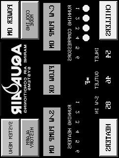
18 Starting the Chiller Unit in the Cooling Mode 1. Verify that the seacock supplying water to the Seawater Pump(s) is on and that the sea strainer is clear of debris. If there are any isolation valves be sure that they are in the proper position for the Seawater Pump that will be run. 2. Turn on the Control Circuit circuit breaker ( CCCB ). The touchscreen will now display the Main screen. 3. Turn on the System Pump circuit breaker ( SPCB ) 4. Turn on the Seawater Pump circuit Breaker (SWPCB) A B C D E F 5. Turn on the Compressor circuit breakers ( CCB# ) 6. Press the POWER button (A) until it displays POWER ON. 7. Press the Mode Switch (B) until it displays COOLING MODE. 8. The Chillwater Pump light (C) should illuminate and then the Flow Switch light (D) should read FLOW OK. 9. Press the CHILLERS button (E) to go to the Chiller Unit Screen. 10. On the Chiller Unit Screen Press the Compressor Switches (F) until they read ON for the number of compressors that you want to run I:\wordpfct\chiller start cool mode.wpd 3-1
.")
19 Starting the Chiller Unit in the Heating Mode Reverse Cycle Units Only 1. Verify that the seacock supplying water to the Seawater Pump(s) is on and that the sea strainer is clear of debris. If there are any isolation valves be sure that they are in the proper position for the Seawater Pump that will be run. 2. Turn on the Control Circuit circuit breaker ( CCCB ). The touchscreen will now display the Main screen. 3. Turn on the System Pump circuit breaker ( SPCB ) A B C D E F 4. Turn on the Seawater Pump circuit Breaker (SWPCB) 5. Turn on the Compressor circuit breakers ( CCB# ) 6. Press the POWER button (A) until it displays POWER ON. 7. Press the Mode Switch (B) until it displays HEATING MODE. 8. The Chillwater Pump light (C) should illuminate and then the Flow Switch light (D) should read FLOW OK. 9. Press the CHILLERS button (E) to go to the Chiller Unit Screen. 10. On the Chiller Unit Screen Press the Compressor Switches (F) until they read ON for the number of compressors that you want to run I:\wordpfct\chiller start rcheat mode.wpd 3-2
 3. Turn on the Immersion Heater circuit breakers ( HECB# ) A B C D 4. Press the POWER button (A) until it displays POWER ON. 5.")
20 Starting the Chiller Unit in the Heating Mode Immersion Heater Units Only 1. Turn on the Control Circuit circuit breaker ( CCCB ). The touchscreen will now display the Main screen. 2. Turn on the System Pump circuit breaker ( SPCB ) 3. Turn on the Immersion Heater circuit breakers ( HECB# ) A B C D 4. Press the POWER button (A) until it displays POWER ON. 5. Press the Mode Switch (B) until it displays HEATING MODE. 6. The Chillwater Pump light (C) should illuminate and then the Flow Switch light (D) should read FLOW OK. E 7. Press the HEATERS button (E) to go to the Heater Control Screen. F 8. On the Heater Control Screen Press the Heater Switches (F) until they read ON for the number of heater elements that you want to run I:\wordpfct\chiller start ihheat mode.wpd 3-3

21 Numeric Data Entry Screen On many of the screens there are Numeric Entry Keys used to enter a numeric variable. An example of this is entering a stage temperature or the number of compressors on a unit. When you press the key to enter a numeric variable the keypad shown below appears: A B D E F G H C On the right side of the screen the MINIMUM setting (D), MAXIMUM setting (E) and CURRENT setting (F) appear. To change the current setting enter the new number directly from the keypad (B). The new number will appear in the window (A) at the top. If you enter an incorrect number you can clear the entry by pressing the CLR key (C). You can then enter the correct number. After entering the correct number press the Enter key (G). If you do not want to make any changes to the current setting press the Cancel key (H) I:\wordpfct\numeric data entry screen.wpd 3-4
22 Alarm History and Alarm Count The first screen that appears (shown below) will show you the total alarms logged, the order in which they were logged, and the associated message. Press one of the buttons at the bottom of the screen to view more entries. Press LINE UP or LINE DOWN to select a particular alarm entry. Once an entry is highlighted, you may then press the DTLS button for more information about that entry (see below). Press the ALARM COUNT button to go to that screen (see below) Press CLEAR ALL to clear the history. Press EXIT to quit. ALARM HISTORY TOTAL OF 04 ALARMS ENTRY MESSAGE 01 LOW REFRIGERANT PRESSURE CHILLER 1 02 FLOW SWITCH FAULT 03 INVERTER FAULT 5 04 FREEZE THERMOSTAT FAULT 4 ALARM COUNT PAGE UP PAGE DOWN LINE UP LINE DOWN DTLS CLEAR ALL EXIT 3-5
23 The ALARM HISTORY DETAILS screen, shown below, provides information about the triggered alarm. Details include; when the alarm was triggered (ACTIVATED), the tag value that triggered the alarm (ACTUAL VALUE), and the set points (LOW LIMIT, HIGH LIMIT). The buttons allow you to EXIT, or switch to the previous (PREV) or NEXT entry. ALARM HISTORY DETAILS ENTRY NO. : 01 LOW REFRIGERANT PRESSURE CHILLER 1 ACTIVATED: 1:03: CLEARED: ACTUAL VALUE: 40 HIGH/LOW/DIS LOW LOW LIMIT: 40 HIGH LIMIT: 80 EXIT PREV NEXT The Alarm Count screen, shown below, shows you the number of times a particular alarm has been triggered (activated). From this screen you can clear a particular alarm count or you can clear them all. Use the buttons at the bottom of the screen, to move through the list, exit, clear alarms, or return to alarm history. ALARM COUNT ENTRY COUNT MESSAGE LOW REFRIGERANT PRESSURE CHILLER FLOW SWITCH FAULT INVERTER FAULT FREEZE THERMOSTAT FAULT 4 ALARM HISTORY PAGE UP PAGE DOWN LINE UP LINE DOWN CLEAR CLEAR ALL EXIT I:\wordpfct\alarm history and count.wpd 3-6
24 Cooling Settings Setting the Stage Cycling Temperatures The Stage Cycling Temperature is the temperature at which the compressor that is operating on that particular stage will cycle off. Press the STAGE CYCLING TEMPERATURES button. A numeric keypad will appear. Enter the stage temperature desired within the allowable range ( see Programmable Parameters sheet) and press ENTER. Setting the Cooling Differential The Cooling Differential is the number of degrees that the chillwater must warm up, after cycling off on the stage cycling temperature, before the compressor will restart. Press the COOLING DIFFERENTIAL button. A numeric keypad will appear. Enter the cooling differential desired within the allowable range ( see Programmable Parameters sheet) and press ENTER. Setting the Compressor Time Delay The Compressor Time Delay value is the delay, in seconds, between when a compressor is switched on ( or after a power outage) and the compressor actually starts. The value entered is multiplied by the number of each stage to get the time delay for that stage. An example is if the time delay value is set for 15 seconds. Compressor 1 will start after 15 seconds, compressor 2 after 30, compressor 3 after 45 seconds, etc. Press the COMPRESSOR TIME DELAY button. A numeric keypad will appear. Enter the time delay value desired within the allowable range ( see Programmable Parameters sheet) and press ENTER. Setting the Low Pressure Switch Time Delay The Low Pressure Switch Time Delay value is the delay, in seconds, between when the PLC detects a low refrigerant pressure condition and when the compressor is shut down because of the low refrigerant pressure condition. Press the LOW REFRIGERANT PRESSURE TIME DELAY button. A numeric keypad will appear. Enter the time delay value desired, within the allowable range ( see Programmable Parameters sheet), and press ENTER. 3-7
25 Transfer to the Main Screen Press the MAIN SCREEN button to go to the Main Screen. Transfer to the Settings Menu Press the SETTINGS MENU button to go to the Settings Menu. Transfer to the System Menu Press the SYSTEM MENU button to go to the System Menu. I:\wordpfct\plc\coolingsettings7.wpd 3-8

26 Heating Settings Setting the Stage Cycling Temperatures The Stage Cycling Temperature is the temperature at which the compressor (for reverse cycle units or immersion heater) that is operating on that particular stage will cycle off. Press the STAGE CYCLING TEMPERATURES button. A numeric keypad will appear. Enter the stage temperature desired within the allowable range ( see Programmable Parameters sheet) and press ENTER. Setting the Heating Differential The Heating Differential is the number of degrees that the chillwater must cool down, after cycling off on the stage cycling temperature, before the compressor ( or immersion heater) will restart. Press the HEATING DIFFERENTIAL button. A numeric keypad will appear. Enter the heating differential desired within the allowable range ( see Programmable Parameters sheet) and press ENTER. Setting the Heater Time Delay The Heater Time Delay value is the delay, in seconds, between when an immersion heater element is switched on ( or after a power outage) and the immersion heater element is actually energized. The value entered is multiplied by the number of each stage to get the time delay for that stage. An example is if the time delay value is set for 15 seconds. Immersion heater 1 will start after 15 seconds, immersion heater element 2 after 30, immersion heater element 3 after 45 seconds, etc. Press the HEATER TIME DELAY button. A numeric keypad will appear. Enter the time delay value desired within the allowable range ( see Programmable Parameters sheet) and press ENTER. 3-9
27 Transfer to the Main Screen Press the MAIN SCREEN button to go to the Main Screen. Transfer to the Settings Menu Press the SETTINGS MENU button to go to the Settings Menu. Transfer to the System Menu Press the SYSTEM MENU button to go to the System Menu. I:\wordpfct\plc\heatingsettings8.wpd 3-10
28 General Settings Setting the Number of Compressors Press the NUMBER OF COMPRESSORS button. A numeric keypad will appear. Enter a number 1-6 (equal to the number of compressors on the unit) and press ENTER. Setting the Number of Heaters Press the NUMBER OF HEATERS button. A numeric keypad will appear. Enter a number 1-6 (equal to the number of heaters on the unit) and press ENTER. The number of heaters refers to the number of heating stages that are located in the heater. Factory Settings Menu Press the F button to go to the Factory Settings menu. A numeric keypad will appear. Enter the pass code number and you will be transferred to the Factory Settings Menu. Setting the Temperature Display Type All of the temperature display inputs and outputs can be set to display in either Fahrenheit or Centigrade. Press the TEMPERATURE DISPLAY button. A numeric keypad will appear. Enter a 1 for Fahrenheit, 0 for Centigrade and press ENTER. If you are changing the system after it has been commissioned by the factory, you will need to go back and change all of the temperature input values to the new unit of measure. For example, if the system was originally set for Fahrenheit, you will have to change temperature inputs, such as the cycling temperatures, to the new Centigrade values. It is recommended, in this situation, that you use the Load Factory Default Settings to input the new values. Enabling the Inverter Option Setting this option equal to 1 tells the PLC that the system is equipped with inverters on the compressors. Press the INVERTERS button. A numeric keypad will appear. Enter a 1 to enable the option, 0 for standard across-the-line starters and then press ENTER. 3-11
29 Enabling the Inverter Speed Modulation Feature Setting this option equal to 1 tells the PLC that the system is equipped with an analog output card that is capable of controlling the speed of the Compressor Inverters. Press the INVERTER SPEED MODULATION button. A numeric keypad will appear. Enter a 1 to enable the option, 0 for standard operation and then press ENTER. Loading Factory Default Settings At any time during the life of the system you can reload the factory default settings in either Fahrenheit or Centigrade format. Values will be loaded in according to the Programmable Parameter factory default setting listing. Press the Load Factory Default Settings button. A numeric keypad will appear. Enter a 2 for a Fahrenheit system, 5 for a Centigrade system. Press ENTER to save the settings. All of the programmable parameters will now be updated. Cycle the Control Circuit circuit breaker once to save all of the settings. Enabling the Pressure Transducer Option Setting this option equal to 1 tells the PLC that the system is equipped with refrigerant pressure transducers on the compressors. Press the PRESSURE TRANSDUCERS button. A numeric keypad will appear. Enter a 1 to enable the option, 0 for none and then press ENTER. With this option enabled the refrigerant suction and discharge pressures will be displayed on the Refrigerant pressures screen (14). Transfer to the Main Screen Press the MAIN SCREEN button to go to the Main Screen. Transfer to the Settings Menu Press the SETTINGS MENU button to go to the Settings Menu. Transfer to the System Menu Press the SYSTEM MENU button to go to the System Menu. Transfer to the Time and Contrast Menu Press the TIME & CONTRAST button to go to the Time & Contrast Menu. I:\wordpfct\plc\generalsettings6.wpd 3-12
30 Pump Settings Setting the Number of Seawater Pumps Press the SEAWATER PUMP QUANTITY button. A numeric keypad will appear. Enter 1 or 2 and press ENTER. Selecting Seawater Pump 1 or 2 The SWP 1 or 2 button, used to select either Seawater Pump 1 or 2, will only appear if the Seawater Pump quantity is set for 2. Press the SWP 1 or 2 button. A numeric keypad will appear. Enter a 1 or 2 and press ENTER. Setting the Number of Chillwater Pumps Press the CHILLWATER PUMP QUANTITY button. A numeric keypad will appear. Enter 1 or 2 and press ENTER. Selecting Chillwater Pump 1 or 2 The CWP 1 or 2 button, used to select either Chillwater Pump 1 or 2, will only appear if the Chillwater Pump quantity is set for 2. Press the CWP 1 or 2 button. A numeric keypad will appear. Enter a 1 or 2 and press ENTER. Setting the Seawater Pump Mode The seawater pump can be set to run constantly (MANUAL = 0) or to cycle with the compressors (AUTO = 1). Press the SEAWATER PUMP MODE button. A numeric keypad will appear. Enter a 1 for AUTO or 0 for MANUAL and press ENTER. Enable Seawater Pump VFD ( Variable Frequency Drive ) option If the system is equipped with a seawater pump VFD this option must be set. Press the SEAWATER PUMP VFD button. A numeric keypad will appear. Select 1 to enable this feature, 0 to disable this feature. 3-13
31 Transfer to the Seawater Pump VFD Settings Screen Press the S/W PUMP VFD SETTINGS button Transfer to the Pump Hour Meter Screen Press the PUMP HOUR METER button Transfer to the Settings Menu Screen Press the SETTINGS MENU button I:\wordpfct\plc\pumpsettings5.wpd 3-14

32 Alternating Sequence Settings The purpose of the Alternating Sequence Setting Screen is to display current settings and to allow you to modify certain sequence parameters. The alternating sequences are all based upon the running time of the system. The system will rotate the sequence one position after the alternating period has elapsed. The amount of time remaining is always displayed in the TIME REMAINING, HOURS display. When the sequence changes it always moves ahead by one position. An example of this is a four compressor unit: Lead Compressor Running Order The current alternating sequence is displayed in the CURRENT ALTERNATING SEQUENCE window. Changing the Alternating Sequence Mode The system can be set to automatically rotate the cycling sequence of the compressors according to the time period set in the Alternating Period ( Auto ) or it can be held in one sequence (Manual). Press the ALTERNATING SEQUENCE button. A numeric keypad will appear. Enter a 1 for Auto rotation or a 0 for manual rotation. Press ENTER to save. Changing the Alternating Period, Hours This setting determines how often the system rotates the compressor sequence. Press the ALTERNATING PERIOD, HOURS button. A numeric keypad will appear. Enter the time, in hours and tenth s of an hour, that you want the system to change. If you wanted it to rotate every 24 hours enter 24.0 using the numeric keypad. Press ENTER to save. 3-15
33 Changing the Current Lead Compressor You can, at any time, change the lead compressor. Press the CURRENT LEAD COMPRESSOR button. A numerical keypad will appear. Enter the number of the compressor you want to be on stage one and press ENTER to save. Transfer to the Main Screen Press the MAIN SCREEN button to go to the Main Screen. Transfer to the System Menu Press the SYSTEM MENU button to go to the System Menu. Transfer to the Settings Menu Press the SETTINGS MENU button to go to the Settings Menu. I:\wordpfct\plc\altsequencescreen15.wpd 3-16
.")
34 System Time, Date and Screen Contrast Settings The purpose of this screen is to allow you to change the system time and date as necessary. Correct time and date settings are necessary as they are used to log faults in the alarm window. The time is stored in military format ( 2:30 in the afternoon is displayed as 14:30 hours). All settings for the time ( hours and minutes ) and date (day, month and year) must be updated all at once. Therefore, correct entries must be made in all five windows before the PRESS TO UPDATE TIME & DATE button is pushed. Once this button is pushed the current time and date will appear in the CURRENT TIME window. The contrast setting changes the appearance of the LCD screen in different light conditions. Changing the Hour Setting Press the HOUR button. A numeric keypad appears. Enter the correct hour(0-23) and press ENTER to save. Changing the Minutes Setting Press the MINUTES button. A numeric keypad appears. Enter the correct minutes (0-59) and press ENTER to save. Changing the Day Setting Press the DAY button. A numeric keypad appears. Enter the correct day (0-31) and press ENTER to save. Changing the Month Setting Press the MONTH button. A numeric keypad appears. Enter the correct month (1-12) and press ENTER to save. 3-17
35 Changing the Year Setting Press the YEAR button. A numeric keypad appears. Enter the correct year (last two digits only-for example 2002 would be entered as 02) and press ENTER to save. Changing the Contrast Press the CONTRAST up arrow to increase the contrast or the down arrow to decrease the contrast Transfer to the Main Screen Press the MAIN SCREEN button to go to the Main Screen. Transfer to the General Settings Menu Press the GENERAL SETTINGS button to go to the General Settings Menu. I:\wordpfct\plc\timedatecontrastscreen16.wpd 3-18


36 Chiller, Heater and Pump Hour Meter Display & Reset Resetting the Hour Meters To zero out the hour meter indicator, press the RST button below the indicator. The value will now go to zero. Transfer to the Main Screen Press the MAIN SCREEN button to go to the Main Screen. Transfer to the System Menu Press the SYSTEM MENU button to go to the System Menu. Transfer to the Chiller Control Screen Press the CHILLER CONTROL button Transfer to the Heater Control Screen Press the HEATER CONTROL button Transfer to the Pump Settings Screen Press the PUMP SETTINGS button I:\wordpfct\plc\hourmeterreset wpd 3-19


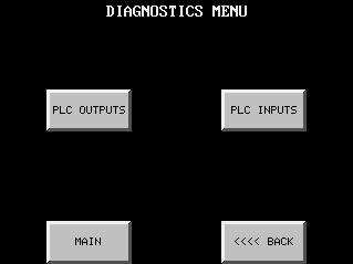
37 PLC Outputs Screen The purpose of this screen is to allow you to manually energize any of the PLC outputs. These can be used at any time during the operation of the unit. The switch is a momentary contact. This means that the output will only stay energized as long as you are pressing the button. Returning to the Factory Settings Menu Press the <<<<BACK button. PLC Inputs Screen The purpose of this screen is to display the status of all of the PLC inputs. If the indicator is green the input is receiving a signal. Returning to the Factory Settings Menu Press the <<<<BACK button. I:\wordpfct\plc\plcoutputsinputs26-27.wpd 3-20

38 Refrigerant Pressures Screen The purpose of the Refrigerant Display screen is to display the refrigerant suction and discharge pressures for each compressor. This display is an option and will only be visible if the Refrigerant Pressure Transducer option has been selected. Suction pressures are displayed on the left, discharge pressures are on the right. The light in the center indicates whether or not the pressures are being actively read by the PLC. Incoming Seawater and Chillwater temperatures are displayed for troubleshooting purposes. Transfer to the Main Screen Press the MAIN SCREEN button to go to the Main Screen. Transfer to the System Menu Press the SYSTEM MENU button to go to the System Menu. Transfer to the Chiller Control Screen Press the CHILLER CONTROL button to go to the Chiller Control Screen. I:\wordpfct\plc\refrigerant pressures screen14.wpd 3-21
.")
39 Seawater Pump VFD Settings This screen controls the voltage/frequency output of the seawater pump VFD. This screen is only visible if the unit is equipped with the optional seawater pump VFD. Setting the Maximum Speed Temperature This is the temperature that the seawater pump will begin to run at maximum speed in the cooling mode ( the opposite will occur in the reverse cycle mode ). To set the temperature press the MAXIMUM SPEED button. A numeric keypad will appear. Enter the temperature and press ENTER. Setting the Maximum Speed % This is maximum speed ( as a percentage of total overall speed ) that the pump will be running at when the water temperature reaches the Maximum Speed Temperature. Press the MAXIMUM SPEED % button. A numeric keypad will appear. Enter the speed percentage and press ENTER. Setting the Minimum Speed Temperature This is the temperature that the seawater pump will begin to run at minimum speed in the cooling mode ( the opposite will occur in the reverse cycle mode ). To set the temperature press the MINIMUM SPEED button. A numeric keypad will appear. Enter the temperature and press ENTER. Setting the Minimum Speed % This is minimum speed ( as a percentage of total overall speed ) that the pump will be running at when the water temperature reaches the Minimum Speed Temperature. Press the MINIMUM SPEED % button. A numeric keypad will appear. Enter the speed percentage and press ENTER. 3-22
40 Transfer to the Main Screen Press the MAIN SCREEN button to go to the Main Screen. Transfer to the Pump Settings Screen Press the PUMP SETTINGS button. Transfer to the Chiller Control Screen Press the CHILLERS button. Operation of Seawater Pump VFD in Cooling and Heating (Reverse Cycle) Mode I:\wordpfct\plc\swpvfdsettingssettings11.wpd 3-23

41 Compressor Inverter Modulation Settings This screen controls the voltage/frequency output of the compressor inverters based on the current set points and water temperatures. This screen is only visible if the unit is equipped with the optional Compressor Inverter Modulation feature. Setting the Number of Degrees Above/Below Setpoint This setting determines the temperature at which the compressor inverter begins to modulate the speed of the compressor. EXAMPLE: If the compressor stage cooling setpoint is 45 F and the Number of Degrees Above/Below Setpoint is set for 8 degrees, the inverter will begin to modulate the speed of the compressor at 53 F (45 F + 8 = 53 F) return water temperature. If the compressor stage heating setpoint is 120 F and the Number of Degrees Above/Below Setpoint is set for 8 degrees, the inverter will begin to modulate the speed of the compressor at 112 F (120 F - 8 = 112 F) return water temperature. To set the temperature press the DEGREES ABOVE/BELOW SETPOINT WHERE MODULATION STARTS button. A numeric keypad will appear. Enter the temperature and press ENTER. Setting the Minimum VFD Output Frequency, HZ This setting determines the lowest output frequency that the inverters will ramp down to while they are modulating. To set the minimum frequency press the MINIMUM VFD OUTPUT FREQUENCY, HZ button. A numeric keypad will appear. Enter the frequency (which must be between the minimum and maximum values) and press ENTER. 3-24
42 When the stage that is currently operating reaches the Ramp Down Starting Temperature the text on the left will change from FULL SPEED # (where # is the stage number) to MODULATING #. This indicates that the inverter is now beginning to decrease the speed of the compressor. This will also show in the Inverter Frequency, HZ window to the right where you will see the frequency begin to change from 60. Transfer to the Main Screen Press the MAIN SCREEN button to go to the Main Screen. Transfer to the Chiller Control Screen Press the CHILLERS button. Transfer to the System Menu Screen Press the SYSTEM MENU button. I:\wordpfct\plc\CompInvModSettings.wpd 3-27
43 Programmable Parameters 4
44 Programmable Parameters Fahrenheit & Centigrade Systems No. PARAMETER DESCRIPTION RANGE FACTORY SETTING SCREEN NUMBER MEMORY LOCATION 1 Number of compressors 2-6 PLC-3 = 3 PLC-6 = 6 6 V Number of Immersion Heater stages V Compressor time delay staging s 7 V Heater time delay staging s 8 V Alternating Sequence Mode 0 = manual 1 = auto 1 15 V Lead compressor in alternating sequence V Compressor alternating sequence CTA4 8 Alternating period, hours V Seawater Pump running mode 0 = manual 1 = auto 1 5 V Chillwater Pump quantity V Chillwater Pump Selected V Seawater Pump quantity V Seawater Pump Selected V Compressors are Variable Frequency Drive (VFD) controlled 0 = No 1 = Yes 1 6 V Seawater pump is Variable Frequency Drive (VFD) controlled 0 = No 1 = Yes 0 5 V Maximum Seawater Pump VFD speed 0-100% V Minimum Seawater Pump VFD speed 0-100% V Low Refrigerant Pressure switch time delay 0-300s 30s 7 V Refrigerant pressure transducers on unit 0 = No 1 = Yes 0 6 V2107 I:\wordpfct\programmable parameters 1-1.wpd 4-1
45 Programmable Parameters Fahrenheit or Centigrade Systems No. PARAMETER DESCRIPTION RANGE FACTORY SETTING F = 2 C = 5 SCREEN NUMBER MEMORY LOCATION 50 Load Factory Defaults 51 Temperature display 2 = F/ 5 = C/ 1 = F/ 0 = C/ V V Cooling Stage 1 set point V Cooling Stage 2 set point V Cooling Stage 3 set point V Cooling Stage 4 set point V Cooling Stage 5 set point V Cooling Stage 6 set point V Cooling differential V Heating Stage 1 set point V Heating Stage 2 set point V Heating Stage 3 set point V Heating Stage 4 set point V Heating Stage 5 set point V Heating Stage 6 set point V Heating differential V Temperature at which the seawater pump VFD will be operating at maximum speed Temperature at which the seawater pump VFD will be operating at minimum speed Activate the compressor inverter speed modulation feature Number of degrees above/below setpoint that the inverters will begin to modulate the speed of the compressors V V V V Minimum Inverter Frequency, Hz V1540 I:\wordpfct\programmable parameters 1-1.wpd 4-2
46 Factory Programmable Parameters These parameters are only adjustable by Factory authorized personnel No. PARAMETER DESCRIPTION RANGE FACTORY SETTING SCREEN NUMBER MEMORY LOCATION 100 PLC Type 101 Heating Method PLC-3 = 3 PLC-6 = 6 0 = None 1 = Reverse Cycle 2 = Immersion Heat N/A 19 V2106 N/A 19 V Main flow switch time delay s 22 V Heating flow switch time delay s 22 V General alarm muting time delay s 22 V Temperature display muting time delay s 22 V Reversing valve time delay at startup s 22 V Anti-short cycle timer for compressors 0-300s 120s 22 V Compressor Hour Meter N/A 18 V Compressor Hour Meter N/A 18 V Compressor Hour Meter N/A 18 V Compressor Hour Meter N/A 18 V Compressor Hour Meter N/A 18 V Compressor Hour Meter N/A 18 V Heater Hour Meter N/A 18 V Heater Hour Meter N/A 18 V Heater Hour Meter N/A 18 V Heater Hour Meter N/A 18 V Heater Hour Meter N/A 18 V Heater Hour Meter N/A 18 V Seawater Pump Hour Meter N/A 20 V Seawater Pump Hour Meter N/A 20 V Chillwater Pump Hour Meter N/A 20 V Chillwater Pump Hour Meter N/A 20 V1672 I:\wordpfct\programmable parameters 1-1.wpd 4-3
47 System Operation Diagrams 5
48 5-1 I:\wordpfct\plc\plcops.wpd
49 5-2
50 5-3
51 5-4
52 5-5
53 5-6
54 5-7 I:\WORDPFCT\PLC\PLCOPS.WPD
55 Typical Wiring Schematics 6
56 TYPICAL PLC SYSTEM WIRING SCHEMATIC FOR UP TO THREE 2-5 TON CHILLERS 6-1
57 6-2
58 6-3 I:\WORDPFCT\PLC\PLC-3 SYSTEM.WPD
59 TYPICAL PLC SYSTEM WIRING SCHEMATIC FOR UP TO SIX 2-5 TON CHILLERS 6-4
60 6-5
61 6-6
62 6-7 I:\WORDPFCT\PLC\PLC-6 SYSTEM.WPD
63 Digital Input Cards P-D2-08ND3 DIGITAL INPUT 8 POINT 24 VDC P-D2-16ND3-2 DIGITAL INPUT 16 POINT 24 VDC 6-8
64 P-D2-32ND3 DIGITAL INPUT 32 POINT 24 VDC P-ZL-CM40 40 POSITION WIRING INTERFACE CONNECTOR MODULE CONNECTED VIA P-ZL-4CBL4 CABLE TO P-D2-32ND3 CARD 6-9
65 Analog Input Cards P-F2-04AD-1 ANALOG INPUT 4-20 ma 4 CHANNEL P-F2-08AD-1 ANALOG INPUT 4-20mA 8 CHANNEL 6-10
66 Relay Output Cards P-D2-08TR RELAY OUTPUT 8 POINT P-D2-12TR RELAY OUTPUT 12 POINT 6-11
67 Analog Output Cards P-F2-02DA-1 ANALOG OUTPUT 4-20mA 2 CHANNEL P-F2-08DA-1 ANALOG OUTPUT 4-20mA 8 CHANNEL I:\WORDPFCT\PLC\PLC-CARD SCHEMATICS.WPD 6-12
68 Component Troubleshooting 7
69 PLC Power Supply and CPU Troubleshooting CPU Indicators The DL250 CPU has indicators ( Status LED s ) on the front to help you diagnose problems with the system. The table below gives a quick reference of potential problems associated with each status indicator. Following the table will be a more detailed analysis of each of the indicator problems. Indicator Status Potential Problems PWR off 1. Insufficient control circuit voltage to the Power Supply 2. Power Supply / CPU is faulty 3. Other component such as an I/O module has power supply shorted RUN off 1. CPU programming error 2. Mode switch in STOP position CPU on 1. Electrical noise interference 2. CPU defective BATT on 1. CPU battery low 2. CPU battery missing or disconnected 7-1
70 PWR Indicator There are three general reasons for the CPU power status LED ( PWR ) to be OFF: 1. Power to the Power Supply is incorrect or is not applied If the voltage to the Power Supply is not correct, the CPU and/or base may not operate properly or may not operate at all. Use the following guidelines to correct the problem. Disconnect the control circuit power and check all incoming wiring for loose connections. If all of the connections are tight, reconnect the control circuit power and measure the voltage at the power supply terminal strip to insure that it is within specifications. If the voltage is not correct shut the system down and correct the problem. If all wiring is properly connected and the incoming power is within specifications required, the base power supply should be returned for repair. 2. The CPU is faulty There is not a good check to test for a faulty CPU other than substituting a known good one to see if this corrects the problem. If you have experienced major power surges, it is possible the CPU and power supply have been damaged. 3. Other component(s) have the power supply shut down It is possible a faulty module or external device using the system 5V can shut down the power supply. This 5V can be coming from the base or from the CPU communication ports. To test for an external device causing the problem: Turn off the power to the Power Supply Disconnect all external devices (i.e. communications cables) from the CPU Reapply power to the system If the power supply operates normally you may have either a shorted device or a shorted cable. If the power supply does not operate normally then test for an I/O module causing the problem by following the steps below: Turn off the power to the Power Supply Remove a module from the base Reapply power to the power supply Continue doing this, one module at a time until the PWR LED operates normally or you run out of modules. Bent base connector pins on the module can cause this problem. Verify that the connector is not the problem 7-2
71 RUN Indicator If the CPU will not enter the Run mode ( the RUN indicator is off), the problem is usually program related unless the CPU has a fatal error. The Mode Switch must be in the TERM (Terminal) position at all times because of the touchscreen. CPU Indicator If the CPU indicator is on, a fatal error has occurred in the CPU. Generally, this is not a programming problem but an actual hardware failure. You can try power cycling the system to clear the error. If the error clears, monitor the system and determine what caused the problem. If power cycling the system does not correct the problem or if the problem returns, you should replace the CPU. I:\wordpfct\plc\power supply&cpu-ts.wpd 7-3
72 Touchscreen Troubleshooting If the touchscreen will not power up Verify that the wires from the DC power supply are tightly connected to the 24 VDC + and - connections on the back of the screen. 2. Verify that there is 24 VDC at the 24 VDC + and - connections on the back of the touchscreen. 3. If the Operation LED does not light it means there is either no power to the touchscreen or the internal power supply has failed. Check the power source or replace panel. 4. If the LED turns RED and stays RED it means the touchscreen has failed and the panel must be replaced. 5. If the LED flashes RED and then turns GREEN this indicates normal operation. If the display does not light after 10 seconds see Blank Display section below. If the display lights, operation is normal. If the display is blank Display indicates NO SCREEN for 3 seconds after power-up. There is no program installed. 2. Push the extreme upper left and lower left corners of the touchscreen. If there is no change and the screen remains blank, replace the panel. If the SETUP screen appears and the screen is hard to read, adjust the contrast. If the SETUP screen appears normal, there is no program installed. i:\wordpfct\plc\ tstroubleshooting.wpd 7-4
73 Touchscreen Setup Screen After the touchscreen is powered up, you may enter the Setup Mode by pressing the upper left and lower left touch cells on the panel screen. The following screen is displayed: Revision Firmware A.4 Boot A.7 Hardware A Memory Used Free Total Flash 0 Clock 8:56:08 28-SEP-02 COM1 Computer Contrast 98 Part # EZ-S6C-K Clock COM1 Contrast Touchpad Test Display Test Exit Information is displayed in the upper left hand corner about the current revision of the Firmware, Hardware and Boot program. Also shown is the amount of RAM memory - Used, Free and Total, and Flash Memory. Below that is displayed the time and date, whether the COM1 port is connected to a computer or a printer, and the current Contrast Setting. There are six buttons at the bottom of the screen. They are labeled Clock, COM1, Contrast, Touchpad Test and Exit. DO NOT USE THE CONTRAST, CLOCK OR COM1 BUTTONS! The COM1 setting will never change and the clock and contrast settings are accessed from screen 16 ( Time, Date and Contrast ). 7-5
74 Touchpad Cell Test Screen Shown above is the Touchpad Cell Test Screen. There are 48 touch cells total ( 6x8 ). Each touch cell is numbered for reference. Press on each or any square to test that the cell is operating. It will beep and be highlighted after pressing to show that it has been tested. Press the cell again to deselect it. Press Exit in the lower right hand corner to quit. Touchpad Display Test The Display Test button is primarily used for production testing at the factory. Bands scroll horizontally and vertically across the screen during this test. It is used to check the pixel quality of the display before shipping the unit. Exit Button Press the Exit button to return to the Main Screen at any time. I:\wordpfct\plc\tssetupscreen.wpd 7-6
75 External Power Supply Troubleshooting i:\wordpfct\plc\222710ts.wpd 7-7
76 Temperature & Pressure 4-20 ma Transducer Troubleshooting Temperature Transducer Pressure Transducer I:\wordpfct\plc\transducer-ts.wpd 7-8
77 PLC Alarm Code Listing ALARM # ALARM CODE ALARM DESCRIPTION 1 ERROR CODE VALUE ERROR CODE VALUE 2 PLC ERROR PLC ERROR 3 PUMP STARTER FAULT PUMP STARTER OVERLOAD FAULT 4 C/W FLOW FAULT FLOW SWITCH FAULT 5 H/W FLOW FAULT HOT WATER CIRCUIT FLOW SWITCH FLT 6 FRZ FAULT 1 FREEZE THERMOSTAT FAULT 1 7 FRZ FAULT 2 FREEZE THERMOSTAT FAULT 2 8 FRZ FAULT 3 FREEZE THERMOSTAT FAULT 3 9 FRZ FAULT 4 FREEZE THERMOSTAT FAULT 4 10 FRZ FAULT 5 FREEZE THERMOSTAT FAULT 5 11 FRZ FAULT 6 FREEZE THERMOSTAT FAULT 6 12 INV FAULT 1 INVERTER FAULT 1 13 INV FAULT 2 INVERTER FAULT 2 14 INV FAULT 3 INVERTER FAULT 3 15 INV FAULT 4 INVERTER FAULT 4 16 INV FAULT 5 INVERTER FAULT 5 17 INV FAULT 6 INVERTER FAULT 6 18 LPS1 FAULT LOW REFRIGERANT PRESSURE CHILLER 1 19 LPS2 FAULT LOW REFRIGERANT PRESSURE CHILLER 2 20 LPS3 FAULT LOW REFRIGERANT PRESSURE CHILLER 3 21 LPS4 FAULT LOW REFRIGERANT PRESSURE CHILLER 4 22 LPS5 FAULT LOW REFRIGERANT PRESSURE CHILLER 5 23 LPS6 FAULT LOW REFRIGERANT PRESSURE CHILLER 6 24 HPS1 FAULT HIGH REFRIGERANT PRESS. CHILLER 1 25 HPS2 FAULT HIGH REFRIGERANT PRESS. CHILLER 2 26 HPS3 FAULT HIGH REFRIGERANT PRESS. CHILLER 3 27 HPS4 FAULT HIGH REFRIGERANT PRESS. CHILLER 4 28 HPS5 FAULT HIGH REFRIGERANT PRESS. CHILLER 5 29 HPS6 FAULT HIGH REFRIGERANT PRESS. CHILLER 6 30 CTO1 FAULT COMPRESSOR STARTER OVERLOAD 1 31 CTO2 FAULT COMPRESSOR STARTER OVERLOAD 2 32 CTO3 FAULT COMPRESSOR STARTER OVERLOAD 3 33 CTO4 FAULT COMPRESSOR STARTER OVERLOAD 4 34 CTO5 FAULT COMPRESSOR STARTER OVERLOAD 5 35 CTO6 FAULT COMPRESSOR STARTER OVERLOAD 6 36 HTT FAULT HIGH TEMP THERMOSTAT FAULT 7-9
78 ALARM # ALARM CODE ALARM DESCRIPTION 37 FORCED RUN MODE PLC CPU IS IN RUN MODE 38 FORCED STOP MODE PLC CPU IS IN STOP MODE 39 CRITICAL ERROR PLC CPU CRITICAL ERROR 40 BATTERY LOW PLC CPU BATTERY LOW 41 PROGRAM MEMORY ERROR PLC CPU PROGRAM MEMORY ERROR 42 I/O ERROR PLC I/O ERROR 43 COMMUNICATIONS ERROR PLC CPU COMMUNICATIONS ERROR 44 COMPRESSOR OVERLOAD 1 COMPRESSOR OVERLOAD 1 45 COMPRESSOR OVERLOAD 2 COMPRESSOR OVERLOAD 2 46 COMPRESSOR OVERLOAD 3 COMPRESSOR OVERLOAD 3 47 COMPRESSOR OVERLOAD 4 COMPRESSOR OVERLOAD 4 48 COMPRESSOR OVERLOAD 5 COMPRESSOR OVERLOAD 5 49 COMPRESSOR OVERLOAD 6 COMPRESSOR OVERLOAD 6 50 OIL PRESSURE FAULT 1 OIL PRESSURE FAULT 1 51 OIL PRESSURE FAULT 2 OIL PRESSURE FAULT 2 52 OIL PRESSURE FAULT 3 OIL PRESSURE FAULT 3 53 OIL PRESSURE FAULT 4 OIL PRESSURE FAULT 4 54 OIL PRESSURE FAULT 5 OIL PRESSURE FAULT 5 55 OIL PRESSURE FAULT 6 OIL PRESSURE FAULT 6 I:\WordPfct\PLC\PLC-Alarm Listing.wpd 7-10
TWLC - Tempered Water Logic Controller. The Intelligent Control
 TWLC - Tempered Water Logic Controller The Intelligent Control Chiller Controls Features: Up to six (6) stages: individual board for each stage maximizes redundancy. Menu driven access and programming.
User s Manual. TIGER S EYE E-Series Mark V Jockey. TIGERFLOW Systems, Inc Mint Way Dallas, Texas
 User s Manual TIGER S EYE E-Series Mark V Jockey TIGERFLOW Systems, Inc. 4034 Mint Way Dallas, Texas 75237 214-337-8780 www.tigerflow.com TABLE OF CONTENTS Introduction... 4 Sequence of Operation... 5
Refrigeration Controller Operator s Manual (HRC) PO Box 6183 Kennewick, WA
 PO Box 6183 Kennewick, WA") Refrigeration Controller Operator s Manual (HRC) PO Box 6183 Kennewick, WA 99336 www.jmcvr.com 1-509-586-9893 Table of Contents TABLE OF FIGURES...1 OVERVIEW OF THE HRC CAPABILITIES...2 INSTALLATION AND
Refrigeration Controller Operator s Manual (HRC) PO Box 6183 Kennewick, WA 99336 www.jmcvr.com 1-509-586-9893 Table of Contents TABLE OF FIGURES...1 OVERVIEW OF THE HRC CAPABILITIES...2 INSTALLATION AND
Tempered Water Logic Control OPERATION l TROUBLE SHOOTING
 Tempered Water Logic Control OPERATION l TROUBLE SHOOTING English For MPE Multiple Chiller Units Control Panel TEMPERED WATER SYSTEMS L-2199 Rev. 20080223 Revision: L-2199 20101104 *** IMPORTANT NOTICE
ModSync Sequencing System Installation & Operation Manual. For use with Fulton Steam Boilers.
 ModSync Sequencing System Installation & Operation Manual For use with Fulton Steam Boilers. Revision 3.0 8/21/2008 - 2 - Table of Contents Introduction Page 4 Features Page 4 Sequence of Operation Page
OPERATING MANUAL Enertronic Control System 2
 OPERATING MANUAL Enertronic Control System 2 The integrated control system for Lennox chillers in the Ecologic range Manufacturer: Lennox Benelux B.V. Postbus 1028, 3860 BA NIJKERK Watergoorweg 87, 3861
MPT Electric Fire Pump Controller
 MPT Electric Fire Pump Controller Alarm Messages and Guide This manual provides alarm descriptions, troubleshooting steps, and alarm set point configuration information for Metron MPT Fire Pump Controllers
MYRIAD TRIPLEX PUMP CONTROLLER INSTRUCTION MANUAL
 MYRIAD TRIPLEX PUMP CONTROLLER INSTRUCTION MANUAL MYRIAD TPC VISIT OUR WEBSITE SIGMACONTROLS.COM MYRIADI&O062705 2 TABLE OF CONTENTS INTRODUCTION 3 Ordering Information Specifications Features WIRING 7,8
Safety & Installation Instructions
 Model 8800 Universal Communicating Thermostat Safety & Installation Instructions READ AND SAVE THESE INSTRUCTIONS Table of contents Installation Installation location recommendations... 2 Thermostat mounting...
Dryer Controller M720
 User Manual Dryer Controller M720 Hardware version 2.00 Software version 2.00 Manual M720 Dryer controller Page 1 of 60 Document history Preliminary version: - Created in April, 2009 Hardware Version 2.00,
OPERATING MANUAL Enertronic Control System 2
 OPERATING MANUAL Enertronic Control System 2 The integrated control system for Lennox chillers in the Ecologic and Seconscrew ranges Manufacturer Lennox Benelux B.V. Postbus 1028, 3860 BA NIJKERK Watergoorweg
User Manual. Dryer Controller M720
 User Manual Dryer Controller M720 Hardware version 1.00 Software version 1.00 Preliminary version Manual M720 Dryer controller Page 1 of 42 Document history Preliminary version: - Created in April, 2009
Tri-Stack Smart System
 Tri-Stack Smart System TM Notes & Warnings - The protection provided by this equipment may be impaired if it is not used in the manner specified herein. - Ensure all wiring meets applicable national and
EasyTronic III MANUAL SERVICE
 rev.6 EasyTronic III MANUAL SERVICE General characteristics: Power supply 24 Vac ±15% Max consumption at 24Vac 300mA Relay outputs 6 Maximum relay current 8 A res. Serial standard RS232 2 Serial standard
Lift Station Level Controller
 Lift Station Level Controller Installation and Operation Manual 1 California Motor Controls, Inc. Benicia, CA Table of Contents 1. Features Product Overview... 4-6 Access Security... 7 Optional Features...
RPM1600 Series Room Pressure Monitors
 RPM1600 Series Room Pressure Monitors Technical Bulletin LB-RPM1611-0, LB--0 Code No. LIT-12012228 Issued October 2017 Refer to the QuickLIT website for the most up-to-date version of this document. How
Electro-Sentry. Users Manual
 Electro-Sentry Users Manual 2. To view an individual point, e.g. Speed just touch that point and it will display a graph showing the 45 min. of activity. Viewing a Leg: 1. Touch the desired leg, e.g. East
Replaceable LED modules. Sleep or unattended mode. Auto-silence and auto-acknowledge
 Replaceable LED modules 11 Alarm Sequences as per ISA-18.1 standard Each channel/window fully field programmable RS232 or RS485 MODBUS-RTU communication Repeat relay for each window and multifunction relays
Installation Instructions / User s Manual TSTAT0406 and TSTAT0408
 997-060180-5 Installation Instructions / User s Manual TSTAT0406 and TSTAT0408 4 HEAT 2 COOL DUAL FUEL TSTAT0406 & TSTAT0408-4 WIRE CAPABLE THERMOSTAT (NAXA00201DB Daughter Board sold separately) LEFT
CommStat 4. Controller for Redundant Telecom HVAC Systems PRODUCT DATA SHEET. Features and Benefits
 CommStat 4 PRODUCT DATA SHEET Controller for Redundant Telecom HVAC Systems General Description The CommStat 4 is an HVAC controller designed specifically for controlling two redundant air conditioners,
Pump-Down Controller MODEL 4052
 Pump-Down Controller 4-20mA Input/Scalable Output Seal Fail Monitoring Duplex Pump Alternation Hand-Off-Auto Controls Dual Run-time Meters RS-485/Modbus Communications DESCRIPTION The Model 4052 Pump-Down
OPERATING INSTRUCTIONS
 COMFORT CONTROL CENTER 2 THERMOSTAT OPERATING INSTRUCTIONS PROGRAMMABLE THERMOSTAT MODEL 3314080.000 BLACK 3314080.015 WHITE USA SERVICE OFFICE Dometic Corporation 1120 North Main Street Elkhart, IN 46514
Spa Touch Control Panel with BP2100, BP6013 spa controllers. (Spa Owner s Manual insert)
") Spa Touch Control Panel with BP2100, BP6013 spa controllers. (Spa Owner s Manual insert) P.N. 7876C (export) February 12, 2015 For Spas equipped with BP2100, BP6013 controllers and Spa Touch panel. Spa
Spa Touch Control Panel with BP2100, BP6013 spa controllers. (Spa Owner s Manual insert) P.N. 7876C (export) February 12, 2015 For Spas equipped with BP2100, BP6013 controllers and Spa Touch panel. Spa
GG-2 2-CHANNEL GAS DETECTION CONTROL PANEL. Installation and Operation Manual
 GG-2 2-CHANNEL GAS DETECTION CONTROL PANEL Installation and Operation Manual 2 GG-2 Warning Use this product only in the manner described in this manual. If the equipment is used in a manner not specified
Dryer Master DM510 Commissioning Guide
 COMMISSIONING GUIDE Dryer Master DM510 Dryer Moisture Systems Inc. 640 Superior Drive Waterloo, Ontario Phone 519.725.4700 Fax 519.885.4300 USA & Canada Toll Free 1-888-318-0009 E-mail: info@dryermaster.com
Spa Touch Control Panel with 2000, 2100 controllers. (Spa Owner s Manual insert)
") Spa Touch Control Panel with 2000, 2100 controllers (Spa Owner s Manual insert) P.N. 7876B February 11, 2015 For Spas equipped with BP2000, BP2100 controllers and Spa Touch panel. Spa Touch Control Panel
Spa Touch Control Panel with 2000, 2100 controllers (Spa Owner s Manual insert) P.N. 7876B February 11, 2015 For Spas equipped with BP2000, BP2100 controllers and Spa Touch panel. Spa Touch Control Panel
Rooftop Thermostat Controller Specification and Installation Instructions. Model TRT2422
 ºF / º C Rooftop Thermostat Controller Model TRT2422 Description The TRT2422 is a combination controller and thermostat with a built-in scheduler, which is designed for simple and accurate control of single
Aqua-Air Tempwise 2001 Chillwater Digital Thermostat. Operating Manual. Aqua-Air Manufacturing division of the James D. Nall Co., Inc.
 Aqua-Air Tempwise 2001 Chillwater Digital Thermostat Operating Manual Aqua-Air Manufacturing division of the James D. Nall Co., Inc. 1050 East 9th Street Hialeah, FL 33010 U.S.A. Phone (305) 884-8363 Fax
1025, BOUL. MARCEL-LAURIN INSTRUCTION MANUAL FOR WATER COOLED ENVIROCHILL CHILLER. Prepared par Claude Gadoury, P. Eng MTL TECHNOLOGIES INC.
 WYETH-AYERST CANADA INC. 1025, BOUL. MARCEL-LAURIN S T - L A U R E N T, Q U É B E C INSTRUCTION MANUAL FOR WATER COOLED ENVIROCHILL CHILLER MODEL P448800LT--55WC--22C66S Prepared par Claude Gadoury, P.
User s Manual. THE iq Drive SYSTEM USER S INFORMATION IMPORTANT. Variable Speed Ultra-High SEER Split System IMPORTANT NOTE
 User s Manual Variable Speed Ultra-High SEER Split System These units have been designed and tested for capacity and effi ciency in accordance with ARI standards. These outdoor air conditioning units are
Sequence of operation
 Sequence of operation IPS 4000 secondary variable speed control File No: 90.96 Date: february 21, 2013 Supersedes: new Date: new sequence of operation ips 4000 2 list of abbreviations: adj: Field Adjustable
Follett Performance Plus
 Follett Performance Plus touchscreen user guide The next level of control in undercounter refrigeration Controller Operation - Performance Plus touchscreen Use and care of the LCD Performance Plus touchscreen
SERVICE MANUAL FOR 6537 & 6538 SERIES TWO TON HIGH EFFICIENCY PACKAGED HEAT PUMPS
 SERVICE MANUAL FOR 6537 & 6538 SERIES TWO TON HIGH EFFICIENCY PACKAGED HEAT PUMPS TABLE OF CONTENTS 1. Warnings.................................................................. 2 2. Accessibility Of Appliance....................................................
AQUATROL Zone Synchronizing Universal Injection/Mixing Boiler Reset Controls AQ252
 AQUATROL Zone Synchronizing Universal Injection/Mixing Boiler Reset Controls AQ252 USER OPERATION AND MAINTENANCE WARNING Risk of electrical shock. Can cause severe injury, property damage or death. Only
La Marche Manufacturing Company Option 46 Series. Digital Combined Accessory Package. Installation and Operation Manual
 La Marche Manufacturing Company www.lamarchemfg.com Option 46 Series Digital Combined Accessory Package Installation and Operation Manual This manual is subject to change without notice. You may obtain
DSGH. Radiation-Based Detector with GEN2000 Electronics for Density Measurement QUICK REFERENCE GUIDE
 DSGH Radiation-Based Detector with GEN2000 Electronics for Density Measurement QUICK REFERENCE GUIDE Revision History Revision History Version of manual Description Date 1.0 Initial release 051025 1.1
GASGUARDIAN Channel Controller OPERATING & INSTALLATION MANUAL
 GASGUARDIAN 2 3 2-Channel Controller OPERATING & INSTALLATION MANUAL GasGuardian 2 3 Operating and Installation Manual Table of Contents General description.... 3 Installation. 3 Locating the GasGuardian-2..
GeneSys Air-Cooled Screw Compressor Chiller
 Operation Manual OM AGSB-5 Group: Chiller Part Number: 331373201 Date: June 2005 Supersedes: OM AGSB-4 GeneSys Air-Cooled Screw Compressor Chiller AGS 230A/B through AGS 475A/B, 60 Hertz AGS 206A/B through
Multiple Battery Cabinets Dual-Lite TRN. External Maintenance Switch Configuration Options. External Maintenance Switch Options
 Table 4 External Maintenance Switch Configuration Options External Maintenance Switch Options Installed with Interlock Option Option Auxiliary Contact Status open = On Test position or Maintenance position,
LMR Electric Fire Pump Controllers Features
 1-1 Printer / Recorder The industrial grade thermal printer is housed in a rugged steel enclosure within the controller. The on/off switch, feed and reset buttons are front accessible. A bi-color status
Smart Temp. ApolloP/n Installation Manual. Version 1.0
 Smart Temp ApolloP/n 44-800 Installation Manual Version 1.0 TABLE OF CONTENTS Introduction...6 Getting started...7 Installing the thermostat...8 Disassembly...8 Thermostat location...8 Mounting the subbase...8,
Refrigerated air dryers
 Refrigerated air dryers OPERATING AND MAINTENANCE MANUAL Original instructions 38178800319 OPERATING AND MAINTENANCE MANUAL - Contents 1 CONTENTS CONTENTS... 1 Chapter 1 IDRY ELECTRONIC CONTROLLER...
Container Refrigeration
 Container Refrigeration OPERATION AND SERVICE for 69NT40-561-019 Evergreen Container Refrigeration Units Table 3 6 Controller Alarm Indications (Sheet 1 of 8) AL03 Loss of Superheat Control AL05 Manual
INSTALLATION INSTRUCTIONS
 TT-1343 5/06b INSTALLATION INSTRUCTIONS Original Issue Date: 8/03 Model: Automatic Transfer Switches Equipped with Series 1000 Programmable Controller Market: ATS Subject: Remote Annunciator Kits GM28938-KP1,
I/O ZONE 560/583 AND OPERATION MANUAL
 UPM I I/O ZONE 560/583 INSTALLATION AND OPERATION MANUAL 1 UNIT PROTECTION MODULE HARDWARE OPERATION IMPORTANT: This manual is for UPM board part numbers 8733 800 259. See controller label as shown in
Sapphire Series TSVW & TWWS Chillwater Digital Thermostats
 Sapphire Series TSVW & TWWS Chillwater Digital Thermostats Table of Contents 1. Introduction 3 TSVW Main Components 3 TWWS Main Components 4 2. Display Panels for TSVW and TWWS Thermostats 4 TSVW Display
MYRIAD DPC DUPLEX PUMP CONTROLLER INSTRUCTION MANUAL VERSION 3.7
 MYRIAD DPC DUPLEX PUMP CONTROLLER INSTRUCTION MANUAL VERSION 3.7 VISIT OUR WEBSITE SIGMACONTROLS.COM MYRIAD DPC MANUAL 013114 1 2 TABLE OF CONTENTS INTRODUCTION 3 Ordering Information Specifications Features
D8024, D9024, D10024 Analog Fire Alarm Control Panels Programming Guide
 System Reset Trou ble Silence Ala rm Silence Manual Ala rm ENTER NO YES Letters Numb ers Keyword Radionics System Reset Trouble Silence Alarm Silence Manual Alarm ENTER NO YES Le ters Numbers Keyw ord
Pump-Up Controller MODEL 4062
 Pump-Up Controller 4-20mA Input/Scalable Output Seal Fail Monitoring Duplex Pump Alternation Hand-Off-Auto Controls Dual Run-time Meters RS-485/Modbus Communications DESCRIPTION The Model 4062 Pump-Up
MANUAL FOR MODEL MP600 HIGH VOLTAGE ELECTRIC MOTOR DRIVEN FIRE PUMP CONTROLLERS
 MANUAL FOR MODEL MP600 HIGH VOLTAGE ELECTRIC MOTOR DRIVEN FIRE PUMP CONTROLLERS Starting Serial No. "LH" This manual provides General Information, Installation, Operation, Maintenance and System Set-Up
Transfer Switch Features
 1-1 Product Description The Automatic Transfer Switch Option may be added to any FD type Fire Pump Controller whenever automatic transfer from normal to alternate power is required. The automatic Transfer
TCA-9102 Series Surface Mount Temperature Controllers with High and Low Alarm
 TCA-9102 Series Surface Mount Temperature Controllers with High and Low Alarm General Description & Applications The TCA-9102 Series Temperature Controller with Alarm offers a versatile solution for a
CommStat 6. Controller for Redundant HVAC Systems PRODUCT DATA SHEET
 CommStat 6 Controller for Redundant HVAC Systems PRODUCT DATA SHEET General Description The CommStat 6 HVAC controller is designed for controlling up to six redundant air conditioners in an E-House or
LMR Electric Fire Pump Controllers Features
 1-1 Printer / Recorder The industrial grade thermal printer is housed in a rugged steel enclosure within the controller. The on/off switch, feed and reset buttons are front accessible. A bi-color status
OVEN INDUSTRIES, INC.
 OVEN INDUSTRIES, INC. OPERATING MANUAL Model 5C7-252 TEMPERATURE CONTROLLER With PLC Inputs Introduction Thank you for purchasing our controller. The Model 5C7-252 is an exceptionally versatile unit and
Soft Start Series MP700 Solid State, Reduced Voltage
 Metron Fire Pump Controls and Accessories Soft Start Series MP700 Solid State, Reduced Voltage Metron Fire Pump Controllers conform to the latest requirements of National Fire Protection Association s
FDF Foam Pump Controllers Features
 FDF100 Diesel Engine Foam Pump Controllers 1-1 Product Description The FDF Series of Foam Pump Controllers are designed for use with foam concentrate injection, foam transfer and water mist systems for
ENERGY LIGHT USER S GUIDE ENERGY LIGHT USER S GUIDE
 ENERGY LIGHT USER S GUIDE Release January 2001 CONTENTS 1.0 GENERAL CHARACTERISTICS... 4 1.1 MAIN CHARACTERIS TICS... 4 2.0 USER INTERFACE (CODE C5121230)... 5 2.1 DISPLAY... 5 2.2 MEANING OF THE LEDS...
BACnet Points List for Single Compressor Water to Water PROSSWWE-01
 The network variables will be listed by point type instance convention. 2:1 would mean point type 2, point instance 1. All volatile (Output) type points will revert to the uncommanded values after a power
! WARNING To avoid risk of electrical shock, personal injury or death; disconnect power to range before servicing, unless testing requires power.
 Technical Information Electric Slide-In Range JES9750BA* JES9860BA* Due to possibility of personal injury or property damage, always contact an authorized technician for servicing or repair of this unit.
Transfer Switch Features
 1-1 Product Description The Automatic Transfer Option may be added to any FD type Fire Pump Controller whenever automatic transfer from normal to alternate power is required. The automatic Transfer and
Carbon Monoxide Transmitter
 Introduction The CO Transmitter uses an electrochemical sensor to monitor the carbon monoxide level and outputs a field-selectable 4-20 ma or voltage signal. The voltage signal may also be set to 0-5 or
RCS Residential Control Systems Inc.
 RCS Residential Control Systems Inc. Model TZ16 Z-Wave Communicating Thermostat with Rev P HVAC Control Unit INSTALLATION AND OPERATION MANUAL DCN: 141-00882 Rev 02 5/18/06 This manual applies to the following
CONTROL PANEL INTERFACE ACTIVATE THE GENERATOR DISPLAY INTERFACE MENUS. Control Panel USING THE AUTO/OFF/MANUAL SWITCH
 CONTROL PANEL INTERFACE USING THE AUTO/OFF/MANUAL SWITCH With the switch set to AUTO, the engine may crank and start at any time without warning. Such automatic starting occurs when utility power source
Product Manual SZ1144
 Product Manual SZ1144 Refrigeration Temperature Monitor Communicating Controls Description The SZ1144 is a microprocessor-based monitoring and alarm interface designed to monitor up to four 1000 Ω platinum
TCONT402AN32DA. Owner s Manual. Comfort Control XR402. Pub. No Fan Mode. Filter/OD
 XR402 Comfort Control $ Fan Mode TCONT402AN32DA Comfort Control Owner s Manual Trane 6200 Troup Highway Tyler, Texas 75711 For more information contact your local dealer (distributor) Table Of Contents
Model TZ43. ZWave Thermostat INSTALLATION AND OPERATION MANUAL DCN: /22/08 *** IMPORTANT NOTICE ***
 RCS Model TZ43 ZWave Thermostat INSTALLATION AND OPERATION MANUAL DCN: 141-01652-03 9/22/08 *** IMPORTANT NOTICE *** DO NOT USE THIS PRODUCT FOR BUILDING FREEZE PROTECTION! YOU ARE ADVISED TO INSTALL A
XR401. Comfort Control TCONT401AN21MA. Owner s Manual. your local dealer (distributor) For more information contact. Tyler, Texas 75711
 For more information contact. Tyler, Texas 75711") XR401 Comfort Control $ Fan Mode TCONT401AN21MA Comfort Control Owner s Manual Trane 6200 Troup Highway Tyler, Texas 75711 For more information contact your local dealer (distributor) Table Of Contents
XR401 Comfort Control $ Fan Mode TCONT401AN21MA Comfort Control Owner s Manual Trane 6200 Troup Highway Tyler, Texas 75711 For more information contact your local dealer (distributor) Table Of Contents
Modular Standard HP Chiller 1/4 screw compressor with Carel driver
 Program for pco¹ pco 2 and pcoc Modular Standard HP Chiller 1/4 screw compressor with Carel driver Manual version 1.0 25 September 2003 Program code: FLSTDmMSDE Do we want you to save you time and money?
Safety & Installation Instructions
 Model 8476 Thermostat with Event-Based Air Cleaning Safety & Installation Instructions READ AND SAVE THESE INSTRUCTIONS Table of contents Installation Installation location recommendations... 3 Outdoor
Custom Control Systems Inc. Ellis Dryer Control Configuration and Operation Manual
 Ellis Dryer Control Configuration and Operation Manual Revised 1/19/2004 Table of Contents 1 Introduction... 7 1.1 Hardware Specifications... 7 1.2 Software Features... 7 1.3 Warranty... 8 1.3.1 Terms...
CommStat 4 Controller
 CommStat 4 Controller CommStat 4 Telecom HVAC Controller The CommStat 4 is an HVAC controller designed specifically for controlling two redundant air conditioners, heat pumps and air conditioners with
Open Protocol Data Communications
 MicroTech Series-100 Centrifugal Chiller Open Protocol Data Communications Information Packet Version 3.2 April, 1996 - C O N F I D E N T I A L - This Document may not be copied or reproduced in any way
Smart Temp. Model
 Smart Temp Model 42-160 SINGLE STAGE PROGRAMMABLE THERMOSTAT 1 Heat / 1 Cool Single Stage Thermostat. 5+2 Programmable, Compatible with Gas Heat & Heat Pump System Installation and Operation Manual SPECIFICATIONS:--------------------------------------------------------------------------------
EXPERT TRI-STAR. Temperature controller. User s Manual
 Temperature controller r s Manual WARNINGS The warranty can be void if this product is used in a manner not specified by the manufacturer. Every effort has been made to ensure that this manual is complete,
Operational Overview and Controls Guide
 DOCUMENT: ECSEQ2-2 EFFECTIVE: 02/26/10 SUPERSEDES: 02/14/07 Operational Overview and Controls Guide Standard Two or Three Pump Type VFD Booster Controls 6700 Best Friend Road. Norcross, GA 30071. (770)
Model 7700 Pump Director Valve and Pump Motor Interface Controller
 Model 7700 Pump Director Valve and Pump Motor Interface Controller A Century of Experience VAG GA Industries valves are known for long term reliability in the most demanding water and wastewater applications.
SCC Inc. Master Panel. Specifications. Document No. TS 2010 February 11, Product Description. Sample Specification
 February 11, 2019 Master Panel Product Description The Master Panel shall provide lead/lag control and time based, automatic rotation of up to eight (8) boilers, when used in conjunction with LMV3 or LMV5
Safety & Installation Instructions
 8400 Series Thermostats Safety & Installation Instructions READ AND SAVE THESE INSTRUCTIONS 61000652C 8400 Tstat Install.indd 1 10/13/09 11:08:56 AM Table of contents Installation Installation location
Comfort System T-21-P Touchscreen Thermostat Installation Manual
 Comfort System T-21-P Touchscreen Thermostat Installation Manual Version 1.40 INTRODUCTION The Comfort System T-21-P is a feature-rich touchscreen thermostat that can be battery powered or hardwired to
! WARNING To avoid risk of electrical shock, personal injury or death; disconnect power to range before servicing, unless testing requires power.
 Technical Information Electric Slide-In Range JES8850BC* JES9900BC* JES9860BC* Due to possibility of personal injury or property damage, always contact an authorized technician for servicing or repair
Model 60200FR Gas Primary Control Data Sheet
 Programmable, Microprocessor Based Gas Burner Primary Controls On-Board LCD Screen Easy to Understand Icons for Inputs and Outputs Displays micro-amp Flame reading Display operational information Fault
The EN54 Part 2 & 4 Fire System
 Scope of work: To design, supply, install and commission an Analogue Addressable Fire Alarm Control System in accordance with the details specified herein and in accordance with supplied drawings The EN54
IT801 Thermostat. User s Manual. The complete guide to the set up and operation of your new smart Wi-Fi thermostat.
 IT801 Thermostat User s Manual The complete guide to the set up and operation of your new smart Wi-Fi thermostat. The smart Wi-Fi thermostat system learns your comfort preferences, then finds opportunities
FT60 Reduced Voltage - Autotransformer
 1-1 Product Description The Automatic Transfer Switch Option may be added to any FD type Fire Pump Controller whenever automatic transfer from normal to alternate power is required. The automatic Transfer
VAV Thermostat Controller Specification and Installation Instructions. Model TRO24T4XYZ1
 Model TRO24T4XYZ1 Description The TRO24T4XYZ1 is a combination controller and thermostat. The VAV Thermostat Controller is designed for simple and accurate control of any variable air volume box in a number
SERVICE MANUAL FOR 6795B,C,D SERIES PACKAGED AIR CONDITIONERS
 SERVICE MANUAL FOR 6795B,C,D SERIES PACKAGED AIR CONDITIONERS TABLE OF CONTENTS 1. Warnings.................................................................. 2 2. Unit Dimensions And Specifications............................................
TECHNICAL MANUAL CVM 20 C 5005 CV/04-99 GB
 Summary 1 CONNECTIONS... 3 1.1 TEMPERATURE PROBES...3 1.2 LOW VOLTAGE DIGITAL INPUTS...3 1.3 LIVE DIGITAL INPUTS...4 1.4 RELAY OUTPUTS...5 2 POWER SUPPLY... 6 3 SERIAL CONNECTIONS... 6 4 SOFTWARE... 7
! WARNING To avoid risk of electrical shock, personal injury or death; disconnect power to range before servicing, unless testing requires power.
 Technical Information Electric Downdraft Slide-In Range JES9800BA* JES9900BA* Due to possibility of personal injury or property damage, always contact an authorized technician for servicing or repair of
Table of Contents 1. OVERVIEW SYSTEM LAYOUT SPECIFICATIONS FUNCTION... 11
 Table of Contents 1. OVERVIEW... 3 2. SYSTEM LAYOUT... 4 3. SPECIFICATIONS... 8 3.1 SYSTEM COMPONENTS...9 3.2 PLC INPUTS AND OUTPUTS...9 3.3 FUNCTION KEYS...10 3.4 DEFAULT SET POINTS AND TIMERS...10 4.
EL-TSTAT-8820 Safety & Installation Instructions
 EL-TSTAT-8820 Safety & Installation Instructions TABLE OF CONTENTS WI-FI SETUP Wi-Fi Setup 2 INSTALLATION Installation location recommendations 3 Outdoor temperature sensor (included) 3 Remote temperature
Variable Frequency Drive SERIES MP800 VFD
 Metron Fire Pump Controls and Accessories Variable Frequency Drive SERIES MP800 VFD Metron Fire Pump Controllers conform to the latest requirements of National Fire Protection Association s Standard for
User s Manual
 997-060180-4e User s Manual 8403-060 Menu Driven Display 1120-445 I. CONTROLLER OPERATION ADJUSTING TEMPERATURE (Temporary Override when in Programmable mode) 1. Before you can adjust the temperature,
PowerWizard. Level 1.0 & Level 2.0 Control Systems Training
 PowerWizard Level 1.0 & Level 2.0 Control Systems Training New Systems Current Systems Systems Comparison Level 1 Level 2 Level 3 Level 4 PowerWizard Level 3.0 PowerWizard Level 4.0 Overview Common parts
Product Manual SZ1145
 Product Manual SZ114 General Purpose Monitor Communicating Controls Description The SZ114 is a microprocessor-based monitoring and alarm interface designed to monitor up to four 1000 Ω platinum temperature
Refrigeration and Air Conditioning Controls. User s manual. Degree Master Controller in AKC 55 Systems ADAP-KOOL REFRIGERATION AND AIR CONDITIONING
 Refrigeration and Air Conditioning Controls User s manual Degree Master Controller in AKC 55 Systems ADAP-KOOL REFRIGERATION AND AIR CONDITIONING Table of Contents Introduction p. 3 Configuring the host
Emerson Inspire 1HDEZ Installation Instructions. Thermostat/Interface Equipment Control TROUBLESHOOTING
 Emerson Inspire 1HDEZ-1521 Installation Instructions Thermostat/Interface Equipment Control TROUBLESHOOTING FAILURE TO READ AND FOLLOW ALL INSTRUCTIONS CAREFULLY BEFORE INSTALLING OR OPERATING THIS CONTROL
Peak Partners Web-Programmable Thermostat Homeowner s Manual. Look inside for a complete guide to the setup and operation of your new thermostat.
 Peak Partners Web-Programmable Thermostat Homeowner s Manual Look inside for a complete guide to the setup and operation of your new thermostat. Table of Contents Step 1: Getting Started...4-6 A. Thermostat
AS950 REFRIGERATED SAMPLERS
 AS950 REFRIGERATED SAMPLERS Applications Wastewater Collections Industrial Pretreatment Environmental Monitoring Stormwater Sampling has never been this easy. The AS950 Refrigerated Sampler makes programming,
SSV-DC user manual. Phason
 Phason SSV-DC user manual The SSV-DC has a 0 to 10 VDC signal output and a disconnect relay that allows you to easily and effectively control up to 10 variable frequency drives, slave units, modulating