MODEL DECO 2000 DECORATIVE STITCHING MACHINE PARTS AND SERVICE MANUAL PART NUMBER MACHINE SERIAL No:
|
|
|
- Sylvia Grant
- 5 years ago
- Views:
Transcription
1 MODEL DECORATIVE STITCHING MACHINE PARTS AND SERVICE MANUAL MACHINE SERIAL No: PART NUMBER This manual is valid from the machine Serial No.: P / 2018
2
3 MODEL DECORATIVE STITCHING MACHINE PARTS AND SERVICE MANUAL MACHINE SERIAL No: PART NUMBER This manual is valid from the machine Serial No.: P / 2018
4
5 DECORATIVE STITCHING MACHINE PARTS AND SERVICE MANUAL DECORATIVE STITCHING MACHINE PARTS AND SERVICE MANUAL DECORATIVE STITCHING MACHINE PARTS AND SERVICE MANUAL DECORATIVE STITCHING MACHINE PARTS AND SERVICE MANUAL DECORATIVE STITCHING MACHINE PARTS AND SERVICE MANUAL DECORATIVE STITCHING MACHINE PARTS AND SERVICE MANUAL
6
7 LIMITED WARRANTY ON NEW AMF REECE EQUIPMENT Warranty provisions: A ninety (90) day limited service labor warranty to correct defects in installation, workmanship, or material without charge for labor. This portion of the warranty applies to machines sold as installed only. A one (1) year limited material warranty on major component parts to replace materials with defects. Any new part believed defective must be returned freight prepaid to AMF Reece, Inc. for inspection. If, upon inspection, the part or material is determined to be defective, AMF Reece, Inc. will replace it without charge to the customer for parts or material. Service labor warranty period shall begin on the completed installation date. Material warranty shall begin on the date the equipment is shipped from AMF Reece, Inc. Exclusions: Excluded from both service labor warranty and material warranty are: (1) Consumable parts which would be normally considered replaceable in day-to-day operations. These include parts such as needles, knives, loopers and spreaders. (2) Normal adjustment and routine maintenance. This is the sole responsibility of the customer. (3) Cleaning and lubrication of equipment. (4) Parts found to be altered, broken or damaged due to neglect or improper installation or application. (5) Damage caused by the use of non-genuine AMF Reece parts. (6) Shipping or delivery charges. There is no service labor warranty for machines sold as uninstalled. Equipment installed without the assistance of a certified technician (either an AMF Reece Employee, a Certified Contractor, or that of an Authorized Distributor) will have the limited material warranty only. Only the defective material will be covered. Any charges associated with the use of an AMF Reece Technician or that of a Distributor to replace the defective part will be the customer s responsibility. NO OTHER WARRANTY, EXPRESS OR IMPLIED, AS TO DESCRIPTION, QUALITY, MERCHANTABIL- ITY, and FITNESS FOR A PARTICULAR PURPOSE, OR ANY OTHER MATTER IS GIVEN BY SELLER OR SELLER S AGENT IN CONNECTION HEREWITH. UNDER NO CIRCUMSTANCES SHALL SELL- ER OR SELLER S AGENT BE LIABLE FOR LOSS OF PROFITS OR ANY OTHER DIRECT OR INDI- RECT COSTS, EXPENSES, LOSSES OR DAMAGES ARISING OUT OF DEFECTS IN OR FAILURE OF THE EQUIPMENT OR ANY PART THEREOF. WHAT TO DO IF THERE IS A QUESTION REGARDING WARRANTY If a machine is purchased through an authorized AMF Reece, Inc. distributor, warranty questions should be first directed to that distributor. However, the satisfaction and goodwill of our customers are of primary concern to AMF Reece, Inc. In the event that a warranty matter is not handled to your satisfaction, please contact AMF Reece office: Prostejov, Czech Republic Phone: (+420) Fax: (+420) service@amfreece.cz
8
9 Warranty Registration Card (Please Fax or Mail immediately after installation) Note: All Warranty Claims Void, unless Registration Card on file at AMF Reece HQ Machine model number: (S101, S100, S104, S105, S311, Decostitch, S4000, EBS Mark II, etc) Manufacturer s serial or production number: Installation Site Information: Customer s Name: Customer s Mailing Address: Customer s Telephone Number: Supervising Mechanic s or Technician s Name: Signature of Supervising Technician: AMF Reece Technician s Name: AMF Reece Technician s Signature: Type of garment produced at this location? Average Daily Production Expected from this machine? (number of buttonholes, jackets sewn, pants produced, buttons sewn, etc) Any special requirements required at this location? What other AMF Reece Machines are at this location? How can we serve you better?
10
11 TABLE OF CONTENTS A - INTRODUCTION 1. MACHINE BASIC FUNCTIONS AND ADVANTAGES BASIC INFARMATIONS SPECIFICATIONS SAFETY LABELS AND DEVICE GENERAL MACHINE PARTS DESCRIPTION INSTRUCTIONS FOR THE SECURITY OF THE OPERATOR AND MAINTENANCE SPECIAL ACCESSORIES B - MACHINE INSTALLATION 1. CONTENT OF THE SHIPPING BOX TABLE INSTALLATION ACCESSORIES CONNECTION OF THE MACHINE TO THE POWER SUPPLY C - MACHINE CONTROLS 1. POWER UP CONTROL PANEL DESCRIPTION SEWING SPEED ADJUSTMENT TOP STITCH AND BOTTOM STITCH LENGTH ADJUSTMENT SETTING THE STITCH STYLE THREAD TRIM - LENGTH ADJUSTMENT COUNTER CONDENSET STITCH - DENSE TIE - OFF / BACK TACK ADJUSTING THE MACHINE - PICK STITCH STARTING SEWING ERROR MESSAGES SWITCH OFF THE MACHINE D - CORRECT MACHINE APPLICATION 1. NEEDLE INSTALLATION THREADING E - STANDARD MACHINE ADJUSTMENT 1. ADJUSTMENT ADJUSTMENT OF NEEDLE BARS Adjust the upper needle bar Adjust the lower needle bar Adjust the needle release ADJUSTMENT AND TIMING OF GRIPPER FINGERS Align to the needle Adjust finger closing Timing the gripper fingers ADJUSTING LOOP SUPPORT, THREAD GUIDE, AND SEPARATOR GUIDE Adjust the loop support Adjust the thread guide Adjust the separator guide ADJUSTMENT AND TIMING OF THE THREAD LIFTER Adjust lifter hook TIMING THE THREAD BRUSH Thread brush opening ADJUSTMENT AND TIMING OF THREAD TENSION FINGER Set forward position Timing the tension finger Clearance from the needle Adjust the stitch tension Released: 11/2014
12 TABLE OF CONTENTS 8. ADJUSTMENT AND TIMING OF MATERIAL FEED Position the timing of material feed Adjust feed dog angle Adjust feed dog height Adjust feed dog timing TIMING THE FOLLOWER FOOT Adjust the follower foot separation ADJUSTMENT AND TIMING, LEFT LOOPER AND RIGHT LOOPER Left looper dwell position Left looper clearance Left looper height Right looper dwell Looper timing ADJUSTMENT AND TIMING OF LOWER LOOPER Timing the drive gibs Timing the lower looper Align the lower hook tip ADJUSTMENT AND TIMING OF BENDER PLATE Raised position of bender plate Adjust bender plate height Align to the throat plate Timing the plate Adjust the angle plate latch Adjust cam lever spring Presser foot tension Rod spring compression STEP MOTOR SET UP SETTING - UP PROCEDURE FOR FEED DOG SENSOR AND FLAG BELT TENSION ADJUSTMENTS F - MACHINE MAINTENANCE 1. PRINCIPLES OF MACHINE MAINTENANCE MACHINE CLEANING AND MAINTENANCE MACHINE LUBRICATION PERIODIC MAINTENANCE MACHINE DISPOSAL Released: 11/2014
13 A - INTRODUCTION 1. MACHINE BASIC FUNCTIONS AND ADVANTAGES 1. Decorative machine Deco 2000 was created at AMF Reece company, so that the machine maximally imitate the hand stitching and allows to select and create the stitch style. The secret of this machine is principally at the special transitivity needle system. Double pointed needle with an eye at the mid point passes through the material brings the thread from one needle bar to the other exactly as a seamstress. This machine develops the stitch with a perfect strength, higher quality and higher productivity than is the hand stitching. 2. This machine has the Microprocessor with the graphical display. Used operations in the program are easy to understand whereby symbols. It allows to the operator fast and easy setting up all needed parameters with out linguistic barriers. The adjustment of the sewing speed and stitch style are operations which can be made by one catch of screen. The other possibility of setting the parameters is to reverse of the Top stitch and Button stitch parameters by the Reverse button placed (on the right) on the plate. 3. The quality is assured on all types of fabrics by use the double pointed needle. This needle is passing through the material very lightly, does not intercept the fabric and leave far smallest hole after puncture than when the usual needle is used. 4. The Deco 2000 machine sewing speed up to the 500 stitches per minute is ten times more productive than the hand stitching. The all stitch style parameters can be reversed at any sewing speed, which escalate the productivity and minimizes the thread waste. 5. The Motor precisely positioning the needle up to the home position is another advantage of this machine. The operator can with sureness start the sewing cycle from the beginning and also automatically situate the needle up when the threading is needed. 6. Application: Edge stitching Saddle stitching Decorative stitching - of jackets, overcoats, pocket flaps - jackets overcoats ladies jackets, collars and cuffs on shirts and blouses - all outwear garments, including leathewear 7. Deco 2000 is produced in two versions Deco 2000 ATT and Deco 2000 Pick Stitch (See technical conditions page 1-3) 1-1
14 A - INTRODUCTION 2. BASIC INFARMATIONS The sewing machine Deco 2000 is designed and produced to be very reliable. Important design goals have been to provide a safe machine that is simple and inexpensive to maintain. Special electronic and mechanical safety devices protect the operator and the machine. There is a special power lock out switch that permits the machine to be locked in the off position, so that it cannot be cycled accidentally. The drive cover is equipped with a safety switch that will not allow machine operation while the cover is open. There is an emergency off switch. There are safety - warning labels on the machine in all areas that require special care. These must not be removed. If they are lost replace them immediately. Never remove safety mechanisms or labels. Said precautions can not include all safety devices, so it is necessary for the operator before the machine is used, to read and understand to this manual. It will eliminate the mistakes during the installation, and during the operation as well. Do not start the machine if you did not read all instructions delivered with the machine and if you do not understand all functions and procedures. In this manual are incorporated three category of safety instructions : DANGER! Possible loss of life. WARNING! Possible serious injury or machine damage. NOTICE! Possible injury or machine damage. It is recommend that service workers from AMF Reece oversee the installation and initial training of your mechanics and operators. The most effective safety precaution is a well-managed safety program. Be sure those who use this machine are properly trained. Never disable safety equipment. Always wear safety goggles when operating or servicing the machine. 1-2
15 A - INTRODUCTION 3. SPECIFICATIONS Description Stitch style Machine type Deco 2000 ATT Deco 2000 Pick Stitch Electronic decorative machine Deco 2000 or sewing ladies and man jackets Machine Performance Sewing Speed Stitch Length Maximum Work Thickness Recommended Thread Lenght Technical Specifications for condensed stitch: Range for length of single stitch (Stitch Density) Maximum length for condensed stitch 150 to 500 turns per minute/ from 75 to 250 stitches per minute Cut thread from mm standard Cut thread lenght in advance from mm (waxed) 500 s.p.m. From 0,1 to 8 mm Maximally 5 mm 5 to 30 Units 300 Units Cut thread lenght in advance from mm (waxed) Note: 10 units displayed on the touch panel constitute approximately 1 mm which may vary practically depending on the type of fabric. Automatic Thread Cutting Recommended Thread Thickness Synthetic thread Silcora waxed silk thread (Rice) Size A Lightweight material Size C medium, heavyweight material Other high quality threads may be used, but may result in some loss of quality after threads pressing the garment and sewing quality Used Needle AMF Reece BI / Pn / Lubrication Operating Conditions Motor Electrical Requirements Size 36 Normal weight materials fine thread Size 38 Normal weight materials normal thread Size 49 Heavyweight materials Manually ( every day) According to IEC 364-3, IEC temperature from +5 C to 40 C, relativeair humidity from 30 to 80% Asynchronous 3 stage motor 0,37 KW 1 NPE ~ 50 Hz 230 V/TN/S:1 NPE ~ 60 Hz 230 V/TN/S Table Dimension 956 (L) x 630 (W) x 850 Machine Head Dimension Machine Head Weight Line Circuit Breaker Dimension Packed Weight 1118 mm (L) x 940 mm (W) x 1118 mm 220 kg Maximally 16 A 1168 mm (L) x 1041mm (W) x 1118 mm (H) 338 kg 1-3

16 A - INTRODUCTION 4. SAFETY LABELS AND DEVICE 1 Warning 2 Danger - possible injury 3 Covers removed, possible injury 4 Standard Label 5 Needle Bar Cover 6 Display 7 Table 8 Control Box 9 Stop Button 10 Hand Wheel 1-4
17 A - INTRODUCTION 5. GENERAL MACHINE PARTS DESCRIPTION 11 Motor Sew 12 Table Top 13 Main Power Switch 14 Start Button 15 Foot Pedal 16 Halogen Lamp 17 Machine Head 18 Reverse Button 19 Knee Lever 20 Thread Trim 21 Large Tension Assembly 22 Thread Stand 1-5
18 A - INTRODUCTION 6. INSTRUCTIONS FOR THE SECURITY OF THE OPERATOR AND MAINTENANCE When the machine is set to the working area, it is recommended to keep the minimal distance said in the drawing. DANGER! Do not place the machine close to the steam irons because higher temperature than is said in chapter Specifications can cause slight loss the quality of the waxed silk threads. Observe all directions said bellow. WARNING! -- Before machine connection to the power make sure, whether all safety covers are mounted. -- If it is necessary to remove some safety covers, switch off the operating switch (circuit breaker) and disconnect the machine by the fork of supply from the socket. -- Do not connect the machine to the power if some cover is removed. -- Disconnection of connectors, when the machine is under electrical power is prohibited -- Possible damage of electrical components and motors WARNING! -- Remember the position of the Emergency stop button so that is possible use it from the arbitrary position. -- Make sure, whether supply of energy and its dimensioning and safeguarding allows permanent supply of energy needed for dependable output of the machine. -- Check if the electrical cables are not damaged, so that be touch with uncovered conductor, can not occur any injury. -- When the covers are damaged, repair or replace them immediately for the new ones. -- Do not touch rotary shafts by hands. -- In any circumstance, do not put hands to the needle space. -- Before changing the needle, switch off the operating switch (circuit breaker). -- Before cleaning or any maintenance work on the machine, disconnect the power supply by removing the plug from the socket. -- In case when the operator will not work on the machine, disconnect the power supply by removing the plug from the socket. -- Do not adjust the machine in any way, which could endanger its safety. -- Every part of the machine can be dangerous, if there is incorrect manipulation or faulty maintenance with the machine. That is why everybody, who will manipulate, maintain or operate with this machine must be acquainted with informations included in this manual. 1-6
19 A - INTRODUCTION CAUTION! -- Perform all regular service as described by this manual. -- If there is any problem with power supply, turn off the mine power switch (circuit breaker). -- Do not remove, paint over, damage or any way change safety labels. If a safety labels are lost or cannot be easily read, order the new one in our factory and place them on the original place. -- Long hair and loose clothing may be dangerous near any machinery. Always contain long hair and avoid loose clothing, so that it cannot be caught by machinery and cause injury. -- Never use this machine while under the influence of drugs or alcohol. -- If anything seems to be operating incorrectly in the machine call for maintenance assistance immediately. -- Be sure that there is adequate light for safe operation. A normal minimum light level is 750 Lux. -- Do not operate the machine when changing from cold to heat. 1-7
20 A - INTRODUCTION 7. SPECIAL ACCESSORIES Size 36 needle for Medium weight with Fine Thread (part number ) Size 38 needle for Medium weight with Medium Thread (part number ) It is possible to use different needle sizes, but it is necessary to use different neeedle bar kit for specific needle. (see table) * Two sets in machine The Recommended thread for the Deco 2000 machine is Rice WAXED THREAD. It is available in 2 sizes: Size A for Light weight materials Size C for Medium / Heavy weight materials **Note: Other high quality threads may be used, with some loss of quality and production. Needles and threads can be ordered at out distributors, where are held in stock ***To ensure consistent quality of production, use only Genuine AMF-Reece Part & Accessories. 1-8

21 1. CONTENT OF THE SHIPPING BOX B - MACHINE ASSEMBLY 1. The delivery usually contains one box, if it is not mentioned otherwise during the ordering. The box contain machine and dismount table. 2. In a box is also carton with accessories and operation instruction with spare parts manual. 3. When unpacking the delivery, follow labels which are on a cover. CAUTION! If the delivery was damaged during the transport, inform the carrier. Check the contains of the delivery with order. In case that there are some faults, immediately inform the manufacturer-later complains will not be taken into consideration. 2. TABLE INSTALLATION Install the table to the hinge on the rear side of the machine. Tighten the screws 1 well. Fold the table up and screw 2 the holder to the machine frame. 1-9
22 B - MACHINE ASSEMBLY 3. ACCESSORIES A package of accessories is supplied with this machine, please refer to page 3-52 for detailed descriptions. 4. CONNECTION OF THE MACHINE TO THE POWER SUPPLY Power supply must be 208 to 230 volts 1 phase, 50 or 60 hertz. Receptacle plug must meet requirements of IEC standard , its circuit breaker must be minimal 10A with characteristic C according to the EN (or 16A with characteristic B). No other devices must not be connected to the circuit breaker of the socker. The machine is equipped with a filters which contain capacitors which generate an high frequency leakage current. In order to prevent nuisance tripping, residual current protection device must be protected against these high frequency currents: this is the case for industrial residual current device (example S type). 1-10
23 C - MACHINE CONTROLS 1. POWER UP 1.1. Connect the machine to the power supply of appropriate voltage 230 V. To start the machine turn the main switch 1 to position The display 4 is activated and lit up. Information about AMF REECE and the program version recorded in the machine temporarily appears on the screen This screen is automatically changed to the fault screen 5. This screen informs the operator of any machine faults. Release the black STOP button 3 and press the green START button 2 and this screen will disappear The main menu appears on the screen. The machine is ready to sew or adjustments to the parameters to be made. CAUTION! The faults will be also displayed, if the drum cover (part no ) is open. Close the drum cover and press the OK button on the screen - see chapter Troubleshooting. 1-11
24 2. CONTROL PANEL DESCRIPTION Main menu: C - MACHINE CONTROLS UP R READY SPEED 450 S D EDIT Press the button to enter the sewing speed adjustment. 2 Stitch style change. 3 EDIT Press the button to enter to the next menu to set the stitch length and stitch style. 4 Information about set stitch style. 5 Press the UP button to bring the machine to the home position - (the needle is up). 6 Mode display - Standard: - the machine is ready to sew.- backling green - the machine is in process setting parameters.- backling orange - the machine is sewing.- backling green - Errors - fault on the machine.- backling red 7 Top stitch length parameter. 8 Bottom stitch length parameter. 9 Thread time 10 Thread trim ( On / Off) 11 Reverse is activated when displayed letter R. 12 Tie off information (D - dense) 13 Operating time counter machines 14 Press to go to the screen 3. SEWING SPEED ADJUSTMENT 3.1. To change sewing speed press the on the main screen. 450 button 1-12
25 C - MACHINE CONTROLS 3.2. It is possible to increase or decrease the sewing speed in the range from 150 to 500 spm. The current sewing speed is shown on the upper part of the main screen 1, and also by the diagram. To increase the sewing speed press the button. To decrease the sewing speed press the button. 4. TOP STITCH AND BOTTOM STITCH LENGTH ADJUSTMENT 4.1. To change the length of the Top stitch and Bottom stitch press the EDIT button on the main screen. UP SPEED 450 S D EDIT 4.2. The screen for setting the parameters appears on the display. To change the size of the Top stitch, press the top stitch value on the screen The numerical display appears on the screen. The range of stitch length parameters is from 0 to 63. Set the required parameter for the Top stitch. Press 5 to confirm set parameter and move back to previous screen. Use the same method to set the parameters of the Bottom stitch 2. Parameters selected in this numerical screen must not exceed a maximum value of 63 units, with one unit equal to 0.1 mm. Press screen. 4 to keep previous set parameter. The previous display with the original parameter appears on the 4.4. When all required parameters are set, press the OK button 3 to move to the main screen. 1-13
26 C - MACHINE CONTROLS CAUTION! If the stitch length parameter is greater than the allowed range, this note appears on the screen: Press the arrow. The previous display appears on the screen. Set the required parameter within the maximum al lowed value of 63. NOTE! If the stitch reverse facility is required, press the blue REVERSE button on the right side of the work table. The reverse button is lit, and the letter R appears on the screen 1. UP R READY SPEED 450 S STANDARD STITCH EDIT The Top stitch and Bottom stitch parameters will reverse. To return to the original parameters press the blue reverse button on the machine. The letter R 1 will disappear. 1-14
27 5. SETTING THE STITCH STYLE C - MACHINE CONTROLS The standard stitch is created by repeating the Top and Bottom stitch lengths during sewing. As well as the standard stitch it is possible to select another four stitch styles and set ten different lengths of Top and Bottom stitches. The operator can create the stitch style and sequence of stitches as needed To change the stitch style, press on the main screen. EDIT UP R READY SPEED 450 S The next screen will appear on the display: D EDIT << >> OK To set the stitch style, standard stitch 0 or the other stitch styles from 1 to 4, press the left or right arrow. The current set stitch style is always shown on the left corner of the display After the arrow is pressed the screen is changed but it is still possible to change the stitch style by the arrows 3 and 4. To set the stitch length, press the PROGRAM button The numerical screen appears on the display with first 5 columns of parameters. Touching the button 6 10 on this screen would enter into another screen for next 5 parameters and it is possible to switch back to previous screen by touching the button 1 5. The first row shows the parameters of the Top stitch, the middle row shows the stitch sequence, and in the third row are parameters of the Bottom stitch length. It is possible to select ten different stitches length, which will be periodically repeated during the sewing. Top stitch + Bottom stitch = one step. To change the parameter press the number. 1-15
28 C - MACHINE CONTROLS 5.5. The next numerical screen will appear on the display: Set the required stitch length. The set stitch length is shown on the upper part of the screen 5. Press Enter to confirm the parameter. To keep the original set parameter press Clear. The buttons Enter and Clear always return you to the previous screen. Repeat the steps 4. and 5. until all required parameters have been set. NOTE! If the number of selected parameters is less than ten the other parameters must be zero so that the stitch length can be periodically repeated during the sewing. For example the parameters selected in the following numerical screen looks like this when sewns: 6 Sewing material 7 Thread 8 Steps Top Stitch Bottom Stitch 5.6. When all parameters are selected, press OK twice to get to the main screen. Then a new main menu, showing the new selected stitch style will appear on the screen. UP READY SPEED 450 S D EDIT Unless the Standard stitch style is selected, the information about the Top and Bottom stitch length will not be shown on the screen. To get this information, follow the instructions - Setting the stitch style chap
29 6. THREAD TRIM - LENGTH ADJUSTMENT C - MACHINE CONTROLS 6.1. If you want to change the trimmed thread lenght, press EDIT button. UP SPEED 450 S D EDIT 6.2. Press button. << >> OK 6.3. Press or for increasing or reducing the value. The shows the delay / start time of the cutting equiment after retacting the thread with the looper into the machine To return to the main screen, press button. SPEED 450 S
30 C - MACHINE CONTROLS 7. COUNTER 7.1. The access the screen, press the countres. SPEED 450 S D 7.2. On the screen there are three counters: 1 Counter top position of the needle 2 Total running time counter machines - can not delete 3 Total running time counter machines - can delete button 7.3. If the label on the main screen is changed to and starts flashing, it means that it is necessary to service the needle bar (see chapter E 2). UP SPEED 450 S D SPEED 450 S
31 8. CONDENSED STITCH - DENSE C - MACHINE CONTROLS 8.1. To select the condensed stitch parameters press EDIT button on the main screen. UP SPEED 450 S D EDIT 8.2. Press button 1. NOTE: If the machine is lying unused and not powered continuously for more than a week to 10 days, the password may be lost and would need to be entered again to activate the Condensed Stitch Parameter again Use the buttons 1 to select the desired number of dense stitches. Use the buttons 2 to select the desired density. 1-19
32 C - MACHINE CONTROLS 9. TIE - OFF / BACK TACK 9.1. For selection of tie-off parameter, press EDIT from main menu scree. UP SPEED 450 S D EDIT 9.2. Since the Back Tack tie-off is password protected, press 1 on the next screen Password is supplied with a set. It is a five-digit number that you enter using the numeric keypad. NOTE: If the machine is lying unused and not powered continuously for more than a week to 10 days, the password may be lost and would need to be entered again to activate the Condensed Stitch Parameter again. 1-20
33 C - MACHINE CONTROLS 9.4. Press the button on the screen Press the button repeatedly to toggle between two tie-off styles Dense and Back Tack Press the button repeatedly to toggle between two styles of Back Tack. Back Tack with loop and Back Tack with adjustable count of stitches. 1-21
34 10. ADJUSTING THE MACHINE - PICK STITCH C - MACHINE CONTROLS To the customer order it is possible to adjust the machine by a mechanical mechanism called the Bender to sew a Pick Stitch which simulates a hand stitch. To change the Standard style stitch to Pick Stitch. After the machine is adjusted to sew a Pick Stitch, the Pick Stitch style 1 is shown on the screen. UP SPEED 450 S A true Pick Stitch can be sewn if the optional bender plate has been fitted. This options gives the advantage of placing a small stitch on each side of the fabric with a space between each stitch. This is achieved by the Bender Plate raising the fabric prior to each stitch, thereby creating a small amount of fullness in the fabric between each stitch. When sewing the pick stitch, move the angle plate locking latch lever down. To disable the Bender from the operation, move the latch lever up. To adjust the Pick stitch length see chapter 4, to adjust the sewing speed follow the instructions in to chapter 3. If the Pick stitch is selected no other stitch style can be used. To sew another stitch style it is necessary to set the machine back to the Standard stitch. The basic difference between the Standard Stitch and Pick Stitch: 2 Thread 3 Sewn material 1-22
35 C - MACHINE CONTROLS 11. STARTING SEWING Ensure that all set parameters concur with requirements. The machine is activated by one pedal (A), but it is possible to order the machine with two pedals (B). A - one pedal 1. If the machine is not in the home position with the needle up, press the foot pedal 1 in position 1 or the UP button on the left corner of the main screen. 2. Move the knee lever 2 to the right. The foot will raise and you can place the material. 3. Press the foot pedal 1 to the position 2 and start sewing with slow speed suitable for beginning of sewing if you press the pedal to the position 3, you will reach maximal adjusted speed. B - by two pedals 1. If the machine is not in the home position, press the right foot pedal 3 or the UP button on the left corner of the main screen. 2. Raise the presser foot by moving the knee lever 2 to the right. Place the material under the foot and release the knee lift. 3. Press the left foot pedal 4 to start sewing. This pedal has two positions. By pressing the pedal to the first position the sewing speed is slow used especially at the start of sewing. To reach the maximum set sewing speed press the foot pedal fully. 1-23
36 C - MACHINE CONTROLS 4. The information about the sewing speed and selected stitch style appears on the screen during the sewing. There is no possibility to change these parameters when the machine is running and run is displayed on the screen 5. 5 SPEED 450 S ERROR MESSAGES If the Error message appears on the screen a fault has occurred. UP SPEED 450 S D EDIT For more informations see section Troubleshooting - Electronic system error messages. OK 1-24
37 13. SWITCH OFF THE MACHINE C - MACHINE CONTROLS Emergency stop: The machine can be stopped by the black STOP button at any time during sewing. Use this button in case of possible injury or machine damage. The button is located on the left side of the machine frame. The machine stops immediately when the Stop button is pressed. The error messages appears on the screen. CAUTION! Always remove the power supply to change the needle or make any other machine maintenance. To sew again, press the green START button. The main menu 1 appears on the screen. a) To continue the sewing cycle press the foot pedal. (Left foot pedal, if the machine is equiped with two padals). b) To start a new sewing cycle bring the needle up by pressing the UP button 2 on the display or by the right foot pedal. Press the left foot pedal to start sewing cycle from the beginning. UP 2 SPEED 450 S D EDIT CAUTION! If the OK button 3 is pressed on the error screen, the display screen appears. UP SPEED 450 S D EDIT Press the ERROR button and the error message screen appears on the display again. Press the green START button. The main menu 1 appears on the screen. Then continue the procedure as in case a) or b). Standard stop: 1. Release the left foot pedal, and the machine will stop sewing. Before turning off the machine make sure that the needle is up. If it is not in up position press the UP button on the main screen or press the right foot pedal. 2. Press the black STOP button on the left side of the machine frame. 3. To switch off the machine turn the main switch to the off position

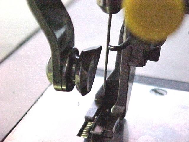
38 1. NEEDLE INSTALLATION D - CORRECT MACHINE APPLICATION Use only the needles number: made in AMF Reece as is adduced in chapter Specifications A. This type of needles was developed in AMF Reece. Double pointed needle which has an eye at the mid point, allows to transmitting the needle from one needle bar to the other and during the sewing maximally imitate the shape of the hand sewing. Except that, this needle does not leave so big holes in sewn material which generally improves the quality of sewing work. To replace the needle follow this steps: 1. Bring the needle to home position by pressing the right foot pedal or by pressing the Up button on the display. 2. To replace the needle, press the emergency Stop button. 3. Fold the needle bar cover. 4. Grasp the needle bar locking nuts and move the needle bar upwards. Hold the needle bar up and remove the original needle. Insert a new needle so that the groove and the eye are from the front view on the left side. Do not install a bent or broken needle. 5. Release the needle bar and close the needle bar cover. 1-26

39 D - CORRECT MACHINE APPLICATION 2. THREADING When threading see the pictures below. Easy threading allows the threading device located on the right side of the needle. 1. Bring the needle to the home position by pressing the right foot pedal or by pressing the Up button on the display. 2. Move the lever of threading device down, so that the hook passes through the needle eye. Place the thread behind a hook and release the thread device lever. 1-27
40 E - STANDARD MACHINE ADJUSTMENT 1. ADJUSTMENT 1-28
41 E - STANDARD MACHINE ADJUSTMENT * SEQUENCE IN 1-29
42 E - STANDARD MACHINE ADJUSTMENT 1-30
43 2. ADJUSTMENT OF NEEDLE BARS 2.1. Adjust the upper needle bar E - STANDARD MACHINE ADJUSTMENT Move the upper needle bar to its DWELL position Use the square head adjustment on the rear of the rocker arm to move the needle bar up and down. First loosen the clamping screw Use the gauge from the accessories to measure 14,2 mm between the lip on the needle bar - not the sleeve to the throat plate Adjust the upper needle bar to the gauge. Tighten the clamping screw Adjust the lower needle bar Bring the needle bar to the closest point while transferring the needle Use the square head adjustment on the rear of the lower rocker arm to move the needle bar up and down. First loosen the clamping screw Use the gauge to measure 23,8 mm between the lip on the lower needle bar and the lip on the upper needle bar. Do not measure to the needle sleeves Adjust the lower needle bar to the gauge. Tighten the clamping screw Move the needle up and down. The needle should be free to move 0,4 to 1,2 mm Adjust the needle release With the needle in the upper needle bar, rotate the handwheel to bring the needle just to the transfer point to the lower needle bar Move the handwheel back and forth slightly to test the needle release from the upper needle bar Loosen the jam nut on the top of the needle bar. Rotate the sleeve adjust nut counterclockwise (viewed from above) quarter turn at a time until the needle does not release. Reverse the nut clockwise until the needle just release at the transfer point. Turn clockwise (half turn). Tighten the jam nut Make the same adjustment on the lower needle bar to get needle release from the lower needle bar to the upper needle bar. Oscillate the handwheel to assure that the needle transfers properly. 1-31
44 E - STANDARD MACHINE ADJUSTMENT 1-32
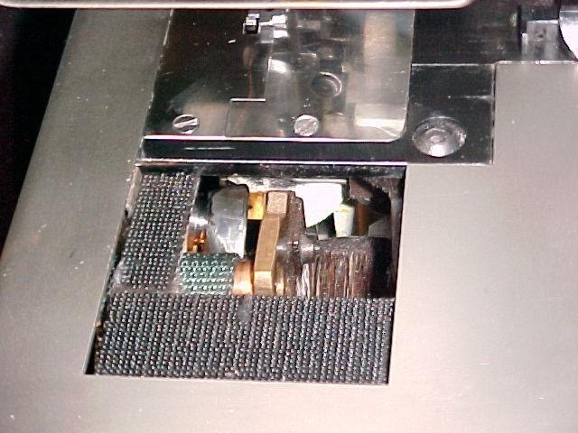
45 E - STANDARD MACHINE ADJUSTMENT 3. ADJUSTMENT AND TIMING OF GRIPPER FINGERS 3.1. Align to the needle Bring the gripper fingers into the closed position Loosen two mounting screws holding the finger bracket Move the finger bracket to get 0,13 mm clearance between the needle and the end of the pads on the gripper fingers. Tighten the screws Adjust finger closing Bring the gripper fingers into the closed position with the lower needle bar in the DWELL position Loosen two screws holding the pivot bracket Move the pivot bracket to close the fingers. Be sure to remove all play in the mechanism. There must be clearance 0,4 mm between the finger lever and the pivot bracket when the fingers are closed only! Tighten the screws Timing the gripper fingers Bring the lower needle bar at 0,8 až 0,4 mm before the needle reaches the DWELL position Loosen the 3 screws clamping the thread clamp cam on the main cam shaft Rotate the cam to just close the gripper fingers. Tighten the clamping screws on the cam. 1-33
46 E - STANDARD MACHINE ADJUSTMENT 1-34
47 E - STANDARD MACHINE ADJUSTMENT 4. ADJUSTING LOOP SUPPORT, THREAD GUIDE, AND SEPARATOR GUIDE 4.1. Adjust the loop support Bring the gripper fingers into the closed position Loosen clamping screw holding the loop support (pyramid) Move the loop support to align its edge with the top fingers on the gripper fingers Bring the lower needle bar all the way up. Make sure that it clears the loop support Adjust the thread guide Bring the lower needle bar to hold the needle in the DWELL position Loosen two screws holding the thread guide Set the thread guide at 0,8 mm from the side of the needle Align the edge of the thread guide with the center of the feed dog. Tighten the screws Adjust the separator guide Loosen the screw holding the separator guide to the drum Set the separator guide so that the thread being carried by the lower looper contacts midway on the upper angle. The thread will then drop properly into the groove. Tighten the screw. Perform the control of the correct setting. Turn the handwheel and check if the looper does not touch the thread separator. 1-35
48 E - STANDARD MACHINE ADJUSTMENT 1-36
49 E - STANDARD MACHINE ADJUSTMENT 5. ADJUSTMENT AND TIMING OF THE THREAD LIFTER 5.1. Adjust lifter hook Move the thread lifter to complete its upward travel Adjust the lifter hook to lift the thread fully into the slot of the separator guide. Do not pinch the thread. Tighten the screw. Check if the lifter hook is not touch by looper after adjustment. The lifter hook can not touch the looper! 6. TIMING THE THREAD BRUSH 6.1. Thread brush opening Bring the lower needle bar to the point where the needle just starts to move from the dwell position Loosen two screws of the brush operating cam on the main cam shaft Rotate the cam to where the thread brush just starts to open. Tighten the cam. 1-37
50 E - STANDARD MACHINE ADJUSTMENT 1-38
51 E - STANDARD MACHINE ADJUSTMENT 7. ADJUSTMENT AND TIMING OF THREAD TENSION FINGER 7.1. Set forward position Remove both throat plates Bring the tension finger to its most forward position (forward operator) Loosen the support block pivot screw. Move the pivot to position the nose of finger at 4,8 to 6,4 mm from the center of the needle. Tighten the screw Timing the tension finger Bring the lower needle bar to the point when the gripper fingers just open Loosen two screws holding the bevel gear on the main cam shaft Rotate the other bevel gear to move the tension finger to its rear position. Tighten the screws on the bevel gear Clearance from the needle Remove both throat plates Rotate the handwheel to move the tension finger through a complete cycle Loosen the screw clamping the eccentric stud. Rotate the eccentric stud to adjust for clearance on the return stroke between the finger and the needle 0,8 mm. Tighten the screw Adjust the stitch tension First set the tension spring by one screw for no tension with the tension finger at the rear position (away from the operator) For tighter stitches adjust for more tension on the tension spring. NOTE: Adjust the support block up or down so that the tension finger moves through the complete cycle without any binding. 1-39
52 E - STANDARD MACHINE ADJUSTMENT 1-40
53 E - STANDARD MACHINE ADJUSTMENT 8. ADJUSTMENT AND TIMING OF MATERIAL FEED 8.1. Position the timing of material feed Bring the eye of the needle flush with the throat plate Loosen the throat plate holder, by two screws, holding the throat plates Position the throat plate for 0,08 to 0,13 mm clearance of the forward end of the slot from needle eye. Make sure that the feed dog and the bender plate are free to operate. Tighten the throat plate holder making sure that it is square with the back casting Adjust feed dog angle Perform this adjustment and the adjustment feed dog height at the same time Bring the feed dog above the throat plate Loosen two screws on the material feed arm to adjust the feed dog Adjust the upper surface of the feed dog parallel with the throat plate. Tighten the screws Adjust feed dog height Bring the feed dog above the throat plate Use the lifter rod to raise or lower the feed dog. Loosen the upper jam nut. Loosen the lower jam nut (left hand thread) Adjust the feed dog for 0,4 to 0,8 mm. Above the throat plate. Tighten the jam nuts Adjust feed dog timing Bring the needle bar at 0,4 to 0,8 mm. before the needle reaches the dwell position Loosen the material feed cam and rotate to just bring the feed dog all the way up. Tighten the feed cam. 1-41
54 E - STANDARD MACHINE ADJUSTMENT 1-42
55 9. TIMING THE FOLLOWER FOOT 9.1. Adjust the follower foot separation E - STANDARD MACHINE ADJUSTMENT This adjustment requires a long arm key or an extension to a standard key. Bend the key as required for access to the gear screw Remove the belt guard. Unhook the cam lever spring for the upper looper Rotate the handwheel to bring the set on the presser foot gear into view. Loosen the set screw Rotate the handwheel to bring the feed dog to the end of stroke where it starts to descend. The follower foot should move upward at this time. Determine whether to advance the follower foot to move upward sooner or retard the follower foot to move later Rotate the handwheel to where the low section of the left upper looper cam uncovers the presser foot gear Hold the right cam looper gear in place. Pull the presser foot gear to disengage from the gearing. Rotate the presser foot gear clockwise to retard the follower foot or counterclockwise to advance. Push the gear in to engage the gearing. Rotate the handwheel to check the timing of the follower foot to the feed dog Repeat steps 5 and 6 until the follower foot separates from the feed dog at the end of its stroke Rotate to bring the set screw on the presser foot gear into view and tighten the screw. Replace the upper looper cam lever spring. Replace the belt guard. Check the right looper timing. 1-43
56 E - STANDARD MACHINE ADJUSTMENT 1-44
57 E - STANDARD MACHINE ADJUSTMENT 10. ADJUSTMENT AND TIMING, LEFT LOOPER AND RIGHT LOOPER Left looper dwell position Loosen two screws to remove the belt guard at the handwheel and of the machine for access to the cam lever Bring the upper needle bar to its maximum upward position Loosen the cam lever screw and locate the tip of the left looper at 4,8 mm from the needle Left looper clearance Rotate the handwheel to bring the left looper alongside the needle Check for 0,2-0,8 mm clearance between the left looper and the needle. If necessary, carefully bend the looper arm to get the proper clearance Left looper height Loosen the left looper arm and adjust the arm to just clear the needle bar on the return stroke. Tighten the arm Run the left looper thought its motion a few times to assure that the arm does strike the needle bar on the return stroke Right looper dwell Bring the upper needle bar to its maximum upward position Loosen the right looper cam lever. Move the right looper for 1,6 až 0,8 mm clearance from the upper needle bar. Tighten the cam lever Looper timing Bring the upper needle bar just to its dwell position Loosen the right looper cam. Rotate the cam to advance the right looper to 0,8 mm ahead of the left looper. Tighten the cam. NOTE: The right looper picks up the thread ahead of the left looper. 1-45
58 E - STANDARD MACHINE ADJUSTMENT 1-46
59 E - STANDARD MACHINE ADJUSTMENT 11. ADJUSTMENT AND TIMING OF LOWER LOOPER Timing the drive gibs Rotate the handwheel by hand to transfer the needle to the upper needle bar. Stop at the point that the retainer ring on the upper needle bar (moving upward) is just flush with the bottom of the needle bar bushing Loosen the arm crank screw. Hold the arm crank assembly and move the lower looper arm out far enough to remove the arm crank Bellow the handwheel remove the nut holding the arm crank drive gear Mark the position of the material feed drive gear Pull the arm crank drive to gear to disengage from the gearing and rotate to make the drive gibs point vertically downward. Reengage the arm crank drive gear to the gearing. Check that the material feed drive gear has not moved Replace the nut on the gear stud and tighten Install the arm crank assembly on the shaft of the lower arm and make sure that the looper arm is seated. Do not tighten. Proceed to the instructions for Timing the lever looper. CAUTION! Whenever the arm crank drive gear is disengaged, all other timings and adjustments must be checked Timing the lower looper Bring the lower needle bar to 0,4 mm before the needle reaches its dwell position. The gripper fingers should just close Loosen the arm crank screw. Hold the drive gibs in place and rotate the bottom looper to position its tip at (12,7 mm Deco 2000 Pick Stitch ) (1 mm Deco 2000 Standard) from the slot in the gripper fingers. Tighten the screw Align the lower hook tip Bring the tip of the lower hook to the gripper fingers Align the tip of the hook at 2 3 mm below the top edge of the gripper fingers (screw at the end of looper arm). Tighten the screw. 1-47
60 E - STANDARD MACHINE ADJUSTMENT 1-48
61 E - STANDARD MACHINE ADJUSTMENT 12. ADJUSTMENT AND TIMING OF BENDER PLATE Raised position of bender plate Loosen two screws to remove the metal table - holder of the throat plates Release the angle plate latch for pick stitch operation. Rotate the handwheel to bring the bender plate fully up Loosen the screw attaching the pusher plate Lift the presser foot away from the bender plate. Move the bender plate for 0,4 mm clearance from the needle. Tighten the screw Adjust bender plate height Bring the bender plate into the down position Loosen the jam nut on the bracket rod. Turn the adjusting bushing to align the end of the bender plate towards the operator flush with the throat plate. This should set the opposite end of the bender plate at 0,4 mm above the throat plate. Tighten the jam nut Align to the throat plate Loosen the clamping screw and also loosen two screws holding the pivot support Align the edge of the notch for the feed dog on the bender plate with the edge of the feed dog slot on the throat plate Tighten the pivot support screws. Adjust the pins to the bender plate and tighten the clamping screw Timing the plate Release the angle plate latch for pick stitch operation Rotate the handwheel to move the needle into the lower needle bar Rotate to bring the presser foot down to the throat plate. Stop when the presser foot is 0,4 mm above the throat plate Loosen two screws holding the angle plate cam on the main cam shaft Rotate the cam to just start the bender upward. Tighten the cam. 1-49
62 E - STANDARD MACHINE ADJUSTMENT 1-50
63 E - STANDARD MACHINE ADJUSTMENT Adjust the angle plate latch Rotate the handwheel to bring the roller onto the high section of the angle plate cam on the main cam shaft Loosen the mounting of the angle plate latch two screws on the tie bracket Adjust the latch to snap onto locking clip. Tighten the mounting Adjust cam lever spring Loosen the jam nut on the stud attaching the cam lever spring to tie bracket Use the other nut to adjust the pressure of the roller on the cam lever against the angle plate cam Operate the machine. The roller should stay in positive contact with the cam. Tighten the jam nut Presser foot tension Run the upper nut on the top of the presser foot rod to two threads from the top Turn the underneath nut to move the spring clip against the upper nut. Tighten the two nuts Rod spring compression Bring the bender plate to the fully up position Lift the presser foot and then reset on the bender plate. The presser foot should move down to contact the throat plate Loosen the collar under the rod spring on the angle stitch mechanism Rotate the collar to increase or decrease the compression of the rod spring. Find the point that the bender plate just lifts the presser foot away from the throat plate. Then back off two turns on the collar to decrease the compression on the rod spring. Tighten the collar Operate the machine to check the stitching on the material being used. If the stitch length varies increase the compression on the rod spring. 1-51
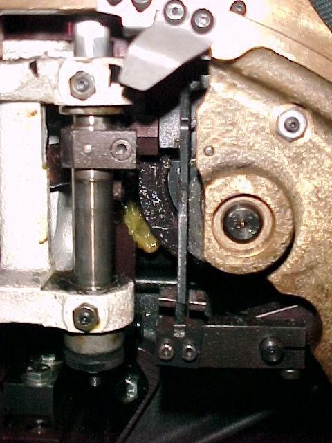
64 13. STEP MOTOR SET UP E - STANDARD MACHINE ADJUSTMENT Set up the gap 0,25 mm between the sensor face and flag on the cam. 1-52
65 E - STANDARD MACHINE ADJUSTMENT 14. SETTING - UP PROCEDURE FOR FEED DOG SENSOR AND FLAG Ensure 0,8 mm gap between feed dog sensor and assembly. Sensor cable harness connector must be fitted into SK 3 on main card. Check correct mains voltage setting is selected. Switch on machine. Pull the handwheel round by hand keeping an eye on feed dog as feed dog goes below throat plate - stop. Adjust flag assembly next to feed dog sensor so small red L.E.D. just comes on. Tighten flag and sensor maintaining 8 mm gap. 1-53
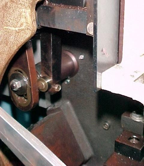
66 15. BELT TENSION ADJUSTMENTS E - STANDARD MACHINE ADJUSTMENT The V belt can be released after some time of using the machine, which may worsen the productivity. That is why its necessary to check the belt tension. 1. To tighten the V belt fold the machine working table and loosen two nuts and two screws Move the bracket down as needed and tighten two nuts. 3. After the V belt is adjusted it is necessary to adjust the T belt: Loosen the nuts, move the motor downas needed and then tighten the screws. 4. Check the tension by the pressure approximately 10 N above the plate. The sag of the belt should be approximately 10 mm. 5. To tighten the belt on the step motor loosen the screw on the step motor holder and move the holder with step motor in direction away from the machine. Tighten the screw. 1-54
67 1. PRINCIPLES OF MACHINE MAINTENANCE F - MACHINE MAINTENANCE WARNING: - To make any maintenance turn off the main switch. - Do not modify the machine in any way, which could damage electronic devices and machine mechanisms. CAUTION: - Always keep the safety rules valid in the organization. WARNING: - Check if the electrical cables are not damaged. - Check safety covers for damage and replace if needed immediately. - Keep your hands out of the sewing area! - Do not modify the machine in any way which could eliminate safety parts. CAUTION: - Do not neglect periodic maintenance. - If there is problem with electrical power supply, switch off the operating switch (circuit breaker) - Do not damage, correct and remove safety labels. - Do not work with the machine when you are under the influence of drugs or alcohol. - User has to ensure the lighting of the working area minimal 750 Luxes. 1-55
68 2. MACHINE CLEANING AND MAINTENANCE 1. Switch off the electrical power supply. F - MACHINE MAINTENANCE 2. Use the brushes from the accessories to clean the thread lints and fabric from the sewing mechanism. Turn the handwheel to rotate with the sewing mechanism. Clean the thread waste from the roller daily. Lift the working table and perform the cleaning by the air-blowing. Do not forget to clean the waste on the control box air gird. WARNING! When covering the working table take care of hands. Possible injury! 3. Lubricate the machine daily 4. Perform visual check of mechanism especially in area of sewing mechanism. 5. When the maintenance and checking is finished, close covers. 3. MACHINE LUBRICATION 1. It is necessary to lubricate daily all places said below, lubricate soundly especially when the machine is switched on for the first time or after a long idle period. Use the oil ESSO TERESSO 68 or oil with similar quality. 2. Too much oil may cause its overflowing around the needle bar area. 3. To lubricate the needle bar fold the needle bar cover. Few drops of oil drop on the needle bar above bearing, to the needle bar center, and do not forget to lubricate the lower needle bar and conducting sleeve area. Close the cover. 1-56

69 F - MACHINE MAINTENANCE 1-57
MODEL CBS 13 BUTTON SEWING AND NECK WRAPPING PARTS AND SERVICE MANUAL PART NUMBER MACHINE SERIAL No:
 MODEL CBS 13 BUTTON SEWING AND NECK WRAPPING PARTS AND SERVICE MANUAL MACHINE SERIAL No: PART NUMBER 97.7300.0.000 This manual is valid from the machine Serial No.: T CBS0002 10 / 2017 MODEL MODEL CBS
MODEL S-211 ELECTRONIC EYELET BUTTONHOLE MACHINE PARTS AND SERVICE MANUAL PART NUMBER MACHINE SERIAL No.
 MODEL ELECTRONIC EYELET BUTTONHOLE MACHINE PARTS AND SERVICE MANUAL MACHINE SERIAL No. PART NUMBER 97. 1990.0.001 This manual is valid from the machine serial No.: G190137 AMF is trademark of AMF Group,
ENGINEER S MANUAL No.01
 1-NEEDLE, UNISON FEED, LOCKSTITCH MACHINE (AUTOMATIC LUBRICATION) LU-1510 1-NEEDLE, UNISON FEED, LOCKSTITCH MACHINE WITH AUTOMATIC THREAD TRIMMER (AUTOMATIC LUBRICATION) LU-1510-7 1-NEEDLE, UNISON FEED,
IMPORTANT SAFETY INSTRUCTIONS
 CONTENTS 1.SPECIFICATIONS... 1 2.INSTALLATION... 1 3.INSTALLATION OF THE SYNCHRONIZER... 2 4.ASSEMBLY OF HAND WHEEL... 2 5.INSTALLATION OF HAND WHEEL... 2 6.INSTALLING THE BELT COVER... 3 7.ADJUSTING THE
Omron MODEL S-4000 TKF, LS TACKER AND LABEL SEWER PARTS AND SERVICE MANUAL
 MODEL S-4000 TKF, LS Omron TACKER AND LABEL SEWER PARTS AND SERVICE MANUAL MACHINE SERIAL No.: PART NUMBER 97.2441.1.001 This manual is valid from the machine serial number M241428 AMF is trademark of
MODEL S-4000 ISBH Omron
 MODEL S-4000 ISBH Omron STRAIGHT BUTTONHOLE MACHINE FOR IMITATION SLEEVE BUTTONHOLES PARTS AND SERVICE MANUAL MACHINE SERIAL No.: PART NUMBER 97.2433.1.001 This manual is valid from the machine serial
MODEL S-4000 ISBH+I SM
 MODEL S-4000 ISBH+I SM ELECTRONIC BUTTONHOLE MACHINE PARTS AND SERVICE MANUAL MACHINE SERIAL No: PART NUMBER 97.2486.3.001 This manual is valid from the machine Serial No.: R241683 09 / 2015 LIMITED WARRANTY
MSK-8900M Industrial Sewing Machine. Instruction Manual
 MSK-8900M Industrial Sewing Machine Instruction Manual CONTENTS Operation instruction. Brief introduction. Main specifications. Main parts name 4. The method of installation 5 5. Pareparation before sewing
Please read this manual before using the machine. Please keep this manual within easy reach for quick reference.
 INSTRUCTION MANUAL Please read this manual before using the machine. Please keep this manual within easy reach for quick reference. HIGH SPEED SINGLE NEEDLE STRAIGHT LOCK STITCHER Thank you very much for
DA-9270 TWIN NEEDLE (THREE NEEDLE) FEED OFF THE ARM DOUBLE CHAIN STITCHER. English
 FEED OFF THE ARM DOUBLE CHAIN STITCHER. English") TWIN NEEDLE (THREE NEEDLE) FEED OFF THE ARM DOUBLE CHAIN STITCHER English Thank you very much for buying a BROTHER sewing machine. Before using your new machine, please read the safety instructions below
TWIN NEEDLE (THREE NEEDLE) FEED OFF THE ARM DOUBLE CHAIN STITCHER English Thank you very much for buying a BROTHER sewing machine. Before using your new machine, please read the safety instructions below
PLC-1700 Series PLC-1710, , 1760, , 1760L
 Post-bed, Unison-feed, Lockstitch Machine PLC-1700 Series PLC-1710, 1710-7, 1760, 1760-7, 1760L ENGINEER S MANUAL 40040656 No.E372-00 Introduction This Engineer s Manual is for technical service engineers.
Please read this manual before using the machine. Please keep this manual within easy reach for quick reference.
 DA-927A DA-928A INSTRUCTION MANUAL Please read this manual before using the machine. Please keep this manual within easy reach for quick reference. TWIN NEEDLE / THREE NEEDLE FEED OFF THE ARM DOUBLE CHAIN
MODEL XL-21 EYELET BUTTONHOLE MACHINE PARTS AND SERVICE MANUAL PART NUMBER MACHINE SERIAL No.
 MODEL XL-21 EYELET BUTTONHOLE MACHINE PARTS AND SERVICE MANUAL MACHINE SERIAL No. AMF is trademark of AMF Group, Inc. PART NUMBER 97. 1800.2.002 This manual is valid from the machine serial No.: F180291
Please read this manual before using the machine. Please keep this manual within easy reach for quick reference.
 INSTRUCTION MANUAL Please read this manual before using the machine. Please keep this manual within easy reach for quick reference. SINGLE NEEDLE DIRECT DRIVE STRAIGHT LOCK STITCHER WITH THREAD TRIMMER
BL Series INSTRUCTIONS
 BL Series Models: EX5204/BL514 EX5204/BL515 EX5214/BL524 EX5214/BL525 EXT5214/BL524 EXT5214/BL525 EX5404/BL614 EX5404/BL615 EX5414/BL624 EX5414/BL625 EXT5214H/BL528 EXT5214H/BL529 Automatic Backlatcher
USER S MANUAL. SS-7350 Series. Small cylinder bed interlock sewing machine
 R USERS MANUAL SS-7350 Series Small cylinder bed interlock sewing machine R Best Quality Best Price Best Service 1. Thank you for purchasing our product. Based on the rich expertise and experience accumulated
CONTENTS 1. SPECIFICATIONS SET-UP FOR THE OPERATOR MAINTENANCE... 34
 ENGLISH ii CONTENTS. SPECIFICATIONS... 2. SET-UP.... Installing the motor unit... 2. Installing the control box... 3. Installing the belt... 2 4. Adjusting the pulley cover... 2 5. Installation and adjustment
Technical Data. Name: ERIKA Automat fully automatic machine to divide and to round dough pieces of the same size
 AUTOMAT MANUAL 1 Technical Data Name: ERIKA Automat fully automatic machine to divide and to round dough pieces of the same size Type Divisions Dough Portions (in ounces) Plate Nos. 3 30 1.0 3.5 #35 4/40A
Part 2: Installation Instructions cl
 Contents Page: Part 2: Installation Instructions cl. 381-382 1. Delivery scope............................... 3 2. General and Transportation safety precautions........... 3 3. Stand installation 3.1 Installing
Industrial Sewing Machine TECHNICAL MANUAL SEWING MACHINE HEAD. Electronic Pattern Sewing Machine. Model PLK-G1010 A180E593P03
 Industrial Sewing Machine TECHNICAL MANUAL SEWING MACHINE HEAD Electronic Pattern Sewing Machine Model PLK-G1010 A180E593P03 FOR SAFE USE Before the installation, operation, and inspection for this product,
RH-981A ENGLISH ELECTRONIC EYELET BUTTON HOLER
 ENGLISH ELECTRONIC EYELET BUTTON HOLER Thank you very much for buying a BROTHER sewing machine. Before using your new machine, please read the safety instructions below and the explanations given in the
MODEL S-311+I OPERATING INSTRUCTIONS S-311+I
 MODEL S-311+I OPERATING INSTRUCTIONS TABLE OF CONTENTS A - INTRODUCTION... 1. GENERAL INFORMATION... 2. SAFETY LABELS AND EQUIPMENT DEVICE... 3. SPECIFICATIONS... B - MACHINE ASSEMBLY... S-311+I AF -
BARRACUDA 200ZW PORTABLE WALKING FOOT SEWING MACHINE INSTRUCTION MANUAL
 BARRACUDA 00ZW PORTABLE WALKING FOOT SEWING MACHINE INSTRUCTION MANUAL THE BARRACUDA 00ZW PORTABLE WALKING FOOT SEWING MACHINE INSTRUCTION MANUAL MATERIAL IS OWNED BY RELIABLE AND MAY NOT BE REPRODUCED
Industrial Sewing Machine TECHNICAL MANUAL SEWING MACHINE HEAD. Electronic Pattern Sewing Machine. Model PLK-G2516 A180E621P01
 Industrial Sewing Machine TECHNICAL MANUAL SEWING MACHINE HEAD Electronic Pattern Sewing Machine Model PLK-G2516 A180E621P01 FOR SAFE USE Before the installation, operation, and inspection for this product,
OPERATING MANUAL Gfp 255C Please read this manual carefully before operating!
 OPERATING MANUAL Gfp 255C Please read this manual carefully before operating! Unpacking, assembly, and operating videos are available at www.gfpsmoothstart.com 1 Table of Contents Gfp 255C March 2015 Contents
PREMIER SERIES BY P1255RBL-18 P2339RBL-18
 PREMIER SERIES BY P1255RBL-18 P2339RBL-18 P2339RBL-18 P1255RBL-18 P2339RBL- P1255RB- P2339RBL- 1. P2339RBL 18 Machine casting components Line Part Number Description Qt. Notes 1 300 1002 Machine
Industrial Sewing Machine TECHICAL MANUAL SEWING MACHINE HEAD. Electronic Pattern Sewing Machine. Model PLK-G1010 A180E593P02
 Industrial Sewing Machine TECHICAL MANUAL SEWING MACHINE HEAD Electronic Pattern Sewing Machine Model PLK-G1010 A180E593P02 FOR SAFE USE Before the installation, operation, and inspection for this product,
WHEATGRASS JUICER C O M M E R C I A L. INSTRUCTION MANUAL Model No
 COMMERCIAL PRODUCTS ATTENTION If any components of this unit are broken, do not operate properly, or for product returns, please contact Pragotrade at 1-800-814-4895 Outside the U.S. call 440-638-3131.
Part 3: Service manual, class
 Contents Page: Part : Service manual, class 7-75. General.................................................. Gauges................................................. 4. Description and adjustment of the
TACH-IT MODEL #3568 SEMI-AUTOMATIC TWIST TIE MACHINE OPERATION MANUAL AND PARTS LIST
 TACH-IT MODEL #3568 SEMI-AUTOMATIC TWIST TIE MACHINE OPERATION MANUAL AND PARTS LIST 1 TABLE OF CONTENTS: SECTION 1 CAUTION PAGE 3 SECTION 2 PARTS IDENTIFICATION PAGE 4 SECTION 3 MACHINE DIMENSIONS AND
52 SAN LUCAS CEILING FAN
 52 SAN LUCAS CEILING FAN Owner s Manual Models #20551 If a problem cannot be remedied or you are experiencing difficulty in installation, please contact the Service Department: 1-877-459-3267, 9 a.m.-
52 BARSTOW CEILING FAN
 52 BARSTOW CEILING FAN Owner s Manual Models #20519 If a problem cannot be remedied or you are experiencing difficulty with installation, please contact the Service Department: 1-877-459-3267, 9 a.m.-
Model PLK-G5050 PLK-G10050
 Industrial Sewing Machine TECHNICAL MANUAL SEWING MACHINE HEAD Electronic Pattern Sewing Machine Model PLK-G5050 PLK-G10050 A180E686P01 FOR SAFE USE Before the installation, operation, and inspection for
ASG EZ-9000GR Tape Dispenser User Manual ASG #66136
 ASG EZ-9000GR Tape Dispenser ASG #66136 Revision Date: 03/27/18 1 Read Before Use Warnings and Cautions The safety guidelines in this instruction manual must be observed in order to prevent injury to the
PARTS LIST. CoverPro 900CP & 1000CP
 PARTS LIST CoverPro 900CP & 00CP 1 5 2 7 9 3 6 11 20 23 12 13 1 19 21 2 26 17 16 1 22 15 25 1 No. Part number Description 1 79560300 Face cover unit 2 79501600 Face cover 3 0602006 Thread cutter unit 000115700
52 STRATHMERE CEILING FAN
 52 STRATHMERE CEILING FAN Owner s Manual Models #20341 If a problem cannot be remedied or you are experiencing difficulty with installation, please contact the Service Department: 1-877-459-3267, 9 a.m.-
Cable Drum Machine. Operation Manual 40 SERIES. Cleans 2" to 4" lines up to 75' N O T F O R R O O T S
 Cable Drum Machine Operation Manual 40 SERIES Cleans 2" to 4" lines up to 75' Used For: Sinks, Showers & Floor Drains N O T F O R R O O T S WARNING - Read All Instructions, When Using Electric Tools, Basic
DDL-900B INSTRUCTION MANUAL
 DDL-900B INSTRUCTION MANUAL CONTENTS I. SPECIFICATIONS... 1 II. SET-UP... 3 1. Installation...3 2. Installing the pedal sensor...4 3. Installing the power switch (for CE)...4 4. Connecting the connector...5
DDL-8700B-7 INSTRUCTION MANUAL
 DDL-8700B-7 INSTRUCTION MANUAL I CONTENTS I. SPECIFICATIONS... 1 II. SET-UP... 3 1. Installation...3 2. Installing the pedal sensor...4 3. Connecting the connector...4 4. How to install the power plug...5
Torrena 42 Ceiling Fan
 Torrena 42 Ceiling Fan Owner s Manual Part # 269268, 269269 Model # 32096, 32097 Exclusively Distributed by: HD Supply Facilities Maintenance, Ltd. Atlanta, GA 30339 2017 Made in China If you are experiencing
52 BERKSHIRE CEILING FAN
 52 BERKSHIRE CEILING FAN Owner s Manual Models #20223, 20224 If a problem cannot be remedied or you are experiencing difficulty in installation, please contact the Service Department: 1-877-459-3267, 9
(3 plastic wire connectors,blade balancing kit, 2 extra mounting screws #10-32 for outlet box.)
") Excel Lighting & Manufacturing Ltd. Lifetime Limited Warranty Excel Lighting & Manufacturing Ltd. Warrants the fan motor to be free from defects in workmanship and material present at time of shipment
Excel Lighting & Manufacturing Ltd. Lifetime Limited Warranty Excel Lighting & Manufacturing Ltd. Warrants the fan motor to be free from defects in workmanship and material present at time of shipment
Camarillo 52 Ceiling Fan
 Owner s Manual Camarillo 52 Ceiling Fan Part # 269263, 269259, 269287 Model # 32091, 32092, 32087 Exclusively Distributed by: HD Supply Facilities Maintenance, Ltd. Atlanta, GA 30339 2017 Made in China
DDL-900A INSTRUCTION MANUAL
 DDL-900A INSTRUCTION MANUAL COVERI CONTENTS I. SPECIFICATIONS... 1 II. SET-UP... 3 1. Installation...3 2. Installing the pedal sensor...4 3. Installing the power switch (for CE)...4 4. Connecting the connector...5
SC-922 InStruCtIon Manual
 SC-922 Instruction Manual CONTENTS I. SPECIFICATIONS... 1 II. SET-UP... 1 1. Installing to the table...1 2. Installing the motor unit...2 3. Installing the control box...2 4. Installing the belt...3 5.
45 Wide Format Hot and Cold Laminator
 45 Wide Format Hot and Cold Laminator 1 IMPORTANT SAFEGUARDS OPERATING INSTRUCTIONS TCC1200 When using electrical machines, basic precautions should always be followed to reduce the risk of electric shock
MB-1800 Series INSTRUCTION MANUAL
 MB-800 Series INSTRUCTION MANUAL CONTENTS!. SPECIFICATIONS... @. NAME OF EACH COMPONENT.... Name of the main unit... #. INSTALLATION... $. PREPARATION OF THE SEWING MACHINE...7. Attaching the needle...
Instruction Manual. Dogeroo, Super Dogeroo, and Mini Dogeroo
 Instruction Manual Dogeroo, Super Dogeroo, and Mini Dogeroo Model No. 8102, 8103, 8108 10700 Medallion Drive, Cincinnati, Ohio 45241-4807 USA Part No. 87793 SAFETY PRECAUTIONS Page 2 INSTALLATION INSTRUCTIONS
TECHNICAL INFORMATION Touchtronic Clothes Dryers
 TECHNICAL INFORMATION Touchtronic Clothes Dryers Includes: T1302, T1303, T1322, T1329ci T1403 & T1405 2004 Miele This page intentionally left blank. Table of Contents GENERAL INFORMATION A. Warning and
52 CEILING FAN. Owner s Manual Models #50336, 50337
 52 CEILING FAN Owner s Manual Models #50336, 50337 If a problem cannot be remedied or you are experiencing difficulty in installation, please contact the Service Department: 1-877-706-3267, 9 a.m.- 5 p.m.
Please read this manual before using the machine. Please keep this manual within easy reach for quick reference.
 INSTRUCTION MANUAL Please read this manual before using the machine. Please keep this manual within easy reach for quick reference. SINGLE NEEDLE DIRECT DRIVE LOCK STITCHER WITH ELECTRONIC FEEDING SYSTEM
AK-154 INSTRUCTION MANUAL
 AK-154 INSTRUCTION MANUAL 1 CONTENTS 1. FEATURES... 1 2. INSTALLATION... 2 3. HOW TO SELECT THE FUNCTION OF AUTO-LIFTER... 5 4. OTHERS (Advanced edition)... 6 4-1. Function for reducing the presser foot
/11, -14/31 INSTRUCTION MANUAL. This instruction manual applies to machines from the following serial numbers onwards: #
 3834-4/, -4/3 INSTRUCTION MANUAL This instruction manual applies to machines from the following serial numbers onwards: # 2 733 53 296-2-8 936/002 Betriebsanleitung engl. 06.09 This Instruction manual
WAILEA OWNER S MANUAL
 WAILEA OWNER S MANUAL The blades in each pack are matched for equal weight to assure smooth fan operation. If more than one fan is being installed, be careful not to mix blades from different cartons.
Thank you for purchasing Pegasus automatic unit.
 HG Series odels: HG-110/W664-08 HG-130/WT664-08 HG-140/WT664-35 Thank you for purchasing Pegasus automatic unit. Study this manual very carefully before beginning any of the procedure and then use the
Fly / Rear Deltoid. Owners Manual
 Owners Manual . Assembly Instructions Item Qty Description Part Number Item Qty Description Part Number Front Upright AAP04-0746 (WHT)(PLT) 7 Weight Stack Pin P-0048 Tower AP04-0745 (WHT)(PLT) 8 Center
TECHNICAL INFORMATION B 890 and B 990 Rotary Irons (US Models)
") TECHNICAL INFORMATION B 890 and B 990 Rotary Irons (US Models) 2011 Miele USA Table of Contents A B C D 010 Warning and Safety Instructions... 5 1 General... 5 2 Touch Current Measurement... 6 3 Risk of
TECHNICAL INFORMATION B 890 and B 990 Rotary Irons (US Models) 2011 Miele USA Table of Contents A B C D 010 Warning and Safety Instructions... 5 1 General... 5 2 Touch Current Measurement... 6 3 Risk of
52 BAYTOWNE CEILING FAN
 52 BAYTOWNE CEILING FAN Owner s Manual Models #20501 If a problem cannot be remedied or you are experiencing difficulty in installation, please contact the Service Department: 1-877-459-3267, 9 a.m.- 5
Gfp 400 Series August Gfp 463 TH. Please read this manual carefully before operating!
 OPERATING MANUAL Gfp 455 TH Gfp 463 TH Please read this manual carefully before operating! 1 Table of Contents Gfp 400 Series August 2015 Contents Page 1. Introduction 3 2. Important Safety Instructions..
30-YEAR LIMITED WARRANTY
 PROGRESS LIGHTING 30-YEAR LIMITED WARRANTY PROGRESS LIGHTING FAN MOTORS ARE WARRANTED TO THE END USER TO BE FREE OF ELECTRICAL AND/OR MECHANICAL DEFECTS FOR A PERIOD OF 30 (THIRTY) YEARS FROM DATE OF SALE.
DDL-900BB INSTRUCTION MANUAL
 DDL-900BB INSTRUCTION MANUAL CONTENTS I. SPECIFICATIONS... 1 II. SET-UP... 3 1. Installation...3 2. Installing the pedal sensor...4 3. Installing the power switch (for CE)...5 4. Connecting the connector...6
DDL-9000A Series. Direct-drive, High-speed, Lockstitch Machine with Automatic Thread Trimmer. High-end model of JUKI 1-needle lockstitch machines
 DDL-9000A Series Direct-drive, High-speed, Lockstitch Machine with Automatic Thread Trimmer DDL-9000A Series High-end model of JUKI 1-needle lockstitch machines A genuine sewing machine which makes the
Cleaning unit for coolant. :_decftez`_>r_fr] Book No.: V2
![Cleaning unit for coolant. :_decftez`_>r_fr] Book No.: V2](/thumbs/90/104143238.jpg "Cleaning unit for coolant. :_decftez`_>r_fr] Book No.: V2") Cleaning unit for coolant :_decftez`_>r_fr] Book No.: 1271526-02 V2 Alfa Laval Separation AB Separator Manuals, dept. SKEL S-147 80 Tumba, Sweden Telephone: +46 8 53 06 50 00 Telefax: +46 8 53 03 10 40
Cleaning unit for coolant :_decftez`_>r_fr] Book No.: 1271526-02 V2 Alfa Laval Separation AB Separator Manuals, dept. SKEL S-147 80 Tumba, Sweden Telephone: +46 8 53 06 50 00 Telefax: +46 8 53 03 10 40
FM740 INSTRUCTION MANUAL VACUUM CLEANER. Contents HOUSEHOLD USE ONLY
 INSTRUCTION MANUAL VACUUM CLEANER FM70 Contents IMPORTANT SAFETY INSTRUCTIONS NAMES OF EACH PART PREPARATIONS BEFORE USE USING THE VACUUM CLEANER USING THE ATTACHMENTS EMPTYING THE DUST COMPARTMENT CLEANING
CEILING FAN OWNER'S MANUAL
 Style that revolves around you. CEILING FAN OWNER'S MANUAL QUATRO 10/09 WARNING: Read and follow these instructions carefully and be mindful of all warnings shown throughout. GENERAL INSTALLATION & OPERATION
SEWING MACHINE 45 / 21 STITCH
 SEWING MACHINE 45 / 21 STITCH 90715 ASSEMBLY AND OPERATING INSTRUCTIONS 3491 MISSION OAKS BLVD., CAMARILLO, CA 93011 VISIT OUR WEB SITE AT HTTP://WWW.HARBORFREIGHT.COM Copyright 2003 by Harbor Freight
Operator s Manual S-333. Automated Soil Compactor. Version 3.3. Durham Geo Slope Indicator 2175 West Park Court Stone Mountain, GA USA
 Automated Soil Compactor S-333 Operator s Manual Version 3.3 Durham Geo Slope Indicator 2175 West Park Court Stone Mountain, GA 30087 USA Phone: 800-837-0864 or +1.770.465.7557 Fax: 770.465.7447 e-mail:
MIXERS SMX10-1, SMX20-1, SMX20-2, SMX30-1 INSTRUCTION MANUAL
 SMX10-1, SMX20-1, SMX20-2, SMX30-1 MIXERS This manual contains important information regarding your Supera unit. Please read this manual thoroughly prior to equipment set-up, operation and maintenance.
Instruction Manual and Parts List. Ultra High Speed Overedge and Safety Stitch Machine
 Instruction Manual and Parts List Ultra High Speed Overedge and Safety Stitch Machine 32D 3M-04 3M-04 / KS 32M-05 34M-04 24M-24 24M-24 / KS 244M-24 25M-35 25M-35 / KH 25M-55 25M-55 / KH 25M-56 25H-56 /
Altra Series Dampener
 Crestline TM Altra Series Dampener Installation Instructions Heidelberg MO X88-66 10/97 Rev-A GENERAL INFORMATION ATTENTION CRESTLINE ALTRA SERIES TM DAMPENER OWNER! Accel Graphic Systems provides parts
Please read this manual before using the machine. Please keep this manual within easy reach for quick reference.
 INSTRUCTION MANUAL Please read this manual before using the machine. Please keep this manual within easy reach for quick reference. SINGLE NEEDLE DIRECT DRIVE LOCK STITCHER WITH ELECTRONIC FEEDING SYSTEM
LIMITED LIFETIME WARRANTY
 LIMITED LIFETIME WARRANTY Model No.: FN52317 aireryder ORIGINAL CEILING FAN LIMITED LIFETIME WARRANTY The limited lifetime warranty covers this ceiling fan, for residential use by the original purchaser,
Shredder FD 8906CC Cross-Cut
 Shredder FD 8906CC Cross-Cut 1/2017 OPERATOR MANUAL Machine Specs Model: FD 8906CC Motor Power Sheet Capacity Serial #: 7.5KW (10HP) Three-phase, 220V, 50/60 Hz, 50 Amp dedicated line required, CS8365
1715HD, 2015HD Instructions For Use Models: ,
 1715HD, 2015HD Instructions For Use Models: 56380201, 56380202 12/09 Form Number 56041825 IMPORTANT SAFETY INSTRUCTIONS This machine is only suitable for commercial use, for example in hotels, schools,
48 TAYLOR CEILING FAN
 48 TAYLOR CEILING FAN Owner s Manual Models #20554 If a problem cannot be remedied or you are experiencing difficulty in installation, please contact the Service Department: 1-877-459-3267, 9 a.m.- 5 p.m.
PLC-2700 Series INSTRUCTION MANUAL
 PLC-2700 Series INSTRUCTION MNUL CONTENTS 1. SPECIFICTIONS... 1 2. INSTLLTION... 4 2-1. Installation of the sewing machine...4 2-2. djusting the belt tension (PLC-2710, 2760, 2760L, 2765)...6 2-3. Pneumatic
LK-1903B/BR35 INSTRUCTION MANUAL
 LK-1903B/BR35 INSTRUCTION MANUAL CONTENTS I. SPECIFICATIONS...1 1. Specifications... 1 2. Model classification according to the button size... 2 3. Shape of buttons... 2 II. NAME OF EACH COMPONENT...3
PS-2/ES Automated pack & tag machine with IndES fastening system
 English Manual PS-2/ES Automated pack & tag machine with IndES fastening system Contents 1. Introduction 2. Important Safety Instructions 3. PS-2/ES 4. Unpacking the machine 5. Setting up the machine 6
Products documentation (REVISION DATE: 03/10/2011) OMFP6010 (60cm PIROLITIC OVEN)
 OMFP6010 (60cm PIROLITIC OVEN)") Products documentation (REVISION DATE: 03/10/2011) OMFP6010 (60cm PIROLITIC OVEN) Ovens Service Manual Models OMFP6010 CONTENTS This document has been published to be used for service only. The contents
Products documentation (REVISION DATE: 03/10/2011) OMFP6010 (60cm PIROLITIC OVEN) Ovens Service Manual Models OMFP6010 CONTENTS This document has been published to be used for service only. The contents
Operating Manual Model BP500 and BP500 IJ Tape Dispenser
 Operating Manual Model BP500 and BP500 IJ Tape Dispenser Meets UL and CE Electrical and Safety Standards BETTER PACKAGES 4 Hershey Drive, Ansonia, CT 06401 Website: www.betterpackages.com BP P/N: MAN-500-OPR
PARTS LIST. Specification code: (JAI 45231) (JA) (JCA) (JUK) (JHBV)
 (JA) (JCA) (JUK) (JHBV)") PARTS LIST Specification code: 832-711-004 (JAI 45231) 832-712-005 (JA) 832-713-006 (JCA) 832-714-007 (JUK) 832-716-009 (JHBV) 14 13 1 2 6 10 12 9 11 8 7 3 5 4 7 1 KEY PART NO. NO. NAME 1 832649011 Needle
PARTS LIST Specification code: 832-711-004 (JAI 45231) 832-712-005 (JA) 832-713-006 (JCA) 832-714-007 (JUK) 832-716-009 (JHBV) 14 13 1 2 6 10 12 9 11 8 7 3 5 4 7 1 KEY PART NO. NO. NAME 1 832649011 Needle
SPACESAVER INSTRUCTION MANUAL WARRANTY CERTIFICATE
 SPACESAVER BY INSTRUCTION MANUAL WARRANTY CERTIFICATE Manual design and all elements of manual design are protected by U.S. Federal and/or State Law, including Patent, Trademark and/or Copyright laws.
USER S MANUAL. KM-1060BL Series KM-1060BL KM-1060BL-7 KM-1062BL KM-1062BL-7
 USER S MANUAL KM-1060BL Series KM-1060BL KM-1060BL-7 KM-1062BL KM-1062BL-7 R Best Quality Best Price Best Service 1. Thank you for purchasing our product. Based on the rich expertise and experience accumulated
I N ST R UC T I ON. MODEL HAB500 AroMatic TM BREAD SLICERS MODEL FORM (4-99) AROMATIC BREAD SLICER 701 S. RIDGE AVENUE TROY, OHIO
 AROMATIC BREAD SLICER 701 S. RIDGE AVENUE TROY, OHIO") I N ST R UC AROMATIC BREAD SLICER T I ON S MODEL HAB500 AroMatic TM BREAD SLICERS MODEL HAB500 ML-104845 701 S. RIDGE AVENUE TROY, OHIO 45374-0001 FORM 34198 (4-99) TABLE OF CONTENTS GENERAL..........................................................
I N ST R UC AROMATIC BREAD SLICER T I ON S MODEL HAB500 AroMatic TM BREAD SLICERS MODEL HAB500 ML-104845 701 S. RIDGE AVENUE TROY, OHIO 45374-0001 FORM 34198 (4-99) TABLE OF CONTENTS GENERAL..........................................................
Safety, Operation and Maintenance Manual with Parts List
 Safety, Operation and Maintenance Manual with Parts List Important Information and Safety Instructions PLEASE READ BEFORE USE! 961130022-10/10-Rev1 TABLE OF CONTENTS Safety Instructions...2 Grounding Instructions...4
INTELLI-VAC 14 INTELLI-VAC 18
 INTELLI-VAC 14 INTELLI-VAC 18 INTRODUCTION OPERATING & MAINTENANCE INSTRUCTIONS This operator s book has important information for the use and safe operation of this machine. Read this book carefully before
Owner's Manual Paramount 65X GRAPHIC LAMINATION PRODUCTS
 Owner's Manual Paramount 65X GRAPHIC LAMINATION PRODUCTS Royal Sovereign International Inc. Please read and retain these instructions. To register your product, please go to www.royalsovereign.com www.royalsovereign.com
MODEL EBS Mark II ELETRONIC BUTTON STITCHER MACHINE PARTS AND SERVICE MANUAL PART NUMBER MACHINE SERIAL No:
 MODEL EBS Mark II ELETRONIC BUTTON STITCHER MACHINE PARTS AND SERVICE MANUAL MACHINE SERIAL No: PART NUMBER 97.7100.0.000 This manual is valid from the machine Serial No.: L710004 AMF je obchodní značka
Turin LED Ceiling Fan
 Turin LED Ceiling Fan model no. no. 052-6972-6 Instruction Manual Toll-free: -866-827-4985 IMPORTANT: Please read and understand this manual before any assembly. Before beginning assembly of product, make
ALUMA INSTRUCTION MANUAL WARRANTY CERTIFICATE
 ALUMA BY INSTRUCTION MANUAL WARRANTY CERTIFICATE Manual design and all elements of manual design are protected by U.S. Federal and/or State Law, including Patent, Trademark and/or Copyright laws. Minka-Aire
Industrial Sewing Machine TECHNICAL MANUAL MECHANICAL VERSION. Electronic Pattern Sewing Machine. Model PLK-E2010R A180E530P01
 Industrial Sewing Machine TECHNICAL MANUAL MECHANICAL VERSION Electronic Pattern Sewing Machine Model PLK-E2010R A180E530P01 FOR YOUR SAFETY! If you are operating the sewing machine for first time, please
EAGLE 2000B EAGLE 2000BE EAGLE 2000EBT MUST READ MANUAL PRIOR TO INSTALLING MACHINE
 EAGLE 2000B EAGLE 2000BE EAGLE 2000EBT MUST READ MANUAL PRIOR TO INSTALLING MACHINE Contents 1 Machine Safety Information 3 1.5 Safety Precautions Prior to Operating Machine 6 2 Machine Installation 7
Operating instructions Rotary iron HM
 Operating instructions Rotary iron HM 21-140 To prevent accidents and machine damage read these instructions en - US, CA before installation or use. M.-Nr. 07 660 861 Contents Important Safety Instructions.................................................................3
WET/DRY VACUUM. QUEST for Continuous Improvement Windsor s Quality Management System is Certified ISO MODEL: T1. Operating Instructions (ENG)
") WET/DRY VACUUM Operating Instructions (ENG) MODEL: T1 y QUEST for Continuous Improvement Windsor s Quality Management System is Certified ISO 9001. Read these instructions before operating the machine.
WET/DRY VACUUM Operating Instructions (ENG) MODEL: T1 y QUEST for Continuous Improvement Windsor s Quality Management System is Certified ISO 9001. Read these instructions before operating the machine.
2-needle, Lockstitch Machine LH-3100 SERIES
 2-needle, Lockstitch Machine LH-3100 SERIES 2-needle,, Lockstitch Machine LH-3128 LH-3168 (with an organized split needle bar) LH-3178 (with large hooks) LH-3188 (with an organized split needle bar and
TCUT10UL 2.5 HP 10 Tile Saw Assembly & Operating Instructions
 TCUT10UL 2.5 HP 10 Tile Saw Assembly & Operating Instructions READ ALL INSTRUCTIONS AND WARNINGS BEFORE USING THIS PRODUCT. This manual provides important information on proper operation and maintenance.
Ultra Lightweight Household & Commercial Vacuums
 Owner s Manual Ultra Lightweight Household & Commercial Vacuums Save These Instructions Index Important Safety Instructions............................................................. 2 Polarization Instructions................................................................
LIMITED LIFETIME WARRANTY
 LIMITED LIFETIME WARRANTY Model No.: F0023 / F0024 aireryder ORIGINAL CEILING FAN LIMITED LIFETIME WARRANTY The limited lifetime warranty covers this ceiling fan, for residential use by the original purchaser,
Garment Steamer Model SC620
 OWNER S MANUAL Garment Steamer Model SC620 For information or assistance: EURO-PRO Corporation 178 West Service Rd. Champlain, NY 12919 1-800-798-7398 www.euro-pro.com IMPORTANT SAFETY INSTRUCTIONS When
1500 RPM BURNISHER. Model P WARNING: OPERATOR MUST READ AND UNDERSTAND THIS MANUAL COMPLETELY BEFORE OPERATING THIS EQUIPMENT.
 OPERATOR S MANUAL & PARTS LIST 1500 RPM BURNISHER Model P1500-3 U.S. Patent Number 4,845,798 U.S. Patent Number 4,756,042 U.S. Patent Number 296,252 WARNING: OPERATOR MUST READ AND UNDERSTAND THIS MANUAL