Maintenance Manual VCS
|
|
|
- Brittany Anthony
- 5 years ago
- Views:
Transcription

1 Maintenance Manual VCS
2 Contents Page 1 What is the Adande System 4 2 Adande Technology Explained 4 3 EC Declaration of Conformity 5 4 Storage of Product 6 5 Operating Adande Temperature Control System The Display Controls Defrost Drawer Alarm Error Alarm Temperature Alarm 7 6 Display Panel Replacement 8 7 Electrical Connection 9 8 Location and Stability 10 9 Insulated Container Removal Worktop Removal Front Grille removal Left Hand Panel Removal Rear Panel Removal Drawer Front Removal Drawer Switch Replacement Removing the Diffuser Evaporator Fan Replacement Drain Tray and Defrost Heater Removal and Replacement Evaporator Temperature Probes Replacement Lid Heated Seal Replacement Seal Height Adjustment 21 ADE C Page 2 of 45
3 22 Runner Replacement Condenser Fan Replacement Electrical components Electrical Control System Wiring diagram Settings for Adande Controller Settings for R404a unitary Settings for R600a unitary Refrigeration Maintenance Drawer configurations Fault Finding Drawers not operating correctly Seals and/or container rim have ice and condensation Drawer is not maintaining set temperature The drawer does not power up Evaporator fans runs when drawer is open Evaporator fans do not run when drawer is closed Display not functioning Exploded diagrams Housing Spare Parts R404a & R600 Fridge Electrical System and Drawer Parts Insulated Lid Parts Base with Standard Castors Parts High Castor Base Parts Small Castor Base Parts Double Wheel Castor Base Parts Large Rollers and Feet Base Parts Small Rollers and Feet Base Parts Top Cover Worktop and Up stand Heat Shield worktop 45 ADE C Page 3 of 45
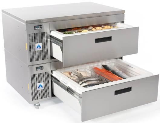
4 1 What is Adande? Welcome to Adande Refrigeration Adande is a new method of cold storage developed as a series of refrigerated drawers that offer storage temperature flexibility in 1ºC increments between 22ºC and +15ºC. Each refrigerated drawer:- Provides stable temperature storage A removable container to act as temporary cool and safe product storage. Gives full plan area access providing space efficient storage. Is easily cleaned or replaced. 2 Adande Explained Adande uses standard technology and refrigeration parts but in a completely new and patented way. A dedicated fridge engine supplies refrigerant to an evaporator coil assembly. The evaporator coil assembly then supplies cooling to the insulated container and is sized to maintain up to 40kg of product at any set point temperature, in the range of 22ºC to +15ºC. Figure 1: Front view of Adande Single Drawer ADE C Page 4 of 45
5 3 EC Declaration of Conformity We declare that the following machinery complies with the essential health and safety requirements of the :- The Machinery Directive 2006/42/EC. The Low Voltage Directive 2006/95/EEC. The Electromagnetic Compatibility Directive 2004/108/EC. The Pressure Equipment Directive 97/23/EC. Machinery Description: 1 Drawer Appliance for Chilled Storage. Make: Adande. Type: Adande unitary drawer refrigeration Manufactured by Adande Refrigeration Ltd., 45 Pinbush Road, South Lowestoft Industrial Estate, Lowestoft, Suffolk NR33 7NL The following transposed harmonised European Standards have been used: EN ISO parts 1 & 2 Safety of Machinery Basic concepts, general principles for design. EN ISO Safety of Machinery Safety distances to prevent danger zones being reached by the upper and lower limbs. EN ISO : 2006 Ergonomics of the thermal environment -- Methods for the assessment of human responses to contact with surfaces -- Part 1: Hot surfaces. EN Food processing machinery Basic concepts Part 2 : Hygiene requirements EN :2001, Electromagnetic compatibility (EMC) - Part 6-3: Generic standards; Emission standard for residential, commercial and light- industrial environments EN Generic Immunity Standard; Residential commercial and light industrial environments. EN The Safety of Household and Similar Electrical Appliances Part 2 24: Particular Requirements for Refrigerating Appliances and Ice Makers. EN :2010 Household and Similar Electrical Appliances Safety - Part 2 89: Particular Requirements for commercial refrigerating appliances with an incorporated or remote refrigerant condensing unit or compressor. The technical file for this machinery will be prepared on demand by :- Name: Ian Wood Position: Managing Director Who also signs on behalf of the manufacturer ADANDE REFRIGERATION 45 Pinbush Road South Lowestoft Industrial Estate Lowestoft Suffolk NR33 7NL. ADE C Page 5 of 45

6 4 Storage of Product For the drawer to operate at full efficiency the heated seal should be maintained in good condition. It is essential that the product is not stored above the MAX FILL LEVEL line as this can damage the seal and affect the operation of the drawer. The drawer is capable of storing any food product. However, products which may give off acidic odours like vinegar, onions, etc should be suitably sealed. Adande also recommends storage containers with liquid food products be stored with lids. Ensure that the product is never stacked above the MAX FILL LEVEL Label in the insulated container. 5 Operating Adande Temperature Control System The Adande temperature control system allows you to set and control the drawer within a temperature range of -22 C ( -8 F) and +15 C (59 F). Temperature accuracy in the drawer will be maintained within ±2ºC of the set point. 5.1 The Display Controls To adjust the temperature set point (figure 2) press and hold the i button, the drawer set point will then be displayed. While holding the i button Increase or decrease temperature using the arrow buttons, on release of both buttons the new set point will be stored. Set temperature Decrease temperature Manual defrost Power On/ Off Increase temperature Figure 2: Adande Display Control Panel ADE C Page 6 of 45
7 5.2 Defrost The refrigeration system automatically defrosts. If a manual defrost is required then press the manual defrost button on the control panel for 3 seconds. 5.3 Drawer Alarm If the drawer is open for more than 3 minutes, the display in the control panel changes to DO DO. When the alarm has been activated, the Adande unit will alarm both visually and audibly. To silence the audible alarm, press ANY button on the display, or close the drawer. The alarm light and flashing display will continue to show until the drawer has been fully closed. NOTE: THERE IS NO COOLING TO THE INSULATED CONTAINER WHEN THE DRAWER IS OPEN. 5.4 Error Alarm If display reads E1 or E2 2, a temperature probe has failed, and an engineer should be called. The Adande drawer will operate with a 10 minute on / 10 minute off cycle in the event of an E1 failure. This will help to maintain the stored product at a safe temperature, but precise temperature control will be lost. E2 will only affect defrosts, and these will be timed to maintain operation of the unit. An engineer should be called as soon as possible for either fault. 5.5 Temperature Alarm If HI should appear on the display, the drawer temperature has exceeded its set point by 7 C and product core temperature should be checked. This alarm may also be triggered if the Adande drawer has recently been turned on, loaded with warm product or left open for a long period of time. If the temperature does not return to the set point temperature, an engineer should be called. If LO should appear on the display, the drawer temperature has fallen below its set point by 7 C and product core temperature should be checked. This alarm may also be triggered if the Adande drawer s temperature set point has recently been increased. If the temperature does not return to the set point temperature, an engineer should be called. ADE C Page 7 of 45
.")

 Push the new display into the front grill and click into position")

8 6 Display Panel Replacement To replace a faulty display panel first isolate the power supply, then remove the front grill, (refer to chapter 11). Next unplug the data ribbon from the back of the controller (figure 3a), then using a flat head screw driver depress the plastic lugs on the display and push the faulty display out of the front grill panel.(figure 3b/3c) Push the new display into the front grill and click into position (figure 3d), finally plug in the new displays data ribbon into the back of the controller, ensuring that it is fully inserted. Figure 3a: Data cable input on controller Figure3b Figure 3c Figure 3d ADE C Page 8 of 45
.")

9 7 Electrical Connection The Adande drawer should be connected to a 230V, single phase, 50 Hz, standard socket outlet supply. The drawer is connected to the mains supply with a detachable supply lead, one end of which is fitted with a standard 13 amp 3 pin plug (fused at 13A). The other end of the supply lead, fitted with an appliance plug, which is connected to the Adande drawer as shown in figure 4a below. Single P clip for retaining mains cable Unique Serial number of the drawer: This should be quoted when requesting a service visit Figure 4a: Mains connection point The unused socket on the right hand side in figure 4a can be used to provide a mains supply to additional Adande drawers as shown in figure 4b below. Figure 4b: Mains connection point DO NOT REMOVE ACCESS PANELS WITH THE ELECTRICAL SUPPLY CONNECTED. ADE C Page 9 of 45
 and +38ºC (100ºF).")


10 8 Location and Stability It is important that the Adande drawer is installed and maintained on a flat, clean and level surface to ensure correct operation. The room should be dry and sufficiently ventilated. Optimum performance is obtained at ambient temperatures between +16ºC (60ºF) and +38ºC (100ºF). The air outlet grill MUST be kept clear at all times to maintain optimum performance. The Adande drawer can be mounted on rubber feet, rollers or castors. When mounted on a castor base, the front two castors should have their brakes ON during normal use as in figure 5. Figure 5: Lockable Castor If the Adande drawer is mounted on two rollers at the rear and rubber feet at the front, then to move the drawer either lift the front as shown in figure 6 and push or pull into position, or use an open drawer as a lever to lift, as shown in figure 7, this method may be preferable if units are stacked more than one high. Figure 6 Figure 7 THE INSULATED CONTAINER SHOULD BE UNLOADED BEFORE MOVING ADE C Page 10 of 45


11 9 Insulated Container Removal For many of the maintenance procedures the insulated container will need to be removed to allow for access. To remove the insulated container, first pull the drawer out fully so that the rear edge of the container clears the front and the runners are fully extended. Then as the photo below shows (figure 8) lift the container vertically up to remove (two people should lift the container out if still filled with product). Figure 8: Removing the insulated container ADE C Page 11 of 45
. Replacement is the reverse of the removal procedure.")

.")
12 10 Worktop Removal To remove the worktop, first remove the 4 off M5 X 8 ST/ST bolts from the rear of the drawer, lift the rear of the worktop and push slightly forward to slide over and clear from the front retaining slots (Figure 9). Replacement is the reverse of the removal procedure. NOTE: CORRECT LIFTING PROCEDURES SHOULD BE FOLLOWED 11 Front Grille Removal Figure 9: Worktop removal To gain access to the electrical components it is necessary to remove the front grille, to do this first remove the insulated container from the drawer, slacken the 2 off M5 X 8 ST/ST bolts located inside the drawer space, and slacken the 2 off M5 X 8 ST/ST screws located externally at the side of the unit. The front grille can now be removed by pulling forward at the bottom and then down. (figure10). NOTE: POWER MUST BE ISOLATED BEFORE REMOVING ANY PANELS Loosen:- 2 x Screws 2 x Bolts Figure 10: Front grille removal ADE C Page 12 of 45


13 12 Left Hand Panel Removal R To gain access to the compressor, the left hand panel must be removed from the drawer, to remove this panel the 4 off M5 X 8 ST/ST screws on the side of the drawer and 2 off M5 X 8 bolts from the rear of the drawer must be removed as shown in figure 11, then slide the panel down and out. Remove 4x screws and 2x bolts 13 Rear Panel Removal Figure 11: LH side fridge engine access panel removal The rear panel of the unit may require removal to gain access to the drain pipe or assist in diffuser and heated seal replacements. To remove the back panel, remove all 13 off M5x10 ST/ST bolts as shown in figure 12 below. Figure 12: Rear panel removal ADE C Page 13 of 45


14 14 Drawer Front Removal To remove the drawer front you will need to remove the 4 off M5 Br.Zn.Pd. Nyloc nuts and 4 off M5 X 10 St/Steel bolts as shown in figure 13 below. NOTE: WHEN REPLACING DRAWER FRONT LOCTITE SHOULD BE USED ON THE SCREWS Figure 13: Removing the four Nyloc Nuts and four M5x10 ST/ST Once these fixings are removed the drawer front will now slide off as shown below in Figure14. Figure 14: Removing the drawer front ADE C Page 14 of 45
. Remove the Spade Connectors from the back of the switch and push the switch through to the drawer cavity as shown in figure 15 and 16.")
15 15 Drawer Switch Replacement To gain access and/or replace the drawer switch, remove either the insulated container and worktop (Chapter 9 and 10) or the Insulated container and side panel (Chapters 9 and 12). Remove the Spade Connectors from the back of the switch and push the switch through to the drawer cavity as shown in figure 15 and 16. Figure 15: Spade connectors connected to the drawer switch Figure 16: Drawer switch mounted on the Inner Wall Side Panel. ADE C Page 15 of 45
.")

16 16 Removing the Diffuser To remove the diffuser the Insulated container will first need removing to allow access (Chapter 9). To remove the diffuser from the lid the 8 off plastic Pozi Drive screws will need removing as in figure 17. This will allow the diffuser to be lowered for access. NOTE: THE DIFFUSER WILL BE CONNECTED TO THE DRAWER BY THE EVAPORATOR FAN WIRES Figure 17: Lid Diffuser ADE C Page 16 of 45


17 17 Evaporator Fan Replacement Once the diffuser is removed, cut the wires at the FAN end and use these to pull through the new fan wires. Now remove the four self-tapping screws that hold the fans in place as shown in figure 18a. The fan wires need to be disconnected from the controller within the controller enclosure, pull the new wires through the hole in the lid, fit bullet crimps to the new fan wires and connect to the controller, mount the fans back on the diffuser as shown below in figure 18b. Replace all cable ties. 4 x Self Tapping screws and cable tie Figure 18a: Evaporator fans Figure 18b ADE C Page 17 of 45
 Once this has been done remove the drain pipe and putty from the back of the lid as shown in figure 19 below.")
 NOTE: ATTACH A SPARE PIECE OF DRAW WIRE TO THE OLD HEATER WIRES BEFORE PULLING WIRES OUT TO AID PULLING THROUGH NEW HEATER WIRES.")
18 18 Drain Tray and Defrost Heater Removal and Replacement To remove the drain tray the insulated container, rear panel and diffuser will need to be removed. (Refer to chapters 9, 13 & 16) Once this has been done remove the drain pipe and putty from the back of the lid as shown in figure 19 below. Now remove the wires for the defrost heater from the controller. (Refer to Chapters 24 and 25) NOTE: ATTACH A SPARE PIECE OF DRAW WIRE TO THE OLD HEATER WIRES BEFORE PULLING WIRES OUT TO AID PULLING THROUGH NEW HEATER WIRES. Remove the 4 off M5 X 10 bolts and associated sealing washers fixing the drain tray to the evaporator, drop down the drain tray complete with defrost heater and remove. (Figure 20) Figure 19: Drain pipe and putty Figure 20: Remove four bolts and sealing washers to release drain tray NOTE: When replacing the drain tray take care not to bend the tray or the water may not drain correctly, ensure all four sealing washers are on the four fixing bolts. Replace drain tray and putty around drain pipe penetration both inside and outside of lid. ADE C Page 18 of 45
 to gain access to the evaporator coil. Remove the P-Clips holding the probe in place and the refrigeration putty from wire penetration in the lid.")
19 19 Evaporator Temperature Probes Replacement To replace a faulty temperature probe the insulated container, drawer front, diffuser and drain tray will need to be removed. (Refer to chapters 9, 14, 16 & 18) to gain access to the evaporator coil. Remove the P-Clips holding the probe in place and the refrigeration putty from wire penetration in the lid. Disconnect the faulty probe from the controller and use it as a pull through to Install the new probe back through the electrical wire penetration hole in the lid, then reconnect to controller, replace the P-Clips and refrigeration putty, as shown in figure 21. T1 Drawer Temperature probe T2 Defrost probe Replace Refrigeration Putty Figure 21: Temperature probes held in place with P-Clips ADE C Page 19 of 45
20 20 Heated Seal Replacement To replace the seal first remove the insulated container (Chapter 9). Then pull the heated seals wires through the inner wall from the compressor housing into the drawer cavity and disconnect the two bullet connecters; this disconnects the heating element from the 12v power supply. Pull the seal out of the retaining channel in the lid and replace with a new seal (Push seal into corners of the retaining channel first for alignment). Reconnect the Bullet connectors and pass back through the Inner Wall into the compressor housing to prevent it snagging on the drawer or runner when closed. On completion of seal replacement the lid height should be checked refer to Chapter 21. Figure 22: Heated seal wires and Inner wall penetration ADE C Page 20 of 45


21 21 Seal Height Adjustment The seal and lid height is critical to ensure: The correct closure and opening of the drawer To prevent the insulated container icing closed To prevent access of warm ambient air into the container Lid Height adjustment is done by loosening the 4 lid mounting screws, 2 are located behind removable caps on the RH side panel and 2 within the compressor housing (as shown below with the worktop removed in figures 23a and b). The two rear corners should be adjusted first, apply a small amount of pressure and tighten, then adjust the two front corners by loosening the screws and letting the lid rest under its own weight. To adjust the lid height on a drawer that is stacked, while the screwdriver is located in the screw head lever the lid up or down as required, repeat the process for all screws until the desired height is achieved. NOTE: DO NOT OVER COMPRESS THE SEAL To check that the seal isn t over compressed, open the drawer and ensure there is a 2mm gap between the back edge of the insulated container and the front edge of the seal (container and runners are at a slight angle to the lid). To prevent a new seal sticking to the rim of the insulated container it is recommended that the seal is lubricated with a silicone based plastic/ rubber lubricant. Lid mounting screws Figure 23a and b: Lid mounting screws when worktop is removed ADE C Page 21 of 45
.")
 and the four off M5x8 (two off on")


22 22 Runner Replacement To replace a drawer runner the Insulated container and drawer front will need to be removed to gain access (Chapters 9 & 14). First remove the container support from the failed runner by removing the M5 X 6 ST/ST countersink screw (figure 24) and the four off M5x8 (two off on right hand side and two off on left hand side) holding the brace container support rear (figure 24.1) the drawer support can now be removed by lifting the front of the support and pulling forward to detach it from the lancings on the runner inner beam. (Figure: 25) Figure 24: Remove container support retaining screw Figure 24.1: Brace Conatiner Support Rear and four off M5x8 Figure 25: Removal of container support from the drawer runner. ADE C Page 22 of 45


23 The runner can now be removed from the drawer, extend the runner slightly, and with a firm grip twist the runner toward the middle of the drawer, this will allow the front of the runner to be lifted clearing the front fastenings, pull the runner forward to clear the rear fixing. See figures below. Figure 26a: Twist runner. Figure 26b: Lift and pull forward Figure 26c: Fixings in vertical wall supports and lancings in runner outer beam Replacing the runner is the reverse of the removal procedure, engage the rear lancing of the runner in the back vertical wall support and push horizontally to fully engage the rear lancing, engage the middle and front lancings in their associated vertical wall supports and press down on the runner sharply, it should engage in the front vertical wall support with a CLICK, you should now not be able to lift the front of the runner vertically. Fit the container support in the same way by engaging the rear fixing first with a horizontal motion then engage the front 2 lancing s and press down to fully engaging both, ensure the hole in the front of the runner lines up with the hole in the container support, and refit the M5 X 6 countersink screw, once you have done this you will also need to refit the brace container support rear with four off M5x8 bolts. If required the runner can be lightly greased with food grade grease. ADE C Page 23 of 45
. Reverse this to replace the fan and connect to the controller.")

24 23 Condenser Fan Replacement To replace the condenser fan, the front grille will need to be removed (Chapter 11). First remove the two loomed wires that run through the 6.4mm grommet to the controller. Then remove the four fixing screws and remove the fan (figure 27). Reverse this to replace the fan and connect to the controller. (Refer to chapter 25 Electrical Control System) 24 Electrical components 4 Off M4 X 45 Br.Zn.Pd. Screws Figure 27: Condenser Fan mounting Each Adande drawer is fitted with a 5 amp fuse in the 240v mains supply to the controller, this fuse and holder is situated adjacent to the controller (Figure 28) and is accessed by removal of the front grille (Chapter 11). Neutral block 12 volt power Supply 6.3 amp fuse Display Figure 28: Electrical components ADE C Page 24 of 45
25 25 Electrical Control System If replacing items connected to the Adande Controller then please refer to the tables below. NOTE: ALL NEUTRAL CONNECTIONS NS GO TO THE NEUTRAL PORTS Adande Controller 1 Defrost temperature probe 2 Defrost temperature probe 3 Drawer temperature probe 4 Drawer temperature probe 5 Drawer switch 6 Drawer switch 7 Defrost heater live 8 Compressor live 9 Condenser fan live v live in 11 Spare live 240v 12 Neutral 13 Neutral 14 Neutral 15 Neutral 16 Neutral 17 Neutral 12v outlet (evaporator fans and seal) 18 Live 12v outlet (evaporator fans and seal) ADE C Page 25 of 45
26 25.1 Wiring diagram ADE C Page 26 of 45
27 26 Settings for ACON-ADSP ADSP-RE RE-01 Controller 26.1 R404a controller settings. The Settings menu is accessed by pressing the 2 outer buttons X + i for 5 seconds Code Setting Description Code Setting SCL 1.0'C Readout scale FT1 0 SPL -22 SPH 15 SP 3.2 Min temperature set point Max temperature set point Effective temperature set point HYS 1 Thermostat hysteresis ALR -7 CRT 3 Compressor rest time AHR 7 CT1 5 CT2 5 CSD 1 Compressor run time with sensor T1 failure Compressor off time with sensor T1 failure Compressor stop delay from door opening Description Fan stop delay after comp stop FT2 0 Timed fan stop FT3 0 Timed fan run ATM REL Alarm thresholds ATD 60 Low temp alarm differential High temp alarm differential Delay before alarm warning ADO 3 Drawer alarm delay ACC 0 Periodic condenser cleaning DFR 4 Defrosting frequency/24h SB YES Button (0/1) enabling DLI 8 Defrost end temperature DS YES Drawer switch enabling DTO 25 Max defrost duration LSM Non Light control mode DTY ELE Defrost type OS1 0 Probe 1 offset DRN 6 Drain down time T2 YES Probe 2 enabling DDY 30 Defrosting display control OS2 0 Probe 2 offset FID No Fans active during Delay for min/max temp. TLD 5 defrost logging FDD -5 Fan restart temp after defrost SIM 100 Display slowdown FTC NO Evaporator fan timed Address for PC ADR 1 out communication ADE C Page 27 of 45
28 26.2 R600a controller settings Code Setting Description Code Setting SCL 1.0'C Readout scale FT1 0 SPL -22 SPH 15 SP 3.2 Min temperature set point Max temperature set point Effective temperature set point HYS 2 Thermostat hysteresis ALR -7 CRT 5 Compressor rest time AHR 7 CT1 10 CT2 10 CSD 2 Compressor run time with sensor T1 failure Compressor off time with sensor T1 failure Compressor stop delay from door opening Description Fan stop delay after comp stop FT2 0 Timed fan stop FT3 0 Timed fan run ATM REL Alarm thresholds ATD 60 Low temp alarm differential High temp alarm differential Delay before alarm warning ADO 3 Drawer alarm delay ACC 0 Periodic condenser cleaning DFR 4 Defrosting frequency/24h SB YES Button (0/1) enabling DLI 8 Defrost end temperature DS YES Drawer switch enabling DTO 25 Max defrost duration LSM Non Light control mode DTY ELE Defrost type OS1 1 Probe 1 offset DRN 6 Drain down time T2 YES Probe 2 enabling DDY 30 Defrosting display control OS2 0 Probe 2 offset FID No Fans active during Delay for min/max temp. TLD 5 defrost logging FDD -5 Fan restart temp after defrost SIM 100 Display slowdown FTC NO Evaporator fan timed Address for PC ADR 1 out communication ADE C Page 28 of 45
29 27 Refrigeration maintenance A standard hermetically sealed R404a vapour compression refrigeration circuit is used in the Adande drawer system and will need minimum maintenance. PARTS LIST Ref Part No Description Accumulator Compressor Condenser Condenser fan Filter drier Evaporator Evaporator Fan Electric Defrost Heater TC Temperature control probe DT Defrost termination probe OS Open (drawer) switch RC Refrigeration contoller RC REFRIGERATION CONTROLLER OS Open drawer Switch TC 06 Suction Line / Liquid Heat Exchange DT Schraeder access valve 01 Condenser and Compressor E 08 Evaporator and Drain Figure 29: Refrigeration circuit diagram STANDARD UNITARY The unique design for airflow over the condenser means that the majority of any airborne contaminants are deposited on the easily cleaned surfaces of the drawer cabinet and the insulated container. In the unlikely event of the condenser becoming blocked, it can be easily accessed by removing the insulated container and cleaned in the normal way. ADE C Page 29 of 45

30 28 Drawer configurations The Adande Side Engine Drawer Fridge (VCS) can be configured in several ways. Below are some examples of single, two and three drawer options. VCS1HCHS Single drawer High castor base Heat shielding worktop This arrangement is intended to support a grill or oven. VCS2CT Two drawer Standard castor base Top cover The top cover is a non load bearing cover. This arrangement is intended for under counter installations VCS3CW Three drawer setup Castor base Worktop ADE C Page 30 of 45

 Blast Chiller")

31 VCS2CM Two drawer unit Castor base Microwave station (Optional can opener) Blast Chiller drawer Lockable drawer front ADE C Page 31 of 45
32 29 Fault Finding ing 29.1 Drawers not operating correctly Possible Cause Recommended Action Runners require lubrication Lubricate runners, see Chapter 22 Runners are mechanically damaged Replace runners, see Chapter 22 Seal is being over compressed Readjust lid height, see Chapter 21 Ice build up causing diffuser to hit insulated container Check defrost heater operation and drain for blockages see Chapter 18 Check seal height see Chapter Seal and/or insulated container rim have ice and condensation Possible Cause Recommended Action Seal is contaminated Clean the seal Seal damaged Replace seal, see Chapter 20 Seal heater is not working a) Check 12 v power supply b) Check seal heater continuity, Replace seal if faulty, see Chapter 20 Seal compression is inadequate Readjust lid height, see Chapter 21 Product/packaging trapped Ensure stored product is below Max Fill between insulated container rim line in insulated container. and lid distorting seal 29.3 Drawer is not maintaining set temperature Possible Cause Failure of evaporator fans Seal failure Excessive icing of evaporator coil Drawer temperature probe faulty Defrost termination probe faulty Blocked capillary line Low refrigerant Failure of condenser fan Condenser coil is blocked Failure of compressor Recommended Action a) Check drawer switch operation b) Check 12v power supply c) Check evaporator fans. Replace evaporator fans if necessary, see Chapters 15, 16, and 17 Check condition of heated seal a) Check defrost operation b) Check defrost heater operation c) Manually defrost d) Check/clean drain from evaporator e) Check seal condition f) Check lid height Replace temperature probe Replace temperature probe Replace capillary tube. Search for leak in system, repair leak and recharge with refrigerant Check the condenser fan is operational, see Chapter 23 Clean condenser coil Replace compressor if faulty. ADE C Page 32 of 45
33 29.4 The Drawer does not power up Possible Cause Fuse has failed in mains plug Fuse has failed within electrical system No mains power at mains terminals Plug into drawer not fully inserted Recommended Action Check fuse, if it has failed investigate for possible cause before fitting new 13A fuse. Check internal 5 amp fuse see Chapter 24 If mains fuse OK then check wiring of the plug. Ensure power is switched off at socket. Check all plugs/ sockets, ensure P clips correctly fitted Evaporator fans run when drawer is open Possible Cause Controller has failed. Recommended Action Replace Controller 29.6 Evaporator fans do not run when drawer is closed Possible Cause Drawer switch has failed 12 v power supply in control module failed Recommended Action Replace switch Check 12v power supply in controller module Check wiring to fans for damage 29.7 Display not functioning Possible Cause Ribbon cable connections loose Fuse has failed within unit Display has failed Recommended Action Check ribbon cable connections at display and controller Check 6.3amp fuse in controller Replace display ADE C Page 33 of 45
34 30 Exploded diagrams 30.1 Housing spare parts Item Part No. Description PANEL HOUSING BASE PANEL HOUSING LH BRACE CONTAINER SUPPORT REAR PANEL HOUSING REAR PANEL FAN MOUNTING PANEL LOWER CONTROLS BRACKET CONDENSER SUPPORT COMMON WALL ASSEMBLY SUPPORT RH ADANDE CONTAINER Item Part No. Description DRAWER SLIDE RH PLUG BUTTON SNAP-IN PANEL HOUSING RH ASSY CHANNEL UPPER FRONT RECESSED PLASTIC DRAWER PULL DRAWER FRONT FIXED ASSY SUPPORT LH ADANDE CONTAINER PANEL CONTROLLER & LOUVRE DRAWER SLIDE LH ADE C Page 34 of 45
35 30.2 R404a & R600a Fridge, Electrical System and Drawer Parts Item Part No. Description COMPRESSOR EMT2117GK COMPRESSOR NBU1118Y (evcs) EVAPORATOR TRAY (VCS) EVAPORATOR TRAY (evcs) POWER OUTLET IEC POWER INLET IEC DRAIN PIPE HARNESS MAIN POWER INTERNAL HARNESS SWITCH & SEAL HEATER Item Part No. Description DRAWER SWITCH INSULATED LID BUILT ASSEMBLY INSULATED CONTAINER CONTROLLER DISPLAY AXIAL FAN FILTER DRIER REFRIGERATION CONTROLLER CONDENSER ADE C Page 35 of 45
36 30.3 Insulated Lid (part No Complete Assembly) ADE C Page 36 of 45
37 30.4 C - BASE - Standard Castors (Part No complete assembly) Item Part No. Description SWIVEL CASTOR 75mm WITH BRAKE SWIVEL CASTOR 75mm PANEL COUNTERBALANCE PANEL BASE CASTOR TROLLEY ADE C Page 37 of 45
38 30.5 HC BASE - High Castors (Part No complete assembly) Item Part No. Description SWIVEL CASTOR 125mm WITH BRAKE SWIVEL CASTOR 125mm PANEL COUNTERBALANCE PANEL BASE CASTOR TROLLEY ADE C Page 38 of 45
39 30.6 SC BASE - Small Castors (Part No complete assembly) Item Part No. Description SWIVEL CASTOR BRAKED 50mm SWIVEL CASTOR 50mm PANEL COUNTERBALANCE PANEL BASE 50mm CASTOR TROLLEY ADE C Page 39 of 45
40 30.7 DC- BASE - Double Castor with Adapter (Part No complete assembly) Item Part No. Description SWIVEL CASTOR DOUBLE WHEEL BRAKED BRACKET ADAPTER CASTOR FITTING SWIVEL CASTOR DOUBLE WHEEL PANEL COUNTERBALANCE PANEL BASE CASTOR TROLLEY ADE C Page 40 of 45
41 30.8 R BASE - Rollers rear, Feet front (Part No complete assembly) Item Part No. Description FOOT SUPPORT 50MM ASSEMBLY ROLLER ASSEMBLY PANEL COUNTERBALANCE PANEL BASE CASTOR TROLLEY ADE C Page 41 of 45
42 30.9 SR BASE - Small Rollers rear, Small Feet F front (Part No complete assembly) Item Part No. Description FOOT SUPPORT 40MM ASSEMBLY ROLLER SMALL ASSEMBLY PANEL COUNTERBALANCE PANEL BASE CASTOR TROLLEY ADE C Page 42 of 45
43 30.10 T - Top cover Item Part No. Description TOP COVER ADE C Page 43 of 45
44 W - Worktop (shown with optional 50mm upstand) Item Part No. Description WORKTOP UPSTAND ADE C Page 44 of 45
45 HS - Heat shield top Item Part No. Description HEAT SHIELD TOP ADE C Page 45 of 45
Operations Manual VCS/VCR/VLS
 Operations Manual VCS/VCR/VLS Contents Page 1 What is the Adande System 3 2 Adande Technology Explained 3 3 EC Declaration of Conformity 4 4 Storage of Product 5 5 Operating Adande - Temperature Settings
Operations Manual VCC
 Operations Manual VCC Contents Page 1 What is the Adande System 3 2 Adande Technology Explained 3 3 EC Declaration of Conformity 4 4 Storage of Product 5 5 Operating Adande Temperature Settings 5 5.1 The
BSD SERIES REFRIGERATORS AND FREEZERS Installation, Operation and Maintenance Instructions
 BSD SERIES REFRIGERATORS AND FREEZERS Installation, Operation and Maintenance Instructions INSPECTION When the equipment is received, all items should be carefully checked against the bill of lading to
TRUE TEMPERATURE CONTROLS SEQUENCE OF OPERATION
 28 Control version will vary with model and age of cabinet. LAE: t1 = Thermostat t2 = Defrost t3 = Display t3 probe is not installed and / or activated in all applications if t3 is not installed and /
COMMERCIAL REFRIGERATORS, STAINLESS STEEL PRODUCTS OPERATING INSTRUCTIONS
 COMMERCIAL REFRIGERATORS, STAINLESS STEEL PRODUCTS OPERATING INSTRUCTIONS CE COMMERCIAL REFRIGERATORS Model - S.N.: Volt: 220 Hz: 50 Amps: Watt: Watt (heating element): Fuse Amps: Refrigerant: R gr: Working
Service Manual. Slimline Range With LF28 Controller ISO ISO 9001
 Service Manual Slimline Range With LF28 Controller ISO 14001 ISO 9001 Re-Issued Version July 2010 Contents Manual Information & Health & Safety Notes 1 Environmental Management Policy 2 Disposal Requirements
Service Manual. LC125 Meatwell with LDU15 Controller (Feb 04 till July 09) then AT1-5 Controller (July 09 onwards)
 then AT1-5 Controller (July 09 onwards)") Service Manual LC125 Meatwell with LDU15 Controller (Feb 04 till July 09) then AT1-5 Controller (July 09 onwards) ISO 14001 ISO 9001 Re-Issued October 2010 Original Aug 09 Contents Manual Information &
Service Manual LC125 Meatwell with LDU15 Controller (Feb 04 till July 09) then AT1-5 Controller (July 09 onwards) ISO 14001 ISO 9001 Re-Issued October 2010 Original Aug 09 Contents Manual Information &
TABLE OF CONTENTS. 1. Technical specifications of the appliance 2
 TABLE OF CONTENTS Pages 1. Technical specifications of the appliance 2 a. Refrigerated counter 2 b. Upright refrigerator 3 c. Open top refrigerated counter 3 d. Pizza refrigerated counter 4 e. Pizza refrigerated
0LLCD003EN STANDBY NORMAL INFO MENU INFO DATA SETUP MENU PARAMETER VALUE. Not Product Air Display scale Operating Temper. (sim.
 0LLCD003EN LCD15 Thank you for having chosen an LAE electronic product. Before installing the instrument, please read this instruction booklet carefully in order to ensure safe installation and optimum
FHHT 18 3 PHASE /32A / 400V ELECTRIC HEATER PRODUCT MANUAL P
 FHHT 18 3 PHASE /32A / 400V ELECTRIC HEATER PRODUCT MANUAL P 1 of 13 These instructions should be read by: The specifying engineer. The installation engineer. The user. The service engineer. WARNINGS Failure
New LAE controller for Plug-in cabinets
 From: Lonardi [MC] To: Price-list owners Ref.: P-6.006/01 Date: 19/03/01 New LAE controller for Plug-in cabinets Dear Sirs, with the aim of a continuous improvement we are going to introduce our new LAE
Original Service Manual
 Cabinets & Counter Models FD2-10 Controller with LCD5S Display Original Service Manual English A Division of ITW Ltd March 2014 Issue 1 Foster Refrigerator Oldmedow Road King s Lynn Norfolk, PE30 4JU United
FW821 extra large integrated larder fridge Manual for Installation, Use and Maintenance
 FW821 extra large integrated larder fridge Manual for Installation, Use and Maintenance 1 Customer Care Department The Group Ltd. Harby Road Langar Nottinghamshire NG13 9HY T : 01949 862 012 F : 01949
PRO A CABINET & COUNTER
 PRO A CABINET & COUNTER ISO 14001 ISO 9001 Contents Environmental Management Policy 1 Disposal Requirements 1 Cabinet description 2 Controller Operation 2 to 4 Information Menu 4 Parameter Setting and
Telephone Helpline: (Australia) Blast Chiller / Freezer. Instruction Manual. Model DN492-A DN494-A
 Blast Chiller / Freezer. Instruction Manual. Model DN492-A DN494-A") Blast Chiller / Freezer Instruction Manual Model DN492-A DN494-A 1 Safety Tips Position on a flat, stable surface. A service agent/qualified technician should carry out installation and any repairs if
Blast Chiller / Freezer Instruction Manual Model DN492-A DN494-A 1 Safety Tips Position on a flat, stable surface. A service agent/qualified technician should carry out installation and any repairs if
FW422 Integrated In Column Larder Fridge Manual for Installation, Use and Maintenance
 FW422 Integrated In Column Larder Fridge Manual for Installation, Use and Maintenance 1 Customer Care Department The Group Ltd. Harby Road Langar Nottinghamshire NG13 9HY T : 01949 862 012 F : 01949 862
Service Manual. Slimline Range with FD2-10 Controller ISO ISO 9001
 Service Manual Slimline Range with FD2-10 Controller ISO 14001 ISO 9001 Issued August 2010 Contents Manual Information & Health & Safety Notes 1 Environmental Management Policy 2 Disposal Requirements
FlexDrawer. Original Service Manual. FFC6-2, 3-1, 4-2 & 2-1 Models. FD2-10 Controller & LCD5S Display. English
 FlexDrawer FFC6-2, 3-1, 4-2 & 2-1 Models FD2-10 Controller & LCD5S Display English ISO 9001 February 2016 Issue 1 ISO 14001 A Division of ITW Ltd Foster Refrigerator, Oldmedow Road, King s Lynn, Norfolk,
FDM Series. User Manual. SKOPE Food Display Cabinet Integral models: FDM900i/1200i/1500i. Model FDM1200i
 FDM Series SKOPE Food Display Cabinet Integral models: FDM900i/1200i/1500i Model FDM1200i MAN2056O Rev 2.0 Aug. 2010 Integral models: FDM900i/1200i/1500i SKOPE Food Display Cabinet MAN2056O Rev 2.0 Aug
CABINET PARTS For Model: KSSC42QVS03 (Stainless Steel)
") CABINET PARTS 42" BUILT IN REFRIGERATOR 2 12 Litho In U.S.A. (wlc)(bay) 1 Part No. Rev. A CABINET PARTS 1 Literature Parts W10303989 Use & Care Guide W10205643 Energy Guide W10159832 Service & Wiring Sheet
CABINET PARTS 42" BUILT IN REFRIGERATOR 2 12 Litho In U.S.A. (wlc)(bay) 1 Part No. Rev. A CABINET PARTS 1 Literature Parts W10303989 Use & Care Guide W10205643 Energy Guide W10159832 Service & Wiring Sheet
Environmental Management Policy for Service Manuals and Duets.
 Packaged Coldroom 0 Contents Page Environmental Management Policy 1 Disposal Requirements 1 Introduction 2 Control Panel 2 LCD 28 Controller With LCD 16 Display used on All Rooms From E5167380 From Feb
User Manual. SKOPE Backbar, Counterline & Slimline BB, CL & CC Series. 1, 2 & 3 Door Horizontal Chillers. MAN11015 Rev. 2.0 Feb.
 BB, CL & CC Series 1, 2 & 3 Door Horizontal Chillers CL400 BB580 MAN11015 Rev. 2.0 Feb. 2015 CL800 SKOPE Warranty Protection Register now for peace of mind It s quick and simple. Take a few minutes to
MFC501 & MFC701. Manual for installation, use and maintenance. Integrated fridge-freezers. year.
 Manual for installation, use and maintenance MFC501 & MFC701 Integrated fridge-freezers year parts + 1 year labour guarantee www.matrixappliances.co.uk Important The CDA Group Ltd cannot be held responsible
TECHNICAL INFORMATION Touchtronic Clothes Dryers
 TECHNICAL INFORMATION Touchtronic Clothes Dryers Includes: T1302, T1303, T1322, T1329ci T1403 & T1405 2004 Miele This page intentionally left blank. Table of Contents GENERAL INFORMATION A. Warning and
Original Service Manual
 Original Service Manual model name added here By Appointment to Her Majesty Queen Elizabeth II Suppliers of Commercial Refrigeration Foster Refrigerator, King s Lynn BIT25 Controller & LCD5S Display English
SCN60 Residential Nugget Ice Machine
 SCN60 Residential Nugget Ice Machine SCN60 Nugget Ice Nugget Ice What it isn t: Ice frozen in a mold What it is: A chewable ice, formed continuously by forcing soft ice thru tapered holes. Components Compared
Installation & Operations Manual. Master-Bilt Products 908 Highway 15 North New Albany, MS Phone: (800) REV: LN PN
 REV: LN PN") Installation & Operations Manual Master-Bilt Products 908 Highway 15 North New Albany, MS 38652 Phone: (800) 684-8988 REV: LN PN 297-90000 2 TABLE OF CONTENTS INTRODUCTION.. 4 STORE CONDITIONS..... 4 WARNING
Installation & Operations Manual Master-Bilt Products 908 Highway 15 North New Albany, MS 38652 Phone: (800) 684-8988 REV: LN PN 297-90000 2 TABLE OF CONTENTS INTRODUCTION.. 4 STORE CONDITIONS..... 4 WARNING
FF820 Freestanding Full Height Larder Fridge Manual for Installation, Use and Maintenance
 FF820 Freestanding Full Height Larder Fridge Manual for Installation, Use and Maintenance Customer Care Department The Group Ltd. Harby Road Langar Nottinghamshire NG13 9HY T : 01949 862 012 F : 01949
FF820 freestanding full height larder fridge Manual for Installation, Use and Maintenance
 FF820 freestanding full height larder fridge Manual for Installation, Use and Maintenance 1 Customer Care Department The Group Ltd. Harby Road Langar Nottinghamshire NG13 9HY T : 01949 862 012 F : 01949
PC87 American Style Double Door Fridge Freezer Manual for Installation, Use and Maintenance
 PC87 American Style Double Door Fridge Freezer Manual for Installation, Use and Maintenance 1 Customer Care Department The Group Ltd. Harby Road Langar Nottinghamshire NG13 9HY T : 01949 862 012 F : 01949
BLG-HGP Model Bottom Mounted Full-Length Swing Glass Door Freezer Merchandisers
 Installation & Operations Manual for BLG-HGP Model Bottom Mounted Full-Length Swing Glass Door Freezer Merchandisers 2 TABLE OF CONTENTS INTRODUCTION..... 4 STORE CONDITIONS........ 4 WARNING LABELS AND
2 Drawer Vehicle Storage System
 2 Drawer Vehicle Storage System Part No 51000 Installation: Includes: Mounting Kit: 4 x bolts 4 x washers 4 x locking nuts 1 Remove right hand side top section by undoing the 10 retaining screws and set
Installation & Operations Manual Master-Bilt Products 908 Highway 15 North New Albany, MS Phone: (800)
") Installation & Operations Manual Master-Bilt Products 908 Highway 15 North New Albany, MS 38652 Phone: (800) 684-8988 6/17Rev. E 57-02410 6/17 Rev. E 57-02410 2 TABLE OF CONTENTS INTRODUCTION.... 4 STORE
Installation & Operations Manual Master-Bilt Products 908 Highway 15 North New Albany, MS 38652 Phone: (800) 684-8988 6/17Rev. E 57-02410 6/17 Rev. E 57-02410 2 TABLE OF CONTENTS INTRODUCTION.... 4 STORE
CABINET PARTS For Model: JS42CXFXDB00 (Etched Aluminum)
") CABINET PARTS 42" BUILT IN REFRIGERATOR 1 08 Litho In U.S.A. (mat) 1 Part No. Rev. A CABINET PARTS 1 Literature Parts W10151251 Use & Care Guide W10164079 Energy Guide W10159831 Service & Wiring Sheet
CABINET PARTS 42" BUILT IN REFRIGERATOR 1 08 Litho In U.S.A. (mat) 1 Part No. Rev. A CABINET PARTS 1 Literature Parts W10151251 Use & Care Guide W10164079 Energy Guide W10159831 Service & Wiring Sheet
Multideck Display Cabinets
 Multideck Display Cabinets Slim 700, 900, 1200, 1500 & 1800 RF & NG Models Pro 900, 1200, 1500 & 1800 RF & NG Models AD2-28 Controller & RU33 Display English Aug 2012 Version 1 ISO 9001 Original Service
CABINET PARTS For Models: JC2225GEKB13 (Black)
") CABINET PARTS REFRIGERATOR 5 09 Printed In U.S.A. (mat) (psw) 1 Part No. Rev. A CABINET PARTS 1 Literature Parts 12842135SP Use and Care Guide 12893051 Tech Sheet 2 Cover, Hinge (FC) W10175447 Black 3
CABINET PARTS REFRIGERATOR 5 09 Printed In U.S.A. (mat) (psw) 1 Part No. Rev. A CABINET PARTS 1 Literature Parts 12842135SP Use and Care Guide 12893051 Tech Sheet 2 Cover, Hinge (FC) W10175447 Black 3
Telephone Helpline: (Australia) Blast Chiller / Freezer. Instruction Manual. Model DN492-A DN494-A
 Blast Chiller / Freezer. Instruction Manual. Model DN492-A DN494-A") Blast Chiller / Freezer Instruction Manual Model DN492-A DN494-A Safety Tips Position on a flat, stable surface. A service agent/qualified technician should carry out installation and any repairs if required.
Blast Chiller / Freezer Instruction Manual Model DN492-A DN494-A Safety Tips Position on a flat, stable surface. A service agent/qualified technician should carry out installation and any repairs if required.
FWC152 / FWC302 / FWC602 / FWC622 Wine Coolers
 FWC152 / FWC302 / FWC602 / FWC622 Wine Coolers Manual for Installation, Use and Maintenance Customer Care Department The Group Ltd. Harby Road Langar Nottinghamshire NG13 9HY T : 01949 862 012 F : 01949
SKOPE PEGASUS PG Vertical Series. Chillers and Freezers PG600VC PG1300VC. User Manual
 SKOPE PEGASUS PG Vertical Series Chillers and Freezers PG600VC PG1300VC MAN2787 Rev. 4.0 Nov. 2013 SKOPE Warranty Protection To activate your Warranty Protection, you must register your product with SKOPE
FWC152, FWC303, FWC603 & FWC623 Wine Coolers Installation, Use and Maintenance
 FWC152, FWC303, FWC603 & FWC623 Wine Coolers Installation, Use and Maintenance Customer Care Department The Group Ltd. Harby Road Langar Nottinghamshire NG13 9HY T : 01949 862 012 F : 01949 862 003 E :
FWC153, FWC304, FWC604 & FWC624
 FWC153, FWC304, FWC604 & FWC624 Wine Coolers Installation, use and maintenance www.cda.eu Important The CDA Group Ltd cannot be held responsible for injuries or losses caused by incorrect use or installation
fwc152 / fwc303 / fwc603 / fwc623 Wine Coolers Manual for Installation, Use and Maintenance
 fwc152 / fwc303 / fwc603 / fwc623 Wine Coolers Manual for Installation, Use and Maintenance Customer Care Department The Group Ltd. Harby Road Langar Nottinghamshire NG13 9HY T : 01949 862 012 F : 01949
KELVINATOR REFRIGERATORS NO FROST H & SH SERIES
 ELECTROLUX HOME PRODUCTS PTY LTD ABN 51 004 762 341 PRINT POST APPROVED PP565001/00099 Issue: 1 Technical Publication Nº RE 78 Book C26 Date: 1/04 WEB SITE ADDRESS: www.partnship.com.au KELVINATOR REFRIGERATORS
Product Catalogue. Cooler by Design
 Product Catalogue Cooler by Design 1 PRICE LIST INDEX IMPORTANT INFORMATION BLAST CHILL DRAWERS COMPACT DRAWER UNITS Blast chill drawers...page 3 Compact drawer units...page 3 WHEN DESIGNING YOUR KITCHEN
EBAC MODEL WM150 INDUSTRIAL DEHUMIDIFIER OWNER S MANUAL
 EBAC MODEL WM150 INDUSTRIAL DEHUMIDIFIER OWNER S MANUAL WM150 OWNERS MANUAL Page 1 of 9 INTRODUCTION Designed for a wide range of applications, the WM150 is a rugged, industrial unit, which utilizes an
CABINET PARTS For Model: KSSC42QTS02 (Stainless Steel)
") CABINET PARTS 42" BUILT IN REFRIGERATOR 10 11 Litho In U.S.A. (jdc)(psw) 1 Part No. Rev. A 1 Literature Parts W10161714 Use & Care Guide W10164072 Energy Guide W10159832 Service & Wiring Sheet 2306424
CABINET PARTS 42" BUILT IN REFRIGERATOR 10 11 Litho In U.S.A. (jdc)(psw) 1 Part No. Rev. A 1 Literature Parts W10161714 Use & Care Guide W10164072 Energy Guide W10159832 Service & Wiring Sheet 2306424
Service Manual. ETL Blast Chiller Series
 Service Manual ETL Blast Chiller Series September, 2012 2 Customer Service: (800) 333-5653, www.thermalrite.com Safety Precautions THIS MANUAL HAS BEEN PREPARED FOR PERSONNEL QUALIFIED TO INSTALL, MAINTAIN
FWC860 Wine Cooler Installation, Use and Maintenance
 FWC860 Wine Cooler Installation, Use and Maintenance Customer Care Department The Group Ltd. Harby Road Langar Nottinghamshire NG13 9HY T : 01949 862 012 F : 01949 862 003 E : customer.care@cda.eu W :
FW422. Integrated In Column Larder Fridge. Installation, use and maintenance.
 FW422 Integrated In Column Larder Fridge Installation, use and maintenance www.cda.eu Contents: 3 Important information 5 Important safety warnings 6 Before first use 7 Setting the temperature 7 Guidance
Operating Instructions Wine storage refrigerator 12/
 Operating Instructions Wine storage refrigerator 12/98 7080641 1 The wine storage refrigerator you have purchased differs from normal refrigerators in that it is suitable for long-term storage of wine.
HAIER. Full Size Top Mount Refrigerator Training Presentation
 HAIER Full Size Top Mount Refrigerator Training Presentation HAIER CAMDEN, SC Manufacturing Facility TYPICAL TOP MOUNT Run Numbers Always use run numbers when ordering parts Example: HTE18WNAWW-05 Model
Service Manual. EPrem Cabinets & Counters with FD2-10 Controller ISO ISO 9001
 Service Manual EPrem Cabinets & Counters with FD2-10 Controller ISO 14001 ISO 9001 Issued August 2010 Contents Manual Information & Health & Safety Notes 1 Environmental Management Policy 2 Disposal Requirements
Mobile Air Conditioner Instruction Manual Model TC-N9KM
 Mobile Air Conditioner Instruction Manual Model TC-N9KM Please read and retain these instructions for future reference SPECIFICATION Model no. Cooling capacity Power/Ampere consumption for cooling* Air
INSTALLATION. Glass Panel Doors (select models) CAUTION
 CAUTION") Location Do not install refrigerator near oven, radiator or other heat source. If not possible, shield refrigerator with cabinet material. Do not install where temperature falls below 55 F (13 C) or rises
Location Do not install refrigerator near oven, radiator or other heat source. If not possible, shield refrigerator with cabinet material. Do not install where temperature falls below 55 F (13 C) or rises
CABINET PARTS For Model: JS48NXFXDW03 (Base Model)
") CABINET PARTS 48" BUILT IN REFRIGERATOR 2 12 Litho in U.S.A. (wlc)(bay) 1 Part No. Rev. A CABINET PARTS 1 Literature Parts W10303992 Use & Care Guide W10246794 Energy Guide W10483325 Service & Wiring Sheet
CABINET PARTS 48" BUILT IN REFRIGERATOR 2 12 Litho in U.S.A. (wlc)(bay) 1 Part No. Rev. A CABINET PARTS 1 Literature Parts W10303992 Use & Care Guide W10246794 Energy Guide W10483325 Service & Wiring Sheet
REF5-BB Undercounter Blood Bank Refrigerator
 REF5-BB Undercounter Blood Bank Refrigerator Order parts online www.follettice.com Installation, Operation and Service Manual Following installation, please forward this manual to the appropriate operations
CABINET PARTS For Models: W8RXNGMWB02, W8RXNGMWS02, W8RXNGMWL02 (Black) (Stainless Steel) (Satina)
 (Stainless Steel) (Satina)") CABINET PARTS REFRIGERATOR 1 12 Litho In U.S.A. (mlg)(bay) 1 Part No. Rev.A CABINET PARTS 1 Literature Parts W10402929 Service & Wiring Sheet 2316016 Use & Care Guide 628370 Modular Icemaker Service Sheet
CABINET PARTS REFRIGERATOR 1 12 Litho In U.S.A. (mlg)(bay) 1 Part No. Rev.A CABINET PARTS 1 Literature Parts W10402929 Service & Wiring Sheet 2316016 Use & Care Guide 628370 Modular Icemaker Service Sheet
REF Series Undercounter Refrigerator
 REF Series Undercounter Refrigerator Order parts online www.follettice.com Installation, Operation and Service Manual Before service number B59000 Following installation, please forward this manual to
FW851 / FW871 Integrated Fridge Freezer Manual for Installation, Use and Maintenance
 FW851 / FW871 Integrated Fridge Freezer Manual for Installation, Use and Maintenance Customer Care Department The Group Ltd. Harby Road Langar Nottinghamshire NG13 9HY T : 01949 862 012 F : 01949 862 003
Technical Data. Name: ERIKA Automat fully automatic machine to divide and to round dough pieces of the same size
 AUTOMAT MANUAL 1 Technical Data Name: ERIKA Automat fully automatic machine to divide and to round dough pieces of the same size Type Divisions Dough Portions (in ounces) Plate Nos. 3 30 1.0 3.5 #35 4/40A
CABINET PARTS For Model: KSSS48QJX00 (Stainless Steel)
") CABINET PARTS 48" BUILT IN REFRIGERATOR 10 02 Litho In U.S.A. (mek) 1 Part No. 1 LITERATURE PARTS LIT2209249 Use & Care Guide LIT2006651 Energy Label LIT2006748 Service & Wiring Sheet LIT628370 Modular
CABINET PARTS 48" BUILT IN REFRIGERATOR 10 02 Litho In U.S.A. (mek) 1 Part No. 1 LITERATURE PARTS LIT2209249 Use & Care Guide LIT2006651 Energy Label LIT2006748 Service & Wiring Sheet LIT628370 Modular
CABINET PARTS For Model: KSSC48QVS02 (Stainless Steel)
") CABINET PARTS 48" BUILT IN REFRIGERATOR 2 10 Litho In U.S.A. (mjb) (psw) 1 Part No. Rev. A CABINET PARTS 1 Literature Parts W10161714 Use & Care Guide W10205644 Energy Guide W10159832 Service & Wiring
CABINET PARTS 48" BUILT IN REFRIGERATOR 2 10 Litho In U.S.A. (mjb) (psw) 1 Part No. Rev. A CABINET PARTS 1 Literature Parts W10161714 Use & Care Guide W10205644 Energy Guide W10159832 Service & Wiring
Installation. Leveling
 Your refrigerator was packed carefully for shipment. Remove and discard shelf packaging and tape. Do not remove the serial plate. Location Do not install refrigerator near oven, radiator or other heat
Service Information. WNes 2956 appliance documentation. Service Information no. 27/2004 LHG/TKD-Fe/June SI
 After Sales Service International Service Information Service Information no. 27/2004 LHG/TKD-Fe/June 2004 WNes 2956 appliance documentation Page 1/26 Contents 2.0. Extract from Operating Instructions
TECHNICAL MANUAL CX(E) SPLIT SYSTEMS. Tel: Fax:
 SPLIT SYSTEMS. Tel: Fax:") TECHNICAL MANUAL CX(E) SPLIT SYSTEMS CONTENTS INDEX PART NUMBERS, OPTIONS, UNIT COMBINATIONS, DIMENSIONS & WEIGHTS 3 PERFORMANCE DATA & AIR FLOW 4 SOUND POWER AND SOUND PRESSURE LEVELS 5 ELECTRICAL DATA
TECHNICAL MANUAL CX(E) SPLIT SYSTEMS CONTENTS INDEX PART NUMBERS, OPTIONS, UNIT COMBINATIONS, DIMENSIONS & WEIGHTS 3 PERFORMANCE DATA & AIR FLOW 4 SOUND POWER AND SOUND PRESSURE LEVELS 5 ELECTRICAL DATA
CABINET PARTS. For Models: KBLC36FMS00 (Stainless Steel) 9 05 Litho In U.S.A. (kdj) Part No " BOTTOM MOUNT BUILT IN REFRIGERATOR
 9 05 Litho In U.S.A. (kdj) Part No BOTTOM MOUNT BUILT IN REFRIGERATOR") CABINET PARTS 36" BOTTOM MOUNT BUILT IN REFRIGERATOR 9 05 Litho In U.S.A. (kdj) 1 Part No. 1 Literature Parts LIT2266810 Use & Care Guide LIT2266819 Energy Label LIT2266830 Service & Wiring Sheet LIT628370
CABINET PARTS 36" BOTTOM MOUNT BUILT IN REFRIGERATOR 9 05 Litho In U.S.A. (kdj) 1 Part No. 1 Literature Parts LIT2266810 Use & Care Guide LIT2266819 Energy Label LIT2266830 Service & Wiring Sheet LIT628370
EXPLODED VIEWS & PARTS LISTS
 542 DOOR VIEW Ref. Part No. Description Ref. Part No. Description 1 6200720 Screw, #8-18 x 1/2 PH Truss HD 2 420040 Standard Handle End Cap Replacement Components 4200700 Extended Handle End Cap Replacement
VR60 GLASS FROSTERS INSTALLATION AND OPERATING MANUAL PLEASE LEAVE WITH OPERATOR. VR60 Glass Froster. Series 1
 VR60 GLASS FROSTERS INSTALLATION AND OPERATING MANUAL PLEASE LEAVE WITH OPERATOR VR60 Glass Froster Series 1 Imperial Machine Company Limited Unit 1, Abbey Road Wrexham Industrial Estate Wrexham LL13 9RF
KITCHEN EXHAUST FAN GLEC-6 INSTALLATION AND MAINTENANCE
 KITCHEN EXHAUST FAN GLEC-6 INSTALLATION AND MAINTENANCE 2 GLEC-6 - Installation and maintenance CONTENTS 1 Important information... 3 2 Safety notes... 3 3 Technical description...4 4 Transport... 6 5
FORMATIC Instruction Manual
 FORMATIC Instruction Manual Gibson Street, Leeds Road, Bradford West Yorkshire, England. BD3 9TR Telephone: +44 (0) 1274 668771 Fax: +44 (0) 1274 665214 FORMATIC CONTENTS 1. Introduction 2. Technical Specification
HEAT/ COOL/ DEFROST FORD THUNDERBIRD
 specializing in AIR CONDITIONING, PARTS AND SYSTEMS for your classic vehicle PERFECT FIT IN-DASH HEAT/ COOL/ DEFROST 1964-66 FORD THUNDERBIRD CONTROL & OPERATING INSTRUCTIONS The controls on your new Perfect
EBAC MODEL K100 DEHUMIDIFIER OWNER S MANUAL
 EBAC MODEL K100 DEHUMIDIFIER OWNER S MANUAL Ebac Industrial Products 700 Thimble Shoals Boulevard Newport News VA 23606-2575 Telephone (757) 873-6800 Fax (757) 873-3632 Website: www.ebacusa.com INTRODUCTION
SKOPE Centaur Series. Horizontal and Vertical Chillers and Freezers. User Manual
 Horizontal and Vertical Chillers and Freezers MAN11086 Rev. 4.0 Sep. 2016 SKOPE Warranty Protection Register now for peace of mind It s quick and simple. Take a few minutes to register your SKOPE product
CABINET PARTS For Models: KSSS42QTW03, KSSS42QTB03, KSSS42QTX03 (White) (Black) (Etched Aluminum)
 (Black) (Etched Aluminum)") CABINET PARTS 42" BUILT IN REFRIGERATOR 10 08 Litho In U.S.A. (mjb)(bay) 1 Part No. Rev. A CABINET PARTS 1 Literature Parts W10161714 Use & Care Guide W10187855 Energy Guide W10159832 Service & Wiring
CABINET PARTS 42" BUILT IN REFRIGERATOR 10 08 Litho In U.S.A. (mjb)(bay) 1 Part No. Rev. A CABINET PARTS 1 Literature Parts W10161714 Use & Care Guide W10187855 Energy Guide W10159832 Service & Wiring
CABINET PARTS For Model: EF48DBSS (Stainless Steel)
") CABINET PARTS 48" BUILT IN REFRIGERATOR 08 19-13 1 CABINET PARTS 1 Literature Parts W10159566 Use & Care Guide W10165112 Energy Guide W10180103 Service & Wiring Sheet 2306424 Icemaker and Ingredient Care
CABINET PARTS 48" BUILT IN REFRIGERATOR 08 19-13 1 CABINET PARTS 1 Literature Parts W10159566 Use & Care Guide W10165112 Energy Guide W10180103 Service & Wiring Sheet 2306424 Icemaker and Ingredient Care
VF X Series. User Manual. SKOPE Vertical Freezer. MAN11137 Rev. 1.1 Sep VF650X
 VF X Series SKOPE Vertical Freezer MAN11137 Rev. 1.1 Sep. 2016 VF650X SKOPE Warranty Protection Register now for peace of mind It s quick and simple. Take a few minutes to register your SKOPE product and
INSTALLATION, OPERATION AND MAINTENANCE INSTRUCTIONS for HOAM and VOAM Open Air Merchandisers
 INSTALLATION, OPERATION AND MAINTENANCE INSTRUCTIONS for HOAM and VOAM Open Air Merchandisers TABLE OF CONTENTS INTRODUCTION 2 STORE CONDITIONS / LOCATION 2 WARNING LABELS AND SAFETY INSTRUCTIONS 3 PRE-INSTALLATION
DISHWASHER - PART RECOGNITION GUIDE
 DISHWASHER - PART RECOGNITION GUIDE SPRAY ARM HOLDER UPPER SPRAY ARM FILTER ASSEMBLY LOWER SPRAY ARM ASSEMBLY SUMP DISHWASHER - PART RECOGNITION GUIDE DISPENSER DOOR SPRING DOOR HINGE INNER DOOR DOOR THERMOSTAT
CABINET PARTS For Model: KBLC36FTS06 (Stainless Steel)
") CABINET PARTS 36" BOTTOM MOUNT BUILT IN REFRIGERATOR 4 12 Litho In U.S.A. (mlg)(bay) 1 Part No. Rev. A CABINET PARTS 1 Literature Parts W10303987 Use & Care Guide W10205624 Energy Guide W10483322 Service
CABINET PARTS 36" BOTTOM MOUNT BUILT IN REFRIGERATOR 4 12 Litho In U.S.A. (mlg)(bay) 1 Part No. Rev. A CABINET PARTS 1 Literature Parts W10303987 Use & Care Guide W10205624 Energy Guide W10483322 Service
KSSS42QDW05, KSSS42QDX05
 CABINET PARTS 42" BUILT IN REFRIGERATOR 4 97 Litho In U.S.A. (mek) 1 Part No. CABINET PARTS 1 Cabinet (Not A Serviceable Part) 3 2005004 Grommet, Tube Crossover 4 1112023 Roller, Front & Rear (4) 5 Support,
COMMERCIAL REFRIGERATOR & FREEZER SERVICE MANUAL (SCL/SCLM)
") COMMERCIAL REFRIGERATOR & FREEZER SERVICE MANUAL (SCL/SCLM) MODEL: SCL1 SCL2 SCL2-36 SCL2-60 SCL3 SCLM1 SCLM2 SCLM2-36 SCLM2-60 SCLM3 TABLE OF CONTENTS 1. EXPLODED VIEW AND PARTS LIST... 3 1.1 SCL1 & SCLM1...
COMMERCIAL REFRIGERATOR & FREEZER SERVICE MANUAL (SCL/SCLM) MODEL: SCL1 SCL2 SCL2-36 SCL2-60 SCL3 SCLM1 SCLM2 SCLM2-36 SCLM2-60 SCLM3 TABLE OF CONTENTS 1. EXPLODED VIEW AND PARTS LIST... 3 1.1 SCL1 & SCLM1...
EXPLODED VIEWS & PARTS LISTS
 561 DOOR VIEW Ref. Part No. Description Ref. Part No. Description 1 6200720 Screw, #8-18 x 1/2 PH Truss HD 2 420040 Standard Handle End Cap Replacement Components 4200700 Extended Handle End Cap Replacement
Refrigeration Controller Operator s Manual (HRC) PO Box 6183 Kennewick, WA
 PO Box 6183 Kennewick, WA") Refrigeration Controller Operator s Manual (HRC) PO Box 6183 Kennewick, WA 99336 www.jmcvr.com 1-509-586-9893 Table of Contents TABLE OF FIGURES...1 OVERVIEW OF THE HRC CAPABILITIES...2 INSTALLATION AND
Refrigeration Controller Operator s Manual (HRC) PO Box 6183 Kennewick, WA 99336 www.jmcvr.com 1-509-586-9893 Table of Contents TABLE OF FIGURES...1 OVERVIEW OF THE HRC CAPABILITIES...2 INSTALLATION AND
PC71 American Style Fridge Freezer
 PC71 American Style Fridge Freezer Installation, Use and Maintenance Customer Care Department The Group Ltd. Harby Road Langar Nottinghamshire NG13 9HY T : 01949 862 012 F : 01949 862 003 E : customer.care@cda.eu
B900/ BME900/ SKOPE Gen2: Two Door Chiller
 B900/1100-2 BME900/1100-2 SKOPE Gen2: Two Door Chiller MAN1289 Rev. 5.1 Aug. 2013 B900/1100-2 BME900/1100-2 SKOPE Gen2: Two Door Chiller Type: B900-2 B90BD B1100-2 B39BD/B39SB BME900-2 E90BD BME1100-2
Electronic 790 Refrigerator / Freezer
 Electronic 790 Refrigerator / Freezer Model E522BRX G FP SX 21 Product Code 21639-F 21639-F 2 - MARCH 2006 PRODUCT Brand Voltage Fisher & Paykel 110V 60Hz Model E522BRX G FP SX 21 Product Code 21639-F
T-SERIES. Wall & Panel Models. Installation, Set-up and Operating Instructions. 230V/1/50Hz
 T-SERIES Wall & Panel Models Installation, Set-up and Operating Instructions Stock Ref. Nos. WIRED 456166A (9" WL) 456167A (9" PL) 456174A (12" WL) 456175A (12" PL) WIRELESS 456170A (9" WL) 456171A (9"
INSTRUCTION MANUAL Portable Refrigerator Units MODEL 15-LITER Including the Standard Battery Backup System (BBS)
") 1 INSTRUCTION MANUAL Portable Refrigerator Units MODEL 15-LITER Including the Standard Battery Backup System (BBS) SECTION TITLE PAGES 1 Introduction and Basic Operation 2-3 2 Cleaning & Storing 4 3 Basic
1 INSTRUCTION MANUAL Portable Refrigerator Units MODEL 15-LITER Including the Standard Battery Backup System (BBS) SECTION TITLE PAGES 1 Introduction and Basic Operation 2-3 2 Cleaning & Storing 4 3 Basic
Installation Manual Mopar Engine Compartment Upgrade Kit
 Installation Manual 64-75 Mopar Engine Compartment Upgrade Kit Congratulations... You have just purchased the highest quality, best performing A/C system upgrade ever designed for your Classic Vehicle.
SERVICE MANUAL REFRIGERATION
 SERVICE MANUAL REFRIGERATION Electrolux Home Products S.p.A. Spares Operations Italy Corso lino Zanussi, 30 I - 33080 Porcia (PN) Fax +39 0434 394096 S.O.I. Edition: 10.2006 Publication no. 599 38 38-50
USER MANUAL. Laboratory Refrigerator Range. Applicable models: LSR151 LSR288
 USER MANUAL Laboratory Refrigerator Range Applicable models: LSR151 LSR288 1 Contents Before first use 3 Positioning of refrigerator 3 Transportation and moving of refrigerator 3 Energy saving tips 4 Important
HEATING AND AIR CONDITIONING
 WJ HEATING AND AIR CONDITIONING 24-1 HEATING AND AIR CONDITIONING TABLE OF CONTENTS page SERVICE PROCEDURES REFRIGERANT OIL LEVEL...1 REFRIGERANT RECOVERY....1 REFRIGERANT SYSTEM CHARGE...1 REFRIGERANT
PERFECT FIT IN-DASH HEAT/ COOL/ DEFROST PLYMOUTH BELVEDERE
 PERFECT FIT IN-DASH HEAT/ COOL/ DEFROST 1966-67 PLYMOUTH BELVEDERE CONTROL & OPERATING INSTRUCTIONS The controls on your new Perfect Fit system. Offers complete comfort capabilities in virtually every
UBBU60LFA. Built-under Fridge Manual for Installation, Use and Maintenance IM UBBU60LFA_
 UBBU60LFA Built-under Fridge Manual for Installation, Use and Maintenance IM UBBU60LFA_20131023 Before first use You must allow the fridge to settle for at least twenty four hours prior to switching the
Repair Parts List REFRIGERATOR MODEL NUMBER GC20B8C3EB. When requesting service or ordering parts, always provide the following information:
 Repair Parts List REFRIGERATOR MODEL NUMBER GC20B8C3EB When requesting service or ordering parts, always provide the following information: - Product Type - Part Number - Model Number - Part Description
USER MANUAL. Pharmacy Refrigerator Range. Applicable models: PSR353/PGR353 PSR273/PGR273 PSR151/PGR151
 USER MANUAL Pharmacy Refrigerator Range Applicable models: PSR353/PGR353 PSR273/PGR273 PSR151/PGR151 1 Contents Before first use 3 Positioning of refrigerator 3 Transportation and moving of refrigerator
CABINET PARTS For Model: KSF26C6XYY00 (Monochromatic Stainless)
") CABINET PARTS REFRIGERATOR 11 11 Litho In U.S.A. (wam) (eeb) 1 Part No. Rev. B CABINET PARTS 1 Literature Parts W10368322 Use & Care Guide W10287673 Service & Wiring Sheet W10403232 Energy Label 2 2150304
CABINET PARTS REFRIGERATOR 11 11 Litho In U.S.A. (wam) (eeb) 1 Part No. Rev. B CABINET PARTS 1 Literature Parts W10368322 Use & Care Guide W10287673 Service & Wiring Sheet W10403232 Energy Label 2 2150304
PROAIR Air Conditioner. CR23 Model INSTRUCTION MANUAL nvent Rev. D P/N
 PROAIR Air Conditioner CR23 Model INSTRUCTION MANUAL Rev. D P/N 89112522 TABLE OF CONTENTS Warranty and Return Policy...2 RECEIVING THE AIR CONDITIONER...3 HANDLING AND TESTING THE AIR CONDITIONER...3
FW852 / FW872 Integrated Fridge Freezer
 FW852 / FW872 Integrated Fridge Freezer Installation, Use and Maintenance Customer Care Department The Group Ltd. Harby Road Langar Nottinghamshire NG13 9HY T : 01949 862 012 F : 01949 862 003 E : customer.care@cda.eu
CABINET PARTS For Model: KBLC36FMS02 (Stainless Steel)
") CABINET PARTS 36" BOTTOM MOUNT BUILT IN REFRIGERATOR 11 05 Litho In U.S.A. (mek) 1 Part No. CABINET PARTS 1 Literature Parts 2317085 Use & Care Guide 2307361 Energy Label 2306322 Service & Wiring Sheet
CABINET PARTS 36" BOTTOM MOUNT BUILT IN REFRIGERATOR 11 05 Litho In U.S.A. (mek) 1 Part No. CABINET PARTS 1 Literature Parts 2317085 Use & Care Guide 2307361 Energy Label 2306322 Service & Wiring Sheet