Spezialnähmaschine. Betriebsanleitung. Instruction manual
|
|
|
- Molly Carr
- 5 years ago
- Views:
Transcription
1 669 Spezialnähmaschine Betriebsanleitung Instruction manual D GB Postfach , D Bielefeld Potsdamer Straße 190, D Bielefeld Telefon +49 (0) 521 / Telefax +49 (0) 521 / Ausgabe / Edition: Änderungsindex Teile-Nr./Part.-No.: 12/2008 Rev. index: 00.0 Printed in Federal Republic of Germany
2 Alle Rechte vorbehalten. Eigentum der Dürkopp Adler AG und urheberrechtlich geschützt. Jede, auch auszugsweise Wiederverwendung dieser Inhalte ist ohne vorheriges schriftliches Einverständnis der Dürkopp Adler AG verboten. All rights reserved. Property of Dürkopp Adler AG and copyrighted. Reproduction or publication of the content in any manner, even in extracts, without prior written permission of Dürkopp Adler AG, is prohibited. Copyright Dürkopp Adler AG
3 Foreword This instruction manual is intended to help the user to become familiar with the machine and take advantage of its application possibilities in accordance with the recommendations. The instruction manual contains important information on how to operate the machine securely, properly and economically. Observation of the instructions eliminates danger, reduces costs for repair and down-times, and increases the reliability and life of the machine. The instruction manual is intended to complement existing national accident prevention and environment protection regulations. The instruction manual must always be available at the machine/sewing unit. The instruction manual must be read and applied by any person that is authorized to work on the machine/sewing unit. This means: Operation, including equipping, troubleshooting during the work cycle, removing of fabric waste, Service (maintenance, inspection, repair) and/or Transport. The user also has to assure that only authorized personnel work on the machine. The user is obliged to check the machine at least once per shift for apparent damages and to immediatly report any changes (including the performance in service), which impair the safety. The user company must ensure that the machine is only operated in perfect working order. Never remove or disable any safety devices. If safety devices need to be removed for equipping, repairing or maintaining, the safety devices must be remounted directly after completion of the maintenance and repair work. Unauthorized modification of the machine rules out liability of the manufacturer for damage resulting from this. Observe all safety and danger recommendations on the machine/unit! The yellow-and-black striped surfaces designate permanend danger areas, eg danger of squashing, cutting, shearing or collision. Besides the recommendations in this instruction manual also observe the general safety and accident prevention regulations!
4 General safety instructions The non-observance of the following safety instructions can cause bodily injuries or damages to the machine. 1. The machine must only be commissioned in full knowledge of the instruction book and operated by persons with appropriate training. 2. Before putting into service also read the safety rules and instructions of the motor supplier. 3. The machine must be used only for the purpose intended. Use of the machine without the safety devices is not permitted. Observe all the relevant safety regulations. 4. When gauge parts are exchanged (e.g. needle, presser foot, needle plate, feed dog and bobbin) when threading, when the workplace is left, and during service work, the machine must be disconnected from the mains by switching off the master switch or disconnecting the mains plug. 5. Daily servicing work must be carried out only by appropriately trained persons. 6. Repairs, conversion and special maintenance work must only be carried out by technicians or persons with appropriate training. 7. For service or repair work on pneumatic systems, disconnect the machine from the compressed air supply system (max bar). Before disconnecting, reduce the pressure of the maintenance unit. Exceptions to this are only adjustments and functions checks made by appropriately trained technicians. 8. Work on the electrical equipment must be carried out only by electricians or appropriately trained persons. 9. Work on parts and systems under electric current is not permitted, except as specified in regulations DIN VDE Conversion or changes to the machine must be authorized by us and made only in adherence to all safety regulations. 11. For repairs, only replacement parts approved by us must be used. 12. Commissioning of the sewing head is prohibited until such time as the entire sewing unit is found to comply with EC directives. 13. The line cord should be equipped with a country-specific mains plug. This work must be carried out by appropriately trained technicians (see paragraph 8). It is absolutely necessary to respect the safety instructions marked by these signs. Danger of bodily injuries! Please note also the general safety instructions.
5 Contents Page: Part 2: Installation Instructions for Class Scope of Delivery General and Transport Packaging Assembling the Stand 3.1 MG55-3standassembly MG56-3standassembly CompletingthetableplatefortheMG55-3standwithFIRclutchmotor CompletingthetableplatefortheMG55-3standwithdirectdrive CompletingthetableplatefortheMG56-3standwithFIRclutchmotor CompletingthetableplatefortheMG56-3standwithdirectdrive Fasteningthetableplatetothestand MG55-3stand MG56-3stand Assembling the supports on the table plate with cut-out (MG 55-3) Adjusting the Working Height of the MG 55-3 stand GB 5. Sewing Drive 5.1 Drivetypeandapplication Components in the drive packages Mounting the set-value initiator for the direct drive 6.1 MG55-3stand Aligning the pedal MG56-3stand Aligning the pedal Putting on the Machine Head Putting on the V-belt and Tightening for the FIR Clutch Motor Mounting the Knee Lever Mounting the Direct Drive 10.1 Mounting the motor and putting on the V-belt Connecting the Hall sensor Mounting the operating panel Mounting the sewing light (optional equipment)... 26
6 Contents Page: 11. Electrical Connections 11.1 General Earthing Machine head Kneeswitch Checking the mains supply voltage Connecting the clutch motor (FIR) to the mains voltage Rotational direction of the clutch motor Checking the rotational direction Changing the rotational direction Connecting the sewing light transformer (optional equipment) Connecting the DC positioning drive to the mains voltage Connecting the sewing machine head Connecting the DA321G control unit Checking the rotational direction of the DC positioning drive Checkingthepositioning Machine-specificparameters Masterreset Connecting the sewing light on the DA321G control unit Pneumatic Connections Lubrication Sewing Test... 41

7 1. Scope of Delivery Sewing machine with MG 55-3 stand GB

8 Sewing machine with MG 56-3 stand
9 The items that are supplied depend on your order. Before setup, please check that all the required components are present. The description is valid for the special sewing machine whose individual components are delivered directly and completely from Dürkopp Adler AG. 1 Machine head Dürkopp Adler accessory with: 2 Reel stand Protective cover (not shown) Electric parts set, depending on your order, for: Machines with direct drive 3 Protective belt cover 11 DA control unit 12 Operating panel 13 Knee switch Machines with clutch motor (FIR) 3 Protective belt cover 5 Main switch 6 Sewing drive 9 Knee lever GB Optional equipment 4 Table plate (optional) 7 Stand (optional) 8 Pedal and rods (optional) 10 Drawer (optional) 14 Maintenance unit (optional) 2. General and Transport Packaging CAUTION! The special sewing machine may only be set up by trained personnel. Transport packing After purchasing a mounted sewing machine, you must remove the following packaging: Safety straps and battens from the upper machine head, table and stand. Safety blocks and straps from the sewing drive. 5
10 3. Assembling the Stand There are two stand sets with different table plates available for the 669 class: Stand set MG 55-3 MG 56-3 Version not separated, with or without cut-out separated, hinged 3.1 MG 55-3 stand assembly Assemble the stand according to the illustration. Fasten the pedal 2 to the stand brace 1. Mount the stand brace 1 to the stand. Align the pedal after you have assembled the complete machine. Screw on the holder for the oil can 3. Turn the adjusting screw 4 to ensure a secure mount on the stand. The stand must be resting with all four feet on the floor. 6
11 3.2 MG 56-3 stand assembly GB 2 1 Assemble the stand according to the illustration. Fasten the pedal 2 to the stand brace 1. Mount the stand brace 1 to the stand. Turn the adjusting screws 4 to ensure a secure mount on the stand. The stand must be resting with all six feet on the floor. Align the pedal after you have assembled the complete machine. Screw on the holder for the oil can 5. Assemble the rod 6 (only for FIR clutch motor). 7
12 3.3 Completing the table plate for the MG 55-3 stand with FIR clutch motor Top view of table plate 5 (3,5x17) x2 6 (4x20) x2 Marking for stand 7 1 (3,5x17) x2 4 3 (4x20) x2 2 (5x25) x2 Turn over the table plate 4. Screw on the cable channel 1. Screwonmainswitch2. Screw on the power supply (optional equipment). Screw on the drawer 5 together with its fixtures. Screw on the sewing light transformer (optional equipment). Mount the clutch motor 7. For this, screw the three hexagon bolts (M8 x 40) with washers into the anchor nuts on the table plate. The belt pulley 8 must point to the right when the table plate is mounted. Mount the electrical cable according to the instructions in Chapter
13 3.4 Completing the table plate for the MG 55-3 stand with direct drive Top view of table plate 7 (4x20) 2x 8 1 (3,5x17) 2x 6 (3,5x17) 6x Marking for stand (4x20) 2x GB Turn over the table plate 5. Screw on the cable channel 1. Screw on the motor control 2. Screw on the power supply 3. Screw on the knee switch for the sewing-foot stroke. (Only for sub-classes ) Screw on the set value initiator 8 (refer to Chapter 6.1). Screw on the drawer 6 together with its fixtures. Screw on the sewing light transformer 7 (optional equipment). Mount the electrical cable according to the instructions in Chapter 12. 9
14 3.5 Completing the table plate for the MG 56-3 stand with FIR clutch motor Top view of table plate 1 (4x20) 2x 7 (5x25) 2x 2 3 (3,5x17) 2x Marking for stand 8 7 (5x25) 2x 6 (4x20) 2x 5,5x25) 2x 4 (3,5x17) 6x Turn over the table plate 8. Screw on the sewing light transformer 1 (optional equipment). Screw on the cable channel 3. Screw on the drawer 4 together with its fixtures. Screw on the main switch 5. Screw on the power supply 6 (optional equipment). Screw on flap trays 7 using two wood screws per tray. Mount the clutch motor 2. For this, screw the three hexagon bolts (M8 x 40) with washers into the anchor nuts on the table plate. The belt pulley 9 must point to the left when the table plate is mounted. Mount the electrical cable according to the instructions in Chapter
15 3.6 Completing the table plate for the MG 56-3 stand with direct drive Topviewoftableplate 6 (4x20) 2x 7 (5x25) 2x 8 (3,5x17) 2x Marking for stand 1 (3,5x17) 6x 5 7 (5x25) 2x 4 3 (4x20) 2x 2 GB Turn over the table plate 5. Screw on the drawer 1 together with its fixtures. Screw on the motor control 2. Screw on the power supply 3. Screw on flap trays 7 using two wood screws per tray. Screw on the knee switch 4 for the sewing-foot stroke. Screw on the sewing light transformer 6 (optional equipment). Screw on the cable channel (8). Mount the electrical cable according to the instructions in Chapter
16 3.7 Fastening the table plate to the stand MG 55-3 stand Fasten the stand 4 to the table plate 1 using wood screws (6x30). Pre-drill the holes for the wood screws. Be sure to note the marking for the stand (refer to Chapters 3.3, 3.4). Turn the stand 4 so that it is in its normal position. Attach the rod 3 onto the pedal and motor. Put the reel stand 1 into the drilled hole in the table plate. Fasten with nut and washer. Mount and align the reel holder and unwind holder. These two holders must be positioned on top of each other. 12
17 3.7.2 MG 56-3 stand GB Fasten the table plate 2 to the stand 5 using wood screws (6x30). Pre-drill the holes for the wood screws. Be sure to note the marking for the stand (refer to Chapters 3.5, 3.6). Fastenthetableplate8tothelatch7usingthreewoodscrews (5x30). Attach the rod 6 onto the pedal and the actuating lever 4 (only for FIR clutch motor). Attach the rod 3 onto the actuating lever 4 and motor. Put the reel stand 1 into the drilled hole in the table plate. Fasten with nut and washer. Mount and align the reel holder and unwind holder. These two holders must be positioned on top of each other. 13
18 3.8 Assemble support on table plate with cut-out (MG 55-3) In order to increase the stability of the right side of the table plate 1, the plate is support by a junction bar. Fasten junction bar 2 to the stand using screw 3. Fasten bar to the bottom of the table plate using two wood screws (5x30). 14
19 4. Adjusting the working height of the MG 55-3 stand 1 GB Caution: Risk of injury! Ergonomic-related, operator injuries can result if the stand height is not adjusted to fit the operator. The working height is adjustable between 750 mm and 900 mm (measured to the upper edge of the table plate). Loosen the screws 1 in the stand spars. Adjust the table plate vertically to your required height. Be sure to adjust (pull out and push in) both sides of the table plate equally so that it does not tilt. Tighten screws 1. 15
20 5. Sewing Drive 5. 1 Driver type and application The following types of sewing drives are available: Sub-class Clutch motor DCpositioning drive FIR 1147* * Efka DC 1550/DA321G FIR 1148* Efka DC 1550/DA321G Efka DC 1550/DA321G * This clutch motor has an electro-magnetic brake which quickly stops the rotor after the motor has been turned off. This prevents the sewing machine from running if the pedal is pressed shortly after the machine has been turned off. 5.2 Components in the drive packages Your requested drive is delivered in the form of a drive package. This package includes not only the sewing drive but also belt pulley, V-belt, connection cables, pedal rod, fastening materials and diagrams. 16
21 6. Mounting the Set-value Initiator for the Direct Drive 6.1 MG 55-3 stand GB 2 Screw the angle bracket 3 under the table plate 4 (refer to Chapter 3.4). Screw the set-value initiator onto the angle 3. Hang the rod 2 on the set-value initiator and pedal Aligning the pedal Loosen screw on the rod 2. Adjust the height of the pedal rod so that the released (unused) pedal has a decline of about 10. Tighten the screw on the rod 2. 17
22 6.2 MG 56-3 stand Screw the set-value initiator 3 onto the plate 5 on stand 1 using two screws 4 (M6 x 80). Hang the rod 2 on the set-value initiator 3 and pedal Aligning the pedal Loosen screw on the rod 2. Adjust the height of the pedal rod so that the released (at rest) pedal has a decline of about 10. Tighten the screw on the rod 2. 18
 and")
23 7. Putting on the machine head 2 1 GB Put the machine head 1 on the table plate. Screw tight from the bottom of the table plate using four screws 1 (M8 x 50) and washers 2. 19

24
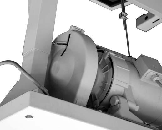
25 8. Put the V-belt on and tighten for the FIR clutch motor Take off the protective cover. Remove handwheel 1. Remove the protective belt cover 4 on the sewing drive. Put on the V-belt and mount the protective cover. Fasten the belt pulley (in the drive package) to the shaft of the sewing drive. Put the V-belt 6 on the belt pulley 7 located on the machine head. Guide the V-belt 6 downwards through the cut-out in the table plate. Loosen the screw 3 on the base of the sewing drive. Put the V-belt 6 on the sewing drive s belt pulley. Mount the protective belt cover 2 on the machine head. Mount the handwheel 1. Tightening the V-belt Loosen the screw 3 on the base of the sewing drive. Tighten the V-belt by swivelling out the sewing drive. When the belt has the correct tension, you should be able to press down with your finger in the middle of the belt 6 (without excessive force) so that the belt moves about 10 mm down. Tighten screw 3. GB Assembling the protective belt cover on the sewing drive Adjust the belt run-off safeguard 5 (an adjustable angle or cam, depending on the drive type) on the belt cover 4 as follows: When the machine head is tilted back, the V-belt 6 must remain on the belt pulley. Also refer to the operating instructions from the motor manufacturer. Screw on the lid of the belt cover 4. 21


26 9. Mounting the Knee Lever The sewing feet can be lifted mechanically by the knee lever 1. Attach the knee lever 1. Position the knee lever from below so that the nose 2 points to the front. Tighten screw 3 into the machine base. 5 4 Aligning the knee lever Loosen screws 4 and 5. Align the knee lever. Re-tighten screws 4 and 5. 6 Aligning the knee cushion Loosen screw 6. Align the knee cushion 7. Re-tighten screw
 so that it can be easily shifted. Put on the V-belt 5.")


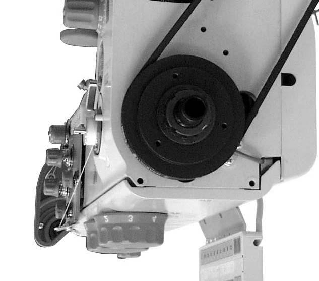
27 10. Mounting the Direct Drive 10.1 Mounting the motor and putting on the V-belt Unscrew the handwheel 1. Screw motor 3 onto the head using two screws 4 (M6 x 16) so that it can be easily shifted. Put on the V-belt 5. Tighten the V-belt. Press the motor 3 downwards and tighten both screws 4. When the belt has the correct tension, you should be able to press down with your finger in the middle of the belt 6 (without excessive force) so that the belt moves about 10 mm down. GB 10.2 Connecting the Hall sensor Caution: Risk of injury! Turnthemainswitchoff. Connect the Hall sensor only with the sewing machine turned off. 7 6 Screw off the arm cover 7 and valve cap 6. 23
.")

. 11 12 2 13 Take out the section 12 from the protective belt cover 2.")
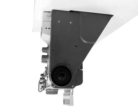
28 Fasten the Hall sensor 15 to the holder 8 using two screws 14 (M4 x 5). Fasten the holder 8 with the Hall sensor 15 to the arm 8 using two screws 10 (M4 x 8). Guide the cable 11 through the clips 9. Route cable 11 in the arm and then to the control cabinet under the table plate. Screw on the arm cover 7. Connect the 9-pole Sub-D plug from the Hall sensor into B18" socket on the EFKA DA321G controller (IPG / HSM / LSM) Take out the section 12 from the protective belt cover 2. Use a sharp knife to cut through the sections shown by 13. Mount the protective belt cover on the machine head. Mount the handwheel 1. 24


29 10.3 Mounting the operating panel Screw on operating panel 1 along with the thread guide 2. Take off the valve cap 3. Route the panel s connection cable 5: Route the cable in the arm and then downwards through the opening in the table plate. Plug in the cable plug into the B776 socket on the drive controller. Put the valve cap 3 back on. GB 25


30 10.4 Mounting the sewing light (optional equipment) CAUTION! The power supply to the sewing light is not disconnected when the main switch is turned off. Remember to pull out the mains plug before making this connection The sewing light 1 will be mounted on the arm cover 2. Screw off the arm cover 2. Use a 4.5-mm Ø bit to drill the fastening holes 3. Screw the retainer piece 5 using screw 4. Put the sticker with the safety notice on the front of the main switch 7. Put the sewing light onto the retainer piece 5. Unscrew the valve cap 6. Route the sewing light s supply cable into the cut-out on the machine arm. Guide the the connection cable downwards through the opening in thetableplate. Fasten the sewing light transformer under the table plate using particle-board screws. Plug in the connector for the transformer s power supply. Put on the cover 2 and valve cap

 cable 1 is included in the machine s accessory pack.")
. Then route the cable through the cable duct to the motor foot.")
31 11. Electrical Connections 11.1 General Caution! All work on the electrical equipment of the sewing machine may only be carried out by qualified electricians or other appropriately trained persons. The power cord must always be disconnected while working on the electrical equipment! 11.2 Earthing Machine head GB The earth (grounding) cable 1 is included in the machine s accessory pack. The earth cable 1 conducts static charges from the machine head via the motor foot to the earth. Connect the earth cable 1 to the tab connector 2 (connector is already screwed on to the machine head). Then route the cable through the cable duct to the motor foot. Screw the earth cable 1 to the motor foot or control box using screw 3. The earth cable 1 should also be fastened under the table plate with nail clips. Caution! Make sure that the earth cable 1 does not come into contact with the V-belt. Note: For sewing machines with a sewing drive integrated into the machine head, there is no need to establish equipotential bonding since this is implemented with the attached motor. 27

32 Knee switch Fasten the large eyelet on the earth cable 1 to the knee switch using screw 2. Screw the earth cable 2 to the control box using screw 3. 28
33 11.3 Checking the mains supply voltage Caution! The nominal voltage given on the sewing drive s identification plate must correspond to the mains voltage where it is to be operated Connecting the clutch motor (FIR) to the mains voltage Caution! A pluggable connection must be used to connect the sewing machine to the mains supply voltage! The clutch motor should be connected to three-phase current: 3 x V 50/60Hz or 3 x V 50/60Hz. (Refer to the table in Chapter 5.2.) The connection should be established according to the connection diagrams A or D. Route the connection cable from the main switch through the cable duct to the sewing drive. Then connect the cable to the sewing drive. Refer to the connection diagram A/ D (in the connections kit) or to the circuit diagram on the clutch motor. Route the voltage supply cable from the main switch through the cable duct to the rear. Then fasten with the strain relief mechanism. GB 29
34 Rotational direction of the clutch motor Caution! Make sure to check the rotational direction of the sewing drive before initial commissioning of the sewing machine! Operating the sewing machine with the incorrect rotational direction can damage the machine Checking the rotational direction The rotational direction of the clutch motor (a three-phase motor) is dependent on the three-phase mains connection and the method of assembly used. In order to check the rotation before use, do the following: Connect the clutch motor. Establish equipotential bonding. Connect the sewing drive to the mains supply. (Refer to Chapters 11.2 and 11.4.) Turnthemainswitchon. Press the pedal (or the motor s clutch lever) until the belt pulley starts to turn. The handwheel must rotate in the direction of the arrow Changing the rotational direction If the sewing drive is turning in the false direction, then you must swap two phases at the mains terminals for the sewing drive. Take the following steps: Turn off the main switch and unplug the mains plug! Swap the positions of two of the three phase wires at the sewing drive s mains connection. Plug in the mains plug and switch on the main switch. Re-check the rotational direction (Refer to Chapter ). 30

35 Connecting the sewing light transformer (optional equipment) 2 1 CAUTION! The transformer for the sewing light is connected directly to the mains power supply and is live even when the main switch has been turned off. Always pull out the mains plug before starting any work on the transformer (for example, when changing the fuse). GB Pull out the mains plug to the sewing machine! Route the mains cable 1 for the transformer 2 through the cable duct 3 to the main switch. Make the connection on the mains side of the main switch (or motor protective switch). Refer to connection diagram B. Put the sticker with the safety notice on the front of the main switch. A neutral conductor must be used if you are connecting the transformer to a three-phase 3 x 380V V power supply. 31
36 11.5 Connecting the DC positioning drive to the mains voltage Caution! A pluggable connection must be used to connect the sewing machine to the mains supply voltage! The DC positioning drive is run with single-phase AC current of V 50/60Hz. The connection should be made according to the connection diagram A or R. When connecting to a three-phase supply of 3x380V, 3x400V or 3x415V, the sewing drive should be connected to one phase and to a neutral conductor. When connecting to a three-phase supply of 3x200V, 3x220V, 3x230V or 3x240V, the sewing drive should be connected to two of the phases. If multiple DC positioning drives need to be connected to the same three-phase supply, you should distribute the connections amongst all of the phases equally so that no single phase is overloaded Connecting the sewing machine head The cable numbered is plugged into the head distributor This cable is then routed downwards inside the head. The 37-pole plug on the cable should be connected and screwed in to socket A on the sewing drive. 32
37 Connecting the DA321G control unit 3 4 KN Plug the cable from the setpoint director device (pedal) into the B80 socket on the control unit. Plug the motor sensor cable 1 into the B2 socket on the controller. Plug the motor cable 2 into the B41 socket on the controller. Plug the cable leading to the sewing machine into the A socket on the controller. Route all cables through the cable duct. Plug the cable from the operating panel (if available) into the B776 socket. Plug the cable 3 from the knee switch into the KN19 socket on the front side. Use the clips 4 to fasten down the cable 3 (only with ). GB 33
38 Checking the rotational direction of the DC positioning drive CAUTION! Make sure to check the rotational direction of the sewing drive before commissioning the sewing machine. Operating the sewing machine with the incorrect rotational direction can damage the machine. The arrow on the belt cover indicates the machine s proper direction of rotation. A reset value in the control unit parameter defines the rotational direction of the handwheel as counter-clockwise. This specifies the rotational direction of the DC positioning motor. However, the rotational direction must be verified before the initial commissioning of the machine. Take the following steps: Set the sewing foot in the high position. The plugs from the set-value initiator, motor, motor sensor and operating panel (if present) must be connected. The 37-pole plug from the sewing machine head should not be plugged in. Turnthemainswitchon. The operating panel displays Inf A5" or A5". This means that a valid Auto-select resistant has not been detected. The maximum rotational speed will therefore be limited. Press down gently forwards on the pedal. The drive starts to turn. Check the rotational direction. If the rotational direction of the drive is incorrect, then you must set the technical-level parameter 161" to a value of 1. (Refer to the instructions from the drive manufacturer.) Turnthemainswitchoff. Reconnect the 37-pole plug from the sewing machine head 34
39 Checking the positioning The needle position should already be properly set upon arrival of the sewing machine. However, the needle position should be checked before starting up the machine. Prerequisite The sewing foot should be set in the high position. (Refer to the operating instructions.) The machine should be set to stopover position 1 (with the needle down). Position 1 Turnthemainswitchon. Press forward on the pedal briefly and then return to starting position. The needle is in position 1. Check the position of the needle. Position 2 (only with switched-off reverse rotation (parameter 182 set to 0) Press the pedal first forward and then completely back. The needle is in position 2 (thread lever is at top dead centre). Check the position of the thread lever. GB If one or both needle positions are incorrect, then you must correct the positioning. (Refer to the operating instructions.) Machine-specific parameters General The programming and setting of parameters are used to specify the functions of the sewing drive controller. Auto-select The controller detects which sewing machine class is connected by measuring the auto-select resistance from the machine. Auto-select is used to select the control functions and the pre-set values of the parameters. CAUTION! If the controller detects an invalid or absent auto-select resistance, then the sewing drive will only operated with emergency-run functions. This serves to protect the machine from damage. The correct machine class can be set using parameter F-290, in accordance with the parameter data sheet PB. 35
40 In order to ensure that the machine is properly positioned and that all functions are correct, the following parameters must be verified or set correctly: Parameter F-111: set to 3000 rpm or less. Parameter F-270: set to 6 (selection of positioning sensor) Parameter F-272: calculate with the following formula: Diameter of the motor belt pulley Diameter of the machine belt pulley x Master reset A master reset will reset all parameter values to their default settings. After a master reset, the machine-specific parameters must be correctly specified again. 36


41 Connecting the sewing light on the DA321G control unit Loosen the four screws on the front plate of the control unit. Take off the front plate. Push the cable from the rear through the cable duct 1 in the controller. Take off the black rubber guide track 2. Use a screwdriver to punch though the circular opening in the guide track. Guide the cable for the sewing light transformer through this new opening. Replace the guide track. Use a thin screwdriver to press on the terminal openings 4 and 3. This opens up the terminals 5 and 6. Connect the blue cable to terminal 6 and the brown cable to terminal 5. Reattach the front plate using the four screws. GB 37
 for stands with compressed-air maintenance units.")
42 12. Pneumatic Connections CAUTION! The pneumatic equipment will only function smoothly when the system s supply pressure in between 8 and 10 bar. The operating pressure of the sewing machine is 6 bar. Pneumatic connection package You can order a pneumatic connection package (order number ) for stands with compressed-air maintenance units. The package contains the following components: Connection hose, 5 m long, (Ø =9 mm) Hose connector gland and hose fitting Coupling socket and coupling plug 1 Connecting the compressed-air maintenance unit Fasten the compressed-air maintenance unit 1 to the stand brace using the angle bracket, screws and strap. Connect the maintenance unit to the compressed air supply using a connection hose 5 (Ø =9 mm) and a R1/4" hose coupling. 38
 with the distributor plate 7 located on the machine head. Screw the cap 6 back on.")

43 Connecting the maintenance unit to the sewing machine head Unscrew the cap 6. Connect hose 3 (in accessory pack) with the distributor plate 7 located on the machine head. Screw the cap 6 back on. Setting the operating pressure The operating pressure is 6 bar. It can be read using the pressure gauge 4. In order to set the pressure, pull up on the turning handle 2 and turn. In order to raise the pressure, turn the handle 2 clockwise. In order to decrease the pressure, turn the handle 2 counter-clockwise. GB 39

44 13. Lubrication Caution: Risk of injury! Oil can cause skin rashes. Avoid prolonged skin contact. If oil or grease contacts your skin, wash yourself thoroughly. CAUTION! The handling and disposal of mineral oils is subject to legal constraints. Deliver used oil to an authorized reception point. Protect your environment. Take care not to spill any oil. Oil the sewing machine exclusively with the lubricating oil DA-10 or equivalent oil with the following specification: Viscosity at 40 C : 10 mm²/s Flash point: 150 C DA-10 can be purchased at sales branches of DÜRKOPP ADLER AG, under the following part numbers: 250-ml container: litre container: litre container: litre container: Lubricating the machine head (for the initial filling) Note All wicks and felt in the head are saturated with oil before being delivered. This oil is carried back to the storage reservoir 1. Do not overfill the reservoir. Fill oil into the reservoir 1 using the hole 2. Fill until you reach the max mark 3. 40
45 14. Sewing test After setup is complete, a sewing test must be carried out. Plug in the power supply plug. Caution: Risk of injury! Turnthemainswitchoff. The needle thread and shuttle thread must be threaded only when the machine is turned off. Thread in the winder thread (refer to the operating instructions, Chapter 6.11). Turnthemainswitchon. Set the sewing feet in their raised positions (refer to operating instructions, Chapter 6.11). Fill up the bobbin winder at low speed. Turnthemainswitchoff. Thread in the needle and bobbin thread (refer to operating instructions, Chapters 6.1 and 6.6). Select the material to be processed. Carry out the sewing test initially with a slow speed and then continually accelerating. Check that the seams satisfy requirements. If your requirements are not met, change the thread tension (refer to the operating instructions, Chapters 6.2, 6.4 and 6.7). If necessary, the settings detailed in the Service Guide should also be checked and corrected. GB 41
46 For your notes: 42
CNC Knopfannähautomat CNC Automat for Button Sewing
 531 CNC Knopfannähautomat CNC Automat for Button Sewing Bedienanleitung / Operating Instructions Aufstellanleitung / Installation Instructions Serviceanleitung / Service Instructions 1 3 Postfach 17 03
Speedpocket. Sewing unit for runstitching of rectangular piped pockets. Operating Instructions. Installation Instructions. Service Instructions
 745-34 Speedpocket Sewing unit for runstitching of rectangular piped pockets Operating Instructions Installation Instructions Service Instructions Instructions for programming DAC 1 3 4 Postfach 17 03
Spezialnähmaschine. Betriebsanleitung. Instruction manual
 669 Spezialnähmaschine Betriebsanleitung Instruction manual D GB Postfach 17 03 51, D-33703 Bielefeld Potsdamer Straße 190, D-33719 Bielefeld Telefon +49 (0) 521 / 9 25-00 Telefax +49 (0) 521 / 9 25 24
Part 2: Installation Instructions cl
 Contents Page: Part 2: Installation Instructions cl. 381-382 1. Delivery scope............................... 3 2. General and Transportation safety precautions........... 3 3. Stand installation 3.1 Installing
Spezialnähmaschine. Betriebsanleitung. Instruction manual
 171 173 Spezialnähmaschine Betriebsanleitung Instruction manual D GB Postfach 17 03 51, D-33703 Bielefeld Potsdamer Straße 190, D-33719 Bielefeld Telefon +49 (0) 521 / 9 25-00 Telefax +49 (0) 521 / 9 25
Spezialnähmaschine. Betriebsanleitung. Instruction manual
 869 Spezialnähmaschine Betriebsanleitung Instruction manual D GB Postfach 17 03 51, D-33703 Bielefeld Potsdamer Straße 190, D-33719 Bielefeld Telefon +49 (0) 521 / 9 25-00 Telefax +49 (0) 521 / 9 25 24
Instructions, complete. Operating Instructions. Installation Instructions. Service Instructions
 506-3 Instructions, complete Operating Instructions Installation Instructions Service Instructions 2 3 Postfach 7 03 5, D-33703 Bielefeld Potsdamer Straße 90, D-3379 Bielefeld Telefon +49 (0) 52 / 9 25-00
Spezialnähmaschine. Betriebsanleitung. Instruction manual
 887 Spezialnähmaschine Betriebsanleitung Instruction manual Postfach 17 03 51, D-33703 Bielefeld Potsdamer Straße 190, D-33719 Bielefeld Telefon +49 (0) 521 / 9 25-00 Telefax +49 (0) 521 / 9 25 24 35 www.duerkopp-adler.com
Spe ci al se wing ma chi ne
 267 Spe ci al se wing ma chi ne CN In struc tions for ope ra ting GB Post fach 17 03 51, D-33703 Bie le feld Pots da mer Stra ße 190, D-33719 Bie le feld Te le fon + 49 (0) 5 21 / 9 25-00 Te le fax + 49
Spezialnähmaschine. Betriebsanleitung. Instruction manual
 838 Spezialnähmaschine Betriebsanleitung Instruction manual DE EN Postfach 7 03 5, D-33703 Bielefeld Potsdamer Straße 90, D-3379 Bielefeld Telefon +49 (0) 52 / 9 25-00 Telefax +49 (0) 52 / 9 25 24 35 www.duerkopp-adler.com
Spezialnähmaschine. Betriebsanleitung. Instruction manual
 887 Spezialnähmaschine Betriebsanleitung Instruction manual DE EN Postfach 17 03 51, D-33703 Bielefeld Potsdamer Straße 190, D-33719 Bielefeld Telefon +49 (0) 521 / 9 25-00 Telefax +49 (0) 521 / 9 25 24
IMPORTANT SAFETY INSTRUCTIONS
 CONTENTS 1.SPECIFICATIONS... 1 2.INSTALLATION... 1 3.INSTALLATION OF THE SYNCHRONIZER... 2 4.ASSEMBLY OF HAND WHEEL... 2 5.INSTALLATION OF HAND WHEEL... 2 6.INSTALLING THE BELT COVER... 3 7.ADJUSTING THE
Special Sewing Machine
 884 Special Sewing Machine Instruction manual Postfach 17 03 51, D-33703 Bielefeld Potsdamer Straße 190, D-33719 Bielefeld Telefon +49 (0) 521 / 9 25-00 Telefax +49 (0) 521 / 9 25 24 35 www.duerkopp-adler.com
M-TYPE CLASSIC M-TYPE PREMIUM. Additional Instructions. Electropneumatic needle cooling
 M-TYPE CLASSIC M-TYPE PREMIUM Additional Instructions Electropneumatic needle cooling IMPORTANT READ CAREFULLY BEFORE USE KEEP FOR FUTURE REFERENCE All rights reserved. Property of Dürkopp Adler AG and
Please read this manual before using the machine. Please keep this manual within easy reach for quick reference.
 DA-927A DA-928A INSTRUCTION MANUAL Please read this manual before using the machine. Please keep this manual within easy reach for quick reference. TWIN NEEDLE / THREE NEEDLE FEED OFF THE ARM DOUBLE CHAIN
DA-9270 TWIN NEEDLE (THREE NEEDLE) FEED OFF THE ARM DOUBLE CHAIN STITCHER. English
 FEED OFF THE ARM DOUBLE CHAIN STITCHER. English") TWIN NEEDLE (THREE NEEDLE) FEED OFF THE ARM DOUBLE CHAIN STITCHER English Thank you very much for buying a BROTHER sewing machine. Before using your new machine, please read the safety instructions below
TWIN NEEDLE (THREE NEEDLE) FEED OFF THE ARM DOUBLE CHAIN STITCHER English Thank you very much for buying a BROTHER sewing machine. Before using your new machine, please read the safety instructions below
Please read this manual before using the machine. Please keep this manual within easy reach for quick reference.
 INSTRUCTION MANUAL Please read this manual before using the machine. Please keep this manual within easy reach for quick reference. HIGH SPEED SINGLE NEEDLE STRAIGHT LOCK STITCHER Thank you very much for
Speedpocket. Sewing unit for runstitching of rectangular piped pockets. Operating Instructions. Installation Instructions. Service Instructions
 745-34 Speedpocket Sewing unit for runstitching of rectangular piped pockets Operating Instructions Installation Instructions Service Instructions Instructions for programming DAC 2 3 4 Postfach 7 03 5,
888 Operating Instructions
 888 Operating Instructions All rights reserved. Property of Dürkopp Adler AG and copyrighted. Reproduction or publication of the content in any manner, even in extracts, without prior written permission
Please read this manual before using the machine. Please keep this manual within easy reach for quick reference.
 INSTRUCTION MANUAL Please read this manual before using the machine. Please keep this manual within easy reach for quick reference. SINGLE NEEDLE DIRECT DRIVE STRAIGHT LOCK STITCHER WITH THREAD TRIMMER
Spezialnähmaschine. Bedienanleitung. Operating Instructions. Instructions de maniement
 367 Spezialnähmaschine Bedienanleitung Operating Instructions Instructions de maniement D GB F Postfach 17 03 51, D-33703 Bielefeld Potsdamer Straße 190, D-33719 Bielefeld Telefon +49 (0) 5 21/ 9 25-00
Industrial Sewing Machine TECHNICAL MANUAL SEWING MACHINE HEAD. Electronic Pattern Sewing Machine. Model PLK-G1010 A180E593P03
 Industrial Sewing Machine TECHNICAL MANUAL SEWING MACHINE HEAD Electronic Pattern Sewing Machine Model PLK-G1010 A180E593P03 FOR SAFE USE Before the installation, operation, and inspection for this product,
PREMIER SERIES BY P1255RBL-18 P2339RBL-18
 PREMIER SERIES BY P1255RBL-18 P2339RBL-18 P2339RBL-18 P1255RBL-18 P2339RBL- P1255RB- P2339RBL- 1. P2339RBL 18 Machine casting components Line Part Number Description Qt. Notes 1 300 1002 Machine
ENGINEER S MANUAL No.01
 1-NEEDLE, UNISON FEED, LOCKSTITCH MACHINE (AUTOMATIC LUBRICATION) LU-1510 1-NEEDLE, UNISON FEED, LOCKSTITCH MACHINE WITH AUTOMATIC THREAD TRIMMER (AUTOMATIC LUBRICATION) LU-1510-7 1-NEEDLE, UNISON FEED,
EHA Hoffmann International GmbH
 EHA Hoffmann International GmbH User manual EHA-TRANSPRINT HP 2020 Machine-No.: Year: EHA Hoffmann International GmbH Michelsbergstraße 24 D-57080 Siegen/Germany Telephone: +49 271 39 32-0 Telefax: +49
USER S MANUAL. SS-7350 Series. Small cylinder bed interlock sewing machine
 R USERS MANUAL SS-7350 Series Small cylinder bed interlock sewing machine R Best Quality Best Price Best Service 1. Thank you for purchasing our product. Based on the rich expertise and experience accumulated
Industrial Sewing Machine TECHNICAL MANUAL SEWING MACHINE HEAD. Electronic Pattern Sewing Machine. Model PLK-G2516 A180E621P01
 Industrial Sewing Machine TECHNICAL MANUAL SEWING MACHINE HEAD Electronic Pattern Sewing Machine Model PLK-G2516 A180E621P01 FOR SAFE USE Before the installation, operation, and inspection for this product,
INSTRUCTION MANUAL. This instruction manual applies to machines from the following serial numbers onwards: #
 245 246 INSTRUCTION MANUAL This instruction manual applies to machines from the following serial numbers onwards: # 6 500 24 296-2-9 99/002 Betriebsanleitung engl. 05.2 This Instruction Manual is valid
RH-981A ENGLISH ELECTRONIC EYELET BUTTON HOLER
 ENGLISH ELECTRONIC EYELET BUTTON HOLER Thank you very much for buying a BROTHER sewing machine. Before using your new machine, please read the safety instructions below and the explanations given in the
Part 1: class 69 operating instructions
 Contents Page: Preface and general safety instructions Part 1: class 69 operating instructions 1. Product description............................ 5 2. Designated use.............................. 5 3.
Industrial Sewing Machine TECHICAL MANUAL SEWING MACHINE HEAD. Electronic Pattern Sewing Machine. Model PLK-G1010 A180E593P02
 Industrial Sewing Machine TECHICAL MANUAL SEWING MACHINE HEAD Electronic Pattern Sewing Machine Model PLK-G1010 A180E593P02 FOR SAFE USE Before the installation, operation, and inspection for this product,
CONTENTS 1. SPECIFICATIONS SET-UP FOR THE OPERATOR MAINTENANCE... 34
 ENGLISH ii CONTENTS. SPECIFICATIONS... 2. SET-UP.... Installing the motor unit... 2. Installing the control box... 3. Installing the belt... 2 4. Adjusting the pulley cover... 2 5. Installation and adjustment
Part 3: Service manual, class
 Contents Page: Part : Service manual, class 7-75. General.................................................. Gauges................................................. 4. Description and adjustment of the
AK-154 INSTRUCTION MANUAL
 AK-154 INSTRUCTION MANUAL 1 CONTENTS 1. FEATURES... 1 2. INSTALLATION... 2 3. HOW TO SELECT THE FUNCTION OF AUTO-LIFTER... 5 4. OTHERS (Advanced edition)... 6 4-1. Function for reducing the presser foot
Industrial Sewing Machine TECHNICAL MANUAL MECHANICAL VERSION. Electronic Pattern Sewing Machine. Model PLK-E2010R A180E530P01
 Industrial Sewing Machine TECHNICAL MANUAL MECHANICAL VERSION Electronic Pattern Sewing Machine Model PLK-E2010R A180E530P01 FOR YOUR SAFETY! If you are operating the sewing machine for first time, please
MSK-8900M Industrial Sewing Machine. Instruction Manual
 MSK-8900M Industrial Sewing Machine Instruction Manual CONTENTS Operation instruction. Brief introduction. Main specifications. Main parts name 4. The method of installation 5 5. Pareparation before sewing
User s Manual: WERI Mini Applicator
 User s Manual: User s Manual Page 1 of 15 Table of Content 1 Document revision history... 2 2 Important warnings... 3 3 Symbols... 4 4 Identification... 5 5 Technical data... 5 6 Installation (trained
Technical Data. Name: ERIKA Automat fully automatic machine to divide and to round dough pieces of the same size
 AUTOMAT MANUAL 1 Technical Data Name: ERIKA Automat fully automatic machine to divide and to round dough pieces of the same size Type Divisions Dough Portions (in ounces) Plate Nos. 3 30 1.0 3.5 #35 4/40A
Please read this manual before using the machine. Please keep this manual within easy reach for quick reference.
 INSTRUCTION MANUAL Please read this manual before using the machine. Please keep this manual within easy reach for quick reference. SINGLE NEEDLE DIRECT DRIVE LOCK STITCHER WITH ELECTRONIC FEEDING SYSTEM
PLC-1700 Series PLC-1710, , 1760, , 1760L
 Post-bed, Unison-feed, Lockstitch Machine PLC-1700 Series PLC-1710, 1710-7, 1760, 1760-7, 1760L ENGINEER S MANUAL 40040656 No.E372-00 Introduction This Engineer s Manual is for technical service engineers.
Instruction Manual and Parts List. Ultra High Speed Overedge and Safety Stitch Machine
 Instruction Manual and Parts List Ultra High Speed Overedge and Safety Stitch Machine 32D 3M-04 3M-04 / KS 32M-05 34M-04 24M-24 24M-24 / KS 244M-24 25M-35 25M-35 / KH 25M-55 25M-55 / KH 25M-56 25H-56 /
Please read this manual before using the machine. Please keep this manual within easy reach for quick reference.
 INSTRUCTION MANUAL Please read this manual before using the machine. Please keep this manual within easy reach for quick reference. SINGLE NEEDLE DIRECT DRIVE LOCK STITCHER WITH ELECTRONIC FEEDING SYSTEM
INSTRUCTION MANUAL. This instruction manual applies to machines from the following serial numbers onwards: and software version 0435/002.
 45 46 INSTRUCTION MANUAL This instruction manual applies to machines from the following serial numbers onwards: 7 6 454 and software version 0435/00. 96--9 30/00 Instruction Manual engl. 0.5 This instruction
SC-922 InStruCtIon Manual
 SC-922 Instruction Manual CONTENTS I. SPECIFICATIONS... 1 II. SET-UP... 1 1. Installing to the table...1 2. Installing the motor unit...2 3. Installing the control box...2 4. Installing the belt...3 5.
DDL-900B INSTRUCTION MANUAL
 DDL-900B INSTRUCTION MANUAL CONTENTS I. SPECIFICATIONS... 1 II. SET-UP... 3 1. Installation...3 2. Installing the pedal sensor...4 3. Installing the power switch (for CE)...4 4. Connecting the connector...5
Model PLK-G5050 PLK-G10050
 Industrial Sewing Machine TECHNICAL MANUAL SEWING MACHINE HEAD Electronic Pattern Sewing Machine Model PLK-G5050 PLK-G10050 A180E686P01 FOR SAFE USE Before the installation, operation, and inspection for
PARTS LIST. Specification code: (JAI 45231) (JA) (JCA) (JUK) (JHBV)
 (JA) (JCA) (JUK) (JHBV)") PARTS LIST Specification code: 832-711-004 (JAI 45231) 832-712-005 (JA) 832-713-006 (JCA) 832-714-007 (JUK) 832-716-009 (JHBV) 14 13 1 2 6 10 12 9 11 8 7 3 5 4 7 1 KEY PART NO. NO. NAME 1 832649011 Needle
PARTS LIST Specification code: 832-711-004 (JAI 45231) 832-712-005 (JA) 832-713-006 (JCA) 832-714-007 (JUK) 832-716-009 (JHBV) 14 13 1 2 6 10 12 9 11 8 7 3 5 4 7 1 KEY PART NO. NO. NAME 1 832649011 Needle
52 CEILING FAN READ AND SAVE THESE INSTRUCTIONS FAN RATING AC 120V.
 Irene 52 CEILING FAN READ AND SAVE THESE INSTRUCTIONS FAN RATING AC 120V. 60Hz TABLE OF CONTENTS Tools and Materials Required... 1 Package Contents... 1 Safety Rules... 2 Mounting Options... 3 Hanging
DDL-900A INSTRUCTION MANUAL
 DDL-900A INSTRUCTION MANUAL COVERI CONTENTS I. SPECIFICATIONS... 1 II. SET-UP... 3 1. Installation...3 2. Installing the pedal sensor...4 3. Installing the power switch (for CE)...4 4. Connecting the connector...5
MITSUBISHI. Industrial Sewing Machine. Model PLK-E1010 TECHNICAL MANUAL MECHANICAL VERSION. Electronic Pattern Sewing Machine A180E494P01
 MITSUBISHI Industrial Sewing Machine TECHNICAL MANUAL MECHANICAL VERSION Electronic Pattern Sewing Machine Model PLK-E00 A80E9P0 FOR YOUR SAFETY! If you operate the sewing machine first time, please make
OPERATING MANUAL Gfp 255C Please read this manual carefully before operating!
 OPERATING MANUAL Gfp 255C Please read this manual carefully before operating! Unpacking, assembly, and operating videos are available at www.gfpsmoothstart.com 1 Table of Contents Gfp 255C March 2015 Contents
OPERATING & SERVICE PARTS MANUAL HDS-215 COMBINATION SHRINK SYSTEM
 OPERATING & SERVICE PARTS MANUAL HDS-215 COMBINATION SHRINK SYSTEM FOR HOT KNIFE AND IMPULSE MACHINES READ ALL INSTRUCTIONS CAREFULLY BEFORE OPERATING EQUIPMENT TABLE OF CONTENTS Electrical Requirements
PLC-2700 Series INSTRUCTION MANUAL
 PLC-2700 Series INSTRUCTION MNUL CONTENTS 1. SPECIFICTIONS... 1 2. INSTLLTION... 4 2-1. Installation of the sewing machine...4 2-2. djusting the belt tension (PLC-2710, 2760, 2760L, 2765)...6 2-3. Pneumatic
DDL-900BB INSTRUCTION MANUAL
 DDL-900BB INSTRUCTION MANUAL CONTENTS I. SPECIFICATIONS... 1 II. SET-UP... 3 1. Installation...3 2. Installing the pedal sensor...4 3. Installing the power switch (for CE)...5 4. Connecting the connector...6
Dryer. User manual DV22K6800** DV22K A-00_EN (US)_ indd :15:41
_ indd :15:41") Dryer User manual DV22K6800** DV22K6800-03650A-00_EN (US)_151211.indd 1 2015-12-11 7:15:41 Before installation Read through the following instructions before installing the dryer, and keep this manual
Dryer User manual DV22K6800** DV22K6800-03650A-00_EN (US)_151211.indd 1 2015-12-11 7:15:41 Before installation Read through the following instructions before installing the dryer, and keep this manual
CEILING FAN OWNER'S MANUAL
 Style that revolves around you. CEILING FAN OWNER'S MANUAL Vail with DC motor 10/15 WARNING: Read and follow these instructions carefully and be mindful of all warnings shown throughout. GENERAL INSTALLATION
DDL-8700B-7 INSTRUCTION MANUAL
 DDL-8700B-7 INSTRUCTION MANUAL I CONTENTS I. SPECIFICATIONS... 1 II. SET-UP... 3 1. Installation...3 2. Installing the pedal sensor...4 3. Connecting the connector...4 4. How to install the power plug...5
OPERATING MANUAL Gfp 800 Series
 OPERATING MANUAL Gfp 800 Series Please read this manual carefully before operating! 1 Contents Table of Contents Page 1. Introduction 3 2. Important Safety Instructions.. 3 3. Installation Safeguards..
C-IV 60 CEILING FAN READ AND SAVE THESE INSTRUCTIONS. FAN RATING AC 120V. 60Hz
 C-IV 60 CEILING FAN READ AND SAVE THESE INSTRUCTIONS FAN RATING AC 120V. 60Hz Please do not use any electric or battery powered tools in the assembly and installation of this or any Matthews Fan Company
CEILING FAN OWNER'S MANUAL
 Style that revolves around you. CEILING FAN OWNER'S MANUAL Hover with DC motor 12/14 WARNING: Read and follow these instructions carefully and be mindful of all warnings shown throughout. GENERAL INSTALLATION
Fillmore Small Pendant Assembly and Installation Instructions
 CAUTION: Fillmore Small Pendant Assembly and Installation Instructions BEFORE INSTALLING FIXTURE, MAKE SURE THE POWER TO THE CIRCUIT IS TURNED OFF AT THE MAIN FUSE BOX / CIRCUIT BREAKER UTILITY BOX. Important
CEILING FAN OWNER'S MANUAL
 Style that revolves around you. CEILING FAN OWNER'S MANUAL VANTAGE with DC motor 12/14 WARNING: Read and follow these instructions carefully and be mindful of all warnings shown throughout. GENERAL INSTALLATION
1. SAFETY RULES WARNING WARNING. 8. Avoid placing objects in the path of the blades.
 1 1. SAFETY RULES 1. To reduce the risk of electric shock, insure electricity has been turned off at the circuit breaker or fuse box before beginning. 2. All wiring must be in accordance with the National
SuperKlean Washdown Products
 DURAREEL DR8 & DR8S INSTALLATION AND MAINTENANCE INSTRUCTIONS **DO NOT THROW AWAY AFTER INSTALLATION** **SAVE AND DISPLAY PROMINENTLY WHERE THIS EQUIPMENT IS USED** GENERAL WARNINGS High pressure and hot
DOUBLE DISHDRAWER TM DISHWASHER
 DOUBLE DISHDRAWER TM DISHWASHER DD60DA & DD60DC models INSTALLATION GUIDE NZ AU GB IE 591151C 08.17 WARNING! Electrical shock hazard Before installing the dishwasher, remove the house fuse or open the
52Xi. Industrial sewing machine. Instruction manual. Betriebsanleitung
 52Xi Industrial sewing machine Instruction manual Betriebsanleitung GB D Postfach 17 03 51, D-33703 Bielefeld Potsdamer Straße 190, D-33719 Bielefeld Telefon +49 (0) 521 / 9 25-00 Telefax +49 (0) 521 /
52 DorsetTM. Instruction Manual. Basic Function Wall Control System Included. A Kichler Decor ceiling fan
 Basic Function Wall Control System Included 52 DorsetTM II A Kichler Decor ceiling fan Kichler Lighting 7711 East Pleasant Valley Road P.O. Box 318010 Cleveland, Ohio 44131-8010 Customer Service 866.558.5706
60" Tulle PatioTM. Instruction Manual. A Kichler Select ceiling fan
 60" Tulle PatioTM A Kichler Select ceiling fan cul Certified for Wet Location Kichler Lighting 7711 East Pleasant Valley Road P.O. Box 318010 Cleveland, Ohio 44131-8010 Customer Service 866.558.5706 8:30
DOUBLE DISHDRAWER TM DISHWASHER
 DOUBLE DISHDRAWER TM DISHWASHER DD4DDFT & DD4DVT models INSTALLATION GUIDE US CA 5985 A 08.7 SAFETY AND WARNINGS! WARNING! Electrical Shock Hazard Before installing the dishwasher, remove the house fuse
EN Instruction manual
 EN Instruction manual For laboratory use. Flaming from any angle. DIN 30665, part 1 1 Overview 1 - Gas adjustment 2 - Status - LED 3 - Burner tube 4 - Flame orifice 5 - Connector for foot pedal 6 - Gas
SERVICE MANUAL. Freestanding cooker 500 and 600 / Range Gas- gas Electric CFSGSV14 CFSGWH14 CFSESV14 CFSEWH14
 Freestanding cooker 500 and 600 / Range 2013 Gas- gas Electric CFSGSV14 CFSGWH14 CFSESV14 CFSEWH14 SERVICE MANUAL 2 Door assembly Removing the door assembly 1. Lift the lock of the left and right door
TA-12. Tabbing System USER'S GUIDE
 TA-12 Tabbing System USER'S GUIDE SAFETY PRECAUTIONS THIS EQUIPMENT PRESENTS NO PROBLEM WHEN USED PROPERLY. HOWEVER, CERTAIN SAFETY RULES SHOULD BE OBSERVED WHEN OPERATING THE TA12 TABBER. BEFORE USING
52 Lacey LED. Instruction Manual. 6 Speed DC Wall Control System
 6 Speed DC Wall Control System 52 Lacey LED HIGH EFFICIENCY DC MOTOR Kichler Lighting 7711 East Pleasant Valley Road P.O. Box 318010 Cleveland, Ohio 44131-8010 Customer Service 866.558.5706 8:30 AM to
KE-430HX KE-430HS BE-438HX
 KE-430HX KE-430HS BE-438HX INSTRUCTION MANUAL Please read this manual before using the machine. Please keep this manual within easy reach for quick reference. ELECTRONIC DIRECT DRIVE LOCKSTITCH BAR TACKER
Service Instructions
 BASIC EXCELLENT PERFECT U Universal ovens I Incubators S Sterilisers Service Instructions Mo Tu We Th Fr Sa Su t3 on off h t2 t1 t4 loop 4 3 2 1 STERI DEFRO C MIN MAX C IN 1 IN 2 OUT IN 1 IN 2 OUT % rh
Installation Instructions 30 French Door Built-in Wall Ovens
 Installation Instructions 30 French Door Built-in Wall Ovens Questions? Call 1.800.GE.CARES (1.800.432.2737) or visit www.geappliances.com In Canada, call 1.800.561.3344 or visit www.geappliances.ca DESIGN
USER S MANUAL. KM-1060BL Series KM-1060BL KM-1060BL-7 KM-1062BL KM-1062BL-7
 USER S MANUAL KM-1060BL Series KM-1060BL KM-1060BL-7 KM-1062BL KM-1062BL-7 R Best Quality Best Price Best Service 1. Thank you for purchasing our product. Based on the rich expertise and experience accumulated
BARRACUDA 200ZW PORTABLE WALKING FOOT SEWING MACHINE INSTRUCTION MANUAL
 BARRACUDA 00ZW PORTABLE WALKING FOOT SEWING MACHINE INSTRUCTION MANUAL THE BARRACUDA 00ZW PORTABLE WALKING FOOT SEWING MACHINE INSTRUCTION MANUAL MATERIAL IS OWNED BY RELIABLE AND MAY NOT BE REPRODUCED
CEILING FAN OWNER S MANUAL
 CEILING FAN OWNER S MANUAL VERA CRUZ 5/04 GENERAL INSTALLATION & OPERATION INSTRUCTIONS IMPORTANT SAFEGUARDS: 1. To ensure the success of the installation, be sure to read the instructions and review the
MB-1800 Series INSTRUCTION MANUAL
 MB-800 Series INSTRUCTION MANUAL CONTENTS!. SPECIFICATIONS... @. NAME OF EACH COMPONENT.... Name of the main unit... #. INSTALLATION... $. PREPARATION OF THE SEWING MACHINE...7. Attaching the needle...
Installing a Fast Oven Upgrade Kit
 Agilent 6850 Series II Network GC System Accessory G3350B There are three Fast Oven upgrade kits: 120 V, 200 V, and 230 V. The following table indicates what each kit contains: Description Quantity 120
42 Kevlar. Instruction Manual. Kichler Lighting 7711 East Pleasant Valley Road P.O. Box Cleveland, Ohio
 42 Kevlar Kichler Lighting 7711 East Pleasant Valley Road P.O. Box 318010 Cleveland, Ohio 44131-8010 Customer Service 866.558.5706 8:30 AM to 5:00 PM EST, Monday - Friday Instruction Manual 1 1. SAFETY
Liste de pièces Lista de Piezas Parts List
 H74 Liste de pièces Lista de Piezas Parts List 104 23 73-96 17 Nov 2011 A 2 Singer H74 Pos Part No Description 1 416484501 THREAD TAKE UP LEVER COMPLETE 2 416147701 THREAD TAKE UP LEVER SUPPORTER 3 416116001
ValkyrieTM. Instruction Manual. Includes our new CoolTouch TM 6 Speed DC Control System Looks permanent, but goes wherever you go! U.S.
 ValkyrieTM A Kichler Décor ceiling fan Designed to coordinate with a popular Kichler Lighting collection. Includes our new CoolTouch TM 6 Speed DC Control System Looks permanent, but goes wherever you
51AKB / 51 AKC OWNER S MANUAL
 51AKB / 51 AKC OWNER S MANUAL This manual applies to the following models 51AKB 009 51AKB 012 51AKC 009 51AKC 012 Read this instruction manual thoroughly before using the air conditioner. Control panel
TECHNICAL INFORMATION B 890 and B 990 Rotary Irons (US Models)
") TECHNICAL INFORMATION B 890 and B 990 Rotary Irons (US Models) 2011 Miele USA Table of Contents A B C D 010 Warning and Safety Instructions... 5 1 General... 5 2 Touch Current Measurement... 6 3 Risk of
TECHNICAL INFORMATION B 890 and B 990 Rotary Irons (US Models) 2011 Miele USA Table of Contents A B C D 010 Warning and Safety Instructions... 5 1 General... 5 2 Touch Current Measurement... 6 3 Risk of
INSTALLATION AND MAINTENANCE OF THE "THOMPSON-BRITISH" AUTOMATIC PLATEN
 INSTALLATION AND MAINTENANCE OF THE "THOMPSON-BRITISH" AUTOMATIC PLATEN Installation and Maintenance of The "Thompson-British" Auto Platen Lifting Bolt. Motor. Direction of rotation. Oiling. The machine
Owner s Guide and Installation Manual
 Tribeca Owner s Guide and Installation Manual English Form# M6000-01 20120416 2012 Casablanca Fan Co. Welcome Your new Casablanca ceiling fan is an addition to your home or office that will provide comfort
Grain crusher Universal. Purpose: This machine is designed for the crushing of grain in agricultural operation.
 Grain crusher Universal. Purpose: This machine is designed for the crushing of grain in agricultural operation. Operating instructions and parts catalogue This grain crusher provides you with a machine
BL Series INSTRUCTIONS
 BL Series Models: EX5204/BL514 EX5204/BL515 EX5214/BL524 EX5214/BL525 EXT5214/BL524 EXT5214/BL525 EX5404/BL614 EX5404/BL615 EX5414/BL624 EX5414/BL625 EXT5214H/BL528 EXT5214H/BL529 Automatic Backlatcher
Sunburst. Instruction Manual. Includes our new Wall Control System. A Kichler Décor ceiling fan
 Includes our new Wall Control System Sunburst A Kichler Décor ceiling fan Kichler Lighting 7711 East Pleasant Valley Road P.O. Box 318010 Cleveland, Ohio 44131-8010 Customer Service 866.558.5706 8:30 AM
Dishwasher. Installation manual DW60M9990AP
 Dishwasher manual DW60M9990AP DW9000M_DD68-00197B-00_EN.indd 1 6/1/2017 4:34:14 PM Contents Contents 3 What s included 3 requirements 7 Dimensions and specifications 9 Step-by-step installation 11 2 English
LK3 B434E LK3-B434EX LK3 B434EX/SF Electronic Lockstitch Pattern Tacker Electronic Lockstitch Pattern Tacker with Stepping Foot
 LK3 B434E LK3-B434EX LK3 B434EX/SF Electronic Lockstitch Pattern Tacker Electronic Lockstitch Pattern Tacker with Stepping Foot Specifications Model LK3 B434E LK3 B434EX LK3 B434EX / SF Application Thin,
INSTRUCTION MANUAL. This instruction manual applies to machines from the following serial numbers onwards: and software version 0435/002.
 337 INSTRUCTION MANUAL This instruction manual applies to machines from the following serial numbers onwards: 7 6 535 and software version 0435/00. 96--9 37/00 Instruction Manual engl..5 This instruction
Cable Drum Machine. Operation Manual 40 SERIES. Cleans 2" to 4" lines up to 75' N O T F O R R O O T S
 Cable Drum Machine Operation Manual 40 SERIES Cleans 2" to 4" lines up to 75' Used For: Sinks, Showers & Floor Drains N O T F O R R O O T S WARNING - Read All Instructions, When Using Electric Tools, Basic
CEILING FAN OWNER'S MANUAL
 Style that revolves around you. CEILING FAN OWNER'S MANUAL QUATRO 10/09 WARNING: Read and follow these instructions carefully and be mindful of all warnings shown throughout. GENERAL INSTALLATION & OPERATION
LaceyTM. Instruction Manual. Includes our new CoolTouch TM 6 Speed DC Control System Looks permanent, but goes wherever you go! U.S.
 LaceyTM A Kichler Décor ceiling fan Designed to coordinate with a popular Kichler Lighting collection. Includes our new CoolTouch TM 6 Speed DC Control System Looks permanent, but goes wherever you go!
Orrin. Instruction Manual. Includes our new CoolTouch TM Control System Looks permanent, but goes wherever you go! U.S.
 Includes our new CoolTouch TM Control System Looks permanent, but goes wherever you go! U.S. Patent Pending Orrin A Kichler Select ceiling fan Kichler Lighting 7711 East Pleasant Valley Road P.O. Box 318010
Installation Manual PS-225 & PS-275
 Installation Manual PS-225 & PS-275 Table of Contents Pre-Uncrating Checklist... 1 Verifying System Requirements... 2 Verifying System Direction... 2 Verifying the Electrical Requirements... 2 Removal
Fast Fix Kenmore Model 100 Clutch Replacement
 Fast Fix Kenmore Model 100 Clutch Replacement Replace your worn or broken transmission clutch on the Kenmore Model 110 washing machine. Written By: Jonathan Beach ifixit CC BY-NC-SA www.ifixit.com Page