Speedpocket. Sewing unit for runstitching of rectangular piped pockets. Operating Instructions. Installation Instructions. Service Instructions
|
|
|
- Lenard Hudson
- 5 years ago
- Views:
Transcription


1 Speedpocket Sewing unit for runstitching of rectangular piped pockets Operating Instructions Installation Instructions Service Instructions Instructions for programming DAC Postfach , D Bielefeld Potsdamer Straße 90, D-3379 Bielefeld Telefon +49 (0) 52 / Telefax +49 (0) 52 / Ausgabe / Edition: Änderungsindex Teile-Nr./Part.-No.: 06/2007 Rev. index: 02.0 Printed in Federal Republic of Germany
2 All rights reserved. Property of Dürkopp Adler AG and copyrighted. Reproduction or publication of the content in any manner, even in extracts, without prior written permission of Dürkopp Adler AG, is prohibited. Copyright Dürkopp Adler AG
3 Foreword This instruction manual is intended to help the user to become familiar with the machine and take advantage of its application possibilities in accordance with the recommendations. The instruction manual contains important information on how to operate the machine securely, properly and economically. Observation of the instructions eliminates danger, reduces costs for repair and down-times, and increases the reliability and life of the machine. The instruction manual is intended to complement existing national accident prevention and environment protection regulations. The instruction manual must always be available at the machine/sewing unit. The instruction manual must be read and applied by any person that is authorized to work on the machine/sewing unit. This means: Operation, including equipping, troubleshooting during the work cycle, removing of fabric waste, Service (maintenance, inspection, repair) and/or Transport. The user also has to assure that only authorized personnel work on the machine. The user is obliged to check the machine at least once per shift for apparent damages and to immediatly report any changes (including the performance in service), which impair the safety. The user company must ensure that the machine is only operated in perfect working order. Never remove or disable any safety devices. If safety devices need to be removed for equipping, repairing or maintaining, the safety devices must be remounted directly after completion of the maintenance and repair work. Unauthorized modification of the machine rules out liability of the manufacturer for damage resulting from this. Observe all safety and danger recommendations on the machine/unit! The yellow-and-black striped surfaces designate permanend danger areas, eg danger of squashing, cutting, shearing or collision. Besides the recommendations in this instruction manual also observe the general safety and accident prevention regulations!
4 General safety instructions The non-observance of the following safety instructions can cause bodily injuries or damages to the machine.. The machine must only be commissioned in full knowledge of the instruction book and operated by persons with appropriate training. 2. Before putting into service also read the safety rules and instructions of the motor supplier. 3. The machine must be used only for the purpose intended. Use of the machine without the safety devices is not permitted. Observe all the relevant safety regulations. 4. When gauge parts are exchanged (e.g. needle, presser foot, needle plate, feed dog and bobbin) when threading, when the workplace is left, and during service work, the machine must be disconnected from the mains by switching off the master switch or disconnecting the mains plug. 5. Daily servicing work must be carried out only by appropriately trained persons. 6. Repairs, conversion and special maintenance work must only be carried out by technicians or persons with appropriate training. 7. For service or repair work on pneumatic systems, disconnect the machine from the compressed air supply system (max. 7-0 bar). Before disconnecting, reduce the pressure of the maintenance unit. Exceptions to this are only adjustments and functions checks made by appropriately trained technicians. 8. Work on the electrical equipment must be carried out only by electricians or appropriately trained persons. 9. Work on parts and systems under electric current is not permitted, except as specified in regulations DIN VDE Conversion or changes to the machine must be authorized by us and made only in adherence to all safety regulations.. For repairs, only replacement parts approved by us must be used. 2. Commissioning of the sewing head is prohibited until such time as the entire sewing unit is found to comply with EC directives. 3. The line cord should be equipped with a country-specific mains plug. This work must be carried out by appropriately trained technicians (see paragraph 8). It is absolutely necessary to respect the safety instructions marked by these signs. Danger of bodily injuries! Please note also the general safety instructions.
5 Index Page: Preface and general safety instructions Part : Operating Instructions Speedpocket (Edition: 06/2007). Description of product Description of proper use Briefdescription Technicaldata Optional equipment Operation 2. Swingingthefoldingstationaside Pushing the covering hood back and removing the fabric sliding sheet Tilting the machine head up Needles and threads Threading in the needle thread Winding up the hook thread Changing the bobbins Threadtension Stackingcontrol Cornerknifestation Swingingthecornerknifestationout/in Adjustingthecornerknives Referenceposition-Startingthesewingcycle-Quickstop Flapandpipingprojection Piping strip length Workingmethod Working method (production of trousers) Sewingwithflap Sewing without light-barrier Sewingwithlight-barrier Functions and operation of the optional equipment 3. Remainingthreadmonitor Aligning the light barriers of the bobbin thread monitor Blowingdevice Bundle clamp Mounting table extensions Vacuumblower Checkingthenominalvoltageofthevacuumblower Directionofrotationofthevacuumblower Connection to the factory-own vacuum system Mounting the 2 nd lightbarrier... 45
6 4. Maintenance 4. Cleaning Weeklylubrication... 48
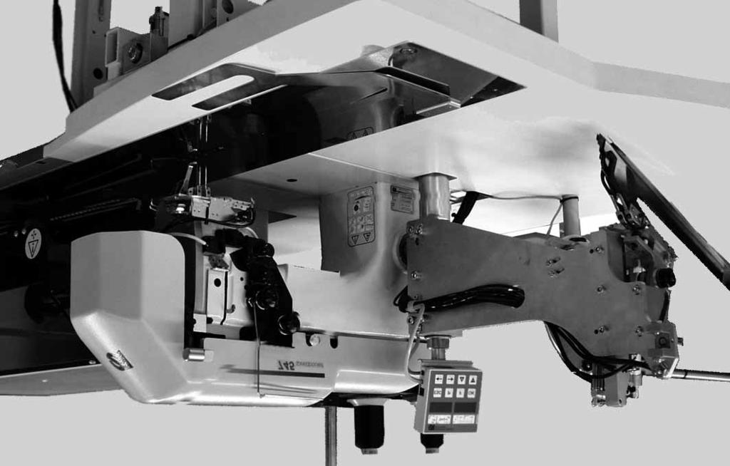
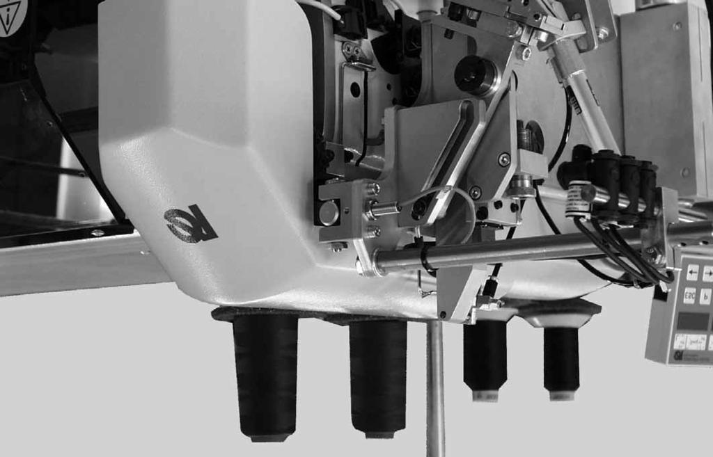
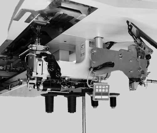
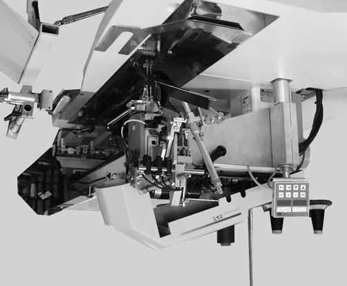
7 . Description of product. Description of proper use The Speedpocket is a sewing unit determined to sew light to medium-weight material, i.e. fabrics made of textile fibers or leather. These materials are used in the clothing industry. Generally only dry material should be processed with this machine. It should not contain any hard objects. In general, the seam is made with core thread, Polyester fibre or cotton threads. The dimensions for needle and hook threads can be taken from the table in chapter 2.4. Before using any other threads it is necessary to estimate the consequent risks and to take corresponding safety measures, if required. This sewing unit must be installed and operated in dry and well-kept rooms only. If it is operated in other rooms, which are not dry and well-kept, further measures, which are to be agreed upon, can become necessary (see EN :999). We, as a manufacturer of industrial sewing machines, take it for granted that at least semi-skilled operators will be working on our products so that we can assume that all usual operations and, where applicable, their risks are known to them..2 Brief description The Dürkopp-Adler S is a sewing unit for runstitching of rectangular piped pockets. The piping strips and additional parts are fed manually. Pocket length mm (with flap 80 mm max.). Machine head Twin needle lockstitch execution Large vertical hooks Externally driven center knife Thread trimming device for needle and hook threads Thread monitor for the needle threads DC direct sewing drive Step motors for the material feed New generation of control DAC III (DÜRKOPP ADLER Control) The comprehensive testing and monitoring system MULTITEST is integrated in the DAC III. A microcomputer assumes the control tasks, monitors the sewing cycle and indicates faulty operation and malfunctions on the display. 5
8 Optional equipment See chapter.4 (Optional equipment of class S). Sewing equipment and folders Information about sewing equipment and folders for the various fields of application can be taken from the Equipment Sheets of class S. Please address your enquiries to the DÜRKOPP-ADLER-sales offices..3 Technical data Machine head: Class Needle system: Needle distance: 0, 2 mm Needle size: Nm 80 to Nm 0 Threads: see table chapter 2.4 Stitch type: Twin needle lockstitch Speed: min r/ min max r/ min Stitch length: min. 2.0 to 3.0 mm Number of stitches condensed stitches: - 0 stitches Number of stitches bartack stitch: 0-5 stitches Number of stitches condensed stitches / bartack: mm Pocket length: max. 200 mm Operating pressure: Air consumption: 6 bar approx. 6 NL per work cycle Nominal voltage: x 230 V (50/60 Hz) Dimensions: 540 x 20 x 200 mm (L x W x H) Working height: mm (upper edge of table top) Weight: 240 kg 6
9 .4 Optional equipment Order No. Optional equipment Mounting kit K Flap clamp, left, for jackets Mounting kit K Flap clamp, right, for trousers Pincer stacker Universal stacking device (pincer stacker) for stacking to the side Pressure line Connection hose to the pneumatic supply line with corresponding couplings Remaining bobbin thread monitor Bundle clamp with rest table for trousers parts. incl. table extension (large) Blowing device For blowing out the finished parts Vacuum blower for the suction device, if there is no central vacuum system Suction device (Vacuum) For more exact positioning of the material, for connection to the central vacuum system. Note: If there is no central vacuum system available, the vacuum blower has to be ordered in addition Kit 2 nd light barrier for applications Trouser / Jacket 7
10 2 8
11 2. Operation 2. Swinging the folding station aside For work at the sewing point (threading in the needle threads, needle change etc.) the whole folding station with folder and light-barriers can be swung out to the right side. Swingthecompletefoldingstationwithfolder to the right. Hint: With the sewing unit turned on, a safety message appears on the screen of the control panel. E r r 9002 Folding station swung out The sewing point is freely accessible. Swinging the folding station back Swing the folding station back. ATTENTION! After the folding station has been swung back, it must lock in catch 2. 9


12 2.2 Pushing the covering hood back and removing the fabric sliding sheet Caution: Danger of injury! Switchthemainswitchoff. Push the covering hood back and remove the fabric sliding sheets only with the sewing unit switched off. Switchthemainswitchoff. 2 3 Pushing the covering hood back Loosen screw of covering hood 2. Push the covering hood 2 to the left. ATTENTION! Push the covering hood 2 to the left only so far that the cable 3 of the light-barrier is not damaged. Push the covering hood 2 back to the right again. Secure the covering hood 2 against displacement with the screw. Note! With the covering hood pushed back, a safety message appears on the screen of the control panel. E r r 9004 Covering hood not pushed back. 0


13 6 5 4 Removing the fabric sliding sheet For changing the hook thread bobbins: Swing the folding station 4 out by 90. Lift the fabric sliding sheet 6 in the area of pin 5 and swivel it away to the left. For complete removal (for maintenance and setting work): Remove the fabric sliding sheet.
14
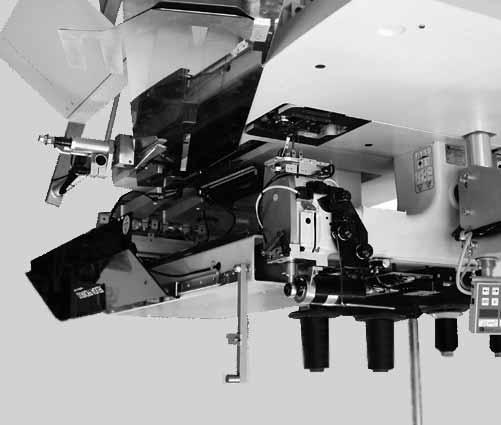
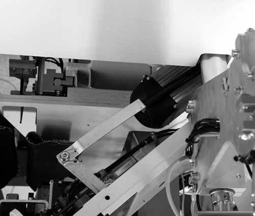
15 2.3 Tilting the machine head up For maintenance work the machine head can be tilted up. For this purpose the transport carriage must be in its rear position. Caution: Danger of injury! Switchthemainswitchoff. Tilt the machine head up only with the main switch turned off. Tilting the machine head up Remove the covering hood. For this purpose lift the covering hood at the front so that the locking is released. Lift the covering hood off carefully. Swing the folding station 2 out by 90. Swivel the locking lever 4 up. Lift the fabric sliding sheet 3 at the front and swivel it to the left. Lift the machine head in the area of the head cover and tilt it up carefully until catch 5 locks. The latch snaps in additionally. The space under the machine table is accessible for cleaning work. Swinging the machine head back Lift catch 5. Swing the machine head back carefully. Caution: Danger of injury! Hold the machine head tight until it is completely at rest when lowered. Danger of squashing your fingers between machine head and table top. Insert the fabric sliding sheet. Swivel the locking lever 4 down. Tilt the folding station 2 back and insert it. Put the covering hood on again. 3
16 50/3-70/3 40/3-60/3 40/4-60/4 2.4 Needles and Threads Needle system: Recommended needle size: Nm 90 for thin material Nm 00 for medium-weight material Nm 0 for heavy-weight material High sewing security and good sewability are achieved with the following core threads: Two-ply Polyester Continuous Polyester core-spun (e.g. Epic Poly-Poly, Rasant x, Saba C,...) Two-ply Polyester Continuous Cotton core-spun (e.g. Frikka, Koban, Rasant,...) In case these threads are not available, the Polyester fibre or cotton threads listed in the table can also be sewn. Often two-ply core threads are offered by the thread manufacturers with the same designation as three-ply Polyester fibre threads (3cyl.-spun). This causes uncertainty with regard to twisting and thread thickness. When in doubt unravel the thread and check if it is twisted 2- or 3-ply. The label no. 20 on the thread reel of a core thread corresponds e.g. to the thread size Nm 80/2 (see table values in brackets). In case of monofilament threads it is possible to use needle threads and hook threads of the same size. The best results are achieved with soft and elastic threads (software) of the thread size 30 Denier. Recommended thread sizes: Needle size Core thread Core thread Nm Needle thread Hook thread Needle thread Hook thread Polyester Polyester Polyester Cotton continuous core-spun continuous core-spun Label No. Label No. Label No. Label No (Nm 80/2) 20 (Nm 80/2) 20 (Nm 80/2) 20 (Nm 80/2) (Nm 65/2) 00 (Nm 65/2) 00 (Nm 65/2) 00 (Nm 65/2) 0 75 (Nm 50/2) 75 (Nm 50/2) 75 (Nm 50/2) 75 (Nm 50/2) Needle size Polyester fibre thread Cotton thread Nm (3cyl.-spun) Needle thread Hook thread Needle thread Hook thread B B B 90 Nm 80/3-20/3 Nm 80/3-20/3 Ne 00 Nm 70/3-00/3 Nm 70/3-00/3 Ne 0 Nm 50/3-80/3 Nm 50/3-80/3 Ne B B B Ne 50/3-70/3 Ne 40/3-60/3 Ne 40/4-60/4 4
 The needles are freely accessible.")
. Tighten screw 2. ATTENTION!")
17 Changing the needles Caution: Danger of injury! Switchthemainswitchoff. Change the needles only with the main switch turned off. Danger of cutting your fingers! Do not reach into the area of the center knife 3 when changing the needles. Swing the folding station aside (see chapter 2.) The needles are freely accessible. Loosen screw 2 and remove the needle from the needle holder. Insert the new needle in the drill-hole of needle holder as far as it will go. ATTENTION! Seen from the operator s side, the hollow groove 4 of the left needle must point to the left and the hollow groove 5 of the right needle to the right (see sketch). Tighten screw 2. ATTENTION! After changing over to another needle size the needle protection on the hook has to be readjusted (see Service Instructions). Hint: The standard needle size of class is Nm 00. 5


18
19 2.5 Threading in the needle thread Caution: Danger of injury! Switchthemainswitchoff. Thread needle threads in only with the sewing unit switched off. The threading-in of the needle threads is done in ascending numerical order, as shown in the illustrations opposite: Swing the folding station aside Left needle Put the thread reel on the thread reel holder. Thread the thread from the thread reel through the drill-hole of the thread reel holder. Guide the thread through the guide 2. Guide the thread through the drill-hole in support plate 3. Guide the thread through the guide 5. Guide the thread through the tensions discs of needle thread tension 6. Guide the thread through the thread controller spring 8. Guide the thread through the drill-hole in support plate 0. Thread the thread through the drill-hole in thread lever 7. Guide the thread downward through the thread puller 6. Thread the thread through the guide 5, through the needle thread monitor 4 and through the thread guide 3 (not visible). Thread the thread through the guide 2 (not visible), through the drill-hole in the needle holder and through the eye of the needle. Right needle Put the thread reel on the thread reel holder Thread the thread from the thread reel through the drill-hole of the thread reel holder. Guide the thread through the guide 2. Guide the thread through the drill-hole in the support plate 3. Thread the thread through the tension disc of the needle thread tension 4. Thread the thread through the guides 5 and 7. Guide the thread through the thread controller spring 9. Guide the thread through the drill-hole in support plate 0. Thread the thread through the drill-hole in the thread lever 7. Thread the thread downward through the thread puller 6, through the guide 5, through the needle thread monitor and through the thread guide 3. Thread the thread through the guide 2 (not visible), through the drill-hole in the needle holder and through the eye of the needle. Clamp the threads in the needle thread catcher and cut them off. 7


20 2.6 Winding up the hook thread The external bobbin winder allows to wind up the hook threads independent of sewing. Remove remaining thread from the winder hubs before winding-up. Put the thread reel on the thread reel holder. Thread the thread through the drill-hole of the unwinding arm (see picture on the left). Guide the thread through the guide 4. Guide the thread through the bobbin thread tension 2. Prewind the thread to the right in the front and hind reserve grooves of the bobbin hub. The full reserve grooves guarantee a secure winding even with monofilament threads. Press the bobbin retainer 3 against the bobbin hub. The winder starts. After reaching the set bobbin filling quantity the winder stops automatically. See the Service Instructions for setting the bobbin filling quantity. 8
21 2.7 Changing the bobbins 2 ATTENTION! Switch the main switch off before changing the bobbins. After a certain number of seams the hook thread stock on the bobbin is used up. With the remaining thread monitor switched on the message Err 9602 appears on the screen. After the corner incision the workpiece is moved out or stacked respectively. The sewing unit can only be restarted after the bobbin change. (See chapter Setting the number of stitches ). Removing the empty bobbin Switchthemainswitchoff. If the transport carriage is in front position, push it to the rear by hand. Swing the folding station aside. Lift the fabric sliding sheet and swivel it to the left (see chapter 2.2). Lift the upper part of the bobbin case in the area 2. The bobbin case retainer is lifted simultaneously. Remove the upper part of the bobbin case together with the empty bobbin. Remove the empty bobbin from the upper part of the bobbin case. 9


22 2 5 6 Inserting a full bobbin Insert a full bobbin in the upper part of the bobbin case 2. Pull the thread through slit 5 under tension spring 6. Pull a thread length of approx. 4 cm out of the upper part of the bobbin case. When the thread is being pulled off, the bobbin must turn in the direction of the arrow (in the opposite direction to the hook rotation). Insert the upper part of the bobbin case 2 with the full bobbin in the lower part of the bobbin case. Close the bobbin case retainer. Put the fabric sliding sheet on again. Switchthemainswitchon. Start a new sewing cycle. The stitch counting has been reset to the old value. (see Programming Instructions Adjusting programs) 20


23 2.8 Thread tension The interlacing of the threads must lie in the middle of the workpiece. Thick and hard material requires a tighter thread tension than thin and soft material. In case of thin material a too high thread tension can lead to undesired ruffling and thread breakage Setting the brake spring 4: In case of a positioned stop of the machine head the brake spring 4 avoids an after-run of the hook thread bobbin. Set the brake spring 4 by alignment. The brake power is adjusted correctly when the brake spring 4 projects approx. mm above surface 3. When setting the tension spring 6 the brake power is to be taken into account. Setting the tension spring 6: First set only a minimum tension of leaf spring 6 at the adjusting screw 5. Increase the hook thread tension: Turn to the right Reduce the hook thread tension: Turn to the left With the bobbin inserted and the hook thread threaded through the throat plate a uniform and easy pull-off must be assured. Setting the needle thread tension: Adjust the needle thread tension until a uniform stitch pattern is achieved. Adjust the tension of the needle threads at knurled nut (right needle thread) and knurled nut 2 (left needle thread). Increase the needle thread tension: Turn to the right Reduce the needle thread tension: Turn to the left 2

24 2.9 Stacking control The reflected light-barrier monitors the stacking of the sewn workpiece. The transport carriage does not run back before the workpiece has been moved out correctly. 3 2 If the workpiece is not moved out correctly, the light beam between the reflected light-barrier 3 and the reflector remains interrupted. A renewed starting is not possible. After stepping on the pedal an error message appears. If thebtfe foil 2 is worn, it has to be replaced. TheBTFE foil has the following functions: Better withdrawal of material Light beam interruption when the cover is open Caution: Danger of injury! Do not reach into the run area of the transport carriage when removing the workpiece. In case of sewing programs with automatic carriage return the transport carriage moves to the front after release of the light beam. Remove the workpiece out of the light beam. A new sewing cycle can be started. ATTENTION! For a secure function of the stacking control clean the lens of the reflected light-barrier with a soft cloth once a day. 22

25 2.0 Corner knife station The S is equipped with a manual corner knife station. The setting of the corner knives with regard to the pocket length is done by adjusting the knife block. The distance of the corner knives to the seam is manually adjustable. The whole knife block can be tilted out in order to make adjusting and service work possible. 23

26 2.0. Swinging the corner knife station out / in Caution: Danger of injury! Switchthemainswitchoff. Swing the corner knife station out only with the sewing unit switched off. Swinging the corner knife station out Swing the corner knife station out to the left. The knives are accessible for adjusting and service work. Swinging the corner knife station in Swing the corner knife station back under the sewing unit and let it catch. ATTENTION! The corner knife station must audibly lock when being pushed in. Hint: If the corner knife station is swung out with the sewing unit switched on, the following message appears: Err
 Setting the angle of the corner knives The angle of the corner knife is adjusted by turning the knife blocks 2 and 4. Loosen screws and 3.")
.")
27 2.0.2 Adjusting the corner knives Caution: Danger of injury! Switchthemainswitchoff. Adjust the corner knives only with the sewing unit switched off. Swing the corner knife station out (see chapter 2.0.) Setting the angle of the corner knives The angle of the corner knife is adjusted by turning the knife blocks 2 and 4. Loosen screws and 3. Turn the knife blocks 2 and 4 equally. Tighten screws and 3. Adjust the angle of the other pair of knives correspondingly. Height of the corner knives The corner knives are not height-adjustable. The knives always cut through completely. Swing the corner knife station in (see chapter 2.0.). Seam beginning Seam end Straight pocket corners Right and left corner knife incisions lie parallel Position of the adjustable knife block The position of the adjustable knife block corresponds to the seam length L. Loosen clamping lever 5 and set seam length L on scale 6. Tighten clamping lever 5. 25
28 2. Reference position - Starting the sewing cycle - Quick stop Reference position The reference position is necessary in order to get a defined initial position. Switchthemainswitchon. The control is initialized. The display shows briefly bf4 (Program version) 745 (Program number) The control checks whether the transport carriage is in its rear end position. If not, the message Reference run is shown on the screen. ref Step back on the pedal. The reference run starts. The transport carriage runs in its rear end position. The display changes over to the seam program set before (e.g. L -80 mm). Starting the sewing cycle Step forward on the pedal. By repeated stepping on the left pedal the various steps of the positioning sequence are started sequentially. For positioning corrections: Step back on the pedal. The last step of the positioning sequence is undone. A new positioning can be made. Step forward on the pedal. The sewing cycle is started. Quick stop The safety system of the S offers two possibilities for an immediate shut-down of the sewing unit in case of faulty operation, needle breakage, thread breakage etc.: Step back on the pedal. The current step of the positioning sequence or the sewing cycle respectively is stopped immediately. The following message appears: Err 960 Step back on the pedal again. The carriage runs out of the feeding area. Press key RST on the control panel. The current sewing cycle is stopped. 26
29 2.2 Flap and piping projection For the unhindered passage of the workpieces at the folder the maximum projections of piping, flap and material thickness (see sketch) must not be exceeded. Please take the maximum allowable piping strip widths for the respective sewing equipment (E-No.) from the Equipment Sheets of the a b : Folder 2: Piping projection, max. 40 mm 3: Flap 4: Guide plate on the folder 5: Flap projection, max. 20 mm 6: Piping strip NA NA: Seam distance a, b: Material passage on the folder Setting the sewing depth of flap Stop guide 3 determines the sewing depth and thus the flap projection. Loosen screws 2 and 4. Adjust stop guide 3 Tighten screws 2 and
30 2.3 Piping strip length The length of the piping strip must be dimensioned in such a way that it projects approx. 20 mm beyond the seam beginning and seam end. Thus the piping strip length is as follows: Piping strip length = Sewing length + 2 x 20 mm 28
31 2.4 Working method Working method Remarks A Piped pockets, manual positioning of piping strips, flaps and other additional parts On the following pages the working method is described. The description is divided into the following items: Positioning points This item indicates which positioning points are used for the various workpieces (e.g. left and right pieces). Aligning the positioning aids This section describes the adjustment and alignment of the positioning aids (e.g. positioning marks, marking lamps, stop guides etc.). Positioning and starting the sewing cycle Under this item the individual positioning steps are listed with common positioning examples. Caution: Danger of injury! Do not reach under the downholder, the feeding clamp and the folder during the positioning process. 29
32 2.4. Working method (Production of trousers) Possible processing variants Front trousers pockets with pocket bag positioned below Hind trousers pockets with or without flap, with pocket bag positioned below Positioning method Example: Hind trousers without flap, with pocket bag positioned below st step: Select the pocket program on the control panel Push the pocket bag under pocket bag clamp and position it at the marks 2. As marks you can use e.g. adhesive tape attached to the fabric sliding sheet. 2nd step: Position hind trousers at the rear positioning point 4 and at mark 3. Touch the pedal. The hind trousers is firmly clamped in its position by the fabric downholder 5. Smooth out the clamped hind trousers in the area of the dart. 3rd step: Touch the pedal. The feeding clamps run forward and lower onto the workpiece. A separate lowering of the clamp halves can be programmed. For example: the right clamp lowers and the fullness from the trousers is manually smoothed out to the left. Then lower the left clamp. Position the piping strip 7 on the feeding clamps flush at the front edges 8. The alignment of the various piping types on the feeding clamps is described more precisely in the following. See Positioningthepipingstrip. Touch the pedal. The folder 6 lowers. Touch the pedal once again. Thesewingcyclestarts. 30


33 st step: 2 2nd step: rd step:
34 Positioning the piping strip Double piping: Position the piping strip centered on the feeding clamps and flush at the front edges. Left single piping with separately positioned right facing: Position the piping strip on the left feeding clamp flush with the cutting line. Position the facing on the right feeding clamp. This positioning method requires the flap clamp right (Order No ) available as optional equipment. The edges and 2 have to be sufficiently caught by the needle, but must not be cut by the center knife. 2 Left single piping with grown-on facing Positionthepipingstripatthestopguide3ontheleftfolding sheet.. ATTENTION! In case of grown-on facings the right folding sheet must not close. Pull off the hose coupling from the right feeding clamp 3 32
 Or Left flap clamp (Order No. 0792 06) 2.4.2. Sewing without light-barrier 2 Form stop for the flap The unmachined part is delivered with the flap clamp 2.")
35 2.4.2 Sewing with flap For the simultaneous sewing-in of flaps or other additional parts the following optional equipment is required according to the field of application: Production of trousers: Right flap clamp (Order No ) Or Left flap clamp (Order No ) Sewing without light-barrier 2 Form stop for the flap The unmachined part is delivered with the flap clamp 2. It has to be machined as a form stop corresponding to the flap used. ATTENTION! The flap length must correspond to the desired length of the pocket opening. 33
36 Sewing with the flap at the right (production of trousers) For the production of trousers always position the flap at the Rear positioning point (light spot 5). The Rear positioning point applies as a fixed point also for other sewing units (further flap lengths). Attach the positioning mark 4 for the hind trousers to the fabric sliding sheet. The sketch shows the positioning of a right hind trousers part 3 with flap. Position the left hind trousers parts in reflected image. The position of the flap remains unchanged

37 Sewing with light-barrier 2 When attaching flaps, seam beginning and seam end are recognized by a light-barrier. Positioning the flap The positioning marks and 2 on the folder limit the sewing area for the attaching of flaps. Always position the flaps within the marked area. If the flap is not positioned correctly, the error message Err 972 or Err 9722 appears. Correction of seam beginning and seam end The correction of the seam beginning (NA) and seam end (NE) when sewing with light-barrier is done in the pocket correction program (see Programming Instructions). 35
38 3. Functions and operation of the optional equipment In this chapter the function and the operation of the most important optional equipment is described. 3. Remaining thread monitor The remaining thread monitor monitors the left and right hook thread bobbin with the infrared reflected light barriers and When the bobbin is empty, the light beam transmitted by the light barrier or 2 is reflected by the exposed reflecting surface 3 of the bobbin hub. The display of the control box shows the message Info 3220" Additionally a flashing symbol indicate the position of the empty bobbin. left bobbin empty right bobbin empty The pocket opening is safely finished with the thread in the reserve groove of the bobbin hub. Caution: Danger of injury! Switchthemainswitchoff. Clean the lenses of the light barriers only with the sewing unit switched off. Switchthemainswitchoff. Clean the lenses of the light barrier with a soft cloth after every bobbin change. Switchthemainswitchon. Start a new sewing cycle. 36
39 3.2 Aligning the light barriers of the bobbin thread monitor 3 2 Standard checking The light barrier holders 3 and 5 are adjusted by the manufacturer in such a way that there is a sufficient safety distance of 3,5 mm between the revolving hooks and the light barriers 2 and 6. ATTENTION! The bobbin thread monitor is only effective when the function is activated. Activated with parameter 408 = (see the programming instructions, chapter 4 Structure of menu ). Switch on the main switch. Choose Multitest 953 (see programming instructions, chapter 4 Structure of menu ). Remove the bobbin case top part with bobbin. Insert an empty bobbin in the bobbin case bottom part. ATTENTION! External light influences the sensitivity of the light barrier. 37
, thenaline( ) will be displayed. You will hear a beep at the same time.")
40 7 If the alignment is correct: a reflection occurs at the surface 7 of the bobbin hub when an empty bobbin rotates. The figure between and 5 will show the intensity of the reflection. If the value is above ( 8 ), thenaline( ) will be displayed. You will hear a beep at the same time. left bobbin right bobbin actual reflection value 3 no line, value <8 line, when value >8 actual reflection value 5 Hint: If the light barriers are set properly, the maximal value of 5 must be reached when the infrared ray hits the surface of the bobbin hub. To exit the test program switch off the machine. Correction Clean the lenses of the light barriers 2 and 6 as well as the reflection faces 7 of the bobbin hubs with a soft cloth. Loosen the clamping screw and 4 respectively. Align the light barrier 2 and 6 respectively by a minimum rotary motion on the holders 3 or 5. The infrared ray of light barrier 2 or 6 must hit the bobbin hub through the light window in the bobbin case without hindrance. Tighten clamping screw and 4 respectively. Check the alignment of the two light barriers once again
 is used in conjunction with the bundle")

41 3.3 Blowing device The blowing device (Order No ) is used in conjunction with the bundle clamp (Order No ). The blower pipe conveys the workpiece out of the sewing area. Y02 P blower 39

42 3.4 Bundle clamp Bundle clamp (Order No ) 2 Caution: Danger of injury! Risk of suffering from bruising between the arms of the bundle clamps. Function and operation Step the foot switch down and hold it down. The bundle clamp opens. Hang the hind trousers parts in bundle clamp. The bundle clamp closes. Release the foot switch. Place the clamped hind trousers parts on the table extension 2 (Order No ). After blowing out, the hind trousers part hangs down on the bundle clamp then. 40

43 3.5 Mounting table extensions 3 2 Fasten the table extension 3 onto the table top brace with the screws 2. Loosen screws slightly. Create a clearance to the table top by shifting the table extension 3. This clearance is required for the free passage of the positioned pocket bag. 4
44 3.6 Vacuum blower The vacuum blower has to be ordered under the order number it is required for an accurate positioning of the workpieces, if no central vacuum system is available. Switching on the vacuum blower Switch on switch at the control box of the vacuum blower. 42

45 3.6. Checking the nominal voltage of the vacuum blower (optional equipment) ATTENTION! Any work on the electrical equipment of the sewing unit must only be carried out by electricians or correspondingly instructed persons. The mains plug must be pulled out. The adaptation to the local mains voltage has to be done at the terminal strip in control box. Screw off the cover of control box. Check the arrangement of the connections to the terminal strip. (see circuit diagram). If necessary, change the connections according to the local mains voltage. Put the cover on the control box again and screw on Direction of rotation of the vacuum blower The direction of rotation of the vacuum blower can be inverted by exchanging the phase (plug). 43

 in front of filter (white) for use with central vacuum system. 2 3 ATTENTION!")
46 3.6.3 Connection to the factory-own vacuum system The suction device facilitates the precise feeding and positioning of the workpiece on the work table. Connect the hose of the factory-own vacuum system to the connection valve 3. Note: In case no factory-own vacuum system is available, the vacuum blower (Order No ) has to be ordered in addition. Only filter (white) for use with vacuum blower (Order No ). Seal (black) in front of filter (white) for use with central vacuum system. 2 3 ATTENTION! When fitting the vacuum blower,it is absolutely necessary to remove the seal 2 (black) from the valve. Only the filter (white) should be attached to the valve. 44


 X00t X00t Connection")
47 3.7 Mounting the 2 nd light barrier Front view Bottom view S = Light barrier LS S2 = Light barrier LS2 (Test program 952) (Test program 954) X00t X00t Connection second light barrier 45


48 4. Maintenance Caution: Danger of injury! Switchthemainswitchoff. Maintenance work must only be done with the sewing unit switched off. 4. Cleaning A clean sewing unit protects from malfunctions! Clean and check daily: Clean the area around the hooks and 2 with the compressed air pistol On each bobbin change, clean the lenses of the light barriers 5 and 6 of the thread monitor with a soft cloth. Cleanthefilterring7onthevacuumvalve8: Blow it with an air gun

49 Clean and check daily: Check the water level in the pressure regulator. The water level must not reach the filter element. After screwing in the drain screw blow the water out of the water separator 2 under pressure. The filter element separates dirt and condensed water. After a certain operating time wash the dirty filter tray and the filter element with benzine and blow clean with the compressed air pistol. ATTENTION! Do not use any solvents for washing out the filter tray and the filter element! They destroy the filter tray. 2 47
.")

50 3.2 Weekly lubrication For lubricating the sewing unit use exclusively the lubricating oil DA-0. DA-0 can be obtained from the sales offices of DÜRKOPP ADLER AG. Check the oil level in the oil reservoir 3 for lubrication of the machine head Tilt the machine head up (see chapter 2.3). The oil level in the oil reservoir 3 must not drop below the Min marking. If necessary, fill some oil up to the Max marking through the drill-hole in the inspection glass. Check the oil level in the oil reservoir 5 for lubrication of the hook Tilt the machine head up (see chapter 2.3). Fill the oil reservoir 5 with oil up to the Max marking through the nipple 4 (see sketch)
Speedpocket. Sewing unit for runstitching of rectangular piped pockets. Operating Instructions. Installation Instructions. Service Instructions
 745-34 Speedpocket Sewing unit for runstitching of rectangular piped pockets Operating Instructions Installation Instructions Service Instructions Instructions for programming DAC 1 3 4 Postfach 17 03
Instructions, complete. Operating Instructions. Installation Instructions. Service Instructions
 506-3 Instructions, complete Operating Instructions Installation Instructions Service Instructions 2 3 Postfach 7 03 5, D-33703 Bielefeld Potsdamer Straße 90, D-3379 Bielefeld Telefon +49 (0) 52 / 9 25-00
CNC Knopfannähautomat CNC Automat for Button Sewing
 531 CNC Knopfannähautomat CNC Automat for Button Sewing Bedienanleitung / Operating Instructions Aufstellanleitung / Installation Instructions Serviceanleitung / Service Instructions 1 3 Postfach 17 03
Spezialnähmaschine. Betriebsanleitung. Instruction manual
 171 173 Spezialnähmaschine Betriebsanleitung Instruction manual D GB Postfach 17 03 51, D-33703 Bielefeld Potsdamer Straße 190, D-33719 Bielefeld Telefon +49 (0) 521 / 9 25-00 Telefax +49 (0) 521 / 9 25
Spezialnähmaschine. Betriebsanleitung. Instruction manual
 669 Spezialnähmaschine Betriebsanleitung Instruction manual D GB Postfach 17 03 51, D-33703 Bielefeld Potsdamer Straße 190, D-33719 Bielefeld Telefon +49 (0) 521 / 9 25-00 Telefax +49 (0) 521 / 9 25 24
Spe ci al se wing ma chi ne
 267 Spe ci al se wing ma chi ne CN In struc tions for ope ra ting GB Post fach 17 03 51, D-33703 Bie le feld Pots da mer Stra ße 190, D-33719 Bie le feld Te le fon + 49 (0) 5 21 / 9 25-00 Te le fax + 49
Spezialnähmaschine. Betriebsanleitung. Instruction manual
 869 Spezialnähmaschine Betriebsanleitung Instruction manual D GB Postfach 17 03 51, D-33703 Bielefeld Potsdamer Straße 190, D-33719 Bielefeld Telefon +49 (0) 521 / 9 25-00 Telefax +49 (0) 521 / 9 25 24
Spezialnähmaschine. Betriebsanleitung. Instruction manual
 669 Spezialnähmaschine Betriebsanleitung Instruction manual D GB Postfach 17 03 51, D-33703 Bielefeld Potsdamer Straße 190, D-33719 Bielefeld Telefon +49 (0) 521 / 9 25-00 Telefax +49 (0) 521 / 9 25 24
Part 2: Installation Instructions cl
 Contents Page: Part 2: Installation Instructions cl. 381-382 1. Delivery scope............................... 3 2. General and Transportation safety precautions........... 3 3. Stand installation 3.1 Installing
888 Operating Instructions
 888 Operating Instructions All rights reserved. Property of Dürkopp Adler AG and copyrighted. Reproduction or publication of the content in any manner, even in extracts, without prior written permission
Spezialnähmaschine. Bedienanleitung. Operating Instructions. Instructions de maniement
 367 Spezialnähmaschine Bedienanleitung Operating Instructions Instructions de maniement D GB F Postfach 17 03 51, D-33703 Bielefeld Potsdamer Straße 190, D-33719 Bielefeld Telefon +49 (0) 5 21/ 9 25-00
IMPORTANT SAFETY INSTRUCTIONS
 CONTENTS 1.SPECIFICATIONS... 1 2.INSTALLATION... 1 3.INSTALLATION OF THE SYNCHRONIZER... 2 4.ASSEMBLY OF HAND WHEEL... 2 5.INSTALLATION OF HAND WHEEL... 2 6.INSTALLING THE BELT COVER... 3 7.ADJUSTING THE
DA-9270 TWIN NEEDLE (THREE NEEDLE) FEED OFF THE ARM DOUBLE CHAIN STITCHER. English
 FEED OFF THE ARM DOUBLE CHAIN STITCHER. English") TWIN NEEDLE (THREE NEEDLE) FEED OFF THE ARM DOUBLE CHAIN STITCHER English Thank you very much for buying a BROTHER sewing machine. Before using your new machine, please read the safety instructions below
TWIN NEEDLE (THREE NEEDLE) FEED OFF THE ARM DOUBLE CHAIN STITCHER English Thank you very much for buying a BROTHER sewing machine. Before using your new machine, please read the safety instructions below
Part 1: class 69 operating instructions
 Contents Page: Preface and general safety instructions Part 1: class 69 operating instructions 1. Product description............................ 5 2. Designated use.............................. 5 3.
Please read this manual before using the machine. Please keep this manual within easy reach for quick reference.
 DA-927A DA-928A INSTRUCTION MANUAL Please read this manual before using the machine. Please keep this manual within easy reach for quick reference. TWIN NEEDLE / THREE NEEDLE FEED OFF THE ARM DOUBLE CHAIN
Special Sewing Machine
 884 Special Sewing Machine Instruction manual Postfach 17 03 51, D-33703 Bielefeld Potsdamer Straße 190, D-33719 Bielefeld Telefon +49 (0) 521 / 9 25-00 Telefax +49 (0) 521 / 9 25 24 35 www.duerkopp-adler.com
M-TYPE CLASSIC M-TYPE PREMIUM. Additional Instructions. Electropneumatic needle cooling
 M-TYPE CLASSIC M-TYPE PREMIUM Additional Instructions Electropneumatic needle cooling IMPORTANT READ CAREFULLY BEFORE USE KEEP FOR FUTURE REFERENCE All rights reserved. Property of Dürkopp Adler AG and
Please read this manual before using the machine. Please keep this manual within easy reach for quick reference.
 INSTRUCTION MANUAL Please read this manual before using the machine. Please keep this manual within easy reach for quick reference. HIGH SPEED SINGLE NEEDLE STRAIGHT LOCK STITCHER Thank you very much for
Spezialnähmaschine. Betriebsanleitung. Instruction manual
 838 Spezialnähmaschine Betriebsanleitung Instruction manual DE EN Postfach 7 03 5, D-33703 Bielefeld Potsdamer Straße 90, D-3379 Bielefeld Telefon +49 (0) 52 / 9 25-00 Telefax +49 (0) 52 / 9 25 24 35 www.duerkopp-adler.com
/11, -14/31 INSTRUCTION MANUAL. This instruction manual applies to machines from the following serial numbers onwards: #
 3834-4/, -4/3 INSTRUCTION MANUAL This instruction manual applies to machines from the following serial numbers onwards: # 2 733 53 296-2-8 936/002 Betriebsanleitung engl. 06.09 This Instruction manual
Spezialnähmaschine. Betriebsanleitung. Instruction manual
 887 Spezialnähmaschine Betriebsanleitung Instruction manual DE EN Postfach 17 03 51, D-33703 Bielefeld Potsdamer Straße 190, D-33719 Bielefeld Telefon +49 (0) 521 / 9 25-00 Telefax +49 (0) 521 / 9 25 24
PLC-1700 Series PLC-1710, , 1760, , 1760L
 Post-bed, Unison-feed, Lockstitch Machine PLC-1700 Series PLC-1710, 1710-7, 1760, 1760-7, 1760L ENGINEER S MANUAL 40040656 No.E372-00 Introduction This Engineer s Manual is for technical service engineers.
Spezialnähmaschine. Betriebsanleitung. Instruction manual
 887 Spezialnähmaschine Betriebsanleitung Instruction manual Postfach 17 03 51, D-33703 Bielefeld Potsdamer Straße 190, D-33719 Bielefeld Telefon +49 (0) 521 / 9 25-00 Telefax +49 (0) 521 / 9 25 24 35 www.duerkopp-adler.com
ENGINEER S MANUAL No.01
 1-NEEDLE, UNISON FEED, LOCKSTITCH MACHINE (AUTOMATIC LUBRICATION) LU-1510 1-NEEDLE, UNISON FEED, LOCKSTITCH MACHINE WITH AUTOMATIC THREAD TRIMMER (AUTOMATIC LUBRICATION) LU-1510-7 1-NEEDLE, UNISON FEED,
/ /020 INSTRUCTION MANUAL
 3588-05/020-15/020 INSTRUCTION MANUAL This instruction manual applies to machines from serial number 2 760 129 and software version 0380/003, 0381/003 onwards 296-12-19 094/002 Betriebsanleitung engl.
Part 3: Service manual, class
 Contents Page: Part : Service manual, class 7-75. General.................................................. Gauges................................................. 4. Description and adjustment of the
Please read this manual before using the machine. Please keep this manual within easy reach for quick reference.
 INSTRUCTION MANUAL Please read this manual before using the machine. Please keep this manual within easy reach for quick reference. SINGLE NEEDLE DIRECT DRIVE STRAIGHT LOCK STITCHER WITH THREAD TRIMMER
AMS-224EN4530R / AW-3 AMS-224EN6030R / AW-3 INSTRUCTION MANUAL
 AMS-224EN4530R / AW-3 AMS-224EN6030R / AW-3 INSTRUCTION MANUAL 1 CONTENTS 1. GENERAL...1 1-1. Specifications of AW-3...1 1-2. Configuration...2 2. INSTALLATION...4 2-1. Installation procedure...4 2-2.
3590-1/ /5030 INSTRUCTION MANUAL
 3590-1/3030-2/5030 INSTRUCTION MANUAL This instruction manual applies to machines from serial number 2 770 769 and software version 0390/007 (-2/5030) and 0392/007 (-1/3030) onwards. 296-12-19 115/002
EHA Hoffmann International GmbH
 EHA Hoffmann International GmbH User manual EHA-TRANSPRINT HP 2020 Machine-No.: Year: EHA Hoffmann International GmbH Michelsbergstraße 24 D-57080 Siegen/Germany Telephone: +49 271 39 32-0 Telefax: +49
Please read this manual before using the machine. Please keep this manual within easy reach for quick reference.
 INSTRUCTION MANUAL Please read this manual before using the machine. Please keep this manual within easy reach for quick reference. ELECTRONIC DIRECT DRIVE LOCKSTITCH BUTTON HOLER Thank you very much for
KE-430HX KE-430HS BE-438HX
 KE-430HX KE-430HS BE-438HX INSTRUCTION MANUAL Please read this manual before using the machine. Please keep this manual within easy reach for quick reference. ELECTRONIC DIRECT DRIVE LOCKSTITCH BAR TACKER
CONTENTS 1. SPECIFICATIONS SET-UP FOR THE OPERATOR MAINTENANCE... 34
 ENGLISH ii CONTENTS. SPECIFICATIONS... 2. SET-UP.... Installing the motor unit... 2. Installing the control box... 3. Installing the belt... 2 4. Adjusting the pulley cover... 2 5. Installation and adjustment
Please read this manual before using the machine. Please keep this manual within easy reach for quick reference.
 INSTRUCTION MANUAL Please read this manual before using the machine. Please keep this manual within easy reach for quick reference. SINGLE NEEDLE DIRECT DRIVE LOCK STITCHER WITH ELECTRONIC FEEDING SYSTEM
Industrial Sewing Machine TECHNICAL MANUAL MECHANICAL VERSION. Electronic Pattern Sewing Machine. Model PLK-E2010R A180E530P01
 Industrial Sewing Machine TECHNICAL MANUAL MECHANICAL VERSION Electronic Pattern Sewing Machine Model PLK-E2010R A180E530P01 FOR YOUR SAFETY! If you are operating the sewing machine for first time, please
INSTRUCTION MANUAL. This instruction manual applies to machines from the following serial numbers onwards: and software version 0435/002.
 45 46 INSTRUCTION MANUAL This instruction manual applies to machines from the following serial numbers onwards: 7 6 454 and software version 0435/00. 96--9 30/00 Instruction Manual engl. 0.5 This instruction
INSTRUCTION MANUAL. This instruction manual applies to machines from the following serial numbers onwards: #
 245 246 INSTRUCTION MANUAL This instruction manual applies to machines from the following serial numbers onwards: # 6 500 24 296-2-9 99/002 Betriebsanleitung engl. 05.2 This Instruction Manual is valid
OPERATING & SERVICE PARTS MANUAL HDS-215 COMBINATION SHRINK SYSTEM
 OPERATING & SERVICE PARTS MANUAL HDS-215 COMBINATION SHRINK SYSTEM FOR HOT KNIFE AND IMPULSE MACHINES READ ALL INSTRUCTIONS CAREFULLY BEFORE OPERATING EQUIPMENT TABLE OF CONTENTS Electrical Requirements
MODEL S-311+I OPERATING INSTRUCTIONS S-311+I
 MODEL S-311+I OPERATING INSTRUCTIONS TABLE OF CONTENTS A - INTRODUCTION... 1. GENERAL INFORMATION... 2. SAFETY LABELS AND EQUIPMENT DEVICE... 3. SPECIFICATIONS... B - MACHINE ASSEMBLY... S-311+I AF -
USER S MANUAL. SS-7350 Series. Small cylinder bed interlock sewing machine
 R USERS MANUAL SS-7350 Series Small cylinder bed interlock sewing machine R Best Quality Best Price Best Service 1. Thank you for purchasing our product. Based on the rich expertise and experience accumulated
MITSUBISHI. Industrial Sewing Machine. Model PLK-E1010 TECHNICAL MANUAL MECHANICAL VERSION. Electronic Pattern Sewing Machine A180E494P01
 MITSUBISHI Industrial Sewing Machine TECHNICAL MANUAL MECHANICAL VERSION Electronic Pattern Sewing Machine Model PLK-E00 A80E9P0 FOR YOUR SAFETY! If you operate the sewing machine first time, please make
LK-1900BN Series INSTRUCTION MANUAL
 LK-1900BN Series INSTRUCTION MANUAL 1 CONTENTS I. EXPLANATION OF THE LK-1900BN, COMPUTER-CONTROLLED HIGH- SPEED BARTACKING MACHINE...1 1. SPECIFICATIONS...1 2. CONFIGURATION...2 2-1. Names of main unit...
I N ST R UC T I ON. MODEL HAB500 AroMatic TM BREAD SLICERS MODEL FORM (4-99) AROMATIC BREAD SLICER 701 S. RIDGE AVENUE TROY, OHIO
 AROMATIC BREAD SLICER 701 S. RIDGE AVENUE TROY, OHIO") I N ST R UC AROMATIC BREAD SLICER T I ON S MODEL HAB500 AroMatic TM BREAD SLICERS MODEL HAB500 ML-104845 701 S. RIDGE AVENUE TROY, OHIO 45374-0001 FORM 34198 (4-99) TABLE OF CONTENTS GENERAL..........................................................
I N ST R UC AROMATIC BREAD SLICER T I ON S MODEL HAB500 AroMatic TM BREAD SLICERS MODEL HAB500 ML-104845 701 S. RIDGE AVENUE TROY, OHIO 45374-0001 FORM 34198 (4-99) TABLE OF CONTENTS GENERAL..........................................................
MB-1800 Series INSTRUCTION MANUAL
 MB-800 Series INSTRUCTION MANUAL CONTENTS!. SPECIFICATIONS... @. NAME OF EACH COMPONENT.... Name of the main unit... #. INSTALLATION... $. PREPARATION OF THE SEWING MACHINE...7. Attaching the needle...
Thank you for purchasing Pegasus automatic unit.
 HG Series odels: HG-110/W664-08 HG-130/WT664-08 HG-140/WT664-35 Thank you for purchasing Pegasus automatic unit. Study this manual very carefully before beginning any of the procedure and then use the
RH-981A ENGLISH ELECTRONIC EYELET BUTTON HOLER
 ENGLISH ELECTRONIC EYELET BUTTON HOLER Thank you very much for buying a BROTHER sewing machine. Before using your new machine, please read the safety instructions below and the explanations given in the
Operator's Manual. Fold System multipli 35.
 Mathias Bäuerle GmbH Gewerbehallestraße 7- D-78 St.Georgen Telefon (077) 88-0 Telefax (077) 88- Internet: http://www.mbfold.de E-mail: center@mbfold.de Fold System multipli 5 Operator's Manual Operator's
Installation and Operating Instructions
 ELECTRICALLY OPERATED FOLDING STAIRS Installation and Operating Instructions Premier Loft Ladders ltd Registered Office: 2 Dawson Drive, Trimley St Mary, Felixstowe, Suffolk. IP11 0YW Registered in England
Industrial Sewing Machine TECHNICAL MANUAL SEWING MACHINE HEAD. Electronic Pattern Sewing Machine. Model PLK-G1010 A180E593P03
 Industrial Sewing Machine TECHNICAL MANUAL SEWING MACHINE HEAD Electronic Pattern Sewing Machine Model PLK-G1010 A180E593P03 FOR SAFE USE Before the installation, operation, and inspection for this product,
Glass and Dishwashers 402/452/502. (original instructions) (incl. Australian /502) Starting from Serial No.:
 (incl. Australian /502) Starting from Serial No.:") Glass and Dishwashers ECOMAX 402/452/502 (incl. Australian 452-90/502) INSTALLATION AND OPERATION INSTRUCTIONS (original instructions) Starting from Serial No.: 8663 4000 REV. 05.10.2015 EN IMPORTANT NOTES
Glass and Dishwashers ECOMAX 402/452/502 (incl. Australian 452-90/502) INSTALLATION AND OPERATION INSTRUCTIONS (original instructions) Starting from Serial No.: 8663 4000 REV. 05.10.2015 EN IMPORTANT NOTES
INSTRUCTION MANUAL. This instruction manual applies to machines from the following serial numbers onwards: and software version 0435/002.
 337 INSTRUCTION MANUAL This instruction manual applies to machines from the following serial numbers onwards: 7 6 535 and software version 0435/00. 96--9 37/00 Instruction Manual engl..5 This instruction
LK-1903B/BR35 INSTRUCTION MANUAL
 LK-1903B/BR35 INSTRUCTION MANUAL CONTENTS I. SPECIFICATIONS...1 1. Specifications... 1 2. Model classification according to the button size... 2 3. Shape of buttons... 2 II. NAME OF EACH COMPONENT...3
FD 430 Envelope Sealer
 FD 430 Envelope Sealer 1/2018 OPERATOR, MAINTENANCE, & PARTS MANUAL REV. 1 2 CONTENTS 1 SAFETY INSTRUCTIONS... 5 1.1 Symbols and reference key... 5 1.2 Basic safety precautions... 6 1.3 Safety advice...
BL Series INSTRUCTIONS
 BL Series Models: EX5204/BL514 EX5204/BL515 EX5214/BL524 EX5214/BL525 EXT5214/BL524 EXT5214/BL525 EX5404/BL614 EX5404/BL615 EX5414/BL624 EX5414/BL625 EXT5214H/BL528 EXT5214H/BL529 Automatic Backlatcher
DDL-900A INSTRUCTION MANUAL
 DDL-900A INSTRUCTION MANUAL COVERI CONTENTS I. SPECIFICATIONS... 1 II. SET-UP... 3 1. Installation...3 2. Installing the pedal sensor...4 3. Installing the power switch (for CE)...4 4. Connecting the connector...5
Post-bed, Unison-feed, Lockstitch Machine with Vertical-axis Large Hook PLC
 PLC-1700 Series Post-bed, Unison-feed, Lockstitch Machine with Vertical-axis Large Hook Most-advanced machine lineup best suited to the stitching process for heavy weight materials such as car seats and
DDL-900B INSTRUCTION MANUAL
 DDL-900B INSTRUCTION MANUAL CONTENTS I. SPECIFICATIONS... 1 II. SET-UP... 3 1. Installation...3 2. Installing the pedal sensor...4 3. Installing the power switch (for CE)...4 4. Connecting the connector...5
Please read this manual before using the machine. Please keep this manual within easy reach for quick reference.
 INSTRUCTION MANUAL Please read this manual before using the machine. Please keep this manual within easy reach for quick reference. SINGLE NEEDLE DIRECT DRIVE LOCK STITCHER WITH ELECTRONIC FEEDING SYSTEM
Model PLK-G5050 PLK-G10050
 Industrial Sewing Machine TECHNICAL MANUAL SEWING MACHINE HEAD Electronic Pattern Sewing Machine Model PLK-G5050 PLK-G10050 A180E686P01 FOR SAFE USE Before the installation, operation, and inspection for
TA-12. Tabbing System USER'S GUIDE
 TA-12 Tabbing System USER'S GUIDE SAFETY PRECAUTIONS THIS EQUIPMENT PRESENTS NO PROBLEM WHEN USED PROPERLY. HOWEVER, CERTAIN SAFETY RULES SHOULD BE OBSERVED WHEN OPERATING THE TA12 TABBER. BEFORE USING
KE-430D BE-438D ELECTRONIC DIRECT DRIVE LOCKSTITCH BAR TACKER ELECTRONIC DIRECT DRIVE LOCKSTITCH BUTTON SEWER
 KE-430D ELECTRONIC DIRECT DRIVE LOCKSTITCH BAR TACKER BE-438D ELECTRONIC DIRECT DRIVE LOCKSTITCH BUTTON SEWER Thank you very much for buying a BROTHER sewing machine. Before using your new machine, please
DDL-9000A Series. Direct-drive, High-speed, Lockstitch Machine with Automatic Thread Trimmer. High-end model of JUKI 1-needle lockstitch machines
 DDL-9000A Series Direct-drive, High-speed, Lockstitch Machine with Automatic Thread Trimmer DDL-9000A Series High-end model of JUKI 1-needle lockstitch machines A genuine sewing machine which makes the
MSK-8900M Industrial Sewing Machine. Instruction Manual
 MSK-8900M Industrial Sewing Machine Instruction Manual CONTENTS Operation instruction. Brief introduction. Main specifications. Main parts name 4. The method of installation 5 5. Pareparation before sewing
AMS-224EN6060 / IP-420 INSTRUCTION MANUAL
 AMS-224EN6060 / IP-420 INSTRUCTION MANUAL * This Instruction Manual only describes the functions which are different from those of the AMS-224EN/IP-420. In order to use the AMS-224EN6060 safely, please
Philips OneSpace luminous ceiling
 Philips OneSpace luminous ceiling Panel installation manual 2014 Koninklijke Philips N.V. 2 Philips OneSpace luminous ceiling panel installation manual March 2014 Contents 1. Welcome to the world of Philips
Industrial 3721/3741/3745/3791. Documented Quality - Stitch by Stitch
 Industrial 3721/3741/3745/3791 Documented Quality - Stitch by Stitch Documented quality The POWERLINE 3721, 3741, 3745 and 3791 are quality assurance systems designed for use on safety-relevant seams.
Industrial Sewing Machine TECHNICAL MANUAL SEWING MACHINE HEAD. Electronic Pattern Sewing Machine. Model PLK-G2516 A180E621P01
 Industrial Sewing Machine TECHNICAL MANUAL SEWING MACHINE HEAD Electronic Pattern Sewing Machine Model PLK-G2516 A180E621P01 FOR SAFE USE Before the installation, operation, and inspection for this product,
Installation Instructions
 GE Consumer & Industrial Appliances Installation Instructions Junction Box Cover Within this user bag, you will find a junction box cover and a #10 hex head screw used to attach the junction box cover
Technical Data. Name: ERIKA Automat fully automatic machine to divide and to round dough pieces of the same size
 AUTOMAT MANUAL 1 Technical Data Name: ERIKA Automat fully automatic machine to divide and to round dough pieces of the same size Type Divisions Dough Portions (in ounces) Plate Nos. 3 30 1.0 3.5 #35 4/40A
DDL-8700B-7 INSTRUCTION MANUAL
 DDL-8700B-7 INSTRUCTION MANUAL I CONTENTS I. SPECIFICATIONS... 1 II. SET-UP... 3 1. Installation...3 2. Installing the pedal sensor...4 3. Connecting the connector...4 4. How to install the power plug...5
BAS-300G-484 BAS-300G-484 SF
 BAS-300G-484 BAS-300G-484 SF DIRECT DRIVE PROGRAMMABLE ELECTRONIC PATTERN SEWER Please read this manual before using the machine. Please keep this manual within easy reach for quick reference.
Test Unit GTL 100 for Fire Detectors
 Test Unit GTL 100 for Fire Detectors Description and Operation Manual Zertifiziertes QM System Nach DIN EN ISO 9001 Description and Operation Manual Table of Contents 1. Instructions 1.1 General 1.2 Standards
Built-In Dishwasher. Installation Instructions. BEFORE YOU BEGIN Read these instructions completely and carefully. IMPORTANT The dishwasher MUST be
 Installation Instructions Built-In Dishwasher If you have questions, call 800.GE.CARES (800.432.2737) or visit our website at: www.ge.com BEFORE YOU BEGIN Read these instructions completely and carefully.
Instruction Manual 使用说明书
 Instruction Manual 使用说明书 7700 High Speed Overlock Sewing Machine 高速包缝机 GB CN Installation Instructions 安装须知 Operating Instructions 操作须知 Basic Service Instructions 基本维修须知 Edition/ 版本 :07/006 Printed in
MODEL CBS 13 BUTTON SEWING AND NECK WRAPPING PARTS AND SERVICE MANUAL PART NUMBER MACHINE SERIAL No:
 MODEL CBS 13 BUTTON SEWING AND NECK WRAPPING PARTS AND SERVICE MANUAL MACHINE SERIAL No: PART NUMBER 97.7300.0.000 This manual is valid from the machine Serial No.: T CBS0002 10 / 2017 MODEL MODEL CBS
DOCUMENT CREASING MACHINE
 DOCUMENT CREASING MACHINE OPERATORS MANUAL Morgana Systems Limited Snowdon Drive Winterhill Milton Keynes Buckinghamshire MK6 1AP United Kingdom Telephone: ( 01908 ) 608888 Facsimile: ( 01908 ) 692399
DDL-900BB INSTRUCTION MANUAL
 DDL-900BB INSTRUCTION MANUAL CONTENTS I. SPECIFICATIONS... 1 II. SET-UP... 3 1. Installation...3 2. Installing the pedal sensor...4 3. Installing the power switch (for CE)...5 4. Connecting the connector...6
PLC-2700 Series INSTRUCTION MANUAL
 PLC-2700 Series INSTRUCTION MNUL CONTENTS 1. SPECIFICTIONS... 1 2. INSTLLTION... 4 2-1. Installation of the sewing machine...4 2-2. djusting the belt tension (PLC-2710, 2760, 2760L, 2765)...6 2-3. Pneumatic
BQ-260/260L. Important Information BOOK BINDER
 BOOK BINDER BQ-260/260L Important Information - This manual is designed to help you to install, operate and maintain Perfect Binder BQ- 260/260L. Read, understand and keep this manual in a safe and convenient
SAFETY AND OPERATING MANUAL
 SAFETY AND OPERATING MANUAL 2 General Safety Warnings WARNING: Read all safety warnings and all instructions. Failure to follow the warnings and instructions may result in electric shock, fire and/or serious
INSTRUCTIONS FOR USE PORTABLE VACUUM SYSTEM LEI Part # s / , , , IMPORTANT INFORMATION
 INSTRUCTIONS FOR USE PORTABLE VACUUM SYSTEM LEI Part # s / 27-009, 27-010, 27-015, 27-020 IMPORTANT INFORMATION UNATHORIZED CHANGES OR ALTERATIONS TO ANY LINCOLN PORTABLE VACUUM SYSTEM WILL AUTOMATICALLY
Operation and Maintenance Instruction Manual. Escalator Deep Cleaner. Rotomac 360. Am Riedweg 15 D Salem
 Operation and Maintenance Instruction Manual Escalator Deep Cleaner Rotomac 360 Am Riedweg 15 D 88682 Salem Telefon +49(0)7553.82740-0 Telefax +49(0)7553.82740-40 info@juma-reinigungstechnik.de www.juma-reinigungstechnik.de
HEDMAN DI-50. Endorser Instructions. Hedman DI-50 Operators Guide
 HEDMAN DI-50 Endorser Instructions Hedman DI-50 Operators Guide 25-0132-20 TABLE OF CONTENTS 1. INTRODUCTION...1 1.1 DI-50 Description...1 1.2 Items Included...1 1.3 Safety Terms...2 1.4 Safety Precautions...3
Adoption of the direct-drive mechanism promises energy-saving and increased workability.
 LH-3500A Series Semi-dry head, 2-needle Lockstitch Machine Adoption of the direct-drive mechanism promises energy-saving and increased workability. LH-3568A-SF-7-WB/CP-18A The LH-3500A Series which improves
SC-922 InStruCtIon Manual
 SC-922 Instruction Manual CONTENTS I. SPECIFICATIONS... 1 II. SET-UP... 1 1. Installing to the table...1 2. Installing the motor unit...2 3. Installing the control box...2 4. Installing the belt...3 5.
2-needle, Lockstitch Machine LH-3100 SERIES
 2-needle, Lockstitch Machine LH-3100 SERIES 2-needle,, Lockstitch Machine LH-3128 LH-3168 (with an organized split needle bar) LH-3178 (with large hooks) LH-3188 (with an organized split needle bar and
EP-21F Manual Letter Folder Operation Manual
 EP-21F Manual Letter Folder Operation Manual EP Equipment Co.,Ltd. Introduction Thank you for selecting EP folder. This machine is designed for efficiently folding paper up to legal size (216 356mm). To
INSTALLATION INSTRUCTIONS
 INSTALLATION INSTRUCTIONS TM DishDrawer dishwasher DD4S 7 & DD4ST 7 models US CA 59004D 04.3 FOLLOW THE INSTALLATION SEQUENCE RELEVANT TO YOUR MODEL STANDARD HEIGHT SINGLE MODELS TALL HEIGHT SINGLE MODELS
Chapter 4: Troubleshooting and Maintenance
 Training: HAPPY HCS-1201 Operations & Maintenance Chapter 4: Troubleshooting and Maintenance Basic Troubleshooting/ Sewing Interruptions Handling Sewing Interruptions: Thread breaks, hoop strikes, page
Dry-head, High-speed, Overlock / Safety Stitch Machine MO-6100D. Series. The World s First MO-6114D
 Dry-head, High-speed, Overlock / Safety Stitch Machine MO-6100D Series The World s First MO-6114D MO-6100D Series THE WORLD'S FIRST DRY-HEAD OVERLOCK MACHINE! JUKI's technology for developing machines
Industrial Sewing Machine TECHICAL MANUAL SEWING MACHINE HEAD. Electronic Pattern Sewing Machine. Model PLK-G1010 A180E593P02
 Industrial Sewing Machine TECHICAL MANUAL SEWING MACHINE HEAD Electronic Pattern Sewing Machine Model PLK-G1010 A180E593P02 FOR SAFE USE Before the installation, operation, and inspection for this product,
Adoption of the direct-drive mechanism promises energy-saving and increased workability.
 LH-3500A Series Semi-dry head, 2-needle Lockstitch Machine LH-3528A / LH-3528A-7 LH-3578A / LH-3578A-7 (with organized split needle bar) LH-3568A / LH-3568A-7 LH-3588A / LH-3588A-7 Adoption of the direct-drive
MODEL DECO 2000 DECORATIVE STITCHING MACHINE PARTS AND SERVICE MANUAL PART NUMBER MACHINE SERIAL No:
 MODEL DECORATIVE STITCHING MACHINE PARTS AND SERVICE MANUAL MACHINE SERIAL No: PART NUMBER 97.7000.0.003 This manual is valid from the machine Serial No.: P704697 03 / 2018 MODEL DECORATIVE STITCHING
Combivac Operating Instructions Combivac
 Combivac 17-36 Operating Instructions Combivac General Table of contents General...2 Table of contents...2 Information about the operating instructions...3 Liability...3 Notices in the operating instructions...3
BQ-260/260L. Important Information BOOK BINDER
 BOOK BINDER BQ-260/260L Important Information - This manual is designed to help you to install, operate and maintain Perfect Binder BQ- 260/260L. Read, understand and keep this manual in a safe and convenient
ASG EZ-9000GR Tape Dispenser User Manual ASG #66136
 ASG EZ-9000GR Tape Dispenser ASG #66136 Revision Date: 03/27/18 1 Read Before Use Warnings and Cautions The safety guidelines in this instruction manual must be observed in order to prevent injury to the
Glass and Dishwashers AMX / AUX Series
 Glass and Dishwashers AMX / AUX Series INSTALLATION OPERATION VERSION 24.02.04 Important Notes Use in Accordance with Regulations This machine is exclusively to be used to wash ware such as plates, cups,
INSTRUCTIONS FOR TAL SERIES VACUUM HOPPER LOADER
 INSTRUCTIONS FOR TAL SERIES VACUUM HOR LOADER TAL-15U 150 LBS PER HOUR MAGNETIC LEVEL SWITCH TAL-3U-E 450 LBS PER HOUR SIGHT GLASS WITH PROXIMITY LEVEL SWITCH Proportional Dual Feed Valve Available TAL-6U
JASOPELS ROTATING FLESHING MACHINE 1-BEAM
 USER MANUAL JASOPELS ROTATING FLESHING MACHINE 1-BEAM ITEM NO. 32200067 Our quality Your choice 2 www.jasopels.com TABLE OF CONTENTS About this document... 3 Declaration of Conformity... 6 Safety... 6
Semi-dry-head, High-speed, Overlock / Safety Stitch Machine
 Semi-dry-head, High-speed, Overlock / Safety Stitch Machine MO-6714D JUKI s dry-head technology eliminates oil stains on the sewing product. MO-6100D Series is the world s first complete dry-head overlock