SMI INCUBATORS Voltage. Installation - Operation Manual SMI2 SMI6 SMI7 SMI11 SMI12
|
|
|
- Meryl Bryant
- 5 years ago
- Views:
Transcription

1 SMI INCUBATORS Voltage Installation - Operation Manual SMI2 SMI6 SMI7 SMI11 SMI12


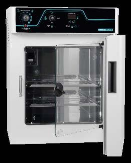
2 Pictured on cover: SMI6 SMI11 SMI12 (2 Stacked SMI6s) SMI2 SMI7 2 P age


3 SMI General Purpose Incubators Voltage Installation and Operation Manual Part Number: Revised: November 7, 2017 SHEL LAB is a brand of Sheldon Manufacturing, INC. Safety Certifications These units are CUE listed by TÜV SÜD as incubators for professional, industrial, or educational use where the preparation or testing of materials is done at an ambient air pressure range of inhg ( kpa) and no flammable, volatile, or combustible materials are being heated. These units have been tested to the following requirements: CAN/CSA C22.2 No :2012 CAN/CSA C22.2 No R:2009 UL 61010A-2-010:2002 UL :2012 EN :2010 EN : P age
4 TABLE OF CONTENTS INTRODUCTION... 5 Read this Manual... 5 Safety Considerations and Requirements... 5 Contacting Assistance... 6 Temperature Reference Sensor Device... 6 Engineering Improvements... 6 RECEIVING YOUR UNIT... 7 Inspect the Shipment... 7 Recording Data Plate Information... 8 INSTALLATION... 9 Installation Procedure Checklist... 9 Required Ambient Conditions Required Clearances Environmental Disruption Sources Power Source Requirements Lifting and Handling Leveling Install Incubator in Location Installation Cleaning Deionized and Distilled Water Install the Shelving Access Port GRAPHIC SYMBOLS CONTROL PANEL OVERVIEW OPERATION Theory of Operation Put the Incubator into Operation Set the Incubator Temperature Set Point Set the Over Temperature Limit Loading Samples Chamber Accessory Power Outlets Humidifying the Incubator Condensation and the Dew Point USER MAINTENANCE Cleaning and Disinfecting Minimizing Contamination Exposure Storing the Incubator...27 Door Components...27 Electrical Components...27 Calibrate the Temperature display UNIT SPECIFICATIONS Weight Dimensions Capacity Temperature Power PARTS LIST Ordering Parts and Consumables P age
5 INTRODUCTION Thank you for purchasing a SHEL LAB Incubator. We know you have many choices in today s competitive marketplace when it comes to constant temperature equipment. We appreciate you choosing ours. We stand behind our products and will be here for you if you need us. READ THIS MANUAL Failure to follow the guidelines and instructions in this user manual may create a protection impairment by disabling or interfering with the unit safety features. This can result in injury or death. Before using the unit, read the manual in its entirety to understand how to install, operate, and maintain the unit in a safe manner. Keep this manual available for use by all operators. Ensure all operators are given appropriate training before the unit begins service. SAFETY CONSIDERATIONS AND REQUIREMENTS Follow basic safety precautions, including all national laws, regulations, and local ordinances in your area regarding the use of this unit. If you have any questions about local requirements, please contact the appropriate agencies. SOPs Because of the range of potential applications, this unit can be used for, the operator or their supervisors must draw up a site-specific standard operating procedure (SOP) covering each application and associated safety guidelines. This SOP must be written and available to all operators in a language they understand. Intended Applications and Locations The incubators are intended for constant temperature, non-humidified general incubation applications in professional, industrial, and educational environments. The units are not intended for use at hazardous or household locations. Power Your unit and its recommended accessories are designed and tested to meet strict safety requirements. The unit is designed to connect to a power source using the specific power cord type shipped with the unit. Always plug the unit power cord into a protective earth grounded electrical outlet conforming to national and local electrical codes. If the unit is not grounded properly, parts such as knobs and controls can conduct electricity and cause serious injury. Do not bend the power cord excessively, step on it, or place heavy objects on it. A damaged cord can be a shock or fire hazard. Never use a power cord if it is damaged or altered in any way. Use only approved accessories. Do not modify system components. Any alterations or modifications to your unit can be dangerous and void your warranty. 5 P age
. EMAIL: support@sheldonmfg.")
6 INTRODUCTION CONTACTING ASSISTANCE Phone hours for Sheldon Technical Support are 6 am 4:30 pm Pacific Coast Time (west coast of the United States, UTC -8). Please have the following information ready when calling or ing Technical Support: the model number and the serial number (see page 8). support@sheldonmfg.com PHONE: extension 4, or (503) FAX: (503) Sheldon Manufacturing, INC. P.O. Box 627 Cornelius, OR TEMPERATURE REFERENCE SENSOR DEVICE This unit does not come with a temperature reference device. A reference device must be purchased separately for performing in-house accuracy validations or calibration adjustments of the incubator temperature display. The device must be accurate to at least 0.1 C and should be regularly calibrated by a third party. For best results, use a digital device with one or more thermocouple probes. Remote readings eliminate chamber door openings and avoid subsequent waits for the chamber temperature to re-stabilize. Select probes suitable for the application temperature you will validate or correct the display accuracy at. Alcohol thermometers are insufficient for conducting accurate validations and calibrations. Do not use a mercury thermometer. Never place a mercury thermometer in the incubation chamber. Always use thermocouple probes. ENGINEERING IMPROVEMENTS Sheldon Manufacturing continually improves all of its products. As a result, engineering changes and improvements are made from time to time. Therefore, some changes, modifications, and improvements may not be covered in this manual. If your unit s operating characteristics or appearance differs from those described in this manual, please contact your SHEL LAB dealer or customer service representative for assistance. 6 P age

7 RECEIVING YOUR UNIT INSPECT THE SHIPMENT When a unit leaves the factory, safe delivery becomes the responsibility of the carrier. Damage sustained during transit is not covered by the manufacturing defect warranty. Save the shipping carton until you are certain that the unit and its accessories function properly When you receive your unit, inspect it for concealed loss or damage to its interior and exterior. If you find any damage to the unit, follow the carrier s procedure for claiming damage or loss. 1. Carefully inspect the shipping carton for damage. 2. Report any damage to the carrier service that delivered the unit. 3. If the carton is not damaged, open the carton and remove the contents. 4. The unit should come with an Installation and Operation Manual. 5. Verify that the correct number of accessory items have been included. Included accessories Model Shelves Shelf Slides Leveling Feet Power Cord SMI2, SMI SMI SMI SMI Carefully check all packaging for accessories before discarding. 7 P age
8 RECEIVING YOUR UNIT RECORDING DATA PLATE INFORMATION The data plate contains the incubator model number and serial number. Tech Support will need this information during any support call. Record it below for future reference. The data plate is located on the top right corner of the incubation chamber door interior. Model Number Serial Number 8 P age
9 INSTALLATION INSTALLATION PROCEDURE CHECKLIST Carry out the procedures and steps listed below to install the incubator in a new workspace location and prepare it for use. All procedures are found in the Installation section of this manual. Pre-Installation Check that the required ambient condition for the unit are met, page 10 Check that the spacing clearance requirements are met, page 10 Unit dimensions may be found on page 33 Check for performance-disrupting heat and cold sources in the environment, page 10 Check that a suitable electrical outlet and power supply is present, page 11 Install the Incubator in a suitable workspace location Review the lifting and handling instructions, page 12 Make sure the incubator is level, page 12 Install the incubator in its workspace location, page 12 Set up the Incubator for use Clean and disinfect the unit and shelving (recommended), page 12 Install the shelving, page 13 Verify the port cover has been installed on the access port, page 13 9 P age
. Operating these units outside of these conditions may adversely affect its incubator temperature stability and effective operating range.")
10 INSTALLATION REQUIRED AMBIENT CONDITIONS These units are intended for use indoors, at room temperatures between 15 C and 30 C (59 F and 86 F), at no greater than 80% Relative Humidity (at 25 C / 77 F). Operating these units outside of these conditions may adversely affect its incubator temperature stability and effective operating range. For conditions outside of those listed above, please contact your SHEL LAB distributor to explore other options suited to your laboratory or production environment. REQUIRED CLEARANCES These clearances are required to provide air flows for ventilation and cooling. Power Cord 2 (51mm) 2 (51mm) Door Swing 4 (102mm) 4 (102mm) 4 (102mm) 4 inches (102mm) of clearance is required on the sides and back. SMI7 30 (762mm) All Other SMIs 26 (660mm) 2 inches (51mm) of headspace clearance between the top of the unit and any overhead partitions. ENVIRONMENTAL DISRUPTION SOURCES Consider proximate environmental factors that can affect the chamber temperature and atmospheric integrity when selecting a location to install the unit: Ovens, autoclaves, and any device that produces significant radiant heat High-traffic areas Direct sunlight Heating and cooling ducts, or other sources of fast-moving air currents 10 P age

11 INSTALLATION POWER SOURCE REQUIREMENTS When selecting a location for the unit, verify each of the following requirements is satisfied. Power Source: The power source for the unit must match the voltage and match or exceed the ampere requirements listed on the unit data plate. These units are intended for V 50/60 Hz applications at the following amperages: Model Amperage Model Amperage SMI2 4.5 Amps SMI7 6.5 Amps SMI6 6.0 Amps SMI11 7.0Amps Standard NEMA 5-15R wall socket The SMI12 requires comes with two power cords. It requires 6.0 amps for each cord. Supplied voltage must not vary more than 10% from the data plate rating. Damage to the unit may result if supplied voltage varies more than 10%. The wall power source must be protective earth grounded. Use a separate circuit to prevent loss of the unit due to overloading or circuit failure. The recommended wall circuit breakers for these units are 15 amps. The wall power source must conform to all national and local electrical codes. Power Cord: The unit must be positioned so that all end-users can quickly unplug the cord in the event of an emergency. Each unit comes provided with a 125 volt, 15 Amp, 9ft 5 in (2.86m) NEMA 5-15P power cord. Always use this cord or an identical replacement. Fuses: These units each ship with a fuse installed in the power cord inlet. The fuse must be installed and intact for the unit to operate. Always find and fix the cause of a blown fuse prior to putting the unit back into operation. Fuse types o o SMI7 and SMI11-250V T10 amp, 5x20mm SMI2, SMI6, SMI12-250V T6.3A, 5x20mm 11 P age


12 INSTALLATION LIFTING AND HANDLING The unit is heavy. Use appropriate lifting devices that are sufficiently rated for these loads. Follow these guidelines when lifting the unit. Lift the unit only from its bottom surface. Doors, handles, and knobs are not adequate for lifting or stabilization. Restrain the unit completely while lifting or transporting so it cannot tip. Remove all moving parts, such as shelves and trays, and lock doors in the closed position during transfers to prevent shifting and damage. LEVELING Install the 4 leveling feet with the 4 corner holes on the bottom of the unit. The unit must be level and stable for safe operation. Note: To prevent damage when moving the unit, turn all four leveling feet so that the leg of each foot sits inside the unit. INSTALL INCUBATOR IN LOCATION Install the unit in a workspace location that meets the criteria discussed in the previous entries of the Installation section. INSTALLATION CLEANING Cleaning and disinfecting the incubation chamber during installation reduces the chance of microbiological contamination. The unit was cleaned and disinfected at the factory. However, the unit may have been exposed to contaminants during shipping. Additionally, the factory procedure may not meet the standards of your institutional protocols. Please see the Cleaning and Disinfecting entry on page 25 in the User Maintenance section for information on how to clean and disinfect without damaging the chamber. Remove all wrappings and coverings from shelving prior to cleaning and installation. 12 P age

). 3. Push the slide into the horizontal slots. 4.")
13 INSTALLATION DEIONIZED AND DISTILLED WATER Do not use deionized water to clean or humidify the incubator. Use of deionized water may corrode metal surfaces and voids the warranty. The manufacturer recommends the use of distilled water in the resistance range of 50K Ohm/cm to 1M Ohm/cm, or a conductivity range of 20.0 us/cm to 1.0 us/cm, for cleaning and humidifying applications. INSTALL THE SHELVING To install the incubator shelves perform the following: 1. Hold the shelf slide at about a 10 angle. See figure 2A 2. Insert the hooked tab into the vertical slot at the desired height (Figure 2B)). 3. Push the slide into the horizontal slots. 4. Repeat for shelf slide at the same height on the opposite side of the incubator. 5. Place a shelf on the shelf slides. Repeat this procedure for additional shelves as needed. Shelving Installation ACCESS PORT SMI incubators are provided with a plastic cap for the access port on the right side of the incubation chamber. Always leave this cap in place, except when introducing sensor probes into the chamber, such as those used for temperature calibrations. Removing the cap during normal operations can adversely impact temperature stability and uniformity. 13 P age
14 INSTALLATION 14 P age

15 GRAPHIC SYMBOLS The unit is provided with multiple graphic symbols on its exterior. The symbols identify hazards and the functions of the adjustable components, as well as important notes in the user manual. Symbol Definition Consult the user manual. Consulter le manuel d'utilisation Temperature display Indique l'affichage de la température Over Temperature Limit system Thermostat température limite contrôle haute AC Power Repère le courant alternatif I/ON O/OFF I indique que l'interrupteur est en position marche. O indique que le commutateur est en position d'arrêt. Protective earth ground Terre électrique Indicates UP and DOWN respectively Touches de déplacements respectifs vers le HAUT et le BA Manually adjustable Indique un réglage manuel Recycle the unit. Do not dispose of in a landfill. Reycle l'unité. Ne jetez pas dans une décharge. 15 P age
16 GRAPHIC SYMBOLS 16 P age
17 CONTROL PANEL OVERVIEW Figure 1: Control Panel Over Temperature Limit Control (OTL) The Set Over Temperature dial sets the temperature limit at which the incubator cuts off heating in the incubation chamber. The red Over Temp Activated light illuminates when the OTL system is rerouting power away from the heating elements. For more details, please see the Over Temperature Limit System description in the Theory of Operations (page 19). Power Switch The power switch controls all power to each incubator and its systems. The green Power On light should illuminate when the switch is in the I (on) position. Temperature Control and Display During normal operations, the display shows the current incubator air temperature, accurate to 0.1 C. The Up and Down buttons are used to change display modes and then input either a new temperature set point or a calibration adjustment. The display blinks continually while in its set point or calibration adjustment modes, preceded by an SP for Set Point or C O for Calibration Offset. The Heating indicator light illuminates when the incubator powers the chamber heating elements. 17 P age
18 CONTROL PANEL OVERVIEW 18 P age
19 OPERATION THEORY OF OPERATION The SMI general purpose incubators are engineered to provide constant temperature incubation environments. Each unit can obtain a stable, uniform temperature in its chamber, ranging from the room temperature (ambient) +8 C up to 70 C for incubation applications. Each incubator features an inner glass viewing door that allows visual inspection of samples without compromising the chamber temperature environment. Each incubator unit in an SMI12 is independently powered and heated. Heating Each incubator is controlled by a microprocessor board with heating elements attached to the incubation chamber walls and a solid-state temperature sensor probe inside the chamber. The processor employs proportional-integral-derivative analytical feedback-loop functions when measuring and controlling the chamber air temperature. PID-controlled heating pulse intensities and lengths are proportional to the difference between the measured chamber temperature and the set point. The set point is the desired operating temperature entered by the user. The frequency of pulses is derived from the rate of change in the difference. The integral function slows the rate of pulses when the temperature nears the set point in order to prevent overshooting. The PID functions are also used to optimize incubator warming rates for hotter or cooler environments. Heat loss from leaving the incubator doors open for long periods of time (an hour or more) can trick the controller into operating as though in a cool environment. This can result in a period of temperature overshoots. Each incubator relies on natural heat radiation for cooling. An incubator can achieve a low-end temperature of the ambient room temperature +8 C. The fan inside in the incubator aids in maintaining air circulation and a uniform air temperature in the incubation space. The chamber door is self-heating to bolster the thermal uniformity and stability of the chamber and to minimize condensation on the glass viewing door. The glass door will cool while the chamber door is opening, eventually leading to condensate on the door and impacting the chamber temperature stability and uniformity. Minimize sample viewing times when possible. The Over Temperature Limit System The OTL is a mechanical heating cutoff included with each incubator and operates independently of the incubator microprocessor controller. The OTL helps safeguard samples by preventing runaway heating in the event of a hardware failure in the microprocessor controller or a sudden external heat spike. The OTL is connected to a hydrostatic sensor probe located inside the incubator and is intended to be set by the user to approximately 1 C above the current operating temperature set point. If the incubator temperature exceeds the OTL cutoff setting, the OTL will route power away from the incubator heating elements. It will continue to do so as long as the incubator air temperature is higher than the present OTL cutoff setting. A red indicator illuminates when the OTL is rerouting power. 19 P age


20 OPERATION PUT THE INCUBATOR INTO OPERATION Carry out the following steps and procedures to put the unit into operation after installing it in a new workspace environment Attach the power cord that came with the unit to the power inlet receptacle on the side of the incubator. Plug the power cord into the workspace electrical supply outlet. 3. Place the incubator Power Switch in the on ( I ) position. The Power light illuminates The Temperature display illuminates 4. Set the Temperature the Set Point to your incubation application temperature. See page Set the Over Temperature Limit. See page 22. The incubator must be heated and stable at your application temperature to perform this procedure. Allow the unit to run 8 hours (overnight) prior to: Loading Samples, page 23 Verifying the accuracy or calibrating the incubator temeprature display. End of procedure 20 P age


.")

21 OPERATION SET THE INCUBATOR TEMPERATURE SET POINT SMI12: Each incubator must be set independently. 1. Set the OTL control to its maximum setting, if not already set to max. Turning the OTL all the way to the right (clockwise) prevents the heating cutoff system from interfering with setting a higher temperature. 2. Jump to the Temperature Set Point Adjustment mode Set Temperature Set Temperature Set Point Adjustment Mode Initial Set Poiint Press and hold either Note: The display will automatically exit the adjustment mode after 5 seconds of inactivity on the arrow keys, saving the last shown set point value. 3. Set the Temperature Set Point Note: To turn an incubator off, set the set point to its lowest setting (OFF). New Set Point Adjust 4. Wait for 5 seconds after entering the Set Point Set Temperature HEATING ACTIVATED The display will stop flashing. The set point is now saved in the controller. The display will revert to showing the current chamber air temperature, heating or passively cooling to match the new set point. See the next page for how to set the Over Temperature Limit heating cutoff. End of procedure 21 P age
22 OPERATION Note: Test the OTL heating cutoff system at least once per year for functionality. SET THE OVER TEMPERATURE LIMIT The incubator must be operating at your incubation application temperature and must be stable for at least 1 hour prior to setting the OTL. Each incubator OTL must be set independently in the SMI Set OTL control to its maximum setting, if not already set to max. 2. Turn the dial counterclockwise until the red Over Temperature Limit Light illuminates. 3. Slowly turn the dial clockwise until the OTL Activated light turns off. The Over Temperature Limit is now set approximately 1 C above the current incubator air temperature. 4. Leave the OTL dial set just above the activation point. Optional: Turn the dial slightly to the left. This sets the OTL cutoff threshold nearer to the current incubator air temperature. If the OTL is sporadically activating, you may turn the dial slightly to the right (clockwise). If the OTL continues activating, check for ambient sources of heat or cold that may be adversely impacting the unit temperature stability. Check if any powered accessories in the workspace chamber are generating heat. If you can find no sources of external or internal temperature fluctuations, contact Tech Support or your distributor for assistance. End of Procedure 22 P age
 between sample containers and the chamber walls.")
23 OPERATION LOADING SAMPLES Place items on the shelves inside the incubation chamber as evenly spaced as possible. Proper spacing allows for maximum air circulation and a high degree of temperature uniformity. Leave 1 inch (2.5cm) between sample containers and the chamber walls. CHAMBER ACCESSORY POWER OUTLET These incubators are provided with an accessory outlet located inside the chamber, on the back wall. The power switch on the main control panel controls power to this outlet. The outlet is intended to power low-draw equipment such as magnetic stirrers or a volatile compounds scrubber fan. Do not attach equipment drawing more than 1 amp from the outlet. Waste Heat Accessory equipment may generate heat in the incubation chamber. This can affect the temperature performance of the incubator. HUMIDIFYING THE INCUBATOR Long-term use of a large water container, such as a humidifier pan, will create excess water vapor in the unit and can damage the electrical components of an SMI series dry incubator. Additionally, use of deionized water may cause significant corrosion damage to the incubator. Overloading the unit with sample media may also damage the incubator from excessive media evaporation and disruption of air flow pathways through the shelf space. Small Sample Load Placing a small number of petri dishes or other media containers in the incubator chamber may lead to excessively fast drying of sample media. A small water-filled container, such as an open flask, may be placed in the chamber to help slow sample drying with small loads. 23 P age
24 OPERATION CONDENSATION AND THE DEW POINT Condensation takes place whenever the humidity level in the incubator chamber reaches the dew point. The dew point is the level of humidity at which the air cannot hold more water vapor. The warmer the air, the more water vapor it can hold. As the level of humidity rises in an incubation chamber, condensate will first appear on surfaces that are cooler than the air temperature. Near the dew point, condensate forms on any item or exposed surface even slightly cooler than the air. When the dew point is reached, condensate forms on nearly all exposed surfaces. Ambient relative humidity humidity exceeding 80% or overloading the incubation chamber with open or breathable sample containers will likely result in condensation in the chamber, possible leaks around the incubator. This may cause corrosion damage if allowed to continue for any significant length of time. Managing condensation primarily depends on either lowering the humidity level or increasing the air temperature in the incubator chamber. Note: Note: Rising or falling air pressure from the weather will adjust the dew point up and down in small increments. If the relative humidity in the incubation chamber is already near the dew point, barometric fluctuations may push it across the dew threshold. Thin air at higher altitudes holds less humidity than the denser air found at or near sea level. If excessive condensate has appeared in the incubation chamber, dry the chamber interior and check the following. Check the door gaskets for damage, wear, or signs of brittleness or dryness. Arrange for replacement of the gaskets if damaged or excessively worn. Verify the chamber access port is closed. The black, plastic shipping cap that came with the unit should be installed on the outside of the incubator and not in the chamber. Make sure samples on the shelves are evenly spaced to allow for good airflow. Ensure the chamber door is closing and latching properly. Are frequent or lengthy chamber door openings causing significant temperature disruptions and chilling the chamber surfaces? If so, reduce the number of openings. Are there are too many open or breathable containers of evaporating sample media in the chamber? If so, reduce the number of open sample containers. Does the ambient humidity in the room exceed the stated operating range of 80% relative environmental humidity? If so, lower the room humidity. Is the incubator exposed to an external flow of cold air such as an air-conditioning vent or a door to a cooler hallway or adjacent room? Block or divert the air, or reposition the unit. 24 P age

25 USER MAINTENANCE Warning: Disconnect this unit from its power supply prior to performing maintenance or services. Avertissement: Débranchez cet appareil de son alimentation électrique avant d'effectuer la maintenance ou les services. CLEANING AND DISINFECTING If a hazardous material or substance has spilled in the unit chamber, immediately initiate your site Hazardous Material Spill Containment protocol. Contact your local Site Safety Officer and follow instructions per the site policy and procedures. Periodic cleaning and disinfection are required. Do not use spray on cleaners or disinfectants. These can leak through openings and coat electrical components. Consult with the manufacturer or their agent if you have any doubts about the compatibility of decontamination or cleaning agents with the parts of the equipment or with the material contained in it. Do not use cleaners or disinfectants that contain solvents capable of harming paint coatings or stainless steel surfaces. Do not use chlorine-based bleaches or abrasives; these will damage the chamber liner. Warning: Exercise caution if cleaning the unit with alcohol or flammable cleaners. Always allow the unit to cool down to room temperature prior to cleaning and make sure all cleaning agents have evaporated or otherwise been completely removed prior to putting the unit back into service. Avertissement: Soyez prudent lorsque vous nettoyez l'appareil avec de l'alcool ou des produits de nettoyage inflammables. Laissez toujours refroidir l'appareil à la température ambiante avant le nettoyage et assurez-vous que tous les produits de nettoyage se sont évaporés ou ont été complètement enlevés avant de remettre l'appareil en service. Cleaning 1. Disconnect the unit from its power supply. 2. Remove all removable interior components such as shelving and accessories. 3. Clean the unit with a mild soap and water solution, including all corners. o o o Do not use an abrasive cleaner, these will damage metal surfaces. Do not use deionized water to rinse or clean with! Take special care when cleaning around the temperature sensor probes in the chamber to prevent damage. Do not clean the probes. 4. Rinse with distilled water and wipe dry with a soft cloth. 25 P age
26 USER MAINTENANCE Disinfecting For maximum effectiveness, disinfection procedures are typically performed after cleaning. Keep the following points in mind when disinfecting the unit. Turn off and disconnect the unit to safeguard against electrical hazards. Disinfect the unit chamber using commercially available disinfectants that are non-corrosive, non-abrasive, and suitable for use on stainless steel and glass surfaces. Contact your local Site Safety Officer for detailed information on which disinfectants are compatible with your applications. If permitted by your protocol, remove all removable interior accessories (shelving and other non-attached items) from the chamber when disinfecting. Disinfect all surfaces in the chamber, making sure to thoroughly disinfect the corners. Exercise care to avoid damaging the sensor probes. When disinfecting external surfaces, use disinfectants that will not damage painted metal, glass, and plastic MINIMIZING CONTAMINATION EXPOSURE The following are suggestions for minimizing exposure of the incubator chamber to potential contaminants. Maintain a high air quality in the laboratory workspaces around the incubator. Avoid placing the incubator near sources of air movement such as doors, air vents, or high traffic routes in the workspace. Minimize the number of times the incubator chamber door is opened during normal operations. 26 P age
27 USER MAINTENANCE STORING THE INCUBATOR Perform the following steps if the incubator will be out of use for more than 24 hours to prevent microbiological contamination such as fungus or mold. 1. Depower the incubator. 2. Disinfect and clean if required by your laboratory protocol, or if the chamber has been exposed to pathogenic microorganisms. 3. Use a soft cloth to dry the chamber surfaces. DOOR COMPONENTS Periodically, inspect the door latch, trim, catch, and gaskets for signs of deterioration. Failure to maintain the integrity of the door system shortens the life span of the incubator. ELECTRICAL COMPONENTS Electrical components do not require maintenance. If the incubator fails to operate as specified, please contact your distributor or Technical Support for assistance. 27 P age


28 USER MAINTENANCE CALIBRATE THE TEMPERATURE DISPLAY Note: Performing a temperature display calibration requires a temperature reference device. Please see the Reference Sensor Device entry on page 6 for the device requirements. Note: Each SMI12 incubation chamber must be independently calibrated to its temperature display. Temperature calibrations are performed to match an incubator temperature display to the actual air temperature inside the incubation chamber. The actual air temperature is supplied by a calibrated reference device. Calibrations compensate for long-term drifts in the incubator microprocessor controller as well as those caused by the natural material evolution of the sensor probe in the heated incubator space. Calibrate as often as required by your laboratory or production protocol, or regulatory compliance schedule. Always calibrate to the standards and use the calibration setup required by your industry requirements or laboratory protocol. A suggested calibration setup 1. Introduce the reference device thermocouple sensor probes into the incubation chamber through the access port on the right side of the incubator. Heat-resistant non-stick tape recommended 2. Position the sensor probes in the incubation chamber with the probe heads at least at least 2 inches (51mmm) in diagonally from the chamber corners. The probe heads should be at least 2 inches (51mm) above the shelving to avoid heat sinking. Place 1 probe head as close as possible to the geometeric center point of the chamber. Secure all probes in place with non-stick, heatresistant tape. If using a only single thermocouple, place the sensor probe head as close as possible to the geometric center of the incubation chamber. 3. After securing the probe heads in position, carefully place the access port stopper in the port over the probe wires. Use non-stick tape to seal any gaps created between the stopper and the port by the probe wires. 2 (51m ) 4. The incubation chamber door must be closed and latched. Failure to do so will prevent an accurate calibration. 28 P age
29 USER MAINTENANCE 5) Temperature Stabilization The incubator air temperature must stabilize in order to perform an accurate calibration. Allow the incubator to operate undisturbed with the doors shut for at least 8 hours when first putting the unit into operation in a new environment. To be considered stabilized, the incubator chamber must operate at your calibration temperature for at least 1 hour with no fluctuations of ±0.1 C or greater. Begin Calibraiton Fluctuations (Exaggerated) Start Required temperature stabalization period operating undisturbed with the incubator door(s) closed. 1 Suggested Temperature Calibration Once the incubator temperature has stabilized, compare the reference device and incubator temperature display readings. If the readings are the same, or the difference between the two falls within the acceptable range of your protocol, the display is accurately showing the incubator air temperature. The Temperature Calibration procedure is now complete. - Or - Reference Device SET TEMPERATURE 2 If a difference falls outside of your protocol range, advance to step 2. Reference Device A display calibration adjustment must be entered to match the display to the reference device. See next step. Continued next page 29 P age


30 USER MAINTENANCE 3 Temperature Calibration Continued Place the display in its temperature calibration mode. a. Press and hold both the UP and DOWN temperature arrow buttons simultaneously for approximately 5 seconds. b. Release the buttons when the temperature display shows the letters C O. The display will begin flashing the current temperature display value. Note: If an arrow key is not pressed for five seconds, the display will cease flashing, and store the last displayed number as the new current chamber temperature value. 4 Reference Device Use the Up or Down arrows to adjust the current display temperature value until it matches the reference device temperature reading. 5 After matching the display to the reference device, wait 5 seconds. The temperature display will cease flashing and store the corrected chamber display value. The incubator will now begin heating or passively cooling in order to reach the set point with the corrected display value. Cooling to Set Point 6 After the incubator has achieved the corrected temperature, allow the chamber to sit at least one 1 hour undisturbed to stabilize. Failure to wait until the incubator is fully stabilized will result in an inaccurate reading. Set Point Achieved Continued next page 30 P age
31 USER MAINTENANCE 7 Compare the reference device reading with the chamber temperature display again. If the reference device and the chamber temperature display readings are the same or the difference falls within the range of your protocol, the incubator is now calibrated for temperature. Reference Device - OR - 8 See the next step if the readings fail to match or fall outside of your protocol range. If the two readings are not the same, and the difference still falls outside the acceptable range of your protocol, repeat steps 3 7 up to two more times. Three calibration attempts may be required to successfully calibrate units that are more than ±2 C out of calibration. Reference Device 9 If the temperature readings of the incubator temperature display and the reference device still fall outside your protocol after three calibration attempts, contact your incubator distributor or Technical Support for assistance. End of procedure 31 P age

32 USER MAINTENANCE 32 P age
33 UNIT SPECIFICATIONS These incubators are volt. Please refer to the incubator data plate for individual electrical specifications. Technical data specified applies to units with standard equipment at an ambient temperature of 25 C and at nominal voltage. The temperatures specified are determined in accordance to factory standard following DIN respecting the recommended wall clearances of 10 % of the height, width, and depth of the inner chamber. All indications are average values, typical for units produced in the series. We reserve the right to alter technical specifications at all times. WEIGHT Model Shipping Net Incubator Weight SMI2 117 lbs. / 53 kg 83.0 lbs. / 37.6 kg SMI6 183 lbs. / 83 kg lbs. / 71.7 kg SMI7 198 lbs. / 90 kg lbs. / 73.5 kg SMI lbs. / 136 kg lbs. / 88.5 kg SMI lbs. / 250 kg lbs. / kg DIMENSIONS In inches Model Exterior W D H Interior W D H SMI in in SMI in in SMI in in SMI in in SMI12* in in * Each chamber In millimeters Model Exterior W D H Interior W D H SMI mm mm SMI mm mm SMI mm mm SMI mm mm SMI12* mm mm * Each chamber 33 P age
34 UNIT SPECIFICATIONS CAPACITY Model Feet Liters SMI SMI SMI SMI SMI12* 11.7* 332.0* *Each chamber TEMPERATURE Model Range Uniformity Stability All Ambient +8 to 70 C 37 C ± C POWER Model AC Voltage Amperage SMI SMI SMI SMI SMI (6.0 each chamber) 34 P age


 NEMA 5-15P 1800510 Shelf Slide, SMI7 5081205 Shelf,")


35 PARTS LIST Description Parts Number Fuse, 6.3 Amp 250V, SMI2, SMI6, SMI Shelf, SMI6, SMI Fuse, 10 Amp 250V SMI7, SMI Shelf Slide, SMI6, SMI Leveling Foot Shelf, SMI Power Cord 115 volt 15 Amp, 9ft 5 in (2.86m) NEMA 5-15P Shelf Slide, SMI Shelf, SMI2 Shelf, SMI Shelf Slide, SMI2 Shelf Slide, SMI ORDERING PARTS AND CONSUMABLES If you have the Part Number for an item, you may order it directly from Sheldon Manufacturing by calling extension 3. If you are uncertain that you have the correct Part Number, or if you need that specific item, please contact Sheldon Technical Support for help at extension 4 or (503) Please have the model and serial number of the unit ready, as Tech Support will need this information to match your chamber with its correct part. 35 P age
36 P.O. Box 627 Cornelius, OR USA sheldonmanufacturing.com (503) FAX:
SMI INCUBATORS Voltage. Installation - Operation Manual
 SMI INCUBATORS 110 120 Voltage Installation - Operation Manual SMI31 SMI39 Pictured on Cover: SMI31 left, SMI39 right Manufacturing Warranty For information on your warranty and online warranty registration
FLY INCUBATORS Voltage. Installation - Operation Manual SRI6PF-2 SRI20PF-2
 FLY INCUBATORS 220-240 Voltage Installation - Operation Manual SRI6PF-2 SRI20PF-2 For Fly Cultivation This unit is designed for the growth, cultivation, incubation, and storage of fruit flies (Drosophila
FOV Series Forced Air Ovens Installation - Operation Manual
 FOV Series Forced Air Ovens Installation - Operation Manual TestEquity LLC 6100 Condor Drive Moorpark, CA 93021 Support: 877-512-3457, 805-480-0638 Corporate: 800-732-3457, 805-498-9933 http://www.testequity.com
BOD INCUBATOR Voltage. Installation - Operation Manual SRI20-2
 BOD INCUBATOR 220-240 Voltage Installation - Operation Manual SRI20-2 2 P age SRI20-2 BOD Incubator 220-240 Voltage Installation and Operation Manual Part Number (Manual): 4861787 Revision: November 10,
Forced Air Ovens 230 Voltage. Installation and Operation Manual SMO14-2, SMO28-2. Previously designated as FX14-2, FX28-2
 Forced Air Ovens 230 Voltage Installation and Operation Manual SMO14-2, SMO28-2 Previously designated as FX14-2, FX28-2 SMO Forced Air Ovens 230 Voltage Previously designated FX Forced Air Ovens Installation
ECONOMY GRAVITY OVENS Voltage. Installation - Operation Manual
 ECONOMY GRAVITY OVENS 110-120 Voltage Installation - Operation Manual SGO1E SGO6E 2 P age SGO Economy Gravity Ovens 110-120 Voltage Part Number (Manual): 4861566 Revision: December 5, 2017 Pictured on
INSTALLATION AND OPERATION MANUAL
 ECONOMY OVENS SMO1E SMO3E MODELS OBSOLETED AFTER MAY 31ST SMO1E-2, SMO3E-2, SMO5E, SOM5E-2 INSTALLATION AND OPERATION MANUAL Revised June 13, 2017 861659 Sheldon Manufacturing Inc. P.O. Box 627 Cornelius,
Vacuum Oven 230 Voltage. Installation and Operation Manual SVAC9-2. Previously designated as VPX9-2
 Vacuum Oven 230 Voltage Installation and Operation Manual SVAC9-2 Previously designated as VPX9-2 SVAC9-2 Vacuum Oven 230 Voltage Previously designated VPX9-2 Vacuum Oven Installation and Operation Manual
INCUBATORS MODELS: 1525, 1535, 1545, 1555, 1565 GENERAL PURPOSE INCUBATORS INSTALLATION AND OPERATION MANUAL
 INCUBATORS MODELS: 1525, 1535, 1545, 1555, 1565 GENERAL PURPOSE INCUBATORS INSTALLATION AND OPERATION MANUAL These units are UL listed general purpose air incubators for professional, industrial or educational
VACUUM OVEN. Model: VPX9-2. Installation and Operation Manual
 VACUUM OVEN Model: VPX9-2 Installation and Operation Manual Sheldon Manufacturing, Inc. P.O. Box 627, 300 N 26 th Avenue, Cornelius, Oregon 97113 EMAIL: tech @ Shellab.com; www.shellab.com 1-800-322-4897
BOD INCUBATORS MODELS: LI6P/LI6P-2 LI20P/LI20P-2 Installation and Operations Manual /12
 BOD INCUBATORS MODELS: LI6P/LI6P-2 LI20P/LI20P-2 Installation and Operations Manual 861666-1 05/12 Sheldon Manufacturing Inc. P.O. Box 627 Cornelius, Oregon 97113 EMAIL: tech@shellab.com INTERNET: http://www.shellab.com/~shellab
SMO FORCED AIR OVENS 230 Voltage. Installation - Operation Manual SMO14-2 SMO28-2 SMO28G-2
 SMO FORCED AIR OVENS 230 Voltage Installation - Operation Manual SMO14-2 SMO28-2 SMO28G-2 These ovens require permanent connect wiring (also known as a hardwiring) to a power source Pictured on Cover:
BEAD BATH. MODELS: , , & , , & V/ V Models INSTALLATION AND OPERATION MANUAL
 BEAD BATH MODELS: 74300-706, 74300-714, & 74300-720 74200-706, 74200-714, & 74200-720 100-120V/220-240V Models MICROPROCESSOR CONTROLLED INSTALLATION AND OPERATION MANUAL 4861685-1 03/12 These units are
VACUUM OVENS Volts. Installation - Operation Manual SVAC1-2 SVAC2-2 SVAC4-2
 VACUUM OVENS 220 240 Volts Installation - Operation Manual SVAC1-2 SVAC2-2 SVAC4-2 Pictured on cover left to right: SVAC1-2, SVAC2-2, SVAC4-2 The oven requires either a NEMA 6-15P electrical power outlet
MODEL: 1407, , 1408, & INSTALLATION AND INSTRUCTION MANUAL
 ECONOMY VACUUM OVEN MODEL: 1407, 1407-2, 1408, & 1408-2 INSTALLATION AND INSTRUCTION MANUAL Sheldon Manufacturing Inc. P.O. Box 627, Cornelius, Oregon 97113 EMAIL: tech@shellab.com INTERNET: http://www.shellab.com/~shellab
Vacuum Purge Ovens CVO-10. Installation - Operation Manual
 Vacuum Purge Ovens CVO-5 CVO-5-2 CVO-10 Installation - Operation Manual Vacuum Purge Ovens CVO-5: 110 120 Voltage North America CVO-5-2, CVO-10: 220 240 Voltage Part Number (Manual): 4861790 Revision:
Vacuum Oven 230 Voltage. Installation and Operation Manual SVAC9-2. Previously Designated: VPX9-2
 Vacuum Oven 230 Voltage Installation and Operation Manual SVAC9-2 Previously Designated: VPX9-2 SVAC9-2 Vacuum Oven 230 Voltage Installation and Operation Manual Part Number (Manual): 4861570 Revision:
1495D. Installation and Operation Manual, 230 Voltage 2/16/2017
 1495D Installation and Operation Manual, 230 Voltage 2/16/2017 VWR Vacuum Oven 230 Voltage (1495D) Installation and Operation Manual Part Number (Manual): 4861421 Revision: February 16, 2017 Ü CAN/CSA-C22.2
Artisan Technology Group is your source for quality new and certified-used/pre-owned equipment
 Artisan Technology Group is your source for quality new and certified-used/pre-owned equipment FAST SHIPPING AND DELIVERY TENS OF THOUSANDS OF IN-STOCK ITEMS EQUIPMENT DEMOS HUNDREDS OF MANUFACTURERS SUPPORTED
Clean Room Oven Voltage. Installation and Operation Manual SMO5CR-2
 Clean Room Oven 220 240 Voltage Installation and Operation Manual SMO5CR-2 2 P age SHEL LAB Clean Room Oven 220-240 Voltage Installation and Operation Manual Part Number (Manual): 4861580 Revision: November
INSTALLATION AND OPERATION MANUAL
 MICROPROCESSOR CONTROLLED OVEN MODELS: CE3F & CE5F 11/11 4861579 INSTALLATION AND OPERATION MANUAL Sheldon Manufacturing Inc. P.O. Box 627 Cornelius, Oregon 97113 EMAIL: tech@shellab.com INTERNET: http://www.shellab.com/~shellab
VACUUM OVENS MODEL: 1410MS,1430MS, 1450MS INSTALLATION AND OPERATIONAL MANUAL
 VACUUM OVENS MODEL: 1410MS,1430MS, 1450MS INSTALLATION AND OPERATIONAL MANUAL Sheldon Manufacturing Inc. P.O. Box 627 Cornelius, Oregon 97113 EMAIL: tech@shellab.com INTERNET: http://www.shellab.com/~shellab
VACUUM OVEN MODEL: 1425, 1445 & idealvac.com (505)
") idealvac.com (505)872-0037 idealvac.com VACUUM OVEN MODEL: 1425, 1445 & 1465 INSTALLATION AND OPERATION MANUAL Sheldon Manufacturing Inc. P.O. Box 627 Cornelius, Oregon 97113 EMAIL: tech@shellab.com INTERNET:
idealvac.com (505)872-0037 idealvac.com VACUUM OVEN MODEL: 1425, 1445 & 1465 INSTALLATION AND OPERATION MANUAL Sheldon Manufacturing Inc. P.O. Box 627 Cornelius, Oregon 97113 EMAIL: tech@shellab.com INTERNET:
Clean Room Oven Voltage. Installation and Operation Manual SMO5CR-2. Previously designated as CR1-2
 Clean Room Oven 220 240 Voltage Installation and Operation Manual SMO5CR-2 Previously designated as CR1-2 SHEL LAB Clean Room Oven 220-240 Voltage Installation and Operation Manual Part Number (Manual):
TTT Digital Incubator
 TTT Digital Incubator 135000 135000-2 Operating Instructions N2400342 Rev. 1 08/13 Table of Contents 1.0 Safety... 3 2.0 Intended Use of Product... 4 3.0 Installation... 4 3.1 Unpacking the Unit... 4 3.2
Artisan Technology Group is your source for quality new and certified-used/pre-owned equipment
 Artisan Technology Group is your source for quality new and certified-used/pre-owned equipment FAST SHIPPING AND DELIVERY TENS OF THOUSANDS OF IN-STOCK ITEMS EQUIPMENT DEMOS HUNDREDS OF MANUFACTURERS SUPPORTED
VACUUM OVEN MODEL: 1425, , , /
 VACUUM OVEN MODEL: 425, 425-2 445, 445-2 465, 465-2 INSTALLATION AND OPERATION MANUAL Sheldon Manufacturing Inc. P.O. Box 627 Cornelius, Oregon 973 EMAIL: tech@shellab.com INTERNET: http://www.shellab.com/~shellab
Bench Series Ovens Models 21 / 31 / 51 Operating Manual
 Heat cycle HEATER SWITCH RECIRC. FAN Quincy Lab, Inc. Bench Series Ovens Models 21 / 31 / 51 Operating Manual Standard Contents (1) Bench Series Oven (2) Adjustable chrome wire shelf (4) Shelf brackets
SHC10R-2 SHC28-2 SHC28R-2 INSTALLATION AND OPERATION INSTRUCTIONS SHC10R SHC28 SHC28R HUMIDITY CHAMBER. Revised March 19,
 HUMIDITY CHAMBER SHC10 SHC10R SHC28 SHC28R SHC10-2 SHC10R-2 SHC28-2 SHC28R-2 INSTALLATION AND OPERATION INSTRUCTIONS Revised March 19, 2018 4861578 Sheldon Manufacturing Inc. P.O. Box 627 Cornelius, Oregon
Supplemental Installation & Operation Manual. THE COLDWELL Stainless Steel Cold Trap
 Supplemental Installation & Operation Manual THE COLDWELL Stainless Steel Cold Trap For use with Labconco CentriVap cold traps KF25 Connections INTRODUCTION Locations and Applications Range This cold trap
Connection Instructions: Welch 2042 Vacuum Pump To TVO-2 Vacuum Oven
 Connection Instructions: Welch 2042 Vacuum Pump To TVO-2 Vacuum Oven 9990033 1 TABLE OF CONTENTS SECTION 1.0 SECTION 2.0 SECTION 3.0 SECTION 4.0 SECTION 5.0 SECTION 6.0 PRECAUTIONS SAFETY CONNECTION KIT
WATER BATHS. MODELS: SWBC22 and SWBC22-2 MICROPROCESSOR CONTROLLED INSTALLATION AND OPERATION MANUAL 12/
 WATER BATHS MODELS: SWBC22 and SWBC22-2 Previously designated as WPC65 & WPC65-2 MICROPROCESSOR CONTROLLED INSTALLATION AND OPERATION MANUAL 12/2013 4861565 These units are TUV CUE listed as water baths
INSTALLATION AND OPERATION MANUAL
 REACH-IN DRY CO 2 INCUBATOR SCO31 SCO31-2 SCO40 SCO41-2 PREVIOUSLY DESIGNATED AS 2428 2428-2 2440 2440-2 Revised 12/2013 4861504 INSTALLATION AND OPERATION MANUAL Sheldon Manufacturing Inc. P.O. Box 627
Package Contents. Dry Block Heater Power Cord Instruction manual Warranty Card. Serial Number: Date of Purchase: Supplier: Table of Contents
 - English... 1 Instruction Manual Analog, Dry Block Heater, 1 Block, HB1AL Analog, Dry Block Heater, 2 Block, HB2AL Analog, Dry Block Heater, 4 Block, HB4AL Analog, Dry Block Heater, 6 Block, HB6AL Digital,
VACUUM OVENS MODEL: , , INSTALLATION AND OPERATIONAL MANUAL
 VACUUM OVENS MODEL: 05012-80, 05012-85 05012-90, 05012-95 INSTALLATION AND OPERATIONAL MANUAL COLE-PARMER INSTRUMENT COMPANY 625 East Bunker Court, Vernon Hills, IL 60061 (847) 549-7600 FAX (847) 549-7676
Refrigerated Incubator Model and Operating Instructions
 Refrigerated Incubator Model 165000 and 165000-2 Operating Instructions N2400379 - Rev. 1 08May2018 1 Contents 1. SAFETY...3 1.1. EMF INTERFERENCE...4 1. PRODUCT INFORMATION...5 1.1 INTRODUCTION...5 2.
PR-L2466W- PA. Operating Instructions. High Performance Refrigerator PR-L2466W-PA
 Operating Instructions High Performance Refrigerator PR-L2466W- PA PR-L2466W-PA Please read these instructions carefully before using this product, and save this manual for future use. See page 11 for
HORIZONTAL AIR FLOW CLEAN ROOM OVEN
 HORIZONTAL AIR FLOW CLEAN ROOM OVEN MODEL: CR1-2 INSTALLATION AND OPERATIONAL MANUAL P.O. Box 627 300 N. 26 th Avenue Cornelius, Oregon 97113 EMAIL:tech @ Shellab.com INTERNET: http://www.shellab.com 1-800-322-4897
VACUUM OVEN SVAC1 SVAC1-2 SVAC2 SVAC2-2 SVAC4 SVAC4-2 Previously designated as 1425, , ,
 VACUUM OVEN SVAC SVAC-2 SVAC2 SVAC2-2 SVAC4 SVAC4-2 Previously designated as 425, 425-2 445, 445-2 465, 465-2 INSTALLATION AND OPERATION MANUAL Revised 3 / 206 48653 Sheldon Manufacturing Inc. P.O. Box
WATER BATHS MODELS: WPC95 & WPC95-2 INSTALLATION AND OPERATION MANUAL /12 MICROPROCESSOR CONTROLLED
 WATER BATHS MODELS: WPC95 & WPC95-2 MICROPROCESSOR CONTROLLED INSTALLATION AND OPERATION MANUAL 4861564 08/12 These units are TUV CUE listed as general purpose air incubators for professional, industrial
REFRIGERATED PREP TABLES Installation, Operation and Maintenance Instructions
 REFRIGERATED PREP TABLES Installation, Operation and Maintenance Instructions Please read this manual completely prior to installing and operating this equipment. This manual describes how to install,
Revolutionary Science RS-IF-202
 Instruction Manual for the Revolutionary Science RS-IF-202 Incufridge TABLE OF CONTENTS PAGES Recommended Safeguards 2 Introduction 3 Operating Instructions 4 Care and Maintenance 5 Specifications 5 Contact
Reacti-Therm I and III Heating Modules
 INSTRUCTIONS Reacti-Therm I and III Heating Modules TS-18822 TS-18824 Number TS-18822 TS-18824 Description Reacti-Therm I Heating Module (single block) Reacti-Therm III Heating Module (triple block) 2101.1
Reacti-Therm I and III Heating/Stirring Modules
 INSTRUCTIONS Reacti-Therm I and III Heating/Stirring Modules TS-18821 TS-18823 Number TS-18821 TS-18823 Description Reacti-Therm I Heating/Stirring Module (single block) Reacti-Therm III Heating/Stirring
Instruction Manual for the Revolutionary Science RS-IF-203 Incufridge
 Instruction Manual for the Revolutionary Science RS-IF-203 Incufridge REVOLUTIO NARY SCIENCE Manufacturer of Precision Laboratory Equipment Table of Contents Introduction 2 Recommended Safeguards 3 Operating
UNDERCOUNTER REFRIGERATORS AND FREEZERS Installation, Operation and Maintenance Instructions
 UNDERCOUNTER REFRIGERATORS AND FREEZERS Installation, Operation and Maintenance Instructions Please read this manual completely prior to installing and operating this equipment. This manual describes how
SPECIFICATIONS Power Requirements: V, 9.5A, 60Hz V, 5.8A, 50Hz Including 2A for internal convenience outlet.
 StableTemp Low Temperature Incubator Model 146E Catalog Number 39063-00(115VAC) 39063-05(230VAC StableTemp Low Temperature Incubator offers laboratories precise temperature control over the -10 C to 60
REACH-IN INCUBATOR MODEL: RI28/RI40 2/ INSTALLATION AND OPERATIONAL MANUAL
 REACH-IN INCUBATOR MODEL: RI28/RI40 2/13 4861573-1 INSTALLATION AND OPERATIONAL MANUAL Sheldon Manufacturing Inc. P.O. Box 627 Cornelius, Oregon 97113 EMAIL: tech@shellab.com INTERNET: http://www.shellab.com/~shellab
Revised 01/
 HUMIDITY CHAMBER SHC10 SHC10-2 SHC10R SHC10R-2 SHC28 SHC28-2 SHC28R SHC28R-2 PREVIOUSLY DESIGNATED AS : HC9 HC9-2/ HC9R HC9R-2 HC0 HC0-2 / HC0R HC0R-2 WITH MICRO PROCESSOR CONTROL INSTALLATION AND OPERATION
FS Series Forced Air Ovens. Operation and Service Manual
 FS Series Forced Air Ovens Operation and Service Manual TestEquity LLC 6100 Condor Drive Moorpark, CA 93021 Support: 877-512-3457 Toll Free 805-480-0638 Corporate: 800-732-3457 805-498-9933 http://www.testequity.com
BOD INCUBATORS MODELS: LI20 Installation And Operations Manual REV 05/
 BOD INCUBATORS MODELS: LI20 Installation And Operations Manual REV 05/12 4861576-1 Sheldon Manufacturing Inc. P.O. Box 627 Cornelius, Oregon 97113 EMAIL: tech@shellab.com INTERNET: http://www.shellab.com/~shellab
Operation Manual. (Version 1.5.1)
") VWR symphony TM Gravity Convection General Incubator Operation Manual (Version 1.5.1) VWR symphony Gravity Convection General Incubator 414004-610, 414004-612, 414004-614, 414004-616 414004-611, 414004-613,
VWR symphony TM Gravity Convection General Incubator Operation Manual (Version 1.5.1) VWR symphony Gravity Convection General Incubator 414004-610, 414004-612, 414004-614, 414004-616 414004-611, 414004-613,
Digital Heat Block User Manual
 Digital Heat Block User Manual Quidel Digital Heat Block Page 1 of 10 General Information Quidel Contact Information Contact Quidel Technical Support from 8:00 a.m. to 5:00 p.m. EST Tel: 800.874.1517 (in
Models: SSI5 SSI5-2 SSI5R SSI5R-2
 SSI5 SSI5-2 SSI5R SSI5R-2 Orbital Shaking Incubator Operational Manual Models: SSI5 SSI5-2 SSI5R SSI5R-2 Previously designated as SI6 SI6-2 SI6R SI6R-2 4861534 Revised: December 12, 2017 Table of Contents
INSTRUCTION MANUAL. UNDERCOUNTER WINE & BEVERAGE COOLER (32 bottles capacity) MODEL:WC-30U
 MODEL:WC-30U") INSTRUCTION MANUAL UNDERCOUNTER WINE & BEVERAGE COOLER (32 bottles capacity) MODEL:WC-30U To ensure proper use of this appliance and your safety, please read the following instructions completely before
INSTRUCTION MANUAL UNDERCOUNTER WINE & BEVERAGE COOLER (32 bottles capacity) MODEL:WC-30U To ensure proper use of this appliance and your safety, please read the following instructions completely before
G-10s. Instruction Manual. G-Series Cooler UPRIGHT COOLER. Part No.11IPA
 G-Series Cooler UPRIGHT COOLER Part No.11IPA-062800 Instruction Manual FOR YOUR FUTURE REFERENCE Thank you for using our product. This manual will guide you in getting the best use of your cooler. Remember
Ui REFRIGERATOR SPEC SHEET
 Ui REFRIGERATOR SPEC SHEET ISOMETRIC VIEW 19 7/8 20 1/2 32 3/4 FRONT VIEW NOTES: 1. CUTOUT DIMENSIONS: 20 1/2"W X 33"L X 20 3/4"D 2. CUTOUT DIMENSIONS ARE FOR REFRIGERATOR ONLY. REFER TO STAINLESS STEEL
Outdoor/Commercial Refrigerator USER S MANUAL
 Outdoor/Commercial Refrigerator USER S MANUAL MODEL Number:BLZ-SSRF40D IMPORTANT:READ THIS USER S MANUAL PRIOR TO CONNECTING POWER AND USE Before the refrigerator is used, it must be PROPERLY POSITIONED,
User Manual. Glass Countertop Mechandiser Refrigerator. Single Door Model: 360GSM3HCB, 360GSM3HCW Pass-Through Model: 360GSM32HCB, 360GSM32HCW
 Glass Countertop Mechandiser Refrigerator Single Door Model: 360GSM3HCB, 360GSM3HCW Pass-Through Model: 360GSM32HCB, 360GSM32HCW 12/2017 Please read the manual thoroughly prior to equipment set-up, operation
Outdoor Refrigerator USER S MANUAL
 Outdoor Refrigerator USER S MANUAL MODEL Number:BLZ-SSRF-40DH IMPORTANT:READ THIS USER S MANUAL PRIOR TO CONNECTING POWER AND USE Before the refrigerator is used, it must be PROPERLY POSITIONED, LEVELED
Narrow Depth Reach-in Refrigerator And Freezer Refrigerator model: 178A19RHC, 178A23RHC, 178A49RHC Freezer model: 178A19FHC, 178A23FHC, 178A49FHC
 Commercial Refrigerator And Freezer User s Manual Narrow Depth Reach-in Refrigerator And Freezer Refrigerator model: 178A19RHC, 178A23RHC, 178A49RHC Freezer model: 178A19FHC, 178A23FHC, 178A49FHC 10/2016
INSTRUCTION MANUAL. Model Number: DX K Wine Cooler BEFORE USE, PLEASE READ AND FOLLOW ALL SAFETY RULES AND OPERATING INSTRUCTIONS.
 INSTRUCTION MANUAL Model Number: DX-48.130K Wine Cooler CAUTION: BEFORE USE, PLEASE READ AND FOLLOW ALL SAFETY RULES AND OPERATING INSTRUCTIONS. TABLE OF CONTENTS 1. WINE COOLER SAFETY...114 2. IMPORTANT
MD-MINI Dry Bath. Instruction Manual
 MD-MINI Dry Bath Instruction Manual Catalog No. MD-MINI www.majorsci.com service@majorsci.com Version 01B Revision on: 2013.07.15 Packing list MD-MINI: 1x MD-MINI Dry Bath 1x MD-MINI Lid 1x Power Cord
ECONOMY OVENS MODELS: 1310, 1320, 1321F, 1324, 1325F, 1326, 1327F INSTALLATION AND OPERATION MANUAL
 ECONOMY OVENS MODELS: 1310, 1320, 1321F, 1324, 1325F, 1326, 1327F INSTALLATION AND OPERATION MANUAL Sheldon Manufacturing Inc. P.O. Box 627 Cornelius, Oregon 97113 EMAIL: tech@shellab.com INTERNET: http://www.shellab.com/~shellab
i-cube Microplate Incubator E10030
 i-cube Microplate Incubator E10030 User Guide and Operating Manual Table of Contents User / Owner Responsibility 3 Receiving 4 Warnings and Cautions 5-7 General Description 8 Specifications 9 Component
Installation and User's Manual for Refrigerator Model SCR33
 Installation and for Refrigerator Model SCR33 Introduction Congratulations on your purchase of a Scotsman refrigeration product. For future reference, keep this guide in a safe, accessible location. If
User s Manual Warm N Cozy
 User s Manual Warm N Cozy Point A Technologies, Inc. 20957 Currier Road, Unit C, Walnut, CA 91789 U.S.A. TABLE OF CONTENTS Page 1. Safety Procedures and Precautions...3 2. Electrical Information......4
DOUBLE DOOR COMPACT REFRIGERATOR. User Manual MODEL:KSTRC312BW KSTRC312BB
 DOUBLE DOOR COMPACT REFRIGERATOR User Manual MODEL:KSTRC312BW KSTRC312BB SERIAL/MODEL # S - IMPORTANT SAFETY INSTRUCTIONS Read and Save These Instructions This Owner s Guide provides specific operating
Instruction Manual. For All Corning Hot Plates, Stirrers, Stirrer/Hot Plates with Digital Displays, and External Temperature Controller (6795PR)
") Instruction Manual For All Corning Hot Plates, Stirrers, Stirrer/Hot Plates with Digital Displays, and External Temperature Controller (6795PR) Corning Cat. No. 230V 230V Model No. Product Top Plate Size
Instruction Manual For All Corning Hot Plates, Stirrers, Stirrer/Hot Plates with Digital Displays, and External Temperature Controller (6795PR) Corning Cat. No. 230V 230V Model No. Product Top Plate Size
WHYNTER Compressor Cooling Beverage Refrigerator - Stainless Steel
 WHYNTER Compressor Cooling Beverage Refrigerator - Stainless Steel Model Number: JC-88 MODEL# : BR-125SD Instruction Manual Thank you for your purchase of this WHYNTER product. Please read this Instruction
Instruction Manual. Model AccuPlate Hotplate AccuPlate Stirrers AccuPlate Hotplate Stirrer 12/10 CLS-EQ-LHP01REV
 Instruction Manual Model AccuPlate Hotplate AccuPlate Stirrers AccuPlate Hotplate Stirrer 12/10 CLS-EQ-LHP01REV2 9296050000 About This Manual This manual is designed to assist you in optimal usage of your
VWR Collection Model
 User Manual VWR Collection Model 89508-420 Refrigerated 6.1 cu ft Incubator Operating and Maintenance Manual 7003734 Rev. 0 Preface MANUAL NUMBER 7003734 0 -- 10/7/13 Original ccs REV ECR/ECN DATE DESCRIPTION
BULL INSTRUCTION MANUAL. Model Number: BC-130 REFRIGERATOR BEFORE USE, PLEASE READ AND FOLLOW ALL SAFETY RULES AND OPERATING INSTRUCTIONS.
 BULL INSTRUCTION MANUAL Model Number: BC-130 REFRIGERATOR BEFORE USE, PLEASE READ AND FOLLOW ALL SAFETY RULES AND OPERATING INSTRUCTIONS. 1 REFRIGERATOR SAFETY Your safety and the safety of others are
Wine Cellar. Instruction Booklet. Model: WC-2038
 Wine Cellar Instruction Booklet Model: WC-2038 IMPORTANT SAFEGUARDS Before the appliance is used, it must be properly positioned and installed as per the instruction in the Installation section. To reduce
Table of Contents. Specifications... page 2. Installation... page 3. Customizing... page 4. Reversing door swing... page 5
 Introduction The Scotsman Compact Refrigerator is a unique product, capable of being built into a cabinet because of its front vented, forced-air cooling system. It s also designed to be a companion to
Instruction Manual. Mini Hotplate Mini Stirrer Mini Hotplate Stirrer
 Instruction Manual Mini Hotplate Mini Stirrer Mini Hotplate Stirrer Table of Contents Package Contents............ 1 Warranty............ 1 Installation............ 2 Maintenance & Servicing............
G-7s. Instruction Manual. G-Series Cooler COUNTERTOP COOLER. Part No.11IPA
 G-Series Cooler COUNTERTOP COOLER Part No.11IPA-061000 Instruction Manual FOR YOUR FUTURE REFERENCE This easy-to-use manual will guide you in getting the best use of your cooler. Remember to record the
OPERATING INSTRUCTIONS. EchoThermJ ANALOG MULTI-POSITION STIRRERS AND STIRRING HOT PLATES. Document Number HS15-01 Revised May 20, 2011
 OPERATING INSTRUCTIONS EchoThermJ ANALOG MULTI-POSITION STIRRERS AND STIRRING HOT PLATES Document Number HS15-01 Revised May 20, 2011 Torrey Pines Scientific, Inc. 2713 Loker Ave. West Carlsbad, CA 92010
Water Boilers ME10EN, ME15EN. Table of Contents
 Water Boilers ME10EN, ME15EN Operator Manual Model ME15EN Model ME10EN Safety Information...2 Rough-In Drawing...3 Installation...4 Priming...5 Cleaning...5 Table of Contents Adjustments...6 Maintenance...7
LABORATORY OVENS MODELS INCLUDE: TO-152G & TOH-152G TO-152F & TO-235F DEHYDRATING OVENS MODELS INCLUDE: TD-150F TD-330F TD-500F
 0 LABORATORY OVENS MODELS INCLUDE: TO-152G & TOH-152G TO-152F & TO-235F DEHYDRATING OVENS MODELS INCLUDE: TD-150F TD-330F TD-500F WITH WEST 6100 CONTROL 1 IMPORTANT INFORMATION This manual contains operating
IQ/OQ Protocol Installation Qualification/ Operation Qualification zz FreeZone Stoppering Tray Dryer & Bulk Tray Dryer Freeze Dry Systems
 IQ/OQ Protocol Installation Qualification/ Operation Qualification zz FreeZone Tray Dryer & Bulk Freeze Dry Systems Labconco o: 1059501 Rev. - Purpose and Scope IQ and OQ This Qualification Protocol is
FR120RC/FR120RM FR120RR/FR120RB FN-153/FN-153C
 SAFETY WARNING (R-600a Models Only) This appliance contains a certain amount of isobutane refrigerant (R600a) a natural gas with high environmental compatibility that is, however, also combustible. when
WARNING/SAFETY PRECAUTIONS
 WARNING/SAFETY PRES To avoid any risk of personal injury, material damage or incorrect use of the appliance, be sure to observe the following safety precautions. (After reading these owner s instructions,
INSTRUCTION MANUAL (UNIT APPEARANCE MAY VARY FROM IMAGE) BEFORE USE, PLEASE READ AND FOLLOW ALL SAFETY RULES AND OPERATING INSTRUCTIONS.
 BEFORE USE, PLEASE READ AND FOLLOW ALL SAFETY RULES AND OPERATING INSTRUCTIONS.") INSTRUCTION MANUAL Model Number: FR551 REFRIGERATOR-FREEZER (UNIT APPEARANCE MAY VARY FROM IMAGE) BEFORE USE, PLEASE READ AND FOLLOW ALL SAFETY RULES AND OPERATING INSTRUCTIONS. Igloo has a policy of continuous
INSTRUCTION MANUAL Model Number: FR551 REFRIGERATOR-FREEZER (UNIT APPEARANCE MAY VARY FROM IMAGE) BEFORE USE, PLEASE READ AND FOLLOW ALL SAFETY RULES AND OPERATING INSTRUCTIONS. Igloo has a policy of continuous
Outdoor Beverage Center
 ON/OFF SET TEMPERATURE Outdoor Beverage Center Use and Care Guide Be sure unit is standing upright 24 hours prior to plug-in. Model: BBQ10715 IMPORTANT SAFEGUARDS Read all instructions before using this
REFRIGERATOR SAFETY. Your safety and the safety of others are very important.
 REFRIGERATOR SAFETY Your safety and the safety of others are very important. We have provided many important safety messages in this manual for your appliance. Always read and obey all safety messages.
Guide de l usager/user Guide
 Guide de l usager/user Guide ARR044R REFRIGÉRATEUR RETRO /RETRO REFRIGERATOR 4.4 PI CU/CU FT Pour une utilisation optimale de cet appareil ainsi que pour votre sécurité, veuillez lire attentivement les
BUILT-IN OVEN MODEL: EBO-D7080D(SS) Owner s Manual Please read this manual carefully before operating your set. Retain it for future reference.
 Owner s Manual Please read this manual carefully before operating your set. Retain it for future reference.") BUILT-IN OVEN MODEL: EBO-D7080D(SS) Owner s Manual Please read this manual carefully before operating your set. Retain it for future reference. Record model number and serial number of the set. See the
BUILT-IN OVEN MODEL: EBO-D7080D(SS) Owner s Manual Please read this manual carefully before operating your set. Retain it for future reference. Record model number and serial number of the set. See the
Use and Care Manual. Flammable Material Storage Refrigerator LRBFS06W1HC
 Use and Care Manual Flammable Material Storage Refrigerator LRBFS06W1HC 7085 471-00 Table of Contents Table of Contents Page Please Read and Follow these Instructions... 2 California Proposition 65...
HOUSEHOLD FREEZER 048-GM-48303/048-GM-48304/048-GM-48305
 HOUSEHOLD FREEZER 048-GM-48303/048-GM-48304/048-GM-48305 TABLE OF CONTENTS NAMES OF THE PARTS 2 IMPORTANT SAFETY INSTRUCTIONS 3 INSTALLATION INSTRUCTIONS BEFORE USING YOUR FREEZER. 3 INSTALLING YOUR FREEZER
Instruction Manual Mini Hotplate Mini Stirrer Mini Hotplate-Stirrer Mini Auto Stirrer Mini Fixed Temperature Hotplate
 Instruction Manual Mini Hotplate Mini Stirrer Mini Hotplate-Stirrer Mini Auto Stirrer Mini Fixed Temperature Hotplate Table of Contents Package Contents................ 1 Warranty................ 1 Installation................
INSTRUCTION MANUAL COMPRESSOR DRIVEN WINE COOLER
 INSTRUCTION MANUAL COMPRESSOR DRIVEN WINE COOLER DX-7.22SK DX-19.58SK DX-24.56BBK DX-24.56BSK DX-41.130BBK DX-41.130BSK DX-46.145BK DX-46.145SK DX-94.270DBK DX-94.270DSK DX-181.490DBK DX-181.490DSK This
PRE INSTALLATION PROCEDURES
 PRE INSTALLATION PROCEDURES DANGER! ELECTRICAL SHOCK HAZARD. Only qualified personnel who have read and understand this entire manual should attempt to install, or service this WL250 Water Treatment System,
Fisher Scientific Model 281A Vacuum Oven. Installation and Operating Manual Rev. 0
 Fisher Scientific Model 281A Vacuum Oven Installation and Operating Manual 30979 Rev. 0 Preface Models covered in this manual: Catalog numbers Models numbers Voltage 13-262-50 6288 120V 13-262-51 6289
OWNER S MANUAL ELECTRIC FLAT PANEL FIREPLACE. AC V 60Hz. Model# : /60 - Built-in & Wall Mounted Electric Fireplace WARNING CAUTION
 ELECTRIC FLAT PANEL FIREPLACE Model# :80017 OWNER S MANUAL 50/60 - Built-in & Wall Mounted Electric Fireplace AC 110-120V 60Hz WARNING Read and understand this entire owner s manual, including all safety
Installation & Operation Manual
 This SHEL LAB Product is Manufactured by Sheldon Manufacturing Inc. PO Box 627 Cornelius, OR 97113 Toll Free: (800)322-4897 Phone: (503)640-3000 Fax: (503)640-1366 email: tech@shellab.com web site: www.shellab.com
UPRIGHT FREEZER WHS-502FWEW1(E) WHS-502FWEB1(E) WHS-502FWESS1(E)
 WHS-502FWEB1(E) WHS-502FWESS1(E)") UPRIGHT FREEZER WHS-502FWEW1(E) WHS-502FWEB1(E) WHS-502FWESS1(E) TABLE OF CONTENTS NAMES OF THE PARTS.2 IMPORTANT SAFETY INSTRUCTIONS..3 INSTALLATION INSTRUCTION BEFORE USING YOUR FREEZER...3 INSTALLING
UPRIGHT FREEZER WHS-502FWEW1(E) WHS-502FWEB1(E) WHS-502FWESS1(E) TABLE OF CONTENTS NAMES OF THE PARTS.2 IMPORTANT SAFETY INSTRUCTIONS..3 INSTALLATION INSTRUCTION BEFORE USING YOUR FREEZER...3 INSTALLING
Installation & Operation Manual. AromaFlo. mr.steam. Feel Good Inc.
 Installation & Operation Manual AromaFlo Feel Good Inc. WARNING Risk of electric shock - This pump is supplied with a grounding conductor and grounding-type attachment plug. To reduce the risk of electric
Operator Manual Countertop Pizza Oven
 Operator Manual Countertop Pizza Oven PO18, PO18-220, PO22 Model PO-18 Table of Contents Safety Information...2 Specifications...3 Unpacking...4 Installation...4 Operation...4 Cleaning and Maintenance...5
Thermo Scientific Heratherm Microbiological Incubators. safe easy efficient
 Microbiological Incubators safe easy efficient Microbiological Incubators your samples We are obsessed with sample integrity. Each of our new microbiological incubators is designed with sample protection