INSTALLATION OPERATION SERVICE MANUAL
|
|
|
- Rosamund Polly McKinney
- 5 years ago
- Views:
Transcription
 251-2955 * Fax: (503)")
1 INSTALLATION OPERATION SERVICE MANUAL P.O. Box * Portland, Oregon Phone: (503) * Fax: (503) TOLL FREE: 1-800/ Website: detailplus@detailplus.com
2 THE CHEMSPENSE AUTO DETAILING SYSTEM Here s how it works A The CHEMSPENSE Work Stations are installed on each side of the vehicle to eliminate employee distraction. Everything needed to perform a variety of detailing services are at the attendant s fingertips. Chemical and air supply lines as well as electrical power are delivered to each CHEMSPENSE Work Station in overhead or underground lines. An internal Wet-Dry Vacuum and Heated Soil Extraction System provide 2 hoses for interior cleaning. (The system can also operate with a Central Vacuum System.) B C The Automatic Chemical Dilution & Dispensing System is installed in the equipment room, with the air compressor, pressure washer and other related equipment. 2


3 EQUIPMENT CHEMSPENSE WORK STATIONS: The CHEMSPENSE Work Stations should be located on both sides of the vehicle, servicing as distribution points for compressed air, vacuum, extractor, and various chemical products. Each line hangs easily by the applicator gun for easy access. Each Work Station is also equipped with a wet/dry vacuum and a heated soil extraction system complete with hoses, nozzles and hangers. Each Work Stations delivers 13 different chemical products. Each dispensing hose is equipped with a hand held control gun and an adjustable tip spray nozzle. The coiled chemical hoses are removed and replaced by simply hanging the gun on a bracket giving the Work Stations a neat appearance at all times. While the Work Stations themselves require no major maintenance, they should be cleaned regularly and inspected for leaks. 3
4
5
6 ASSEMBLY / WORK STATION Position the CHEMSPENSE Work Station appropriately in the bay and bolt to the floor. Attach left and right vacuum hose hangers; air line hangers; vacuum hose connector and vacuum exhaust ring. 6
7 ASSEMBLY / CHEMICAL HOSES CHEMICAL DISPENSING LINES (12): Place 3/8 male push fitting through hole in Work Station back panel under each line hanger. Place one washer and shut-off valve on inside and tighten. (DETAIL B) Now place coiled hoses on hangers and push securely into fitting. DETAIL B CHEMICAL & AIR TOOL LINES: The chemical and air lines hang from the Work Station. Install these lines as described above. NOZZLE HANGER ADJUSTABLE NOZZLE TIP QUICK DISCONNECT 7

8 (OldStyleTankUnits)
")
9 ( Ol dst yl etankuni t s) 9
10 ( Ol dst yl etankuni t s) 10
11 SUGGESTED ASSEMBLY / AIR LINES IN WORK STATION Bring the main air line into the Work Station using nylon tubing or threaded pipe. (For underground installations contact the factory for instructions.) Depending upon material used for air line install a T fitting on male air line in (Detail A) and run an air line to each elbow with shutoff. (Detail B)

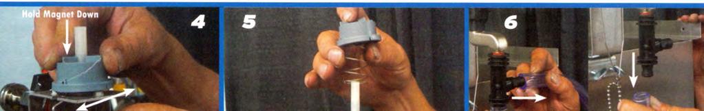
12 ASSEMBLY INTERNAL VACUUM MOTOR & TANK The Vacuum Motor and Tank are easily installed in the Work Station. Once the Work Station is in place and lines are connected, the electrical leads can be wired to the switches. (See wiring installation page.) Slip vacuum hose onto 1 ½ elbow on the side of the dispenser.
13 ASSEMBLY / ELECTRICAL The electrical requirements for the Work Stations are minimal. Run electrical conduit from the main box either overhead or underground to each Work Station. The electrical power is then connected to the vacuum on/off switches outlet boxes and hot water heater. Be sure to have the local electrician check that there are sufficient breakers in the electrical panel for each Work Station installed. WIRING DIAGRAM FOR 115 VOLT 60 HZ SINGLE PHASE INPUT POWER Notes: 1. Vacuum Motors should be grounded to metal enclosure. 2. The three 20 amp circuits can be brought in from the top or bottom. 3. All electrical wiring shall be installed in conformance with all applicable local electrical codes. 1
14 ASSEMBLY / ELECTRICAL WIRING DIAGRAM FOR 230 VOLT 50 HZ SINGLE PHASE INPUT POWER Notes: 1. Vacuum Motors should be grounded to metal enclosure. 2. The 230 volt circuits can be brought in from the top or bottom. 3. All electrical wiring shall be installed in conformance with all applicable local electrical codes. 1
15 ASSEMBLY / SOIL EXTRACTOR SYSTEM The CHEMSPENSE is available with a soil Extractor System for carpet & fabric upholstery that features: Heated Shampoo An electric in-line heater (over 190 F) One plastic recovery tank and filter Stainless steel extractor/vacuum nozzle A vacuum motor with 130 of water lift The vacuum motor, recovery tank and vacuum nozzle hanging bracket are to be installed exactly as the internal vacuum page. 1
16 INSTALLATION / EXTRACTOR SHAMPOO HEATER & CHEMICAL LINE The installation and plumbing of the extractor shampoo heater is quite simple. Run a 3/8 OD nylon tube from the chemical control manifold in the equipment room to the Work Station and bring into the unit from above or below and connect to the heater. 1
17 INSTALLATION / WORK STATIONS The installation of the CHEMSPENSE Work Stations will depend on the space available at each particular location. There are however, basic considerations that must be met in order to properly install the stations. WORK STATIONS: The Work Stations should be installed in the area between each bay. This area should be no less than 2 to 4 between bays. Note the recommended space ranges. If near a wall allow sufficient space (2-3 ) to have rear access to the Work Station. Bay depth: 25 to 30 Painted area: 08 to 20 Area between Bays: 02 to 04 Work Station Centers: 11 to 13 NOTE: Drive-through tandem bays would require different dispenser placement. Contact factor for assistance. SCALE 1
18 INSTALLATION / CHEMICAL LINES The installation of the chemical supply lines can be done either overhead or underground. OVERHEAD: If the lines are to be installed overhead you have a choice of materials: a) ½ Schedule 40 PVC Pipe b) 3/8 or 5/8 OD Solvent-Resistant It is recommended for the best installation to bolt the CHEMSPENSE Work Stations to the floor and then run chemical lines after the units are firmly in place. 1
19 OVERHEAD USING 3/8 OR 5/8 SOLVENT- RESISTENT TUBING THRU 6 PVC/ABS PIPES 4 or 6 PVC/ABS supported by hangers carry solvent-resistant tubing chemical lines 4 or 6 PVC/ABS branch lines carry solventresistant tubing into work stations. This schematic shows both work stations at rear or front of bays. This option uses solvent-resistant tubing that is run through 4 or 6 PVC pipe as illustrated. Depending upon the height of the ceiling PVC/ABS pipe can be hung directly from ceiling, support beams or suspended. A plastic push fitting tee is recommended to be used to bring the chemical supply lines into each CHEMSPENSE. 1

20 OVERHEAD USING 3/8 OR 5/8 SOLVENT- RESISTANT TUBING BUNDLED SOLVENT-RESISTANT TUBING This option uses solvent-resistant tubing that can be bundled together as illustrated and attached or suspended from the ceiling or overhead beams/supports. SEPARATELY SUPPORTED SOLVENT-RESISTANT TUBING A plastic push-fitting tee is recommended to be used to bring the chemical supply lines to each CHEMSPENSE
21 UNDERGROUND USING 3/8 OR 5/8 SOLVENT- RESISTANT TUBING & PVC/ABS PIPES If you are building a new detail facility you have the option of installing all supply lines underground chemical; air and electrical. If you choose this option, it is recommended to work directly with the DETAIL PLUS Technical Services Manager before beginning any work on the floor. Also, DETAIL PLUS must be advised of your decision to install supply lines underground in order to cut an opening in the bottom of the CHEMSPENSE (illustration B) As shown in illustration A, a minimum 4 PVC/ABS pipe must be run from the chemical Control unit to each CHEMSPENSE unit. It is recommended to work with the DETAIL PLUS technical services manager to layout the detail work bays equipment room with regard to underground pipes. ILLUSTRATION B

22 UNDERGROUND INSTALLATION (continued) For most trouble-free underground installation it is recommended that sets of 13 individual chemical lines be run from each CHEMSPENSE to the Chemical Dilution & Dispensing Unit in the equipment room.
23 INSTALLATION / CHEMICAL DILUTION & DISPENSING UNIT UNIT BASE Before mounting the nine (9) and six (6) gallon on pump racks to the wall you must connect a chemical line to each push fitting on the back side of the rack. Then run this line out of the holes on the top right side of the rack. Note: Leave at least 5 to 6 of tubing out of the hole. Now you can mount the unit base and pump racks. Install the base of the chemical dispensing unit against the wall and secure, if desired. Next mount the six (6) pump rack at least 6 above the base. Then mount the one (1) gallon holding tray above that. Finally, mount the nine (9) pump rack 6 to 8 above the one (1) gallon holding tray. With the Chemical Dilution and Dispensing System mounted, you must now run six 4 foot pieces of 3/8 tubing through the remaining six holes in the top right side of the nine (9) pump rack. To meet with the six chemical lines that run from rear of the six (6) pump rack. Using a 3/8 union join these lines together. The Chemical Dilution and Dispensing System is now ready for you to run the lines to each dispenser. 2


24 INSTALLATION / CHEMICAL DILUTION & DISPENSING UNIT 2
25 INSTALLATION / AIR LINES & TROUBLE SHOOTING The plumbing of your air distribution system is critical to a trouble-free operating system. OVERHEAD: If your installation is overhead the main line should be looped around the entire shop area (see illustration) and connected back to the starting point. This allows the air to flow in two directions, toward the point of greatest use and essentially doubles the air systems flow capacity. The size of the main line from the compressor to the furthest point in the shop should be 1 for runs of 50 or less, and 1 ½ for longer runs. Drop lines into the CHEMSPENSE should be ½. UNDERGROUND: It is recommended to discuss with the DETAIL PLUS Factory how to do an underground air line installation. HUMIDITY IN LINES: When a compressor squeezes air it also compacts the humidity in the air. As the air in the line cools, the humidity condenses and water collects in the pipes. Therefore, the Main Line and Drop Lines must be off horizontal with the high and low points throughout the shop to force the water to drain away from the Work Stations and back to the strategically located drains (see drawing). NOTE: The tee off the Main Line to the drain should be turned down in order for the water in the lines to drain out. 2
26 INSTALLATION / AIR LINES & TROUBLE SHOOTING (Continued) But, when installing the Drop Lines into the Work Stations the tee off the Main Line should be turned up to avoid line water from draining into air lines on the Work Stations. The loop system described will create constant air motion and cause accumulation of oil, water scale and other pipeline contaminants to collect at multiple low points. Failure to install lines properly with optional beltguard aftercoolers and moisture separators as specified will allow water to condense in the air lines. If allowed to reach the pneumatic tools, this water will cause rusting and eventual damage to the tools. PROPER VENTILATION: Compressors are air cooled and can easily overheat if proper ventilation is not provided. Cool air should be available for the compressor s flywheel fan and rejected away from the general area. Closed room or restricting barriers will shorten the life or make the compressor inoperable. Be sure that compressors are at least 18 from a solid wall to prevent overheating. Two machines installed close together can reject heat on each other or share inadequate cooling air. Each machine must be considered separately for proper cooling. Ideally, each unit would face an outside wall with cooling air ventilators adjacent to the flywheel fans. The heated air would then be directed to an unobstructed area without return circulation. Forced air exhausts and or vents may be required. Outside installations are discouraged unless available when needed. TWO COMPRESSOR OR *DUPLEX SYSTEM OPERATION: Designate two compressors as 1 and 2. Number 1 should be designated as the lead unit and adjusted to operate ON at 125 psig and OFF at 150 psig. Number 2 is the lag unit and should be adjusted to cut in at 120 psig and off at 145 psig. Number 1 will carry the basic load until more air us used than it can supply. As the system pressure falls below 125 psig, Number 2 standby kicks in and both units fill the pipelines. As the recovery continues and 145 psig is reached, the standby Number 2 cuts out. If Number 1 can carry the load the pressure will continue to build and its cut out pressure of 150 psig will be reached and both machines will shut off. The sequence will repeat. Setting pressure correctly without over pressurizing saves leaks, energy, maintenance and more. When a compressor will not operate mechanically, do not attempt to repair. Call a qualified technician! This section will deal only with common system complaints and minor operational problems. *DUPLEX one large tank on which two compressor motors are mounted. 2
27 TROUBLESHOOTING COMPLAINT #1 Moisture in the air lines: This is a direct result of intake air relative humidity and is not caused or created by the air compressor. The amount of moisture in the air lines is related to the surrounding humidity or lack of humidity at any one time. Since you have no control over outside humidity, the following remedies will help: a. Locate compressors in a cool dry environment. b. Keep units clean, especially the tank surface. c. Add forced ventilation if necessary to keep area temperature at or close to average shop temperature. d. Drain tank daily or more often when needed. e. Add aftercoolers to sufficiently lower the compressed air temperature whereby the dew point is quickly reached and moisture is condensed in the tank rather than down stream. (Aftercoolers create rain in the tank.) f. Refrigerated air dryers are the final solution and literally freeze-dry the air. Wayne and LeRoi dryers are specially designed to optimize efficiency and reliability. They are the standard for the industry. Contact your representative for models easy to size, install and operate. g. Follow the main line loop and drain leg recommendations on the Air Distribution System Page. COMPLAINT #2 Oil, rust and other contaminates in the air lines: This situation is directly related to Complaint #1 and would be resolved the same way. However, a filter-separator mounted on the tank(s) outlet would add extra back-up and is available with visible bowls and auto dumps. Water vapor will pass through a separator in a gaseous form whereby oil and scale will be separated. COMPLAINT #3 System air pressure drops below normal during peaking hours. If only one machine is available, then it should be duplicated for a 100% back up. Set the machine pressures as previously indicated for lead-lag operation. If two compressors are being used, both should be replaced with the next larger models, i.e., replace two 5 HP s with two 7 ½ HP units. Also, a check should be made to establish if the air loss is through leaks. A quick check is to stop using air and time the compressor on-off cycles; run time equals leaks. 2

28 (OPTIONAL) INSTALLATION / CENTRAL VACUUM LINE The Central Vacuum Manifold should be constructed of 4, 3 and 2 PVC Pipe appropriate tees and elbows. For each 1 ½ drop into the Work Stations use 1 ½ PVC. For easy cleanout put tees at each end of the main manifold and on each 1 ½ drop. To insure maximum pressure, divide the total distance of the main manifold by three and place 4, 3 and 2 sections starting with 4 closest to the Central Vacuum. *It is recommended that a moisture separator be installed with the Central Vacuum. 2
29 START-UP PROCEDURES PRESSURE TESTING: Before running any chemicals through the system it is essential to pressure test the entire system with water for possible leaks in the chemical lines and connections. Start by filling a container with water. Then adjust each individual pump regulator to the recommended pressure for that chemical solution. (See page 26) Next check all the chemical lines from Chemical Control Unit to each Work Station. Check all connections on the Control Unit; all connections on the Work Stations; finally all coiled hoses and application valves. Repair leaks as required. It is then ready to place chemicals in the system. CLEANING SYSTEM: After the system has been pressure tested and leaks repaired, it is STRONGLY RECOMMENDED that you clean out the entire system by flushing it with water, Work Station by Work Station. This will remove any small particles of dirt or plastic fillings that can invade the application valves and cause them to leak. The cleaning is accomplished by refilling chemical containers with any water that was lost from the leaks. Next, turn off the shut-off valves on every Work Station. Starting with the Work Station furthest away from the Chemical Control Unit, remove all chemical application guns from the coiled hoses and place ends in a large container. Next, turn on each shut-off valve and let the water run for at least one minute. Turn off the shut-off valves, replace the application guns. Move to the next Work Station and repeat the procedure until all lines have been cleaned. It will be necessary to periodically refill the containers with water to complete the flushing process. CHECKING APPLICATION GUNS: After the cleaning and flushing process it is recommended to check each application valve for any leaks. To do this, insure there is sufficient water in the tanks. Next, turn on the shut-off valves on each Work Station. NOTE: Climate and temperature in the Equipment Room and Work Bays can effect the viscosity of some thicker chemicals and may require higher pressures at different times. 2
30 START-UP PROCEDURES (Continued) RECOMMENDED PUMP PRESSURES 2000 Grit ONE STEP psi Fine Finish Plus psi MINK PLUS psi Deodorizer psi Swirl/Away Polish psi DIAMOND PLUS Sealant psi Extractor Shampoo psi Glass Cleaner psi Dressing psi Fabric Protectant psi Tar & Grease Remover psi Carpet & Upholstery Shampoo psi THE WET/DRY VACUUM: Every CHEMSPENSE Work Station is equipped with one vacuum hose and nozzle and one extractor hose and nozzle. The hose outlets are on the side of the CHEMSPENSE Work Stations. The vacuum is used to dry vacuum the vehicle interior and to aid in the removal of residual moisture from carpets and upholstery after shampooing and extracting. NOTE: When not using a vacuum hose be sure to always hang up. Vacuum on/off switches are located on each side of the CHEMSPENSE, but are not 2-way switches. So, when turned on the right side it must be shut off on the right side. VACUUM EXHAUST OUTLET: Each CHEMSPENSE has a vacuum exhaust outlet on each side of the unit. MAINTAINING THE WET/DRY VACUUM: The CHEMSPENSE Vacuum System is nearly maintenance free. Vacuum hoses should be periodically checked for clogging, especially if you are experiencing a reduction of suction.
31 START-UP PROCEDURES (Continued) Vacuum filters should be cleaned every 2 to 3 days, at a minimum. Simply remove it and rinse it out with water and be sure to properly replace it. Without the filter large particles can get into and ruin the vacuum motor. The Recovery Tank should be dumped out and washed out every night. THE SOIL EXTRACTION SYSTEM: The CHEMSPENSE Soil Extraction System is unique in that there is one unit in each CHEMSPENSE and the operator does not have to refill the solution tank. PURGING THE CHEMICAL LINES: It is possible that from lack of use or use of compounds; polishes and waxes/sealants that separate, your chemical lines can become clogged. If that happens you need to quickly remove the clog and get the chemicals flowing again. Clogging can occur in two areas: a. Coiled hose on the CHEMSPENSE b. Main feeder line of Chemical Supply Center Coiled Hose - Many times the clogging may be in the gun rather than the coiled chemical hose. Therefore, if you find a particular line is clogged be sure to check the gun first. Turn off the valve in the rear of the CHEMSPENSE and then remove the applicator gun and clean it out. It may require taking the gun apart and cleaning all internal parts and reassembling. Should the line be clogged what you must do is disconnect the coiled hose from the CHEMSPENSE and remove the applicator gun and put the tip of an air gun in the end of the hose and try to force air through the line to remove the clogged chemical. If you are unable to remove the chemical using this method it may be easier to simply replace the line. Main Feeder Line - If the main feeder line from the Chemical Supply Center is clogged you can try two methods to unclog the line: a. Disconnect the main line that connects to the angle valve on the rear of the CHEMSPENSE and put an air blower into the end of the line and try to force the clogged chemical back into the container. b. If this does not work you will need to fill a container with the hottest water you can and obtain and pump it through the system at the highest pressure the pump will put out. If this does not work, it may be necessary to replace the entire line. NOTE: Clogged lines occur for only two reasons, (a) Lack of use of the chemical lines or, (b) use of compounds, polishes and waxes that separate when sitting. Clogged lines can be prevented very easily, (a) Every day be sure all the lines with these chemicals in them are opened and flowing and, (b) use chemicals that DO NOT SEPARATE
32 TROUBLESHOOTING LEAKS: As with any system using air, the chemical distribution lines or fitting could develop leaks. These leaks can usually be repaired by tightening a fitting, replacing a fitting, or replacing a hose. CLOGGED LINES: Occasionally, some of the thicker chemicals may clog in the distribution lines from lack of use. These clogs can usually be removed by blowing compressed air back through the line, or flushing with hot water. Periodic purging (as described) of the system will reduce the chance of clogging. CHEMICAL APPLICATOR GUNS: The hand held application guns can occasionally become clogged. This can easily be remedied by closing the shut-off valve in the rear of the Work Station, removing the gun and cleaning it. Unscrew the cap and nozzle on the gun, and blow air or water into the end. Unscrew the handle and blow air or water into that opening. Should these procedures not work contact the factory for rebuilding instructions. COILED CHEMICAL & AIR HOSES: While these hoses are rated for 25, it is recommended that you do not extend them beyond 20 in order to obtain maximum life. If a leak occurs in the hose near the end. It is recommended that you simply cut off and replace the fitting. If the leak occurs in the middle of the hose, it is better to immediately replace the entire coil. REMEMBER: INSTRUCT EMPLOYEES NOT TO EXTEND THE HOSES BEYOND 20.
33 HOW TO OPERATE & USE THE CHEMSPENSE WORK The operating principle of the CHEMSPENSE Work Station is to put everything needed to detail a vehicle at the attendant s fingertips. Chemicals, air lines, wet/dry vacuum and soil extractor are at arm s length from the vehicle. This eliminates the need for employees to leave their work area, common in most squeeze and spray bottle detail shops. CHEMICAL LINES: The coiled chemical lines are easily accessible. Product lines for interior cleaning chemicals can be taken into the vehicle interior or trunk and replaced after use. Chemical lines for the compounds, polishes and waxes are used several times during the paint finishing process. Therefore it is recommended that after the line is initially taken off the CHEMSPENSE unit that it be placed in the refuse bin on the Portable Detail Work Cart. This allows you to move it with you down the vehicle by simply pushing the cart. AIR LINES: The air lines are used to power pneumatic tools with an Air Chuck to blow water out of cracks in the car or to clean interiors. When using with an air tool you can lay the tool, when not in use on the Portable Detail Work Cart. NOTE: Always hang up the coiled lines after use. This will prevent time consuming tangling of the lines. The System utilizes the same motor and recovery tank as the Wet/Dry Vacuum. The Extractor System includes a single phase heater that heats the extractor shampoo to 200 degrees Fahrenheit for maximum cleaning. Each CHEMSPENSE is equipped with one extractor vacuum hide-a-hose solution line with a special stainless steel nozzle with a view window. 3
34 HOW TO OPERATE & USE THE CHEMSPENSE WORK (Continued) OPERATING THE EXTRACTOR SYSTEM: Carpet and fabric upholstery cleaning can involve a variety of steps or methods, as follows: Method 1 For extremely dirty carpets and upholstery you utilize the following steps: 1. Vacuum thoroughly all dry soil. 2. Spot heavy stains and remove by hand methods. 3. Pre-spray with carpet shampoo, let dwell. 4. Friction shampoo by hand or rotary shampooer, or both as necessary. 5. Extract with heated shampoo solution until all dirt and shampoo residue is removed. 6. Re-vacuum as needed. Method 2 For slightly dirty carpets and upholstery follow these steps: 1. Vacuum 2. Spot stains and remove 3. Extract with heated shampoo solution until dirt is removed 4. Re-vacuum as needed After determining which extraction method you will use turn on the vacuum switch. Begin the extraction process by pressing the valve and move the nozzle slowly across the carpet or upholstery toward the operator in straight motions. Do no move the extractor nozzle back and forth while fluid is being dispensed. This will over wet the carpet or fabric with too much solution. HOT SHAMPOO EXTRACTION: When using the hot shampoo extractor, keep in mind the solution in the lines could be cold requiring you to bleed the lines before beginning extraction. Excess chemical can be sprayed onto floor mats or carpets for added cleaning action. MAINTAINING THE EXTRACTOR SYSTEM: Periodically check the chemical application valves for any leaks. The tank filter cover should be cleaned daily when the recovery tank is emptied. Periodically check the heater inlets and outlets for leaks. 3
35 HOW TO OPERATE & USE THE CHEMSPENSE WORK (Continued) Note: You must run flush the heaters with an acid rinse at least once per month if the water is soft (no minerals). If the water source is hard (highly mineralized) you should flush the system every 2 weeks, or more to insure heater channels do not clog. If this is not done warranty will be voided. Mix one cup of acidic rinse with one gallon of water and run approximately one gallon of solution through each in-line heater. 3
36 CHEMSPENSE COMPONENTS PARTS LIST 3
37 3
38 3
39 3
40
41


42


43 4
44 INSTALLATION OF THE WASH BAY CHEMICAL CONTROL UNIT 4

45 45
46 INSTALLATION WASH BAY CHEMICAL LINE HANGERS The stainless steel wall-mounted chemical line hangers should always be mounted above head height (6 or more) to avoid any injuries to employees. Assembly of the chemical line hanger is quite simple. Follow instructions in illustrations A & B. For a single wash bay a chemical line hanger should be installed on each side of the bay for easy access. For a double bay setup 3 hangers are provided, one for the left, right and one for the middle. ILLUSTRATION A 4
47 INSTALLATION OF PRESSURE WASH SYSTEM & HOSE BOOMS 4

48 ON-DEMAND PRESSURE WASHER ON-DEMAND PRESSURE WASHER: NOTE: Before operating the On-Demand Pressure Washer, double check to be sure the system has been wired and plumbed correctly. If there is any questions, please consult with DETAIL PLUS before operating. Next, read all factory catalogs on the High Pressure Pump and electric motor. If this information is not available, please contact DETAIL PLUS. Factory catalogs will provide maintenance and lubrication information. SPECIFICATIONS DUAL UNIT Motor 7 ½ HP, 3 phase electric motor 50/60 HZ any voltage. Pump Hydro 2414 B-P 8GPM at 1000 PSI at each gun. SPECIFICATIONS SINGLE UNIT Motor 3 HP 3 phase electric motor 50/60 HZ any voltage. Pump Cat pump 3CP GPM 1000 PSI. 4
49 ON-DEMAND PRESSURE WASHER (CONTINUED) The DETAIL PLUS On-Demand Pressure Washer system is unique in that it requires no on/off switches for operation. All the operator has to do is pull the trigger on the pressure gun and the systems turn off. The secret to the On-Demand System are two valves (switches) the Flow Switch and the Temperature Safety Switch. The Flow Switch is to be wired so that one leg of the coil voltage runs through the Flow Switch (use 24 vac coil voltage for safety). The same leg that is looped through the Flow Switch must also be looped through the Temperature Safety Switch (this is pre-wired at the factory). HOW ON-DEMAND WORKS: When the pressure gun is opened, the water flows through the Flow Switch (normally open). The switch then closes completing the electrical circuit to the starter coil which turns on the pressure washer. When the pressure gun is closed the flow of water is stopped and the pressure washer turns off automatically. TEMPERATURE SAFETY SWITCH: This is normally-close which is also looped through the starting circuit as a safety backup for the Flow Switch. For example, if the Flow Switch becomes inoperable, the pressure washer would continue to run even with the pressure gun closed. If this is allowed to continue the pump could be severely damaged. The Temperature Safety Switch will prevent this from occurring. If the pump temperature rises above 145 F the Switch will open, shutting off the pressure washer before any permanent damage can occur. When the operator opens the gun, cool water will enter the system, closing the Temperature Safety Switch allowing the pressure washer to operate again. This switch is provided for safety only to prevent damage to the pump. NOTE: The Flow Switch must be replaced immediately to prevent any damage to pump. If the Flow Switch is completely inoperable, the pressure washer should be turned off manually when not in use to prevent overheating and pump damage. This will prevent the pressure washer from starting when the temperature drops below 145 F while not in use. 4
50 ON-DEMAND PRESSURE WASHER (CONTINUED) Recommended Items for Pressure Wash Installation 1. Enclosure size & style will vary depending on installation conditions, starter size and style. 2. Motor Starter w/24 VAC coil & overload. 7.5HP 230/ /9.1 Full Load Amps Dual 30HP 230/ /3.8 Full Load Amps Single 3. Power Transformer please use a transformer that is larger than the MA for the starter coil. This is due to the fact we experience problems with the Reed Switch inside the Flow Control Switch sticking on systems where the transformer is close to the MA rating of the coils. 4. Cam Switch be maintained ON-OFF-ON. For this use it will be AUTO-OFF-MANUAL and will need two (2) separate contact blocks. The Flow control and Fluid Temperature Safety Limit are installed on the pressure washer unit. The Temperature Limit Switch only disrupts the coil voltage and will restart the system automatically when the fluid temperature drops below 145 F. Care should be taken to guard against accidental starting. A relay could be added to force a restart of the system. NOTE: This system(s) must be installed according to State and Local electrical codes.
51 PRESSURE WASHER PLUMBING SCHEMATIC GENERAL PLUMBING INFORMATION: The pressure washer requires a minimum 1 mainline with a water pressure at the pump of no lower than 13 Gpm at all times, and not to exceed 80 PSI. Water must be clean and free of dirt and grit. Do not reclaim water it will damage the pump. If water is not clean and free from dirt and grit, it may be necessary to install filters. Note: If you wish to equip your pressure washer with a chemical injector special pressure requirements are necessary for proper operation. Please consult the factory before installing a chemical injector.
52 PRESSURE WASHER WIRING SCHEMATIC
53 INSTALLATION / PRESSURE WASH HOSE BOOMS The Pressure Washer Hose and Gun assembly can be installed in one of two ways, depending on the location of the wash bay. A. Wall Mounted Hose Boom B. Ceiling Mounted Hose Boom Wall Mounted A water line is run from the pressure washer to the wall mounted hose boom where it is connected to the boom. The hose and gun are then connected to the boom for immediate ondemand operation. For a single bay the boom can be located on either the right or left wall or on the wall directly in front of the vehicle. For a two car wash bay, locate the boom on the wall in front of the vehicle between the two vehicles. Ceiling Boom The water line is run from the pressure washer to the ceiling boom which is mounted directly over the vehicle and connected as described above. The gun holder can be mounted on the right or the left or in the front of the vehicle. Boom Mounting Plate 5
54 HOW TO CHANGE VACUUM MOTOR BRUSHES (Procedure for changing carbon brushes) 5


55 FOR MODEL : Disconnect any motor from the power source before attempting any repair. Remove the cooling fan cover. Place a standard screwdriver at a 45 degree angle on the brush lead terminal and gently tap the flat-brass terminal out of the slot between the brush nylon & the brass tube. Remove the brush clamp screws with a Phillips screwdriver. Re-insert the brush clip between the nylon and the brass of the new brush and push in straight by hand. Use needle nose pliers to gently seat the clip. For the units with a blade terminal on the brass sleeve of the brush mechanism, push the connector onto the terminal. Place the replacement brush onto the comm-end bracket, making certain the positioning post on the bottom of the nylon is placed in the appropriate slot on the bracket. Reassemble the clamp and install the screws. 5


56 FOR MODEL : Disconnect any motor from the power source before attempting any repair. Remove the cooling fan cover. Loosen the brush clamp screws enough to disconnect with the field terminal and remove the old brush. Install the new brush, making certain the positioning post on the bottom of the brass is placed in the appropriate slot on the bracket. Tighten the clamp screws and make certain the clamp terminal is connected to the field terminal. DO NOT over tighten! 5
57 WAIT! We re Not Finished Yet! DETAIL PLUS recommends running the motor at half voltage for 30 minutes to properly seat the new brushes to the commutator face. This will enhance the performance and overall life of the brush. If a variac or other voltage control device is not available, two motors may be run in electrical series. Connect one lead from each motor, using a wire nut. Connect the other two leads to the power source. After running the re-brushed motor for 30 minutes at half voltage, it can be run again at full voltage. For replacement brushes and parts contact DETAIL PLUS at: Toll Free: detailplus@detailplus.com Fax:
DELUXE OPERATIONAL MANUAL
 DELUXE OPERATIONAL MANUAL Detail Plus Car Appearance Systems, Inc. P.O. Box 20755 Portland, Oregon 97294 TOLL-FREE: 1-800/284-0123 Phone (503) 251/2955 Fax (503) 251-5975 Website: www.detailplus.com Email:
BLAST-IT-ALL BUMPER BLASTER
 LARRY HESS AND ASSOCIATES, INC 185 PIPER LANE / SALISBURY, NC 28147 PHONE: 1-800-535-2612 / FAX: 1-704-638-9311 WWW.BLAST-IT-ALL.COM BLAST-IT-ALL BUMPER BLASTER SUCTION BLAST CABINET NOTE: It is the responsibility
BEFORE OPERATING THE MACHINE: WARNING
 BEFORE OPERATING THE MACHINE: Read the manual carefully and completely before attempting to operate the unit. This manual has important information for the use and safe operation of the machine. Keep this
OPERATOR'S MANUAL. IMPORTANT: READ OPERATOR'S MANUAL CAREFULLY Please fill out & return your warranty card! DP80405
 CARBON SPOT 30 EXTRACTOR OPERATOR'S MANUAL IMPORTANT: READ OPERATOR'S MANUAL CAREFULLY Please fill out & return your warranty card! DP80405 Diamond Products www.diamondproductsus.com Printed in the U.S.A.
INSTALLATION MANUAL. Manufactured by AQUA-AIR MANUFACTURING. (801) or (800) FAX (801)
 or (800) FAX (801)") INSTALLATION MANUAL Manufactured by AQUA-AIR MANUFACTURING 542 W. 47 Confluence East 800 South, Ave., Salt Ivins, Lake Utah City, 84738 Utah 84123 (801) 265-9699 or (800) 916-5777 FAX (801) 268-3856 (435)
INSTALLATION MANUAL Manufactured by AQUA-AIR MANUFACTURING 542 W. 47 Confluence East 800 South, Ave., Salt Ivins, Lake Utah City, 84738 Utah 84123 (801) 265-9699 or (800) 916-5777 FAX (801) 268-3856 (435)
Before using your machine, you must familiarize yourself with all of its components.
 USE AND MAINTENANCE MANUAL FOR THE FOAMTEC 1800 NOTE: As with all electrical equipment, care and attention must be exercised at all times during its use, in addition to ensure that routine and preventative
OPERATING INSTRUCTIONS FOR THE TP18SX-HP
 OPERATING INSTRUCTIONS FOR THE TP18SX-HP PLEASE READ THIS INSTRUCTION MANUAL PRIOR TO USING THE MACHINE Version 07/11 OVERVIEW The TP18SX-HP is a professional carpet extractor, with excellent performance.
Explorer CleaningPartsDirect.com Carpet Extractor. Operator and Parts Manual. Home Find... Go To.. Model No.: Can.
 Explorer 1500 Carpet Extractor Model No.: 608808 609231 Can. Operator and Parts Manual CleaningPartsDirect.com 662-393-3045 NOBLES 12875 RANSOM STREET HOLLAND MI 49424 U.S.A. CUSTOMER SERVICE: 1-800-365-6625
1850 PSI. Electric Pressure Washer. ASSEMBLY, CARE AND USE INSTRUCTIONS Model AR 381 READ CAREFULLY
 850 PSI Electric Pressure Washer ASSEMBLY, CARE AND USE INSTRUCTIONS Model AR 38 READ CAREFULLY IMPORTANT: RETAIN THESE INSTRUCTIONS AND ATTACH RECEIPT TO MANUAL FOR FUTURE REFERENCE 939-KP Questions,
SAFETY OPERATION & MAINTENANCE MANUAL X-405 CARPET EXTRACTOR This unit is intended for commercial use.
 SAFETY OPERATION & MAINTENANCE MANUAL X-405 CARPET EXTRACTOR This unit is intended for commercial use. READ AND FOLLOW ALL INSTRUCTIONS, WARNINGS AND CAUTIONS BEFORE USING THIS EXTRACTOR Address: 777 South
2001 Smith Eastern Corporation
 Automatic Spray Equipment Cleaning System User s Manual UG-45V Smith Eastern Corporation 10630-S Riggs Hill Road Jessup, Maryland 20794-9425 USA 301.497.7600 800.937.HVLP (4857) Fax 301.497.7613 cleaner@airverter.com
model NO. LSS GALLON SKID MOUNTED HIGH PRESSURE SPRAYER ASSEMBLY / OPERATION INSTRUCTIONS / PARTS
 000 model NO. LSS- 00 GALLON SKID MOUNTED HIGH PRESSURE SPRAYER ASSEMBLY / OPERATION INSTRUCTIONS / PARTS Part number and descriptions can be obtained from the illustrated parts list section of this manual.
Operation and Maintenance Manual 120V/60HZ
 Operation and Maintenance Manual 120V/60HZ GLACIER CS5-16-VD CS5-16-VD-TB CS5-18-VD CS5-18-VD-TB AVALANCHE CS6-36-1D CS6-36-VD BLIZZARD CS6-50-VD Operation & Maintenance Manual 60HZ Models Table of Contents:
GETZ EQUIPMENT INNOVATORS PART NO.: 9G58619 MODEL: SV1 150 PR VACUFILL SYSTEM (Revised 2/25/14)
") GETZ EQUIPMENT INNOVATORS PART NO.: 9G58619 MODEL: SV1 150 PR VACUFILL SYSTEM (Revised 2/25/14) !!WARNING!! SEVERE DAMAGE AND/OR INJURY MAY RESULT DO NOT DISCHARGE ANY EXTINGUISHER CYLINDER EXCEEDING 195
GETZ EQUIPMENT INNOVATORS PART NO.: 9G58619 MODEL: SV1 150 PR VACUFILL SYSTEM (Revised 2/25/14) !!WARNING!! SEVERE DAMAGE AND/OR INJURY MAY RESULT DO NOT DISCHARGE ANY EXTINGUISHER CYLINDER EXCEEDING 195
SAFETY AND OPERATING MANUAL
 SAFETY AND OPERATING MANUAL HOT WATER ELECTRIC WATER BLASTERS Read Safety & Operating Instructions Before Commencing Operation THESE INSTRUCTIONS MUST BE READ AND ADHERED TO BEFORE OPERATING THIS MACHINE.
AGITATOR V DO NOT OPERATE THE MACHINE UNTIL YOU HAVE READ ALL SECTIONS OF THESE INSTRUCTIONS IMPROPER USE OF THE MACHINE WILL VOID THE WARRANTY
 AGITATOR 20 120V INFORMATION & OPERATING INSTRUCTIONS DO NOT OPERATE THE MACHINE UNTIL YOU HAVE READ ALL SECTIONS OF THESE INSTRUCTIONS IMPROPER USE OF THE MACHINE WILL VOID THE WARRANTY 1. Always use
As part of the V.I.P. family, you are entitled to the best protection by one of the most comprehensive warranties in the industry.
 CONGRATULATIONS on your purchase of a Viper product, and welcome to the V.I.P. family. We appreciate your business and will do everything in our power to keep you happy with your purchase for many years
SAFETY PRECAUTIONS. 2) Before operating machine: - Make sure all safety devices are in place and operate properly.
 Before operating machine: - Make sure all safety devices are in place and operate properly.") TABLE OF CONTENTS Machine Components Safety Precautions Machine Set Up Machine Operation Machine Maintenance & Storage Troubleshooting Technical Specifications Parts Lists Wiring Diagram 1 2 3 3-4 5 6
TABLE OF CONTENTS Machine Components Safety Precautions Machine Set Up Machine Operation Machine Maintenance & Storage Troubleshooting Technical Specifications Parts Lists Wiring Diagram 1 2 3 3-4 5 6
17 GALLON PROFESSIONAL RESTROOM CLEANER
 CR2 COMPLETE RESTROOM RESTORATION 17 GALLON PROFESSIONAL RESTROOM CLEANER OWNER S/OPERATOR S MANUAL PROUDLY DESIGNED AND MANUFACTURED BY WWW.EDIC-USA.COM UNPACKING YOUR NEW CR2: When your machine is delivered,
120V CAUTION: DO NOT OPERATE MACHINE UNTIL YOU HAVE READ ALL SECTIONS OF THIS INSTRUCTION MANUAL IMPROPER USE OF THE MACHINE WILL VOID THE WARRANTY
 KING COBRA 1200 120V INFORMATION & OPERATING INSTRUCTIONS CAUTION: DO NOT OPERATE MACHINE UNTIL YOU HAVE READ ALL SECTIONS OF THIS INSTRUCTION MANUAL IMPROPER USE OF THE MACHINE WILL VOID THE WARRANTY
Trooper Portable Carpet Extractor. Operator and Parts Manual. Model No.: Can Rev. 00 (09-99)
") Trooper 1000 Portable Carpet Extractor Model No.: 608811 609229 Can. Operator and Parts Manual NOBLES 12875 RANSOM STREET HOLLAND MI 92 U.S.A. CUSTOMER SERVICE: 1-800-365-6625 FAX: 1 800 678 20 608812
Trooper 1000 Portable Carpet Extractor Model No.: 608811 609229 Can. Operator and Parts Manual NOBLES 12875 RANSOM STREET HOLLAND MI 92 U.S.A. CUSTOMER SERVICE: 1-800-365-6625 FAX: 1 800 678 20 608812
English. Your Model Number is: HD1500 IMPORTANT
 Your Model Number is: HD1500 IMPORTANT Attention Valued Customer: The serial number of your machine and date of purchase is necessary information to facilitate warranty claims and the ordering of replacement
AJ-44 Rack Conveyor Dishmachine Maintenance Instructions. Changing Conveyor Direction
 AJ-44 Rack Conveyor Dishmachine Maintenance Instructions Changing Conveyor Direction 07610-003-04-72 A March 30, 2005 The Jackson model AJ-44 series dishmachine has the ability to have its direction of
Lite Garage Vacuum Instruction Manual
 Lite Garage Vacuum Instruction Manual Congratulations on the purchase of your new Prolux Lite Wet/Dry Garage Vacuum! The Prolux Lite Garage Vacuum is powerful, dependable, has a tool for nearly every job
DAD-500 (130026) DESICCANT AIR DRYING SYSTEM
 DESICCANT AIR DRYING SYSTEM") SERVICE BULLETIN SB---O Replaces SB---N DAD-00 (00) DESICCANT AIR DRYING SYSTEM Air In 0 The CFM DAD-00 Desiccant Air Drying System is designed to be a point of use system. It is capable of removing dirt,
SERVICE BULLETIN SB---O Replaces SB---N DAD-00 (00) DESICCANT AIR DRYING SYSTEM Air In 0 The CFM DAD-00 Desiccant Air Drying System is designed to be a point of use system. It is capable of removing dirt,
MANUAL COVER. To expedite parts ordering or technical questions, please include your Model and Serial Number listed below in all correspondence.
 MANUAL COVER We at Larry Hess & Associates, Inc. would like to take this opportunity to thank you for your patronage. The machine you have purchased has been manufactured and assembled in the USA with
Model HD 3501 Part No High Pressure Washer Operator Manual
 0 15 25 40 25 Nozzle Identification SOAP HD3501 Manual 4/22/02 6:57 PM Page 1 Model HD 3501 Part No. 1.810-999.0 High Pressure Washer Operator Manual Overview..................................1 Precautions...............................1-2
GCG-10. Instruction Manual. G-Series Cooler. Manual is for the following models: GCG-10-N33EB G-10-N33EB UPRIGHT COOLER
 G-Series Cooler GCG-10 UPRIGHT COOLER Manual is for the following models: GCG-10-N33EB G-10-N33EB Instruction Manual Manual is for the following models: GCG-10-N33EB G-10-N33EB Instruction Manual GCG-10
SAFETY OPERATION & MAINTENANCE MANUAL X-612 CARPET EXTRACTOR
 SAFETY OPERATION & MAINTENANCE MANUAL X-612 CARPET EXTRACTOR W/PARTS LIST This unit is intended for commercial use. READ AND FOLLOW ALL INSTRUCTIONS, WARNINGS AND CAUTIONS BEFORE USING THIS EXTRACTOR Address:
TROUBLESHOOTING VANGUARD
 TROUBLESHOOTING VANGUARD IMPORTANT: Only a qualified Service Person should service internal components or electrical wiring. WARNING: Disconnect electrical power to the Unit to prevent personal injury
HALLMARK INDUSTRIES INC. HALLMARK INDUSTRIES INC. Safety WARNING WARNING. Must reset the voltage! Shallow Well Jet Pumps
 Safety Important Safety Instructions SAVE THESE INSTRUCTIONS - This manual contains important instructions that should be followed during installation, operation, and maintenance of the product. Save this
INSTALLATION & OPERATING INSTRUCTIONS
 INSTALLATION & OPERATING INSTRUCTIONS WARNING RISK OF ELECTRIC SHOCK. CONNECT ONLY TO A CIRCUIT PROTECTED BY A GROUND-FAULT CIRCUIT-INTERRUPTER. THE UNIT SHOULD BE INSTALLED BY A QUALIFIED SERVICE REPRESENTATIVE.
Owner's Manual. (200 Gallon Lawn Service Skid Sprayer) Technical Specifications. Operation. General Information. Warranty/Parts/Service
 Technical Specifications. Operation. General Information. Warranty/Parts/Service") Owner's Manual (00 Gallon Lawn Service Skid Sprayer) Technical Specifications. Horsepower Recoil Start Engine Roller Cast Iron Pump 0 Gallons Per Minute at 0 PSI Pressure Gauge-Adjustable Pressure Range
Owner's Manual (00 Gallon Lawn Service Skid Sprayer) Technical Specifications. Horsepower Recoil Start Engine Roller Cast Iron Pump 0 Gallons Per Minute at 0 PSI Pressure Gauge-Adjustable Pressure Range
HP310-C EXTRACTOR 120V
 HP310-C EXTRACTOR 120V 1 2 3 VAC 1 VAC 2 PUMP INFORMATION & OPERATING INSTRUCTIONS DO NOT OPERATE MACHINE UNTIL YOU HAVE READ ALL SECTIONS OF THIS INSTRUCTIONS IMPROPER USE OF THE MACHINE WILL VOID THE
MIRAI EXTRACTOR 100V DO NOT OPERATE MACHINE UNTIL YOU HAVE READ ALL SECTIONS OF THESE INSTRUCTIONS IMPROPER USE OF THE MACHINE WILL VOID THE WARRANTY
 MIRAI EXTRACTOR 100V LOCATOR 1 2 3 4 MODE VAC 1 VAC 2 PUMP BYPASS INFORMATION & OPERATING INSTRUCTIONS DO NOT OPERATE MACHINE UNTIL YOU HAVE READ ALL SECTIONS OF THESE INSTRUCTIONS IMPROPER USE OF THE
Operation and Maintenance Manual GLACIER TALL BASE CS5-16-VD-TB CS5-18-VD-TB2 120V/60HZ
 Operation and Maintenance Manual GLACIER TALL BASE CS5-16-VD-TB CS5-18-VD-TB2 120V/60HZ Operation & Maintenance Manual Table of Contents: 1.0 Introduction 1 2.0 Unpacking your COOL- SPACE 1 3.0 Set-up
COBRA -H EXTRACTOR 120V
 COBRA -H EXTRACTOR 120V INFORMATION & OPERATING INSTRUCTIONS CAUTION: DO NOT OPERATE MACHINE UNTIL YOU HAVE READ ALL SECTIONS OF THIS INSTRUCTION MANUAL IMPROPER USE OF THE MACHINE WILL VOID THE WARRANTY
TERMINATOR 120V CAUTION: DO NOT OPERATE MACHINE UNTIL YOU HAVE READ ALL SECTIONS OF THIS INSTRUCTION MANUAL
 TERMINATOR 120V INFORMATION & OPERATING INSTRUCTIONS CAUTION: DO NOT OPERATE MACHINE UNTIL YOU HAVE READ ALL SECTIONS OF THIS INSTRUCTION MANUAL 56041962 IMPROPER USE OF THE MACHINE WILL VOID THE WARRANTY
Deluxe Vapor Steamer. Operations Manual
 Deluxe Vapor Steamer Operations Manual www.detailplus.com www.detailplus.com LIMITED WARRANTY Rules to Remember when using the Vapor Steamer Deluxe The company warrants to the original purchaser that this
Operation Manual SCT14B and SCT18B. Inspection. 3 General Description. 3 General Requirements. 3 Standard Features.
 Spot Cooling Systems, Inc. 120 Century Drive Suite 00 Carrollton, TX 7006 00-6-776 Operation Manual SCT1B and SCT1B Warning! Improper installation, adjustment, alteration, service, or maintenance can cause
Operation and Maintenance Manual BLIZZARD50 CS6-50-VD 120V/60HZ
 Operation and Maintenance Manual BLIZZARD50 CS6-50-VD 120V/60HZ CS6-50-VD Operation & Maintenance Manual Table of Contents: 1.0 Introduction 1 2.0 Unpacking your COOL- SPACE 1 3.0 Set-up of COOL-SPACE
The Marine Throne. Model TMT S/37045/X-Series QUIET - FLUSH ELECTRIC TOILET. "all the comforts of home" FEATURES SPECIFICATIONS INSTALLATION
 The Marine Throne "all the comforts of home" Model TMT S/37045/X-Series QUIET - FLUSH ELECTRIC TOILET FEATURES Very quiet flush cycle - like a household toilet Single button flush actuator - with dual
5700-E Sediment Filter Installation & Start-Up Guide
 Clean Water Made Easy www.cleanwaterstore.com 5700-E Sediment Filter Installation & Start-Up Guide Thank you for purchasing a Clean Water System! With proper installation and a little routine maintenance
Refrigerant Recovery Machine. Model No Operating Manual
 Refrigerant Recovery Machine Model No. 25700 Operating Manual Safety Precautions WARNING : TO PREVENT PERSONAL INJURY AND / OR EQUIPMENT DAMAGE, CAUTION - Risk of injury. This equipment should only be
Upholstery and Drapery Cleaner. Operator and Parts Manual. Model No.: gal Extractor. MNL32506 Rev. 00 (08-98)
") 32506 Upholstery and Drapery Cleaner Model No.: 32506 3 gal Extractor Operator and Parts Manual KLEENRITE 1122 MAPLE STREET MADERA CA 93637 U.S.A. FAX: 1-559-673-5725 CUSTOMER SERVICE: 1-800-241-4865 MNL32506
32506 Upholstery and Drapery Cleaner Model No.: 32506 3 gal Extractor Operator and Parts Manual KLEENRITE 1122 MAPLE STREET MADERA CA 93637 U.S.A. FAX: 1-559-673-5725 CUSTOMER SERVICE: 1-800-241-4865 MNL32506
Welcome! Today s topic: Small Home Repairs. November 14, 2015
 Welcome! Today s topic: Small Home Repairs November 14, 2015 Small Home Repairs Course Presented by Monique Johnson Environmental Green Solutions, LLC Objective Educate homeowners on basic technical skills
BUILT-IN DISHWASHER INSTALLATION INSTRUCTIONS
 BUILT-IN DISHWASHER INSTALLATION INSTRUCTIONS PLEASE READ COMPLETE INSTRUCTIONS BEFORE YOU BEGIN LEAVE INSTALLATION INSTRUCTIONS AND USER'S GUIDE WITH OWNER ALL ELECTRIC WIRING AND PLUMBING MUST BE DONE
GETZ MANUFACTURING PART NO.: MODEL: SV1 100 PR VACUFILL SYSTEM (Revised 6/7/05)
") GETZ MANUFACTURING PART NO.: 58616 MODEL: SV1 100 PR VACUFILL SYSTEM (Revised 6/7/05) GETZ SV1-100-PR VACU-FILL SYSTEM TABLE OF CONTENTS PAGE # 1... GETZ SV1-100-PR VACU-FILL SYSTEM 2... PARTS LIST 3...
GETZ MANUFACTURING PART NO.: 58616 MODEL: SV1 100 PR VACUFILL SYSTEM (Revised 6/7/05) GETZ SV1-100-PR VACU-FILL SYSTEM TABLE OF CONTENTS PAGE # 1... GETZ SV1-100-PR VACU-FILL SYSTEM 2... PARTS LIST 3...
SAFETY, OPERATION AND MAINTENANCE MANUAL. MX-1408 SELF-CONTAINED EXTRACTOR This unit is intended for commercial use.
 SAFETY, OPERATION AND MAINTENANCE MANUAL MX-1408 SELF-CONTAINED EXTRACTOR This unit is intended for commercial use. READ & FOLLOW ALL INSTRUCTIONS, WARNINGS & CAUTIONS BEFORE USING THIS EXTRACTOR This
Model Series. PumpAgents.com - buy pumps and parts online QUIET - FLUSH ELECTRIC TOILET. Model Series FEATURES SPECIFICATIONS INSTALLATION
 PumpAgents.com - Click here for Pricing/Ordering Model 37045-Series QUIET - FLUSH ELECTRIC TOILET FEATURES Very quiet flush cycle - like a household toilet Single button flush actuator - with dual function
PolyMax H2-24 Dutch Bucket System
 11234 PolyMax H2-24 Dutch Bucket System *Actual system may differ. PolyMax Dutch Buckets Versatile PolyMax Dutch Buckets are ideal for both small- and large-scale hydroponic growing. 2017 FarmTek All Rights
Safety. Rinse Kit for Multi-Pro 1200 and 1250 Turf Sprayers Model No Safety and Instructional Decals. Installation Instructions
 Rinse Kit for Multi-Pro 1200 and 1250 Turf Sprayers Model No. 106-4842 Form No. 3353-529 Rev B Installation Instructions Note: Determine the left and right sides of the machine from the normal operating
REVERSE OSMOSIS SYSTEMS
 REVERSE OSMOSIS SYSTEMS TABLE OF CONTENTS R.O. SYSTEM DESCRIPTION... 2 R.O. EQUIPMENT INSTALLATION...3 R.O. SYSTEM CHECK-OUT PROCEDURE... 4 R.O. UNIT TURN ON PROCEDURE...5 R.O. UNIT RATING.. 6 R.O. BAY
POWER WASHER MODEL NO: JET 9000 OPERATION & MAINTENANCE INSTRUCTIONS. WARNING: Do not use the machine without reading this manual PART NO:
 WARNING: Do not use the machine without reading this manual POWER WASHER MODEL NO: JET 9000 PART NO: 7333502 OPERATION & MAINTENANCE INSTRUCTIONS GC0913 INTRODUCTION Thank you for purchasing this CLARKE
COBRA -300H EXTRACTOR
 COBRA -300H EXTRACTOR 120V INFORMATION & OPERATING INSTRUCTIONS DO NOT OPERATE MACHINE UNTIL YOU HAVE READ ALL SECTIONS OF THIS INSTRUCTIONS IMPROPER USE OF THE MACHINE WILL VOID THE WARRANTY 1. Always
DIRECT DRAW BEER COOLERS Installation, Operation and Maintenance Instructions
 DIRECT DRAW BEER COOLERS Installation, Operation and Maintenance Instructions INSPECTION When the equipment is received, all items should be carefully checked against the Bill of Lading to ensure all crates
LC Series - Light Commercial Pump Station Installation and Operation Manual
 LC Series - Light Commercial Pump Station Installation and Operation Manual Please keep this manual with the pump station Content Rain Bird LC Series Overview... Safety Instruction... Operation... 3 Pump
CapraLite. Owner s Manual. Milking Machines. Built by: Apparatus Mfg., Inc. 13 Commerce St Poughkeepsie, NY 12603
 CapraLite Milking Machines Owner s Manual www.capralite.com Built by: Apparatus Mfg., Inc. 13 Commerce St Poughkeepsie, NY 12603 Page 2 Getting your Machine ready Your machine is almost ready to use. For
K 2.97 M. Specifications Operating pressure, max PSI Water volume GPM Voltage V Amp draw AMPS
 K 2.97 M High Pressure Washer Operator Manual Overview... 2 Important Precautions... 3-4 Assembly Instructions... 4 Operating Instructions... 5 GFCI Instructions... 6 Using the Accessories... 6 Working
GREASE INTERCEPTORS. Z1192 GREASE RECOVERY APPLIANCE (GRA) INSTALLATION and OPERATION INSTRUCTIONS
 INSTALLATION and OPERATION INSTRUCTIONS") Z1192 GREASE RECOVERY APPLIANCE (GRA) INSTALLATION and OPERATION INSTRUCTIONS Note: Zurn Grease Interceptors with grease recognizing sensors are efficient appliances designed to separate grease from water.
Z1192 GREASE RECOVERY APPLIANCE (GRA) INSTALLATION and OPERATION INSTRUCTIONS Note: Zurn Grease Interceptors with grease recognizing sensors are efficient appliances designed to separate grease from water.
MODEL A5-2 SOLVENT & WATER RECOVERY SYSTEMS (EXPLOSION PROOF UNITS)
") MODEL A5-2 SOLVENT & WATER RECOVERY SYSTEMS (EXPLOSION PROOF UNITS) FOR PROPER AND SAFE USE OF THIS CHEMCHAMP EQUIPMENT, PLEASE FOLLOW THIS DOCUMENT AND LOCAL AUTHORITY. KEEP THIS DOCUMENT FOR FUTURE REFERENCE.
MODEL A5-2 SOLVENT & WATER RECOVERY SYSTEMS (EXPLOSION PROOF UNITS) FOR PROPER AND SAFE USE OF THIS CHEMCHAMP EQUIPMENT, PLEASE FOLLOW THIS DOCUMENT AND LOCAL AUTHORITY. KEEP THIS DOCUMENT FOR FUTURE REFERENCE.
Installation, Operation, and Troubleshooting Manual1. Bill Wallace By Wallace Marine Servies, Inc.
 By Wallace Marine Servies, Inc. Clean Your Engine Room And Bilge The Easy Way Bill Wallace 843-693-4336 villmarine@tds.net www.willyvac.com Installation, Operation, and Troubleshooting Manual1 NOTES Table
Clean Water Made Easy
 Clean Water Made Easy http://www.cleanwaterstore.com Pro-OX 1650 Iron Filter Installation & Start-Up Guide Thank you for purchasing a Clean Water System! With proper installation and a little routine maintenance
Learn to Use Your. SNS EasySnow. Home Snowmaker Second Nature Snowmaking All Rights Reserved
 Learn to Use Your SNS EasySnow Home Snowmaker 2009 Second Nature Snowmaking All Rights Reserved How this snowmaking stuff actually works. 1 A given something to freeze onto OR disrupted by a stream of
Pre-Installation Instructions. Installation Instruction. Installation Instructions. kah. wall. Warning. User s Manual and warranty
 Pre-Installation Instructions Installation Instruction User s Manual and warranty Installation plate Junction valve Check if the accessories fit your toilet dimension and then install bidet seat. Remote
NOTE: Parts are no longer available for this tool. The manual will continue on the next page.
 NOTE: Parts are no longer available for this tool. The manual will continue on the next page. ------------------------------------------------- CATALOG NO. 7628 Form No. Z21 0 Date 1-93 High Pressure Power
STEAMPRO. Steam Generator Troubleshooting and Service Guide
 STEAMPRO Steam Generator Troubleshooting and Service Guide TABLE OF CONTENTS Page PREFACE... 1 I. STEAMPRO STEAM GENERATOR SYSTEM...2 II. PLUMBING AND ELECTRICAL...3-4 III. SYSTEM OVERVIEW... 5-10 IV.
HID312, HID525 and HID540 Meridian Ice Maker-Dispensers Technical Service
 HID312, HID525 and HID540 Meridian Ice Maker-Dispensers Technical Service What you will learn Introduction Installation Operation Maintenance Take It Apart Diagnostics HID Ice Maker-Dispensers HID models
SuperKlean Washdown Products
 DURAREEL DR8 & DR8S INSTALLATION AND MAINTENANCE INSTRUCTIONS **DO NOT THROW AWAY AFTER INSTALLATION** **SAVE AND DISPLAY PROMINENTLY WHERE THIS EQUIPMENT IS USED** GENERAL WARNINGS High pressure and hot
SAVE THESE INSTRUCTIONS FOR FUTURE REFERENCE
 Instruction Manual Model AR390SS Customer Help Line 1-866-235-5112 WARNING: To reduce the risk of injury, the user must read and understand the instructions before using this product. SAVE THESE INSTRUCTIONS
PRE INSTALLATION PROCEDURES
 PRE INSTALLATION PROCEDURES DANGER! ELECTRICAL SHOCK HAZARD. Only qualified personnel who have read and understand this entire manual should attempt to install, or service this WL250 Water Treatment System,
S1700 Electric Pressure Washer
 S700 Electric Pressure Washer 039-8556-0 Use and Care Guide Congratulations on the purchase of your new pressure washer. In order to ensure you have the best possible experience please read through the
OPERATIONS MANUAL & PARTS LIST. BX2 Fastracts Extractor. IPC Eagle 3650 Dodd Rd, Eagan MN
 OPERATIONS MANUAL & PARTS LIST BX2 Fastracts Extractor IPC Eagle 3650 Dodd Rd, Eagan MN 55123 800.486.2775 www.ipceagle.com BEFORE OPERATING THE MACHINE Read the manual carefully and completely before
FLOW-THROUGH FURNACE HUMIDIFIER
 FLOW-THROUGH FURNACE HUMIDIFIER Installation Warranty Maintenance Troubleshooting Guide 2 Installation READ COMPLETE INSTALLATION INSTRUCTIONS AND TEMPLATE BEFORE STARTING Attention Installer: Installation
FiberPRO 2.5 H. Heated Spot Extractor. Operator and Parts Manual E
 E29976-00 FiberPRO 2.5 H Heated Spot Extractor Operator and Parts Manual 1001 Brown Avenue Toledo, Ohio 43607-0127 Customer Service: 888-GO-BETCO Fax: 800-445-5056 Technical Service: 877-856-5954 www.betco.com
USER MANUAL SPRAY GUN CLEANER - WATER BASED PAINTS UA400W CAUTION FOR WATER BORNE PAINTS ONLY
 USER MANUAL SPRAY GUN CLEANER - WATER BASED PAINTS UA400W CAUTION FOR WATER BORNE PAINTS ONLY THIS UNIT IS NOT DESIGNED FOR USE WITH SOLVENT BASED PAINT UNI-RAM CORPORATION ONTARIO CANADA REV 2010-09 CONTENTS
STERI-VAC CENTRAL SUCTION SYSTEM
 STERI-VAC CENTRAL SUCTION SYSTEM INSTALLATION MANUAL This is a general installation manual for Steri-Vac Central Suction Systems. For detailed information see specific technical sheet. These are high-volume
HHP-300 EXTRACTOR 120V
 CARPET HHP-300 EXTRACTOR 120V 1 2 CORD 1 3 VAC PUMP UPHOLSTERY MODE INFORMATION & OPERATING INSTRUCTIONS DO NOT OPERATE MACHINE UNTIL YOU HAVE READ ALL SECTIONS OF THIS INSTRUCTIONS IMPROPER USE OF THE
PRO 2000i LOW LEVEL DEPOSITOR
 DEPOSITORS AND AUTOMATED CAKE PRODUCTION SYSTEMS PRO 2000i LOW LEVEL DEPOSITOR OPERATION AND SPARE PARTS MANUAL Serial No. PR2L- (Please quote this number when ordering spares, and making service calls)
3000W Pressure Washer RAC - HP006
 3000W Pressure Washer RAC - HP006 Pressure Washer - Assemble and peration Assembly WANING: Before assembly ensure the on/off switch is off and the unit is not connected to the electric supply. Connect
User s Information Manual
 User s Information Manual CONDENSING GAS BOILER 220/299/300/399 If the information in this manual is not followed exactly, a fire or explosion may result, causing property damage, personal injury or loss
DRY AIR SYSTEMS, INC Metro Boulevard Maryland Heights, Missouri (314) fax (314)
 fax (314)") DRY AIR SYSTEMS, INC. 2655 Metro Boulevard Maryland Heights, Missouri 63043 (314) 344-1114 fax (314) 344-0677 HD SERIES DRIERS TABLE OF CONTENTS WHY AN AIR DRYER 3 WHAT IS A DESICCANT AIR DRYER 3 Desiccant
DRY AIR SYSTEMS, INC. 2655 Metro Boulevard Maryland Heights, Missouri 63043 (314) 344-1114 fax (314) 344-0677 HD SERIES DRIERS TABLE OF CONTENTS WHY AN AIR DRYER 3 WHAT IS A DESICCANT AIR DRYER 3 Desiccant
SMF PUMP OWNER S MANUAL
 SMF PUMP OWNER S MANUAL IMPORTANT SAFETY INSTRUCTIONS READ AND FOLLOW ALL INSTRUCTIONS SAVE THESE INSTRUCTIONS WARNING: Before installing this product, read and follow all warning notices and instructions
INSTALLATION INSTRUCTIONS & HOME OWNERS MANUAL AUTOBOOSTER IMPORTANT SAFETY INFORMATION
 INSTALLATION INSTRUCTIONS & HOME OWNERS MANUAL AUTOBOOSTER IMPORTANT SAFETY INFORMATION When installing or using any high voltage electrical appliance, basic safety precautions should always be followed.
Table of Contents SPECIFICATIONS Page 2. FOR THE INSTALLER Page 3. FOR THE PLUMBER Page 4. INSTALLATION Page 5. INITIAL START UP Page 6
 INTRODUCTION This service manual covers the installation, operation, maintenance and service of this ice machine. Table of Contents SPECIFICATIONS Page 2 FOR THE INSTALLER Page 3 FOR THE PLUMBER Page 4
UF424 and UN324. Technical Service
 UF424 and UN324 Technical Service Technical Service 1-800-533-6006 Check out the new mobile ready website www.scotsman-ice.com/service Technical Service Virtual Business Card What you will learn Introduction
Model K 5800 G Part No
 K5800G Manual 11/30/01 5:02 PM Page 1 Model K 5800 G Part No. 1.194-103.0 High Pressure Washer Operator Manual Overview..................................1 Precautions...............................1-2
Hoshizaki America, Inc.
 Hoshizaki America, Inc. Modular Crescent Cuber Models KM-900MAH50 KM-900MRH50 A Superior Degree of Reliability INSTRUCTION MANUAL www.hoshizaki.com Issued: 6-25-2008 IMPORTANT Only qualified service technicians
Room Air Conditioner Service and Parts Manual
 Cool Dry Temp Mode Room Air Conditioner Service and Parts Manual F Fan Speed hr Timer 0n 0ff Money Saver Fan Only Auto Swing Power CP06 CP08 93011401_01 CONTENTS 1. PREFACE 1.1 SAFETY PRECAUTIONS...2 1.2
TRI-PLATE B INSTALLATION, OPERATION, AND MAINTENANCE INSTRUCTIONS PART NO EFFECTIVE MARCH 1, 1983 REPRINT APRIL 16, 1999
 TRI-PLATE B INSTALLATION, OPERATION, AND MAINTENANCE INSTRUCTIONS PART NO. 8801469 EFFECTIVE MARCH 1, 1983 REPRINT APRIL 16, 1999 THE MILK COOLING SYSTEMS SPECIALISTS TM FRE-HEATER Part No. 8801469 Table
Elite Primer Baldor Series External Pond Pump
 Elite Primer Baldor Series External Pond Pump ( 5250PPB21, 6440PPB23, 7550PPB26, 9600PPB28) Installation and User s Guide IMPORTANT SAFETY INSTRUCTIONS, READ AND FOLLOW ALL INSTRUCTIONS. SAVE THESE INSTRUCTIONS
PRESSURE WASHER MODEL NO: JETSTAR 1750 OPERATION & MAINTENANCE INSTRUCTIONS. WARNING Read the instructions before using the machine PART NO:
 WARNING Read the instructions before using the machine PRESSURE WASHER MODEL NO: JETSTAR 1750 PART NO: 7333230 OPERATION & MAINTENANCE INSTRUCTIONS LS0711 INTRODUCTION Thank you for purchasing this CLARKE
INSTALLATION & OPERATION Rev 1.00A DISTRIBUTED EXCLUSIVELY BY CMA DISHMACHINES KNOTT AVENUE GARDEN GROVE, CALIFORNIA 92841
 MODEL UC 60e INSTALLATION & OPERATION Rev 1.00A DISTRIBUTED EXCLUSIVELY BY CMA DISHMACHINES 12700 KNOTT AVENUE GARDEN GROVE, CALIFORNIA 92841 800-854- 6417 FAX 714-895-2141 www.cmadishmachines.com TABLE
1650 PSI. Electric Pressure Washer. ASSEMBLY, CARE AND USE INSTRUCTIONS Model AR 144 S READ CAREFULLY
 1650 PSI Electric Pressure Washer ASSEMBLY, CARE AND USE INSTRUCTIONS Model AR 144 S READ CAREFULLY IMPORTANT: RETAIN THESE INSTRUCTIONS AND ATTACH RECEIPT TO MANUAL FOR FUTURE REFERENCE 93914-JP Questions,
CHAMPION PUMP OWNER S MANUAL
 CHAMPION PUMP OWNER S MANUAL IMPORTANT SAFETY INSTRUCTIONS READ AND FOLLOW ALL INSTRUCTIONS SAVE THESE INSTRUCTIONS WARNING: Before installing this product, read and follow all warning notices and instructions
High Pressure Washer Operator Manual. Specifications Model HD 2700 DH/DB
 Model HD 2700 DB Part No. 1.194-116 Model HD 2700 DH Part No. 1.194-117 Model HD 3000 DH Part No. 1.187-115 Model HD 3500 DH Part No. 1.810-997 Model HD 3500 DB Part No. 1.810-998 High Pressure Washer
IMAGE V. Parts and Service Manual
 IMAGE 0V Section II Parts and Service Manual (88B) CLARKE TECHNOLOGY Image Operator's Manual Page AUTHORIZED PERSONNEL MAINTENANCE To Access Pump Motor. Remove brush housing from machine. See "Brush Motor
MODEL MC-UL592 MC-UL594 POWER SOURCE. 230V - 240V ~ 50 Hz MAX INPUT 1400 W 1500 W NOMINAL INPUT DIMENSIONS (W x L x H)
") Order Number: PMMA091040CE Vacuum Cleaner MC-UL592/MC-UL594 SPECIFICATION MODEL MC-UL592 MC-UL594 POWER SOURCE 230V - 240V ~ 50 Hz MAX INPUT 1400 W 1500 W NOMINAL INPUT DIMENSIONS (W x L x H) 1200-1300
Order Number: PMMA091040CE Vacuum Cleaner MC-UL592/MC-UL594 SPECIFICATION MODEL MC-UL592 MC-UL594 POWER SOURCE 230V - 240V ~ 50 Hz MAX INPUT 1400 W 1500 W NOMINAL INPUT DIMENSIONS (W x L x H) 1200-1300
HOT WASHER MODEL NO: KING150
 WARNING: Do not use the hot washer without reading this manual HOT WASHER MODEL NO: KING150 PART NO: 7320175 OPERATION & MAINTENANCE INSTRUCTIONS LS1215 INTRODUCTION Thank you for purchasing this CLARKE
Owner s Guide and Installation Manual
 Tribeca Owner s Guide and Installation Manual English Form# M6001-01 20120416 2012 Casablanca Fan Co. Welcome Your new Casablanca ceiling fan is an addition to your home or office that will provide comfort