RN510 - RN515 RN520 - RN525
|
|
|
- Benedict Martin
- 5 years ago
- Views:
Transcription

1 RN510 - RN515 RN520 - RN525 Progressive, Fully-modulating Heavy oil Burners MANUAL OF INSTALLATION - USE - MAINTENANCE BURNERS - BRUCIATORI - BRULERS - BRENNER - QUEMADORES - ГОРЕЛКИ M039215CA REV. 0 06/2008
2 TABLE OF CONTENTS WARNINGS... 5 PART I: INSTALLATION... 4 Burner model identification... 4 Technical Specifications... 4 Performance Curves... 5 INSTALLING THE BURNER... 7 Packing... 7 Handling the burner... 7 Fitting the burner to the boiler... 7 Electrical connections... 9 Fan and pump motors direction Connecting the oil heating resistors Double-pipe and single-pipe system Oil pumps About the use of fuel pumps Connecting the oil flexible hoses Connections to the oil gun Guidelines for the appropriate use of heavy oil HYDRAULIC DIAGRAMS Adjusting light oil flow rate Oil thermostat adjustment ADJUSTING AIR AND FUEL RATE Adjustments - brief description Oil Flow Rate Settings by means of Berger STM30..actuator Adjustment by the Siemens SQL33.. actuator Calibration of air pressure switch Fully-modulating burners Heavy oil gun PART II: OPERATION OPERATION Control panel PART III: MAINTENANCE Self-cleaning filter Removing the combustion head Removing the oil gun, replacing the nozzle and the electrodes Nozzle correct position Checking the detection current Cleaning and replacing the detection photoresistor Seasonal stop Burner disposal TROUBLESHOOTING BURNER EXPLODED VIEW SPARE PARTS WIRING DIAGRAMS 2
3 WARNINGS THIS MANUAL IS SUPPLIED AS AN INTEGRAL AND ESSENTIAL PART OF THE PRODUCT AND MUST BE DELIVERED TO THE USER. INFORMATION INCLUDED IN THIS SECTION ARE DEDICATED BOTH TO THE USER AND TO PERSONNEL FOLLOWING PRO- DUCT INSTALLATION AND MAINTENANCE. THE USER WILL FIND FURTHER INFORMATION ABOUT OPERATING AND USE RESTRICTIONS, IN THE SECOND SECTION OF THIS MANUAL. WE HIGHLY RECOMMEND TO READ IT. CAREFULLY KEEP THIS MANUAL FOR FUTURE REFERENCE. 1) GENERAL INTRODUCTION The equipment must be installed in compliance with the regulations in force, following the manufacturer s instructions, by qualified personnel. Qualified personnel means those having technical knowledge in the field of components for civil or industrial heating systems, sanitary hot water generation and particularly service centres authorised by the manufacturer. Improper installation may cause injury to people and animals, or damage to property, for which the manufacturer cannot be held liable. Remove all packaging material and inspect the equipment for integrity. In case of any doubt, do not use the unit - contact the supplier. The packaging materials (wooden crate, nails, fastening devices, plastic bags, foamed polystyrene, etc), should not be left within the reach of children, as they may prove harmful. Before any cleaning or servicing operation, disconnect the unit from the mains by turning the master switch OFF, and/or through the cutout devices that are provided. Make sure that inlet or exhaust grilles are unobstructed. In case of breakdown and/or defective unit operation, disconnect the unit. Make no attempt to repair the unit or take any direct action. Contact qualified personnel only. Units shall be repaired exclusively by a servicing centre, duly authorised by the manufacturer, with original spare parts. Failure to comply with the above instructions is likely to impair the unit s safety. To ensure equipment efficiency and proper operation, it is essential that maintenance operations are performed by qualified personnel at regular intervals, following the manufacturer s instructions. When a decision is made to discontinue the use of the equipment, those parts likely to constitute sources of danger shall be made harmless. In case the equipment is to be sold or transferred to another user, or in case the original user should move and leave the unit behind, make sure that these instructions accompany the equipment at all times so that they can be consulted by the new owner and/or the installer. For all the units that have been modified or have options fitted then original accessory equipment only shall be used. This unit shall be employed exclusively for the use for which it is meant. Any other use shall be considered as improper and, therefore, dangerous. The manufacturer shall not be held liable, by agreement or otherwise, for damages resulting from improper installation, use and failure to comply with the instructions supplied by the manufacturer. 2) SPECIAL INSTRUCTIONS FOR BURNERS The burner should be installed in a suitable room, with ventilation openings complying with the requirements of the regulations in force, and sufficient for good combustion. Only burners designed according to the regulations in force should be used. This burner should be employed exclusively for the use for which it was designed. Before connecting the burner, make sure that the unit rating is the same as delivery mains (electricity, gas oil, or other fuel). Observe caution with hot burner components. These are, usually, near to the flame and the fuel pre-heating system, they become hot during the unit operation and will remain hot for some time after the burner has stopped. When the decision is made to discontinue the use of the burner, the user shall have qualified personnel carry out the following operations: a Remove the power supply by disconnecting the power cord from the mains. b) Disconnect the fuel supply by means of the hand-operated shut-off valve and remove the control handwheels from their spindles. Special warnings Make sure that the burner has, on installation, been firmly secured to the appliance, so that the flame is generated inside the appliance firebox. Before the burner is started and, thereafter, at least once a year, have qualified personnel perform the following operations: a set the burner fuel flow rate depending on the heat input of the appliance; b set the flow rate of the combustion-supporting air to obtain a combustion efficiency level at least equal to the lower level required by the regulations in force; c check the unit operation for proper combustion, to avoid any harmful or polluting unburnt gases in excess of the limits permitted by the regulations in force; d make sure that control and safety devices are operating properly; e make sure that exhaust ducts intended to discharge the products of combustion are operating properly; f on completion of setting and adjustment operations, make sure that all mechanical locking devices of controls have been duly tightened; g make sure that a copy of the burner use and maintenance instructions is available in the boiler room. In case of a burner shut-down, reser the control box by means of the RESET pushbutton. If a second shut-down takes place, call the Technical Service, without trying to RESET further. The unit shall be operated and serviced by qualified personnel only, in compliance with the regulations in force. 3) GENERAL INSTRUCTIONS DEPENDING ON FUEL USED 3a) ELECTRICAL CONNECTION For safety reasons the unit must be efficiently earthed and installed as required by current safety regulations. It is vital that all saftey requirements are met. In case of any doubt, ask for an accurate inspection of electrics by qualified personnel, since the manufacturer cannot be held liable for damages that may be caused by failure to correctly earth the equipment. Qualified personnel must inspect the system to make sure that it is adequate to take the maximum power used by the equipment shown on the equipment rating plate. In particular, make sure that the system cable cross section is adequate for the power absorbed by the unit. No adaptors, multiple outlet sockets and/or extension cables are permitted to connect the unit to the electric mains. An omnipolar switch shall be provided for connection to mains, as required by the current safety regulations. The use of any power-operated component implies observance of a few basic rules, for example: - do not touch the unit with wet or damp parts of the body and/or with bare feet; - do not pull electric cables; - do not leave the equipment exposed to weather (rain, sun, etc.) unless expressly required to do so; - do not allow children or inexperienced persons to use equipment; The unit input cable shall not be replaced by the user. In case of damage to the cable, switch off the unit and contact qualified personnel to replace. When the unit is out of use for some time the electric switch supplying all the power-driven components in the system (i.e. pumps, burner, etc.) should be switched off. 3
4 3b) FIRING WITH GAS, LIGHT OIL OR OTHER FUELS GENERAL The burner shall be installed by qualified personnel and in compliance with regulations and provisions in force; wrong installation can cause injuries to people and animals, or damage to property, for which the manufacturer cannot be held liable. Before installation, it is recommended that all the fuel supply system pipes be carefully cleaned inside, to remove foreign matter that might impair the burner operation. Before the burner is commissioned, qualified personnel should inspect the following: a the fuel supply system, for proper sealing; b the fuel flow rate, to make sure that it has been set based on the firing rate required of the burner; c the burner firing system, to make sure that it is supplied for the designed fuel type; d the fuel supply pressure, to make sure that it is included in the range shown on the rating plate; e the fuel supply system, to make sure that the system dimensions are adequate to the burner firing rate, and that the system is equipped with all the safety and control devices required by the regulations in force. When the burner is to remain idle for some time, the fuel supply tap or taps should be closed. SPECIAL INSTRUCTIONS FOR USING GAS Have qualified personnel inspect the installation to ensure that: a the gas delivery line and train are in compliance with the regulations and provisions in force; b all gas connections are tight; c the boiler room ventilation openings are such that they ensure the air supply flow required by the current regulations, and in any case are sufficient for proper combustion. Do not use gas pipes to earth electrical equipment. Never leave the burner connected when not in use. Always shut the gas valve off. In case of prolonged absence of the user, the main gas delivery valve to the burner should be shut off. Precautions if you can smell gas a do not operate electric switches, the telephone, or any other item likely to generate sparks; b immediately open doors and windows to create an air flow to purge the room; c close the gas valves; d contact qualified personnel. Do not obstruct the ventilation openings of the room where gas appliances are installed, to avoid dangerous conditions such as the development of toxic or explosive mixtures. DIRECTIVES AND STANDARDS Gas burners European directives: - Directive 90/396/CEE - Gas Appliances; - Directive 2006/95/EC on low voltage; - Directive 2004/108/CEE on electromagnetic compatibility Harmonised standards : -UNI EN 676 (Gas Burners; -CEI EN (Household and similar electrical appliances - Safety. Part 1: General requirements; - EN (Electrical equipment of non-electric appliances for household and similar purposes. Safety requirements. Light oil burners European directives: - Directive 2006/95/EC on low voltage; - Directive 2004/108/CEE on electromagnetic compatibility Harmonised standards : -CEI EN (Household and similar electrical appliances - Safety. Part 1: General requirements; - EN (Electrical equipment of non-electric appliances for household and similar purposes. Safety requirements. National standards : -UNI 7824: Monobloc nebulizer burners for liquid fuels. Characteristics and test methods Heavy oil burners European directives: - Directive 2006/95/EC on low voltage; - Directive 2004/108/CEE on electromagnetic compatibility Harmonised standards : -CEI EN Household and similar electrical appliances - SafetyPart 1: General requirements; - EN Electrical equipment of non-electric appliances for household and similar purposes. Safety requirements. National standards : -UNI 7824: Monobloc nebulizer burners for liquid fuels. Characteristics and test methods Gas - Light oil burners European directives: - Directive 90/396/CEE Gas Appliances; - Directive 2006/95/EC on low voltage; - Directive 2004/108/CEE on electromagnetic compatibility Harmonised standards : -UNI EN 676 Gas Burners -CEI EN (Household and similar electrical appliances - Safety. Part 1: General requirements; - EN Electrical equipment of non-electric appliances for household and similar purposes. Safety requirements. National standards : -UNI 7824: Monobloc nebulizer burners for liquid fuels. Characteristics and test methods Gas - Heavy oil burners European directives: - Directive 90/396/CEE - Gas Appliances; - Directive 2006/95/EC on low voltage; - Directive 2004/108/CEE on electromagnetic compatibility Harmonised standards : -UNI EN 676 (Gas Burners; -CEI EN (Household and similar electrical appliances - Safety. Part 1: General requirements; - EN Electrical equipment of non-electric appliances for household and similar purposes. Safety requirements. National standards : -UNI 7824: Monobloc nebulizer burners for liquid fuels. Characteristics and test methods 4
5 PART I: INSTALLATION Burner model identification Burners are identified by burner type and model. Burner model identification is described as follows. Type RN520 Model N-. PR. S. *. A. (1) (2) (3) (4) (5) (6) (1) BURNER TYPE RN510 - RN515 - RN520 - RN525 N - Heavy oil, standard viscosity <= 7 50 C (2) FUEL D - Heavy oil, high viscosity <= C E - Ecological heavy oil, viscosity between 7 E and C (3) OPERATION (Available versions) PR - Progressive MD - Fully modulating (4) BLAST TUBE S - Standard L - Extended (5) DESTINATION COUNTRY * - see data plate (6) BURNER VERSION A - Standard Technical Specifications BURNER RN510 RN515 RN520 RN525 Output min - max kw Fuel Heavy oil Oil viscosity 50 C 50 max Heavy oil rate min. - max. kg/h Power supply 230/400V 3N a.c. 50Hz 400V 3N a.c. 50Hz Total power consumption kw Fan motor kw Pump motor kw Pre-heater resistors kw Protection IP40 Approx. weight kg Operation Progressive - Fully modulating Operating temperature C Storage Temperature C Working service* Intermittent Heavy oil net calorific value (Hi): 9650 kcal/kg (average value). Note on the working service: for safety reasons, one controlled shutdown must take place every 24 hours of continuous working. 5
6 Performance Curves PRESSURE IN COMBUSTION CHAMBER (mbar) RN510 RN kw RN520 RN525 kw PRESSURE IN COMBUSTION CHAMBER (mbar) kw kw To get the input in kcal/h, multiply value in kw by 860. Data are referred to standard conditions: atmospheric pressure at 1013mbar, ambient temperature at 15 C NOTE: The performance curve is a diagram that represents the burner performance in the type approval phase or in the laboratory tests, but does not represent the regulation range of the machine. On this diagram the maximum output point is usually reached by adjsuting the combustion head to its MAX position (see paragraph Adjusting the combustion head ); the minimum output point is reached setting the combustion head to its MIN position. During the first ignition, the combustion head is set in order to find a compromise between the burner output and the generator specifications, that is why the minimum output may be different from the Performance curve minimum. 5


7 Overall dimensions (mm) P H N P 6 AS AL AA AAA BS BL BB BBB C CC D DD E EE F G H K L M N O P UU T W Y Z RN M RN x 643 x M RN x 643 x M RN x 643 x M M Suggested boiler drilling BS = measure referred to standard blast tube BL = measure referred to extended blast tube


8 INSTALLING THE BURNER Packing Burners are despatched in wooden crates whose dimensions are: 1730mm x 1430mm x 1130mm(L x P x H) Packing cases of this kind are affected by humidity and are not suitable for stacking. The following are placed in each packing case: 1 burner; 1 gasket to be inserted between the burner and the boiler; 2 oil flexible hoses; 1 oil filter; 1 envelope containing this manual. To get rid of the burner s packing, follow the procedures laid down by current laws on disposal of materials. Handling the burner ATTENTION! The lhandling operations must be carried out by specialised and trained personnel. If these operations are not carried out correctly, the residual risk for the burner to overturn and fall down still persists. To move the burner, use means suitable to support its weight (see paragraph Technical specifications ). The unpacked burner must be lifted and moved only by means of a fork lift truck. The burner is mounted on a stirrup provided for handling the burner by means of a fork lift truck: the forks must be inserted into the A anb B ways. Remove the stirrup only once the burner is installed to the boiler. A B Fitting the burner to the boiler To install the burner into the boiler, proceed as follows: 1 make a hole on the closing door of the combustion chamber as described on paragraph Overall dimensions ) 2 place the burner to the boiler: lift it up and handle it according to the procedure described on paragraph Handling the burner ; 3 place the 4 stud bolts (5) on the hole of the boiler s door, according to the burner s drilling plate described on paragraph Overall dimensions ; 4 fasten the 4 stud bolts; 5 place the gasket on the burner flange; 6 install the burner into the boiler; 7 fix the burner to the stud bolts, by means of the fixing nuts, according to the next picture. 8 After fitting the burner to the boiler, ensure that the gap between the blast tube and the refractory lining is sealed with appropriate insulating material (ceramic fibre cord or refractory cement). Keys 1 Burner 2 Fixing nut 3 Washer 4 Sealing gasket 5 Stud bolt 7 Blast tube 7

9 MOUNTING POSITION SIDE UP SIDE DOWN Burner is designed to operate with horizontal flame axis. Set the upper side of the burner flange in a horizontal position, in order to obtain the correct inclination of the pre-heating tank. For different installations, please contact the Technical Department.. Key 1 Burner flange (upper side indicated) 2 Bracket 1 3 Pre-heating tank on the burner 2 3 8

10 Electrical connections Respect the basic safety rules. Make sure of the connection to the earthing system. do not reverse the phase and neutral connections. Fit a differential thermal magnet switch adequate for connection to the mains. ATTENTION: before executing the electrical connections, pay attention to turn the plant s switch to OFF and be sure that the burner s main switch is in 0 position (OFF) too. Read carefully the chapter WARNINGS, and the Electrical connections section. WARNING: The burner is provided with an electrical bridge between terminals 6 and 7; when connecting the high/low flame thermostat, remove this bridge before connecting the thermostat. IMPORTANT: Connecting electrical supply wires to the burner teminal block MA, be sure that the ground wire is longer than phase and neutral ones. auxiliary contacts are provided (terminals no. 507 and no. 508 of the MA terminal block) to connect an intervention system (alarm/power supply cutoff) in case of fault of the oil resistor contactor (see Fig. 1-Fig. 2). To execute the electrical connections, proceed as follows: 1 remove the cover from the electrical board, unscrewing the fixing screws; 2 execute the electrical connections to the supply terminal board as shown in the following diagrams, 3 check the direction of the motor (see next pargraph) 4 refit the panel cover Probes connection MA Fig. 1 - Progressive burners MA Fig. 2 - Fully modulating burners (#) Free contact for Faulty heater resistor contactor Probes connection oby means of the 7-pins plug (Fig. 4) - see Fig. 3 for connections. Fig. 3 Fig. 4 9

11 Fan and pump motors direction Once the electrical connection of the burner is performed, remember to check the rotation of the motor. The motor should rotate in an counterclockwise direction looking at cooling fan. In the event of incorrect rotation reverse the three-phase supply and check again the rotation of the motor. Connecting the oil heating resistors kw 8-12 kw 400 V 230V 400 V 230V L1 R1 L2 R2 L1 R1 L2 R2 L1 R6 R1 R2 L2 R3 L1 R6 R5 R1 L2 R2 R3 L3 R3 L3 R5 L3 R4 R4 L3 R3 Fig. 5 Fig kw ELECTRIC MOTOR CONNECTION 400 V 230V 400 V 230V L1 R6 R1 R2 L2 L1 R6 R1 R2 L2 W2 U2 V2 U1 V1 W1 W2 U2 V2 R5 R3 R5 R3 U1 V1 W1 L3 R4 L3 R4 L1 L2 L3 L1 L2 L3 Fig. 7 Fig. 8 Double-pipe and single-pipe system The pumps that are used can be installed both into single-pipe and double-pipe systems. Single-pipe system: a single pipe drives the oil from the tank to the pump s inlet. Then, from the pump, the pressurised oil is driven to the nozzle: a part comes out from the nozzle while the othe part goes back to the pump. In this system, the by-pass pulg, if provided, must be removed and the optional return port, on the pump s body, must be sealed by steel plug and washer. Double-pipe system: as for the single pipe system, a pipe that connects the tank to the pump s inlet is used besides another pipe that connects the pum s return port to the tank, as well. The excess of oil goes back to the tank: this installation can be considered self-bleeding. If provided, the inside by-pass plug must be installed to avoid air and fuel passing through the pump. Burners come out from the factory provided for double-stage systems. They can be suited for single-pipe system (recommended in the case of gravity feed) as decribed before. To change from a 1-pipe system to a 2-pipe-system, insert the by-pass plug G (as for ccw-rotation- referring to the pump shaft). Caution: Changing the direction of rotation, all connections on top and side are reversed. Suntec TA G Bleed Bleeding in two-pipe operation is automatic : it is assured by a bleed flat on the piston. In one-pipe operation, the plug of a pressure gauge port must be loosened until the air is evacuated from the system. 10
12 Oil pumps RN510: SUNTEC TA3 RN515: SUNTEC TA4 RN520 - RN525: SUNTEC TA5 Suntec TA.. Oil viscosity cst Oil temperature C Min. suction pressure barto avoid gasing Max. suction pressure 5 bar Max. return pressure 5 bar Rotation speed 3600 rpm max. Keys 1 Pressure regulator 2 Pressure/Vacuum gauge port to measure inlet pressure/vacuum 3 Pressure gauge port 5 Suction 7 To the nozzle 8 Return About the use of fuel pumps Make sure that the by-pass plug is not used in a single pipe installation, because the fuel unit will not function properly and damage to the pump and burner motor could result. Do not use fuel with additives to avoid the possible formation over time of compounds which may deposit between the gear teeth, thus obstructing them. After filling the tank, wait before starting the burner. This will give any suspended impurities time to deposit on the bottom of the tank, thus avoiding the possibility that they might be sucked into the pump. On initial commissioning a "dry" operation is foreseen for a considerable length of time (for example, when there is a long suction line to bleed). To avoid damages inject some lubrication oil into the vacuum inlet. Care must be taken when installing the pump not to force the pump shaft along its axis or laterally to avoid excessive wear on the joint, noise and overloading the gears. Pipes should not contain air pockets. Rapid attachment joint should therefore be avoided and threaded or mechanical seal junctions preferred. Junction threads, elbow joints and couplings should be sealed with removable sg component. The number of junctions should be kept to a minimum as they are a possible source of leakage. Do not use PTFE tape on the suction and return line pipes to avoid the possibility that particles enter circulation. These could deposit on the pump filter or the nozzle, reducing efficiency. Always use O-Rings or mechanical seal (copper or aluminium gaskets) junctions if possible. An external filter should always be installed in the suction line upstream of the fuel unit. 11

 5 Cartdrige-type heater 5 4")
13 Connecting the oil flexible hoses To connect the flexible light oil hoses to the pump, proceed as follows, according to the pump provided: 1 remove the closing nuts A and R on the inlet and return connections of the pump; 2 screw the rotating nut of the two flexible hoses on the pump being careful to avoid exchanging the inlet and return lines: see the arrows marked on the pump that show the inlet and the return (see prevoius paragraph). Suntec TA.. A R Connections to the oil gun Gun with the oil nozzle inside 1 Inlet 2 Return 3 Gun opening 4 Heating wire (only for high density oil burners) 5 Cartdrige-type heater 5 4 (only for Ecoden or high density oil burners) Oil manifold
14 Guidelines for the appropriate use of heavy oil For a correct operation of heavy oil or dual fuel burners (gas - heavy oil), the supply plant must be correctly build and it must ensure two fundamental conditions: CONSTANT PRESSURE CONSTANT TEMPERATURE Here below we explain why it is essential to heat the oil and keep it under pressure. Consider, as an example, a fuel oil with the following properties: Fuel oil BTZ (low sulphur rate) Viscosity from 3 to 5 E at 50 C Such a fuel (see curve n. 3 in Fig. 9), at a temperature of 20 C, changes its viscosity from 3-5 E to E and, at 10 C the viscosity exceeds 40 E. In such conditions, obviously, the fuel couldn t be carried from the tank to the burner. Once the oil has been heated, it can t be sucked by the burner pump, unless you keep it in pressure. In fact, as far as drawing on Fig. 11, the pump manufacturer states that the minimum feeding pressure must be 1 bar at 40 C temperature. Should you try to suck the heated oil directly from the tank, you could get cavitation. The burner pump would constantly loose pressure as long as you heat the fuel. In this way you bring the nozzle pressure to values different from the one stated by the nozzle manufacturer. In such way the atomization would result incorrect. From the diagram in Fig. 10, you get the pre-heating temperature of the oil according to viscosity and, from diagram in Fig. 11, you get the pump feeding pressure according to temperature. Therefore, it is necessary in order to set up a suitable oil circuit, look at the diagrams in Fig. 13 and Fig. 14, taken from UNI 9248 FEE- DING LINES FOR LIQUID FUELS TRANSPORT FROM TANK TO BURNER. In any case, whatever is the choosen solution to realise the oil circuit, you must act according to what is mentioned here above (constant pressure and constant temperature). After setting up the feeding circuit, you have to decide the temperature and pressure values to be set up in the components of the feeding pipeline and of the burner. Please find here below, a set up table regarding several types of fuels. FUEL Fluid BTZ (ecoflu) High viscosity BTZ (Ecoden) VISCOSITY AT 50 C PIPELINE PRESSURE PIPELINE TEMPERATURE* PUMP SUPPLY TEMPERATURE (DIAGRAM IN Fig. 12) E bar C C High viscosity Tab. 1 - Supply pipeline FUEL Fluid BTZ (ecoflu) High viscosity BTZ (Ecoden) High viscosity VISCOSITY AT 50 C NOZZLE PRESSURE MEASURED IN THE GUN RETURN NOZZLE PRESSURE TEMPERATURE ON THE PRE-HEATING RESISTORS THERMOSTAT TR* Tab. 2 - Burner TEMPERATURE OF THE RESISTORS SAFETY THERMOSTAT TRS TEMPERATURE ON THE OIL ENABLING THERMOSTAT TCN TEMPERATURE ON THE PLANT ENABLING THERMOSTAT TCI min. max. min. max. E bar bar C C C C * The temperature in the pre-heater must be set to get a viscosity in the nozzle from 1.4 to 1.6 E. 13
15 Cinematics Engler (Degrees) E Cinematics (Centistokes) cst VISCOSITY UNITS CONVERSION TABLE Cinematics (Centipoises) cps Saybolt Universal (Seconds) S.S.U. Tab. 3 Saybolt Furol (Seconds) S.S.F. Redwood n. 1 (Seconds) R.S.I Redwood n. 2 (Seconds) R.S.II
16 VISCOSITY vs TEMPERATURE DIAGRAM FOR COMBUSTIBLE OILS PUMPING LIMIT VISCOSITY ( E) LIGHT OIL 1,3 E AT 20 C HEAVY OIL 2,4 E AT 50 C HEAVY OIL 4 E AT 50 C HEAVY OIL 7,5 E AT 50 C HEAVY OIL 10 E AT 50 C HEAVY OIL 13 E AT 50 C HEAVY OIL 22 E AT 50 C HEAVY OIL 50 C HEAVY OIL 47 E AT 50 C HEAVY OIL 70 E AT 50 C HEAVY OIL 200 E AT 50 C TEMPERATURE ( C) Fig. 9 The burners must be feeded with fuel with a minimum temperature at the pump inlet, as a function of the oil viscosity, as showed ondiagrmas in Fig. 9, Fig. 10 and Fig
17 Minimum feeding temperature vs. oil viscosity OIL TEMPERATURE FOR PUMP FEEDING 100 VISCOSITY ( E a 50 C) TEMPERATURE ( C) Fig. 10 Pumps operating range PRESSURE (bar) Max. for T and TA pumps Max. for E pimps PUMP FEEDING PRESSURE TEMPERATURE ( C) Fig. 11 The use of heavy oil forces to feed the burner to a pressure strictly related to the oil temperature. This avoids damage to the pump caused by gassification. VISCOSITY vs. TEMPERATURE DIAGRAM VISCOSITY ( E) BEST VISCOSITY RANGE FOR A PROPER ATOMIZATION E AT 50 C TEMPERATURE ( C) 5 E AT 50 C 7 E AT 50 C 12 E AT 50 C 15 E AT 50 C 20 E AT 50 C Fig E AT 50 C 16
18 HYDRAULIC DIAGRAMS Fig Hydraulic diagram 3ID Single burner configuration 17
19 Fig Hydraulic diagram 3ID Two or more burners configuration 18
20 - Hydraulic Diagram 3ID0014 Hydraulic Diagram 3ID Main tank 2 Bottom valve 3 Main tank pre-heating pipe 4 Oil filter (filtration, 1mm) 5 Circuit pressure regulator 6 Manometer 7 Pressure regulation by-pass valve 8 Manual valve 9 Oil pump 10 Pump pressure regulator 11 Unidirectional valve 12 Service tank pre-heating resistor 13 Service tank pre-heating thermostat 14 Burner consent thermostat 15 Thermometer 16 Consent pressure switch for service tank resistor 17 Service tank heating pipe 18 Service tank air drain valve 19 Service tank 20 Oil filter 21 Fuel solenoid valve 22 Fuel valve 23 Burner pump flexible hoses 24 Burner oil pump 25 Pre-heating tank resistor 26 Pre heating tank 27 Oil consent thermostat 28 Heather safety thermostat 29 Thermostat for oil temperature setting 30 Tank filter 31 Thermometer 32 Check valve 34 Burner safety solenoid valve 35 Oil needle drive piston 36 Oil rate regulator 37 Burner consent thermostat 42 Burner start consent thermostat 43 Burner 45 Thermostat for pipes pre-heating pumps 46 Water pump for service tank pre-heating (1) 47 Water pump for main tank pre-heating (19) 48 Water pre-heating balance setting valve 50 Oil circulation pump 52 Oil ring max. pressure switch 1 Main tank 2 Bottom valve 3 Main tank pre-heating pipe 4 Oil filter 5 Circuit pressure regulator 6 Manometer 7 Pressure regulation by-pass valve 8 Manual valve 9 Oil pump 10 Pump pressure regulator 11 Unidirectional valve 12 Service tank pre-heating resistor 13 Service tank pre-heating thermostat 14 Burner consent thermostat 15 Thermometer 16 Consent pressure switch for service tank resistor 17 Service tank heating pipe 18 Service tank air drain valve 19 Service tank 20 Oil filter 21 Fuel solenoid valve 22 Fuel valve 23 Burner pump flexible hoses 24 Burner oil pump 25 Pre-heating tank resistor 26 Pre heating tank 27 Oil consent thermostat 28 Pre-heating tank resistors safety thermostat 29 Thermostat for oil temperature setting 30 Pre-heating tank filter 31 Thermometer 32 Check valve 33 Return pressure regulator 34 Burner safety solenoid valve 35 Oil needle drive piston 36 Three way valve for piston drive 37 Burner consent thermostat 42 Air separation bottle 43 Burner 45 Thermostat for pipes pre-heating pumps 46 Water pump for service tank pre-heating (1) 47 Water pump for main tank pre-heating (19) 48 Valves for setting of pre-heating water balance 52 Oil ring max. pressure switch 19
21 Adjusting light oil flow rate The light oil flow rate can be adjusted choosing a by-pass nozzle that suits the boiler/utilisation output and setting the delivery and return pressure values according to the ones quoted on the chart below and the diagram on Fig. 15 (as far as reading the pressure values, see next paragraphs). NOZZLE DELIVERY PRESSURE bar RETURN PRESSURE MAX. bar RETURN PRESSURE MIN. bar FLUIDICS WR Fig. 15 FLOW RATE kg/h DIMENSIONS Min Max Pressure at nozzle 25bar Pressure on return Up to 100kg/h Over 100kg/h Pressure at nozzle 357psi Atomisation angle Pressure on return % Flow rate Tab Atomisation angle according to the return pressure % Flow rate Example: as for over 100kg/h nozzles, the 80% of the nozzle flow rate can be obtained with a return pressure at about 18bar (see Fig. 15). 20

22 Oil thermostat adjustment To find the thermostats, remove the cover of the burner switchboard. Adjust them using a screwdriver on the VR screw as shown in the next picture. NOTE: thermostat TCI is provided on burners fired with fuel oil having a 50 E at 50 C viscosity only. TCN - Oil enabling thermostat (Fig. 16) Adjust this thermostat to a value 10% lower than that showed in the viscosity-temperature diagram (Fig. 9). TRS - Resistor safety thermostat (Fig. 16) The thermostat is set during factory testing at about 190 C. This thermostat trips when the operating temperature exceeds the set limit. Ascertain the cause of the malfunction and reset the thermostat by means of the PR button. PR TR - Resistor thermostat (Fig. 16) Adjust this thermostat to the correct value according to the viscosity-temperature diagram (Fig. 9) and check the temperature by using a thermometer mounted on the pre-heating tank. VR Fig. 16 VR VR TCI - Installation enabling thermostat (Fig. 16) This thermostat is fitted on burners fired with oil at a viscosity of 50 E at 50 C only. Set the thermostat according to data on page 12. ADJUSTING AIR AND FUEL RATE ATTENTION: before starting the burner up, be sure that the manual cutoff valves are open. Be sure that the mains switch is closed..attention: During commissioning operations, do not let the burner operate with insufficient air flow (danger of formation of carbon monoxide); if this should happen, make the fuel decrease slowly until the normal combustion values are achieved. Before starting up the burner, make sure that the return pipe to the tank is not obstructed. Any obstruction would cause the pump seal to break. IMPORTANT! the combustion air excess must be adjusted according to the values in the following chart. Recommended combustion parameters Fuel Recommended (%) CO 2 Recommended (%) O 2 Heavy oil <=7 E a 50 C Heavy oil >=7 E a 50 C Adjustments - brief description Adjust the air and oil flow rates at the maximum output ( high flame ) first, by means of the air damper and the adjusting cam respectively. Check that the combustion parameters are in the suggested limits. Then, adjust the combustion values corresponding to the points between maximum and minimum: set the shape of the adjusting cam foil. The adjusting cam sets the air/fuel ratio in those points, regulating the opening-closing of the fuel governor. Now set the low flame output, acting on the low flame microswitch of the actuator (cam III for Berger STM30..) in order to avoid the low flame output increasing too much or the flues temperature getting too low to cause condensation in the chimney. Now, adjust the burner according to the actuator model provided. 21
: check the pump motor rotation (see Fan and pump motors direction on page 10) and keep")

: if the burner locks (LED B on in the control panel) press the RESET button (C) on the control panel - see chapter OPERATION.")
23 Oil Flow Rate Settings by means of Berger STM30..actuator. 1 with the electrical panel open, prime the oil pump acting directly on the related contactor (see next picture): check the pump motor rotation (see Fan and pump motors direction on page 10) and keep pressing for some seconds until the oil circuit is charged; 2 bleed the air from the M pressure gauge port (Fig. 17) by loosing the cap without removing it, then release the solenoid starter. Suntec TA.. VR M Fig Before starting the burner up, drive the high flame actuator microswitch matching the low flame one (in order to let the burner operates at the lowest output) to safely achieve the high flame stage. Turn the burner on by means of its main switch A (see next picture): if the burner locks (LED B on in the control panel) press the RESET button (C) on the control panel - see chapter OPERATION. B C A 4 Start the burner up by means of the thermostat series and wait unitl the pre-purge phase comes to end and that burner starts up; 5 drive the burner to high flame stage, by means fo the thermostat TAB (as far as fully-modulating burners, see the related paragraph). 6 Then move progressively the microswitch to higher values until it reaches the high flame position; always check the combustion values (see next steps). MAN-AUTO I II III STM30.. actuator cams High flame Stand-by and Ignition Low flame 7 the nozzle supply pressure is already factory-set and must not be changed. Only if necessary, adjust the supply pressure as follows (see related paragraph);insert a pressure gauge into the port shown on Fig. 18 and act on on the pump adjusting screw VR (see Fig. 17) as to get the nozzle pressure at 25bar (Fluidics nozzles - see diagram on page 20). 22
: checking always the combustion parameters, the adjustment is to be performed by means")


 a little lower than the maximum position (90 ); 12 set the TAB thermostat to the")
24 Pressure gauge port PG RP V Fig. 18 Fig in order to get the maximum oil flow rate, adjust the pressure (reading its value on the PG pressure gauge): checking always the combustion parameters, the adjustment is to be performed by means of the SV adjusting cam screw V (see picture) when the cam has reached the high flame position. 9 To adjust the air flow rate in the high flame stage, loose the RA nut and screw VRA as to get the desired air flow rate: moving the rod TR towards the air damper shaft, the air damper opens and consequently the air flow rate increases, moving it far from the shaft the air damper closes and the air flow rate decreases. Note: once the procedure is perfomed, be sure that the blocking nut RA is fasten. Do not change the position of the air damper rods. SV TR VRA RA 10 If necessary, change the combusiton head position: to let the burner operate at a lower output, loose the VB screw and move progressively back the combustion head towards the MIN position, by turning clockwise the VRT ring nut. Fasten VB screw when the adjustment is accomplished. VB MIN position VRT MAX position Attention! if it is necessary to change the head position, repeat the air and gas adjustments described above. 11 as for the point-to-point regulation in order to set the cam foil shape, move the low flame microswitch (cam III) a little lower than the maximum position (90 ); 12 set the TAB thermostat to the minimum in order that the actuator moves progressively towards the low flame position (as for fullymodulating burners, refer to the related paragraph); 13 move cam III towards the minimum to make the actuator move towards the low flame until the two bearings find the adjusting screw that refers to a lower position: screw V to increase the rate, unscrew to decrease, in order to get the pressure as showed on diagram on Fig. 16, according to the requested rate. ID RP SC V SV 14 Move again cam III towards the minimum to meet the next screw on the adjusting cam and repeat the previous step; go on this way as to reach the desired low flame point. 23

 and keep pressed for some seconds until the oil circuit is charged; 2 bleed the air from the M pressure gauge port (Fig. 21) by loosing the cap without removing it, then release the contactor.")
 to safely achieve the high flame")
25 15 The low flame position must never match the ignition position that is why cam III must be set more than the ignition position. Turn the burner off; then start it up again. If the adjustment is not correct, repeat the previous steps. Adjustment by the Siemens SQL33.. actuator 1 with the electrical panel open, prime the oil pump acting directly on the related contactor (see next picture): check the pump motor rotation (see Fan and pump motors direction on page 10) and keep pressed for some seconds until the oil circuit is charged; 2 bleed the air from the M pressure gauge port (Fig. 21) by loosing the cap without removing it, then release the contactor. Suntec TA.. VR M Fig Before starting the burner up, drive the high flame actuator microswitch matching the low flame one (in order to let the burner operates at the lowest output) to safely achieve the high flame stage. 4 Turn the burner on by means of its main switch A (see next picture): if the burner locks (LED B on in the control panel) press the RESET button (C) - see chapter OPERATION. B C A 5 Start the burner up by means of the thermostat series and wait until the pre-purge phase comes to end and that burner starts up; 6 the burner starts up with the actuator on the ignition position, set it to the MAN (manual mode), by the MAN/AUTO selector (ignition position= read on the air damper index ID); AUTO MAN BF F S A SQL330.. actuator cams F = plastic clamp A = cam locking lever S = cam locking lever BF = Low flame cam 7 disconnect the TAB thermostat removing the wire from the terminal no. 6 or by setting MAN on the RWF40 modulator or by setting 0 by means of the CMF switch (only for fully-modulating burners); 8 set the actuator to the manual mode (MAN) by means of the MAN/AUTO switch (see next pictures). 9 manually drive the adjusting cam SV to the high flame position and set the actuator to the AUTO mode (by means of the related switch - see picture) to lock the adjusting cam. The nozzle supply pressure is already factory-set and must not be changed. Only if necessary, adjust the supply pressure as follows (see related paragraph);insert a pressure gauge into the port shown on Fig. 22 and act on on the pump adjusting screw VR (see Fig. 24
: always checking the combustion parameters, the adjustment is to be performed by")


26 21) as to get the nozzle pressure at 25bar (Fluidics nozzles - see diagramd on pag. 20). Pressure gauge port PG RP V SV Fig. 22 Fig in order to get the maximum oil flow rate, adjust the pressure (reading its value on the PG pressure gauge): always checking the combustion parameters, the adjustment is to be performed by means of the SV adjusting cam screw V (see picture) when the cam has reached the high flame position. 11 To adjust the air flow rate in the high flame stage, loose the RA nut and screw VRA as to get the desired air flow rate: moving the rod TR towards the air damper shaft, the air damper opens and consequently the air flow rate increases, moving it far from the shaft the air damper closes and the air flow rate decreases. Note: once the procedure is perfomed, be sure that the blocking nut RA is fasten. Do not change the position of the air damper rods. TR VRA RA 12 If necessary, change the combusiton head position: to let the burner operate at a lower output, loose the VB screw and move progressively back the combustion head towards the MIN position, by turning clockwise the VRT ring nut. Fasten VB screw when the adjustment is accomplished. VB MIN position VRT MAX position Attention! if it is necessary to change the head position, repeat the air and gas adjustments described above. 13 once the air and oil flow rate have been adjusted at the maximum output, go on with the point to point adjustment on the SV adjusting cam as to reach the minimum output point: gradually move the adjusting cam in order to adjust each of the V screws as to describe the cam foil shape. 14 to change the SV position set the actuator on the manual mode (MAN), turn the adjusting cam SV and set again the actuator to the AUTO mode to lock the adjusting cam; 15 act on the V screw that mathces the bearings referring to the adjusting cam position; 16 to adjust the next screw, set again the actuator mode to MAN, turn the adjusting cam and set the actuator to AUTO mode to lock the adjusting cam on the next screw; adjust it and go on this way to adjust all the screws in order to set the cam foil shape, accor- 25
. 18 Turn the burner off then start it up again.")
 by inserting a screwdriver on the slot F to move the BF cam.")

27 ding to the combustion values read. 17 Once the cam foil shape is defined, reconnect the TAB thermostat by reconnecting the wire to the terminal no.6 or setting the RWF40 burner modulator to AUTO or the CMF switch to 3 (only for fully-modulating burner). 18 Turn the burner off then start it up again. 19 Once the pre-purge time comes to end and the burner is on, drive the burner to the high flame stage by the TAB thermostat: check the combustion values; 20 drive the burner to low flame, if necessary adjust the low flame size (output) by inserting a screwdriver on the slot F to move the BF cam. BF FA 21 The low flame position must never match the ignition position that is why cam BF must be set more than the ignition position. Turn the burner off; then start it up again. If the adjustment is not correct, repeat the previous steps. Calibration of air pressure switch To calibrate the air pressure switch, proceed as follows: Remove the transparent plastic cap. Once air and heavy oil setting have been accomplished, startup the burner. During the pre-purge phase o the operation, turn slowly the adjusting ring nut VR in the clockwise direction until the burner lockout, then read the value on the pressure switch scale and set it to a value reduced by 15%. Repeat the ignition cycle of the burner and check it runs properly. Refit the transparent plastic cover on the pressure switch. VR Fully-modulating burners To adjust the fully-modulating burners, use the CMF switch on the burner control panel (see next picture), instead of the TAB thermostat as described on the previous paragraphs about the progressive burners. Go on adjusting the burner as described before, paying attention to use the CMF switch intead of TAB. The CMF position sets the oprating stages: to drive the burner to the high-flame stage, set CMF=1; to drive it to the low-flame stage, set CMF=2. To move the adjusting cam set CMF=1 or 2 and then CMF=0. CMF = 0 stop at the current position CMF = 1 high flame operation CMF = 2 low flame operation CMF = 3 automatic operation CMF 26
28 Heavy oil gun Fig Nozzle pre-purge Fig. 25 -Ignition Fig. 26 -High flame 27
29 PART II: OPERATION LIMITATIONS OF USE THE BURNER IS AN APPLIANCE DESIGNED AND CONSTRUCTED TO OPERATE ONLY AFTER BEING CORRECTLY CON- NECTED TO A HEAT GENERATOR (E.G. BOILER, HOT AIR GENERATOR, FURNACE, ETC.), ANY OTHER USE IS TO BE CONSI- DERED IMPROPER AND THEREFORE DANGEROUS. THE USER MUST GUARANTEE THE CORRECT FITTING OF THE APPLIANCE, ENTRUSTING THE INSTALLATION OF IT TO QUALIFIED PERSONNEL AND HAVING THE FIRST COMMISSIONING OF IT CARRIED OUT BY A SERVICE CENTRE AUTHORI- SED BY THE COMPANY MANUFACTURING THE BURNER. A FUNDAMENTAL FACTOR IN THIS RESPECT IS THE ELECTRICAL CONNECTION TO THE GENERATOR S CONTROL AND SAFETY UNITS (CONTROL THERMOSTAT, SAFETY, ETC.) WHICH GUARANTEES CORRECT AND SAFE FUNCTIONING OF THE BURNER. THEREFORE, ANY OPERATION OF THE APPLIANCE MUST BE PREVENTED WHICH DEPARTS FROM THE INSTALLATION OPERATIONS OR WHICH HAPPENS AFTER TOTAL OR PARTIAL TAMPERING WITH THESE (E.G. DISCONNECTION, EVEN PARTIAL, OF THE ELECTRICAL LEADS, OPENING THE GENERATOR DOOR, DISMANTLING OF PART OF THE BURNER). NEVER OPEN OR DISMANTLE ANY COMPONENT OF THE MACHINE. OPERATE ONLY THE MAIN SWITCH, WHICH THROUGH ITS EASY ACCESSIBILITY AND RAPIDITY OF OPERATION ALSO FUNCTIONS AS AN EMERGENCY SWITCH, AND ON THE RESET BUTTON. IN THE EVENT OF REPEATED LOCKOUTS, DO NOT PERSIST WITH THE RESET BUTTON AND CONTACT QUALIFIED PER- SONNEL WHO WILL PROCEED TO ELIMINATE THE MALFUNCTION. WARNING: DURING NORMAL OPERATION THE PARTS OF THE BURNER NEAREST TO THE GENERATOR (COUPLING FLANGE) CAN BECOME VERY HOT, AVOID TOUCHING THEM SO AS NOT TO GET BURNT. OPERATION ATTENTION: before starting the burner up, be sure that the manual cutoff valves are open and check that the pressure upstream the gas train complies the value quoted on paragraph Technical specifications. N.B. be sure the cutoff valves on the delivery and return pipes are OPEN. Turn the burner on by means of its main switch A (see next pictures). Check that the burner is not locked (LED E lights up); if so, reset it by pressing the reset button N. Check that the series of thermostats (or pressure switches) enable the burner to start up. At the beginning of the start-up cycle the servo control drives the air damper to the maximum opening, the fan motor starts and the pre-purge phase begins. During the pre-purge phase the complete opening of the air damper is signalled by the indicator light F on the front panel. At the end of the pre-purge the ignition transformer is energised (signalled by the indicator light C on the panel). Two seconds later, the oil valve opens and the ignition transformer is de-energized (light C off). The burner is now into operation, the servocontrol begins the opening, after few seconds the burner goes to two stages operation and eventually switches to the high flame operation, depending on the needs of the plant (light A, on) or continues with low flame operation (light B, on). As far as fully-modulating burners, see the Siemens RWF40 burner modulator manual. 28
30 Control panel RN510 A High flame lamp B Low flame lamp C Ignition transformer operation E CMF Manual operation switch F 0= Off 1= High flame A B C 2= Low flame 3= Automatic D D Fan motor thermal cutout intervention E Burner lockout L F Burner in stand-by IRA Auxiliary resistors wsitch L Heavy oil solenoid lamp operation N Contrlol box reset pushbutton P Q P Heating resistors safety thermostat Q Pre-heating tank R R Modulator T Main switch N T RN515 - RN520 - RN525 E F A B C D L P Q P Q R N T 29
31 PART III: MAINTENANCE At least once a year carry out the maintenance operations listed below. In the case of seasonal servicing, it is recommended to carry out the maintenance at the end of each heating season; in the case of continuous operation the maintenance is carried out every 6 months. WARNING: ALL OPERATIONS ON THE BURNER MUST BE CARRIED OUT WITH THE MAINS DISCONNECTED AND THE FUEL MANAUL CUTOFF VALVES CLOSED! ATTENTION: READ CAREFULLY THE WARNINGS CHAPTER AT THE BEGINNIG OF THIS MANUAL.. ROUTINE MAINTENANCE Clean and examine the oil filter cartridge and replace it if necessary. Examine the condition of the oil flexible tubing and check for possible leaks. Check and clean if necessary the oil heaters and the tank, according to the fuel type and its use; remove the heaters flange fixing nuts and remove the heaters from the tank: clean by using steam or solvents and not metallic things. Clean and examine the filter inside the oil pump. Filter must be thoroughly cleaned at least once in a season to ensure correct working of the fuel unit. To remove the filter, unscrew the four screws on the cover. When reassemble, make sure that the filter is mounted with the feet toward the pump body. If the gasket between cover and pump housing should be damaged, it must be replaced. An external filter should always be installed in the suction line upstream of the fuel unit. Remove and clean the combustion head (page 31). Examine and clean the ignition electrodes, adjust and replace if necessary (see page 31). Examine and clean the detection probe, adjust and replace if necessary (see page 32). Examine the detection current (see page 32). Remove and clean (page 32) the heavy oil nozzle (Important: use solvents for cleaning, not metallic tools) and at the end of the maintenance procedures, after replacing the burner, turn it on and check the shape of the flame; if in doubt replace the nozzle. Where the burner is used intensively it is recommended to replace the nozzle as a preventive measure, at the begin of the operating season. Clean and grease joints and rotating parts. IMPORTANT:Remove the combustion head before checking the ignition electrodes. CAUTION: avoid the contact of steam, solvent and other liquids with the electric terminals of the resistor. On flanged heaters, replace the seal gasket before refitting it. Periodic inspections must be carried out to determine the frequency of cleaning. Self-cleaning filter Fitted only on high viscosity oil burners. Periodically turn the knob to clean the filter. 30
 connecting the flexible pipes to the lance L and remove the whole assembly as shown in Fig. 28-Fig. 29.")
 5 Cartdrige-type heater H Cover L Oil lance E Oil piping connections Fig.")
, otherwise the boiler operation would be compromised. Check the electrodes position after any intervention on the combustion head.")

32 Removing the combustion head Remove the cover H. Slide the UV photoelectric cell out of its housing. Unscrew the oil connections E (Fig. 27) connecting the flexible pipes to the lance L and remove the whole assembly as shown in Fig. 28-Fig. 29. clean the combustion head by means of a vacuum cleaner; to scrape off the scale use a metallic brush. Note: to replace the combustion head reverse the procedure described above. H 5 4 L E Fig Key 1 Inlet 2 Return 3 Lance opening 4 Heating wire (only on high density oil burners) 5 Cartdrige-type heater H Cover L Oil lance E Oil piping connections Fig Removing the oil gun, replacing the nozzle and the electrodes ATTENTION: avoid the electrodes to get in touch with metallic parts (blast tube, head, etc.), otherwise the boiler operation would be compromised. Check the electrodes position after any intervention on the combustion head. To remove the oil gun, proceed as follows: 1 remove the combustion head as described on the prevoius paragraph; 2 loosen the VL screw and remove the oil gun and the electrodes: check the oil gun, replace it fi necessary; 3 after removing the oil gun, unscrew the nozzle and replace it if necessary; 4 in order to replace the electrodes, unscrew the VE fixing screws and remove them: place the new electrodes being careful to observe the measures showed on pag.: reassemlbe following the reversed procedure. Caution: adjust the nozzle position according to the air pipe, by means of the VU screw, ance the VL screw is fastened. VU VE VL Fig

33 Nozzle correct position Place the nozzle according to the combustion head; unscrew VB and move the combustion head. Check the ignition electrode at the end of the procedure. C: 3 4 mm D: 10 mm VB E: 13 mm F: 8 Fig. 30 Checking the detection current To check the flame itensity signal, follow the diagram shown on the next picture. If the measured value is lower than the suggested one, check the photoresistor position, the electrical contacts. Replace the photoresistor if necessary. MA TERMINAL BLOCK Siemens LAL2.. control box Minimum detection 230V 8 µa Maximum detection current without flame 0.8 µa SCALE µa DC Maximum detection current 35 µa Fig. 31 Cleaning and replacing the detection photoresistor When cleaning the photoresistive detector, always use a clean cloth. If necessary, remove it from its slot to replace it. Seasonal stop To stop the burner in the seasonal stop, proceed as follows: 1 turn the burner s main switch to 0 (Off position) 2 disconnect the power mains 3 close the fuel valve in the supply line. Burner disposal In case of disposal, follow the instructions according to the laws in force in your country about the Disposal of materials. 32
34 TROUBLESHOOTING CAUSES/TROUBLES DOES NOT START UP CONTINUES PRE- PURGUE BURNER STARTS UP WITH COLD OIL DOES NOT IGNITE AND GOES TO SHUT DOWN DOES NOT PASS TO HIGH FLAME GOES TO SHUT DOWN DURING OPERATION GOES OFF AND REPEATS THE CYCLE DURING OPERATION MAIN SWITCH OFF LINE FUSES BLOWN MAXIMUM THERMOSTAT MALFUNCTION FAN THERMAL CUTOUT TRIPPED AUXILIARY FUSE BLOWN OIL RESISTOR FAULTY OIL ENABLING THERMOSTAT TRIPPED CONTROL UNIT MALFUNCTION AIR SERVOCONTROL MALFUNCTION CIRCUIT ENABLING THERMOSTAT SMOKY FLAME IGNITION TRANSFORMER FAULTY IGNITION ELECTRODES WRONGLY POSITIONED DIRTY NOZZLE FAULTY OIL VALVE FAULTY OR DIRTY PHOTORESISTOR FAULTY RESISTOR THERMOSTAT FAULTY HIGH-LOW FLAME THERMOSTAT ACTUATOR CAM NOT CALIBRATED LOW OIL PRESSURE 33
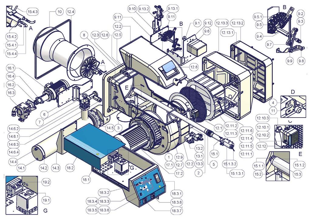
35 BURNER EXPLODED VIEW 34 ITEM DESCRIPTION ITEM DESCRIPTION ITEM DESCRIPTION 1 FLANGE AIR PRESSURE SWITCH 16.1 MOTOR 2 AIR INLET CONE PRESSURE SWITCH BRACKET 16.2 COUPLING 3 CLOSING PLATE AIR DAMPER SILENCER 16.3 PUMP 4 INDEX LABEL AIR INTAKE DAMPER 16.4 BRACKET 5 RING NUT LEVERAGE 17.1 FAN WHEEL 6 PLATE ROD 17.2 MOTOR 7 PLATE JOINT 18.1 BOARD 8 PHOTORESISTOR JOINT 18.2 COVER 9.1 INDEX LABEL CONNECTOR POWER CONTROLLER 9.2 BUSH SPACER FRONT CONTROL PANEL 9.3 BUSH SILENCER LIGHT 9.4 ADJUSTING CAM SHAFT SILENCER LIGHT 9.5 ADJUSTING CAM 13.1 OIL SOLENOID VALVE LOCK-OUT RESET BUTTON ADJUSTING CAM FOIL 13.2 OIL MANIFOLD PROTECTION 9.6 ACTUATOR 13.3 CONNECTOR SWITCH 9.7 LEVERAGE 14.1 PLUG SWITCH 9.8 CAM 14.2 PLUG 19.1 CONTROL BOX 9.9 JOINT 14.3 OIL PRE-HEATER 19.2 IGNITION TRANSFORMER 9.10 BRACKET 14.4 SHEATH 9.11 BRACKET 14.5 RESISTOR 9.12 BRACKET OIL FILTER PRESSURE GOVERNOR GASKET BRACKET GAS BLEEDING VALVE 10 EXTENDED BLAST TUBE THERMOMETER 11 AIR DAMPER INDEX 15.1 STANDARD COMPLETE OIL GUN 12.1 NET NOZZLE 12.2 BURNER HOUSING NOZZLE HOLDER 12.3 FLANGE OIL MANIFOLD 12.4 CERAMIC FIBRE PLAIT RESISTOR 12.5 PRESSURE PLUG 15.2 OIL GUN HOLDER 12.6 INLET 15.3 COMBUSTION HEAD ADJUSTING PIPE 12.7 SCREW LONG IGNITION ELECTRODE 12.8 INSPECTION GLASS LONG IGNITION ELECTRODE 12.9 AIR PRESSURE SWITCH PIPE COMBUSTION HEAD THREADED GAS PIPE IGNITION CABLE
36 35
37 SPARE PARTS DESCRIPTION RN510 RN515 RN520 RN525 CONTROL BOX SIEMENS LAL RIGHT ELECTRODE LEFT ELECTRODE FILTER FOR ECO/DENSE OILДЛЯ SELF-CLEANING PRE-HEATER FILTER FAN WHEEL IGNITION TRANSFORMER ELECTRIC MOTOR ELECTRIC MOTOR SOLENOID VALVE OIL HOSES OIL GUN HOSES OIL GUN HOSES OIL GUN HOSES ADJUSTING CAM FOIL SERVOCONTROL SIEMENS SQL SERVOCONTROL BERGER STM PHOTORESISTOR SIEMENS COUPLING RESISTOR THERMOSTAT TR-TCN-TCI THERMOSTAT TRS PRESSURE GOVERNOR FOR STANDARD VISCOSITY/ECO OIL B B A7 PRESSURE GOVERNOR FOR HIGH VISCOSITY OILPRESSURE GOVERNOR FOR STANDARD VISCOSITY/ECO OIL 25700A A A A7 BURNER MODULATOR (FULLY-MODULATING BURNERS) PUMP FOR ECO/HIGH VISCOSITY OIL SUNTEC NOZZLE mod. FLUIDICS WR STANDARD OIL GUN FOR STANDARD VISCOSITY/ECO OIL EXTENDED OIL GUN FOR STANDARD VISCOSITY/ECO OIL STANDARD OIL GUN FOR HIGH VISCOSITY OIL EXTENDED OIL GUN FOR HIGH VISCOSITY OIL COMBUSTION HEAD C9 STANDARD BLAST TUBE 30910S S S T2 LONG BLAST TUBE 30910S S S T1 IGNITION CABLES OIL HEATER RESISTOR OIL HEATER AUXILIARY RESISTOR (HIGH VISCOSITY/ECO OIL)
38
39
40
41
42
43
44
45 APPENDIX SIEMENS LAL.. CONTROL BOX Use Control and supervision of oil atomization burners For burners of medium to high capacity For intermittent operation (at least one controlled shutdown every 24 hours) Universally applicable for multistage or modulating burners Housing and plug-in base Made of impact-proof and heat-resistance black plastic Lockout reset button with viewing window; located behind it: Lockout warning lamp Lockout indicator coupled to the spindle of the sequence switch and visible in the transparent lockout reset button uses easy-to-remember symbols to indicate the type of fault and the point in time lockout occurred Base and plug-in section of the LAL... are designed such that only burner controls of the LAL... family can be plugged in. 24 connection terminals Auxiliary terminals «31» and «32» 3 earth terminals terminating in a lug for earthing the burner 3 neutral conductor terminals prewired to terminal 2 14 knockout holes for cable entry by means of cable glands 8 at the side 6 in the bottom of the base 6 lateral threaded knockout holes for cable entry glands Pg11 or M20 Operation Flame detector and flame simulation test are made automatically during burner off times and the prepurge time «t1». If loss of flame occurs during operation, the burner control will initiate lockout. If automatic repetition of the startup sequence is required, the clearly marked wire link on the plugin section of the LAL... must be cut away. Pre-conditions for burner startup Burner control is not in the lockout position Sequence switch is in its start position (with LAL2 voltage is present at terminals 11 and 12. Air damper is closed; end switch «z» for the CLOSED position must feed power from terminal 11 to terminal8. Contact of the limit thermostat or pressure switch «W» and the contacts of any other switching devices in the control loop between terminals 4 and 5 must be closed e.g. a control contact for the oil preheater s temperature Normally closed contact of the air pressure switch must be closed. Startup sequence Start command by «R»: «R» closes the start control loop between terminals 4 and 5 The sequence switch starts to run Only prepurging, fan motor at terminal 6 receives power Pre- and postpurging, fan motor or flue gas fan at terminal 7 receives power on completion of «t7» On completion of «t16», the control command for opening the air damper is delivered via terminal 9 Terminal 8 receives no power during the positioning time The sequence switch continues to run only after the air damper has fully closed. t1 Prepurge time with air damper fully open: The correct functioning of the flame supervision circuit is checked during «t1» The burner control will initiate lockout if correct functioning is not ensured. With LAL2: Shortly after the beginning of «t1», the air pressure switch must change over from terminal 13 to terminal 14 otherwise, the burner control will initiate lockout start of the air pressure check. t3 Short preignition time: «Z» must be connected to terminal 16, release of fuel via terminal 18. t3 Long preignition time: «Z» connected to terminal 15. t3n Postignition time: - «Z» must be connected to terminal 15 - With short preignition, «Z» remains on until «TSA» has elapsed connection to terminal 16. t4 Interval «BV1 BV2» or «BV1 - LR»: On completion of «t4», voltage is present at terminal 19. The voltage is required to power «BV2» connected to auxiliary switch «v» in the actuator. t5 Interval: On completion of «t5», terminal 20 receives power. At the same time, control outputs 9 to 11 and input 8 are galvanically separated from the LAL... s control section. LAL... is now protected against reverse voltages from the load control circuit. With the release of «LR» at terminal 20, the startup sequence of the LAL... ends. After a few idle steps (steps with no contact position changes), the sequence switch switches itself off. B Operating position of the burner B-C Burner operation: during burner operation, «LR» drives the air damper to the nominal load or low-fire position, depending on heat demand; the release of the nominal load takes place via auxiliary switch «v» in the actuator and in the event of loss of flame during operation, the LAL... will initiate lockout. For automatic start repetition, the clearly marked wire link «B» on the plugin section of the LAL... must be cut away. C Controlled shutdown: in the case of controlled shutdown, «BV...» will immediately be closed. At the same time, the sequence switch is started to program «t6» C-D Sequence switch travels to start position «A» t6 Postpurge time: fan «M2» connected to terminal 7. Shortly after the start of «t6», terminal 10 receives power and the air damper is driven to the MIN position. Full closing of the air damper starts only shortly before «t6» has elapsed initiated by the control signal at terminal 11. During the following burner off time, terminal 11 is live. t13 Permissible afterburn time: during «t13», the flame signal input may still receive a flame signal. D-A End of control program: start position As soon as the sequence switch has reached the start position having thereby switched itself off the flame detector and flame simulation test will start again. During burner off times, the flame supervision circuit is live. Lockout and indication of the stop position Whenever a fault occurs, the sequence switch stops and with it the lockout indicator. The symbol appearing above the reading mark indicates the type of fault: No start. One of the contacts is not closed (also refer to «Preconditions for burner startup»): Extraneous light: Lockout during or after completion of the control program Examples: nonextinguished flame, leaking fuel valves faulty flame supervision circuit. Interruption of startup. No OPEN signal at terminal 8 from the changeover end switch «a». Terminals 6, 7 and 15 are live until fault has been corrected P Lockout. No air pressure indication at the beginning of the air pressure check. Air pressure failure after the air pressure check. Defect in the flame supervision circuit. Interruption of the startup sequence. No positioning signal at terminal 8 from the auxiliary switch «m» for the low-fire position. Terminals 6, 7 and 15 are live until fault has been corrected. 1 Lockout. No flame signal at the end of the safety time. Flame signa has been lost during operation. A Consenso all avviamento (ad esempio tramite il termostato o il pressostato R dell impianto B Operating position of the burner B-C Burner operation: during burner operation, «LR» drives the air damper to the nominal load or low-fire position, depending on heat demand; the release of the nominal load takes place via auxiliary switch «v» in the actuator and in the event of loss of flame during operation, the LAL... will initiate lockout. For automatic start repetition, the clearly marked wire link «B» on the plugin section of the LAL... must be cut away. C Controlled shutdown: in the case of controlled shutdown, «BV...» will immediately be closed. At the same time, the sequence switch is started to program «t6» C-D Sequence switch travels to start position «A».
46 During burner off times, the flame supervision circuit is live. Lockout indication a-b Startup sequence b-b Idle step (with no contact confirmation) b(b )-a Postpurge program Burner control can immediately be reset after lockout: Do not press the lockout reset button for more than 10 seconds The sequence switch always travels to the start position first After resetting After rectification of a fault that led to shutdown After each power failure During this period of time, power is only fed to terminals 7 and Then, the LAL... will program a new burner startup sequence Specifications Power supply AC 230 V -15 / +10 % for LAL2... on request AC 100 V -15 %...AC 110 V +10 % Frequency 50 Hz -6 %...60 Hz +6 % Absorption AC 3.5 VA Mounting position optional Protection IP 40 Perm. input current at terminal 1 AC 5 A max., 20 A peak Perm. current rating of control terminals 3, 6, 7, , A max., 20 A peak Internal fuse T6,3H250V according to IEC 127 External fuse max. 10 A Weight Device 1000 g Plug-in base 165 g L S H QRC1... SB 1 bl sw br AS br1 a b a ar1 I b ar2 QRB V B W R fr1 a IX 5 b N M1 M2 fr2 FR a b XIV a b VII a b ar3 XI XIII XII b a a b IV II X VIII V VI III b a a b a b a b a b EK1* L1 AR br2 M E BR A SM M 3 AL 21 EK2* 1 (3) 2 H SA 19 9 LR v a z m M 8 LK N Z BV1 BV2 7153a07/0496
47 Sequence diagram Control output at terminal I II III IV V VI a b a b a b a b t7 A t16 t11 t3" t1 t12 t3 t4 t3n t5 B C D t * VII VIII a b a b t IX X a b t2 18 XI a b XII XIII a b a b * t10* t13 XIV a b t8 Lockout position indication Key t1 Prepurge time with air damper fully open t2 Safety time t3 Preignition time, short («Z» connected to terminal 16) T3 Preignition time, long («Z» connected to terminal 15) t3n Postignition time («Z» connected to terminal 15) t4 Interval between voltage at terminals 18 and 19 («BV1-BV2») t5 Interval between voltage at terminals 19 and 20 («BV2» load controller) t6 Postpurge time (with «M2») t7 Interval between start command and voltage at terminal 7 (start delay time for «M2») t8 Duration of startup sequence (excluding «t11» and «t12») t10 Interval from startup to the beginning of the air pressure check t11 Air damper running time to the OPEN position t12 Air damper running time to the low-fire position (MIN) t13 Permissible afterburn time t16 Interval to the OPEN command for the air damper t20 For self-shutdown of the sequence switch

48 C.I.B. UNIGAS S.p.A. Via L.Galvani, Campodarsego (PD) - ITALY Tel Fax / web site: cibunigas@cibunigas.it Note: specifications and data subject to change without notice. Errors and omissions excepted.
PBY1025 PBY1030 PBY1040
 PBY1025 PBY1030 PBY1040 Progressive, Fully-modulating Heavy oil Burners MANUAL OF INSTALLATION - USE - MAINTENANCE BURNERS - BRUCIATORI - BRULERS - BRENNER - QUEMADORES - ГОРЕЛКИ M039126CE Rel. 4.1 04/2010
PG60 PG70 PG81. Progressive / Fully-modulating. Light oil burners MANUAL OF INSTALLATION - USE - MAINTENANCE
 PG60 PG70 PG81 Progressive / Fully-modulating Light oil burners MANUAL OF INSTALLATION - USE - MAINTENANCE BURNERS - BRUCIATORI - BRULERS - BRENNER - QUEMADORES - ГОРЕЛКИ M039191CA Rel: 0.1 09/2011 TABLE
PG30 - PG60 PG70 - PG81
 PG30 - PG60 PG70 - PG81 Double-stage Light oil Burners MANUAL OF INSTALLATION - USE - MAINTENANCE BURNERS - BRUCIATORI - BRULERS - BRENNER - QUEMADORES - ГОРЕЛКИ M03965CE Rel. 4.1 03/2010 TABLE OF CONTENTS
IDEA SERIES LIGHT OIL BURNERS LO280 LO400
 IDEA SERIES LIGHT OIL BURNERS LO280 LO400 MANUAL OF INSTALLATION - USE - MAINTENANCE Complying with EMC 79/336/CEE LV 73/23/CEE C.I.B. UNIGAS spa - Campodarsego (Padova - Italy) M039134CC Rev. 2 05-08
LO60 - LO90. IDEA series Light oil burners
 LO60 - LO90 IDEA series Light oil burners MANUAL OF INSTALLATION - USE - MAINTENANCE BURNERS - BRUCIATORI - BRULERS - BRENNER - QUEMADORES - ГОРЕЛКИ M039136CC Rev. 2.1 06/2016 DANGERS, WARNINGS AND NOTES
LO60 - LO90. IDEA series Light oil burners
 LO60 - LO90 IDEA series Light oil burners MANUAL OF INSTALLATION - USE - MAINTENANCE BURNERS - BRUCIATORI - BRULERS - BRENNER - QUEMADORES - ГОРЕЛКИ M039136CC Rev. 2 04/2008 TABLE OF CONTENTS C.I.B. -
Oil burners fuel unit with solenoid valve
 Oil burners fuel unit with solenoid valve Type VM www.deltapumps.com VM1 - VM4U flanged Certified Quality System Printed in Germany VM_e.pdf - 18.05.08 Page 1/6 Oil burners fuel unit with solenoid valve
Oil burners fuel unit with solenoid valve
 Oil burners fuel unit with solenoid valve Type VM www.deltapumps.com VM1 - VM4U flanged Certified Quality System Printed in Italy - DE112/0404 Oil burners fuel unit with solenoid valve Type VM The DELTA
A AD Oil burners fuel unit. deltapumps.com. DE A-AD_en_0709.pdf Page 1/1
 A AD Oil burners fuel unit deltapumps.com DE116-0709 A-AD_en_0709.pdf - 16.11.09 Page 1/1 Oil burners fuel unit Type A, AD 1- Applications The DELTA aluminium fuel unit type A is an efficient and modern
MANUAL OF - INSTALLATION - OPERATION - MAINTENANCE HEAVY OIL BURNERS
 MANUAL OF - INSTALLATION - OPERATION - MAINTENANCE HEAVY OIL BURNERS PN30 SINGLE STAGE VERSION M03930CC Rev. 02 06/01 Technical Documentation CIB Unigas - Campodarsego (PD) NOTICES THIS MANUAL IS SUPPLIED
Forced draught gas burner
 Installation, use and maintenance instructions Forced draught gas burner Code Model Type 3751982 GAS 3 519T80 291 (3) - 02/2010 DECLARATION Declaration of conformity in accordance with ISO / IEC 17050-1
Light oil burners. One stage operation
 Installation, use and maintenance instructions Light oil burners One stage operation CODE MODEL TYPE 3505 RDB CF 38 50 T3 350050 RDBR CF 6 50 TR 35050 RDBR CF 33 50 TR 35050 RDBR CF 38 50 T3R 350650 RDBR
INSTRUCTION MANUAL FOR OIL BURNER MODELS
 INSTRUCTION MANUAL FOR OIL BURNER MODELS X400 Bio B10 E90-803-001-001-03 Rev 13-1 - Contents Technical specifications Technical data... 3 Working field... 3 Dimensions... 4 Head and electrode settings...
LG/NG/NGX70 LG/NG90. Idea Series Gas burners MANUAL OF INSTALLATION - USE - MAINTENANCE
 LG/NG/NGX7 LG/NG9 Idea Series Gas burners MANUAL OF INSTALLATION - USE - MAINTENANCE BURNERS - BRUCIATORI - BRULERS - BRENNER - QUEMADORES - ГОРЕЛКИ M39135CG Rev. 6.1 1/15 TABLE OF CONTENTS C.I.B. UNIGAS
INSTRUCTION MANUAL FOR OIL BURNER MODELS
 INSTRUCTION MANUAL FOR OIL BURNER MODELS X500 Bio B10 E90-803-001-001-00 Rev 7-1 - Contents Technical specifications Technical data... 3 Working field... 3 Dimensions... 4 Head and electrode settings...
INSTALLATION AND MANINTENANCE INSTRUCTIONS
 INSTALLATION AND MANINTENANCE INSTRUCTIONS Appr. Nr. A 9503 T - 0085 AQ 0765 PEGASUS F2 T HIGH EFFICIENCY GAS-FIRED CAST-IRON BOILERS Models 51-68 - 85-102 2 Contents 1. General technical data 2. Dimensional
Indirect gas-fired air heater
 Indirect gas-fired air heater SERIES HD INSTALLATION AND SERVICE MANUAL MANUFACTURED BY : BROTHERS LIMITED WARNING Improper installation, modification, adjustment or maintenance may cause damage, injury
ATMOSPHERIC GAS BOILER INSTALLATION, OPERATING AND MAINTENANCE MANUAL
 STREBEL GENEVA CE ATMOSPHERIC GAS BOILER INSTALLATION, OPERATING AND MAINTENANCE MANUAL INDEX TABLE 1 TECHNICAL DATA SECTION 1 SECTION 2 SECTION 3 SECTION 4 SECTION 5 SECTION 6 SECTION 7 SECTION 8 SECTION
Forced draught gas burner
 Installation, use and maintenance instructions GB Forced draught gas burner One stage operation CODE MODEL TYPE 3751782 GAS 5 517T80 291 (4) - 07/2015 Declaration of conformity in accordance with ISO /
INSTRUCTION MANUAL FOR OIL BURNER MODELS
 INSTRUCTION MANUAL FOR OIL BURNER MODELS X500-2 Low voltage 12v dc Brushed motor E90-803-001-005-01 Rev 4-1 - Contents Technical specifications Technical data...3 Working field...3 Dimensions...4 Head
Universal fuel unit for oil burners
 Universal fuel unit for oil burners Type U www.deltapumps.com European patent Certified Quality System rinted in Italy - DE115/0404 Universal Fuel Unit for oil burners Type U The DETA Universal Fuel Unit
Light oil - kerosene burner
 Installation, use and maintenance instructions Light oil - kerosene burner One stage operation CODE MODEL TYPE 374374 G3B 437T 90 (4) - 05/0 TECHNICAL FEATURES TYPE 437T Thermal power output 9 35 kw.6
CODE MODEL TYPE PRESS 60 N 616 T PRESS 60 N 616 T80
 Installation, use and maintenance instructions Heavy oil burner CODE MODEL TYPE 3434985 PRESS 60 N 616 T80 3434986 PRESS 60 N 616 T80 291 (2) - 01/2009 Thermal power - Output Operation Fuel Electrical
Light oil / kerosene burner
 Installation, use and maintenance instructions Light oil / kerosene burner One stage operation CODE MODEL TYPE 374445 G5 444T50 290238 (5) - 05/20 TECHNICAL DATA Thermal power output 28 60 kw 2.3 5 kg/h
Installation & Maintenance Manual
 Installation & Maintenance Manual MOL 200 S1L (B30A) Oil Burner 11/12 Tel: +44 (0) 1905 794331 Fax: +44 (0) 1905 794017 Email: info@nu-way.co.uk Web: www.nu-way.co.uk DESCRIPTION COMPONENTS 1. Shrouded
OF INSTALLATION - USE - MAINTENANCE
 LO35 IDEA series Light oil burners MANUAL OF INSTALLATION - USE - MAINTENANCE BURNERS - BRUCIATORI - BRULERS - BRENNER - QUEMADORES - ГОРЕЛКИ M039116CE Rev. 4 02/2008 TABLE OF CONTENTS C.I.B. UNIGAS -
MANUAL OF - INSTALLATION - OPERATION - MAINTENANCE GAS BURNERS
 MANUAL OF - INSTALLATION - OPERATION - MAINTENANCE GAS BURNERS P20 P30 P45 P50 P65 TOWN GAS VERSION M03980CA Rev. 00 01/02 Technical Documentation CIB Unigas - Campodarsego (PD) - Italy NOTICES THIS MANUAL
RL 70/2-100/2-130/2 Low - High Operation
 Installation, use and maintenance instructions Light Oil Burners RL 70/2-100/2-130/2 Low - High Operation C6505052 CONTENTS WARNING TECHNICAL DATA............................. page 3 Burner models.....................................
INSTRUCTION AND MAINTENANCE MANUAL
 Code 007758 0 Edit. 0/009 INSTRUCTION AND MAINTENANCE MANUAL DRYERS A A A A READ THIS MANUAL CAREFULLY BEFORE CARRYING OUT ANY OPERATIONS ON THE DRYER. Cod. 007758 0 - Edition 0/009 - CONTENTS PART A:
15 20 kw kw kw
 Burner Set-up Details 15 20 kw 20 26 kw 29 36 kw Riello RDB2 Please read these instructions carefully before commissioning and using this appliance. To be retained by the householder HEALTH AND SAFETY
ST 40 Oil Burner. Installation & Maintenance Manual
 ST 40 Oil Burner Installation & Maintenance Manual 178 093 13 Thank you for choosing a Nu-way burner. As you would expect from a Company who has a pedigree of more than 75 years in the heating industry,
Parts Available from
 Montage und Bedienungsanleitung Manuel d entretien Installation, use and maintenance instructions Installatie-, gebruiks- en onderhoudsvoorschriften Oδηγίες εγκατάστασης, χρήσης και συντήρησης D F GB NL
INSTRUCTION AND MAINTENANCE MANUAL DRYERS A 11 - A 12 - A 13 - A 14 (R410A)
") Code 007806 0 Edit. 0/04 INSTRUCTION AND MAINTENANCE MANUAL DRYERS A - A - A - A 4 (R40A) READ THIS MANUAL CAREFULLY BEFORE CARRYING OUT ANY OPERATIONS ON THE DRYER. Cod. 007806 0 - Edition 0/04 - CONTENTS
Code 007806 0 Edit. 0/04 INSTRUCTION AND MAINTENANCE MANUAL DRYERS A - A - A - A 4 (R40A) READ THIS MANUAL CAREFULLY BEFORE CARRYING OUT ANY OPERATIONS ON THE DRYER. Cod. 007806 0 - Edition 0/04 - CONTENTS
INSTRUCTION AND MAINTENANCE MANUAL DRYERS A5 - A6 - A7 - A7,5 - A8 - A9 - A10
 Code 00773 04 Edit. 03/0 INSTRUCTION AND MAINTENANCE MANUAL DRYERS A5 - A6 - A7 - A7,5 - A8 - A9 - A0 READ THIS MANUAL CAREFULLY BEFORE CARRYING OUT ANY OPERATIONS ON THE DRYER. Cod. 00773 04 - Edition
RL 28/2-38/2-50/2 Low - High Operation
 Installation, use and maintenance instructions Light Oil Burners RL 28/2-38/2-50/2 Low - High Operation C6505050 CONTENTS WARNING TECHNICAL DATA..............................page 3 Burner models.....................................
Single stage operation oil burner
 Installation & Operating Manual Single stage operation oil burner WARNING NON-RETROFIT APPLICATIONS If this burner is being installed in a packaged unit (ie. burner comes with a boiler or furnace), follow
Oil burners Brûleurs fioul Stookoliebranders
 Installation, use and maintenance instructions Manuel d entretien Installatie-, gebruiks- en onderhoudsvoorschriften GB F NL Oil burners Brûleurs fioul Stookoliebranders One stage operation Fonctionnement
Single stage operation oil burner
 Installation & Operating Manual Single stage operation oil burner WARNING NON-RETROFIT APPLICATIONS If this burner is being installed in a packaged unit (ie. burner comes with a boiler or furnace), follow
Installation & Service Instructions for Jackson & Church Flexaire Packaged Furnaces SDF-125 thru SDF-400 Gas Firing
 Installation & Service Instructions for Jackson & Church Flexaire Packaged Furnaces SDF-125 thru SDF-400 Gas Firing Important: To protect the unit and avoid damage to the heat exchanger, the blower speed
AC6 & AC8 HORIZONTAL SERIES Sealed Metallic Centrifugal Pumps Installation and Maintenance Instructions
 AC6 & AC8 HORIZONTAL SERIES Sealed Metallic Centrifugal Pumps Installation and Maintenance Instructions ASSEMBLY PUMPS WITH MOTORS 1. No assembly required. Unpack the pump and motor and examine for any
IDEA RANGE LIGHT OIL BURNERS LO280 LO400
 IDEA RANGE LIGHT OIL BURNERS LO280 LO400 Compying with EMC 79/336/CEE LV 73/23/CEE Documentazione Tecnica CIB UNIGAS spa - Campodarsego (Padova - Italy) M039134CB Rev. 1 12-06 TABLE OF CONTENTS WARNINGS...
WHE 2.24 / WHE 2.24 FF
 EN Wall-hung gas boilers WHE 2.24 WHE 2.24 FF User Guide 300011777-001-C . Contents 1 Introduction.............................................................................3 1.1 Symbols used...........................................................................................3
Proline GAS HOB Model TCG40IX Instruction Book
 Proline GAS HOB Model TCG40IX Instruction Book GB Operating and Installation Instructions Index Technical data and specifications...... 3 Installation...................... 3-6 Ventilation........................
IDE 20 / IDE 30 / IDE 50 IDE 60 / IDE 80
 IDE 20 / IDE 30 / IDE 50 IDE 60 / IDE 80 EN OPERATING MANUAL OIL HEATER TRT-BA-IDE20-30-50-60-80-TC-001-EN Table of contents Information on the use of this manual... 1 Scope of delivery... 1 General safety...
FLAME115 INFRARED HEATER SERVICE MANUAL INDEX FIRE 115 WARNING
 FLAME115 INFRARED HEATER SERVICE MANUAL INDEX 1. CONTROLS AND COMPONENTS 2. FLAME CONTROL CYCLES 3. MAINTENANCE SCHEDULE 4. TROUBLESHOOTING GUIDE 5. REPAIR PROCEDURES 1. FAN MOTOR ASSEMBLY 2. FUEL FILTER
Installation & Maintenance Manual
 Installation & Maintenance Manual Series NG fully automatic gas burner Models NG125/NG150 : High/Low Gas Burner 11/12 Tel: +44 (0) 1905 794331 Fax: +44 (0) 1905 794017 Email: info@nu-way.co.uk Web: www.nu-way.co.uk
Conversion Instructions Logano G234X. Gas boiler. Please read carefully before installing and servicing. Gas boiler
 Gas boiler UPON COMPLETION OF THE INSTALLATION THE INSTALLER MUST INSTRUCT THE OWNER AND OPERATOR ON THE FUNCTIONALITY AND THE PROPER OPERATION OF THE BOILER AND THE HEATING SYSTEM. INSTALLER MUST REVIEW
Cleaning unit for coolant. :_decftez`_>r_fr] Book No.: V2
![Cleaning unit for coolant. :_decftez`_>r_fr] Book No.: V2](/thumbs/90/104143238.jpg "Cleaning unit for coolant. :_decftez`_>r_fr] Book No.: V2") Cleaning unit for coolant :_decftez`_>r_fr] Book No.: 1271526-02 V2 Alfa Laval Separation AB Separator Manuals, dept. SKEL S-147 80 Tumba, Sweden Telephone: +46 8 53 06 50 00 Telefax: +46 8 53 03 10 40
Cleaning unit for coolant :_decftez`_>r_fr] Book No.: 1271526-02 V2 Alfa Laval Separation AB Separator Manuals, dept. SKEL S-147 80 Tumba, Sweden Telephone: +46 8 53 06 50 00 Telefax: +46 8 53 03 10 40
TWO STAGE HEAVY OIL BURNERS
 TWO STAGE HEAVY OIL BURNERS PRESS N SERIES PRESS 30 N 85/171 342 kw PRESS 45 N 114/205 513 kw PRESS 60 N 171/342 684 kw PRESS 100 N 285/490 1140 kw The PRESS N series of burners covers a firing range from
Providing sustainable energy solutions worldwide. Installation- and maintenance instruction B 30 A
 178 038 51-2 2016-07-08 Providing sustainable energy solutions worldwide Installation- and maintenance instruction B 30 A DESCRIPTION Components 1. Shrouded disc 2. Nozzle 3. Ignition electrodes 4. Nozzle
BENSON LINEAR RADIANT TUBE
 BENSON LINEAR RADIANT TUBE Natural or Propane (Gas fired) I N S T A L L A T I O N C O M M I S S I O N I N G S E R V I C I N G U S E R I N S T R U C T I O N S September 2001 CONTENTS Page Compliance Notices
SIME FORMAT WALL HUNG BOILERS MODEL 34i AND MODEL 34e. cod A
 cod. 6272262A GENERAL DATA Heating Data Heat Output Input (Adjustable) (Adjustable) Format 34i 11.2 34KW 45 145MJ/hr Format 34e 11.2 34KW 45 145MJ/hr General Specifications FORMAT 34i 34e Main burner injectors
RL/1 SERIES. One Stage Light Oil Burners FIRING RATES LIGHT OIL RL 34/1 MZ kw
 The RL/1 burners series covers a firing range from 107 to 398 kw, and it has been designed for use in low or medium temperature hot water boilers, hot air or steam boilers, diathermic oil boilers. Optimisation
SERVICE AND INSTALLATION MANUAL MODELS HDO(H) OIL FOR YOUR SAFETY
 OIL FOR YOUR SAFETY") Bousquet Technologies Inc. 2121, Nobel, Ste Julie, Quebec, Canada, J3E1Z9 SERVICE AND INSTALLATION MANUAL MODELS HDO(H) OIL Oil-Fired air heater for industrial and commercial use. FOR YOUR SAFETY Do not
Bousquet Technologies Inc. 2121, Nobel, Ste Julie, Quebec, Canada, J3E1Z9 SERVICE AND INSTALLATION MANUAL MODELS HDO(H) OIL Oil-Fired air heater for industrial and commercial use. FOR YOUR SAFETY Do not
Merloni Elettrodomestici. Technical Fitting Manual OVENS. Language Issue/Edition Page GB /
 GB 99-11-03/01 1-18 Index 1 WORKING AND FITTED DIMENSIONS 3 1.1 Oven size 60 cm 3 1.2 Maxioven 4 2 INSTALLING THE FITTED OVEN 5 3 FITTED GAS - INSTALLATION REQUIREMENTS 5 4 FIXING THE OVEN TO THE UNIT
V SERIES HDR GAS RANGES
 SERVICE MANUAL ONE POWERFUL PACKAGE V SERIES HDR GAS RANGES TOPS Open Top Hot Top Griddle Top Work Surface BASES Standard Oven Convection Oven Cabinet Base - NOTICE - This manual is prepared for use by
TECHNICAL INSTRUCTIONS
 TECHNICAL INSTRUCTIONS 24-Month Maintenance Kit P/N 58025-06 For BMK2.0LN Boilers Description of Document: This TID provides the procedures to perform recommended 24-Month maintenance on the following
Pellet Boilers. Instructions for Use and Maintenance
 Pellet Boilers Instructions for Use and Maintenance - THE PRESENT MANUAL FORMS AN INTEGRAL PART OF THE BOILER AND MUST BE KEPT FOR FUTURE REFERENCE Bmax Technology - a Division of Elmec Group S.r.l. Localition
TECHNICAL INSTRUCTIONS
 TECHNICAL INSTRUCTIONS 24-Month Maintenance Kit P/N 58015-02 For BMK2.0 (Nozzle Mix) Description of Document: This TID provides the procedures to perform recommended 24-Month maintenance on the following
USERS MANUAL FOR GAS BOILERS
 USERS MANUAL FOR GAS BOILERS PLEASE READ THE MANUAL CAREFULLY: IT CONTAINS IMPORTANT INFORMATION REGARDING SAFETY, INSTALLATION, USE AND MAINTENANCE OF THE APPLIANCE MODELS: NOVADENS 24 NOVADENS 24C NOVADENS
PEGASUS F2 N 2S. CAST IRON GAS BOILER for heating with electronic ignition and flame control INSTRUCTIONS FOR USE, INSTALLATION AND MAINTENANCE
 PEGASUS F2 N 2S CAST IRON GAS BOILER for heating with electronic ignition and flame control INSTRUCTIONS FOR USE, INSTALLATION AND MAINTENANCE cod. 3544309/0 ediz. 01/2003 Carefully read the warnings in
MULTIPLEX SELF RECUPERATIVE gas burner
 Installation - Maintenance MULTIPLEX SELF RECUPERATIVE gas burner SERIES MPSR The Nu-way Multiplex Recuperative System offers the alternative of a self-recuperative burner or a separate recuperator and
USER S INFORMATION MANUAL
 USER S INFORMATION MANUAL HOT WATER HEATING BOILERS DOMESTIC WATER HEATERS 150,000-300,000 Btu/hr MODELS EB-EWU-02 IMPORTANT INSTALLER - AFFIX INSTALLATION MANUAL ADJACENT TO THE BOILER CONSUMER - RETAIN
Mikrofill Ethos Condensing combination boiler. Maintenance Instructions 24cc
 Mikrofill Ethos Condensing combination boiler Maintenance Instructions 24cc IMPORTANT Benchmark Installation, Commissioning and Service Record Log Book is enclosed in your customer information pack. This
INTRODUCTION THIS MANUAL INCLUDES IMPORTANT SAFETY INFORMATION
 INSTALLATION AND OPERATING INSTRUCTIONS FOR THE HARDY Fuel Oil Furnace Models D-140 & D-350 HARDY MANUFACTURING COMPANY, INC. 12345 ROAD 505 PHILADELPHIA, MS 39350 PHONE: (601) 656-5866 FAX: (601) 656-4559
BESB Box Ventilator USA CAN. Product Information. Mechanical Installation. ... Chapter 3. Electrical Installation. ... Chapter 4
 Installation & Operating Manual BESB Box Ventilator USA CAN Product Information... Chapter 1 + 2 Mechanical Installation... Chapter 3 Electrical Installation... Chapter 4 Start Up and Configuration...
Mod. ANBR9..G. CR DOC. NO. GAS-HEATED TILTING BRATT PAN. INSTRUCTIONS FOR INSTALLATION, ADJUSTMENT, USE AND MAINTENANCE...
 -HEATED TILTING BRATT PAN Mod. ANBR9..G. INSTRUCTIONS FOR INSTALLATION, ADJUSTMENT, USE AND MAINTENANCE...page 2-5 APPENDIX....pagina 6-7 Read the manual thoroughly and keep it in a safe place throughout
Light oil burner. Progressive two-stage or modulating operation. Installation, use and maintenance instructions RL 1000/M C10 TC FS X
 Installation, use and maintenance instructions GB Light oil burner Progressive two-stage or modulating operation CODE MODEL TYPE 20050965 RL 1000/M C10 TC FS1 50965X (2) - 11/2012 Original instructions
TECHNICAL INSTRUCTIONS
 TECHNICAL INSTRUCTIONS Benchmark 3.0LN 24-Month Maintenance Kit# 58015-04 This kit applies to units with an Ignitor and a separate gas injector. For units with an Ignitor-Injector (P/N 58023), see Kit
MODULAR AUTOMATIC GRANULAR ICE FLAKER
 MODULAR AUTOMATIC GRANULAR ICE FLAKER INSTRUCTIONS AND WARNINGS 24479 rev. 03 It is strictly forbidden to reproduce this instruction manual or any part thereof. Dear Customer, Congratulations on having
W - WR - WD. Technical information W- WR - WD. Gas-fired convection heaters with fan
 Gas-fired convection heaters with fan W - WR - WD Technical information A2B srl - Via d Ancona, 37-60027 Osimo (An) Tel. 071.723991 - Fax 071.7133153 - Web Site: www.accorroni.it - E-mail: a2b@a-2-b.it
TECHNICAL INSTRUCTIONS
 TECHNICAL INSTRUCTIONS 24-Month Maintenance Kit P/N 58025-04 For BMK3.0LN Boilers Description of Document: This TID provides the procedures to perform recommended 24-Month maintenance on the following
Rif Cod i220-0
 15 52 50 6 13 53 51 2 9 8 3 20 19 18 5 1 7 14 10 4 17 Rif Cod 1 0010060 2 0060287 3 0060310 4 0080003 5 0080004 6 0080051 7 0080053 8 0080410 9 0080413 10 0080430 11 0080432 12 0080434 13 0080435 14 0080436
INSTALLATION, OPERATION AND SERVICE MANUAL GAS COOKER MODEL CPG. Page 1 / 18
 INSTALLATION, OPERATION AND SERVICE MANUAL GAS COOKER MODEL CPG Page 1 / 18 CHAP 1 - INSTRUCTIONS TO PREVENT ACCIDENTS Keep this manual carefully to be able to refer to it in every case of need. Keep appliance
GAS FIRED CONVECTION HEATERS WITH FAN GHIBLI SERIES Models Technical information
 GAS FIRED CONVECTION HEATERS WITH FAN GHIBLI SERIES Models 4-5 - 6 This manual is divided into three sections: Technical information - SECTION 1 - GENERAL INFORMATION It contains all the information relevant
Heating, Air Conditioning, Ventilation. Отопление-Кондиционеры-Вентиляция. MTM 8-30 kw UNIVERSAL OIL HEATER OPERATING MANUAL
 Heating, Air Conditioning, Ventilation Отопление-Кондиционеры-Вентиляция MTM 8-30 kw UNIVERSAL OIL HEATER OPERATING MANUAL 1. Usage MTM 8-30 universal oil heater is designed for heating commercial rooms
INSTALLATION AND OPERATING INSTRUCTIONS GN2. HIGH EFFICIENCY CAST IRON BOILER FOR LIQUID and/or GAS FUELS
 INSTALLATION AND OPERATING INSTRUCTIONS HIGH EFFICIENCY CAST IRON BOILER FOR LIQUID and/or GAS FUELS INDEX 1. Technical information... page 3 2. Dimensional and technical characteristics... page 3 3. Packing
SuperKlean Washdown Products
 DURAREEL DR8 & DR8S INSTALLATION AND MAINTENANCE INSTRUCTIONS **DO NOT THROW AWAY AFTER INSTALLATION** **SAVE AND DISPLAY PROMINENTLY WHERE THIS EQUIPMENT IS USED** GENERAL WARNINGS High pressure and hot
INSTALLATION, OPERATING AND SERVICING INSTRUCTIONS BG 2000-S (V13) RU PL DE IT ES NL EN 1 662Y0600 A
 RU PL DE IT ES NL EN 1 662Y0600 A") INSTALLATION, OPERATING AND SERVICING INSTRUCTIONS G 2000-S 25-35 - 45-55 60-70 - 100 (V13) 1 Index WARNINGS GAS FLOW RATE DIMSIONS SETTINGS PARAMETERS SERVICING THE URNER 3 8 13 OPERATING DESCRIPTION
INSTALLATION, OPERATING AND SERVICING INSTRUCTIONS G 2000-S 25-35 - 45-55 60-70 - 100 (V13) 1 Index WARNINGS GAS FLOW RATE DIMSIONS SETTINGS PARAMETERS SERVICING THE URNER 3 8 13 OPERATING DESCRIPTION
BIX B-One 100 kw INSTALLATION GUIDE
 BIX B-One 100 kw INSTALLATION GUIDE Dear Customer, We thank you for choosing our product. The Bix B-One 100 Kw is a burner of advanced concept and technology, with a high reliability and construction quality.
Providing sustainable energy solutions worldwide. Installation- and maintenance instruction B 45A
 178 017 55-1 2016-05-19 Providing sustainable energy solutions worldwide Installation- and maintenance instruction B 45A DESCRIPTION Components 1. Flame cone 2. Ignition electrodes 3. Nozzle assembly
BESF Box Ventilator USA CAN. Product Information. Mechanical Installation. ... Chapter 3. Electrical Installation. ... Chapter 4
 Installation & Operating Manual BESF Box Ventilator USA CAN Product Information... Chapter 1 + 2 Mechanical Installation... Chapter 3 Electrical Installation... Chapter 4 Start Up and Configuration...
CONDITIONS OF SALE AND WARRANTY
 M.E.P. Mbl 100 Monoblock - Operator s handbook CONDITIONS OF SALE AND WARRANTY 1. Read carefully this operator's handbook before operating our Mbl 100 Monoblock. 2. M.E.P. guarantees his Mbl 100 Monoblock
User s Information Manual
 User s Information Manual Galaxy GG, GXH & GXHA Series, Sentry Series and Sentinel SE Series Gas Boilers with Intermittent Pilot Ignition Device System (IID) FOR YOUR SAFETY: Before operating this boiler,
2.1 BOILER ROOM BOILER ROOM DIMENSIONS 2.3 CONNECTING UP SYSTEM 2.4 CONNECTING UP FLUE 2.5 ELECTRICAL CONNECTION
 FONDERIE SIME S.p.A. of Via Garbo 27 - Legnago (VR) - Italy declares that its diesel-burning boilers are produced in accordance with the requirements of article 3 paragraph 3 of Directive PED 97/23/EEC
AUTOMATIC MODULAR ICE FLAKER
 AUTOMATIC MODULAR ICE FLAKER INSTRUCTIONS AND WARNINGS 24479 rev. 08 It is strictly forbidden to reproduce this instruction manual or any part thereof. 1 5 3 4 Mod. N. V. W 2 2 M8 18 8 18 M8 M8 3 ~ 200
Providing sustainable energy solutions worldwide. Installation- and maintenance instruction MOL1650 T3N 323 2FH.
 178 024 63-2 2016-11-22 Providing sustainable energy solutions worldwide Installation- and maintenance instruction MOL1650 T3N 323 2FH No control DISCRIPTION Components 2 3 4 5 6 7 8 9 18, 19 13 10 17
OPERATING INSTRUCTIONS MANUAL (Please retain for future reference) FVO-200 INDIRECT FIRED SPACE HEATERS
 FVO-200 INDIRECT FIRED SPACE HEATERS") OPERATING INSTRUCTIONS MANUAL (Please retain for future reference) For FVO-200 INDIRECT FIRED SPACE HEATERS CERTIFIED FOR USE IN CANADA AND U.S.A. As per CSA B140.8 Portable Oil Fired Heaters / CSA B140.02003
OPERATING INSTRUCTIONS MANUAL (Please retain for future reference) For FVO-200 INDIRECT FIRED SPACE HEATERS CERTIFIED FOR USE IN CANADA AND U.S.A. As per CSA B140.8 Portable Oil Fired Heaters / CSA B140.02003
Installation & Maintenance Manual
 Installation & Maintenance Manual PO Series Micro Modulating Oil Burner 11/12 Tel: +44 (0) 1905 794331 Fax: +44 (0) 1905 794017 Email: info@nu-way.co.uk Web: www.nu-way.co.uk Contents Page IMPORTANT INFORMATION...
Providing sustainable energy solutions worldwide. Installation- and maintenance instruction B 10 E R
 178 013 03-2 2016-05-26 Providing sustainable energy solutions worldwide Installation- and maintenance instruction B 10 E R DESCRIPTION Components 1. Scale, nozzle assembly 2. Nozzle assembly adjustment
BG2000S PRE-MIX GAS BURNER
 BG000S PRE-MIX GAS BURNER INSTALLATION OPERATION & MAINTENANCE DOCUMENTATION STOKVIS ENERGY SYSTEMS 96R WALTON ROAD EAST MOLESEY SURREY KT8 0DL TEL: 08707 707 77 FAX: 08707 707 767 E-MAIL:info@stokvisboilers.com
Oil TRIANCO. EuroStar Range BURNER DETAILS TRIANCO - OIL BURNER. To be retained by householder
 TRIANCO Oil TRIANCO - OIL BURNER BURNER DETAILS EuroStar Range To be retained by householder TECHNICAL DATA NOZZLE OUTPUT MODEL Output Burner Nozzle Pump Model pressure CO 2 (%) EUROSTAR UTILITY 50/65
Internet Version for Reference Only INDUCED DRAFT COMMERCIAL WATER HEATERS SUPPLEMENT INSTRUCTIONS TO PART #
 INDUCED DRAFT COMMERCIAL WATER HEATERS SUPPLEMENT INSTRUCTIONS TO PART #238-39387-00 THIS INSTRUCTION SUPPLEMENT IS ONLY INTENDED TO GIVE INSTALLATION INSTRUCTIONS AND INFORMATION RELATED TO THE INDUCED
Installation & Maintenance Manual
 Installation & Maintenance Manual MGN 3300-4000 Gas Burner Tel: +44 (0) 1905 794331 Fax: +44 (0) 1905 794017 Email: info@nu-way.co.uk Web: www.nu-way.co.uk CONTENTS BURNER & COMPONENT INDENTIFICATION 3
MONOBLOCK HEAVY OIL BURNERS INSTALLATION, OPERATING AND MAINTENANCE MANUAL
 MONOBLOCK HEAVY OIL BURNERS INSTALLATION, OPERATING AND MAINTENANCE MANUAL ONE STAGE, TWO STAGE AND MODULATING OPERATION ECO 2 ECO 30 ECO 45 www.ecostar.com.tr DEAR USER, ECOSTAR ECO 2, ECO 30, ECO 45
OPERATING AND MAINTENANCE MANUAL
 OPERATING AND MAINTENANCE MANUAL NVPOM-0104 TABLE OF CONTENTS Section Page 1 SPECIFICATIONS...1 1.1 Nova Plus Specifications...1-1 1.2 Warranty...1-2 2 GENERAL BURNER DESCRIPTION...2 2.1 Burner...2-1 2.2
Servicing manual. Wall-mounted condensing gas boiler 600 Series - 11S / 19S / 24S / 24C /2002 GB(EN) For trade use
 For trade use") GB122 7210 1300-12/2002 GB(EN) For trade use Servicing manual Wall-mounted condensing gas boiler 600 Series - 11S / 19S / 24S / 24C Please read thoroughly before attempting to diagnose fault List of contents
GB122 7210 1300-12/2002 GB(EN) For trade use Servicing manual Wall-mounted condensing gas boiler 600 Series - 11S / 19S / 24S / 24C Please read thoroughly before attempting to diagnose fault List of contents
Model No: Little Devil II (inc ss)
") GAS HEATER Model No: Little Devil II (inc ss) PART NO: 6926020, 6926025 (SS) OPERATION & MAINTENANCE INSTRUCTIONS LS1213 INTRODUCTION Thank you for purchasing this CLARKE Gas Heater. Before attempting
GAS HEATER Model No: Little Devil II (inc ss) PART NO: 6926020, 6926025 (SS) OPERATION & MAINTENANCE INSTRUCTIONS LS1213 INTRODUCTION Thank you for purchasing this CLARKE Gas Heater. Before attempting
IMPORTANT SAFETY INSTRUCTIONS DANGER: WARNING:
 IMPORTANT SAFETY INSTRUCTIONS YOUR SAFETY AND THAT OF OTHERS IS PARAMOUNT This manual and the appliance itself provide important safety warnings, to be read and observed at all times. This is the attention
SuperKlean Washdown Products
 February 2012 DURAMIX 8000 INSTALLATION AND MAINTENANCE INSTRUCTIONS **DO NOT THROW AWAY AFTER INSTALLATION** **SAVE AND DISPLAY PROMINENTLY WHERE THIS EQUIPMENT IS USED** WARNING HIGH PRESSURE AND HOT