Coast Spas Manufacturing Inc Street, Langley BC Canada
|
|
|
- Jasper Ryan
- 6 years ago
- Views:
Transcription
1 VERSION Coast Spas Manufacturing Inc Street, Langley BC Canada
2 OWNER S MANUAL 2016 TABLE OF CONTENTS General Information Quick Start Guide Page 3 Page 4 Important Safety Instructions Page 5 Preparation and Set-up for Your New Spa Page 6 Electrical Requirements Page 6 Draining & Winterizing Page 6 Filter Maintenance Page 7 Water Quality Maintenance Page 7-8 MicroSilk Information Page 8 Water Clarity Troubleshooting Page 9 Product & Care Guide Page 10 Glossary of Terms Page 11 Troubleshooting Guide Page Basic Installation and Configuration Guidelines Page 14 Spa Control Page 15+ 2


3 3

4 4
5 OWNER S MANUAL 2016 IMPORTANT SAFETY INSTRUCTIONS READ AND FOLLOW ALL INSTRUCTIONS CAREFULLY DANGER: Risk of Injury. The suction fittings in this hot tub are sized to match the specific water flow created by the pump. Should the need arise to replace the suction fittings or the pump, be sure that the flow rates are compatible. Never operate the hot tub if the suction fittings are broken or missing. Never replace a suction fitting with one rated less than the flow rate marked on the original suction fitting. DANGER: Risk of Accidental Drowning. Do not allow children to be in or around the spa without adult supervision. Keep the spa cover on and locked when not in use. See instructions enclosed with the cover for locking procedures. DANGER: Risk of Electrical Shock. The electrical supply for this product must include a suitably rated switch or circuit breaker to open all ungrounded supply conductors to comply with section of the National Electrical Code, ANSI/NFPA 70. The disconnect must be readily accessible and visible to the hot tub occupant but installed at least 5 feet (1.5 m) from the hot tub water. READ, FOLLOW AND SAVE THESE INSTRUCTIONS a) A green colored terminal or a terminal marked G, Gr, Ground, Grounding or the symbol * is located inside the supply terminal box or compartment. To reduce the risk of electric shock, this terminal must be connected to the grounding means provided in the electric supply service panel with a continuous copper wire equivalent in size to the circuit conductors that supply this equipment. b) At least two lugs marked Bonding Lugs are provided on the external surface or on the inside of the supply terminal box compartment. To reduce the risk of electric shock, connect the local common bonding grid in the area of the hot tub to these terminals with an insulated or bare copper conductor not smaller than No. 6 AWG. c) All field-installed metal components such as rails, ladders, drains or other similar hardware within 5 feet (1.5 m) of the hot tub shall be bonded to the equipment grounding buss with copper conductors not smaller than No. 6 AWG. WARNING: To Reduce the Risk of Injury: The water in a hot tub should never exceed 104 F (40 C). Water temperatures between 100 F (38 C) and 104 F (40 C) are considered safe for a healthy adult. Lower water temperatures are recommended for young children and when hot tub use exceeds 10 minutes. Since excessive water temperatures have a high potential for causing fetal damage during the early months of pregnancy, pregnant or possibly pregnant women should limit hot tub water temperatures to 100 F (38 C). If pregnant, please consult your physician before using a hot tub. Before entering the hot tub, the user should measure the water temperature with an accurate thermometer since the tolerance of water temperature regulating devices may vary as much as +/- 5 F (2 C). Persons suffering from obesity or a medical history of heart disease, low or high blood pressure, circulatory system problems or diabetes should consult a physician before using a hot tub. CAUTION: Risk of Hyperthermia: Hyperthermia occurs when the internal temperature of the body reaches a level several degrees above the normal body temperature of 98.6 F (37 C). The symptoms of hyperthermia include drowsiness, lethargy, and an increase in the internal temperature of the body. Prolonged immersion in hot water may induce hyperthermia. A description of the causes, symptoms, and effects of hyperthermia are as follows: Unawareness of impending hazard; Failure to perceive heat; Failure to recognize the need to exit hot tub; Physical inability to exit hot tub; Fetal damage in pregnant women; and Unconsciousness and danger of drowning. WARNING: Children should not use hot tubs without adult supervision. WARNING: Do not use hot tubs unless all suction guards are installed to prevent body and hair entrapment. WARNING: People with infectious diseases should not use a hot tub. WARNING: To avoid injury, exercise care when entering or exiting the hot tub. WARNING: Do not use drugs or alcohol before or during the use of a hot tub to avoid unconsciousness and possible drowning. The use of alcohol or drugs can greatly increase the risk of fatal hyperthermia in hot tubs. WARNING: Pregnant or possibly pregnant women should consult a physician before using a hot tub. WARNING: Water temperature in excess of 38 C (100 F) may be injurious to your health. Before entering the hot tub, measure the water temperature with an accurate thermometer. WARNING: Do not use a hot tub immediately following strenuous exercise. WARNING: Prolonged immersion in a hot tub may be injurious to your health. WARNING: Do not permit electric appliances (such as lights, telephone, radio, television, etc.) within 5 feet (1.5m) of this hot tub unless such appliances are built-in by the manufacturer. WARNING: People using medication and/or having an adverse medical history should consult a physician before using a spa or hot tub. CAUTION: Observe a reasonable time limit when using the hot tub. Long exposures at higher temperatures can cause high body temperature. Symptoms may include dizziness, nausea, fainting, drowsiness, and reduced awareness. These effects could possibly result in drowning. CAUTION: Enter and exit the hot tub slowly. Wet surfaces can be very slippery. CAUTION: Proper chemical maintenance of hot tub water is necessary to maintain safe water and prevent possible damage to hot tub components. Maintain water chemistry in accordance with manufacturer s instructions. CAUTION: Use the straps and clip tie downs to secure the cover when not in use. This will help to discourage unsupervised children from entering the hot tub and keep the hot tub cover secure in high-wind conditions. There is no representation that the cover, clip tie-downs, or actual locks will prevent access to the hot tub. CAUTION: For exercise, the water should not exceed 90 F (32 C). CAUTION: When using this electrical equipment, basic safety precautions should always be followed. 5
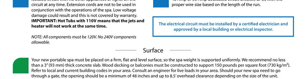
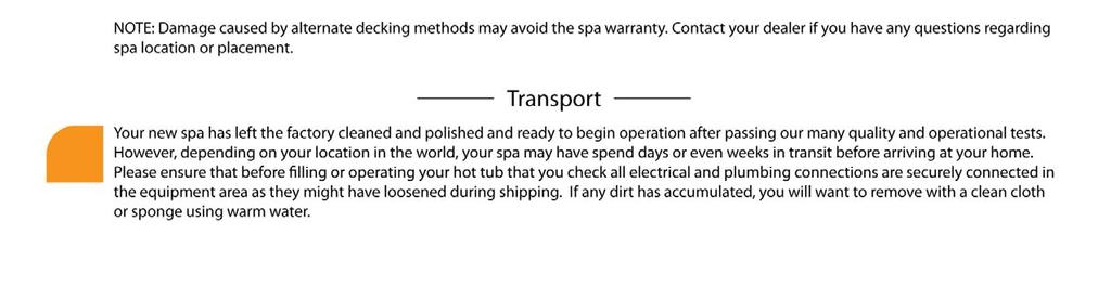
6 OWNER S MANUAL 2016 PREPARATION AND SET-UP FOR YOUR NEW SPA LOCATION FOR YOUR NEW SPA: You want to keep in mind how you intend to use the spa and plan the location accordingly. How close is the spa from the exit or entrance to your house? (consider the cold weather) Is the path to your spa clean of debris, sand, grass? (so as not to track into the spa) Is there protection from wind, inclement weather? Can neighbors or passersby see the spa? NOTE: Allow for service access: Many spa owners enjoy placing their spa in a decorative enclosure or a deck. Keep in mind that you need to have access to the equipment for maintenance and the spa should be able to be moved or lifted without destroying the special enclosure or its surroundings. You should discuss this with your dealer when designing the location. Extension cords are not to be used in conjunction with the operations of the spa. Low voltage damage could result and this is not covered by warranty. NOTE: All components must be 120V; No 240V components allowable. 240VAC: Depending on the model of spa, it will require either a 40 Amp or 50 Amp dedicated circuit breaker, GFCI, with the proper wire size based on the length of the run. The electrical circuit must be installed by a certified electrician and approved by a local building or electrical inspector. ELECTRICAL REQUIREMENTS All self contained spas use 120VAC or 240VAC electrical spa packs.. These instructions describe the only acceptable electrical wiring procedures. Spas wired in any other way will void your warranty and may result in serious injury. All installations should be completed by a certified electrician. Failure to comply with state and local codes may result in fire or personal injury and will be the sole responsibility of the spa owner. 120VAC: This requires an isolated 20 Amp circuit breaker. This needs to be an isolated circuit with no other appliances or lights on this circuit at any time. Extension cords are not to be used in conjunction with the operations of the spa. Low voltage damage could result and this is not covered by warranty. NOTE: All components must be 120V; No 240V components allowable. 240VAC: Depending on the model of spa, it will require either a 40 Amp or 50 Amp dedicated circuit breaker, GFCI, with the proper wire size based on the length of the run. The electrical circuit must be installed by a certified electrician and approved by a local building or electrical inspector. SURFACE AND PAD REQUIREMENTS Your new portable spa must be placed on a firm, flat and level surface, so the spa weight is supported uniformly. We recommend no less than a 3 (93 mm) thick concrete slab. Wood decking or balconies must be constructed to support 150 pounds per square foot (730 kg/m²). Refer to local and current building codes in your area. Consult an engineer for live loads in your area. Should your new spa need to go through a gate, the opening should be a minimum of 48 inches and up to 8.5 overhead clearance depending on the size of the unit. NOTE: Damage caused by alternate decking methods may avoid the spa warranty. Contact your local dealer if you have any questions regarding spa location or placement. DRAINING AND WINTERIZING DRAINING YOUR SPA After a period of 3-4 months, detergent residues from bathing suits and soap film will build up in your spa water. Once this happens, your spa water will appear cloudy and should probably be replaced. Turn power OFF at the breaker. Locate the drain valve (usually in the equipment area). Remove the safety cap and attach garden hose. Drain water to a convenient area. (Spa water may harm grass or plants if sanitizer levels are high.) When water begins to flow out of the hose, open the air relief valve located on filter lid (Hydro-Cyclonic Filtration) or Air Bleeder Valve (Skim Filtration) Your spa will drain except for a small portion left in the foot well. This can be removed with a sponge and pail. Once empty, clean as required. To finish, remove garden hose and attach safety cap. IMPORTANT (Cascade Series Only): There will be an additional drain valve. This is connected directly to the tank reservoir and you will see the water level go down on the sight tube in the equipment area. WINTERIZING YOUR SPA In many areas of the world the temperature may drop below 32 F (0 C). We recommend the spa is always filled with water and running at normal spa temperatures. By doing this you will minimize the risk of freezing within your spa. If it is necessary to leave your spa unattended for long periods of time during cold weather conditions, you should drain your spa to avoid accidental freezing caused by power outages. Your local dealer can perform the following winterizing procedures, if you are not completely comfortable with them. Ensure that you have fully drained the spa (Refer to the DRAINING YOUR SPA section) After draining, your spa may still have water remaining in the equipment and plumbing fittings. Disconnect the hand-tightened union fittings going to and from the jet pumps. Be careful not to lose the o-rings between the unions and pump housing. Leave drain valve in the open position and safety cap off. To completely drain the plumbing lines, a wet/dry shop vacuum can be used to draw out any remaining water. Place the vacuum hose over the jet fittings in the 6
 Remove the filter cartridge and store in a warm, dry area. Clean the spa shell and place spa cover on spa.")


7 OWNER S MANUAL 2016 spa as well as the plumbing lines in the equipment area. You should also disconnect the plug on the crystal clear inspection tube (if installed) Remove the filter cartridge and store in a warm, dry area. Clean the spa shell and place spa cover on spa. Be sure to lock the cover in place in case of high winds or rain. WARNING: The instructions above should be followed accordingly when winterizing your spa however they are guidelines and potential freeze damage may still occur. All freeze damage is the sole responsibility of the spa owner and will not be covered by the warranty should it occur. EMERGENCY SITUATIONS: To eliminate freezing in the event of equipment failure, use a 100-watt light bulb or small heater via extension cord and place it in the equipment area, keeping it away from plumbing lines. This will help for a short period of time until proper service can be rendered. FRONT ACCESS SKIMMER/FILTER Turn power OFF at the breaker. Pull open skimmer weir door. Reach in and remove skimmer basket. Pull straight up and out to remove basket. Clean out debris. Remove diverter plate. Remove filter cartridges. Clean with a garden hose and high-pressure nozzle. Periodically you may need to soak your filter in a cartridge filter cleaner to remove excess minerals and/or oils. Rinse filter thoroughly before installing. Reverse this procedure to re-install the filter cartridges. Put pump one on low speed this will help pull the cartridge into place. WATER QUALITY MAINTENANCE FILTER MAINTENANCE The spa filter is one of the most important maintenance items of a hot tub. The filter is there to remove debris from the water and needs to be cleaned on a regular basis. Failure to do so may result in poor performance, poor water clarity and could prevent the spa from heating. Filtration starts as soon as flow is steady through the filter. As the filter cartridge removes the debris from the spa water, the accumulated debris causes flow resistance. CLEANING AND REPLACING FILTER CARTRIDGE Your spa filter has been designed for quick and easy maintenance. The filter cartridge should be rinsed by hose once a week and cleaned with a cartridge cleaner once a month. A second filter cartridge is recommended and will speed up this process. This can be purchased from your local dealer. Look for these specialized cleaning attachments at your local dealership. Maintaining the quality of the water within the specified limits will serve to enhance your enjoyment and prolong the life of the hot tub s equipment. It is a fairly simple task, but it requires regular attention because the water chemistry involved is a balance of several factors. There is no simple formula, and there is no avoiding it. An indifferent approach to water maintenance will result in poor and potentially harmful conditions for soaking and even damage to your hot tub investment. The most important thing to keep in mind is that preventing poor water chemistry is much easier than correcting poor water chemistry. For specific guidance on maintaining water quality, consult your Authorized Dealer who can recommend appropriate chemical products for sanitizing and maintaining your hot tub. MAINTAIN HEALTHY SPA WATER Important! When maintaining your hot tub s water chemistry, ensure that your cover is removed during any aggressive treatments to allow for dissipation into the air. Take care to remove the cover slowly and let chemicals deplete if you are uncertain if your water is properly balanced. Always maintain your hot tub s water chemistry within the following parameters: ph: ph is a measure of relative acidity or alkalinity of water and is measured on a scale of 0 to 14. The midpoint of 7 is said to be neutral, above which is alkaline and below which is acidic. In hot tub water, it is very important to maintain a slightly alkaline condition of 7.2 to 7.8. Problems become proportionately severe the further outside of this range the water gets. A low ph will be corrosive to metals in the hot tub equipment. A high ph will cause minerals to deposit on the interior surface (scaling). In addition, the ability of the sanitation agents to keep the hot tub clean is severely affected as the ph moves beyond the ideal range. That is why almost all hot tub water test kits contain a measure for ph as well as sanitizer. Sanitizer (Chlorine or Bromine): To destroy bacteria and organic compounds in the hot tub water by breaking them down into non-harmful levels which get filtered out. A sanitizer must be used regularly, either 7
8 OWNER S MANUAL 2016 chlorine or bromine. Sanitizing your spa water is the most important spa maintenance you can do for yourself. Total Alkalinity: This refers to the ability of the hot tub water to resist changes in ph. Controlling alkalinity can help keep your ph in the appropriate range thereby lessening the need for ph balancing. If the TA is too low the ph level will fluctuate rapidly from high to low. If the TA is too high the ph will tend to be too high and will be very difficult to bring back down. Calcium Hardness: This is a measurement of dissolved calcium in the water. Calcium will help control the corrosive nature of the spa s water. WARNING: Never store chemicals inside the equipment area of your spa. IMPORTANT: Do not use Hydrogen Peroxide based sanitizers in your spa. When using Chlorine or Bromine tablets you must use a floating dispenser. These chemicals can have an extremely corrosive effect on certain materials in the spa. Damage caused by use of these chemicals, or improper use of any chemicals, is not covered under the spa s warranty. OTHER ADDITIVES: Many other additives are available for your spa. Some are necessary to compensate for out-of-balance water, some aid in cosmetic water treatment and others simply alter the feel or smell of the water. Your Authorized Dealer can advise you on the use of these additives. There is an adjustment valve along the water supply line to the MicroSilk generator that varies the air/water ratio that enters into the system. This adjustment is extremely sensitive and turning the adjustment valve only 1 mm can greatly effect the level of MicroSilk production. When your spa leaves the factory, it has been tested and the valve position marked for optimum MicroSilk production. Once activated, you will be able to see a white cloud of silky water coming from the specialized fitting in your spa. Depending on the size of your hot tub you should see your entire spa filled with oxygen rich micro bubbles within minutes (more water capacity equals a longer duration until the entire hot tub fills with white silky water). TROUBLESHOOTING If your spas MicroSilk production seems slow, or lower than normal: Ensure that the air supply line is clear of any debris. Verify that water is flowing to the MicroSilk generator. Check the air/water mixture valve. Return to factory settings by aligning factory placed marks. To adjust: make incremental (1 mm) turns and wait at least 90 seconds before making further adjustments. Shut power off at breaker and make sure all electrical, water and air lines have a good connection to the MicroSilk Generator. MICROSILK ABOUT MICROSILK MicroSilk produces a silky white cloud of micro bubbles that are small enough to enter the pores of your skin. When the micro bubbles enter the pores of your skin they absorb foreign contaminants and release oxygen. This process improves collagen production, leaving skin feeling smooth and healthy. Using the MicroSilk System on a regular basis greatly reduces the appearance of wrinkles and your skin will appear younger and firmer after only a short period of time. TREATING SKIN CONDITIONS MicroSilk is used to treat various skin conditions including: Eczema, Psoriasis, Ichthyosis and aids in reducing scar tissue. More information is available from your local dealership. OPERATION MicroSilk is produced by a unique piece of equipment, the MicroSilk Generator, that roughly resembles a jet pump and is located in your equipment area. The MicroSilk generator is powered by your hot tub and controlled using your main control panel. The MicroSilk Generator requires both water and air to function. Water is supplied from the water in your hot tub and an independent air line connects from a small grate-like fitting from above your spas waterline providing the oxygen needed for MicroSilk production. 8
9 OWNER S MANUAL 2016 WATER CLARITY TROUBLESHOOTING PROBLEM PROBABLE CAUSE POTENTIAL SOLUTIONS Water Odor Improper sanitization Excessive organics in water ph is too low Add sanitizer Shock spa with sanitizer Adjust ph Chlorine Odor Chloramines are too high ph is too low Shock spa with sanitizer Adjust ph Musty Odor Bacteria or Algae growth Shock spa with sanitizer Drain and refill spa water Scale Total alkalinity is too high ph is too high High calcium content in water Adjust total alkalinity Adjust ph Use stain and scale product Stains Total alkalinity is too low ph is too low High metal content in water Adjust alkalinity Adjust ph Use stain and scale product Cloudy Water Poor filtration ph is too high Hardness is too high Total alkalinity is too high Suspended particles Clean filter cartridge Adjust ph Adjust hardness Adjust total alkalinity Drain and refill spa water Algae Growth ph is too high Sanitizer is too low Adjust ph Shock spa with sanitizer Adjust sanitizer level Eye Irritation ph is too low Sanitizer is too low Adjust ph Shock spa with sanitizer Adjust sanitizer level Skin Rash/Irritation Free chlorine level too high Unsanitary water Adjust chlorine level Shock spa with sanitizer Adjust sanitizer level 9
10 OWNER S MANUAL 2016 PRODUCT & CARE GUIDE Your Authorized Dealer carries a wide variety of care and maintenance products. For more information please contact your Dealer. REQUIRED FILTER MAINTENANCE Your new hot tub is equipped with a filter cartridge. To ensure maximum water quality at all times, you should replace the filter cartridge every six months, or earlier as necessary. The filter cartridge is designed to be thrown away! Attempts to re-use the filter cartridge may result in the rerelease of unwanted particles back into the hot tub. REQUIRED WATER REPLACEMENT You should replace the hot tub s water every 3-6 months. The frequency will depend on a number of variables including frequency of use, number of bathers and attention paid to the water quality maintenance. You will know it is time for a change when you can no longer get the normal feel or sparkle to the water, even though the key water balance measurements are all within the recommended ranges. HEADREST / PILLOW CARE The pillows can be removed for easy cleaning and maintenance. All pillows have plugs within the pillow itself. To remove the pillow, grab the bottom edge firmly and pull outward. This will allow the pillows to popout from the receptacle in the spa shell. To reinstall the pillow you will align the pillow plug with the receptacle. Press/hit the front side of the pillow firmly, which will insert the plug back into the receptacle. Proper water chemistry must be maintained. Your hot tub pillows are easily and quickly damaged when exposed to unbalanced spa water. If you suspect that your chemicals may be unbalanced, remove your pillows immediately until the water has been restored to suggested conditions. Do not sit on the pillows Do not pull on the pillows Pillows should be cleaned using a soft cloth and mild soap, then wiped with a conditioner. We recommend that pillows be washed each time you drain you spa. HOT TUB INTERIOR Your hot tub has a fiberglass reinforced acrylic shell. Generally dirt and stains will not adhere to the surface. To properly clean the surface, we recommend wiping it with a soft damp cloth (or sponge) using household soap or liquid detergent and rinsing thoroughly with fresh water. Stubborn dirt or stains may be removed by using Spic & Span adequately dissolved in water. Contact your dealer and inquire about maintenance packages. STAINLESS STEEL CONTROLS AND COMPONENTS ABOVE THE WATER LINE To preserve the stainless steel finish of the controls and components above the water line, we recommend they be wiped with a dry soft cloth after each use of your hot tub. In addition, off-gas your tub by removing the cover for approximately 30 minutes multiple times per week (if not in use) and after every shock treatment. COVER CARE A well cared for spa cover is a thing of beauty in its own right. Be sure to clean and condition your cover at least once a month more often if needed. Your cover needs to be cleaned and conditioned because vinyl can be dry and become brittle, spoiling your spa s appearance. Dry, brittle vinyl can also tear at the seams and stress points. Quality materials, internal sewn reinforcing and careful workmanship can only go so far against the ravages of Mother Nature. See the specific Warranty card enclosed with your cover for further details. When you shock your spa you need to remove the cover for a minimum of 30 minutes to ensure that the chemical gas off can escape from the spa. You are required to keep the spa covered at all time when not in use to protect the shell from harmful UV rays. A covered spa will use less electricity when maintaining the desired water temperature See the manual that comes with the cover for proper mounting of the cover locks The cover should remain locked at all times to prevent unauthorized entry into the spa and potential drowning. Do not Sit, Stand or Lie on your cover. Nor should you place any heavy object on top of the cover as this may damage the structure. VERY IMPORTANT: We recommend a vinyl conditioner for your spa cover. Your local dealer carries a wide variety of care and maintenance products. Choose a pleasant day each month to remove your cover from the spa and lay it on a flat surface accessible by garden hose. Douse the cover with a healthy amount of water from the hose or a bucket to rinse away loose dirt or debris. Using a soft bristle brush and a mild solution of dishwashing liquid (about one teaspoon of detergent to two gallons of water), and with a gentle circular motion, scrub the cover clean. Be careful not to let any areas of the cover dry before they re thoroughly rinsed. Now apply the vinyl conditioner as directed on the container. Massage the conditioner into the cover in a gentle but firm manner. Before replacing the cover on your spa, wipe and rinse any dirt from the bottom of the cover. When you are ready, put the cover on the spa. NOTE: To remove tree sap, use lighter fluid (not charcoal lighter but the fluid used in cigarette lighters). Use sparingly, then immediately apply conditioner to that area. DO NOT use any cleaning products containing abrasives or solvents, since these could damage the surface. Harsh chemicals should never be used on acrylic surfaces. Damage to the shell due to the use of harsh chemicals is not covered under the warranty. DO NOT leave your hot tub drained and in direct sunlight for extended periods of time. Extreme heat could cause damage to the acrylic surface and may induce an effect known as crazing. 10
11 OWNER S MANUAL 2016 GLOSSARY OF TERMS AIR CONTROL VALVE: Mounted generally on the lip of the spa, it induces warm air from the equipment enclosure into the jet stream through venturi action. HEATER: The electronically controlled heater raises the temperature of the spa to the desired setting. LEDs: LEDs and their special lenses can be used to achieve the desired mood lighting in the spa and spa jets. WATER DIVERTER VALVE: The large diverter is used to divert water to various seats in the spa. ON/OFF DIVERTER VALVE: The smaller diverter is used to control water flow and to turn on/off the neck jets and/or waterfalls. FILTER AIR RELIEF VALVE: Located on top of dome filter lid. Used to release air from the filter. SKIMMER BLEEDER VALVE: Located in the skimmer area, needs to be loosened while filling the spa. This will help eliminate air from being trapped in the spa equipment. SKIMMER: This is the rectangular outlet at the water level. The skimmer removes surface debris to the filter. The water level in the spa should be kept ½ to ¾ up on the skimmer for optimum operation. SUCTION FITTING: During operation of the equipment, the suction works in conjunction with the skimmer to draw water from the bottom of the spa through the filter, keeping the spa sparkling clean. NECK JET: Direction-controllable jet for soothing neck massage. ADJUSTABLE CLUSTER JET: Our adjustable, high-intensity hydrotherapy jet. OZONATOR: Available as an option. The ozonator produces natural ozone through the Corona Discharge process. Continuous use of an ozonator can dramatically reduce sanitizer consumption. CONTROL BOX (Pack): Basically the heart of the spa. Power is distributed to any/all functions of the spa: pumps, ozonator, LED lighting, heater element, etc. DIRECTIONAL JET: Provides a straight flow for a therapeutic massage ROTATIONAL JET: Provides a Uni-directional circular therapeutic massage. MASSAGE JET: Delivers massage in staccato bursts over a narrow, focused area. CONTROL PANEL: Mounted on the top lip of the spa and controls the functions of the spa. VOLCANO/WHIRLPOOL JET: high-output jet designed for foot and leg massage. DRAIN VALVE: Used in draining of the spa. Normally located in the equipment area. LAMINAR FLOW WATER FEATURE: A thin stream of water that arcs from the spa lip EQUIPMENT ENCLOSURE: An enclosure that houses the control box, pump(s) and other electrical components. FILTER: The filter cleans the spa by passing water through a filter cartridge where debris and impurities are removed. Top load filter means the filter cartridge is accessible through the top of the spa. Front access skimmer means cartridge is accessed through door of skimmer. FLOOR DRAIN: The floor drain is covered by a grate-type cover and is utilized when draining the spa. It also acts as the return for the ozonator. You will see bubbles emitted from this drain, which is the result of water mixing with the ozone output. GATE VALVES: Red with a grey handle is located at the inlet and outlet of the pumping system. Used while servicing the spa equipment, the valves open or close the water flow to the equipment. To remain open for normal use, turn fully counterclockwise. KNIFE VALVES: A white T -handled valve, same functions as Gate valve (see above), except to open them you pull up on handle. 11
12 OWNER S MANUAL 2016 SPA SYSTEM TROUBLESHOOTING GUIDE SYMPTOM PROBABLE CAUSE RECOMMENDED ACTION Spa does not work Power is turned off Reset GFCI No display on the control panel Power is turned off Defective topside control Reset GFCI Contact your Dealer Letters on the control panel An error has been found Refer to the Reference Card for your control panel to verify the error. Contact your Dealer for service PUMP PROBLEMS SYMPTOM PROBABLE CAUSE RECOMMENDED ACTION Noisy/Loud motor Air trapped in the pump Low water level Worn pump seal Defective pump Open bleed valve in the skimmer Add water to the spa Contact your Dealer Contact your Dealer Pumps power down on their own Set temperature has been reached Filtration cycle has ended Automatic time out Overheat safety protection No problem No problem Pumps are set to run for a predetermined time while the spa is in use (15-20 Mins) The pumps have a thermal overload which will prevent them from running for extended periods of time. Wait until pumps have cooled down (1+ hrs). If problem persists, contact your Dealer. Pump running constantly, will not Filter cycle set to 24 hours Turn off 24 hour filtration turn off Problem with the circuit board Turn power off at GFCI and contact your Dealer Pump will not turn on GFCI tripped Motor has overheated Not plugged in Damaged plug Seized motor Blown fuse Motor vent is blocked Reset the GFCI Let cool for 1+ hour Plug in to the board Contact your Dealer Contact your Dealer Check fuse or contact your Dealer Clear debris from the vent 12
13 OWNER S MANUAL 2016 HEAT PROBLEMS PROBABLE CAUSE RECOMMENDED ACTION Water will not heat Error message on control panel Refer to the Reference Card for your control panel to Spa is in a different Heat Mode verify the error Set spa to Standard Mode Water level is too low Add water to the spa Poor water flow Clean filter & check valves Closed valves Open all valves Pump 1 is not running Contact your dealer Water is too hot Incorrect reading Verify temperature with thermometer Filter cycle duration is too long Reduce duration of the filter cycle Pump speeds reversed Contact your dealer Water will not maintain heat Cover is off for extended periods of time in cold weather / cold wind. Put cover back onto hot tub and allow for heat to regenerate. Call your dealer if temperature does not Hot tub is wired for 110V and jets are on. increase. Hot tubs wired for 110V only have enough power to heat or operate pumps. Turn off jets to power heater. LIGHTING ISSUES PROBABLE CAUSE RECOMMENDED ACTION Standard light will not come on Bulb has burnt out Replace the light bulb LED lighting not in sync Burnt out bulb/connection Contact your dealer LED lighting won t come on Incorrect settings Contact your dealer PUMPS WILL NOT PRIME PROBABLE CAUSE RECOMMENDED ACTION Pump on but no water flow Air trapped in pump No water in the pump Closed valves Loosen bleed valve in skimmer Check the fill level in the spa Open all valves HYDROTHERAPY JETS PROBABLE CAUSE RECOMMENDED ACTION Little to no water flowing from jets Jets turned off Pump not primed Valves are closed Diverter set to a different seat Dirty filter Open jet by turning the face counter clockwise Reset breaker to allow for the spa to prime the pump. Open bleed valve in the skimmer area Open valves Switch diverter Remove and clean filter cartridge PLUMBING SYSTEM PROBABLE CAUSE RECOMMENDED ACTION Water around base of spa Loose connections Leak from internal fitting Hand tighten all quick disconnects and fittings. Check gaskets and o-rings Contact your dealer 13
14 OWNER S MANUAL 2016 BASIC INSTALLATION AND CONFIGURATION GUIDE- LINES Warning! Qualified Technician Required for Service and Installation Use minimum 6AWG copper conductors only. Torque field connections between 21 and 23 in lbs. Readily accessible disconnecting means to be provided at time of installation. Permanently connected power supply. Connect only to a circuit protected by a Class A Ground Fault Circuit Interrupter (GFCI) or Residual Current Device (RCD) mounted at least 5 (1.52M) from the inside walls of the spa/hot tub and in line of sight from the equipment compartment. CSA ENCLOSURE: TYPE 2 Refer to Wiring Diagram inside the cover of the control enclosure. Refer to Installation and Safety Instructions provided by the spa manufacturer. Warning: People with infectious diseases should not use a spa or hot tub. Warning: To avoid injury, exercise care when entering or exiting the spa or hot tub. Warning: Do not use a spa or hot tub immediately following strenuous exercise. Warning: Prolonged immersion in a spa or hot tub may be injurious to your health. Warning: Maintain water chemistry in accordance with the Manufacturers instructions. Warning: The equipment and controls shall be located no less than 1.5 meters horizontally from the spa or hot tub. CSA COMPLIANCE Caution: Test the ground fault circuit interrupter before each use of the spa. Read the instruction manual. Adequate drainage must be provided if the equipment is to be installed in a pit. For use only within an enclosure rated CSA Enclosure 3. Connect only to a circuit protected by a Class A ground fault circuit interrupter or residual current device. To ensure continued protection against shock hazard, use only identical replacement parts when servicing. Install a suitably rated suction guard to match the maximum flow rate marked. Warning: Water temperature in excess of 38 C may be injurious to your health. Disconnect the electrical power before servicing. WARNING! GFCI OR RCD PROTECTION. The Owner should test and reset the GFCI or RCD on a regular basis to verify its function. WARNING! SHOCK HAZARD! NO USER SERVICEABLE PARTS. Do not attempt service of this control system. Contact your dealer or service organization for assistance. Follow all owner s manual power connection instructions. Installation must be performed by a licensed electrician and all grounding connections must be properly installed. Disconnect the electric power before servicing. Keep access door closed. 14
15 TP600 and TP400 Control Panels Balboa Water Group Revolution Series User Interface and Programming Reference Standard Menus System Model: BP1500 / BP Other BP-Series Systems as required. Software Version: 7.0 and later Panel Model: TP600 Series TP400 Series Software Version: 2.3 or later 2.4 or later JETS J AUX A LIGHT HEAT 1
16 Main Menus Navigation Navigating the entire menu structure is done with 2 or 3 buttons on the control panel. Some panels have separate WARM (Up) and COOL (Down) buttons, while others have a single Temperature button. In the navigation diagrams Temperature buttons are indicated by a single button icon. Panels that have two Temperature buttons (Warm and Cool) can use both of them to simplify navigation and programming where a single Temperature icon is shown. The LIGHT Button is also used to choose the various menus and navigate each section. Typical use of the Temperature button(s) allows changing the Set Temperature while the numbers are flashing in the LCD. Pressing the LIGHT button while the numbers are flashing will enter the menus. The menus can be exited with certain button presses. Simply waiting for several seconds will return the panel operation to normal. Power-up Screens Each time the System powers up, a series of numbers is displayed. After the startup sequence of numbers, the system will enter Priming Mode (See Page 3). Key Indicates Flashing or Changing Segment Indicates Alternating or Progressive Message - every 1/2 second A temperature button, used for Action Light or dedicated Choose button, depending on control panel configuration Waiting time that keeps the last change to a menu item. Waiting time (depends on menu item) that reverts to original setting and ignores any change to that menu item. SET RANGE While the Temperature is still flashing, press Light. Light Cycle if enabled Indicates a Menu Item that Depends on a Manufacturer Configuration and may or may not appear. SET RANGE SET READY SET P 1 SET If Time of Day is not set SET TIME will appear in this menu. 2 Waiting Several Seconds in the Main Menu will allow the display to revert to the. Most changes are not saved unless Light is pressed. Refer to Key above. 2
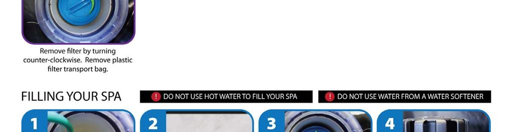
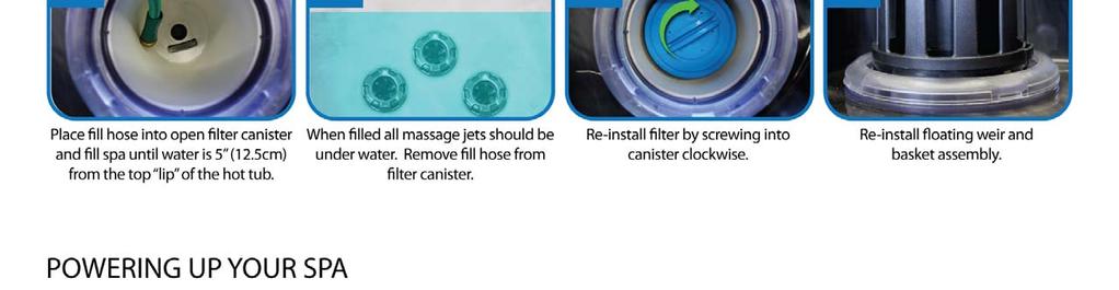
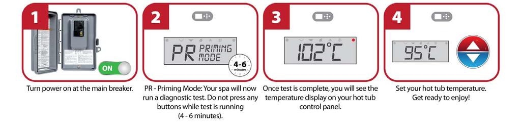
17 Fill it up! Preparation and Filling Fill the spa to its correct operating level. Be sure to open all valves and jets in the plumbing system before filling to allow as much air as possible to escape from the plumbing and the control system during the filling process. After turning the power on at the main power panel, the top-side panel display will go through specific sequences. These sequences are normal and display a variety of information regarding the configuration of the hot tub control. Priming Mode M019* This mode will last for 4-5 minutes or you can manually exit the priming mode after the pump(s) have primed. Regardless of whether the priming mode ends automatically or you manually exit the priming mode, the system will automatically return to normal heating and filtering at the end of the priming mode. During the priming mode, the heater is disabled to allow the priming process to be completed without the possibility of energizing the heater under low-flow or no-flow conditions. Nothing comes on automatically, but the pump(s) can be energized by pushing the Jet buttons. If the spa has a Circ Pump, it can be activated by pressing the Light button during Priming Mode. Priming the Pumps As soon as the above display appears on the panel, push the Jet button once to start Pump 1 in low-speed and then again to switch to high-speed. Also, push the Pump 2 or Aux button, if you have a 2nd pump, to turn it on. The pumps will now be running in high-speed to facilitate priming. If the pumps have not primed after 2 minutes, and water is not flowing from the jets in the spa, do not allow the pumps to continue to run. Turn off the pumps and repeat the process. Note: Turning the power off and back on again will initiate a new pump priming session. Sometimes momentarily turning the pump off and on will help it to prime. Do not do this more than 5 times. If the pump(s) will not prime, shut off the power to the spa and call for service. Important: A pump should not be allowed to run without priming for more than 2 minutes. Under NO circumstances should a pump be allowed to run without priming beyond the end of the 4-5 minute priming mode. Doing so may cause damage to the pump and cause the system to energize the heater and go into an overheat condition. Exiting Priming Mode You can manually exit Priming Mode by pressing a Temp button (Up or Down). Note that if you do not manually exit the priming mode as described above, the priming mode will be automatically terminated after 4-5 minutes. Be sure that the pump(s) have been primed by this time. Once the system has exited Priming Mode, the top-side panel will momentarily display the set temperature but the display will not show the temperature yet, as shown below. This is because the system requires approximately 1 minute of water or READY RANGE READY RANGE flowing through the heater to determine the water temperature and display it. *M019 is a Message Code. See Page 15. 3
18 Spa Behavior Pumps Press the Jets 1 button once to turn pump 1 on or off, and to shift between low- and high-speeds if equipped. If left running, the pump will turn off after a time-out period. The pump 1 low-speed will time out after 30 minutes. The high-speed will time out after 15 minutes. On non-circ systems, the low-speed of pump 1 runs when the blower or any other pump is on. If the spa is in Ready Mode (See page 6), Pump 1 low may also activate for at least 1 minute every 30 minutes to detect the spa temperature (polling) and then to heat to the set temperature if needed. When the low-speed turns on automatically, it cannot be deactivated from the panel, however the high speed may be started. Circulation Pump Modes If the system is equipped with a circ pump, it will be configured to work in one of three different ways: 1, The circ pump operates continuously (24 hours) with the exception of turning off for 30 minutes at a time when the water temperature reaches 3 F (1.5 C) above the set temperature (most likely to happen in very hot climates). 2, The circ pump stays on continuously, regardless of water temperature. 3, A programmable circ pump will come on when the system is checking temperature (polling), during filter cycles, during freeze conditions, or when another pump is on. The specific Circulation Mode that is used has been determined by the Manufacturer and cannot be changed in the field. Filtration and Ozone On non-circ systems, Pump 1 low and the ozone generator will run during filtration. On circ systems, the ozone will run with the circ pump. The system is factory-programmed with one filter cycle that will run in the evening (assuming the time-of-day is properly set) when energy rates are often lower. The filter time and duration are programmable. (See page 10) A second filter cycle can be enabled as needed. At the start of each filter cycle, the blower (if there is one) or Pump 2 (if there is one) will run briefly to purge its plumbing to maintain good water quality. Freeze Protection If the temperature sensors within the heater detect a low enough temperature, then the pump(s) and the blower automatically activate to provide freeze protection. The pump(s) and blower will run either continuously or periodically depending on conditions. In colder climates, an optional additional freeze sensor may be added to protect against freeze conditions that may not be sensed by the standard sensors. Auxiliary freeze sensor protection acts similarly except with the temperature thresholds determined by the switch. See your dealer for details. Clean-up Cycle (optional) When a pump or blower is turned on by a button press, a clean-up cycle begins 30 minutes after the pump or blower is turned off or times out. The pump and the ozone generator will run for 30 minutes or more, depending on the system. On some systems, you can change this setting. (See the Preferences section on page 12) 4
19 Temperature and Temp Range Adjusting the Set Temperature When using a panel with Up and Down buttons (Temperature buttons), pressing Up or Down will cause the temperature to flash. Pressing a temperature button again will adjust the set temperature in the direction indicated on the button. When the LCD stops flashing, the spa will heat to the new set temperature when required. If the panel has a single temperature button, pressing the button will cause the temperature to flash. Pressing the button again will cause the temperature to change in one direction (e.g. UP). After allowing the display to stop flashing, pressing the Temperature Button will cause the temperature to flash and the next press will change the temperature in the opposite direction (e.g. DOWN). Press-and-Hold If a Temperature button is pressed and held when the temperature is flashing, the temperature will continue to change until the button is released. If only one temperature button is available and the limit of the Temperature Range is reached when the button is being held, the progression will reverse direction. Dual Temperature Ranges This system incorporates two temperature range settings with independent set temperatures. The High Range designated in the display by an up arrow, and the Low Range designated in the display by a down arrow. These ranges can be used for various reasons, with a common use being a ready to use setting vs. a vacation setting. The Ranges are chosen using the menu structure below. Each range maintains its own set temperature as programmed by the user. This way, when a range is chosen, the spa will heat to the set temperature associated with that range. For example: High Range might be set between 80 F and 104 F. Key Low Range might be set between 50 F and 99 F. More specific Temp Ranges may be determined by the Manufacturer. Freeze Protection is active in either range. See Ready and Rest on Page 6 for additional heating control information. Indicates Flashing or Changing Segment Indicates Alternating or Progressive Message - every 1/2 second A temperature button, used for Action Light or dedicated Choose button, depending on control panel configuration Waiting time that keeps the last change to a menu item. Waiting time (depends on menu item) that reverts to original setting and ignores any change to that menu item. Set Temp will Show & Flash Press a Temp Button repeatedly to change the temperature. SET RANGE While temperature is flashing... High-Range vs. Low-Range Temp Choice SET RANGE SET RANGE OR Several Seconds Pressing and holding a Temp Button will also change the temperature. Toggle the Range arrows in the LCD. SET RANGE To next item in Main Menu SET RANGE Waiting Several Seconds Reverts to Original Setting Set Temp will Show & Flash Press a Temp Button repeatedly to change the temperature. SET RANGE FLTR1 SET RANGE FLTR1 SET RANGE FLTR1 OR Several Seconds Pressing and holding a Temp Button will also change the temperature. 5
20 Mode Ready and Rest In order for the spa to heat, a pump needs to circulate water through the heater. The pump that performs this function is known as the heater pump. The heater pump can be either a 2-Speed Pump 1 or a circulation pump. If the heater pump is a 2-Speed Pump 1, READY Mode will circulate water every 1/2 hour, using Pump 1 Low, in order to maintain a constant water temperature, heat as needed, and refresh the temperature display. This is known as polling. REST Mode will only allow heating during programmed filter cycles. Since polling does not occur, the temperature display may not show a current temperature until the heater pump has been running for a minute or two. Circulation Mode (See Page 4, under Pumps, for other circulation modes) If the spa is configured for 24HR circulation, the heater pump generally runs continuously. Since the heater pump is always running, the spa will maintain set temperature and heat as needed in Ready Mode, without polling. In Rest Mode, the spa will only heat to set temperature during programmed filter times, even though the water is being filtered constantly when in Circulation Mode. Key SET RANGE While the Temperature is still flashing, press Light repeatedly until MODE appears in the LCD. Indicates Flashing or Changing Segment Indicates Alternating or Progressive Message - every 1/2 second A temperature button, used for Action Light or dedicated Choose button, depending on control panel configuration SET READY SET REST Waiting Several Seconds Reverts to Original Setting REST RANGE FLTR1 Waiting time that keeps the last change to a menu item. Waiting time (depends on menu item) that reverts to original setting and ignores any change to that menu item. To next item in Main Menu If not toggled Toggle between READY and REST Pressing Light when the display is toggled will go to. READY Mode will allow the spa to Poll and determine a need for heat. The panel will maintain a current temperature display. REST Mode will not Poll and will only heat during filter cycles. The panel will not display a current temperature at all times. REST RANGE FLTR1 1 Hour REST RANGE REST RANGE REST RANGE REST RANGE REST RANGE The will display RUN PUMP FOR TEMP if the filtration pump has not run for over 1 hour. The will display normally during Filter Cycles or when the spa is in use. If the filtration pump has been off for an hour or more, when any function button, EXCEPT Light, is pressed on the panel, the pump used in conjuncton with the heater will run so that temperature can be sensed and displayed. Ready-in-Rest Mode READY/REST appears in the display if the spa is in Rest Mode and Jet 1 is pressed. It is assumed that the spa is being used and will heat to set temperature. While Pump 1 High can be turned on and off, Pump 1 Low will run until set temperature is reached, or 1 hour has passed. After 1 hour, the System will revert to Rest Mode. This mode can also be reset by entering the Mode Menu and changing the Mode. REST RANGE J READY/REST RANGE 6
NorthWind Hot Tubs by Coast Spas Manufacturing Inc Street, Langley BC Canada
 VERSION 01152016 NorthWind Hot Tubs by Coast Spas Manufacturing Inc. 6315 202 Street, Langley BC Canada 604 514 8111 info@coastspas.com www.coastspas.com 1 TABLE OF CONTENTS Basic Information Page 3 Hot
OWNER S MANUAL 2018 TABLE OF CONTENTS. Basic Information. Quick Start Guide. Important Safety Instructions Page 5
 1 TABLE OF CONTENTS Basic Information Quick Start Guide Page 3 Page 4 Important Safety Instructions Page 5 Preparation and Set-up for Your New Spa Page 6 Electrical Requirements Page 6 Draining & Winterizing
Coast Spas Manufacturing Inc Street, Langley BC Canada
 VERSION 01142016 Coast Spas Manufacturing Inc. 6315 202 Street, Langley BC Canada 604 514 8111 info@coastspas.com www.coastspas.com 1 TABLE OF CONTENTS General Information Quick Start Guide for Skim Filtration
NorthWind Hot Tubs by Coast Spas Manufacturing Inc Street, Langley BC Canada
 VERSION 01152016 NorthWind Hot Tubs by Coast Spas Manufacturing Inc. 6315 202 Street, Langley BC Canada 604 514 8111 info@coastspas.com www.coastspas.com 1 TABLE OF CONTENTS Basic Information Page 3 Hot
4230/6230/9230 SERIES OWNERS OPERATION GUIDE
 4230/6230/9230 SERIES OWNERS OPERATION GUIDE 104 CONTENTS Important Safety Instructions 2 INTRODUCTION Major Component Illustration 4 SYSTEM OPERATION Features & Function Visual Diagnostic System (VDS)
Coast Spas Manufacturing Inc Street, Langley BC Canada
 VERSION 01152016 Coast Spas Manufacturing Inc. 6315 202 Street, Langley BC Canada 604 514 8111 info@coastspas.com www.coastspas.com 1 TABLE OF CONTENTS General Information Coast Spas Quick Start Guide
Coast Spas Manufacturing Inc Street, Langley BC Canada
 VERSION 07312016 Coast Spas Manufacturing Inc. 6315 202 Street, Langley BC Canada 604 514 8111 info@coastspas.com www.coastspas.com 1 TABLE OF CONTENTS General Information Coast Spas Quick Start Guide
Coast Spas Manufacturing Inc Street, Langley BC Canada
 VERSION 07312015 Coast Spas Manufacturing Inc. 6315 202 Street, Langley BC Canada 604 514 8111 info@coastspas.com www.coastspas.com 1 TABLE OF CONTENTS General Information Coast Spas Quick Start Guide
OWNER S MANUAL 2019 TABLE OF CONTENTS. Table of Contents Page 2. Important GFCI Information Page 3. Basic Information Page 4. Quick Start Guide Page 5
 1 TABLE OF CONTENTS Table of Contents Page 2 Important GFCI Information Page 3 Basic Information Page 4 Quick Start Guide Page 5 Important Safety Instructions Page 6 Preparation and Set-up for Your New
TP600 and TP400 Control Panels
 TP600 and TP400 Control Panels Balboa Water Group Revolution Series User Interface and Programming Reference Simplified Menus System Model: BP1500 / BP1600 - Other BP-Series Systems as required. Software
Important safety instructions... Page 2. Preparation and set-up for your new spa... Page 3. Electrical requirements... Page 3
 1 CONTENTS: Important safety instructions... Page 2 Preparation and set-up for your new spa... Page 3 Electrical requirements... Page 3 Start-up instructions... Page 3 Fill instructions... Page 4 Draining
Spa Control System OWNER S MANUAL
 LIMITED WARRANTY ONE YEAR LIMITED WARRANTY: UNITED SPAS, INC. warrants, to the original purchaser, the Spa Equipment against defects in materials or workmanship for a period of one year from date of purchase.
OWNERS OPERATION GUIDE
 4220/6220/9220 SERIES OWNERS OPERATION GUIDE CONTENTS Important Safety Instructions 2 INTRODUCTION Major Component Illustration 4 SYSTEM OPERATION Features & Function Visual Diagnostic System (VDS) Spaside
4230/6230/9230 SERIES OWNERS OPERATION GUIDE
 4230/6230/9230 SERIES OWNERS OPERATION GUIDE CONTENTS Important Safety Instructions 2 INTRODUCTION Major Component Illustration 4 SYSTEM OPERATION Features & Function Visual Diagnostic System (VDS) Spaside
ULT L IMAT A E SERIES SOLID-STA T T A E SYSTEM OPERAT A ION MANUAL 8600
 ULTIMATE SERIES SOLID-STATE SYSTEM OPERATION MANUAL 8600 CONTENTS Important Safety Instructions 2 INTRODUCTION Major Component Illustration 4 SYSTEM OPERATION Heater Operation Spaside Control Spa Light
6500/7500 SERIES OWNERS OPERATION GUIDE
 6500/7500 SERIES OWNERS OPERATION GUIDE CONTENTS Important Safety Instructions Introduction 2 4 FEATURES & FUNCTION Ground Fault Circuit Interrupter (GFCI) Heater On Indicator Spaside Control Setting Filtration
4200/6200/9200 SERIES
 4200/6200/9200 SERIES OWNERS OPERATION GUIDE 85-0063-A Rev 9 04/09 CONTENTS Important Safety Instructions 2 INTRODUCTION Major Component Illustration 4 SYSTEM OPERATION Features & Function Visual Diagnostic
UNIVERSAL AIR SERIES SYSTEM OPERATION MANUAL
 UNIVERSAL AIR SERIES SYSTEM OPERATION MANUAL CONTENTS Important Safety Instructions 2 INTRODUCTION Major Component Illustration 4 SYSTEM OPERATION Illustration System Mis-Wire System Over Temperature System
OWNER S MANUAL 2018 TABLE OF CONTENTS. Table of Contents Page 2. General Information Page 3. Quick Start Guide for Skim Filtration Systems Page 4
 1 TABLE OF CONTENTS Table of Contents Page 2 General Information Page 3 Quick Start Guide for Skim Filtration Systems Page 4 Important Safety Instructions Page 5 Preparation and Set-up for Your New Spa
6000 AIR SERIES SYSTEM OPERATION MANUAL A-AZ Rev.0 5/07
 000 AIR SERIES SYSTEM OPERATI MANUAL -00A-AZ Rev.0 /0 CTENTS NOTES Important Safety Instructions INTRODUCTI Major Component Illustration SYSTEM OPERATI Illustration GFCI (Ground Fault Circuit Interrupter)
spatouch Menued Control Panels
 spatouch Menued Control Panels Balboa Water Group BP Series Systems User Interface and Programming Reference The spatouch menued panel is compatible with all BP systems that already support the TP800 and/or
ELECTRIC SPA-PAK HEATER INSTALLATION & OPERATING INSTRUCTIONS
 ELECTRIC SPA-PAK HEATER INSTALLATION & OPERATING INSTRUCTIONS CATALOG NO.: 6100.53O Effective: 03-15-05 Replaces: 02-01-05 INTRODUCTION The SPA-PAK Spa Heaters have been designed to provide efficient,
Spa Touch Control Panel with BP2100, BP6013 spa controllers. (Spa Owner s Manual insert)
") Spa Touch Control Panel with BP2100, BP6013 spa controllers. (Spa Owner s Manual insert) P.N. 7876C (export) February 12, 2015 For Spas equipped with BP2100, BP6013 controllers and Spa Touch panel. Spa
Spa Touch Control Panel with BP2100, BP6013 spa controllers. (Spa Owner s Manual insert) P.N. 7876C (export) February 12, 2015 For Spas equipped with BP2100, BP6013 controllers and Spa Touch panel. Spa
4200/6200/9200 SERIES OWNERS OPERATION GUIDE
 4200/6200/9200 SERIES OWNERS OPERATION GUIDE CONTENTS Important Safety Instructions 2 INTRODUCTION Major Component Illustration 4 SYSTEM OPERATION Features & Function Visual Diagnostic System (VDS) Spaside
TP800 and TP900 Series Control Panels
 TP800 and TP900 Series Control Panels Balboa Water Group User Interface and Programming Reference System Model: BP2500 / 2600 Software Version: 5.0 and later Panel Model: TP900 Series TP800 Series Software
TRANQUILITY ADVANCED HEATING SYSTEM
 TRANQUILITY ADVANCED HEATING SYSTEM MODELS: PBES-6010 PBES-6040 1000W Advanced Heating System 4000W Advanced Heating System Operation / Installation Instructions 85-0059-G Rev.03-6/13 INTRODUCTION The
4100/6100/7100 SERIES OWNERS OPERATION GUIDE
 4100/6100/7100 SERIES OWNERS OPERATION GUIDE CONTENTS Important Safety Instructions 2 INTRODUCTION Major Component Illustration 4 SYSTEM OPERATION Features & Function Visual Diagnostic System (VDS) Spaside
Spa Touch Control Panel with 2000, 2100 controllers. (Spa Owner s Manual insert)
") Spa Touch Control Panel with 2000, 2100 controllers (Spa Owner s Manual insert) P.N. 7876B February 11, 2015 For Spas equipped with BP2000, BP2100 controllers and Spa Touch panel. Spa Touch Control Panel
Spa Touch Control Panel with 2000, 2100 controllers (Spa Owner s Manual insert) P.N. 7876B February 11, 2015 For Spas equipped with BP2000, BP2100 controllers and Spa Touch panel. Spa Touch Control Panel
FREWIN STEAM SHOWER ENCLOSURE
 FREWIN STEAM SHOWER ENCLOSURE INSTALLATION AND USER MANUAL CONTENTS Steam Shower Enclosure Installation...2 Technical Information...2 Plumbing Requirements...2 Assembly...3 Tools and Materials...3 Installation...3
IMPORTANT SAFETY INSTRUCTIONS READ AND FOLLOW ALL INSTRUCTIONS SAVE THESE INSTRUCTIONS
 IMPORTANT LEAVE THESE INSTRUCTIONS WITH THIS UNIT Whirlpool / Chromatherapy / BubbleAir Operating Instructions IMPORTANT SAFETY INSTRUCTIONS READ AND FOLLOW ALL INSTRUCTIONS SAVE THESE INSTRUCTIONS INSTRUCTIONS
Bullfrog Spas Owners Manual
 Bullfrog Spas Owners Manual QUICK REFERENCE To assist you with the installation and maintenance service of your new spa, please fill out the following information and keep it on hand for future reference.
ARLEY STEAM SHOWER ENCLOSURE
 ARLEY STEAM SHOWER ENCLOSURE INSTALLATION AND USER MANUAL CONTENTS Steam Shower Enclosure Installation...2 Technical Information...2 Plumbing Requirements...2 Assembly...3 Tools and Materials...3 Installation...3
SPA HEATER INSTALLATION, OPERATION AND MAINTENANCE
 SPA INSTALLATION, OPERATION AND MAINTENANCE MODELS: ST SERIES 5.5 & 11kW 240V SINGLE PHASE BEFORE YOU BEGIN CHECK ALL ELECTRICAL CONNECTIONS TO ALL COMPONENTS WITHIN THE FOR TIGHTNESS. CONNECTIONS CAN
Owner s Manual. Model PH050006
 Owner s Manual Model PH050006 Manufactured By: Shanghai Qinxu Plastics Products Co., Ltd. No. 5151, Dongchuan Road Heqing Town, Pudong New Area Shanghai, CN 201201 IMPORTANT SAFETY INSTRUCTIONS The following
LEVENS STEAM SHOWER ENCLOSURE
 LEVENS STEAM SHOWER ENCLOSURE INSTALLATION AND USER MANUAL CONTENTS Steam Shower Enclosure Installation...2 Technical Information...2 Plumbing Requirements...2 Assembly...3 Tools and Materials...3 Installation...3
SAVE THESE INSTRUCTIONS
 SAVE THESE INSTRUCTIONS Important User Safety Instructions Your physiological response to hot water is subjective and depends on your age, health, and medical history. If you don t know your tolerance
INSTRUCTION MANUAL. Blue Whale Spa Ltd, 11 Glaisdale Drive East Nottingham, NG8 4GU
 INSTRUCTION MANUAL Balboa 500Z-Series Operation Guide Initial Start-up Your spa will enter Priming Mode ( ) when it is energized. During Priming Mode, press Jets button(s) repeatedly and be sure all pumps
Important Safety Instructions... Page 2. Cautions... Page 3. Start-Up Instructions... Page 4. Fill Instructions For Cascade Spa Owners Only...
 1 TABLE OF CONTENTS: Important Safety Instructions... Page 2 Cautions... Page 3 Setup and Delivery Guidelines Location of Your New Spa... Page 3 Electrical Requirements... Page 3 Start-Up Instructions...
Whirlpool Bathtub Model Number: MT618
 INSTALLATION AND OWNER'S MANUAL Whirlpool Bathtub Model Number: MT618 Please carefully read these instructions before you begin to install the products. 07/11 Rev A P/N:100056-03 Thank you for purchasing
INSTRUCTION MANUAL. Blue Whale Spa Ltd, 11 Glaisdale Drive East Nottingham, NG8 4GU
 INSTRUCTION MANUAL MVP260 Control Reference Card Non-Circ Operation Initial Start-up When your spa is first actuated, it will go into Priming mode, indicated by Please see the M-7 Installation Instruction
INSTRUCTION MANUAL. Blue Whale Spa Ltd, 11 Glaisdale Drive East Nottingham, NG8 4GU
 INSTRUCTION MANUAL Balboa 500DZ-Series Operation Guide Initial Start-up Your spa will enter Priming Mode ( ) when it is energized. During Priming Mode, press Jets button(s) repeatedly and be sure all pumps
AWP 3260 CWH Installation Instructions Hydro-massage Bathtub - UL 1795
 Tools you might need for proper installation galvanized nails or screws large level hammer or screw gun shims adhesive Thank you for purchasing Praxis Bathware. For best results, please read and follow
SYSTEM BASIC WHIRLPOOLS
 SYSTEM BASIC WHIRLPOOLS 114847-2-CB 2000 Kohler Co. IMPORTANT SAFETY INSTRUCTIONS ATTENTION INSTALLER: INSTRUCTIONS PERTAINING TO RISK OF FIRE, ELECTRIC SHOCK, OR INJURY TO PERSONS READ AND FOLLOW ALL
CERTIFICATE OF AUTHENTICITY
 CERTIFICATE OF AUTHENTICITY Thank you for your purchase. This certificate hereby verifies that the spa you have purchased from an Artesian Spas (May Manufacturing, LLC) authorized dealer is authentic,
PART B BRAND SPECIFIC MANUAL
 SPA OWNER S MANUAL IMPORTANT SAFETY INSTRUCTIONS PART B BRAND SPECIFIC MANUAL ELECTRICAL CONNECTION KEYPAD OPERATION SRS-M-B Read in conjunction with Part A General Manual to form a complete Owner s Manual
170-2 OWNER S MANUAL
 170-2 OWNER S MANUAL Table of Contents INFORMATION PAGES Important safety instructions 3-4 Warning Label Locations 5 Before you Begin 6 Choosing a Location 7-8 Setting Up 8 Operating the Smartub 170-2
geyser spas OWNERS MANUAL
 geyser spas OWNERS MANUAL Model: Serial Number: Date Installed: Dealer: Address: Telephone: Note: The serial number/identification label is located within the equipment compartment and skimmer housing.
CERTIFICATE OF AUTHENTICITY
 CERTIFICATE OF AUTHENTICITY Thank you for your purchase. This certificate hereby verifies that the spa you have purchased from an Artesian Spas (May Manufacturing, LLC) authorized dealer is authentic,
CONTENTS CONSIDERATIONS. General Plumbing Component Connection ILLUSTRATION. Control System CONFIGURATION. Voltage Verification CONNECTION
 AIR SERIES SYSTEM INSTALLATION MANUAL CONTENTS CONSIDERATIONS General Plumbing Component Connection 2 2 2 ILLUSTRATION Control System 3 CONFIGURATION Voltage Verification 4 CONNECTION Component Connection
OPERATION & INSTALLATION MANUAL
 OPERATION & INSTALLATION MANUAL BAPTISTRY HEATER AND CONTROL SYSTEM BES6000-HC & BES6000T-HC SERIES 5.5KW BES6005-HC & BES6005T-HC SERIES 11.0KW 510A N. SHERIDAN ST. CORONA, CA 92880 TABLE OF CONTENTS
Introduction. Spa Model: Power Pack Model: Serial #:
 Introduction Congratulations on your purchase of the finest whirlpool spa on the market today. Emerald Spa Corporation welcomes you to the Emerald Whirlpool Spa Life-style! We are confident that this purchase
Spas with 2 or 3 Pumps
 Topside Control Instructions for Spas with 2 or 3 Pumps 15bp501tp60102 1 Programming Menu Sequence 2 Powering on Your Spa After filling the spa through the filter assembly to the correct level remove the
Installation and Operation Manual MG-304. Please read this manual carefully before use.
 Installation and Operation Manual MG-304 Please read this manual carefully before use. 1 P a g e Important Safety Instructions: Warning! Use this unit only for its intended purposes or as described in
CERTIFICATE OF AUTHENTICITY
 CERTIFICATE OF AUTHENTICITY Thank you for your purchase. This certificate hereby verifies that the spa you have purchased from an Artesian Spas (May Manufacturing, LLC) authorized dealer is authentic,
Technical Support and Warranty Service
 Technical Support and Warranty Service For technical assistance or warranty service requests, please call a technical support representative at 877-547-8390. Factory trained technical support representatives
ALERT. Your new spa s GFCI will trip. A Ground Fault Interrupter (GFCI) Trip Test must occur to allow proper spa function.
 Trip Test must occur to allow proper spa function.") ALERT Your new spa s GFCI will trip. A Ground Fault Interrupter (GFCI) Trip Test must occur to allow proper spa function. Spas that come with MXBP20 and MXBP501 control systems come with special instructions
ALERT Your new spa s GFCI will trip. A Ground Fault Interrupter (GFCI) Trip Test must occur to allow proper spa function. Spas that come with MXBP20 and MXBP501 control systems come with special instructions
NEXT SOLID-STATE SYSTEM. P u m p. * A u x. e f
 e f s a i ECO-1 SERIES SOLID-STATE SYSTEM OPERATION MANUAL P u m p * Pum p 2 1 * A i r Light POWER CONTROL SWITCH Ref r to Oper tion Ma nual o r test ng and operational p r o c e d u r e c System V D S
Part #
 Notes: WWW.ARTESIANSPAS.COM Part # 11-1310-11 2013 Artesian Spas (May Manufacturing, LLC) Last Revised1/31/2013 Subject to change without notice. TABLE OF CONTENTS Congratulations... Important Safety Instructions...
This manual covers your new TidalFit
 This manual covers your new TidalFit Table of Contents Certificate of Authenticity... Important Safety Instructions... 1 TidalFit Specifications... 5 Electrical Requirements and Installation... 6 Electrical
Installation, Operation & Service Procedures
 Installation, Operation & Service Procedures Baptistry Heater System Model EQAS-CH HEATER ONLY PT#: 04-10029 REV.02 85-0139-C 08/12 TABLE O CONTENTS TABLE O CONTENTS/WARRANTY 1 IMPORTANT SAETY INSTRUCTIONS
HIGHLAND SERIES PORTABLE SPA
 OWNERS MANUAL HIGHLAND SERIES PORTABLE SPA OLYMPIA CASCADE TETON SIERRA QUALITY SPAS AND GAZEBOS SINCE 1976. TABLE OF CONTENTS IMPORTANT SERVICE INFORMATION...........1 IMPORTANT SAFETY INSTRUCTIONS...........2
O W N E R S M A N U A L
 cottage spas OW N E R S M A N UA L Model: Serial Number: Date Installed: Dealer: Address: Telephone: Note: The serial number/identification label is located within the equipment compartment and skimmer
Owner s Manual. English version R e v. 8, J a n u a r y
 Owner s Manual English version R e v. 8, J a n u a r y 2 0 0 9 MAINTENANCE TO PERFORM AT INDICATED INTERVALS Every 3 months Every 3 months Every 3 months Every 3 months Every month Annually As required
ALERT. Your new spa s GFCI will trip. A Ground Fault Interrupter (GFCI) Trip Test must occur to allow proper spa function.
 Trip Test must occur to allow proper spa function.") ALERT Your new spa s GFCI will trip. A Ground Fault Interrupter (GFCI) Trip Test must occur to allow proper spa function. Spas that come with MXBP20 and MXBP501 control systems come with special instructions
ALERT Your new spa s GFCI will trip. A Ground Fault Interrupter (GFCI) Trip Test must occur to allow proper spa function. Spas that come with MXBP20 and MXBP501 control systems come with special instructions
Water s Edge Spas. Owner s Guide Book
 Owner s Guide Book Dealer Support and Service For technical assistance or warranty service requests, contact your local dealer. Please take pictures of your area of concern and have them ready if the dealer
UNIVERSAL TEE STYLE Hydromassage Bath Heater INSTALLATION INSTRUCTIONS
 UNIVERSAL TEE STYLE Hydromassage Bath Heater INSTALLATION INSTRUCTIONS This Manual Covers: 7 Models SG100-15UP - 120V, 1500W SG202-20UP - 240V, 2000W CARTON CONTENTS: A - One (1) Whirlpool Bath Heater
Owner s Manual for. Spas with Multiple Pumps
 Owner s Manual for Spas with Multiple Pumps Service and Technical Support For technical assistance or warranty service requests, please call a technical support representative at 844-894-6659. Factory
Destination Collection Whirlpool Bath Installation Instructions
 Tools you might need for proper installation Galvanized Nails or Screws Large Level Hammer or Screw Gun Shims Adhesive Thank you for purchasing Praxis Bathware. For best results, please read and follow
champion spas OWNERS MANUAL
 champion spas OWNERS MANUAL Model: Serial Number: Date Installed: Dealer: Address: Telephone: Note: The serial number/identification label is located within the equipment compartment and skimmer housing.
Laurel Mountain Whirlpools. Walk-In Bathtub Installation Manual
 Laurel Mountain Whirlpools Walk-In Bathtub Installation Manual IMPORTANT SAFETY INSTRUCTIONS PLEASE READ AND FOLLOW ALL INSTRUCTIONS PROVIDED CAREFULLY Install to permit access for servicing An equipment
ECO SPA & POOL OWNERS MANUAL & INSTALLATION GUIDE
 ECO SPA & POOL OWNERS MANUAL & INSTALLATION GUIDE MODELS: ECO SPA 5.5-11 / ECO POOL 18-27 IMPORTANT SAFETY INSTRUCTIONS,INSTALLATIONIN STRUCTIONS,USER INSTRUCTIONS As when installing or using any high
Experience the Ultimate. Owners Guide. Built by May Manufacturing Inc. Victorville, California
 Experience the Ultimate GOLDClass Owners Guide Built by May Manufacturing Inc. Victorville, California TABLE OF CONTENTS CONGRATULATIONS 3 SAFETY WARNINGS 4 SPA CONFIGURATION and WATER CAPACITIES 7 ELECTRICAL
READ AND FOLLOW ALL INSTRUCTIONS SAVE THESE INSTRUCTIONS
 READ AND FOLLOW ALL INSTRUCTIONS SAVE THESE INSTRUCTIONS 1 IMPORTANT SAFETY INSTRUCTIONS Read the instructions The appliance is not to be used by persons (including children) with reduced physical, sensory
HU2. Spa Owner s Manual. PN Rev L Domestic
 HU2 Spa Owner s Manual 1 PN 378100-2 Rev L Domestic OWNER S INFORMATION DEALER Company Address Phone E-mail INSTALLER Company Address Phone SPA Model (see below) Serial Number (see below) Color Date of
C.A.I. Customer Service Department 1462 East Ninth Street Pomona, CA Toll Free: CAL-SPAS Fax:
 LTR20051000, Rev E CONTACT INFORMATION For customer service, please contact your authorized dealer immediately. If you need additional information and/or assistance, please contact: C.A.I. Customer Service
Owner s Manual for. Single Pump Spas
 Owner s Manual for Single Pump Spas Service and Technical Support For technical assistance or warranty service requests, please call a technical support representative at 844-894-6659. Factory trained
LED Series Hot Tub Owner s Manual J-210, J-220, J-230 Models TB VAC, 3-Wire Connection USE COPPER CONDUCTORS ONLY. WIRE SIZE MUST BLU BRN JP1
 Transformer 230 VAC Control WHT BRN BRN Circ. Pump J21 J12 J14 J16 J20 K1 K2 K3 K4 J4 4 2 JP1 8 7 6 5 3 1 J1 J2 J3 BLU J11 J15 F1 K5 K7 K8 BRN J13 J5 Heater IN Heater OUT F1 BRN 20A 250V SC-20 J6 LO Main
Burlington TM Denali TM Tacoma TM
 Burlington TM Denali TM Tacoma TM 6530-680, Rev. C Attention New Spa Owner! Congratulations on the purchase of your new Sundance 680 series spa! The following is a list of automated functions and maintenance
Lifestyle Series. Designed with assistance from medical professionals to. Improve Well Being with Relaxation Therapy
 Lifestyle Series Designed with assistance from medical professionals to Improve Well Being with Relaxation Therapy Service and Technical Support For technical assistance or warranty service requests, please
Control Series Operation Instructions Page 1. "Digi VII"
 Control Series Operation Instructions Page 1 Do not take a sauna if using alcohol, drugs or medications. "Digi VII" Control Models Digi VII 60 min or Digi VII 24 hr (Model # 1601-15, and 1601-15-1) Read
Lifestyle Series. Designed with assistance from medical professionals to. Improve your Well Being with Relaxation, Massage & Hydro Therapies
 Lifestyle Series Designed with assistance from medical professionals to Improve your Well Being with Relaxation, Massage & Hydro Therapies Service and Technical Support For technical assistance or warranty
Factory Direct Walk-In Tubs WALK-IN TUB. Installation Manual. For Model Numbers VT2848, VT2853, VT3153 and VT3255
 Factory Direct Walk-In Tubs WALK-IN TUB Installation Manual For Model Numbers VT2848, VT2853, VT3153 and VT3255 FACTORY DIRECT WALK-IN TUBS Thank you for choosing an Vitality Tubs Walk-In Tub. Vitality
RELAX. REVITALIZE. RESTORE. LUXURY SPA UNIT Installation Manual. English. For Model Numbers 2848, 2853, 3153 and 3255
 RELAX. REVITALIZE. RESTORE. LUXURY SPA UNIT Installation Manual For Model Numbers 2848, 2853, 3153 and 3255 English RELAX. REVITALIZE. RESTORE. Thank you for choosing a Secure Spa Luxury Spa Unit. Secure
INSTALLATION & INSTRUCTION MANUAL
 INSTALLATION & INSTRUCTION MANUAL CONTENTS TUFF SPA INSTALLATION REQUIREMENTS........3 IMPORTANT SAFETY INSTRUCTIONS... 4 WARNINGS... 5 IMPORTANT CAUTION... 6 WIRING DIAGRAM... 7 110v to 220v CONVERSION...
bahia cayman lagunas palermo
 bahia cayman lagunas palermo Table of Contents 1.0 Important Spa Owner Information...1 2.0 FCC Notice...1 3.0 Important Safety Instructions...2 3.1 Important CSA Safety Instructions (Canada Only)...3
S-Series 3 Person Infrared Sauna Touch Pad and Bluetooth IG-870-SH/S870 User Manual
 S-Series 3 Person Infrared Sauna Touch Pad and Bluetooth IG-870-SH/S870 User Manual This Product is covered by: US Patents No. 8,692,168 Canadian Patents No. 2,729,500 2,794,059 & 2,813,340 and other Patents
BULLFROG SPAS OWNERS MANUAL
 BULLFROG SPAS OWNERS MANUAL QUICK REFERENCE To assist you with the installation and maintenance service of your new spa, please fill out the following information and keep it on hand for future reference.
LED Series Hot Tub Owner s Manual J-210, J-220, J-230 Models TB VAC, 3-Wire Connection USE COPPER CONDUCTORS ONLY. WIRE SIZE MUST BLU BRN JP1
 Transformer 230 VAC Control WHT BRN BRN Circ. Pump J21 J12 J14 J16 J20 K1 K2 K3 K4 J4 4 2 JP1 8 7 6 5 3 1 J1 J2 J3 BLU J11 J15 F1 K5 K7 K8 BRN J13 J5 Heater IN Heater OUT F1 BRN 20A 250V SC-20 J6 LO Main
S-Series 3 Person Infrared Sauna Touch Pad and Bluetooth IG-830-SH/S830 User Manual
 S-Series 3 Person Infrared Sauna Touch Pad and Bluetooth IG-830-SH/S830 User Manual This Product is covered by: US Patents No. 8,692,168 Canadian Patents No. 2,729,500 2,794,059 & 2,813,340 and other Patents
Whirlpool Tub USER S MANUAL
 Whirlpool Tub USER S MANUAL Model: PH050006/PH050011, 110V~, 60Hz, 1500W BLUE WAVE PRODUCTS 1745 WALLACE AVE. ST. CHARLES, IL 60174 Read this manual before operation IMPORTANT SAFETY INSTRUCTIONS WARNING1:
Aquatic Fitness System 2003 Owner s Manual
 ii Table of Contents IMPORTANT SAFETY INSTRUCTIONS...1 READ AND FOLLOW ALL INSTRUCTIONS CAREFULLY... 1 HYPERTHERMIA... 4 DO S AND DON T S...5 Do s...5 Don ts...5 DANGER SIGN...6 AQUATIC FITNESS SYSTEM
Diamond Whirlpool/Air pool INSTALLATION & OPERATION INSTRUCTION
 Diamond Whirlpool/Air pool INSTALLATION & OPERATION INSTRUCTION WARNING When using this unit, precautionary steps should be followed to prevent electrical shock or personal injury. 1. Do not permit children
Personal Hydro-Massage System: 10-Jet Tower Model. Owner s Manual AB Kohler Co.
 10-Jet Tower Model Personal Hydro-Massage System: Owner s Manual 114176-5-AB 2002 Kohler Co. IMPORTANT SAFETY INSTRUCTIONS. READ AND FOLLOW ALL INSTRUCTIONS. INSTRUCTIONS PERTAINING TO RISK OF FIRE, ELECTRIC
Owner s Guide. for. Single Pump Spas 1
 Owner s Guide for Single Pump Spas 1 Customer Support and Warranty Service We are delighted to welcome you to the Signature Spas family of owners. Every Signature Spa is handcrafted in the United States
INSTALLATION AND OPERATING INSTRUCTIONS Page 1
 INSTALLATION AND OPERATING INSTRUCTIONS Page 1 Do not take a sauna if using alcohol, drugs or medications. Pregnant women or persons with poor health should consult their physician before using any sauna.
DRAFT INSTALLATION INSTRUCTIONS. Solid-State Series !! NOTE!! Covers the following models: Refer to INSERT for additional information
 INSTALLATION INSTRUCTIONS Solid-State Series!! NOTE!! Covers the following models: " CS6100 - CS7100 " CS6200 - CS9200 " CS6220 - CS9220 " CS6230 - CS9230 " CS6500 - CS7500 " CS6330 - CS9300 " CS9400 -
ENJOY Your QCA Spa VS501 PAK (VL260 TOPSIDE) OWNER S MANUAL
 OWNER S MANUAL") ENJOY Your QCA Spa VS501 PAK (VL260 TOPSIDE) OWNER S MANUAL This owner s manual is for YOU! It will show you how to operate and maintain your very own spa. We think it is important for you to take a few
ENJOY Your QCA Spa VS501 PAK (VL260 TOPSIDE) OWNER S MANUAL This owner s manual is for YOU! It will show you how to operate and maintain your very own spa. We think it is important for you to take a few
IMPORTANT INSTALLATION and OPERATING INSTRUCTIONS
 IMPORTANT INSTALLATION and OPERATING INSTRUCTIONS To be provided to the Walk-In Tub owner/user. INSTRUCTIONS PERTAINING TO A RISK OF FIRE, ELECTRIC SHOCK OR INJURY TO PERSONS IMPORTANT SAFETY INSTRUCTIONS
USER MANUAL
 USER MANUAL 1 Contents Content Page Number Warning 3-4 Caution Notice 5 Installation Notice 6 Assembly 7-9 Operation 10 Maintenance of water in the water tank body 13 Maintaining water 14 Cleaning the
EL/GL Series - Mach 3 ML550 User Guide
 EL/GL Series - Mach 3 ML550 User Guide Heat Cool Warm Jets 1 Jets 2 Blower Light Mode Note regarding EL and GL systems: Mach 3 EL and GL systems function identically, but conform to different International